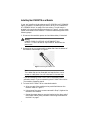
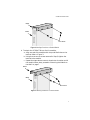
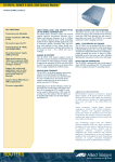
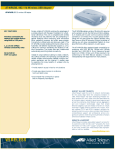
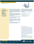
1
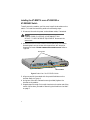
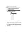
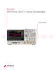
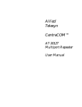
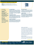
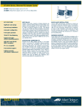
AT-BRKT18 Wall-mounting Brackets Installation Guide PN 613-10355 Rev C Copyright 2000 Allied Telesyn International, Corp. 960 Stewart Drive Suite B, Sunnyvale CA 94086 USA All rights reserved. No part of this publication may be reproduced without prior written permission from Allied Telesyn International, Corp. Ethernet is a registered trademark of Xerox Corporation. All other product names, company names, logos or other designations mentioned herein are trademarks or registered trademarks of their respective owners. Allied Telesyn International Corp. reserves the right to make changes in specifications and other information contained in this document without prior written notice. The information provided herein is subject to change without notice. In no event shall Allied Telesyn be liable for any incidental, special, indirect, or consequential damages whatsoever, including but not limited to lost profits, arising out of or related to this manual or the information contained herein, even if Allied Telesyn International Corp. has been advised of, known, or should have known, the possibility of such damages. Table of Contents Preface .............................................................................................................. v Document Conventions ...................................................................................... v Contacting Allied Telesyn ................................................................................. vi For Technical Support and Services.......................................................... vi Technical Support E-mail Addresses ........................................................ vi FTP Server................................................................................................. vii For Sales or Corporate Information ................................................................ vii Tell Us What You Think .................................................................................. vii Installation ....................................................................................................... 1 Overview ............................................................................................................. 1 Required Tools .................................................................................................... 1 Verifying the Package Contents ........................................................................ 2 Reviewing Safety Precautions ........................................................................... 2 Installing the AT-BRKT18 on a Module ........................................................... 4 Installing the AT-BRKT18 on an AT-GS903SX or AT-GS904SX Switch........ 6 Mounting the Module on the Wall ..................................................................... 7 AT-BRKT18 Installation Guide Feedback .............................................. 11 Technical Support Fax Order ................................................................... 13 Incident Summary ............................................................................................ 13 iii Preface Document Conventions Throughout this guide, you will notice several conventions that you should become familiar with first before installing the product. Note A note provides additional information. Caution A caution indicates that performing or omitting a specific action may result in equipment damage or loss of data. Warning A warning indicates that performing or omitting a specific action may result in bodily injury. v Contacting Allied Telesyn For Technical Support and Services Americas United States, Canada, Mexico, Central America, South America Tel: 1 (800) 428-4835 Fax: 1 (503) 639-3176 Germany Germany, Switzerland, Austria, Eastern Europe Tel: (+49) 30-435-900-126 Fax: (+49) 30-435-70-650 Asia Singapore, Taiwan, Thailand, Malaysia, Indonesia, Korea, Philippines, China, India, Hong Kong Tel: (+65) 3815-61 Fax: (+65) 3833-83 Italy Italy, Spain, Portugal, Greece, Turkey, Israel Tel: (+39) 02-416047 Fax: (+39) 02-419282 Australia Australia, New Zealand Tel: 1 (800) 000-880 Fax: (+61) 2-9438-4966 Japan Tel: (+81) 3-3443-5640 Fax: (+81) 3-3443-2443 France France, Belgium, Luxembourg, The Netherlands, Middle East, Africa Tel: (+33) 1-60-92-15-25 Fax: (+33) 1-69-28-37-49 United Kingdom United Kingdom, Denmark, Norway, Sweden, Finland, Iceland Tel: (+44) 1-235-442560 Fax: (+44) 1-235-442680 Technical Support E-mail Addresses United States and Canada [email protected] Latin America, Mexico, Puerto Rico, Caribbean, and Virgin Islands [email protected] United Kingdom, Sweden, Norway, Denmark, and Finland [email protected] vi AT-BRKT18 Installation Guide FTP Server Address: gateway.centre.com [lowercase letters] Login: anonymous [lowercase letters] Password: your e-mail address [requested by the server at login] For Sales or Corporate Information Allied Telesyn International, Corp. 19800 North Creek Parkway, Suite 200 Bothell, WA 98011 Tel: 1 (425) 487-8880 Fax: 1 (425) 489-9191 Allied Telesyn International, Corp. 960 Stewart Drive, Suite B Sunnyvale, CA 94086 Tel: 1 (800) 424-4284 (USA and Canada) Fax: 1 (408) 736-0100 Tell Us What You Think In our continuing efforts to help you get the most from Allied Telesyn, we look for new and better ways to document our products. If you have comments or suggestions to improve this or other documents, please fill out the “AT-BRKT18 Installation Guide Feedback” on page 11 and return the form to us at the address or fax number provided. vii Installation Overview The AT-BRKT18 kit contains two brackets that are designed for vertically mounting the following Allied Telesyn products on a wall: ❑ AT-GS903SX and AT-GS904SX Switches ❑ AT-810SL Fanout ❑ AT-3012T Hub ❑ AT-3004SL and AT-3008SL Repeaters ❑ AT-3600 Series Repeaters Required Tool In addition to the package contains you will need the following tools for proper installation. ❑ Hammer ❑ Drill and 3/16-inch bit (or equivalent) ❑ Phillips screwdriver ❑ Pencil ❑ Awl (or other type of punch) 1 Verifying the Package Contents Check your AT-BRKT18 package for the following items: ❑ Two brackets ❑ Four panhead Phillips screws ❑ Four Bantam plugs ❑ Four flathead screws (for AT-GS903SX or AT-GS904SX installation only) Reviewing Safety Precautions Please review the following safety precautions to wall-mount modules and switches before you begin to install the brackets. Warning LIGHTNING DANGER DANGER: DO NOT WORK on equipment or CABLES during periods of LIGHTNING ACTIVITY. Warning POWER CORD IS USED AS A DISCONNECTION DEVICE. TO DE-ENERGISE EQUIPMENT disconnect the power cord. Warning ELECTRICAL - TYPE CLASS 1 EQUIPMENT THIS EQUIPMENT MUST BE EARTHED. Power plug must be connected to a properly wired earth ground socket outlet. An improperly wired socket outlet could place hazardous voltages on accessible metal parts. Caution PLUGGABLE EQUIPMENT, the socket outlet shall be installed near the equipment and shall be easily accessible. 2 AT-BRKT18 Installation Guide Warning ELECTRICAL - CORD NOTICE Use power cord, maximum 4.5 meters long, rated 10 amp minimum, 250V, made of <HAR> cordage molded IEC 320 connector on one end and on the other end a plug approved by the country of end use. Caution MOUNTING INSTRUCTIONS CAUTION: The bracket enables wall-mounting of products for operation in the VERTICAL position. HORIZONTAL MOUNTING must ONLY BE DONE when the product is equipped with key-hole slots on the bottom of the chassis. Caution DO NOT detach rubber feet from the product unless an Allied Telesyn vertical mounting bracket is being used. Warning Only use to install products in the VERTICAL position. DO NOT USE to install product HORIZONTALLY. Caution Air vents must not be blocked and must have free access to the room ambient air for cooling. 3 Installing the AT-BRKT18 on a Module If your are installing the brackets on an AT-GS903SX or AT-GS904SX switch, proceed to “Installing the AT-BRKT18 on an AT-GS903SX or AT-GS904SX Switch” on page 6 for instructions. To wall-mount a product in the vertical orientation as shown in Figure 5, you first must install the brackets to the module. To install the brackets, perform the following steps: 1. Disconnect the module’s power cord and data cables, if attached. Warning POWER CORD IS USED AS A DISCONNECTION DEVICE. TO DE-ENERGISE EQUIPMENT disconnect the power cord. 2. Remove the corner screws and the rubber feet from the bottom of the module. See example in Figure 1. Figure 1 Removing the Rubber Feet Note The rubber feet can be discarded, but keep the four corner screws in a safe place. You will use them in the next step. If you are attaching the AT-BRKT18 to a standard module, proceed to step 3. If you are attaching the AT-BRKT18 to a slimline module, proceed to step 4. 3. To install the AT-BRKT18 on a standard module: a. Align one end of the module to the pre-drilled holes on the bracket. Refer to Figure 2. b. Using two of the corner screws removed in Step 2, tighten the bracket to the module. c. Repeat the steps above to mount a bracket to the other end of the module. When done, proceed to “Mounting the Module on the Wall” on page 7. 4 AT-BRKT18 Installation Guide Bracket Module Corner Screws Figure 2 Attaching a Bracket on a Standard Module 4. To attach the AT-BRKT18 to a slim-line module: a. Align one end of the module with the pre-drilled holes on the bracket. Refer to Figure 3. b. Using the two corner screws removed in Step 2, tighten the bracket to the module. c. Repeat the steps above to mount a bracket on the other end of the module. When done, proceed to “Mounting the Module on the Wall” on page 7. Bracket Module Corner Screws Figure 3 Attaching a Bracket on a Slim-line Module 5 Installing the AT-BRKT18 on an AT-GS903SX or AT-GS904SX Switch To wall-mount the module, you first must install the brackets on the switch. To install the brackets, perform the following steps: 1. Disconnect the switch’s power cord and data cables, if attached. Warning POWER CORD IS USED AS A DISCONNECTION DEVICE. TO DE-ENERGISE EQUIPMENT disconnect the power cord. 2. Remove one of the corner screws from the bottom of the module. Removing both corner screws at the same time, will cause the faceplate to loosen. Do not remove the center screw. Refer to Figure 4. Corner Screws DO NOT REMOVE Figure 4 Bottom View of the AT-GS903SX Module 3. Align one end of the module with the pre-drilled holes on the bracket. Refer to Figure 2. 4. Using two of the four flathead screws (provided) tighten the bracket to the module. 5. Repeat steps 2 through 5 to install a bracket on the other end of the switch. When done, proceed to “Mounting the Module on the Wall” on page 7. 6 AT-BRKT18 Installation Guide Mounting the Module on the Wall After you have installed the brackets on the module mount the module on the wall by performing the following steps: Note The module must be mounted vertically with the power receptacle towards the top to achieve maximum convection cooling. See Figure 5. Power Cord Brackets Module Figure 5 Completed Bracket Installation (Standard Module) 7 1. Choose a location to wall-mount the module. Caution Do not drop the module. Damage to the module will occur if it is dropped. Because the module may be heavy and awkward to hold against the wall, you may want to get assistance with the next step. 2. Place the back of the module flat against the wall; pass a pencil through the front holes on the bracket and mark the four screw locations on the wall. Refer to Figure 6. Figure 6 Marking the Screw Locations on a Wall (Side View) 3. Place the module on a secure surface while you use an awl (or equivalent) to punch the four pilot holes into the wall as marked in step 2. 4. Drill the four holes with a 3/16-inch drill bit. 5. If you are mounting the module on wallboard, insert the supplied Bantam plugs into the holes. If necessary, gently tap the plugs with a hammer. 8 AT-BRKT18 Installation Guide 6. Place the module on the wall, aligning it with the drilled holes. Secure the brackets to the wall using the supplied panhead Phillips screws. See Figure 7. Figure 7 Attaching the Module to the Wall The wall-mounted module is now ready for use. Refer to the installation guide provided with the module for instuctions on how to connect the power and data cables. 9 Appendix A AT-BRKT18 Installation Guide Feedback Please tell us what additional information you would like to see discussed in this guide. If there are topics you would like information on that were not covered in this guide, please photocopy this page, answer the questions and fax or mail this form back to Allied Telesyn. The mailing address and fax number are at the bottom of the page. Your comments are valuable when we plan future revisions of this guide. I found the following the most valuable ___________________________ _______________________________________________________________ _______________________________________________________________ _______________________________________________________________ _______________________________________________________________ I would like the following more developed ________________________ _______________________________________________________________ _______________________________________________________________ _______________________________________________________________ _______________________________________________________________ I would find this guide more useful if _____________________________ _______________________________________________________________ _______________________________________________________________ _______________________________________________________________ Please fax or mail your feedback. Fax to 1-408-736-0100. Or mail to: Allied Telesyn International, Corp. c/o Technical Communications 960 Stewart Drive, Suite B Sunnyvale, CA 94086 USA PN 613-10355 Rev C 11 Appendix B Technical Support Fax Order Name _________________________________________________________________ Company ______________________________________________________________ Address _______________________________________________________________ City______________________ State/Province_______________________________ Zip/Postal Code ________________ Country_______________________________ Phone______________________________ Fax________________________________ Incident Summary Model number of Allied Telesyn product I am using _______________________ Firmware release number of Allied Telesyn product________________________ Other network software products I am using (e.g., network managers) ______________________________________________________________________ ______________________________________________________________________ Brief summary of problem ______________________________________________ ______________________________________________________________________ Conditions (List the steps that led up to the problem.______________________ ______________________________________________________________________ ______________________________________________________________________ ______________________________________________________________________ ______________________________________________________________________ ______________________________________________________________________ ______________________________________________________________________ ______________________________________________________________________ ______________________________________________________________________ Detailed description (Please use separate sheet) Please also fax printouts of relevant files such as batch files and configuration files. When completed, fax this sheet to the appropriate Allied Telesyn office. Fax numbers can be found on page vi. 13