1
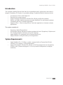
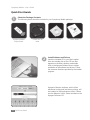
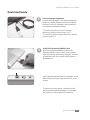
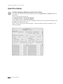
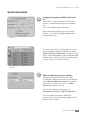
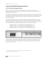
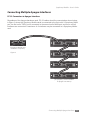
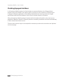
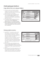
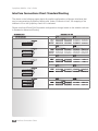
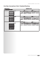
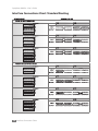
User’s Guide
v1.0 - June 2007
Table of Contents
Introduction
System Requirements
Quick Start Guide
Check the Package Contents Install Software and Drivers
Quick Start Guide
Connect Apogee Interfaces
Install the Symphony Mobile Card
Configure Symphony Mobile for playback from iTunes Quick Start Guide
Configuring Symphony Mobile with Logic Pro
VBus and High Performance Settings
Connecting Multiple Apogee Interfaces
PC-32 Connection to Apogee Interfaces
Connecting Multiple Apogee Interfaces
PC-32 Connection to Apogee Interfaces
Clocking Apogee Interfaces
Using a Master Clock (such as Apogee’s Big Ben)
Clocking to the first interface
Interface Connections Chart: Standard Routing
Interface Connections Chart: Advanced Option Routing
Installing the X-Symphony card
Troubleshooting
Owner’s Record
Registration and Warranty Information
Service Information
Warnings
Copyright Notice
Declarations of Conformity
1
1
2
2
2
3
3
3
4
5
5
5
6
6
7
7
8-9
9
9
10-13
14-15
16-17
18
19
20
20
21
21
22
Symphony Mobile – User’s Guide
Introduction
The Symphony Mobile ExpressCard offers the unparalleled quality, performance and value of
Apogee’s Symphony PCI system in a portable package. Symphony Mobile’s features include:
•
•
•
•
•
•
32 channels of 24-bit 192k Digital I/O
Extremely low system latency
Supports Apogee Rosetta 800, Rosetta 200, AD16X and DA16X hardware
Simple, one cable interface between any Apple MacBook Pro and Apogee hardware
Compatible with any CoreAudio application.
Apogee’s VBus – virtual routing within a CoreAudio application or between multiple
applications.
The system consists of:
•
•
•
•
•
Symphony Mobile ExpressCard
A compatible Apogee hardware interface equipped with an X-Symphony X-Option card
PC-32 cables between interfaces and to the computer
Apple MacBook Pro equipped with an ExpressCard/34 slot
Apogee Maestro routing/low latency mixer application
System Requirements
•
•
Apple MacBook Pro 1.83 GHz or greater, equipped with an ExpressCard/34 slot;
minimum 1G of memory, 2 GB recommended.
Apogee Rosetta 800, Rosetta 200, AD16X or DA16X equipped with an X-Symphony
X-Option card. (Please see pages 10-15 for all possible configurations of Apogee
interfaces).
Introduction
1
Symphony Mobile – User’s Guide
Quick Start Guide
1
Check the Package Contents
The following items should be included in your Symphony Mobile package:
Symphony Mobile
ExpressCard
3 meter, PC-32
cable
Installation disc
2
Users’ Guide
Install Software and Drivers
Insert the included CD in your Mac’s optical
drive slot, double click on the CD icon that
appears on the Mac’s desktop, and double
click on the Apogee Software icon to initiate
installation of the software and drivers. Follow
the onscreen directions provided by the installer
program.
Apogee’s Maestro software, which offers
advanced routing and low latency mixing, will
be installed in the Applications folder. Please
see the Maestro User’s Guide included on the
Apogee Software CD.
2
Quick Start Guide
Symphony Mobile – User’s Guide
Quick Start Guide
3
Connect Apogee Interfaces
Connect the included PC-32 cable between the
Symphony Mobile ExpressCard and the MAIN
connector on the X-Symphony card installed in
your Apogee hardware interface.
To install X-Symphony cards in Apogee
interfaces, please consult pages 16-17.
To connect multiple Apogee Interfaces, please
consult pages 6-7.
4
Install the Symphony Mobile Card
Slide the Symphony Mobile card into the
ExpressCard slot on your Mac, press inward
until the latching mechanism engages, and then
release the card; the card will pop outward a
slight amount.
Verify that the ExpressCard icon appears in the
Menu Bar at the upper right hard corner of the
screen.
To remove the card, press it inward until the
latching mechanism disengages, and release
the card; the card will pop out completely.
Quick Start Guide
3
Symphony Mobile – User’s Guide
Quick Start Guide
5
4
Configure Symphony Mobile for playback from iTunes
Open the OS X utility Audio Midi Setup (found in the Applications > Utilities folder on
your Mac):
Click on the Audio Devices tab.
Set Default Output to Symphony Mobile
Set Properties For to Symphony Mobile
Verify that the sample rate of the first hardware interface is the same as indicated in the
Format field under Audio Input.
Open iTunes and play an audio selection – audio should be present at outputs 1-2 of
the first interface.
Quick Start Guide
Symphony Mobile – User’s Guide
Quick Start Guide
6
Configuring Symphony Mobile with Logic
Pro
Open Audio > Audio Hardware and Drivers >
Drivers > CoreAudio and check the Enabled
box.
Click “OK” when prompted by Logic.
Select Symphony Mobile in the Driver field
(Figure 1), and click Try (Re)–Launch when
prompted by Logic.
Figure 1
To “customize” the I/O routing labels in Logic to
match Symphony Mobile hardware I/O, open
Audio > Audio Configuration. Under the View
menu, select I/O Labels. Under the Drivers’ I/O
Label column, option–click the first radio button
of each group of I/O labels (Figure 2).
Figure 2
7
VBus and High Performance Settings
Configuring Symphony Mobile with Logic
To instantiate VBus signal paths, open Maestro,
select Window>Maestro Control, and select
the desired numbers of buses in the VBus
Selections drop down menu.
For the best latency performance, set
Performance Tuning to High Performance.
For more details concerning VBus and
Performance Tuning, please see page 4 of the
Maestro User’s Guide
Quick Start Guide
5
Symphony Mobile – User’s Guide
Connecting Multiple Apogee Interfaces
PC-32 Connection to Apogee Interfaces
A wide array of system input/output configurations may be achieved according to the
Apogee interfaces used, the order in which interfaces are connected, and the internal routing
configuration of each interface.
For example, it’s possible to connect two AD16Xs and 2 DA16Xs (all set to Standard routing) to
provide 32 analog inputs and 32 analog outputs. When the AD/DAs are set to Advanced routing,
it’s possible to connect 1 AD16X and 1 DA16X, providing 16 channels of analog I/O and 16
channels of digital I/O.1
The Interface Connection Chart on pages 10-15 depicts all possible interfaces configurations,
as well as the mapping of interface I/O to the 32 channels of Symphony Mobile I/O for each
possible configuration. For example, the chart entry for the connection of 1 AD16X and 1 DA16X
(set to Advanced routing) indicates the following (when the AD is connected first):
•
•
•
•
Symphony inputs 1-16 correspond to the AD’s analog inputs 1-16;
Symphony outputs 1-16 correspond to the AD’s digital outputs 1-16;
Symphony inputs 17-32 correspond to the DA’s digital inputs 1-16;
Symphony outputs 17-32 correspond to the DA’s analog outputs 1-16
AD-16X & DA-16X
1-16
From Computer
M
T
M
T
INPUT
17-32
AD-16X: Analog In
DA-16X: Digital In
AD-16X: Digital Out
DA-16X: Analog Out
OUTPUT
Keep in mind that the Symphony Mobile driver makes 32 channels of I/O available at all times
to CoreAudio compatible software regardless of the number of Apogee hardware channels
connected. Thus, 32 channels of Symphony I/O are presented in the software I/O selection,
even if they’re not all used.
1. Please see page 8 of the AD-16X user’s guide for more information about
standard and advanced option routing.
6
Connecting Multiple Apogee Interfaces
Symphony Mobile – User’s Guide
Connecting Multiple Apogee Interfaces
PC-32 Connection to Apogee Interfaces
Regardless of the Apogee hardware used, PC-32 cables should be connected as shown below
in figure 3, where the Symphony Mobile cards is connected to the first unit’s X-Symphony MAIN
port, the first unit’s THRU port is connected to the second unit’s MAIN port, and so on until all
interfaces are connected. A maximum of 4 interfaces may be connected to a Symphony Mobile
card.
(Symphony Mobile card
installed in computer)
Figure 3
(X-Symphony Cards installed
in Apogee converters)
Connecting Multiple Apogee Interfaces
7
Symphony Mobile – User’s Guide
Clocking Apogee Interfaces
In a Symphony Mobile system, the first interface (connected directly to the ExpressCard)
serves as the clock master to the entire system, and may be set to Internal or External clock
in Apogee’s Maestro application. All remaining interfaces must receive a word clock signal
synchronous with the first interface’s clock source, whether Internal or External.
When a Symphony Mobile system is booted, the first interface will switch to the clock source
specified in Maestro (Internal or External) while the remaining interfaces will switch automatically
to their external word clock source.
The two most common ways to accomplish the necessary word clock connections are depicted
on the next page.
8
Clocking Apogee Interfaces
Symphony Mobile – User’s Guide
Clocking Apogee Interfaces
Using a Master Clock (such as Apogee’s Big Ben)
1 Connect a word clock cable between
outputs of the master clock and each
interface’s word clock input, and terminate
the input with a 75 ohm load.
2 Boot your Mac, open the Maestro app,
and set Clock Source Select for the
first interface to External. All remaining
interfaces should switch to their external
word clock source.
3 If interfaces aren’t displayed in Maestro,
select Tools > Reset Symphony
Clocking and click on External Clock.
4 When opening CoreAudio applications,
ensure that the master clock is running
at the same sample rate as the session
you’re opening.
Big Ben
Interface 1
Interface 2
Interface 3
Interface 4
Figure A. Optimum clocking configuration using BIG BEN
Clocking to the first interface
1 Install BNC “T connectors on the word
clock inputs of the second, third and
fourth interfaces (if present). Connect a
word clock cable from the first interface’s
word clock output to the BNC “T”
connector on the next interface, from that
interface to the next, until all the word
clock inputs have been chained together,
as shown in figure B. Terminate the word
clock input of the last interface with a 75
ohm load.
2 Boot your Mac, open the Maestro app,
and set Clock Source Select for the first
interface to Internal. All remaining interfaces
should switch to their external word clock
source.
3 When opening CoreAudio applications, the
first interface should switch to the same
sample rate as the session you’re opening,
and all remaining interfaces should follow.
Interface 1
Interface 2
Interface 3
Interface 4
Figure B. Correct clocking configuration to the master device’s
clock output using BNC “T“ connectors
Clocking Apogee Interfaces
9
Symphony Mobile – User’s Guide
Interface Connections Chart: Standard Routing
The charts on the following pages depict all possible configurations of Apogee interfaces that
may be connected per Symphony Mobile card. Under “Channels in Use”, the mapping of the
interface’s I/O to the Symphony card’s I/O is indicated.
Please note that AD and DA16X possible configurations change based on the whether units are
in Standard or Advanced Routing.
AD-16X & DA-16X
1-16
17-32
1-16
17-32
1-16
17-32
1-16
17-32
1-16
17-32
M
T
M
T
M
T
M
T
M
T
M
T
M
T
M
T
10 Interface Connections Chart
Symphony Mobile – User’s Guide
Interface Connections Chart: Standard Routing
AD-16X & DA-16X continued
1-16
17-32
1-16
17-32
1-16
17-32
M
T
M
T
M
T
M
T
M
T
M
T
M
T
M
T
M
T
M
T
Interface Connections Chart 11
Symphony Mobile – User’s Guide
Interface Connections Chart: Standard Routing
AD-16X, DA-16X & ROSETTA 800
1-16
17-32
1-16
17-32
1-16
17-32
1-16
17-32
1-16
17-32
1-16
17-32
1-16
17-32
M
T
M
T
M
T
M
T
M
T
M
T
M
T
M
T
M
T
M
T
ROSETTA 800 and AD-16X & DA-16X
M
T
M
T
M
T
M
T
M
T
M
T
M
T
M
T
M
T
M
T
12 Interface Connections Chart
Symphony Mobile – User’s Guide
Interface Connections Chart: Standard Routing
ROSETTA 800 and AD-16X & DA-16X continued
1-16
17-32
1-16
17-32
1-16
17-32
M
T
M
T
M
T
M
T
M
T
M
T
M
T
ROSETTA 800
From Computer
M
T
INPUT
OUTPUT
1-16
From Computer
M
T
M
T
M
T
17-32
INPUT
OUTPUT
ROSETTA 800 #1
ROSETTA 800 #2
1-16
From Computer
M
T
ROSETTA 800 #1
17-32
INPUT
OUTPUT
ROSETTA 800 #1
ROSETTA 800 #2
ROSETTA 800 #3
M
T
1-16
From Computer
M
T
M
T
17-32
INPUT
OUTPUT
ROSETTA 800 #1
ROSETTA 800 #2
ROSETTA 800 #3
ROSETTA 800 #4
M
T
M
T
Interface Connections Chart 13
Symphony Mobile – User’s Guide
Interface Connections Chart: Advanced Option Routing
INTERFACE SET
CHANNELS IN USE
AD-16X & DA-16X
1-16
From Computer
M
T
17-32
AD-16X: Analog In
INPUT
AD-16X: Digital Out
OUTPUT
1-16
From Computer
M
T
17-32
DA-16X: Digital In
INPUT
DA-16X: Analog Out
OUTPUT
1-16
From Computer
M
T
M
T
INPUT
M
T
M
T
AD-16X: Digital Out
1-16
INPUT
17-32
DA-16X: Digital In
DA-16X: Digital In
DA-16X: Analog Out
DA-16X: Analog Out
OUTPUT
1-16
From Computer
M
T
AD-16X: Analog In
AD-16X: Digital Out
OUTPUT
From Computer
M
T
17-32
AD-16X: Analog In
INPUT
17-32
AD-16X: Analog In
DA-16X: Digital In
AD-16X: Digital Out
DA-16X: Analog Out
OUTPUT
AD-16X, DA-16X & ROSETTA 800
1-16
From Computer
M
T
M
T
INPUT
M
T
14 Interface Connections Chart
AD-16X: Digital Out
OUTPUT
1-16
From Computer
M
T
17-32
AD-16X: Analog In
ROSETTA 800 #1
17-32
DA-16X: Digital In
INPUT
OUTPUT
DA-16X: Analog Out
ROSETTA 800 #1
Symphony Mobile – User’s Guide
Interface Connections Chart: Advanced Option Routing
INTERFACE SET
CHANNELS IN USE
AD-16X & DA-16X
1-16
From Computer
M
T
17-32
AD-16X: Analog In
INPUT
AD-16X: Digital Out
OUTPUT
1-16
From Computer
M
T
17-32
DA-16X: Digital In
INPUT
DA-16X: Analog Out
OUTPUT
1-16
From Computer
M
T
M
T
INPUT
M
T
M
T
AD-16X: Digital Out
1-16
INPUT
17-32
DA-16X: Digital In
DA-16X: Digital In
DA-16X: Analog Out
DA-16X: Analog Out
OUTPUT
1-16
From Computer
M
T
AD-16X: Analog In
AD-16X: Digital Out
OUTPUT
From Computer
M
T
17-32
AD-16X: Analog In
INPUT
17-32
AD-16X: Analog In
DA-16X: Digital In
AD-16X: Digital Out
DA-16X: Analog Out
OUTPUT
AD-16X, DA-16X & ROSETTA 800
1-16
From Computer
M
T
M
T
INPUT
M
T
AD-16X: Digital Out
OUTPUT
1-16
From Computer
M
T
17-32
AD-16X: Analog In
ROSETTA 800 #1
17-32
DA-16X: Digital In
INPUT
DA-16X: Analog Out
ROSETTA 800 #1
OUTPUT
Interface Connections Chart 15
Symphony Mobile – User’s Guide
Installing the X-Symphony card
Your X-Symphony card should include the following:
•
•
•
•
1 X-Symphony circuit board
1 X-Symphony Coverplate
2 aluminium standoffs
1 plastic standoff
1
Remove the top cover of the host interface.
2
Remove the Option Card coverplate, and set
aside the screws for later use.
3
Remove the two interface circuit board screws
indicated at left, and set them aside for later use
4
Install the two aluminium standoffs in the
threaded holes vacated by the screws.
5
On the X-Symphony card, install the plastic
standoff in the hole adjacent to the multi-pin
motherboard connector.
2
4
3
Plastic standoff here
5
16 Installing the X-Symphony card
Symphony Mobile – User’s Guide
Installing the X-Symphony card
6
Install the X-Symphony Coverplate, and
secure it to the host interface using two
screws from Step 2.
7
Insert the Port connector end of the X-Symphony card through the appropriate cutouts
in the coverplate, and carefully place the multi-pin motherboard connector in the mating
connector found on the host interface motherboard.
8
After verifying the alignment of the multi-pin and the mating connectors, firmly press
down on the X-Symphony card, over the connector, until the pins are completely seated
in the mating connector.
9
Re-install the circuit board screws from Step 3 in
the locations indicated below.
6
9
10
Replace the top cover of the host interface.
Installing the X-Symphony card 17
Symphony Mobile – User’s Guide
Troubleshooting
Q: Two messages “An error has occurred…” and “Symphony is now configured correctly” are
alternately displayed onscreen. How can I stop this and get the system to settle down?
A: There are a few reasons this may occur:
There may be a mismatch exists between the CoreAudio sample rate (as indicated in
the OS X utility Audio Midi Setup) and the hardware’s sample rate. This occurs most
frequently when the first hardware interface is clocked externally to a Master clock
such as Apogee’s Big Ben. Be sure that the Master clock is set to the same sample
rate as the CoreAudio sample rate.
All Hardware interfaces aren’t synchronized – verify that all hardware interfaces are
receiving clock from the master clock.
Q: My Apogee interfaces aren’t appearing in Maestro – how can I remedy this?
A: Interfaces won’t appear in Maestro until they are properly connected and clocked;
make sure that the Lock indications on each hardware interface indicate a stable lock
at the correct sample rate.
If some interfaces are appearing but others aren’t, be sure that the configuration of
interfaces connected is supported, i.e listed in the Interface Connections Chart on
10-15.
Keep in mind that setting an AD or DA16X in Advanced routing will change the number
of interfaces that may be connected. Thus, 2 ADs and 2 DAs in Standard routing will
all appear in Maestro, while only the first AD/DA pair appears when set in Advanced
routing.
Q: When Apogee hardware interfaces don’t appear in Maestro, how can I set the first interface
to External clock?
A: When first configuring a Symphony setup with an external Master clock, one may
encounter the situation whereby the first interface must be set to External Clock in
Maestro, but can’t appear in Maestro until clock is correctly configured. To overcome
this conundrum, select the Maestro menu item Tools > Reset Symphony Clocking; a
dialog box appears offering the options to set clock on the first hardware interface to
External or Internal.
18 Troubleshooting
Symphony Mobile – User’s Guide
Owner’s Record
The serial number is located on the rear panel of the unit. We suggest you record the serial number in the
space provided below. Refer to it whenever you call an authorized Apogee Electronics repair facility or the
manufacturer. Please be sure to return your completed warranty card immediately!
Symphony Mobile card Serial No.____________________________________________________________
Purchase Date___________________________________________________________________________
Dealer__________________________________________________________________________________
Phone__________________________________________________________________________________
Address_________________________________________________________________________________
CAUTION:
Any changes or modifications not expressly approved by APOGEE ELECTRONICS CORPORATION
could void your authority to operate this equipment under the FCC rules.
Please register this unit by filling in the included registration card, or registering online at:
http://www.apogeedigital.com/register/
Owner's Record 19
Symphony Mobile – User’s Guide
Registration and Warranty Information
Be sure to register your Symphony Mobile card, either by filling in the enclosed Registration Card or by
completing the on-line registration form at our Web site: http://www.apogeedigital.com/support/. If you do so,
Apogee can contact you with any update information. As enhancements and upgrades are developed, you
will be contacted at the registration address. Firmware updates are free for the first year of ownership unless
otherwise stated. Please address any inquiries to your dealer or directly to Apogee at:
APOGEE ELECTRONICS CORPORATION,
1715 Berkeley St, Santa Monica, CA 90404, USA.
Tel: (310) 584-9394
Fax: (310) 584-9385
Email: [email protected]
Web: http://www.apogeedigital.com
APOGEE ELECTRONICS CORPORATION warrants this product to be free of defects in material and
manufacture under normal use for a period of 12 months. The term of this warranty begins on the date of sale
to the purchaser. Units returned for warranty repair to Apogee or an authorized Apogee warranty repair facility
will be repaired or replaced at the manufacturer’s option, free of charge.
ALL UNITS RETURNED TO APOGEE OR AN AUTHORIZED APOGEE REPAIR FACILITY MUST BE
PREPAID, INSURED AND PROPERLY PACKAGED, PREFERABLY IN THEIR ORIGINAL BOX. Apogee
reserves the right to change or improve design at any time without prior notification. Design changes are
not implemented retroactively, and the incorporation of design changes into future units does not imply the
availability of an upgrade to existing units.
This warranty is void if Apogee determines, in its sole business judgment, the defect to be the result of abuse,
neglect, alteration or attempted repair by unauthorized personnel.
The warranties set forth above are in lieu of all other warranties, expressed or implied, and Apogee specifically
disclaims any and all implied warranty of merchantability or of fitness for a particular purpose. The buyer
acknowledges and agrees that in no event shall the company be held liable for any special, indirect, incidental
or consequential damages, or for injury, loss or damage sustained by any person or property, that may result
from this product failing to operate correctly at any time.
USA: Some states do not allow for the exclusion or limitation of implied warranties or liability for incidental or
consequential damage, so the above exclusion may not apply to you. This warranty gives you specific legal
rights, and you may have other rights which vary from state to state.
Service Information
The Symphony Mobile card contains no user-serviceable components: refer to qualified service personnel for
repair or upgrade. Your warranty will be voided if you tamper with the internal components. If you have any
questions with regard to the above, please contact Apogee.
In the event your Symphony Mobile card needs to be upgraded or repaired, it is necessary to contact Apogee
prior to shipping, and a Return Materials Authorization (RMA) number will be assigned. This number will serve
as a reference for you and helps facilitate and expedite the return process. Apogee requires that shipments be
pre-paid and insured — unless otherwise authorized in advance.
IMPORTANT: ANY SHIPMENT THAT IS NOT PRE-PAID OR IS SENT WITHOUT AN RMA NUMBER WILL
NOT BE ACCEPTED.
20 Registration and Warranty Information
Symphony Mobile – User’s Guide
Warnings
FCC warning
This equipment has been tested and found to comply with the limits for a Class A digital device, pursuant
to Part 15 of the FCC rules. These limits are designed to provide reasonable protection against harmful
interference when operated in a commercial environment. This equipment generates, uses, and can radiate
radio frequency energy and, if not installed and used in accordance with the instruction manual, may cause
harmful interference to radio communications. Operation of this equipment in a residential area is likely to
cause harmful interference, in which case the user will be required to take whatever measures necessary to
correct the interference at his own expense.
Copyright Notice
The Apogee Symphony Mobile card is a computer-based device, and as such contains and uses software
in ROMs. This software, and all related documentation, including this User’s Guide contain proprietary
information which is protected by copyright laws. All rights are reserved. No part of the software and its related
documentation may be copied, transferred, or modified. You may not modify, adapt, translate, lease, distribute,
resell for profit or create derivative works based on the software and its related documentation or any part
thereof without prior written consent from Apogee Electronics Corporation, U.S.A.
Warnings and Copyright 21
Symphony Mobile – User’s Guide
Declarations of Conformity
This device complies with Part 15 of the FCC Rules. Operation is subject to the following two conditions:
1. This device may not cause harmful interference
2. This device must accept any interference received, including interference that may cause undesired
operation.
This equipment has been tested and found to comply with the limits of a Class A digital device, pursuant
to Part 15 of the FCC Rules. These limits are designed to provide reasonable protection against harmful
interference in a residential installation. This equipment generates, uses and can radiate radio frequency
energy and, if not installed and used in accordance with the instructions, may cause harmful interference
to radio communications. If this equipment does cause harmful interference to radio or television reception,
which can be determined by turning the equipment off and on, the user is encouraged to try to correct the
interference by one or more of the following measures:
1. Re-orient or relocate the receiving antenna.
2. Increase the separation between the equipment and receiver.
3. Connect the equipment into an outlet on a different circuit from that to which the receiver is connected.
4. Consult the dealer or an experienced radio/TV technician for help.
NOTE: The use of non-shielded cable with this equipment is prohibited.
CAUTION: Changes or modifications not expressly approved by the manufacturer responsible for compliance
could void the user’s authority to operate the equipment.
Apogee Electronics Corporation, Betty Bennett, CEO.
Industry Canada Notice
This Class A digital apparatus meets all requirements of the Canadian Interference-Causing Equipment
Regulations. Cet appareil numérique de la classe A respecte toutes les exigences du Règlement sur le
matérial brouilleur du Canada.
Declaration of Conformity – CE
Apogee Electronics Corporation hereby declares that the product, the Symphony Mobile card, to which this
declaration relates, is in material conformity with the following standards or other normative documents:
EN55022:1998, EN55024:1998
EN61000-3-2, EN61000-3-3, EN61000-4-2, EN61000-4-3, EN61000-4-4, EN61000-4-5, EN61000-4-6,
EN61000-4-8, EN61000-4-11
Declaration of Conformity – Japan
Apogee Electronics Corporation hereby declares that the Symphony Mobile card, to which this declaration
relates, is in material conformity with the VCCI Class A standard.
Declaration of Conformity – Australia
Apogee Electronics Corporation hereby declares that the Symphony Mobile card is in material conformity with
AN/NZS standard requirements.
22 Declarations of Conformity
Symphony Mobile
User’s Guide
v1.0 - June 2007
www.apogeedigital.com