1
Eiconcard™ Connections for Linux
User’s Guide
www.dialogic.com
Copyright © 2000-2009 Dialogic Corporation. All Rights Reserved. You may not reproduce this document in whole or in part without permission in
writing from Dialogic Corporation at the address provided below.
All contents of this document are furnished for informational use only and are subject to change without notice and do not represent a commitment
on the part of Dialogic Corporation or its subsidiaries ("Dialogic"). Reasonable effort is made to ensure the accuracy of the information contained
in the document. However, Dialogic does not warrant the accuracy of this information and cannot accept responsibility for errors, inaccuracies or
omissions that may be contained in this document.
INFORMATION IN THIS DOCUMENT IS PROVIDED IN CONNECTION WITH DIALOGIC® PRODUCTS. NO LICENSE, EXPRESS OR IMPLIED, BY
ESTOPPEL OR OTHERWISE, TO ANY INTELLECTUAL PROPERTY RIGHTS IS GRANTED BY THIS DOCUMENT. EXCEPT AS PROVIDED IN A SIGNED
AGREEMENT BETWEEN YOU AND DIALOGIC, DIALOGIC ASSUMES NO LIABILITY WHATSOEVER, AND DIALOGIC DISCLAIMS ANY EXPRESS OR
IMPLIED WARRANTY, RELATING TO SALE AND/OR USE OF DIALOGIC PRODUCTS INCLUDING LIABILITY OR WARRANTIES RELATING TO FITNESS
FOR A PARTICULAR PURPOSE, MERCHANTABILITY, OR INFRINGEMENT OF ANY INTELLECTUAL PROPERTY RIGHT OF A THIRD PARTY.
Dialogic products are not intended for use in medical, life saving, life sustaining, critical control or safety systems, or in nuclear facility applications.
Due to differing national regulations and approval requirements, certain Dialogic products may be suitable for use only in specific countries, and
thus may not function properly in other countries. You are responsible for ensuring that your use of such products occurs only in the countries
where such use is suitable. For information on specific products, contact Dialogic Corporation at the address indicated below or on the web at
www.dialogic.com.
It is possible that the use or implementation of any one of the concepts, applications, or ideas described in this document, in marketing collateral
produced by or on web pages maintained by Dialogic may infringe one or more patents or other intellectual property rights owned by third parties.
Dialogic does not provide any intellectual property licenses with the sale of Dialogic products other than a license to use such product in accordance
with intellectual property owned or validly licensed by Dialogic and no such licenses are provided except pursuant to a signed agreement with
Dialogic. More detailed information about such intellectual property is available from Dialogic's legal department at 9800 Cavendish Blvd., 5th Floor,
Montreal, Quebec, Canada H4M 2V9. Dialogic encourages all users of its products to procure all necessary intellectual property licenses required
to implement any concepts or applications and does not condone or encourage any intellectual property infringement and disclaims any responsibility
related thereto. These intellectual property licenses may differ from country to country and it is the responsibility of those who develop the concepts
or applications to be aware of and comply with different national license requirements.
Dialogic, Dialogic Pro, Brooktrout, Diva, Cantata, SnowShore, Eicon, Eicon Networks, NMS Communications, NMS (stylized), Eiconcard, SIPcontrol,
Diva ISDN, TruFax, Exnet, EXS, SwitchKit, N20, Making Innovation Thrive, Connecting to Growth, Video is the New Voice, Fusion, Vision,
PacketMedia, NaturalAccess, NaturalCallControl, NaturalConference, NaturalFax and Shiva, among others as well as related logos, are either
registered trademarks or trademarks of Dialogic Corporation or its subsidiaries. Dialogic's trademarks may be used publicly only with permission
from Dialogic. Such permission may only be granted by Dialogic's legal department at 9800 Cavendish Blvd., 5th Floor, Montreal, Quebec, Canada
H4M 2V9. Any authorized use of Dialogic's trademarks will be subject to full respect of the trademark guidelines published by Dialogic from time
to time and any use of Dialogic's trademarks requires proper acknowledgement.
Windows is a registered trademark of Microsoft Corporation in the United States and/or other countries. Other names of actual companies and
products mentioned herein are the trademarks of their respective owners.
Dialogic Corporation License Agreement for use of Software
This is an Agreement between you, the Company, and your Affiliates (referred to in some instances as "You" and in other instances as "Company") and all Your Authorized
Users and Dialogic Corporation ("Dialogic").
YOU SHOULD CAREFULLY READ THIS SOFTWARE LICENSE AGREEMENT ("AGREEMENT"), WHETHER IT IS BEING MADE AVAILABLE TO YOU AS PART OF SEALED PACKAGING
AND/OR VIA DOWNLOADING, BEFORE OPENING THE APPLICABLE PACKAGING AND/OR COMMENCING THE APPLICABLE DOWNLOADING. BY OPENING THE APPLICABLE
PACKAGING AND/OR COMMENCING THE APPLICABLE DOWNLOADING, YOU AGREE TO AND ACCEPT THE TERMS AND CONDITIONS OF THIS AGREEMENT. IF YOU DO NOT
AGREE WITH OR ARE UNWILLING TO ACCEPT THESE TERMS AND CONDITIONS, YOU MAY RETURN THE APPLICABLE PACKAGING IN UNOPENED "AS NEW" CONDITION
(INCLUDING ALL DOCUMENTATION AND BINDERS OR OTHER CONTAINERS) FOR A FULL REFUND AND/OR YOU SHOULD NOT COMMENCE THE APPLICABLE DOWNLOADING.
BY DOWNLOADING, INSTALLING, COPYING OR OTHERWISE USING THE ENCLOSED SOFTWARE ("PROGRAM"), WHETHER SUCH PROGRAM WAS MADE AVAILABLE TO YOU
AS PART OF SEALED PACKAGING AND/OR VIA DOWNLOADING, YOU FURTHER AGREE AND ACKNOWLEDGE THAT YOU HAVE READ THIS AGREEMENT AND UNDERSTAND
IT, AND THAT BY TAKING ANY ONE OR MORE OF SUCH STEPS/ACTIONS YOU AGREE TO BE BOUND BY SUCH TERMS AND CONDITIONS. DIALOGIC IS UNWILLING TO
LICENSE THE PROGRAM TO YOU IF YOU DO NOT ACCEPT AND AGREE TO BE BOUND BY THE TERMS AND CONDITIONS OF THIS AGREEMENT.
Intellectual Property
The enclosed Program and all accompanying documentation are individually and collectively owned by Dialogic Corporation ("Dialogic"), its subsidiaries and/or its suppliers
and are protected by all applicable intellectual property laws and international treaty provisions. Therefore, You and Your Authorized Users must treat the Program and
documentation like any other material so protected, except as expressly permitted in this Agreement. In particular, but without limitation, You acknowledge that the
Program and its accompanying documentation constitute valuable intellectual property rights, including without limitation trade secrets and copyrights, and confidential
information of Dialogic. The Program and all programs developed thereunder and all copies thereof (including without limitation translations, compilations, partial copies
with modifications and updated works) are proprietary to Dialogic and title to all applicable copyrights, trade secrets, patents and other intellectual property rights therein
remains in Dialogic, its subsidiaries, and/or its suppliers. Except as expressly permitted in this Agreement, You shall not sell, transfer, publish, disclose, display or otherwise
make available the Program or copies thereof to others. You agree to secure and protect the Program, its accompanying documentation and copies thereof in a manner
consistent with the maintenance of Dialogic's rights therein and to take appropriate action by instruction or agreement with Your employees and/or consultants who are
permitted access to the Program to satisfy Your obligations hereunder. Violation of any provision of this paragraph shall be the basis for immediate termination of this
Agreement. Because unauthorized use or transfer of the Program or documentation may diminish substantially the value of such materials and irrevocably harm Dialogic,
if You breach the provisions of this Section of this Agreement, Dialogic shall be entitled to injunctive and/or other equitable relief, in addition to other remedies afforded
by law, to prevent a breach of this Section of this Agreement.
Grant of License
Subject to the terms and conditions of this Agreement Dialogic grants to You a non-exclusive, personal, non-transferable license to use the Program in object code form
only and solely in accordance with the following terms and conditions:
You may make, install and use only one (1) copy of the Program on a single-user computer, file server, or on a workstation of a local area network, and only in conjunction
with a legally acquired Dialogic® hardware or software product You may also make one copy solely for backup or archive purposes;
The primary Authorized User on the computer on which the Program is installed may make a second copy for his/her exclusive use on either a home or portable computer;
• You may copy the Program into any machine readable or printed form for backup or modification purposes in support of Your use of one copy of the Program;
• You may distribute the Program in object code only and only as part of, or integrated by You into, a computer system that (i) contains a Dialogic hardware product, (ii)
includes a substantial amount of other software and/or hardware manufactured or marketed by You and (iii) is marketed and sublicensed to an end user for the end
user's own internal use in the regular course of business (a "Licensed System");
• Each end user to whom a Licensed System is distributed must agree to license terms with respect to the Program that are at least as protective of Dialogic's rights in the
Program as those set forth in this Agreement;
• You shall receive one (1) Program master disk, and shall be solely responsible for copying the Program into the Licensed Systems and for warranting the physical media
on which it is copied
• You may make one (1) copy of the documentation accompanying the Program, provided that all copyright notices contained within the documentation are retained;
• You may modify the Program and/or merge it into another Program for Your use in one computer; (any portion of this Program will continue to be subject to the terms
and conditions of this Agreement);
page 2
• You may transfer the Program, documentation and the license to another eligible party within Your Company if the other party agrees to accept the terms and conditions
of this Agreement. If You transfer the Program and documentation, You must at the same time either transfer all copies whether in printed or machine readable form to
the same party or destroy any copies not transferred; this includes all modifications and portions of the Program contained in or merged into other Programs;
• You shall not remove, and each copy of the Program shall contain, the same copyright, proprietary, patent and/or other applicable intellectual property or other ownership
notices, plus any restricted rights legends that appear in the Program and/or this Agreement and, if You copy the Program onto media to which a label may be attached,
You shall attach a label to the media that includes all such notices and legends that appear on the Program master disk and envelope;
• You may not rent or lease the Program. You may not reverse engineer, decompile or disassemble the Program. Except as is strictly necessary for You to integrate the
Program with other software and/or hardware to produce the Licensed Systems, You shall not copy, modify or reproduce the Program or documentation in any way. You
shall use Your best efforts to ensure that any user of the Program does not reverse engineer, decompile or disassemble the Program to derive a source code equivalent
of the Program;
• If You transfer possession of any copy, modification or merged portion of the Program or documentation to another party in any way other than as expressly permitted
in this Agreement, this license is immediately and automatically terminated;
• The Program may be used only in conjunction with Dialogic hardware;
• The Program shall not be exported or re-exported in violation of any export provisions of the United States or any other applicable jurisdiction.
Upgrades
If the Program is provided as an upgrade and the upgrade is an upgrade from another product licensed to You and Your Authorized Users by Dialogic, the upgrade is
governed by the license agreement earlier provided with that software product package and the present Agreement does not grant You additional license(s).
Term
The Agreement is effective until terminated. You may terminate it at any time by notifying Dialogic and/or by destroying the Program and all accompanying documentation
together with all copies, modifications and merged portions in any form. The Agreement will also terminate automatically upon the occurrence or lack of occurrence of
certain terms and/or conditions set forth in this Agreement, or if You fail to comply with any term or condition of this Agreement. You agree that upon any such termination
You shall destroy or return to Dialogic the Program and all accompanying documentation supplied by Dialogic, together with any and all copies, modifications and merged
portions in any form. All provisions of this Agreement relating to disclaimers of warranties, limitation of liability, remedies, or damages, and licensor's proprietary rights
shall survive termination.
Limited Warranty
Dialogic solely warrants the media on which the Program is furnished to You to be free from defects in materials and workmanship under normal use for a period of ninety
(90) days from the date of purchase by You as evidenced by a copy of Your receipt. If such a defect appears within the warranty period, You may return the defective media
to Dialogic for replacement without charge provided Dialogic, in good faith, determines that it was defective in materials or workmanship. Replacement is Your sole remedy
with respect to such a defect. Dialogic offers no warranty for Your reproduction of the Program. This Limited Warranty is void if failure of the Program has resulted from
accident, misuse, abuse or misapplication.
Disclaimers, Limitations of Liability and Customer Remedies
Except as set forth in the "Limited Warranty" Section of this Agreement, the Program and accompanying documentation are provided to You "as is." Neither Dialogic, its
subsidiaries, its suppliers, nor its licensor(s) (if any) warrants that the Program will meet Your requirements or that its use will be uninterrupted or error-free. Except as
set forth in the "Limited Warranty" Section, EACH OF DIALOGIC, ITS SUBSIDIARIES, ITS SUPPLIERS AND ITS LICENSOR(S) (IF ANY) DISCLAIMS ANY AND ALL
REPRESENTATIONS AND WARRANTIES, EXPRESS OR IMPLIED, WITH RESPECT TO THE PROGRAM AND ACCOMPANYING DOCUMENTATION, INCLUDING BUT NOT LIMITED
TO THE IMPLIED WARRANTIES OF NON-INFRINGEMENT, MERCHANTABILITY, FITNESS FOR A PARTICULAR PURPOSE, OR AGAINST LATENT DEFECTS. Except as set forth in
the "Limited Warranty" Section, neither Dialogic, its subsidiaries, its suppliers, nor its licensor(s) (if any) shall have any liability to You or any third party for any claim, loss
or damage of any kind, including but not limited to lost business profits, business interruption, loss of information, or other pecuniary loss and indirect, punitive, incidental,
economic, consequential or special damages, arising out of or in connection with this Agreement and/or the use, inability to use the Program and/or the Program's
performance or inability to perform nor from or in connection with the Program's accompanying documentation, or any data or equipment related thereto or used in
connection therewith. In no event shall Dialogic's, its subsidiaries', its suppliers' or its licensor(s)'s liability for damages, whether arising out of contract, negligence, warranty,
or patent or copyright infringement, exceed the fees You paid for the Program. No representation or warranty regarding the Program may be made without Dialogic's, its
subsidiaries', its suppliers', or its licensor(s)'s (if any) prior written consent, and any warranty or representation made by You or Your customers regarding the Program
shall not constitute an obligation of Dialogic, its subsidiaries, its suppliers, or other licensor(s) (if any). This limited warranty gives You specific legal rights. You may have
other rights, which may vary from jurisdiction to jurisdiction. Also, as some jurisdictions do not allow the exclusion or limitation for certain damages, some of the above
limitations may not apply to You.
Right to Audit
If this Program is licensed for use in a Company, Your Company and You individually and collectively agree to keep all usual and proper records and books of accounts and
all usual proper entries relating to each installation of the Program during the term of this Agreement and for a period of three (3) years thereafter. During this period,
Dialogic may cause an audit to be made of the applicable records in order to verify Your compliance with this Agreement and prompt adjustment shall be made to compensate
for any errors or omissions disclosed by such audit. Any such audit shall be conducted by an independent certified public accountant selected by Dialogic and shall be
conducted during the regular business hours at Your offices and in such a manner as not to interfere with Your normal business activities. Any such audit shall be paid for
by Dialogic unless material discrepancies are disclosed. For such purposes, "material discrepancies" shall mean three percent (3%) or more of the Authorized Users within
the Company. If material discrepancies are disclosed, Your Company agrees to pay Dialogic for the costs associated with the audit as well as the license fees for the additional
licensed channels or additional authorized users. In no event shall audits be made more frequently than semi-annually unless the immediately preceding audit disclosed a
material discrepancy.
Supplementary Software
Any Supplementary Software provided with the Program and/or referred to in this Agreement is provided "as is" with no warranty of any kind.
Miscellaneous
You acknowledge that You have read this Agreement, that You understand it, and that You agree to be bound by its terms and conditions, and You further agree that this
is the complete and exclusive statement of the Agreement between the Dialogic and You ("the Parties"), which supersedes and merges all prior proposals, understandings
and all other agreements, oral and written, between the Parties relating to the Program. You agree to indemnify and hold harmless Dialogic and its subsidiaries, affiliates,
suppliers, officers, directors and employees from and against any claim, injury, loss or expense, including reasonable attorneys' fees, arising out of (i) Your failure to comply
with the provisions of this Agreement, or (ii) any other wrongful conduct by or on behalf of You. This Agreement applies to all updates, future releases, modifications and
portions of the Program contained in or merged into other programs. This Agreement may not be modified or altered except by written instrument duly executed by Dialogic.
No action, regardless of form, arising out of this Agreement or the use of the Program may be brought by You more than two (2) years after the cause of action has first
arisen. Except as provided herein, neither this Agreement nor any rights granted are assignable or transferable, and any assignment or transfer will be null and void. If
You authorize any other person to copy the Program, You shall obligate that person in writing to comply with all conditions of this Agreement. Dialogic shall have the right
to collect from You its reasonable expenses incurred in enforcing this agreement, including attorney's fees. The waiver or failure of Dialogic to exercise in any respect any
right provided for herein shall not be deemed a waiver of any further right hereunder. All rights and remedies, whether conferred hereunder or by any other instrument or
law, will be cumulative and may be exercised singularly or concurrently. Failure by either Dialogic or You to enforce any term or condition of the Agreement will not be
deemed a waiver of future enforcement of that or any other term or conditions. The terms and conditions stated herein are declared to be severable. Should any term(s)
or condition(s) of this Agreement be held to be invalid or unenforceable the validity, construction and enforceability of the remaining terms and conditions of this Agreement
shall not be affected. It is expressly agreed that Dialogic and You are acting as independent contractors under this Agreement. These terms and conditions will prevail
notwithstanding any different, conflicting or additional terms and conditions that may appear on any other agreement between Dialogic and You. Deviations from these
terms and conditions are not valid unless agreed to in writing in advance by an authorized representative of Dialogic. Any notices sent to Dialogic under this Agreement
must be sent by registered mail or courier to the attention of Dialogic's legal department at the address below or such other address as may be listed on www.dialogic.com
from time to time as being Dialogic's Montreal headquarters.
page 3
U.S. Government Restricted Rights
The Program and all accompanying documentation are provided with RESTRICTED RIGHTS. Use, duplication or disclosure by the U.S. Government is subject to restrictions
as set forth in subparagraph (c)(1)(iii) of The Rights in Technical Data and Computer Software clause at DFARS 252.227-7013 or subparagraph (c) (1) and (2) of the
Commercial Computer Software-Restricted Rights at 48 CFR52.227-19, both as applicable.
Governing Law
Any and all claims arising under this Agreement shall be construed and controlled by the laws in force in the Province of Quebec, Canada, excluding its principles of conflict
of laws and the United Nations Convention on Contracts for the Sale of Goods. Dialogic is not obligated under any other agreements unless they are in writing and signed
by an authorized representative of Dialogic.
Contractor/ manufacturer is:
Dialogic CORPORATION.
9800 Cavendish Blvd., Montreal, Quebec, Canada H4M 2V9
This Agreement has been drafted in English at the express wish of the parties. Ce contrat a été rédigé en anglais à la demande expresse des parties.
page 4
Eicon Connections for Linux User’s Guide
Contents
About this Guide ........................................................................................... 5
Typographic Conventions ............................................................. 6
Introducing Eiconcard Connections for Linux ........................................... 7
The Eiconcard Connections for Linux Solution ................................. 7
The Eiconcard ............................................................................ 7
The Eiconcard Connections for Linux Software ................................ 8
Integrating with OSI ..................................................................11
For More Information .................................................................13
Configuring Eiconcard Connections for Linux ........................................ 15
Installing/Removing Eiconcard Connections for Linux ......................15
Configuring Eiconcard Connections for Linux ..................................17
Using the Eiconcard Host PAD and Eiconcard Terminal PAD ................ 25
Quick Reference ........................................................................25
Configuring Eiconcard Host PAD Devices .......................................26
Testing Eiconcard Host PAD Devices .............................................27
stty/X.3 PAD Parameters .............................................................27
Using tpad with cu and uucp .......................................................27
X.3 PAD Parameters ...................................................................31
The uucp Configuration Files ........................................................31
Using uucp and cu .....................................................................32
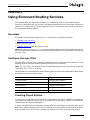
Using Eiconcard Routing Services ........................................................... 35
Overview ..................................................................................35
Configure the mpr.if file ..............................................................35
Load the mpr.if file .....................................................................38
Testing Your Installation ..............................................................40
Advanced Eiconcard Services Configuration .......................................... 53
Eiconcard Device Driver Parameters .............................................53
Eiconcard Advanced Driver Options Configuration ...........................54
Modem and Null-Modem Cables ................................................................ 55
Connecting Two Workstations ......................................................55
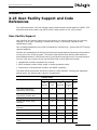
X.25 User-Facility Support and Code References ................................... 61
User-Facility Support ..................................................................61
Networks and DNICs ..................................................................68
X.25 Diagnostic Codes ................................................................69
X.25 Cause Codes ......................................................................71
ASCII Control Codes ...................................................................72
page 3
X.29 Call User Data Format ........................................................................ 75
Key Packet Formats .................................................................................... 77
Call Request Packet Format ......................................................... 77
Call Accepted Packet Format ....................................................... 78
Clear Request Packet Format ....................................................... 79
Clear Confirmation Packet Format ................................................ 80
X.3 PAD Parameters .................................................................................... 81
X.3 PAD Parameter Support ........................................................ 81
X.3 PAD Parameters ................................................................... 82
page 4
Eicon Connections for Linux User’s Guide
CHAPTER 1
About this Guide
The Eiconcard Connections for Linux User’s Guide provides information on how to configure
and use Eiconcard Connections for Linux. It includes the following sections:
Important: This document does not contain information on how to
install Eiconcard Connections for Linux. For installation information,
consult the Release Notes (ReadmeFirst.txt) located in the
Linux/SC_Series directory on the Universal Connections Suite CD.
1: About this Guide
Provides an overview of the Eiconcard Connections for Linux User’s Guide and describes the
typographic conventions used.
2: Introducing Eiconcard Connections for Linux
Introduces Eiconcard Connections for Linux and explains how it functions in different
communications environments.
3: Configuring Eiconcard Connections for Linux
Describes how to install the Eiconcard Services and Eiconcard Connections for Linux drivers
and how to configure their communications protocol software. For instructions on how to install
Eiconcard Connections for Linux, see the Eiconcard Connections for Linux Release Notes
(ReadmeFirst.txt) located in the Linux/SC_Series directory on the Universal Connections Suite
CD.
4: Using the Eiconcard Host PAD and Eiconcard Terminal PAD
Explains how to configure the Eiconcard Host PAD and Eiconcard Terminal PAD.
5: Using Eiconcard Routing Services
Explains how to use the Eiconcard Routing Services package. It provides the procedure for
testing sample X.25, PPP, Multilink PPP, and Frame Relay connections. This chapter also
explains how to use the connection backup feature.
6: Advanced Eiconcard Services Configuration
Describes how to configure the Eiconcard Streams Device Driver.
7: Modem and Null-Modem Cables
Provides tips on modem and modemless (null-modem) cables and connections.
8: X.25 User-Facility Support and Code References
Describes the optional network services known as User Facilities and provides the DNIC, X.25
cause and diagnostic codes, and ASCII codes used to specify the facilities.
page 5
About this Guide
9: X.29 Call User Data Format
Provides the format for the X.29 Call User Data.
10: Key Packet Formats
Provides the formats for all the key packet types.
11: X.3 PAD Parameters
X.3 PAD parameters set the guidelines for how the PAD deals with different terminal
emulations.
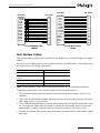
Typographic Conventions
This document uses the following typographic conventions:
Normal italic type is used for filenames, pathnames, and program names.
Mono-spaced type is used for commands and parameters.
Names of documents, sections, and chapters are enclosed in double quotes (“ ”).
This document uses the following syntax conventions for commands and parameters:
page 6
Convention
Purpose
ectest
Items set in mono-spaced type such as command names and parameters
must be entered exactly as shown. Note that Linux is case sensitive.
image
User-supplied items are set in mono-spaced italic type.
Enter
Keys to be pressed appear in boldface type.
[-v]
Items enclosed in brackets [] are optional. When an optional item is
included, it must be entered exactly as shown. Do not enter the square
brackets.
1|2|3
The vertical bar | separates two or more choices in a multi-valued
parameter. Choose only one value. Do not enter the vertical bar.
-t {A|B}
Braces {} enclosing a list of items separated by vertical bars (|) indicate
that you must select one item from that list. Enter the item exactly as
shown. Do not enter the braces or vertical bars.
Eicon Connections for Linux User’s Guide
CHAPTER 2
Introducing Eiconcard Connections for Linux
This chapter introduces Eiconcard Connections for Linux. It provides an overview of the
Eiconcard Connections for Linux architecture and describes the communications options it
offers. It also provides a brief description of Dialogic’s hardware solution—the Eiconcard—and
its supported communications protocols.
The Eiconcard Connections for Linux Solution
Eiconcard Connections for Linux allows you to:
• Connect a Linux server to local or remote systems over OSI-compliant connections such as
X.25, and supports a wide range of OSI communications services. These services include
management of communications links to local or remote systems, Packet
Assembler/Disassembler (PAD) support (X.3, X.28, and X.29), protocol processing for X.25,
HDLC (High-level Data Link Control), Frame Relay, SDLC (Synchronous Data Link Control)
and PPP (Point-to-Point).
• Link Linux application servers, with their associated TCP/IP LANs, over a wide-area network.
Eiconcard Connections for Linux integrates with the TCP/IP stack on your server, using the
Eiconcard to route IP traffic over X.25, Frame Relay, PPP, or MultiLink PPP connections to
remote TCP/IP hosts and networks.
Eiconcard Connections for Linux performs the processing required to pass IP datagrams
over WAN protocols, allowing a Linux server to connect with remote networks.
The Eiconcard Connections for Linux solution is composed of two components:
• The Eiconcard
An intelligent communications adapter used in all of Dialogic’s WAN connectivity solutions.
• The Eiconcard Connections for Linux software
Provides the protocol software, the Eiconcard driver, and the management utilities required
to set up your connections.
The Eiconcard
Dialogic’s Eiconcard is the hardware component of the Eiconcard Connections for Linux
solution. One or more Eiconcards can be installed in a Linux server. Each Eiconcard has its
own onboard CPU and memory, allowing it to run one or more communications stacks,
including X.25, Frame-Relay, SDLC (Synchronous Data Link Control), Point-to-Point (PPP) and
MultiLink PPP. A range of Eiconcards is available for different communications needs, such as
high-speed leased line connections, dial-up connections, or ISDN.
As the Eiconcard assumes all network-level protocol processing, the host Linux server’s CPU
can focus on application processing.
For a list of supported Eiconcards, consult the Eiconcard Connections for Linux Release Notes.
page 7
Introducing Eiconcard Connections for Linux
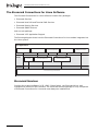
The Eiconcard Connections for Linux Software
The Eiconcard Connections for Linux software includes four packages:
• Eiconcard Services
• Eiconcard Host PAD and Terminal PAD Services
• Eiconcard Routing Services
• Eiconcard SNMP Services
And one sub-package:
• Eiconcard X.25 Application Support
The following diagram shows how the Eiconcard Connections for Linux module integrates into
the Linux system.
User Applications
Eiconcard Commands
Linux
Kernel
Host PAD Commands
Eiconcard Routing
Services
Third Party
Asynchronous Applications
Eiconcard HPAD Driver
Terminal PAD Commands
Applications based on
Dialogic X.25 Toolkits
Eiconcard TPAD Driver
Hardware
Eiconcard Running Protocol Stacks
Eiconcard Services
Provides the protocol software (X.25, HDLC, Frame Relay), the Eiconcard driver, and
management utilities for the Eiconcard. The Eiconcard Services package is a key component
of Eiconcard Connections for Linux and must always be installed first.
page 8
Eicon Connections for Linux User’s Guide
The Eiconcard Host PAD and Terminal PAD Driver
The PAD Driver architecture consists of the Host PAD and Terminal PAD drivers running on top
of the Eiconcard driver. These drivers fully emulate tty drivers, so any asynchronous application
written to tty driver standards can function with the Linux PAD drivers.
Eiconcard Host PAD Driver
The Eiconcard Host PAD driver allows remote users to access your Linux server over X.25
connections. Host PAD provides this functionality by implementing the X.3, X.28, and X.29
PAD standards. It therefore allows remote login by users on systems conforming to these PAD
standards over X.25. Host PAD provides the following capabilities:
• Each Eiconcard port can support multiple Host PAD sessions.
• The Eiconcard connects directly to the X.25 network, eliminating the need for asynchronous
modems and an external PAD.
• Remote login capability over highly-reliable X.25 communications links.
The Eiconcard Host PAD driver is a pseudo-driver linked into the Linux kernel. It uses the
services of the Eiconcard driver to access the X.25 protocol running on the Eiconcard. A Linux
login daemon such as getty provides incoming connections from Host PAD with a login shell
as if the connection were on a local terminal. The Eiconcard Host PAD driver also provides
Host PAD device-configuration utilities and files, and includes a driver-configuration utility
(Eiconcard Host PAD Driver Configuration option in eiconcfg).
Note: The Host PAD Driver only receives calls from remote PAD users, it does not initiate them.
The Terminal PAD driver initiates calls to remote hosts over an X.25 network.
Eiconcard Terminal PAD Driver
The Eiconcard Terminal PAD driver enables Linux server users to login to remote systems over
X.25. Each Eiconcard port supports multiple TPAD sessions. As with the Host PAD, the Terminal
PAD provides this functionality by implementing the X.3, X.28, and X.29 PAD standards. It
therefore allows local users to login to any remote systems that conform to these PAD
standards over X.25.
The Eiconcard Terminal PAD driver is a pseudo-driver linked into the Linux kernel. It uses the
services of the Eiconcard driver to access the X.25 protocol running on the Eiconcard. Linux
utilities such as cu and uucp run over the Terminal PAD driver to provide the local user with
terminal functionality. The Eiconcard Terminal PAD driver also provides Terminal PAD
device-configuration utilities and files, and includes a driver-configuration utility (Eiconcard
Terminal PAD Driver Configuration option in eiconcfg).
Note: The Terminal PAD driver only initiates calls from local session users, it does not receive
them. Use the Host PAD driver to receive calls coming in over an X.25 network.
page 9
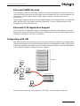
Introducing Eiconcard Connections for Linux
The diagram below illustrates how the Terminal PAD driver and Host PAD drivers are used in
a typical installation.
TCP/IP or SPX/IPX
network
Terminal
PAD
TPAD
Eiconcard
ASCII Terminals
telnet or nvt users
X.25 link
ASCII terminals use the Terminal PAD and
Eiconcard to access geographically
remote hosts concurrently.
X.25
Packet-Switched
Network
Public Database
Any ASCII Host
Eiconcard
DEC VAX
Host
PAD
Remote computers access the local
Linux system through the X.25
network, Eiconcard, and Host PAD.
Eiconcard Routing Services
Eiconcard Routing Services allows you to link Linux servers (Web, application, mail, etc.), with
their associated TCP/IP LANs, over a wide-area network. Routing Services integrates with the
TCP/IP stack on your Linux server, using the Eiconcard to route IP traffic over X.25,
Frame-Relay, Point-to-Point (PPP), or MultiLink PPP connections to remote TCP/IP hosts and
networks.
Routing Services performs the processing required to pass IP datagrams over WAN protocols,
allowing a Linux server to connect with other networks over a wide area.
page 10
Eicon Connections for Linux User’s Guide
Eiconcard SNMP Services
This package provides the necessary support for network management. It allows the user to
remotely control and monitor the Eiconcard Services components. As a remote manager you
can perform real-time administrative tasks, gather statistics, and track the router's
performance.
The package is composed of the Eiconcard SNMP Subagent, its configuration file, the supported
MIBs, and few HTML help pages providing information on how to setup and test remote
management of Eiconcard Services.
Eiconcard X.25 Application Support
The Eiconcard X.25 Application Support subpackage provides the functionality for running
applications, developed using the Eiconcard X.25 Development Tools (available separatly from
Dialogic® Corporation), over an X.25 network.
Integrating with OSI
OSI (Open Systems Interconnection) is a seven-layer hierarchical model for exchanging data.
OSI was developed by the International Organization for Standardization (ISO), with the goal
of defining, specifying, and relating communications protocols. OSI is a means of standardizing
communications between different computer systems.
Application Layer
Presentation Layer
Session Layer
Transport Layer
OSI Stack
Workstation
Network Layer
Data Link Layer
Physical Link Layer
LAN
Workstation
Eiconcard Connections
for Linux
X.25-Attached Host
X.25 Links
Workstation
Hildebrand
Eiconcard Connections
for Linux
Eiconcard Connections for Linux supports X.25, HDLC, and Frame Relay protocols.
page 11
Introducing Eiconcard Connections for Linux
OSI Support
Eiconcard Connections for Linux is implemented according to the OSI model. The top layer—
the Application Layer—is implemented by the PAD Support components or applications
developed using the Eiconcard Development Tools. The Network Layer and Data Link Layer
are implemented respectively by the X.25 and HDLC protocol support provided by the
Eiconcard Services package. The bottom OSI layer—the Physical Layer—is implemented by a
media connector on the Eiconcard.
The diagram below shows how Eiconcard Connections for Linux corresponds to the OSI network
model.
OSI Model
Application
Eiconcard Connections
for Linux
PAD Support Package /
Eiconcard Development Tool
Application
Presentation
Session
Transport
page 12
Network
Card Services-X.25
Data Link
Card Services-HDLC
Physical
Eiconcard
Eicon Connections for Linux User’s Guide
For More Information
The Eiconcard Connections for Linux Release Notes provides step-by-step instructions for
installing the Eiconcard Connections for Linux product.
The remainder of this user’s guide provides information on configuring and operating Eiconcard
Connections for Linux.
In addition to this user’s guide, the Eiconcard Connections for Linux software includes HTML
help pages that provide detailed information on the following:
• Eiconcard Services commands
• Eiconcard Host PAD commands
• Eiconcard Terminal PAD commands
• Eiconcard Routing Services commands
• Configuring the mpr.if file
• Configuring SNMPD agent
• Eiconcard Connections for Linux troubleshooting
• Glossary of terms and list of acronyms
The pages are located in the /docs subdirectory of the installation directory and can be viewed
using a Web browser.
page 13
Introducing Eiconcard Connections for Linux
page 14
Eicon Connections for Linux User’s Guide
CHAPTER 3
Configuring Eiconcard Connections for Linux
Installing/Removing Eiconcard Connections for Linux
This section describes how to install the Eiconcard Services and Eiconcard Connections for
Linux software.
Introduction
The Eiconcard Connections for Linux software is installed using rpm. You must be logged in
as ROOT in order to install and configure it.
Installing Eiconcard Services Software
It is recommended that the Eiconcard(s) be installed in your system before you install the
Eiconcard Services software.
Install the Eiconcard Services package as follows:
# rpm -ivh Eiconcard_Services-VvRr_xxxx-xx-xxx.xxxx.rpm
(replace 'v', 'r' and 'x' with corresponding numbers that appear in the file name; see the
description in "Section 3. Package Contents" in the file ReadmeFirst.txt)
This will create the /opt/dialogic/c4l directory that contains the Eiconcard Services software.
You can now configure the Eiconcard drivers and the WAN Protocols by executing
/opt/dialogic/c4l/eiconcfg.
Installing Eiconcard Routing Services
Install the Eicon Routing Services package as follows:
# rpm -ivh Eiconcard_Router-VvRr_xxxx-xx-xxx.xxxx.rpm
(replace 'v', 'r' and 'x' with corresponding numbers that appear in the file name; see the
description in "Section 3. Package Contents" in the file ReadmeFirst.txt)
Once this package is installed, additional services (Routing Services & Compression Modules)
will become available in the Eiconcard Services Protocol Configuration program.
To enable these additional services, run /opt/dialogic/c4l/eiconcfg, select option 2, then press
F4 to reach the Protocol Configuration panel.
Compression Modules must be enabled in order to use the PPP protocol; even if your connection
will not use compression.
Note that routing options are not configurable via /opt/dialogic/c4l/eiconcfg. There are two
methods that can be used to configure the routing services: ECCLI and Manual.
page 15
Configuring Eiconcard Connections for Linux
ECCLI Method
The Eiconcard Command Line Interface (ECCLI) application can be used to configure the
routing services and automatically generate the routing services configuration file (mpr.if).
Refer to the ECCLI documentation for details.
Manual Method
Optionally you can manually create and modify the mpr.if file in /opt/dialogic/c4l.
For details on the mpr.if file and how to configure a router for your Eiconcard(s), see the
documentation and samples. The top level of the documentation is located in
/opt/dialogic/c4l/docs/mprif.html.
Sample configurations are located in /opt/dialogic/c4l/mpr-if.
Note: If you edit the mpr.if file, it is recommended that you use the "vi" editor.
Installing Eiconcard PAD Services
Install the Eiconcard PAD Services package as follows:
# rpm -ivh Eiconcard_PAD_Services-VvRr_xxxx-xxx.xxxx.rpm
(replace 'v', 'r' and 'x' with corresponding numbers that appear in the file name; see the
description in "Section 3. Package Contents" in the file ReadmeFirst.txt)
This will install HPAD and TPAD. To configure TPAD and HPAD:
# cd /opt/dialogic/c4l
# ./eiconcfg
Select option 6: Configure PAD
The program used by PAD Services to dial in is mgetty.
You should modify the mgetty configuration file (/etc/mgetty+sendfax/mgetty.config) to
reflect your system's configuration.
For more information on configuring mgetty, consult your Red Hat/SuSE documentation.
Completing the Installation
You will need to reboot your PC to activate the new configuration.
Removing Eiconcard PAD Services
To remove Eiconcard PAD Services, do the following:
# rpm -e Eiconcard_PAD_Services
Removing Eiconcard Router
To remove the Eiconcard Router, do the following:
# rpm -e Eiconcard_Router
page 16
Eicon Connections for Linux User’s Guide
Removing Eiconcard Services
To remove the Eiconcard Services, do the following:
# rpm -e Eiconcard_Services
Manually removing /opt/dialogic/c4l (optional)
To completely remove all Eiconcard software and directories from your system after removing
the packages with "rpm -e ...", manually delete the /opt/dialogic/c4l directory as follows:
# rm -rf /opt/dialogic/c4l
Configuring Eiconcard Connections for Linux
This section describes how to install the Eiconcard Services and Eiconcard Connections for
Linux drivers in the kernel. It also describes as how to configure related communications
protocol software.
Introduction
Since Eiconcard Connections for Linux can interact with a wide variety of equipment, switches,
and networks, you should consult your network administrator for the correct configuration
settings to use. To simplify the configuration process, default values have been set for each
parameter, and in most cases it is not necessary to change them.
The eiconcfg program is used to install the Eiconcard Services and Eiconcard Connections for
Linux drivers in the kernel, and to configure related communications protocol software. The
eiconcfg program contains a number of different configuration screens that allow adjustment
of parameters in the following areas:
• Install an Eiconcard
• Uninstall an Eiconcard
• Modify Eiconcard Auto Load Configuration
• Configure Eiconcard Protocol
• Configure Advanced Options
• Configure PAD
Install an Eiconcard
Once the Eiconcard Services driver is installed in the Linux kernel, all supported Eiconcards
present in the system are automatically installed and configured by default to one port and
X.25 over HDLC (LAPB). However you may uninstall and re-install any supported Eiconcards
which are present in the system.
Follow these steps to reinstall a previously uninstalled Eiconcard:
1. Execute /opt/dialogic/c4l/eiconcfg
2. Select option 1, Add an Eiconcard.
page 17
Configuring Eiconcard Connections for Linux
3. Select the Eiconcard you wish to add from the displayed list of Eiconcards which are present
in the system but not installed. The status of Eiconcards which are not installed is listed
as UNINSTL.
4. Press Enter.
5. If you want to add another Eiconcard now, repeat steps 2-4. Otherwise, enter b to go back
to the main Eiconcard Configuration screen
Uninstall an Eiconcard
To uninstall an Eiconcard run eiconcfg and follow these steps:
1. Execute /opt/dialogic/c4l/eiconcfg
2. Select option 2, Uninstall an Eiconcard.
3. Select the Eiconcard you wish to remove from the displayed list of Eiconcards which are
currently installed.
4. Press Enter.
5. If you want to uninstall another Eiconcard now, repeat steps 2-4. Otherwise, enter b to
go back to the main Eiconcard Configuration screen.
6. The status of uninstalled Eiconcards will be changed to UNINSTL.
Modify an Eiconcard’s Auto Load Configuration
Follow these steps to modify an Eiconcard’s Autoload configuration:
1. Execute /opt/dialogic/c4l/eiconcfg
2. Select option 3, Modify Eiconcard Auto Load Configuration.
3. Select the number of the Eiconcard you wish to configure.
4. Enter Yes or No as desired, or press Enter to accept the default value. Press h to display
help information.
5. Press Enter to return to the card selection screen.
6. To modify another Eiconcard’s Auto Load configuration now, repeat steps 3-5. Otherwise,
enter b to go back to the main Eiconcard Configuration screen.
Configure Eiconcard Protocol
The Configure Eiconcard Protocol option is used to configure the communications protocol
software. It contains configuration screens that allow adjustment of parameters in the
following areas:
• High-Level Services
• Line Protocols
• Dialer Selection
The following sections provide guidelines for selecting options and adjusting parameters during
configuration. For detailed configuration procedures, see Configuration Procedure on page 21.
page 18
Eicon Connections for Linux User’s Guide
High-Level Services
Eiconcard Connections for Linux High-Level Services consists of the following options:
• Transport ISO
• Routing Services
• Compression Modules.
Follow these steps to configure the Eiconcard High-Level Services:
1. Execute /opt/dialogic/c4l/eiconcfg
2. Select option 4, Configure Eiconcard Protocols.
3. Press F4 to access the configuration screens.
4. Move the cursor to the desired High-Level Protocol and press the Spacebar to enable the
feature.
5. Press F4 to open the configuration screen for the selected High-Level Protocol.
6. Configure the displayed parameters as desired.
7. Press F3 to return to the main Configure Eiconcard Protocols screen.
8. Press F1 for on screen help at any time.
9. Press F2 to save the configuration.
10. Press F10 to exit the Configure Eiconcard Protocols screen.
11. Reload the Eiconcard(s) when prompted to activate the new configuration.
Line Protocols
Eiconcard Connections for Linux allows you to assign protocols on a per port basis. These
protocols are called line protocols, and they handle the actual data transfer. Eiconcard
Connections for Linux supports the following line protocols:
• X.25: An international standard for data communications and is supported in many countries
worldwide. Eiconcard Connections for Linux supports CCITT Recommendation 1984 for X.25
operations, over HDLC connections.
• HDLC: A data-link layer protocol used by X.25 to transmit information over a network. Most
applications interface at the X.25 level; however, HDLC is provided for custom applications
that require it.
• SDLC: A data-link layer protocol used by SNA to transmit information over a network.
• Frame Relay
• Point-to-Point Protocol (PPP), with an option to configure Multilink PPP.
Dialer Selection
Like other Dialogic® products, Eiconcard Connections for Linux supports a number of dialer
options:
• Direct (hardware dialer)
• Hayes AT (asynchronous dialer)
• V.25bis
• Bchannel
page 19
Configuring Eiconcard Connections for Linux
• SIG.+X.25
Choose one of these options based on the line type or modem being used.
Changing Protocol Parameters
Each protocol has a number of parameters associated with it. These parameters allow
customization of the protocol software for your particular connection. Eiconcard protocols can
be configured to suit almost any communications situation. This is done by assigning values
to the parameters in the protocol configuration screens.
Note: It is always a good idea to make a backup copy of your Eiconcard configuration file
ec.cfg before modifying any parameter values. If problems are encountered with the modified
version, the backup copy can be restored. As an aid for detecting communication problems,
log any changes you make to the original file.
Eiconcard Memory Requirements
The Eiconcard contains its own CPU, memory, and embedded operating system. The protocol
software runs on the Eiconcard, not on the Linux server. Therefore, the software options you
define for Eiconcard Connections for Linux are constrained by the amount of memory available
on the Eiconcard. This applies to protocols you define with eiconcfg or ECCLI and to the number
of Host PAD and Terminal PAD devices defined on the Linux system.
Using the Configuration Screens
The configuration screens all use specific function keys, which are listed at the bottom of the
screen. To move between parameters, use the cursor keys () or the Tab key. To change a
parameter, type the new value directly. For some parameters, you can press the Spacebar
repeatedly to scroll through the permitted parameter values.
The following table describes the function keys displayed on the configuration screens:
Alternative Function Keys
Most terminals have the function keys defined in /usr/lib/terminfo/terminfo.src.
If this is not the case, you should be able to use an alternative function-key mapping. For
example, the following function keys are normally available:
• Esc 1 Help
• Esc 2 Save
• Esc 3 Previous Screen
• Esc 4 Config
• Esc 5 Previous Card
• Esc 6 Next Card
• Esc 9 Print
• Esc 0 Quit
page 20
Eicon Connections for Linux User’s Guide
Note: If you are unable to use either set of function keys, consult the administrator’s guide
for your Linux operating system for information on keyboard mappings.
Function Key
Description
F1 Help
Provides information about the current screen and its parameters.
F2 Save
Saves the parameter values for all screens to the configuration file.
F3 Prev
Moves you to the previous configuration screen, if applicable.
F4 Config
Moves you to the next configuration screen, if applicable.
F5 PrvCrd
Moves you to the configuration screens for the previous card.
F6 NxtCrd
Moves you to the configuration screens for the next card.
F9 Print
Prints the configuration information to an ASCII file, using a .prt extension for the
filename.
F10 Quit
Exits the Eiconcard Services Protocol Configuration or Help screen.
Online Help
You can press the F1 Help key anywhere in the protocol configuration program for
screen-sensitive help. To see a description of parameters on a particular screen, move the
cursor to that screen and press F1 Help.
Detailed information regarding the selected screen will appear. Press the Page Down key to
see additional pages of information, or Page Up to see the previous page. Exit the Help page
using F10.
Accessing ISDN switch-specific online help
To access this information, follow these steps:
1. Access the Hardware Configuration screen and select your switch type.
For details on this and the other configurable parameters on the Hardware Configuration
screen, press F1.
2. Press F10 to quit the help screen.
3. Press F4 to access the Protocol Configuration screen. For the first port, Direct is
automatically selected as the Dialer Selection value. Move to this field and press the
Spacebar until Bchannel is selected. Press F4 to access the B-channel Configuration
screen.
4. Specify the Local Directory Number assigned by the telephone company. You cannot access
the online help until you have provided a value for this mandatory parameter.
Note: For the NI-1 switch type, you must also specify the Service
Profile Identifier (SPID) number before you can access the online help.
5. Press F1 for information on the available port configurations for your configured switch
type, as well as for information on the B-channel parameters specific to your switch type.
6. Press F10 to quit the help screen.
7. Press F3 to return to the Protocol Configuration screen and select B- channel, SIG.+X25,
or an HSI dialer type for the remaining port(s) as needed.
8. With SIG.+X25 selected (if supported by your subscribed switch type), press F4 to access
the D-channel Configuration screen.
page 21
Configuring Eiconcard Connections for Linux
9. Specify a value for the Static TEI parameter and press F1 for details on configuring the
D-channel to transfer X.25 packet data.
Note: For the NI-1 switch type, you must also specify the X.25 DTE address before you
can access the online help.
Configuration Procedure
The eiconcfg program stores most parameter settings in the Eiconcard configuration file. The
default name for this file is /opt/dialogic/c4l/ec.cfg.
The following steps outline the configuration process. References are made to several
configuration screens. For information on using configuration screens, see Using the
Configuration Screens on page 20.
1. Create a backup copy of the ec.cfg configuration file in case you need to restore the original
version. Whenever you save the ec.cfg file, its previous version is saved to ec.bak.
Subsequent saves will overwrite the backup file.
2. Select the Eiconcard Services Protocol Configuration option from the main eiconcfg menu.
3. Type the name of the Eiconcard configuration file that you want to modify and press Enter.
To see a list of available configuration files, type *.cfg and press Enter. Use the cursor
keys to highlight the file that you wish to configure and press F4.
4. If you want to save the *.cfg settings to an ASCII text file, select an Eiconcard configuration
file in the Files box and press the F9 Print key. The ASCII text filename is *.prt, so if the
configuration file was ec.cfg, then the ASCII text file will be saved to ec.prt in the current
directory.
5. Press F4 Config to display the Hardware Configuration screen.
6. Select appropriate values in the Number of ports and Auto activate ports fields for each
Eiconcard in your system. Use the Spacebar to scroll through the available options in each
box, and use the cursor keys (), Tab key, or Enter key to move between boxes. If you are
configuring more than one Eiconcard, move to the appropriate column to change the values
for each Eiconcard. If an entry you select is invalid, then that entry will flash until you
change it (on X-terminals, the incorrect entry is simply highlighted).
7. Press F4 Config to display the Protocol Configuration screen for the Eiconcard selected.
Note: If there is an invalid entry anywhere on the current screen, you cannot continue to
the next configuration screen. You can use F10 Quit or the Esc key to cancel the entire
configuration operation.
8. Move the cursor to the Line Protocol Module box, and press the Spacebar until you see
the option you want. Press F4 Config to configure that option. When you are finished,
press F3 Prev to return to the main Protocol Configuration screen.
9. To change the Dialer Selection, move the cursor to the Dialer Selection box, and press the
Spacebar until you see the option you want. Press F4 Config to configure that option.
10. If you have additional Eiconcards to configure, press F6 NxtCrd. The message "Card n"
appears in the top right corner of the screen. Configure each Eiconcard as you did the first
by modifying the necessary Line-protocol module and Dialer-selection parameters.
11. Press F2 Save to save all parameter settings for all cards to the Eiconcard configuration
file you selected on the Eiconcard Connections for Linux Protocol Configuration screen.
12. Press F10 Quit to exit the configuration program.
13. Reload the Eiconcard(s) when prompted.
page 22
Eicon Connections for Linux User’s Guide
14. Enter q to quit eiconcfg or, if you want to configure any of the Eiconcard Connections for
Linux drivers, do not quit eiconcfg now. Instead, proceed to the relevant configuration
section outlined in this chapter.
Configure Advanced Options
The default parameters for the Advanced Driver Options should be suitable for most user
systems. However, you may want to increase these values if your system includes multiple
applications written with the Eiconcard X.25 Development Kit.
To configure advanced Eiconcard options, run eiconcfg and follow these steps:
1. Execute /opt/dialogic/c4l/eiconcfg
2. Select option 5, Configure Advanced Options.
3. Select option 2 to keep the current configuration.
4. Select option 1 to modify the configuration.
5. Enter the driver parameters as prompted, or press Enter to accept the default value.
6. If you press H, help information will be displayed for each parameter.
7. After specifying a value for the last parameter, you will be returned to the Configure
Advanced Options screen.
8. Enter b to go back to the main Eiconcard Configuration screen.
Configure the PAD
To configure the Eiconcard PAD driver, run eiconcfg and select option 6, Configure PAD. The
displayed menu options are discussed in the following sections.
Configure Eiconcard Host PAD Driver
Follow these steps to configure the Eiconcard Host PAD driver:
1. Execute /opt/dialogic/c4l/eiconcfg
2. Select option 6, Configure PAD.
3. Select option 1, Eiconcard Host PAD Configuration.
4. Select option 1, Configure Eiconcard Host PAD Driver.
5. Enter the Eiconcard Host PAD Driver parameters as prompted, or press Enter to accept
the default values. You can display online descriptions of the driver’s parameters by
pressing h at each parameter’s prompt. After you specify a value for the last parameter,
the new configuration values are displayed and you are returned to the Configure Eiconcard
Host PAD Driver screen.
6. Enter q to return to the Eiconcard Host PAD Driver Configuration screen.
7. Enter q again to return to the main eiconcfg screen
Install/Remove Eiconcard Host PAD Driver
The Eiconcard Host PAD driver must be installed in the kernel before you can use the Eiconcard
Host PAD.
page 23
Configuring Eiconcard Connections for Linux
To install or remove the Eiconcard Host PAD driver, follow these steps:
1. Execute /opt/dialogic/c4l/eiconcfg
2. Select option 6, Configure PAD.
3. Select option 1, Eiconcard Host PAD Driver Configuration.
4. Select option 2, Install/Remove the Eiconcard Host PAD Driver, as desired.
5. Select an option or press Enter to continue.
6. Enter q to return to the Eiconcard Host PAD Driver Configuration screen.
7. Enter q again to return to the main eiconcfg screen
Configure Eiconcard Terminal PAD Driver
Follow these steps to configure the Eiconcard Terminal PAD driver:
1. Execute /opt/dialogic/c4l/eiconcfg
2. Select option 6, Configure PAD.
3. Choose option 2, Eiconcard Terminal PAD Driver Configuration.
4. Select option 1, Configure Eiconcard Terminal PAD Driver.
5. Enter the Eiconcard Terminal PAD driver parameters as prompted, or press Enter to accept
the default values. You can display online descriptions of the driver’s parameters by
pressing h at each parameter’s prompt. After you specify a value for the last parameter,
the new configuration values are displayed and you are returned to the Configure Eiconcard
Terminal PAD Driver screen.
6. Enter q to return to the Eiconcard Terminal PAD Driver Configuration screen.
7. Enter q again to return to the main eiconcfg screen
Install/Remove Eiconcard Terminal PAD Driver
The Eiconcard Terminal PAD driver must be installed in the kernel before you can use the
Eiconcard Terminal PAD.
To install or remove the Eiconcard Terminal PAD driver, follow these steps:
1. Execute /opt/dialogic/c4l/eiconcfg
2. Select option 6, Configure PAD.
3. Select option 2, Eiconcard Terminal PAD Driver Configuration.
4. Select option 2, Install/Remove the Eiconcard Terminal PAD Driver, as desired.
5. Select an option or press Enter to continue.
6. Enter q to return to the Eiconcard Terminal PAD Driver Configuration screen.
7. Enter q again to return to the main eiconcfg screen.
page 24
Eicon Connections for Linux User’s Guide
CHAPTER 4
Using the Eiconcard Host PAD and Eiconcard
Terminal PAD
This section explains how to prepare and test the Eiconcard Host PAD devices and includes
the available stty settings for the Eiconcard Host PAD tty devices and their equivalent X.3 PAD
parameters. It also provides information on configuring the Eiconcard Terminal PAD using the
cu and uucp commands.
For more information on X.3 PAD parameters, see X.3 PAD Parameters on page 81.
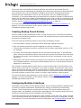
Quick Reference
The following list is a quick reference of Eiconcard Host PAD and Eiconcard Terminal PAD
commands:
Displaying Status Information
hpad -h
hpad [-a][-v]
hpad [-v][devicename ...]
tpad -h
tpad [-v][devicename ...]
Loading Configuration Information
hpadcfg -h
hpadcfg [-v] [devicename ...]
hpadcfg [-p port][-a DTE][-f facility][-u userdata]
[-C cfgfile] devicename ...
tpadcfg -h
tpadcfg [-p port][-l profile][-A tpaddir_entry] [-N][-L|-R]
[-C cfgfile] devicename ...
Restoring Status
hpadload -h
hpadload [-t|-c] [-C cfgfile]
tpadload -h
tpadload [-c][-t {c,d,p}][-C cfgfile][-D dirfile][-P profile]
Maintaining Calling Directory
tpaddir -h
tpaddir [-a called_DTE][-l local_DTE][-f facilities]
[-u userdata][-x parameters][-D dirfile][name...]
tpaddir -r [-D dirfile] name...
page 25
Using the Eiconcard Host PAD and Eiconcard Terminal PAD
Maintaining X.3 Parameter Profiles
tpadprof
tpadprof
tpadprof
tpadprof
-h
[name...]
[-x parameters][-s comment][-P profile][name...]
-r [-P profile] name...
Information about all of these commands are available online. For information on how to
access these commands, using an HTML browser, see For More Information on page 13.
Configuring Eiconcard Host PAD Devices
Once the Eiconcard Host PAD driver has been installed and configured, it may be necessary
to change the setup of the various Eiconcard Host PAD tty devices. In most cases, the default
setup for the Eiconcard Host PAD devices should suffice. The following steps describe how to
change the default terminal type and parity settings:
1. Login as root.
2. When Eiconcard Host PAD was installed, a line was added to /etc/inittab for each device.
The /etc/inittab file contains these lines:
Et00:2345:off:/sbin/getty
Et01:2345:off:/sbin/getty
Et02:2345:off:/sbin/getty
Et03:2345:off:/sbin/getty
Et04:2345:off:/sbin/getty
Et05:2345:off:/sbin/getty
Et06:2345:off:/sbin/getty
Et07:2345:off:/sbin/getty
ttyEt00
ttyEt01
ttyEt02
ttyEt03
ttyEt04
ttyEt05
ttyEt06
ttyEt07
hpad_8n
hpad_8n
hpad_8n
hpad_8n
hpad_8n
hpad_8n
hpad_8n
hpad_8n
This example assumes that you are installing the eight default Host PAD devices.
The Eiconcard Host PAD devices need to be enabled before you can use them. Set the
action field from ‘off’ to ‘respawn’ or similar. See the inittab man page.
3. If you need more than one Eiconcard Host PAD device configuration, add entries to the
/etc/gettydefs file. When the Eiconcard Host PAD was installed, a default setup for its
device was added to the /etc/gettydefs file with the following line:
hpad_8n# B9600 SANE HUPCL # B9600 CS8 SANE HUBCL TAB3 ECHOE IXANY \
#login: #hpad_8n
This line defines communications features such as baud rate and parity settings for the
Eiconcard Host PAD. This default gettydefs or ttydefs definition sets the Eiconcard Host
PAD to “8-bit none, no strip of parity,” which satisfies the needs of most installations.
However, you may want to construct your own gettydefs definitions and assign them to
unused codes. For details and instructions, see your Linux system administrator’s
documentation or the gettydefs man page.
4. To complete the Eiconcard Host PAD device configuration, verify that settings in the mgetty
configuration file (/etc/mgetty+sendfax/megetty.config/megetty.config) match the
configuration of your system. The config file is grouped into port-specific sections,
separated by port <tty-name> lines. Everything before the first port line specifies global
defaults; everything between two port statements specifies configuration items valid only
for this device.
page 26
Eicon Connections for Linux User’s Guide
Testing Eiconcard Host PAD Devices
Once the system has been rebooted and is running in multi-user mode, you should test an
Eiconcard Host PAD connection as follows:
1. Load the Eiconcard manually if it is not already loaded:
# eccard start
2. Issue the eccard status and hpad commands to verify that the port(s) assigned to your
Eiconcard Host PAD tty devices are active. Use the hpadcfg -p command to reconfigure
the devices if necessary.
3. Using a text editor, edit /etc/inittab to enable the Eiconcard Host PAD tty devices. Enable
the devices by changing the off parameter on the desired Eiconcard Host PAD device lines
to respawn.
4. Use the init command to advise the system that /etc/inittab has been changed:
# init q
The Eiconcard Host PAD tty devices are enabled for this session only. Steps 2 and 3 must
be done each time you rebuild your kernel.
Note: Eiconcard Host PAD tty devices are disabled by editing /etc/inittab and changing the
Eiconcard Host PAD device respawn flags to off.
You can test both the Eiconcard Host PAD Driver and the Eiconcard Terminal PAD Driver by
connecting the two together over an actual X.25 network.
Two Eiconcards, or one multi-port Eiconcard, may be connected back to back, so that X.25
communications is used without the need for connection to an X.25 network. A null-modem
cable must be connected between the two ports. In addition, one port must be set up as DCE
with internal clocking and line speed set, and the other as DTE with external clocking.
Once the Eiconcard Host PAD driver is properly installed and at least one device has been
tested, the Eiconcard Host PAD tty devices are ready to be used. Several Eiconcard Host PAD
commands are provided for configuring Eiconcard Host PAD devices and checking their status.
For more information on these commands, see the online documentation. For information on
accessing online documentation, see For More Information on page 13.
stty/X.3 PAD Parameters
The Linux stty command allows the Eiconcard Host PAD to change the setup of the remote
Eiconcard Terminal PAD when the two are connected over an X.25 network.
Parity generation and checking is implemented in only the Eiconcard Host PAD driver. No X.29
packet is sent to the Eiconcard Terminal PAD to set parameter 21. If the terminal must use a
7-bit word size and even parity, set the Eiconcard Host PAD to use the stty settings cs7
parenb -parodd.
Using tpad with cu and uucp
This section provides information on the configuration of the Eiconcard Terminal PAD for use
by the Linux commands cu and uucp. Several examples that demonstrate the use of cu and
uucp for making calls to a remote system are also included.
page 27
Using the Eiconcard Host PAD and Eiconcard Terminal PAD
The Eiconcard Terminal PAD driver is used to make outgoing uucp calls. The uucp configuration
files must be set to your specific requirements before you make a call. For information on
configuring these files, see The uucp Configuration Files on page 31.
To modify the outgoing call, use tpaddir with a conn command or use the cu CALL command.
X.28 is a CCITT recommendation that defines the messages that a terminal can send to a
PAD. The X.28 PAD command signals may be entered in uppercase or lowercase. Before any
PAD command interpretation is performed, all control characters, including DEL and spaces,
are stripped from the editing buffer.
For uucp, the connection and login must be automated. When the PAD is started, the PAD
Identification PAD service signal is sent, followed by a prompt. The standard prompt is the
“*” (asterisk) character. The Prompt PAD service signal will be displayed if the initial PAD
parameter 6 has value 4 set (that is, equals 4 or 5). Therefore, the first Expect string is “*”.
The Send string should be a call request string that contains no intervening spaces.
Note: You can include spaces in a call request string if you enter them in hexadecimal or octal
format (e.g., a space is \040, the “C”-like escape sequence for octal 40).
The cu Commands
You can use the following cu commands with the configured Eiconcard Terminal PAD devices.
<empty line>
When a virtual call is established, a blank command line causes a return to the data transfer
state. Otherwise, the blank line is ignored.
Selection PAD command signal
The Selection PAD command signal syntax consists of a facility request block or an address
block, or both, optionally followed by a call-user data field.
This standard PAD command signal, defined in recommendation X.28-3.5.15, is not
implemented in this version of the PAD.
Note: The commands listed below are not case-sensitive. For example, you can enter the call
or CALL command.
call
The call PAD service signal provides the only outgoing call mechanism.
*call address [/facilities [/userdata]]
This establishes a call to the given X.25 address, with the specified facilities and call-user
data. Valid X.25 addresses are strings of 1 to 15 digits. Facilities are numbers from 0 to 255,
separated by commas. The facilities field may be empty, or contain up to 109 octets.
The call-user data is a set of numbers from 0 to 255, separated by commas and/or quoted
strings. If the call-user data field starts with a minus symbol (-), the standard PAD protocol
identifier 1,0,0,0 is suppressed in the call-user data. Up to 16 octets of call-user data are
allowed (including the PAD protocol identifier), but this maximum is 128 octets when used
with the fast select facility. If a virtual call is already established when this command is invoked,
the error message Already connected is displayed. This PAD command signal is provided as
an extension to the standard PAD functionality.
page 28
Eicon Connections for Linux User’s Guide
Examples
*call
*call
*call
*call
*call
324576
092341 /1,1
324543123 /1,0,2,1 /"login"
234512343 // "uucp"
34657332 /1,0 /-1,0,0,1,"bill"
clr
Clear virtual call. If no virtual call is established when this command is invoked, the error
message No connection is displayed.
*clr
conn name
Connect to given name. The name is a PAD directory entry that describes the called DTE, its
X.25 address, the facilities, the call-user data, and the X.3 parameters to be used (see the
tpaddir command online). This PAD command signal is provided as an extension to the
standard PAD recommendation.
*conn host1
Where host1 is defined by tpaddir. For example:
# tpaddir -a 1234 host1
exit, logout, quit
Exit PAD. This command forces the tty software to simulate a loss of carrier detect signal and
forces the Eiconcard Terminal PAD driver to read and write return zero (end of file). Ultimately,
all processes currently using the Eiconcard Terminal PAD will close the Eiconcard Terminal PAD
device file. This PAD command signal is provided as an extension to the standard PAD
recommendation.
*exit
id
Display PAD identification PAD service signal. The format of the message is:
tpad device profile profile port port
where device is a 1, 2, or 3-decimal-digit number representing the decimal value of the minor
device number; profile is the initial X.3 profile identifier for the device; port is the device’s
initial port number in decimal. This PAD command signal is provided as an extension to the
standard PAD recommendation.
*id
tpad 0 profile 'uucp'
int
Send interrupt packet. An interrupt data packet with one byte of call-user data set to zero is
sent over the X.25 virtual circuit. If no virtual call is established when this command is invoked,
the error message No connection is displayed.
*int
page 29
Using the Eiconcard Host PAD and Eiconcard Terminal PAD
port [port]
Set physical port. This command sets the physical port on which the communications will take
place. Normally, ports 1-255 are used. If you do not specify a port, the current port number
is displayed. To re-assign a port, include a decimal number with the port command. This PAD
command signal is provided as an extension to the standard PAD recommendation.
*port
1
*port 2
*port
2
prof [profile identifier]
Set X.3 Profile. Set the X.3 PAD parameter profile to that of the specified profile identifier. If
no profile identifier is specified, display the currently selected profile identifier. If the specified
profile identifier is not known, the error message Profile not found is displayed.
Three standard profiles are provided: uucp (default), 90, and 91. The following lists the PAD
parameter values for each of these profiles:
uucp: 1:1
2:1
4:0
5:0
6:5
7:4
8:0
9:0
10:0
11:2
12:0
3:126
13:0
14:0
15:1
16:8
17:21
18:18
19:2
20:0
21:0
22:0
90: 1:1
2:1
4:0
5:1
6:1
7:2
8:0
9:0
10:0
11:2
12:1
13:0
14:0
15:0
19:1
20:0
21:0
22:0
3:126
91: 1:0
2:0
3:0
10:0
11:2
12:0
13:0
4:20
19:1
20:0
21:0
22:0
5:0
6:0
14:0
15:0
16:127 17:24
7:2
8:0
16:127 17:24
18:18
9:0
19:18
*prof
90
*prof uucp
*prof
uucp
par? [par,par,...], par [par,par,...]
Display X.3 parameters. Display the current value of the specified X.3 PAD parameters. If no
parameter is specified, all parameters are displayed. If a specified parameter reference is
invalid, it is displayed with its value specified as inv. The two commands are treated identically.
The PAD command signal par is provided as an extension to the standard PAD
recommendation.
*par? 1,2,43,7
par 1:1, 2:1, 43:inv, 7:21
page 30
Eicon Connections for Linux User’s Guide
reset
Reset virtual circuit. If no virtual call is established when this command is invoked, the error
message No connection is displayed.
*reset
set [par:val,par:val...]
Set the specified X.3 PAD parameters (par) to the specified values (val). If no par:val is
specified, the PAD parameters are set to the value of the current profile identifier. If a specified
parameter reference and/or value is invalid, it is displayed with its value specified as inv.
*set 1:0,2:1
*set 1:1,2:3
par 2:inv
*set 2:0
set? [par:val,par:val...]
Set and display the specified X.3 PAD parameters (par) and values (val). If no par:val is
specified, the PAD parameters are set to the value of the current profile identifier. If a specified
parameter reference and/or value is invalid, it is displayed with its value specified as inv.
*set? 1:0,2:1
par 1:0, 2:1
*set? 1:1,2:3
par 1:1, 2:inv
*set? 2:0
par 2:0
stat
Display the status of the virtual call, which may be either engaged or free.
X.3 PAD Parameters
The uucp Standard profile (similar to the X.3 Standard profile) should be used when uucp
transfers are to be made with the Eiconcard Terminal PAD. In particular, the X.3 PAD parameter
12 must be zero (no flow control of the PAD by the start-stop mode DTE), otherwise the X-ON
and X-OFF characters will be interpreted by the PAD, making binary data transfer impossible.
You may need to modify some of the PAD parameter values. With the exception of timer
expiration (4:1), the PAD parameters should be set so that no data interpretation is done.
The Recall character should be zero (1:0), Echoing off (2:0), no data forwarding character
(3:0), no special character insertion (10:0, 13:0), no editing (15:0), no page wait (22:0).
Hosts to which the Eiconcard Terminal PAD connects should send the appropriate X.29 set or
set and read PAD messages when the tty mode is changed from canonical mode to raw mode.
See your Linux documentation for a description of the stty command.
The uucp Configuration Files
You must set up the configuration for your Eiconcard Terminal PAD devices before you can
use them. To do this, you add or edit appropriate entries in the uucp configuration files. This
must be done before calls are made with the Eiconcard Terminal PAD.
page 31
Using the Eiconcard Host PAD and Eiconcard Terminal PAD
Examples are used to help clarify how these uucp configuration files are used. Names and
other user-supplied items are chosen arbitrarily. To run these examples on your system, choose
user-supplied names and items that are defined for your system.
The uucp configuration files are usually located in the /etc/uucp directory. Check your Linux
documentation on uucp for the correct path on your system. There are several uucp
configuration files including call, dial, dialcode, passwd, port, and sys. The example below
uses the sys and port files.
Sys
In the sys file, add entries to define your connections. In the example below, the entry defines
a uucp connection via the PAD. The connection is named ‘pad’ and can be called at “any’ time
using a device type of ‘tpad’ at speed ‘38400’. This entry may be used with cu or an interactive
terminal-emulation program when direct user interaction is desired with the PAD.
system pad
time any
port tpad
speed 38400
Port
In the port file, add entries for each terminal tty line device.
port tpad
type direct
device /dev/tpadEt00
speed 38400
Using uucp and cu
uucp implementations are very flexible. They can be customized to suit the various types of
line connections and modems you use for uucp communications. Before running this example
on your system, the uucp configuration files must be set up according to specific requirements.
In the following examples, “#” is the system prompt, “*” is the Eiconcard Terminal PAD prompt,
and “$” is the remote system prompt.
Note: Verify that you have correctly configured the Eiconcard Terminal PAD device(s) before
attempting to establish a connection. For example, you may need to assign ports using the
tpadcfg -p command.
Example 1
Use the cu utility to login to a remote system. The pad entry of the Systems file connects you
to the Eiconcard Terminal PAD. You may then call a remote system over an X.25 network:
# cu pad
// Connect to Terminal from system prompt
Connected
tpadEt 0 profile uucp port 1
*
page 32
// Now in Terminal PAD
Eicon Connections for Linux User’s Guide
*call 1302056300026
// Call remote system
or use
*conn host1
//host1 must be have been previously
defined using the tpadddir command
*
Connected
// Connected to remote system
Welcome to ...
login: xxxxx
// Login to remote system
password: *****
$
// Now in remote system
$...
$...
// Perform desired work
$...
$ logout
// Log out
CLR CONF
*
// Now back in Terminal PAD
*exit
// Return to system
*
Lost Carrier
Disconnected
#
// Now back at system prompt
page 33
Using the Eiconcard Host PAD and Eiconcard Terminal PAD
page 34
Eicon Connections for Linux User’s Guide
CHAPTER 5
Using Eiconcard Routing Services
This section describes the steps necessary for establishing routes in Eiconcard Routing
Services. It describes the key protocol configuration parameters for Eiconcards, and tests a
sample X.25, Frame Relay, PPP, and Multilink PPP link. This chapter also explains how to use
the connection backup feature.
Overview
To operate Eiconcard Routing Services, you must perform the following tasks:
• Configure the mpr.if file
• Start your Eiconcard
• Load the mpr.if file and start your circuits
Note: You must have run the eiconcfg program and configured the Eiconcard Services driver,
the Eiconcard Services protocols, and the Eiconcard Routing Services driver before configuring
the mpr.if file.
Configure the mpr.if file
The mpr.if file is an ASCII file, located in /opt/dialogic/c4l, in which the circuit entries for each
Routing Services interface and the packet filtering rules are defined.
Note: The mpr.if file is the default file for Eiconcard Routing Services, but you can create and
name your own *.if file, if required.
Sample files are provided with Eiconcard Routing Services which are configured for both simple
and advanced connections as follows:
Connection Type
Sample File
X.25 Connection
sys1x25.if and sys2x25.if
Frame Relay Connection
sys1fr.if and sys2fr.if
PPP Connection
sys1ppp.if and sys2ppp.if
PPP Connection with PAP and CHAP
sys1pap.if and sys2pap.if
Multilink PPP Connection
sys1mlp.if and sys2mlp.if
Creating Circuit Entries
A circuit entry is the definition of a virtual circuit that will be used to establish a subnetwork
connection. To establish a circuit entry, you create the circuit entry, name it, and define the
IP address of its first-hop destination.
A circuit entry defines the parameters necessary for the subnetwork connection, such as the
destination address and the port to use. For example, you can specify a remote DTE, facilities,
and user data for an X.25 circuit, whereas you specify a DLCI for a Frame Relay circuit.
page 35
Using Eiconcard Routing Services
The circuit entries you define for Routing Services are bound to the Routing Services
call-directory entries, depending on availability. Only when the circuit entry is associated with
a call-directory entry can you attempt to establish a connection. Routing Services then
allocates an open subnetwork circuit to the call-directory entry as needed during the
connection. It is recommended that you match both the maximum number of call-directory
entries and the maximum number of subnetwork circuits to the number of connections that
you plan to have. For more information on configuring call-directory entries and subnetwork
circuits, refer to Configuring Eiconcard Connections for Linux on page 15.
For more information about creating circuit entries, refer to Testing Your Installation on
page 40. For more information on the options used for creating circuits, consult
/opt/dialogic/c4l/docs/mprif.html.
Creating Backup Circuit Entries
You can create primary and backup circuits, so that if the primary circuit fails, the backup
circuit will ensure that the connection is not lost. The backup connection remains inactive until
the primary connection fails.
You must meet the following criteria to use primary and backup circuits:
• You must define a primary connection before defining a backup connection.
• Only one backup connection may be assigned per primary connection.
• The primary and backup connection must both use the same subnetwork protocol—X.25,
for example.
• A primary connection and its backup can use the same Eiconcard port, or two different
ports. If they use two different ports, both ports must be part of the same Eiconcard. Only
the logical connection is being backed up when the primary and backup circuits use the
same port.
• Backing up a PPP (point-to-point) connection or a permanent X.25 connection requires the
use of separate ports for the primary and the backup circuit. It is the physical link that is
backed up in these cases.
The connection backup feature works when it is used on both sides of the connection. You
cannot back up only half of a connection. If you back up system A’s connection (the circuit it
uses to connect to system B), system B’s connection to system A (the circuit configured on
system B) must also be backed up. To properly back up a connection between two systems,
you must configure a total of four circuits: a primary, and a backup on both systems.
For more information about backing up circuit entries, refer to Testing Your Installation on
page 40. For more information on the options used for creating circuits, consult
/opt/dialogic/c4l/docs/mprif.html.
Configuring Multiple Interfaces
Routing Services provides up to five WAN interfaces. These interfaces enable the establishment
of routes to multiple subnetworks simultaneously, offering a complete internetworking
solution. The five interfaces are configured in the mpr.if file. Each interface requires an
interface name, an IP address, and a network mask address. The interface names eic0 to eic4
identify the five Routing Services interfaces used by Dialogic.
A symbolic name can also be configured for each interface in the mpr.if file, which is stored
in the /etc/hosts file and can be used when specifying entries for the IP-routing table, though
this is optional. For more information on the IP-routing table, see IP Routing Tables on page 38
page 36
Eicon Connections for Linux User’s Guide
Configuring Packet Filtering Rules
When Routing Services receives an IP datagram over an interface, it checks the configured
packet filtering rules, and transparently forwards or drops the datagram based on these rules.
It is important to note that adding packet filtering will affect the performance of Eiconcard
Routing Services. As each IP datagram has to be tested against all of the defined packet
filtering rules, the datagrams will be delayed. It is therefore recommended to keep the number
of defined rules to a minimum and to make the rules as simple as possible.
Note: If no packet filtering rules are defined, all packets are forwarded by default.
Creating Packet Filtering Rules
Packet filtering allows you to determine what type of IP traffic can pass through your WAN
connections. You can control access to and from specific services, hosts, or networks. The
syntax for configuring packet filtering rules is given below with a detailed explanation of the
available options:
Syntax
filter [-saddr source_addr addr_mask]
[-daddr dest_addr addr_mask][-prot IP_protocol]
[-sport [source_port]][-dport [dest_port]]
in|out|both drop|forward
Parameters
Description
-saddr
source_addr
addr_mask
Specifies the source address and address mask for which you are
specifying a packet filtering rule. All packets with a source address
that match an address specified in the packet filtering rules will be
either forwarded or dropped.
-daddr
dest_addr
addr_mask
Specifies the destination address and address mask for which you
are specifying a packet filtering rule. All packets with a destination
address that match an address specified in the packet filtering rules
will be either forwarded or dropped.
-prot
IP_protocol
Identifies the Transport Layer Protocol for which a packet filtering
rule is being specified. The protocol field of the IP datagram specifies
the Transport Layer Protocol encapsulated in the IP datagram. All
packets with a Transport Layer Protocol that match a protocol
specified in the packet filtering rules will be either forwarded or
dropped. TCP and UDP are currently the only Transport Layer
Protocols that support source and destination port checks (see
/etc/protocols).
-sport
[source_port]
Specifies the source port for which you are specifying a packet
filtering rule. All TCP/IP protocols use addresses, known as ports,
that are used to uniquely define services (access points to the
Transport layer) at the Transport layer (see /etc/services). For
example, all ftp connections to a host are directed to port number
21; this way the receiving host knows to send the request to the ftp
service and not to the telnet service. All packets with a source port
that match a port specified in the packet filtering rules are either
forwarded or dropped. A source port is specified to prevent access
to certain services or applications on a local system by remote hosts.
This option must be enclosed within the brackets and port ranges
must be specified numerically.
page 37
Using Eiconcard Routing Services
Parameters
Description
-dport
[dest_port]
Specifies the destination port for which you are specifying a packet
filtering rule. All packets with a destination port that matches a port
specified in the packet filtering rules are either forwarded or
dropped. A destination port is specified to prevent access to certain
services or applications on a remote system by local hosts. This
option must be enclosed within the brackets.
in|out|both
Specifies whether a rule should be executed on receipt of a packet
from an Eiconcard, prior to being sent out over the Eiconcard, or
both. All rules should be executed on receipt of a packet,
guaranteeing that a packet is validated prior to being received by
IP. However, as packets cannot be validated on being received over
non-Eiconcard interfaces (i.e. LAN card), the facility will be available
to validate these packets prior to being sent out over Eiconcard
controlled interfaces.
drop|forward
Specifies whether a packet should be dropped or forwarded based
on the configured packet filtering rules.
For more information on the options available for configuring packet filtering rules, consult
/opt/dialogic/c4l/docs/mprif.html.
Load the mpr.if file
Once the mpr.if file is configured, it must be loaded down to the Eiconcard Routing Services
driver. Before doing this, you must ensure your Eiconcards are started using the eccard start
command.
Once your Eiconcards are started, run mprload at the command line to load the mpr.if file,
and mprstart to start your configured circuits.
The following commands are available with Eiconcard Routing Services:
• mprload: Loads the default mpr.if file down to the Eiconcard Routing Services driver.
• mprstart: Starts the circuits created with Eiconcard Routing Services
• mprstop: Stops the circuits created with Eiconcard Routing Services
• mprstat: Displays the status of the configured circuits or packet filtering rules
• mprauto: A script file that can be used to load and start your circuits automatically when
the system is started.
For more information on these commands, refer to the appropriate HTML page located in the
/opt/dialogic/c4l/docs directory.
IP Routing Tables
You can add IP-routing entries by using the Linux route command or the TCP/IP routing
daemon, routed. Entries you add with route are static. The routed daemon uses TCP/IP’s
Routing Information Protocol (RIP) to exchange information and update the routing table
entries.
page 38
Eicon Connections for Linux User’s Guide
When you use the route command, entries are added directly to a host’s IP-routing table,
but will be lost when the system shuts down. If you are setting up a complex network, it is
recommended that you use the TCP/IP routing daemon, which is initialized with the entries
stored in the host’s /etc/gateways file. The routed daemon manages both static and dynamic
routes, updating all hosts and gateways in the network automatically.
Note: Although using TCP/IP routing is necessary in the case of LAN-to-LAN connections, it is
not required when data is being transmitted only between Eiconcard Routing Services
workstations.
Each Linux host on a broadcast network sends out its accessible routes (using a routing
protocol, such as RIP) and keeps track of what other hosts it can access. Each host has an
IP-routing table, and the routed daemon handles all exchanges of routing information.
Adding Routing Table Entries to the /etc/gateways File
The routed daemon references the /etc/gateways file to identify a system’s routes. Route
entries listed in this file are installed in the system’s IP-routing table in the kernel at startup.
The syntax for Eiconcard entries in /etc/gateways is as follows:
Syntax
[net|host] addr1 gateway addr2 metric n [passive|active]
Parameters
Description
[net|host]addr1
If the IP route destination is a network, use net as the first
parameter, followed by the network’s address, addr1. If the
IP route is for a connection to a stand-alone host, use host
addr1. The network address must always be specified in full;
/etc/gateways does not accept abbreviated addresses. For
example, the 192.1.100 network address must be specified
as 192.1.100.0.
gateway addr2
Specifies the address of the first hop leading to the destination
network.
metric n
Identifies the total number of gateways through which data
must pass to reach the final destination.
[passive|active]
If you want routed to include the destination network or host
in its information broadcasts for the routing tables, specify
active. TCP/IP’s Routing Information Protocol (RIP) dictates
that hosts exchange information every 30 seconds and have
a 3-minute cache. This means that if a host has not heard
from another host for 3 minutes, it marks that host’s routing
table entry for deletion. After another 60 seconds, the table
entry is deleted.
With X.25-switched subnetworks, this information exchange
can be costly in terms of tariffs and the amount of bandwidth
used. If you want to include a circuit’s route in the Linux
systems but do not want its entry being constantly updated
or marked for deletion, specify passive. A connection can then
be made using the route, even though hosts in the system
are not notified of any changes in connection hosts’ status
(for example, if either the local host or the connection’s
destination host goes down).
For example, if Sys-2 (IP address 192.1.100.2) is connected to a network (IP address
192.218.20.0), the /etc/gateways file for Sys-1 could include the following entry to identify
a connection to that LAN:
net 192.218.20.0 gateway 192.1.100.2 metric 1 active
page 39
Using Eiconcard Routing Services
In this case, Sys-2 functions as a gateway to the 192.218.20 network.
Make sure each routing table entry you add to a host’s /etc/gateways file is correct before
adding another entry. You may want to test the route connection, as routed will not inform
you of any errors in /etc/gateways, such as an incorrectly specified IP address.
Note: If changes are made to the /etc/gateways file, the routed daemon must be restarted
with the -s option.
Displaying IP-routing Entries
You can use the netstat command to display information related to the IP routing tables. The
-i option displays information concerning the interfaces for entries in your system’s IP-routing
table, and the -r option presents the static and currently active routing entries.
You can also use the -n option to specify the use of dot notation. Addresses displayed by
netstat are then numeric values, rather than the symbolic names assigned by the /etc/hosts
file. (If an address does not have an assigned name in /etc/hosts, the netstat command
displays the numeric value.)
For example, the following commands show the entries you would see after adding the sample
entry to Sys-1’s /etc/gateways file, assuming the routed daemon had been reinitialized and
the route connection had been used to send and transmit data:
netstat -r -n
Routing tables
Destination
Gateway
Flags
Refcnt
Use
Interface
127.0.0.1
127.0.0.1
UH
1
0
lo0
192.1.100
192.1.100.2
U
2
392
eic0
192.218.20
192.1.100.2
UG
2
392
eic0
netstat -i
Name Mtu
Network
Address
Ipkts
Ierrs Opkts Oerrs Collis
lo0
2048
loopback
localhost
24
0
24
0
0
eic0
1500
192.1.100 192.1.100.2 4
0
410
0
0
The interface name eic0 identifies the Eiconcard Routing Services interface used by Dialogic.
The interface name lo0 is the default IP interface that enables the host to send or transmit
data to itself.
Note: Refer to the Linux system administrator documentation for more information on IP
routing if necessary.
Testing Your Installation
If you have at least two Linux systems that have an Eiconcard and Eiconcard Routing Services
installed, consider setting up a simple test system as suggested here. This will help you over
some of the initial hurdles inherent in dealing with internetworks and routers. Only two Linux
systems are used in this test system. You may add additional systems to test more complex
configurations.
page 40
Eicon Connections for Linux User’s Guide
You may assign your own IP addresses for this test, but it is recommended that you use the
IP addresses suggested in Resources for the Test System below.
The Test System
The test system described here links two Linux systems together back to back through their
Eiconcards. This procedure also tests the connection backup feature. Although this setup
cannot be considered an internetwork, it tests the Eiconcards’ transmission and reception of
IP datagrams over an X.25, Frame Relay, PPP, or Multilink PPP link.
To simplify the discussion below, the names Sys-1 and Sys-2 are used to identify the two test
systems.
Resources for the Test System
If you performed the installation as described in the Eiconcard Connections for Linux Release
Notes (Readmefirst.txt), you now have a Linux system (Sys-1) made up of the following:
• Hardware
• i386-based or higher Linux system
• An Eiconcard
• Software
• Linux
• Eiconcard Services package
• Eiconcard Routing Services package
A null-modem RS-232 cable or V.35 cable is also required.
To perform the tests, you will need to set up a second system (Sys-2) that is equivalent to
the first. Each system must be uniquely addressed.
Before continuing, make sure that the complete installation procedure has been performed
for Sys-1 and Sys-2.
When both the installations are complete and the systems rebooted, messages referring to
the Eiconcard, the Eiconcard Streams Device Driver (Eiconcard Services package), TCP/IP,
and Eiconcard Routing Services appear in the Linux boot messages.
The Addressing Scheme
Before continuing with the test, you should take a look at the proposed addressing scheme.
Both IP addresses and X.25 DTE addresses (for the X.25 connection) must be considered when
coming up with an addressing scheme for an IP internetwork that uses Eiconcard Routing
Services.
In this simple test the scheme uses an arbitrary assignment of four addresses—two X.25 DTE
addresses (for the X.25 connection), and the two IP addresses. The addresses used in this
test are:
Address
Sys-1
Sys-2
X.25 DTE address
3020001
3020123
IP address
192.1.100.1
192.1.100.2
page 41
Using Eiconcard Routing Services
To test the back-to-back connection, including the connection backup feature, you need to
configure the two Eiconcards, define an Eiconcard Routing Services circuit on each system,
define the destination IP addresses for the circuits on each system, and define the backup
circuits on each system before you can transmit data using the connection.
Configuring the Eiconcards
The Eiconcards installed in Sys-1 and Sys-2 must have several configuration parameters
changed so that back-to-back X.25 communications may be established.
To configure the Sys-1 and Sys-2 Eiconcards, select the Eiconcard Services Protocol
Configuration option in eiconcfg. For a description of eiconcfg, refer to Configuring Eiconcard
Connections for Linux on page 17.
When you select the Eiconcard Services Protocol Configuration option in eiconcfg for the first
time, or if the Eiconcard configuration file ec.cfg has been removed, you are notified that a
new ec.cfg file is being created. The default parameters for all screens related to the protocols
selected on the Protocol Configuration screen are saved in the newly created ec.cfg file.
Start with a default configuration. (You can keep a backup copy of your current configuration
by moving or renaming /opt/dialogic/c4l/ec.cfg.) Select the Eiconcard Services Protocol
Configuration option in eiconcfg on both Sys-1 and Sys-2 and set the parameters as indicated
in the following steps:
1. Move to the Protocol Configuration screen. Select Routing Services. The default values for
the Line protocol module and Dialer selection, X.25 and Direct, are the values required for
both systems.
2. Move to the Routing Services Configuration screen and set the Maximum number of
connection manager sessions to 2, one for the primary circuit and one for the backup
circuit (one per Eiconcard port).
3. Verify that the Maximum number of call-directory entries and Maximum number of open
subnetwork circuits parameters are both set to at least 2, one for the primary circuit and
one for the backup circuit (the default is 4 in both cases).
4. Move to the X.25 Configuration screen. For Sys-2 select DCE as the Node type and specify
3020123 as the Node address. Leave Sys-1 configured as DTE and specify 3020001 as
the Node address.
The HDLC Configuration screen for Sys-2 is automatically updated to reflect the change
from DTE to DCE.
5. Access the Sync Driver Configuration screen (via Dialer selection) and set Clocking to
Internal for Sys-2. Sys-1 keeps the Clocking default, External.
Note: If you choose to name your ports on the Sync Driver Configuration screen, the
names, rather than the port numbers, will be displayed when you use the mprstat
command.
6. On the same screen, you can set Line speed (bps) up to 64000 for Sys-2, provided you
are using a maximum length of 8 feet for the RS-232 cable that will connect the two
Eiconcards back to back.
7. Once the parameters are set, press F2 Save and F10 to exit. The two ec.cfg files are now
configured for Sys-1 and Sys-2’s back-to-back connection.
8. If the Eiconcard is already loaded and running (using eccard start), run eccard stop
to stop it.
9. Connect the Eiconcard in Sys-1 to the Eiconcard in Sys-2 with an RS-232 null-modem cable.
page 42
Eicon Connections for Linux User’s Guide
10. Run eccard start on both systems. The Eiconcards on each system are loaded and
configured according to the parameters found in their ec.cfg file.
Once eccard start has run successfully (no errors reported), you can use ecstatus to check
the integrity of the connection between Sys-1 and Sys-2.
Note: If you start the DTE first, it will report an error even though the connection will be
properly set up once you start the DCE. To avoid this temporary error condition, start the
system configured as DCE (Sys-2) first.
Creating an X.25 Test Circuit
After Sys-1 and Sys-2 are properly connected, an X.25 circuit must be created on each system.
Two sample files, sys1x25.if and sys2x25.if, are provided with Routing Services which are
configured for the purpose of running this test.
Note: Circuit names need only be unique within one Linux system; you can specify the same
name for the test circuits used on Sys-1 and Sys-2.
Once the circuits are created on both systems, ensure the Eiconcards are already started, and
run mprload -f sys1x25.if on Sys-1 and mprload -f sys2x25.if on Sys-2. This loads the
specified interface file down to the Eiconcard Routing Services driver. If the -f option is not
specified, the default file mpr.if is loaded down to the driver.
Run mprstart to start the circuits. If you stop an Eiconcard after creating a circuit entry, use
mprstart to restart the circuit once you have restarted the card.
Checking the Status of the X.25 Circuit
To check the status of your X.25 circuit, follow these steps:
1. Run ecstatus hdlc on both systems to confirm that the link between Sys-1 and Sys-2 is
operational. The Line State and Protocol State items appearing in the ecstatus display
should be listed as “Opened” on both systems.
2. Run ecstatus x25 on both systems to confirm that the link between Sys-1 and Sys-2 is
operational. The Link activated at item in the ecstatus display should list the time at which
the Eiconcards were started on each system.
Check that the circuit is correctly defined on both systems and that they are bound by
using the mprstat -c command. The systems display the following:
[Sys-1]# mprstat -c
cctname Subnet
Flags
Port
Comp
Parameters
x25test
1
TB
1
Off
RDTE:30201 192.1.10
23
0.2
eic0
I/F
X.25
First Hop
I/F
[Sys-2]# mprstat -c
cctname Subnet
Flags
Port
Comp
Parameters
x25test
2
TB
1
Off
RDTE:30200 192.1.10
01
0.1
X.25
First Hop
eic0
If there is an “E” in the Flags column, the binding or mapping of the circuit may be incorrect.
Determine what the error is and correct it. You can use the mprstart command to restart
page 43
Using Eiconcard Routing Services
the circuit or the mprstat -cv command to display detailed status information for the
circuits if necessary.
For more information on the ecstatus command, see ecstatus.html in the
/opt/dialogic/c4l/docs directory.
3. If all the circuit states are set properly, go ahead to Testing Sys-1/Sys-2 Communications
on page 51.
Troubleshooting
If any of the values displayed using the ecstatus command vary from their expected values,
check the following:
• Confirm that a null-modem cable has been used to connect the two systems, and that both
ends are firmly connected to their respective Eiconcards.
• Ensure the procedure described in the “Configuring the Eiconcards” section has been
followed exactly. Only one of the two systems can be the DCE and have internal clocking.
Any changes to the configuration requires that you restart the Eiconcard(s) and restart the
circuit(s).
• Confirm that you defined the circuit’s parameters correctly on both systems. If you have
another circuit on one of the systems that uses the same IP address as the system’s test
circuit, delete it to avoid any conflict of duplicate mappings.
If problems persist, contact your Dialogic representative.
Setting Up a Frame Relay Connection
If you want to test a Frame Relay connection using Sys-1 and Sys-2, follow a procedure similar
to that presented in the previous sections for X.25.
1. Select the Eiconcard Services Protocol Configuration option in eiconcfg on each system
to modify its Eiconcard configuration.
2. Move to the Protocol Configuration screen. Select Routing Services. Configure the Line
protocol module as FRELAY and leave the default value for Dialer selection, Direct, for both
systems.
3. Move to the Routing Services Configuration screen and set the Maximum number of
connection manager sessions to two, one for the primary circuit and one for the backup
circuit (one per Eiconcard port).
4. Verify that the Maximum number of call-directory entries and Maximum number of open
subnetwork circuits parameters are both set to at least 2, one for the primary circuit and
one for the backup circuit (the default is 4 in both cases).
The default values on the Frame Relay Configuration and the Data Link Connection
Configuration screens do not need to be modified for a back-to-back connection.
5. Access the Sync Driver Configuration screen (via Dialer selection) and set Clocking to
Internal for Sys-2. Sys-1 keeps the Clocking default, External.
If you choose to name your ports on the Sync Driver Configuration screen, the names,
rather than the port numbers, will be displayed when you use the mprstat command.
6. On the same screen, you can set Line speed (bps) up to 64000 for Sys-2, provided you
are using a maximum length of 8 feet for the RS-232 cable that will connect the two
Eiconcards back to back.
page 44
Eicon Connections for Linux User’s Guide
7. Once the parameters are set, press F2 Save and F10 to exit. The two ec.cfg files are now
configured for Sys-1 and Sys-2’s back-to-back connection.
8. If the Eiconcard is already loaded and running (using eccard start), run eccard stop
to stop it.
9. Connect the Eiconcard in Sys-1 to the Eiconcard in Sys-2 with an RS-232 null-modem cable.
10. Run eccard start on both systems. The Eiconcards on each system are loaded and
configured according to the parameters found in the system’s ec.cfg file.
11. Once eccard start has run successfully (no errors reported), you can use ecstatus on
both systems to check the integrity of the connection between Sys-1 and Sys-2.
12. Create a test circuit on both systems. Two sample files, sys1fr.if and sys2fr.if, are provided
with Routing Services which are configured for the purpose of running this test.
Circuit names need only be unique within one Linux system; you can specify the same
name for the test circuits used on Sys-1 and Sys-2.
13. Ensure the Eiconcards are already started, and run mprload -f sys1fr.if on Sys-1 and
mprload -f sys2fr.if on Sys-2. This loads the specified interface file down to the
Eiconcard Routing Services driver. If the -f option is not specified, the default file mpr.if
is loaded down to the driver.
14. Run mprstart on both systems to start the circuits. If you stop an Eiconcard after creating
a circuit entry, use mprstart to restart the circuit once you have restarted the card.
15. Run ecstatus frelay to confirm that the link between Sys-1 and Sys-2 is operational.
The Line State item appearing in the left column of the ecstatus display should be listed
as “Opened” on both systems, and the Number of active DLCI should be listed as “1.”
Check that the circuit is correctly defined on both systems and that the two circuits are
bound by using the mprstat -c command. The systems display the following:
[Sys-1]# mprstat -c
cctname Subnet
Flags
Port
Comp
Parameters
First Hop
I/F
test_fr1 FRBS
OPB
1
Off
DLCI:16
192.1.10
0.2
eic0
[Sys-2]# mprstat -c
cctname Subnet
Flags
Port
Comp
Parameters
First Hop
I/F
test_fr2 FRBS
OPB
1
Off
DLCI:16
192.1.10
0.1
eic0
If there is an “E” in the Flags column, the binding or mapping of the circuit may be incorrect.
Determine what the error is and correct it. You can use the mprstart command to restart
the circuit or the mprstat -cv command to display detailed status information for the
circuits if necessary.
For more information on the ecstatus command, see ecstatus.html in the
/opt/dialogic/c4l/docs directory.
16. If the circuit states are set properly, continue with Testing Sys-1/Sys-2 Communications
on page 51.
page 45
Using Eiconcard Routing Services
Setting Up a PPP Connection
You can set up a Point-to-Point connection using Sys-1 and Sys-2 by following this procedure.
1. Select the Eiconcard Services Protocol Configuration option in eiconcfg on each system
to modify its Eiconcard configuration.
2. At the Hardware Configuration screen, set auto activate ports to No for the PPP ports.
3. Move to the Protocol Configuration screen. Select Routing Services. Configure the Line
protocol module as PPP and leave the default value for Dialer selection, Direct, for both
systems.
4. Move to the Routing Services Configuration screen and set the Maximum number of
connection manager sessions to 2, one for the primary circuit and one for the backup
circuit (one per Eiconcard port).
5. Verify that the Maximum number of call-directory entries and Maximum number of open
subnetwork circuits parameters are both set to at least 2, one for the primary circuit and
one for the backup circuit (the default is 4 in both cases).
The default values on the Point-to-Point Configuration screen do not need to be modified
for a back-to-back connection.
6. Access the Sync Driver Configuration screen (via Dialer selection) and set Clocking to
Internal for Sys-2. Sys-1 keeps the Clocking default, External.
7. On the same screen, you can set Line speed (bps) up to 64000 for Sys-2, provided you
are using a maximum length of 8 feet for the RS-232 cable that will connect the two
Eiconcards back to back.
8. Once the parameters are set, press F2 Save and F10 to exit. The two ec.cfg files are now
configured for Sys-1 and Sys-2’s back-to-back connection.
9. If the Eiconcard is already loaded and running (using eccard start), run eccard stop
to stop it.
10. Connect the Eiconcard in Sys-1 to the Eiconcard in Sys-2 with an RS-232 null-modem cable.
11. Run eccard start on both systems to start the Eiconcards. The Eiconcards on each system
are loaded and configured according to the parameters found in the system’s ec.cfg file.
12. Once eccard start has run successfully (no errors reported), you can use ecstatus on
both systems to check the integrity of the connection between Sys-1 and Sys-2.
13. Create a test circuit on both systems. Two sample files, sys1ppp.if and sys2ppp.if, are
provided with Routing Services and are configured for the purpose of running this test.
Circuit names need only be unique within one Linux system; you can specify the same
name for the test circuits used on Sys-1 and Sys-2.
14. Ensure the Eiconcards are already started, and run mprload -f sys1ppp.if on Sys-1 and
mprload -f sys2ppp.if on Sys-2. This loads the specified interface file down to the
Eiconcard Routing Services driver. If the -f option is not specified, the default file mpr.if
is loaded down to the driver.
15. Run mprstart on both systems to start the circuits. If you stop an Eiconcard after creating
a circuit entry, use mprstart to restart the circuit once you have restarted the card.
page 46
Eicon Connections for Linux User’s Guide
16. Run ecstatus ppp to confirm that the link between Sys-1 and Sys-2 is operational. The
Protocol State item appearing in the left column of the ecstatus display should be listed
as “Opening” on both systems.
Check that the circuit is correctly defined on both systems and that the two circuits are
bound by using the mprstat -c command. The systems display the following:
[Sys-1]# mprstat -c
cctname Subnet
Flags
Port
Comp
test_pp
p1
OPB
1
Off
PPP
Parameters First Hop
I/F
192.1.100. eic0
2
[Sys-2]# mprstat -c
cctname Subnet
Flags
Port
Comp
test_pp
p2
OPB
1
Off
PPP
Parameters First Hop
I/F
192.1.100. eic0
1
If there is an “E” in the Flags column, the binding of the circuit may be incorrect. Determine
what the error is and correct it. You can use the mprstart command to restart the circuit
or the mprstat -cv command to display detailed status information for the circuits if
necessary.
For more information on the ecstatus command, see ecstatus.html in the
/opt/dialogic/c4l/docs directory.
17. If the circuit states are set properly, go to the Testing Sys-1/Sys-2 Communications on
page 51.
Setting up a PPP Connection using PAP and CHAP
You can set up a Point-to-Point connection using PAP (Password Authentication Protocol) and
CHAP (Challenge Handshake Authentication Protocol) on Sys-1 and Sys-2 by following this
procedure.
1. Select the Eiconcard Services Protocol Configuration option in eiconcfg on each system
to modify its Eiconcard configuration.
2. At the Hardware Configuration screen, set auto activate ports to No for the PPP ports.
3. Move to the Protocol Configuration screen. Select Routing Services.
4. Configure the Line protocol module as PPP on both systems.
The default values on the Point-to-Point Configuration screen do not need to be modified
for a back-to-back connection.
5. Press F4 twice to access the Password Authentication Configuration screen.
6. On Sys-1, set the password authentication parameters as follows:
Local PAP User Name
Local PAP Password
Remote PAP User Name
Remote PAP Password
System1
Pass1
System2
Pass2
Local CHAP User Name
Local CHAP Secret
Remote CHAP User Name
Sys1
Password
Sys2
page 47
Using Eiconcard Routing Services
7. On Sys-2, set the password authentication parameters as follows:
Local PAP User Name
Local PAP Password
Remote PAP User Name
Remote PAP Password
System2
Pass2
System1
Pass1
Local CHAP User Name
Local CHAP Secret
Remote CHAP User Name
Sys2
Password
Sys1
Important: If these parameters are not configured correctly on both
sides of the connection, the circuits will not start.
8. Press F3 twice to return to the Protocol Configuration screen. Leave the default value for
Dialer selection, Direct, for both systems.
9. Access the Sync Driver Configuration screen (via Dialer selection) and set Clocking to
Internal for Sys-2. Sys-1 keeps the Clocking default, External.
10. On the same screen, you can set Line speed (bps) up to 64000 for Sys-2, provided you
are using a maximum length of 8 feet for the RS-232 cable that will connect the two
Eiconcards back to back.
11. Once the parameters are set, press F2 Save and F10 to exit. The two ec.cfg files are now
configured for Sys-1 and Sys-2’s back-to-back connection.
12. If the Eiconcard is already loaded and running (using eccard start), run eccard stop
to stop it.
13. Connect the Eiconcard in Sys-1 to the Eiconcard in Sys-2 with an RS-232 null-modem cable.
14. Run eccard start on both systems to start the Eiconcards. The Eiconcards on each system
are loaded and configured according to the parameters found in the system’s ec.cfg file.
15. Once eccard start has run successfully (no errors reported), you can use ecstatus on
both systems to check the integrity of the connection between Sys-1 and Sys-2.
16. Create a test circuit on both systems. Two sample files, sys1pap.if and sys2pap.if, are
provided with Routing Services which are configured for the purpose of running this test.
Sys-1 is configured as the authenticator and Sys-2 as the system to be authenticated, as
shown in the sample circuit definitions.
Note: When using PAP and CHAP to configure Eiconcard Routing Services, one side of the
connection must be configured as the authenticator for incoming connections, and the
other as the system to be authenticated, that is, the system making the call.
Note: Circuit names need only be unique within one Linux system; you can specify the
same name for the test circuits used on Sys-1 and Sys-2.
17. Ensure the Eiconcards are already started, and run mprload -f sys1pap.if on Sys-1 and
mprload -f sys2pap.if on Sys-2. This loads the specified interface file down to the
Eiconcard Routing Services driver. If the -f option is not specified, the default file mpr.if
is loaded down to the driver.
18. Run mprstart on both systems to start the circuits. If you stop an Eiconcard after creating
a circuit entry, use mprstart to restart the circuit once you have restarted the card.
page 48
Eicon Connections for Linux User’s Guide
19. Run ecstatus ppp to confirm that the link between Sys-1 and Sys-2 is operational. The
Protocol State item appearing in the left column of the ecstatus display should be listed
as “Opening” on both systems.
Check that the circuit is correctly defined on both systems and that the two circuits are
bound by using the mprstat -c command. The systems display the following:
[Sys-1]# mprstat -c
cctname Subnet
Flags
Port
Comp
test_pp
p1
OPB
1
Off
PPP
Parameters First Hop
I/F
192.1.100. eic0
2
[Sys-2]# mprstat -c
cctname Subnet
Flags
Port
Comp
test_pp
p2
OPB
1
Off
PPP
Parameters First Hop
I/F
192.1.100. eic0
1
If there is an “E” in the Flags column, the binding of the circuit may be incorrect. Determine
what the error is and correct it. You can use the mprstart command to restart the circuit
or the mprstat -cv command to display detailed status information for the circuits if
necessary.
For more information on the ecstatus command, see ecstatus.html in the
/opt/dialogic/c4l/docs directory.
20. If the circuit states are set properly, go to the Testing Sys-1/Sys-2 Communications on
page 51.
Setting up a Multilink PPP Connection
Multilink PPP allows you to run a Point-to-Point connection over two 64K ISDN B-Channels,
providing you with a single 128K data pipe. You can set up a Multilink PPP connection using
Sys-1 and Sys-2 by following this procedure. The two systems must be connected over ISDN
lines. For this test, the EuroISDN switch type is configured.
1. Select the Eiconcard Services Protocol Configuration option in eiconcfg on each system
to modify its Eiconcard configuration.
2. At the Hardware Configuration screen, set the ISDN option to Yes and select EuroISDN as
your switch type.
3. Set auto activate ports to No for the PPP ports and set the number of ports to 2.
4. Move to the Protocol Configuration screen. Select Routing Services. Configure the Line
protocol module as PPP.
5. Press F4 to access the Point-to-Point Configuration screen and set the Multilink PPP option
to Yes on both systems. Ensure the Link Speed is the same on both systems.
6. Press F3 to return to the Protocol Configuration screen. Set the Dialer selection option to
B-Channel for the two ports on each system.
7. Press F4 to access the B-Channel Configuration screen on both systems.
8. On Sys-1, set the local directory number to 384000 and the remote directory number to
384020 on both port 1 and port 2.
Note: These numbers are used only for the purpose of this example, and should be replaced
by your ISDN number.
page 49
Using Eiconcard Routing Services
9. On Sys-2, set the local directory number to 384020 and the remote directory number to
384000 on both port 1 and port 2.
Note: These numbers are used only for the purpose of this example, and should be replaced
by your ISDN number.
10. Once the parameters are set, press F2 Save and F10 to exit. The two ec.cfg files are now
configured for Sys-1 and Sys-2’s connection.
11. If the Eiconcard is already loaded and running (using eccard start), run eccard stop
to stop it.
12. Connect the Eiconcard in Sys-1 to the Eiconcard in Sys-2 over an ISDN line.
13. Run eccard start on both systems to start the Eiconcards. The Eiconcards on each system
are loaded and configured according to the parameters found in the system’s ec.cfg file.
14. Once eccard start has run successfully (no errors reported), you can use ecstatus on
both systems to check the integrity of the connection between Sys-1 and Sys-2.
15. Create a test circuit on both systems. Two sample files, sys1mlp.if and sys2mlp.if, are
provided with Routing Services and are configured for the purpose of running this test.
Circuit names need only be unique within one Linux system; you can specify the same
name for the test circuits used on Sys-1 and Sys-2.
16. Ensure the Eiconcards are already started, and run mprload -f sys1mlp.if on Sys-1 and
mprload -f sys2mlp.if on Sys-2. This loads the specified interface file down to the
Eiconcard Routing Services driver. If the -f option is not specified, the default file mpr.if
is loaded down to the driver.
17. Run mprstart on both systems to start the circuits. If you stop an Eiconcard after creating
a circuit entry, use mprstart to restart the circuit once you have restarted the card.
18. Run ecstatus ppp to confirm that the link between Sys-1 and Sys-2 is operational. The
Protocol State item appearing in the left column of the ecstatus display should be listed
as “Opening” on both systems.
Check that the circuit is correctly defined on both systems and that the two circuits are
bound by using the mprstat -c command. The systems display the following:
[Sys-1]# mprstat -c
cctname Subnet
Flags
Port
Comp
test_pp
p1
OPB
1
Off
PPP
Parameters First Hop
I/F
192.1.100. eic0
2
[Sys-2]# mprstat -c
cctname Subnet
Flags
Port
Comp
test_pp
p2
OPB
1
Off
PPP
Parameters First Hop
I/F
192.1.100. eic0
1
If there is an “E” in the Flags column, the binding of the circuit may be incorrect. Determine
what the error is and correct it. You can use the mprstart command to restart the circuit
or the mprstat -cv command to display detailed status information for the circuits if
necessary.
For more information on the ecstatus command, see ecstatus.html in the
/opt/dialogic/c4l/docs directory.
19. If the circuit states are set properly, go to Testing Sys-1/Sys-2 Communications below.
page 50
Eicon Connections for Linux User’s Guide
Testing Sys-1/Sys-2 Communications
The two systems are now ready to exchange IP datagrams over the X.25, Frame Relay, or PPP
link that connects them together. The TCP/IP ping utility provides a convenient way of doing
this.
The ping utility provides real network traffic by means of ICMP Echo Requests. It transmits
datagrams from one system to another system identified by the specified IP address. Reply
datagrams contain items such as a sequence number, the number of datagrams sent so far,
and the round-trip time for each datagram. The sequence number indicates the datagram to
which a reply corresponds.
The reply from the other system fits on a single line, and a new reply line is displayed once
every few seconds. You can use the interrupt key (Ctrl-Break or Delete) to terminate ping
at any time, or you can specify the number of datagrams to be sent on the ping command
line. When ping terminates, several summary statistic lines are displayed.
Run ping on Sys-1 as shown below. A sample of the statistical information displayed by ping
is also included. The IP address of Sys-2 is included on the ping command line, indicating the
system with which the communications are to occur.
[Sys-1]# ping 192.1.100.2
PING 192.1.100.2: 56 data bytes
64 bytes from 192.1.100.2: icmp_seq=0.
64 bytes from 192.1.100.2: icmp_seq=1.
64 bytes from 192.1.100.2: icmp_seq=2.
64 bytes from 192.1.100.2: icmp_seq=3.
64 bytes from 192.1.100.2: icmp_seq=4.
64 bytes from 192.1.100.2: icmp_seq=5.
64 bytes from 192.1.100.2: icmp_seq=6.
64 bytes from 192.1.100.2: icmp_seq=7.
64 bytes from 192.1.100.2: icmp_seq=8.
64 bytes from 192.1.100.2: icmp_seq=9.
64 bytes from 192.1.100.2: icmp_seq=10.
64 bytes from 192.1.100.2: icmp_seq=11.
64 bytes from 192.1.100.2: icmp_seq=12.
64 bytes from 192.1.100.2: icmp_seq=13.
time=125.
time=105.
time=110.
time=105.
time=105.
time=115.
time=110.
time=110.
time=105.
time=110.
time=115.
time=115.
time=110.
time=110.
ms
ms
ms
ms
ms
ms
ms
ms
ms
ms
ms
ms
ms
ms
----192.1.100.2 PING Statistics---14 packets transmitted, 14 packets received, 0% packet loss
round-trip (ms) min/avg/max = 103/114/125
In this example, the interrupt key (e.g., Ctrl-Break or Delete) was pressed after 14
datagrams were sent. The ping utility then displayed the summary statistics and halted. The
term “packet” used on the summary lines at the end of the sample ping display is equivalent
to the term “datagram” as in “IP datagram.”
You can also run ping on Sys-2 to show a more realistic traffic pattern, with the two systems
simultaneously communicating with each other. You can continue adding Eiconcard Routing
Services systems and running ping as desired.
page 51
Using Eiconcard Routing Services
page 52
Eicon Connections for Linux User’s Guide
CHAPTER 6
Advanced Eiconcard Services Configuration
This section describes the advanced Eiconcard Services Configuration.
Eiconcard Device Driver Parameters
Total Request Buffers Allocated
The Total Request Buffers Allocated parameter defines the number of request buffers to be
allocated for the Eiconcard Streams Device Driver. Request buffers are used to transfer
commands between the Eiconcard Driver and the Eiconcard.
By default, the Eiconcard Streams Device Driver has a total of 1024 request buffers enabled.
Each request buffer requires 20 bytes. Once allocated, the memory configured for the
Eiconcard Streams Device Driver is never returned to the system. Approximately 2560 bytes
of memory is reserved for 128 request buffers. The value you should configure for this
parameter depends on:
• The number of simultaneous sessions on the Eiconcard.
• System memory available.
• The volume of traffic on the Eiconcard.
• How many Eiconcards are installed in the system.
In high-stress environments (for example, when you also have Eiconcard Routing Services
running on your system), it may be appropriate to configure additional request buffers per
Eiconcard, provided you have sufficient memory in your system.
For Eiconcard Connections for Linux, the number of request buffers configured for the
Eiconcard Streams Device Driver is automatically increased during the configuration of the
Host PAD and Terminal PAD drivers.
Total Data Buffers Allocated
By default, 1024 data buffers are reserved for the Eiconcard Character-Compatibility Driver.
If you modify this value, make sure that the value you specify is greater than or equal to the
number of request buffers. The Eiconcard Character-Compatibility Driver reserves 256 bytes
per buffer at initialization.
Given that the data buffers are reserved for the Eiconcard Character-Compatibility Driver, you
may want to specify a lower value if, for example, you are not using the Development Tools
and are using less than 32 Host PAD devices. The Eiconcard Host PAD driver may also add
buffers to the value specified for the Eiconcard Character-Compatibility Driver. Therefore, the
total number of reserved data buffers may be larger than the value previously configured for
this driver.
Note: Data buffers are also used by X.25 Development Tools requests. For example, with an
X.25 application, an x25send( ) or x25recv( ) that uses a 4K buffer to send or receive data
requires 16 data buffers; 4096 bytes (16 x 256) are used in this case.
page 53
Advanced Eiconcard Services Configuration
Load/Self-test Timeout Period
The Load/Self-test Timeout Period parameter is the maximum time in seconds that the
load/self-test procedure is permitted to take before assuming that a system hardware or
software failure has occurred.
Watchdog Wake Up Period
This parameter serves to monitor the Eiconcard Character-Compatibility Driver’s usage of
resources. A watchdog task is activated periodically to clean up requests that belong to defunct
processes and release their resources. By default, this occurs every 30 seconds.
X.25 socket driver
This option enables/disables the boot time loading of the X.25 socket driver. Turn this option
on if you are running a third-party application that uses the Eiconcard X.25 sockets interface.
By default this option is off.
Consult the Eiconcard Development Suite documentation for more information on developing
software using the Eiconcard X.25 sockets interface.
Eiconcard Advanced Driver Options Configuration
To configure the Eiconcard Advanced Driver Options, run eiconcfg, and follow these steps:
1. Select the Eiconcard Services Driver Configuration option.
2. Select option 1 to modify the configuration, or select option 2 to keep this configuration.
3. Enter the parameters as prompted or press Enter to accept the default values. If you enter
h, help information will be displayed for the related parameter.
4. After you specify a value for the last parameter, enter q to quit or b to go back to the
previous screen if you are configuring other options within eiconcfg.
page 54
Eicon Connections for Linux User’s Guide
CHAPTER 7
Modem and Null-Modem Cables
This section describes the modem and null-modem cables available from Dialogic and how to
use them. It also includes diagrams showing the pin-out wiring and signals for each cable, as
well as instructions for making null-modem connections between two systems.
Connecting Two Workstations
This section describes how to connect two Linux servers, each with an Eiconcard, back-to-back
using a null-modem cable. Depending on the types of Eiconcards you are linking, cable
requirements vary. Match the correct cable to the Eiconcards you want to link.
Which Cables to Use?
The table below shows which null-modem cables to use to connect specific kinds of interfaces.
Eiconcard
Interface
Target Eiconcard Cable
C-Class
V.24 (RS-232-C) C-Class
V.24 Null-Modem Cable
S-Class
V.24 or V.35
S-Class
V.24/V.35 HSI/HSI Null-Modem
Cable
S-Class
X.21
S-Class
X.21 HSI Null-Modem Cable
C-Class
V.24
S-Class
V.24 HSI Modem Cable, with the
HSI Null-Modem Conversion Cable
For further information on cable diagrams and part numbers, see the respective sections on
Modem and Null-Modem Cables in this section. Remember that not all cables are symmetrical:
both ends of a cable are not necessarily identical.
page 55
Modem and Null-Modem Cables
Establishing Contact
The diagram below summarizes the proper configuration of hardware and software for a
null-modem connection.
Server A
Server B
Null-Modem Cable
Configuration:
- DCE
- Internal Clocking
When in the terminal emulation
software, first set one workstation to
ANSWER, and then the other to
CALL mode.
Configuration:
- DTE
- External Clocking
To make a back-to-back X.25/HDLC connection using a null-modem cable, follow these steps:
1. Connect Server A to Server B using a null-modem cable. It does not matter which computer
you select as A or B.
Note: Make sure that the packet size, window size, and the number of VCs match on both
ends. This can be verified by running eiconcfg and selecting the Eiconcard Services
Protocol Configuration on Servers A and B. Match the X.25 and HDLC configuration values
on the two gateways.
2. On Server A, run eiconcfg and select Eiconcard Services Protocol Configuration.
3. Go to the Sync Driver Configuration Screen and set Clocking to Internal.
Note: When using an X.21 HSI Null-Modem Cable (300-032) to connect two Eiconcards,
be sure to set both ends to NRZI encoding, Internal+DPLL, and the line speed to 19.2
kbps or less.
4. Go to the HDLC Configuration Screen and set DTE/DCE Addressing to DCE.
5. Save the changes you have made and exit eiconcfg.
Note: You must reload the Eiconcard for any changes you have made in eiconcfg to take
effect.
6. On Server B, run eiconcfg and select Eiconcard Services Protocol Configuration.
7. Go to the Sync Driver Configuration Screen and set Clocking to External.
8. Go to the HDLC Configuration Screen and set DTE/DCE Addressing to DTE.
9. Save the changes you have made and exit eiconcfg.
Note: You must reload the Eiconcard for any changes you have made in eiconcfg to take
effect.
Note: If you receive the error message “Modem Not Ready,” then you may have the two
ends of the null-modem cable reversed. Unplug the cable and reverse the ends. This error
may also be caused by a damaged cable.
page 56
Eicon Connections for Linux User’s Guide
Modem Cables
This section contains information, including pin-out diagrams, on all Dialogic modem cables.
All current modem cables for Eiconcards are shown in the table below. These cables may be
ordered from your Dialogic distributor.
Cable Name
Part Number
V.24 Modem Cable
300-007
V.35 HSI Modem Cable
300-024
X.21 HSI Modem Cable
300-025
V.24 HSI Modem Cable
300-026
HSI/V.24 Converter
300-046
Note: Not all cables are symmetrical: both ends of a cable are not necessarily identical.
These modem cables can be used to perform the following functions:
• The V.24 Modem Cable connects an Eiconcard with a V.24 (RS-232-C) interface to a modem.
• The V.35 HSI Modem Cable connects an Eiconcard with a high speed interface to a V.35
modem.
• The X.21 HSI Modem Cable connects an Eiconcard with a high speed interface to an X.21
modem.
• The V.24 HSI Modem Cable connects an Eiconcard with a high speed interface to a V.24
modem.
• The HSI/V.24 Converter makes an HSI port look like a regular V.24 port.
page 57
Modem and Null-Modem Cables
All connectors specified in the following diagrams must have a shielded ground. Small boxes
around the wires denote a twisted pair. For complete wiring diagrams, contact your Dialogic
representative.
Note: The V.24 Modem Cable, the V.24 HSI Modem Cable, and the HSI/V.24 Converter are
fully symmetrical.
DB-26 Male
DB-25 Male
1
2
3
4
5
6
7
8
11
15
17
18
20
21
22
23
24
25
DB-25 Male
1
2
3
4
5
6
7
8
11
15
17
18
20
21
22
23
24
25
PGND
TxD
RxD
RTS
CTS
DSR
SGND
DCD
STBY
TxCLK
RxCLK
TEST
DTR
RLB
RI
DRS
CLK
TI
1
2
3
4
5
6
7
8
15
17
18
20
21
22
24
25
DB-25 Female
PGND
TxD
RxD
RTS
CTS
DSR
SGND
DCD
TxCLK
RxCLK
TEST
DTR
RLB
RI
CLK
TI
1
2
3
4
5
6
7
8
15
17
18
20
21
22
24
25
HSI/V.24 Converter
300-046
page 58
PGND
RTS
CTS
DSR
SGND
DCD
RTXC+
RTXCRXD+
RXDCLKCLK+
TRXC+
TRXCTEST
TXD+
TXDDTR
RLB
RI
TI
A
C
D
E
B
F
V
X
R
T
W
U
Y
AA
L
P
S
H
N
J
NN
V.35 HSI Modem Cable
300-024
RS-232-C Modem Cable
300-007
DB-26 Male
1
4
5
6
7
8
9
10
11
12
13
16
14
23
18
19
26
20
21
22
25
M-Type Male
Eicon Connections for Linux User’s Guide
DB-26 Male
DB-25 Male
DB-15 Male
DB-26 Male
1 PGND
7 SGND
9 S(A)
10 S(B)
11 R(A)
12 R(B)
13 I(B)
16 I(A)
14 B(A)
23 B(B)
19 T(A)
26 T(B)
20 C(B)
24 C(A)
NC
1
8
6
13
4
11
12
5
7
14
2
9
10
3
15
1
2
3
4
5
6
7
8
15
17
18
20
21
22
24
25
PGND
TxD
RxD
RTS
CTS
DSR
SGND
DCD
TxCLK
RxCLK
TEST
DTR
RLB
RI
CLK
TI
1
2
3
4
5
6
7
8
15
17
18
20
21
22
24
25
V.24 HSI Modem Cable
300-026
X.21 HSI Modem Cable
300-025
Null-Modem Cables
This section contains information, including pin-out diagrams, on various Dialogic null-modem
cables, .
All current null-modem cables for Eiconcards are shown in the table below. These cables may
be ordered from your Dialogic distributor.
Cable Name
Part Number
V.24 Null-Modem Cable
300-022
V.24/V.35 HSI/HSI Null-Modem
Cable
300-031
X.21 HSI Null-Modem Cable
300-032
HSI Null-Modem Conversion Cable 300-033
Note: Not all cables are symmetrical: both ends of a cable are not necessarily identical.
These null-modem cables can be used to perform the following functions:
• The V.24 Null-Modem Cable connects an Eiconcard to another Eiconcard, using an V.24
interface.
• The V.24/V.35 HSI/HSI Null-Modem Cable connects an Eiconcard HSI to another Eiconcard
HSI, using a V.24 or V.35 interface.
• The X.21 HSI Null-Modem Cable connects an Eiconcard HSI to another Eiconcard HSI, using
an X.21 interface. When using this cable to connect two Eiconcards, be sure to set both
ends to NRZI encoding, Internal Clocking, and the line speed to 19.2 kbps or less.
• The HSI Null-Modem Conversion Cable connects an Eiconcard HSI to a HSI Modem Cable
connector.
page 59
Modem and Null-Modem Cables
All connectors specified in the following diagram must have shielded ground. Small boxes
around the wires denote a twisted pair. For complete wiring diagrams, contact your Dialogic
representative.
DB-25 Male
DB-25 Male
1
2
3
4
5
6
7
8
15
17
20
24
PGND
TxD
RxD
RTS
CTS
DSR
SGND
DCD
TxCLK
RxCLK
DTR
CLK
1
3
2
8
20
7
4
5
24
6
15
17
RS-232-C Null-Modem Cable
300-022
page 60
DB-26 Male
DB-26 Male
1
7
11
12
13
16
19
26
20
24
PGND
SGND
R(A)
R(B)
I(B)
I(A)
T(A)
T(B)
C(B)
C(A)
1
7
19
26
20
24
11
12
13
16
X.21 HSI Null-Modem Cable
300-032
Eicon Connections for Linux User’s Guide
APPENDIX A
X.25 User-Facility Support and Code
References
This section describes X.25 user-facility support features and includes details on DNICs, X.25
diagnostic and cause codes, and ASCII control codes specific to the X.25 protocol.
User-Facility Support
User facilities are optional network services that let you perform tasks such as reversing
charges on your calls, accessing a Closed User Group, or specifying a Network User
Identification (NUI).
Two of Dialogic’s additions to the X.28 Command set—call and conn— support full CCITT Facility
request capability.
Facilities are encoded into the facility field of the call request packet without any interpretation
on the part of the X.PAD program. The facility field contains both facility codes and their
associated parameters. Code format varies, since facilities may have one or more parameters.
You can enter the contents of the user-facilities field in three different formats:
• Hexadecimal numbers separated by commas
• ASCII characters within either single or double quotation marks
• Combination of hexadecimal numbers and ASCII characters
The table below summarizes the facility codes for these facilities, including the applicable
packet types. The facility code is given in hexadecimal.
Facility Codes
Facility
Applicable Packet types
Call
Request
Code
Incoming
Call
Call
(hex)
Call
Accepted Connecte
d
Flow Control Parameter
Negotiation (Packet Size)
X
X
X
X
0x42
Flow Control Parameter
Negotiation (Window Size)
X
X
X
X
0x43
Throughput Class Negotiation
X
X
X
X
0x02
Closed User Group (CUG)
Selection
X
X
0x03
CUG with Outgoing Access
Selection
X
X
0x09
Bilateral CUG Selection
X
X
0x41
Reverse Charging
X
X
0x01*
Fast Select
X
X
0x01*
Network User Identification
(NUI)
X
X
0xC6
page 61
X.25 User-Facility Support and Code References
* The Fast Select facility code is present in the incoming call packet if reverse charging and/or
fast select is indicated.
Facility Types
Facilities fall into two groups: those specified at subscription time, and those specified on a
per-call basis.
Subscription Facilities
The first group includes CCITT facilities such as nonstandard default window and packet sizes,
Closed User Group definitions, barring of incoming or outgoing calls, and reverse charging.
Per-Call Facilities
The second group of facilities are agreed upon at the time of subscription but can be used on
a per-call basis. These facilities include: reverse charging, indexing of a Closed User Group
(CUG), or specification of a Network User Identification (NUI).
Facility Syntax
Facility codes are entered as a string of numbers and/or ASCII characters. The first parameter
of a facility code identifies the facility. The subsequent parameters supply information about
the facility.
A request for CCITT facilities must always precede all requests for non-CCITT facilities. The
National Facility Marker (0,0) need only be included when at least one request for a non-CCITT
facility is present.
The syntax for Network User Identification and Flow Control Negotiation is explained below.
Network User Identification (NUI): C6,NUIlength,NUI
The first parameter after the facility code specifies the length, in bytes, of the NUI. This is
followed by the NUI itself, in a format determined by the network administration. The following
shows how to encode the seven-character NUI pass.id.
C6,07,”pass.id”
Flow Control Negotiation (packet size):42,insize,outsize
Insize and outsize specify, respectively, the maximum length of incoming and outgoing
packets. They are coded as the logarithm base 2 of the packet size, and may be offered by
networks in the range of 4 through 12, that is, packet sizes from 16 to 4096 bytes. All networks
must offer packet size 7 (128 bytes).
Examples of User Facilities
The following table provides examples of user facilities and their corresponding codes:
page 62
User Facility
Code
National Facility Marker
0,0
Reverse Charging
1,1
Throughput Class Negotiation
2,table
Eicon Connections for Linux User’s Guide
User Facility
Code
Closed User Group (CUG) Selection 3,CUG index
Flow Control Negotiation (packet
size)
42,insize,outsize
Flow Control Negotiation (window
size)
43,insize,outsize
Network User Identification (NUI)
C6,NUIlength,NUI
Packet size
The packet size for transmissions from the remote DTE is shown in the low nibble of the first
octet in the parameter field. The packet size for transmissions from the local DTE is indicated
in the low nibble of the second octet. The high nibble of each octet must be zero.
Flow Control (Packet Size)
Code
0
1
0
0
0
Octet 1
0
0
0
0
Size Code (Remote)
Octet 2
0
0
0
0
Size Code (Local)
Bit
7
6
5
4
3
0
1
2
1
0
0
The four bits indicating packet size are binary-coded as follows:
Packet Size Codes
Packet Size Codes
Code
Octets
Code
Octets
0100
16
1000
256
0101
32
1001
512
0110
64
1010
1024
0111
128
1011
2048
1100
4096
Note: Some networks may offer a subset of these values. Default packet size is 128 bytes.
Window Size
The window size for transmissions from the remote DTE is represented in bits 6 to 0 of the
first octet in the parameter field. The window size for transmissions from the local DTE is
represented in bits 6 to 0 of the second octet. Bit 7 of each octet must be 0.
Flow Control (Window Size)
Code
0
1
Octet 1
0
Window Size (Remote)
Octet 2
0
Window Size (Local)
Bit
7
6
0
5
0
4
0
3
0
2
1
1
1
0
The bits referring to window size are binary coded and directly indicate the size of the window.
page 63
X.25 User-Facility Support and Code References
Window sizes of 1 to 7 are standard. Window sizes of 8 to 127 are valid only if extended
sequence numbering is used. The default window size is 2. A value of 0 is not allowed.
Fast Select
The fast select facility is controlled by bits 6 and 7 of the octet in the parameter field. If fast
select is not requested then bits 6 and 7 are set to 0. If fast select is requested with no
restriction on response then bit 6 is set to 0 and bit 7 is set to 1. Otherwise, if fast select is
requested with a restriction on response then bits 6, 7 are set to 1.
Fast Select
Code
0
Octet 1
0
0
0
0
0
0
Fast Select
Bit
7
1
*
6
5
4
3
2
1
0
*See Reverse Charging on page 66.
Bits 1, 2, 3, 4, 5 may be used for other facilities or set to 0
Fast Select Values
Bit 7
Bit 6 Meaning
0
0
Fast Select not requested
1
0
Fast Select requested with no restriction on
response
1
1
Fast Select requested with restriction on
response
Note: The reverse charging and Fast Select facilities share the same facility code and may be
used concurrently.
Throughput Class Negotiation
The throughput class for transmissions from the remote DTE is represented in the high nibble
of the octet in the parameter field. The throughput class for transmissions from the local DTE
is indicated in the low nibble.
Throughput Class
Code
0
Octet 1
Bit
page 64
0
0
0
0
Remote DTE
7
6
5
0
1
0
Local DTE
4
3
2
1
0
Eicon Connections for Linux User’s Guide
The two groups of four bits referring to throughput class are binary coded and indicate the
throughput classes as follows:
Throughput Class Values
Remote DTE
Local DTE
Throughput (bits/s)
0
0
0
0
0
0
0
0
Reserved
0
0
0
1
0
0
0
1
Reserved
0
0
1
0
0
0
1
0
Reserved
0
0
1
1
0
0
1
1
75
0
1
0
0
0
1
0
0
150
0
1
0
1
0
1
0
1
300
0
1
1
0
0
1
1
0
600
0
1
1
1
0
1
1
1
1200
1
0
0
0
1
0
0
0
2400
1
0
0
1
1
0
0
1
4800
1
0
1
0
1
0
1
0
9600
1
0
1
1
1
0
1
1
19200
1
1
0
0
1
1
0
0
48000
1
1
0
1
1
1
0
1
Reserved
1
1
1
0
1
1
1
0
Reserved
1
1
1
1
1
1
1
1
Reserved
7
6
5
4
3
2
1
0
Bit
Closed User Group (CUG) Selection
The index number to the closed user group selected for the virtual call is in the form of two
decimal digits. Each digit is coded in BCD, in a nibble of the parameter field. The high nibble
represents the first digit and the low nibble represents the second digit.
CUG Selection
Code
Octet 1
Bit
0
0
0
0
Index (1st digit)
7
6
5
0
0
1
1
Index (2nd digit)
4
3
2
1
0
Note: Indices to the same Closed User Group at different DTE/DCE interfaces may be different.
page 65
X.25 User-Facility Support and Code References
CUG with Outgoing Access Selection
The index number to the closed user group selected for the virtual call is in the form of two
decimal digits. Each digit is coded in BCD, in a nibble of the parameter field. The high nibble
represents the first digit and the low nibble represents the second digit.
CUG Selection (Outgoing)
Code
0
Octet1
Index (1st digit)
Bit
7
0
6
0
0
5
0
0
1
1
Index (2nd digit)
4
3
2
1
0
Note: Indices to the same Closed User Group at different DTE/DCE interfaces may be different.
Bilateral CUG Selection
The index number to the bilateral closed user group selected for the virtual call is in the form
of four decimal digits. Each digit is coded in a semi-octet, in BCD. The high and low nibbles
of the first octet of the parameter field represent the first and second digits. The high and low
nibbles of the second octet represent the third and fourth digits, respectively.
Bilateral CUG Selection
Code
0
Octet1
Index (1st digit)
Index (2nd digit)
Octet2
Index (3rd digit)
Index (4th digit)
Bit
7
0
6
0
0
5
0
4
3
0
2
1
1
1
0
Note: Indices to the same Bilateral Closed User group at different DTE/DCE interfaces may be
different.
Reverse Charging
The reverse charging facility is controlled by bit 0 of the octet in the parameter field. If reverse
charging is not requested then bit 0 is set to 0. Otherwise if reverse charging is requested
then bit 0 is set to 1.
Reverse Charging
Code
0
0
0
0
0
0
0
1
Octet1
*
*
0
0
0
0
0
RC
Bit
7
6
5
4
3
2
1
0
*See Fast Select on page 64.
Reverse Charging Values
Bit 0
page 66
Meaning
0
Reverse Charging not requested
1
Reverse Charging requested
Eicon Connections for Linux User’s Guide
Bits 1, 2, 3, 4, 5 may be used for other facilities or set to 0
Note: The reverse charging and Fast Select facilities share the same facility code and may be
used concurrently.
Network User Identification (NUI)
The octet following the facility code field indicates the length, in octets, of the Password and
NUI fields. The following octets contain the user password and network user identification.
Network User ID
Code
1
1
0
0
Length
0
0
0
0
Password
1
0
NUI 1
1
1
0
1
0
Length
1st Password Character
...
Password
0
...
6
0
6th Password Character
0
1st NUI Character
...
...
NUI 8
0
Bit
7
8th NUI Character
6
5
4
3
2
The Length field is set to the combined number of octets in the password and the NUI fields.
Each octet in the Password and NUI fields contain a single ASCII character. The maximum
Password length is 6 characters. The maximum NUI length is 8 characters.
If both the NUI Charging facility and the reverse charging facility are specified then the reverse
charging facility will apply to the call.
Example of a Non-CCITT Facility
The Datapac Traffic Class Facility is an example of a non-CCITT facility. One of its significant
aspects is that it is compulsory when making an international call. Its coding is 1,1 and it must
be preceded by the National Facility Marker (0,0). For example:
Priority Traffic:
0,0,1,1
Reverse Charging and Priority
Traffic:
1,1,0,0,1,1
Other networks also define their own facilities. If you receive repeated “Invalid Facility Request”
messages or if you wish to find out more about the facilities applicable to you, contact your
network representative.
Further Information on User Facilities
The previous sections are not intended as an exhaustive description of the user facilities
supported either by the CCITT or by the network you may be using. For information on CCITT
user facilities, consult the CCITT Recommendation International User Services and Facilities
in Public Data Networks, Vol. VIII, Fascicle VIII.2, Rec. X.2.
page 67
X.25 User-Facility Support and Code References
Networks and DNICs
CCITT Recommendation X.121 defines a general address format containing 12, 13, or 14
digits. The first four digits of a general address format constitute the Data Network
Identification Code (DNIC). The first three digits of the DNIC generally identify the country—
much like telephone area codes—with the exception of large countries such as the United
States. The fourth digit identifies a particular network within the country.
The following table shows the DNICs of various public data networks around the world and
information/test numbers, as applicable. You can call these numbers for further information
about a given network, or to test your X.3 PAD parameter settings. The numbers in this table
are in effect at the time of publication.
page 68
Country
Network
DNIC
Argentina
ARPAC
7220
Austria
Radio Austria
2320
Austria
RADAUS
2329
Austria
Datex-P
2322
Bahamas
Batelco
3640
Barbados
IDAS
3420
Belgium
DCS
2062
Bermuda
IPSD
3500
Brazil
Interdata
7240
Canada (Telecom) Datapac
3020
Canada (CN/CP)
Infoswitch
3029
Chile
ENTEL
7302
Colombia
DAPAQ
3107
Denmark
Datapak
2382
Dominican
Republic
UDTS
3700
Egypt
Arento
6020
Finland
Finnpak
2442
France
Transpac
2080
France
NTI
2081
Germany
Datex-P
2624
Greece
Helpak
2022
Guatemala
Guatel
7040
Hong Kong
IDAS
4542
Iceland
Icepak
2740
Indonesia
SKDP
5101
Ireland
EIRPAC
2724
Information/Test Number
76000002
Include “ECHO” in Call User Data field of
call request or connect command.
0030100
5690049002
Include “ECHO” in Call User Data field of
call request or connect command.
Eicon Connections for Linux User’s Guide
Country
Network
DNIC
Israel
Isranet
4251
Italy
ITAPAC
2227
Jamaica
Jamatel
3380
Japan (NTT)
DDX-P
4401
Japan (KDD)
Venus-P
4408
Luxembourg
Luxpac
2704
Malaysia
Maypac
5021
Mexico
Telepac
3340
Netherlands
Datanet 1
2044
Norway
Datapak
2422
Panama
Intelpaq
7141
Portugal
SABD
2682
Puerto Rico
UDTS-PDIA
3301
Singapore
Telepac
5252
South Korea
DNS
4501
Spain
Iberpac
2145
Sweden
Telepak
2402
Switzerland
Telepac
2284
Thailand
IDAR
5250
United Kingdom
IPSS
2341
United Kingdom
PSS
2342
United States
Accunet
3134
United States
Autonet
3126
United States
ITT
3103
United States
RCA
3113
United States
SprintNet
3110
United States
Tymnet
3106
United States
WUI
3104
Virgin Islands
UDTS-PDIA
3300
Information/Test Number
1920100513
X.25 Diagnostic Codes
The following table describes X.25 diagnostic codes. These codes can help you in tracing the
source of problems with an X.25 connection
Description
Diagnostic
Hex Code
NO ADDITIONAL INFORMATION
EX25NOINFO
0x00
Invalid P(S)
EX25INVPS
0x01
Invalid P(R)
EX25INVPR
0x02
page 69
X.25 User-Facility Support and Code References
Description
Diagnostic
Hex Code
PACKET TYPE INVALID
EX25PKTINV
0x10
For state r1
EX25PKTIR1
0x11
For state r2
EX25PKTIR2
0x12
For state r3
EX25PKTIR3
0x13
For state p1
EX25PKTIP1
0x14
For state p2
EX25PKTIP2
0x15
For state p3
EX25PKTIP3
0x16
For state p4
EX25PKTIP4
0x17
For state p5
EX25PKTIP5
0x18
For state p6
EX25PKTIP6
0x19
For state p7
EX25PKTIP7
0x1A
For state d1
EX25PKTID1
0x1B
For state d2
EX25PKTID2
0x1C
For state d3
EX25PKTID3
0x1D
PACKET NOT ALLOWED
EX25PKTNA
0x20
Unidentifiable packet
EX25UPKT
0x21
Call on one-way logical channel
EX25COWLC
0x22
Invalid packet type on a PVC
EX25IPKT
0x23
Packet on unassigned LCN
EX25PKTULC
0x24
Reject not subscribed to
EX25REJNST
0x25
Packet too short
EX25PKT2S
0x26
Packet too long
EX25PKT2L
0x27
Invalid GFI (General Format
Identifier)
EX25IGFI
0x28
Restart with non-zero GFI
EX25RN0GFI
0x29
Packet type not compatible with
facility
EX25PKTNCF
0x2A
Unauthorized interrupt confirmation EX25UINTRC
0x2B
Unauthorized interrupt
EX25UINTR
0x2C
Unauthorized reject
EX25UREJ
0x2D
EX25TIMEXP
0x30
For incoming call
EX25TEIC
0x31
For clear indication
EX25TECI
0x32
For reset indication
EX25TERI
0x33
For restart indication
EX25TERAI
0x34
EX25CSUP
0x40
Facility/registration code not allowed EX25FCNA
0x41
Facility parameter not allowed
0x42
TIMER EXPIRED
CALL SET-UP, CALL CLEARING, OR
REGISTRATION PROBLEM
page 70
EX25FPNA
Eicon Connections for Linux User’s Guide
Description
Diagnostic
Hex Code
Invalid called address
EX25ICDA
0x43
Invalid calling address
EX25ICGA
0x44
Invalid facility/registration length
EX25IFRLEN
0x45
Incoming call barred
EX25ICBARRED
0x46
No logical channel available
EX25NLCAVAIL
0x47
Call collision
EX25CALLCOLL
0x48
Duplicate facility requested
EX25DUPFACREQ
0x49
Non-zero address length
EX25N0ADDRLEN 0x4A
Non-zero facility length
EX25N0FACLEN
0x4B
Facility not provided when expected EX25FNOTPROV
0x4C
Invalid CCITT-specified DTE facility
0x4D
EX25ICCITTF
MISCELLANEOUS
0x50
Improper cause code from DTE
EX25IMPCCODE
0x51
Non-aligned byte (octet)
EX25NOTALIGN
0x52
Inconsistent Q-bit setting
EX25IQBITSET
0x53
EX25INTLPROB
0x70
Remote network problem
EX25RNETPROB
0x71
International protocol problem
EX25INTLPPROB
0x72
International link out of order
EX25INTLLOOR
0x73
International link busy
EX25INTLBUSY
0x74
Transit network facility problem
EX25TNETFPROB
0x75
Remote network facility problem
EX25RNETFPROB
0x76
International routing problem
EX25INTLRPROB
0x77
Temporary routing problem
EX25TEMPRPROB
0x78
Unknown called DNIC
EX25UCDNIC
0x79
Maintenance action
EX25MAINTACT
0x7A
INTERNATIONAL PROBLEM
X.25 Cause Codes
The table below describes X.25 generated cause codes. This includes all clearing, resetting,
and restarting causes. These codes can help you to trace the source of problems with an X.25
connection.
Description
Causes
Hex Code
DTE originated call
EX25DTEORG
0x00
Number busy
EX25NUMBUSY
0x01
Invalid facility request
EX25IFREQ
0x03
Network congestion
EX25NETCONG
0x05
Out-of-order
EX25OUTORDER
0x09
CLEARING CAUSES
page 71
X.25 User-Facility Support and Code References
Description
Causes
Hex Code
Access barred
EX25ABARRED
0x0B
Not obtainable
EX25NOTOBT
0x0D
Remote procedure error
EX25REMPROC
0x11
Local procedure error
EX25LOCPROC
0x13
RPOA out of order
EX25RPOAOOR
0x15
Reverse charging not subscribed to
EX25REVCHRGNS 0x19
Incompatible destination
EX25INCDEST
0x21
Fast Select acceptance not subscribed EX25FASTSELNS
to
0x29
Ship absent (for mobile maritime
service)
EX25SHIPABS
0x39
DTE originated call
EX25RDTEORG
0x00
Out of order (PVC only)
EX25ROUTORDER 0x01
Remote procedure error
EX25RREMPROC
0x03
Local procedure error
EX25RLOCPROC
0x05
Network congestion
EX25RNETCONG
0x07
Remote DTE operational (PVC only)
EX25RREMDTEOP 0x09
Network operational (PVC only)
EX25RNETOP
0x0F
Incompatible destination
EX25RINCDEST
0x11
RESETTING CAUSES
ASCII Control Codes
The following table lists ASCII control codes.
page 72
Decimal value Mnemonic
Keyboard
entry
0
NUL
Ctrl-2
1
SOH
Ctrl-A
2
STX
Ctrl-B
3
ETX
Ctrl-C
4
EOT
Ctrl-D
5
ENQ
Ctrl-E
6
ACK
Ctrl-F
7
BEL
Ctrl-G
8
BS
Ctrl-H-left arrow
9
HT
Ctrl-I-tab
10
LF
Ctrl-J
11
VT
Ctrl-K
12
FF
Ctrl-L
Eicon Connections for Linux User’s Guide
13
CR
Ctrl-M or Enter
14
SO
Ctrl-N
15
SI
Ctrl-O
16
DLE
Ctrl-P
17
DC1
Ctrl-Q
18
DC2
Ctrl-R
19
DC3
Ctrl-S
20
DC4
Ctrl-T
21
NAK
Ctrl-U
22
SYN
Ctrl-V
23
ETB
Ctrl-W
24
CAN
Ctrl-X
25
EM
Ctrl-Y
26
SUB
Ctrl-Z
27
ESC
Esc or Ctrl-[
28
FS
Ctrl-\
29
GS
Ctrl-]
30
RS
Ctrl-6
31
US
Ctrl- -
127
DEL
Del
page 73
X.25 User-Facility Support and Code References
page 74
Eicon Connections for Linux User’s Guide
APPENDIX B
X.29 Call User Data Format
An overview of the Call User Data formats used in X.25 calls is provided in this section. It
shows how to format user data for X.25 call clearing.
The format for Call User Data consists of four protocol identifier octets followed by a maximum
of 12 octets of the call user data. Octets consist of bits numbered 7 to 0, where bit 0 is the
low order bit and is transmitted first. Octets are consecutively numbered starting from 1 and
are transmitted in this order.
Call User Data
Octet 1 Protocol ID
See "Protocol ID (octet 1) Detail" below
Octet 2 Protocol ID
0
0
0
0
0
0
0
0
Octet 3 Protocol ID
0
0
0
0
0
0
0
0
Octet 4 Protocol ID
0
0
0
0
0
0
0
0
2
1
0
Octet 5 User Data
User Data
...
Octet
16
...
User Data
User Data
Bit
7
6
5
4
3
See below for information on how bit 0 relates to bits 6 &7 of octet 1
Protocol Identifier octet 1 details are shown below:
Protocol ID (octet 1) Detail
Bit Values
Bit
0
0
0
1
1
0
1
1
7
6
0
0
0
Description
0
0
1
for CCITT use re: PADs
for national use
Future Use
reserved for international user bodies
for DTE-DTE use
5
4
3
2
1
0
When bits 7 and 6 are 00, bits 5 to 0 are 000001 to indicate PAD messages relating to the
PAD facility for the start-stop mode DTE. Other coding of bits 5 to 0 is reserved for future
standardization by the CCITT, subject to the rules of Recommendation X.244.
All bits of octets 2, 3, and 4 are set to 0. These octets are reserved for future use to provide
the called PAD or packet mode DTE with additional information pertinent to the calling party.
Octets of the call data field will contain the user characters received by the PAD from the
start-stop mode DTE during the call establishment phase. The coding of these octets is similar
to that of user sequences. The call data field is limited to 12 octets.
page 75
X.29 Call User Data Format
page 76
Eicon Connections for Linux User’s Guide
APPENDIX C
Key Packet Formats
Details of the Packet Format for the X.25 Packets used in call establishment and call clearing
are provided in this section. It describes the fields that must be filled by the application.
Call Request Packet Format
The format for a Call Request Packet is shown below. Octets consist of bits numbered 7 to 0
where bit 0 is the low order bit and is transmitted first. Octets are consecutively numbered
starting from 1 and are transmitted in this order. See the CCITT X.25 Recommendation for
details.
Call Request Packet Format
General Format ID
Logical Channel Group
Logical Channel Number
0
0
Packet Type Identifier
0
0
1
0
1
1
Calling DTE Address Length
Called DTE Address Length
Called DTE digit-1
...
Callled DTE digit-n
Calling DTE digit-1
Calling DTE digit-2
...
Calling DTE digit-n
0*
0
0
0
Facility Length
Facilities
...
Call User Data
...
Bit
7
6
5
4
3
2
1
0
*Semi-octet of zeroes is present only if combined total digits in DTE address block is odd
The first three octets (up to and including Packet Type Identifier) are handled by the Eiconcard
X.25 Development Kit. The rest of the octets are built from information supplied by the
application program.
page 77
Key Packet Formats
Call Accepted Packet Format
The format for a Call Accepted Packet is shown below. Octets consist of bits numbered 7 to 0
where bit 0 is the low order bit and is transmitted first. Octets are consecutively numbered
starting from 1 and are transmitted in this order. The General Format Identifier can be coded
0x01 for modulo 8 or to 0x10 for modulo 128. See the CCITT X.25 Recommendation for details.
Call Accepted Packet Format
General Format ID
Logical Channel Group
Logical Channel Number
0
0
Packet Type Identifier
0
0
1
1
1
1
Calling DTE Address Length
Called DTE Address Length
Called DTE digit-1
...
Callled DTE digit-n
Calling DTE digit-1
Calling DTE digit-2
...
Calling DTE digit-n
0*
0
0
0
Facility Length
Facilities
...
Call User Data
...
Bit
7
6
5
4
3
2
1
0
*Semi-octet of zeroes is present only if combined total digits in DTE address block is odd
The first three octets (up to and including Packet Type Identifier) are handled by the Eiconcard
X.25 Development Kit. The rest of the octets are built from information supplied by the
application program.
page 78
Eicon Connections for Linux User’s Guide
Clear Request Packet Format
The format for a Clear Request Packet is shown below. Octets consist of bits numbered 7 to
0 where bit 0 is the low order bit and is transmitted first. Octets are consecutively numbered
starting from 1 and are transmitted in this order. The General Format Identifier can be coded
0001 for modulo 8 or to 0010 for modulo 128. See the CCITT X.25 Recommendation for details.
Clear Request Packet Format
General Format ID
Logical Channel Group
Logical Channel Number
Clearing Cause
Diagnostic Code
0
0
Packet Type Identifier
0
1
0
0
1
1
Calling DTE Address Length
Called DTE Address Length
Called DTE digit-1
...
Callled DTE digit-n
Calling DTE digit-1
Calling DTE digit-2
...
Calling DTE digit-n
0*
0
0
0
Facility Length
Facilities
...
Call User Data
...
Bit
7
6
5
4
3
2
1
0
*Semi-octet of zeroes is present only if combined total digits in DTE address block is odd
The first three octets (up to and including Packet Type Identifier) are handled by the Eiconcard
X.25 Development Kit. The rest of the octets are built from information supplied by the
application program.
page 79
Key Packet Formats
Clear Confirmation Packet Format
The format for a Clear Confirmation Packet is shown below. Octets consist of bits numbered
7 to 0 where bit 0 is the low order bit and is transmitted first. Octets are consecutively
numbered starting from 1 and are transmitted in this order. The General Format Identifier can
be coded 0001 for modulo 8 or to 0010 for modulo 128. See the CCITT X.25 Recommendation
for details.
Clear Confirmation Packet Format
General Format ID
Logical Channel Group
Logical Channel Number
0
0
Packet Type Identifier
0
1
0
1
1
1
Calling DTE Address Length
Called DTE Address Length
Called DTE digit-1
...
Callled DTE digit-n
Calling DTE digit-1
Calling DTE digit-2
...
Calling DTE digit-n
0*
0
0
0
Facility Length
Facilities
...
Bit
7
6
5
4
3
2
1
0
*Semi-octet of zeroes is present only if combined total digits in DTE address block is odd
page 80
Eicon Connections for Linux User’s Guide
APPENDIX D
X.3 PAD Parameters
X.3 PAD parameters set the guidelines for how the PAD deals with different terminal
emulations. You use X.3 PAD parameters to control such features as local echo and line feed
insertions after carriage returns, to enable local editing, and to determine what service signals
are forwarded to the user.
X.3 PAD Parameter Support
There are 22 standard X.3 PAD parameters that are recognized internationally. These
parameters and the functions they control are described later in this section. There also exist
national X.3 PAD parameters numbered higher than 22, but their definition varies from country
to country. The Eiconcard Host PAD and Eiconcard Terminal PAD do not support these national
parameters.
You should be aware that each of the 22 international X.3 PAD parameters has both mandatory
and optional values. The Eiconcard Host PAD and Eiconcard Terminal PAD support all
mandatory values (as defined in CCITT Recommendation X.3, 1984); they also support many
of the optional parameter values. Network support, however, will vary. Consult your network
manager for specifics.
How to Set X.3 PAD Parameters
There are several ways to set X.3 PAD parameters. You can set them using tpadcfg or
tpadprof with the Eiconcard Terminal PAD, or using the Linux stty command with the
Eiconcard Host PAD.
The initial values for the Eiconcard Terminal PAD are setup using either tpadcfg or tpadprof.
The Eiconcard Host PAD initial values are set in the device configuration entry in the
/etc/gettydefs file.
X.3 PAD Parameters
The table below shows the CCITT PAD Parameters.
Number
Description
1
PAD recall using a character
2
Echo
3
Selection of data forwarding
character
4
Selection of idle timer delay
5
Ancillary device control
6
Control of PAD service signals
7
Operation on receipt of break signal
8
Discard output
9
Padding after carriage return
page 81
X.3 PAD Parameters
Number
Description
10
Line folding
11
Binary speed of start-stop mode DTE
12
Flow control of the PAD
13
Linefeed insertion after carriage
return
14
Padding after linefeed
15
Editing
16
Character delete
17
Line delete
18
Line display
19
Editing PAD service signals
20
Echo mask
21
Parity treatment
22
Page wait
X.3 PAD Parameters
This section describes all 22 international X.3 PAD parameters in numerical order, together
with the functions they control. All parameters and their possible values are decimal numbers.
ASCII control characters (ASCII characters 0 through 31) are entered as key sequences, such
as Ctrl-P. A table of ASCII control characters, their keyboard entry sequences, and their
common mnemonic references appear in X.25 User-Facility Support and Code References on
page 61.
Certain X.3 PAD parameters can be coded as the sum of their listed values. This allows you
to specify several values simultaneously. Parameter 7, for example, which deals with response
to a break signal, has a default value of 21. This is the sum of three of the previous values:
1 (send an interrupt packet), 4 (send an indication of a break), and 16 (discard data). The
X.3 PAD parameters that can be coded this way are parameters 3, 6, 7, 13, and 20.
1:n Escape from data transfer
When you send or receive data, this parameter allows you to escape from Data Transfer mode
(Terminal mode) and enter Command mode. Flow of data from the network is temporarily
suspended.
page 82
Value
Description
0
No escape allowed
32-126
Escape is possible by typing the ASCII character represented by the number n
1
Escape from data transfer using Ctrl-P
Eicon Connections for Linux User’s Guide
2:n Echo
This parameter provides for all characters to be echoed on your screen in data and command
mode as well as to be forwarded to the remote device.
Value
Description
0
No echo
1
Echo
3:n Selection of data forwarding signal
This parameter defines sets of characters that act as data forwarding signals.
Value
Description
0
No data forwarding character
1
Alphanumeric characters (A - Z, a - z, 0 - 9)
2
Character CR
4
Character ESC, BEL, ENQ, ACK
8
Character DEL, CAN, DC2
16
Character ETX, EOT
32
Character HT, LF, VT, FF
64
All other characters: ASCII 0 to 31
Coding of parameter 3 can be a single value or the sum of any combination of values listed
above. A useful combination would be value 126, which is the sum of the values 2 through
64 (2+4+8+16+32+64 = 126). This would allow you to use any control character as the data
forwarding signal.
Note: These characters are included in the forwarded data packet.
4:n Selection of idle timer delay
This parameter specifies the value of an idle timer used for data forwarding.
Value
Description
0
No data forwarding on time-out
1-255
Units of 1/20 second, maximum 255
5:n Auxiliary Device Control
This parameter was originally designed to give control of the data flow to the PAD when it was
dealing with high-speed input devices which could overflow its processing capacity. This is no
longer necessary, since PADs provide buffering services automatically.
Value
Description
0
No use of DC1 (X-ON) and DC3 (X-OFF) for auxiliary devices or intelligent
terminals
page 83
X.3 PAD Parameters
6:n Control of service signals
This parameter determines whether or not PAD service signals are to be transmitted by the
PAD to the DTE (terminal). It also governs the use of Extended Service Signals, as well as the
language in which service signals are displayed.
Note: For Extended Service Signals to be available, you must specify the languages you want
to use.
Value
Description
0
No service signals transmitted to the terminal.
1
All Standard Service Signals other than the prompt are transmitted to the
terminal.
4
Only the prompt signal is transmitted to the terminal.
5
All Standard Service Signals are transmitted to the data terminal, plus the
prompt
signal (4 + 1).
16
Extended Service Signal support for English. No service signals displayed
(Base value).
17
Extended Service Signals in English with all service signals other than the
prompt (16 + 1).
21
Extended Service Signals in English with all service signals, plus the prompt
(16 + 4 + 1).
32
Extended Service Signal support for French. No service signals displayed
(Base value).
33
Extended Service Signals in French with all service signals other than the
prompt (32 + 1).
37
Extended Service Signals in French with all service signals, plus the prompt
(32 + 4 + 1).
7:n Procedure on receipt of break signal
This parameter specifies the operation upon entry of a break character.
Value
Description
0
Nothing
1
Send an interrupt packet
2
Send a reset packet
4
Send an indication of break
8
Escape from data transfer state
16
Discard output
21
Send an interrupt packet, send an indication of break, and discard output (16
+ 4 + 1)
Coding of parameter 7 can be a single value or the sum of any combination of values listed
above. The default value (21) is the sum of 16 + 4 +1.
page 84
Eicon Connections for Linux User’s Guide
8:n Discard data
Value
Description
0
Normal data delivery to terminal
1
Discard pending data
This parameter allows the PAD to discard data. It is permanently set to 0 (normal delivery to
terminal) and cannot be directly modified, even in Command mode. You can, however, arrange
for data to be discarded after a break signal if you set X.3 parameter 7 to 16.
9:n Carriage return padding
This parameter provides for the automatic insertion of a time delay referred to as a padding
character into the character string after a carriage return. This allows for a printing mechanism
to perform the carriage return function properly.
Value
Description
0-31
A value from 0 to 31 indicating the number of padding characters to be
inserted after a carriage return
2
Insert 2 padding characters after a carriage return
10:n Line folding
This parameter determines the maximum number of characters that can be printed or
displayed on each line on your terminal. If more characters are entered, a new line will be
started automatically.
Value
Description
0
No line folding
1-255
Line folding after n characters
11:n Communication speed
This parameter originally specified the speed of data transmission. You can set it to one of the
values below if you are dealing with a host computer that needs to check this parameter when
you first connect. However, this is a formality and will not affect the speed of your X.25 link.
Value
Description
Value
Description
0
110 bits/second
10
50 bits/second
1
134.5 bits/second
11
75/1200 bits/second
2
300 bits/second
12
2400 bits/second
3
1200 bits/second
13
4800 bits/second
4
600 bits/second
14
9600 bits/second
5
75 bits/second
15
19200 bits/second
6
150 bits/second
16
48000 bits/second
7
1800 bits/second
17
56000 bits/second
8
200 bits/second
18
64000 bits/second
9
100 bits/second
page 85
X.3 PAD Parameters
12:n Flow control of the PAD by the workstation
This parameter allows for flow control of received data using X-ON and X-OFF characters. The
X-ON character is DC1 (Ctrl-Q) and the X-OFF character is DC3 (Ctrl-S).
Value
Description
0
No use of X-ON and X-OFF
1
Use of X-ON and X-OFF
13:n Line Feed insertion after Carriage Return
This parameter instructs the workstation to routinely insert a Line Feed (LF) into the data
stream after each appearance of a Carriage Return (CR) character.
Value
Description
0
No LF insertion
1
Insert a LF after each CR in the received data stream
2
Insert a LF after each CR in the transmitted data stream
4
Insert a LF after each CR in the echo to the screen
Coding of parameter 13 can be a single value or the sum of any combination of values listed
above.
14:n Linefeed padding
This parameter provides for the automatic insertion of padding characters, by the PAD, to
allow for a time duration delay after each linefeed character. This allows a printing mechanism
to correctly perform a line feed.
Value
Description
0-15
Any number from 0 to 15, which indicates the number of padding characters
to be inserted after a linefeed
0
No padding characters inserted
15:n Editing
This parameter allows you to perform local editing after a connection is made with the host.
If you enable local editing (set parameter 15 to 1), you can correct any data buffered locally,
rather than sending it across the network to the host for later correction. When local editing
is allowed, the workstation monitors for characters which have been assigned per 16
(Character delete), 17 (Line delete), and 18 (Line redisplay).
Local editing cannot be enabled unless the idle timer (parameter 4) is set to 0.
page 86
Value
Description
0
No editing in the data transfer state
1
Editing in the data transfer state
Eicon Connections for Linux User’s Guide
16:n Character delete
This parameter lets you specify which ASCII character will delete the previously typed
character from the buffer (provided local editing has been enabled).
Value
Description
0
No character delete
1-127
Character-delete character
127
Character delete with DEL
17:n Line delete
This parameter lets you specify which ASCII character will delete the previously typed line
from the buffer (provided local editing has been enabled).
Value
Description
0
No line delete
1-127
Line-delete character
24
CAN (Ctrl-X) serves as line-delete character
18:n Line redisplay
This parameter lets you specify which ASCII character will redisplay the previously typed line
(provided local editing has been enabled).
Value
Description
0
No line redisplay
1-127
Line-redisplay character
18
DC2 (Ctrl-R) is line-redisplay character
19:n Editing service signals
This parameter specifies what service signal to send to the terminal once the editing functions
described by Character Delete, Line Delete, and Line Display characters (parameters 16, 17,
and 18).
Value
Description
0
No service signal
1
Display “\” for each deleted character; display “XXX” for each deleted line
2
Display <BS><SP><BS> for each deleted character and for each subsequent
character on the same line that is deleted
8
Backspace character will be the editing service signal
32-126 The character specified will be the editing service signal
page 87
X.3 PAD Parameters
20:n Echo mask
This parameter specifies the characters from the workstation for which the PAD is to echo
back to the DTE (terminal). The echo mask applies only when parameter 2 (echo) is set to 1.
Value
Description
0
No Echo mask (all characters echoed)
1
No echo of character CR
2
No echo of character LF
4
No echo of characters VT, HT, FF
8
No echo of characters BEL, BS
16
No echo of characters ESC, ENQ
32
No echo of characters ACK, NAK, STX, SOH, EOT, ETB, ETX
64
No echo of editing characters as designated by parameters 16, 17, and 18
128
No echo of all other ASCII control characters (0-31) not mentioned above,
and the character DEL (ASCII character 127)
Coding of parameter 20 can be a single value or the sum of any combination of values listed
above. If parameter 5, 12 or 22 is set to a non-zero value, then X-ON (DC1) and X-OFF (DC3)
are not echoed.
21:n Parity treatment
Value
Description
0
No parity checking or generation
Not necessary for a software PAD, since an asynchronous signal is not being generated.
Parameter 21 is permanently set to 0 and does not influence parity.
If your application generates parity signals, however, then the PAD will also generate them
and will incorporate them into the packets it transmits. In this case the PAD will also remove
parity signals from incoming packets before sending the data to your application.
22:n Page wait
The workstation will be able to suspend the transmission of additional characters after a
specified number of linefeeds have been received. No further data will be transmitted until
the page wait condition is canceled.
Value
Description
0
Page wait disabled
1-255
Page wait condition after n linefeed characters are received by the workstation
The workstation will cancel the page wait condition and resume normal transmission on receipt
of an X-ON character (Ctrl-Q).
page 88
Copyright © 2000 - 2009 Dialogic Corporation.
www.dialogic.com
All rights reserved.
02/09
64-0312-07