1
Eicon SNA Gateway
Operator’s Guide
For use with SNA LAN Gateway and SNA Connect
ZZZHLFRQFRP
First Edition (May 2001)
206-415-01
Eicon, the Eicon logo, Diva, Aviva, and Eiconcardare either trademarks or
registered trademarks of Eicon Networks Corporation.
Microsoft, MS-DOS, Windows, and Windows NT are either trademarks or
registered trademarks of Microsoft Corporation in the United States and/or
other countries.
IBM, PC AT, NetBIOS. Micro Channel, SNA, DSP, 3270, 3278, 3279, SDLC,
QLLC, TIC, PU, and LU are trademarks of International Business Machines
Corporation.
NetWare, IPX, and SPX are trademarks of Novell, Inc.
These trademarks may be registered in certain jurisdictions.
Changes are periodically made to the information herein; these changes will
be incorporated into new editions of the publication. Eicon Networks may
make improvements and/or changes in the products and/or programs described
in this publication at any time.
If you want to make comments about this publication, address them to:
Eicon Networks Corporation
Attention: Technical Publications
9800 Cavendish Boulevard
Montreal, Quebec, Canada, H4M 2V9
Tel: (514) 745-5500
Fax: (514) 745-5588
Eicon Networks may use or distribute whatever information you supply in any
way it believes appropriate without incurring any obligations to you.
Copyright © 1998-2001 Eicon Networks Corporation. All rights reserved,
including those to reproduce this publication or parts thereof in any form
without permission in writing from Eicon Networks Corporation.
Preface
Eicon SNA Gateway
E
ICON NETWORKS’ SNA LAN GATEWAY AND SNA CONNECT ARE
entry level gateways designed to run under the Microsoft® Windows®
2000 operating system. They provide remote branch offices with access
to corporate SNA hosts.
SNA LAN Gateway and SNA Connect support TCP/IP and IPX/SPX
LAN protocols. They also support multiple WAN protocols over leased,
dialup and ISDN lines.
Table of Contents
Preface
Eicon SNA Gateway . . . . . . . . . . . . . . . . . . 3
Introduction
Before You Begin . . . . . . . . . . . . . . . . . . . . 9
Eicon SNA Gateway Documentation . . . . . . . . . . . . . . . . . . . . . 10
Syntax Conventions . . . . . . . . . . . . . . . . . . . . . . . . . . . . . . . . . . . 11
Chapter Summary . . . . . . . . . . . . . . . . . . . . . . . . . . . . . . . . . . . . 12
Chapter One
Introduction . . . . . . . . . . . . . . . . . . . . . . . 13
About Eicon SNA Gateway . . . . . . . . . . . . . . . . . . . . . . . . . . . . . 14
Eicon SNA Gateway Architecture. . . . . . . . . . . . . . . . . . . . . . . 14
Eicon SNA Gateway Components . . . . . . . . . . . . . . . . . . . . . . . . 15
Eiconcard Support . . . . . . . . . . . . . . . . . . . . . . . . . . . . . . . . . . . . 16
SNA Protocol Support . . . . . . . . . . . . . . . . . . . . . . . . . . . . . . . . . 17
Integrating with IBM’s SNA . . . . . . . . . . . . . . . . . . . . . . . . . . . 17
SNA Connectivity . . . . . . . . . . . . . . . . . . . . . . . . . . . . . . . . . . . 17
ISDN Support . . . . . . . . . . . . . . . . . . . . . . . . . . . . . . . . . . . . . . 23
Chapter Two
Configuring Eicon SNA Gateway . . . . . . . 25
Overview . . . . . . . . . . . . . . . . . . . . . . . . . . . . . . . . . . . . . . . . . . . 26
Configuration Components . . . . . . . . . . . . . . . . . . . . . . . . . . . . . 27
The Eicon Configuration Program . . . . . . . . . . . . . . . . . . . . . . . . 29
Adding and Deleting Configuration Components . . . . . . . . . . . 29
Eicon Configuration Program Menus . . . . . . . . . . . . . . . . . . . . 30
5
Eiconcard Configuration . . . . . . . . . . . . . . . . . . . . . . . . . . . . . . . . 33
High-Level Protocol Configuration . . . . . . . . . . . . . . . . . . . . . 33
Port Configuration . . . . . . . . . . . . . . . . . . . . . . . . . . . . . . . . . . 36
LAN Transport (Eiconcard LAN Server) . . . . . . . . . . . . . . . . . . . 38
Configuration Notes . . . . . . . . . . . . . . . . . . . . . . . . . . . . . . . . . . . 40
Stopping and Restarting the Eiconcard and Related Services . . . 42
Chapter Three
SNA Resource Manager . . . . . . . . . . . . . . 44
Configuring SNA Resource Manager . . . . . . . . . . . . . . . . . . . . . . 45
Node Configuration . . . . . . . . . . . . . . . . . . . . . . . . . . . . . . . . . 46
LU Configuration . . . . . . . . . . . . . . . . . . . . . . . . . . . . . . . . . . . 49
Chapter Four
Host Print . . . . . . . . . . . . . . . . . . . . . . . . . 52
About Host Print Services . . . . . . . . . . . . . . . . . . . . . . . . . . . . . . 53
Configuring Host Print . . . . . . . . . . . . . . . . . . . . . . . . . . . . . . . . . 54
Chapter Five
Remote Operation . . . . . . . . . . . . . . . . . . 59
Remote Eiconcard Commands . . . . . . . . . . . . . . . . . . . . . . . . . . . 60
Status Commands . . . . . . . . . . . . . . . . . . . . . . . . . . . . . . . . . . . 60
Administration Commands . . . . . . . . . . . . . . . . . . . . . . . . . . . 61
NetView Commands . . . . . . . . . . . . . . . . . . . . . . . . . . . . . . . . 61
Remote Configuration . . . . . . . . . . . . . . . . . . . . . . . . . . . . . . . . . 62
Chapter Six
Eiconcard Commands . . . . . . . . . . . . . . . . 64
Overview of the Command Line Utilities . . . . . . . . . . . . . . . . . . 65
ECCARD: Starting the Eiconcards . . . . . . . . . . . . . . . . . . . . . . . . 67
Using ECCARD . . . . . . . . . . . . . . . . . . . . . . . . . . . . . . . . . . . . 69
ECCARD Error Level Values . . . . . . . . . . . . . . . . . . . . . . . . . 73
ECDIALER: Using a Modem . . . . . . . . . . . . . . . . . . . . . . . . . . . . 74
Using ECDIALER . . . . . . . . . . . . . . . . . . . . . . . . . . . . . . . . . . 77
6
ECDIALER and ISDN . . . . . . . . . . . . . . . . . . . . . . . . . . . . . . . . . 78
Using ECDIALER with NI-1 (North America) . . . . . . . . . . . . 78
Using ECDIALER with TPH1962 (Australia). . . . . . . . . . . . . 80
Using ECDIALER with 5ESS (AT&T) . . . . . . . . . . . . . . . . . . 82
Using ECDIALER with EuroISDN . . . . . . . . . . . . . . . . . . . . . 84
ECDIALER Script Language. . . . . . . . . . . . . . . . . . . . . . . . . . 86
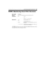
ECHP: Monitoring Host Print Sessions . . . . . . . . . . . . . . . . . . . . 92
ECNCBLOG: Taking NCB Traces . . . . . . . . . . . . . . . . . . . . . . . 93
ECSERVER: LAN Transport . . . . . . . . . . . . . . . . . . . . . . . . . . . . 94
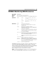
ECSNA: Monitoring SNA Resources . . . . . . . . . . . . . . . . . . . . . 95
Using ECSNA . . . . . . . . . . . . . . . . . . . . . . . . . . . . . . . . . . . . . 96
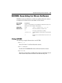
ECVER: Searching for Eicon Software . . . . . . . . . . . . . . . . . . . . 97
Using ECVER . . . . . . . . . . . . . . . . . . . . . . . . . . . . . . . . . . . . . 97
Chapter Seven
ECMODULE Command . . . . . . . . . . . . . . . 98
About ECMODULE . . . . . . . . . . . . . . . . . . . . . . . . . . . . . . . . . . . 99
ECMODULE: Monitoring the Eiconcard . . . . . . . . . . . . . . . . . . 101
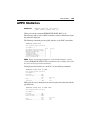
APPC Status . . . . . . . . . . . . . . . . . . . . . . . . . . . . . . . . . . . . . . . . 104
APPC Statistics . . . . . . . . . . . . . . . . . . . . . . . . . . . . . . . . . . . . . . 109
DIALER Status . . . . . . . . . . . . . . . . . . . . . . . . . . . . . . . . . . . . . . 112
Eicon IDLC Status . . . . . . . . . . . . . . . . . . . . . . . . . . . . . . . . . . . 123
Eicon IDLC Statistics . . . . . . . . . . . . . . . . . . . . . . . . . . . . . . . . . 125
Frame Relay Status . . . . . . . . . . . . . . . . . . . . . . . . . . . . . . . . . . . 127
Frame Relay Statistics . . . . . . . . . . . . . . . . . . . . . . . . . . . . . . . . 131
HDLC Status . . . . . . . . . . . . . . . . . . . . . . . . . . . . . . . . . . . . . . . . 133
HDLC Statistics . . . . . . . . . . . . . . . . . . . . . . . . . . . . . . . . . . . . . 137
SDLC Status . . . . . . . . . . . . . . . . . . . . . . . . . . . . . . . . . . . . . . . . 139
SDLC Statistics . . . . . . . . . . . . . . . . . . . . . . . . . . . . . . . . . . . . . . 142
SNA Status . . . . . . . . . . . . . . . . . . . . . . . . . . . . . . . . . . . . . . . . . 144
SNA Statistics . . . . . . . . . . . . . . . . . . . . . . . . . . . . . . . . . . . . . . . 149
SNA Function Management Status . . . . . . . . . . . . . . . . . . . . . . 150
SNA Function Management Statistics . . . . . . . . . . . . . . . . . . . . 153
SNA over Frame Relay Status . . . . . . . . . . . . . . . . . . . . . . . . . . 155
SNA over Frame Relay Statistics . . . . . . . . . . . . . . . . . . . . . . . . 159
7
X.25 Status . . . . . . . . . . . . . . . . . . . . . . . . . . . . . . . . . . . . . . . . . 161
X.25 Statistics . . . . . . . . . . . . . . . . . . . . . . . . . . . . . . . . . . . . . . . 167
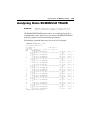
Analyzing Data: ECMODULE TRACE . . . . . . . . . . . . . . . . . . . 170
Trace Buffer . . . . . . . . . . . . . . . . . . . . . . . . . . . . . . . . . . . . . . 171
Trace Filter . . . . . . . . . . . . . . . . . . . . . . . . . . . . . . . . . . . . . . . 172
Sample ECMODULE TRACE Commands . . . . . . . . . . . . . . 174
Appendix A
Configuration Checklists . . . . . . . . . . . . 175
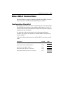
X.25 Connections . . . . . . . . . . . . . . . . . . . . . . . . . . . . . . . . . . . . 176
Configuration Checklist . . . . . . . . . . . . . . . . . . . . . . . . . . . . . 176
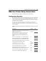
SNA Over Frame Relay Connections . . . . . . . . . . . . . . . . . . . . . 178
Configuration Checklist . . . . . . . . . . . . . . . . . . . . . . . . . . . . . 178
SNA Over Frame Relay Features. . . . . . . . . . . . . . . . . . . . . . 179
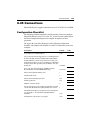
SDLC Connections . . . . . . . . . . . . . . . . . . . . . . . . . . . . . . . . . . . 180
Configuration Checklist . . . . . . . . . . . . . . . . . . . . . . . . . . . . . 180
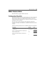
Eicon IDLC Connections . . . . . . . . . . . . . . . . . . . . . . . . . . . . . . 181
Configuration Checklist . . . . . . . . . . . . . . . . . . . . . . . . . . . . . 181
802.2 LLC Connections . . . . . . . . . . . . . . . . . . . . . . . . . . . . . . . 182
Configuration Checklist . . . . . . . . . . . . . . . . . . . . . . . . . . . . . 182
SNA Node Parameters . . . . . . . . . . . . . . . . . . . . . . . . . . . . . . . . 183
Appendix B
Performance Optimization . . . . . . . . . . . 184
Line Speeds and Performance . . . . . . . . . . . . . . . . . . . . . . . . . . 185
Propagation Delay . . . . . . . . . . . . . . . . . . . . . . . . . . . . . . . . . 185
Novell NetWare Networks . . . . . . . . . . . . . . . . . . . . . . . . . . . 185
X.25 Window Size . . . . . . . . . . . . . . . . . . . . . . . . . . . . . . . . . 186
HDLC Window Size . . . . . . . . . . . . . . . . . . . . . . . . . . . . . . . 187
Buffer and Packet Size . . . . . . . . . . . . . . . . . . . . . . . . . . . . . . 187
Eliminating Retransmission . . . . . . . . . . . . . . . . . . . . . . . . . . 188
8
Appendix C
User Facilities and
DTE Address Structure . . . . . . . . . . . . . . 190
User Facility Support . . . . . . . . . . . . . . . . . . . . . . . . . . . . . . . . . 191
Facility Types . . . . . . . . . . . . . . . . . . . . . . . . . . . . . . . . . . . . . 191
Facility Syntax . . . . . . . . . . . . . . . . . . . . . . . . . . . . . . . . . . . . 191
User Facility Request Codes . . . . . . . . . . . . . . . . . . . . . . . . . 192
Examples of User Facilities . . . . . . . . . . . . . . . . . . . . . . . . . . 193
Further Information on User Facilities. . . . . . . . . . . . . . . . . . 193
DTE Address Structure . . . . . . . . . . . . . . . . . . . . . . . . . . . . . . . . 194
DNIC . . . . . . . . . . . . . . . . . . . . . . . . . . . . . . . . . . . . . . . . . . . 194
National Number . . . . . . . . . . . . . . . . . . . . . . . . . . . . . . . . . . 194
Examples of DTE Addresses . . . . . . . . . . . . . . . . . . . . . . . . . 195
Networks and DNICs . . . . . . . . . . . . . . . . . . . . . . . . . . . . . . . 196
X.25 Cause and Diagnostic Codes . . . . . . . . . . . . . . . . . . . . . . . 199
Cause Codes . . . . . . . . . . . . . . . . . . . . . . . . . . . . . . . . . . . . . 201
ISDN Cause and Diagnostic Codes . . . . . . . . . . . . . . . . . . . . . . 202
NI-1 (North America). . . . . . . . . . . . . . . . . . . . . . . . . . . . . . . 202
TPH1962 (Australia) . . . . . . . . . . . . . . . . . . . . . . . . . . . . . . . 205
EuroISDN (Europe) and INS-Net 64 (Japan) . . . . . . . . . . . . 206
AT&T 5ESS (North America) . . . . . . . . . . . . . . . . . . . . . . . . 209
ASCII Control Codes . . . . . . . . . . . . . . . . . . . . . . . . . . . . . . . . . 211
Index . . . . . . . . . . . . . . . . . . . . . . . . . . . . 213
Introduction
Before You Begin
T
HIS SECTION PROVIDES AN OVERVIEW OF THE DOCUMENTATION SET
provided with Eicon SNA Gateway. This guide provides complete
instructions on how to configure and start Eicon SNA Gateway and
associated resources.
To help you access information more easily, read this section for a brief
description of the reference material provided with your Eicon SNA
Gateway package.
Eicon SNA Gateway Documentation
10
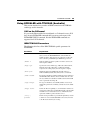
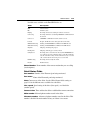
Eicon SNA Gateway Documentation
The complete Eicon SNA Gateway documentation set consists of the following
items:
Documentation
Contains
Release Notes
Up-to-date features and changes to this product.
Installation Guide
Complete installation procedures.
Operator’s Guide
Description of configuration options.
Various gateway configuration scenarios.
Description of the Eicon Management Tool.
Command line syntax for operating your Eicon SNA
Gateway.
Eicon Configuration Program
Online Help
Screen-sensitive help for all configuration screens.
Syntax Conventions
11
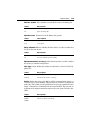
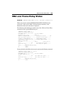
Syntax Conventions
The commands in this book use the following syntax:
Syntax Example
Description
RESET
Items in capital type are keywords. They can be entered in
either uppercase or lowercase.
[/C n]
Items enclosed by a pair of square brackets are considered
optional. You can either include them or not. Do not enter
the brackets.
n
Items in lowercase italic type are user supplied input.
Replace these items with the values you need, a number or
a string of characters.
THIS | THAT
Two items separated by a vertical bar means choose one
item. Do not enter the vertical bar.
node1 ... noden
Items separated by an ellipsis indicate that you can enter a
list of values.
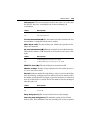
For example, if a command is presented as:
RESET [ cfgfile ] [ node1 ... noden ] THIS | THAT
Then, you know that:
RESET
Enter as shown.
cfgfile
Use or omit this parameter, as you choose. If you use it, you
must replace cfgfile with a value you supply.
node1 ... noden
You may provide a list of values, for example SANJOSE,
SANFRAN, OAKLND and so on.
THIS | THAT
You must enter a value for either of the specified parameter.
Chapter Summary
12
Chapter Summary
The following is a summary of each of the chapters in this book.
Chapter One, “Introduction”: Introduces Eicon SNA Gateway.
Chapter Two, “Configuring Eicon SNA Gateway”: Describes how to use the
Eicon Configuration Program to configure Eicon SNA Gateway.
Chapter Three, “SNA Resource Manager”: Describes how to configure the
SNA Resource Manager module of the Eicon SNA Gateway.
Chapter Four, “Host Print”: Describes how to configure the Host Print module
of Eicon SNA Gateway.
Chapter Five, “Remote Operation”: Describes how to operate the gateway
from a remote client workstation.
Chapter Six, “Eiconcard Commands”: Describes the Eiconcard command line
utilities, their syntax and use.
Chapter Seven, “ECMODULE Command”: Describes the use and syntax of
the ECMODULE command.
Appendix A, “Configuration Checklists”: Provides additional information on
configuration of Eicon SNA Gateway.
Appendix B, “Performance Optimization”: Provides performance statistics for
all Eiconcards, and offers guidelines for optimizing performance.
Appendix C, “User Facilities and DTE Address Structure”: Describes X.25
network user facilities, and the DTE address structure.
Chapter One
Introduction
T
HIS CHAPTER IS AN INTRODUCTION TO, AND AN OVERVIEW OF,
Eicon SNA Gateway and its functionality.
About Eicon SNA Gateway
14
About Eicon SNA Gateway
Eicon SNA Gateway is designed to work under Microsoft® Windows® 2000
(Professional, Server, Advanced Server, or Datacenter Server). The gateway
uses SNA protocols to connect client workstations in remote branch offices to
corporate IBM® hosts.
Eicon SNA Gateway supports the use of 802.2 LLC, Frame Relay, SDLC, X.25
and Eicon IDLC WAN protocols over leased, dialup, and ISDN lines. It also
works in conjunction with Eicon Networks’ Eiconcard LAN Client, the full
range of Eicon application development toolkits, and the Access® and Aviva®
families of terminal emulations software to provide client workstations access
to remote host applications.
Eicon SNA Gateway Architecture
There are two versions of the Eicon SNA Gateway: SNA LAN Gateway and
SNA Connect. For the purposes of this guide, “Eicon SNA Gateway” is used
to refer to either of these products, and the phrase “gateway PC” is used to refer
to the computer on which the Eicon SNA Gateway software is installed.
SNA LAN Gateway
SNA LAN Gateway provides client workstations on a LAN with access to
remote hosts. This product has a LAN-based architecture that follows a client/
server paradigm. The SNA LAN Gateway software is installed on a LAN PC,
which becomes the gateway PC (server) that provides access to connected host
computers. The gateway PC, in turn, is accessed by client workstations on the
LAN that are equipped with terminal emulation or other connectivity software
such as the Eiconcard LAN Client software. Client workstations on the LAN
can use the TCP/IP and IPX/SPX LAN protocols to connect to the SNA LAN
Gateway.
SNA Connect
SNA Connect is a PC-based remote access package. SNA Connect does not
have the same LAN-based architecture of the SNA LAN Gateway. Instead it
is designed to enable standalone workstations in branch offices to connect to
remote hosts.
1 The Eicon Access and Aviva terminal emulation software products are available from Aviva
Solutions Inc. For more information, go to www.avivasolutions.com.
Eicon SNA Gateway Components
15
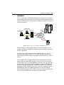
Eicon SNA Gateway Components
Eicon SNA Gateway is a combination of sophisticated communications
hardware and software. The Eicon SNA Gateway software consists of SNA
protocol software and, for the SNA LAN Gateway, LAN Transport services.
The diagram below presents an overview of Eicon SNA Gateway components
and installation locations:
Eicon SNA Gateway
Software
Eiconcard
(SNA LAN Gateway only)
(SNA LAN Gateway only)
Eicon SNA Gateway components
The gateway PC maintains the link to remote host computers and handles all
processing of 802.2 LLC, SDLC, X.25/QLLC, Frame Relay, or Eicon IDLC
communications protocols. Most of the work is actually done by the Eiconcard,
allowing the gateway PC to be used for other tasks as well.
SNA LAN Gateway includes LAN Transport software that enables the gateway
PC to provide communications services to workstations on the LAN.
Workstation users run terminal emulation software, such as Aviva® for
Desktops, to establish connections with any host to which the gateway PC is
linked.
Eiconcard Support
16
Eiconcard Support
The Eiconcard is the hardware device used to operate the Eicon SNA Gateway.
It is an intelligent communications coprocessor, with its own CPU and onboard memory. It is sold separately.
Depending on which Eiconcard you have, the external interface support
includes V.24 (RS-232 and X.21bis), V.35, X.21 with V.11 (X.27), and ISDN
Basic Rate Interface (BRI).
The type of Eiconcard (adapter) you choose depends on the volume of
information you need to transmit and the number of connection types you will
use. Eicon SNA Gateway supports the use of multiple Eiconcards under
Windows 2000.
The following is a list of Eiconcards that are supported by Eicon SNA Gateway:
Card
Type
Serial Interface
Eiconcard C20
C-Series
1 V.24
Eiconcard C21
C-Series
1 V.24, 1 ISDN BRI
Eiconcard C90
C-Series
1 V.24
Eiconcard C91
C-Series
1 V.24, 1 ISDN BRI
Eiconcard S50
S-Series
1 HSI
Eiconcard S51
S-Series
1 HSI, 1 ISDN BRI
Eiconcard S52
S-Series
2 HSI
Eiconcard S90
S-Series
1 VHSI
Eiconcard S91
S-Series
1 VHSI, 1 ISDN BRI
Eiconcard S92
S-Series
2 VHSI
Eiconcard S94
S-Series
2 VHSI
SNA Protocol Support
17
SNA Protocol Support
This section describes briefly the different protocols that you can use with
Eicon SNA Gateway to link to a remote host.
Integrating with IBM’s SNA
IBM’s SNA (System Network Architecture) is a seven-layered architecture that
controls the exchange of information between IBM systems. Eicon SNA
Gateway provides full support for SNA protocols including: SNA Path Control,
SNA Function Management, APPC/LU6.2, and NetView over data-link
protocols such as 802.2 LLC, SDLC, X.25/QLLC, Frame Relay, and Eicon
IDLC. These protocols are fully configurable to meet the needs of specific
implementations.
Nodes and Logical Units
In IBM’s SNA architecture, the access point for the SNA network is the logical
unit (LU). One or more LUs are managed by a Node, which is typically a
dedicated piece of equipment called the cluster controller. The gateway
protocol software emulates multiple cluster controllers on the Eiconcard,
requiring minimal overhead on the gateway PC. Eiconcards can emulate up to
32 nodes, with up to 254 fully configurable LU definitions.
SNA Connectivity
Eicon SNA Gateway provides access to a variety of IBM hosts over 802.2 LLC,
SDLC, Eicon IDLC, X.25/QLLC, and Frame Relay links. These protocols are
also supported over ISDN. With Eicon SNA Gateway you can connect to S/370,
S/390, and ES9000 mainframes, as well as AS/400, System/36, and
System/38 midrange systems.
Client workstations can use desktop terminal emulation products, such as
Aviva for Desktops, and a full range of Eicon Networks’ application
development toolkits for advanced program-to-program connectivity (APPC)
or for access to SNA host applications (SNAFM).
SNA Protocol Support
18
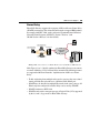
SDLC
SDLC (Synchronous Data Link Control) is the primary data link protocol used
for wide-area network connections within SNA. It is used to manage
information exchanged across a single physical data link between two nodes.
01
IB
M
Client Workstation
App
(SNA LAN Gateway only)
Gateway PC
Client Workstation
(SNA LAN Gateway only)
Syst 9404
licat em/4
ion
00
SDLC Point-to-Point
or Multipoint
AS/400
Dial-up SDLC
Client Workstation
(SNA LAN Gateway only)
3745 IBM Mainframe
Making SDLC connections with Eicon SNA Gateway
SDLC is part of the original design of SNA, and is the foundation upon which
all other connections are based. The Eiconcard supports point-to-point,
multipoint, and switched dial-up SDLC links.
SNA Protocol Support
19
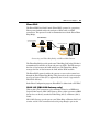
X.25/QLLC
X.25 is a widely supported internetworking protocol used by private and public
telecommunications networks. X.25 is designed to carry high volumes of data
quickly and without errors, and uses packet-switching to transmit data between
connected computers.
Client Workstation
(SNA LAN Gateway only)
Gateway PC
Client Workstation
(SNA LAN Gateway only)
X.25 Link
(QLLC)
Client Workstation
(SNA LAN Gateway only)
X.25 Link
(QLLC)
IBM Mainframe
3745 (NPSI)
X.25
Packet-Switched
Network
X.25 Link
(QLLC)
01
IB
M
Application
System/40
0
IBM AS/400
Making an X.25 connection using Eicon SNA Gateway
Eicon Networks’ products comply with X.25 network standards in over 45
countries and adhere to GOSIP (Government Open Systems Interconnection
Profile) requirements.
For SNA (System Network Architecture) communications over an X.25
connection, Eicon SNA Gateway uses the QLLC (Qualified Logical Link
Control) protocol. QLLC is SNA data packaged for transmission over an X.25
network.
An X.25/QLLC line can support multiple logical connections over a single
physical link. Once Eicon SNA Gateway is connected to the X.25 network, it
can then link to any X.25-attached IBM host. You must, however, make sure
that Network Packet Switching Interface (NPSI) is running on the front-end
processor (FEP) of the host. NPSI is an IBM program that allows IBM host
applications running VTAM to communicate over X.25-compliant networks.
This IBM program runs in an IBM communications controller with the
Network Control Program (NCP). NPSI is required to implement QLLC and
allow 3725 or 3745 FEPs to be accessible via an X.25 network.
SNA Protocol Support
20
Frame Relay
Eicon SNA Gateway supports the transport of SNA traffic over Frame Relay
(SNA/FR) connections. This allows Eicon Networks to support IBM products
that comply with RFC 1490, such as Advanced Communications Function/
Network Control Program (ACF/NCP) Version 7 Release 1 and
OS/400 Version 2 Release 3 for the AS/400.
01
IBMAppliSyste
cationm/40
0
Client Workstation
IBM AS/400
(SNA LAN Gateway only)
Gateway PC
Client Workstation
(SNA LAN Gateway only)
Frame Relay
Network
Client Workstation
(SNA LAN Gateway only)
3745
IBM Mainframe
Making SNA connections over a Frame Relay network with Eicon SNA Gateway
Node Types 2.0 or 2.1 locally emulated on Eicon SNA Gateway can connect
to remote AS/400s or 3745s via Frame Relay networks.The following features
are supported with Eicon Networks’ implementation of SNA over Frame
Relay:
• Traffic originating from multiple nodes may be sent over the same virtual
circuit provided that each node uses a different SSAP-DSAP pair.
• SNA/FR may be installed on multiple Eiconcards in the same gateway. All
Eiconcard ports configured for Frame Relay can be used by SNA/FR.
• SNA/FR conforms to RFC 1490.
• SNA/FR can be used to transport any type of Logical Units (LUs) supported
by the 2.0 and 2.1 type nodes in Eicon SNA Gateway.
SNA Protocol Support
21
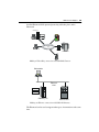
Eicon IDLC
The Eicon ISDN Data Link Control (Eicon IDLC) protocol is a proprietary
Eicon protocol which enables the transport of SNA traffic via ISDN
connections. This protocol is used in communications with the Eicon Token
Ring Bridge.
Client Workstation
(SNA LAN Gateway only)
Gateway PC
Client Workstation
(SNA LAN Gateway only)
Token Ring Bridge PC
Eicon IDLC
Link
Client Workstation
(SNA LAN Gateway only)
Token Ring
LAN
Front-End
Processor
IBM Mainframe
Connecting to a Token Ring Bridge with Eicon SNA Gateway
The Token Ring Bridge resides on the same Token Ring LAN as the SNA host’s
communications controller or Front-end processor (FEP). The FEP manages
the flow of data between the LAN and the host. The Token Ring Bridge
manages the flow of data between the LAN and the ISDN network.
The Eicon IDLC protocol enables the gateway to access to the remote host
through the Eicon Token Ring Bridge. This protocol can be used to transport
any type of Logical Units (LUs) supported by the 2.0 and 2.1 type nodes in
Eicon SNA Gateway.
In the Eicon Configuration program, Eicon IDLC is abbreviated as EC-IDLC.
802.2 LLC (SNA LAN Gateway only)
With an 802.2 LLC connection (also commonly referred to as IEEE 802.2
Logical Link Control), SNA LAN Gateway allows a client to connect to IBM
devices that are directly attached to Token-Ring (802.5) or Ethernet (802.3)
LANs.
SNA LAN Gateway uses the port on your Token-Ring or Ethernet LAN card
to make an 802.2 LLC connection instead of going through a port on the
SNA Protocol Support
22
installed Eiconcard. SNA protocol processing still takes place on the
Eiconcard.
$%%#
(" )
)% %
" " ! *
#
! ! " !"#
# # $% " &
' "# " ! + )
0
,%
)
Making a Token-Ring connection with SNA LAN Gateway
6\
SO LFD
$S 0
,%
P
VWH WL RQ
Making an Ethernet connection with SNA LAN Gateway
The Eiconcard can be used to support other types of connections at the same
time.
23
SNA Protocol Support
Data travels from a workstation PC along the backbone to the SNA Gateway.
It is packaged into SNA frames and returned to the LAN so it can be collected
by an IBM controller or host.
Information returning from the host travels along the LAN to the Eiconcard in
the SNA Gateway where it is unpackaged and then sent to its destination PC
across the LAN.
ISDN Support
ISDN (Integrated Services Digital Network) provides end-to-end digital
connectivity to support a wide range of services.
QLLC/ISDN
Links
Client Workstation
01
(SNA LAN Gateway only)
IBMAppl Syst
icatioem/4
n 00
Gateway PC
Client Workstation
(SNA LAN Gateway only)
IBM AS/400
X.25
Network
Client Workstation
(SNA LAN Gateway only)
SDLC/ISDN
Link
Terminal
Adapter
3745
IBM Mainframe
Connecting to IBM hosts over ISDN lines with Eicon SNA Gateway
Since ISDN standards vary from country to country, Eiconcard software has
been developed to suit the different implementations. Currently, Eicon
Networks supports the following ISDN implementations: NI-1 (North
America), INS-Net64 (Japan), TPH 1962 (Australia), EuroISDN (Europe), and
5ESS (AT&T proprietary).
ISDN support is provided through the C21, C91, S51, and S91 Eiconcards as
well as Eicon SNA Gateway software. The X.25/QLLC, SDLC, Eicon IDLC
and SNA over Frame Relay protocols are supported over ISDN.
The C21, C91, S51, and S91 Eiconcards support ISDN Basic Rate Interface
(BRI) connections. BRI is defined as two 64kbps B Channels and one 16 kbps
D Channel. The B Channels are protocol independent and can carry X.25,
SNA Protocol Support
24
SDLC, and SNA over Frame Relay traffic. The D Channel is a signaling
channel that controls B Channel usage. Some national implementations such
as NI-1 can carry X.25 data as well as signaling on the D Channel.
Chapter Two
Configuring Eicon SNA Gateway
T
HIS CHAPTER DESCRIBES HOW TO CONFIGURE THE EICON SNA
GATEWAY using the Eicon Configuration Program.
Overview
26
Overview
Eicon SNA Gateway configuration is a two-part process.
1
2
Configure the Eiconcard(s) and LAN Transport.
Configure the applications that will use the Eiconcards and Eicon SNA
Gateway software (for example, Host Print).
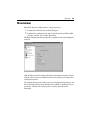
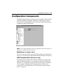
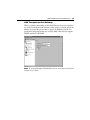
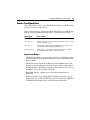
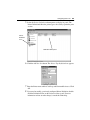
The Eicon Configuration Program provides a graphical view of all configurable
resources.
Click the Eiconcard icon to display the Eiconcard configuration panel. Doubleclick the same icon to reveal additional icons used to activate port and protocol
configuration options.
The configuration program enables you to set all configuration parameters and
the relationships between them. Default values, which are provided for most
parameters, facilitate the selection process and may generally be left
unchanged.
Configuration Components
27
Configuration Components
The Eicon Configuration Program consists of several modules. These modules
include the following components: EiconServer, LAN Transport, Service
Trace, 802.2 LLC (SNA LAN Gateway), Eiconcard, SNA Resource Manager,
and Host Print (SNA LAN Gateway).
Note Use the Online Help for the Eicon Configuration Program to guide you
through the configuration of the gateway.
EiconServer (computer name)
The server icon represents the gateway PC. The computer name, EiconServer
in this case, can be changed only through the Windows 2000 System Properties.
LAN Transport (SNA LAN Gateway only)
The LAN Transport module handles Eiconcard LAN Server configuration.
Although Eiconcard LAN Server is configured in the Eicon Configuration
Program, it is an independent component and does not require any optional
services support. Configuring this component allows for client-server
connectivity. For more information see “LAN Transport (Eiconcard LAN
Server)” on page 38.
Configuration Components
28
Service Trace
The Service Trace component is a diagnostic tool. It enables you to configure
traces for the LAN Transport and for 802.2 LLC connections.
802.2 LLC (SNA LAN Gateway only)
Although this component is visible in the navigator window, there are no
configurable options. Its sole purpose is to indicate whether or not support for
802.2 LLC connections has been enabled.
Eiconcard
The Eiconcard handles all link-level and high-level protocol processing for
each type of connection. You must configure a separate Eiconcard port for each
individual physical connection (SDLC, X.25, Frame Relay, or Eicon IDLC)
you want to make.
However, in the case of 802.2 LLC connections, communication takes place
through the LAN card and it is not necessary to configure an Eiconcard port.
SNA Resource Manager
The SNA resource manager controls the definition and allocation of all SNA
resources, which include nodes and LUs.
Configuration of the SNA Resource Manager component is discussed in
Chapter Three, “SNA Resource Manager.”
Host Print (SNA LAN Gateway only)
Host Print provides print queue services to client workstations on the SNA
LAN Gateway. It allows client print jobs to be directed to any shared print
queue on the network.
Configuration of the Host Print component is discussed in Chapter Four, “Host
Print.”
The Eicon Configuration Program
29
The Eicon Configuration Program
The Eicon Configuration Program is designed to assist you in the configuration
of Eicon SNA Gateway resources. Its graphical user interface provides a view
of the logical structure of the gateway configuration components, displaying
all installed hardware and software.
The Navigator is composed of a series of icons that show the current logical
configuration path. When you click an icon, the parameters associated with the
corresponding component appear in the parameter area.
Adding and Deleting Configuration Components
Once you have finished setting the parameter values for a particular
configuration component on the Navigator, you may click the
button or
button to cancel
another item in the Navigator to accept them, or click the
your entries.
Each time a change or addition is made, the Navigator reflects the
modifications to the logical configuration path. With this mechanism, you can
select any component directly, and then modify the desired parameters in the
parameter area. In addition, the Eicon Configuration Program scans the
Navigator to detect which components, if any, are affected by a change. See
the “Scanning Dependent Configuration Items” topic provided by the online
help for the Eicon Configuration Program.
Once you leave a configuration panel and select another item in the Navigator,
all newly configured parameters are automatically stored in memory. To
permanently save them, click the
button or choose the File Save option.
Altering Protocol Parameters
When a parameter is changed, all parameters affected by the change in the
current configuration panel are updated. In addition, if these changes affect
parameters in other Eicon SNA Gateway components, a warning message
appears that displays the names of the affected parameters.
If any of the settings on the current panel are not valid, the Eicon Configuration
Program will not allow you to proceed to the next parameter or configuration
panel. Also, all required parameters must be configured for proper
functionality.
The Eicon Configuration Program
30
Each protocol has a number of parameters associated with it. These parameters
let you customize the protocol software for your particular connection.
However, in most cases you will not have to change the default values of these
parameters.
Eicon SNA Gateway protocols can be configured to suit almost any
communications situation. However, since there are so many types of
equipment, switches, and networks with which the gateway can interact, there
can be uncertainty about which parameters need to be changed. To simplify
the configuration process, the best possible default values have already been
determined for each protocol parameter, and in most cases the parameters do
not need to be changed.
In some cases, you will have to change the default values of certain parameters.
Refer to the section “Configuration Notes” on page 40 of this chapter for more
information.
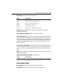
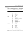
Eicon Configuration Program Menus
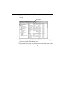
The following table describes all the available menu options.
File Menu
Option
Description
Save...
Saves the gateway configuration settings to the Windows registry.
Import...
Allows you to load an existing gateway configuration file into the Eicon
Configuration Program.
Export...
Allows you to save the configuration settings, including Eiconcard
number and type, to an ASCII file. The default file extension is .EIC.
Select Computer
Allows you to identify the remote server name for remote configuration.
Exit
Closes all Eicon SNA Gateway windows and exits the
Eicon Configuration Program.
Note Do not import a configuration file if the type of card in the gateway PC
has been changed, or if the number of cards in the gateway PC has been
changed.
Use File Import to apply different connections, Host Print, or SNA Resource
Manager configurations to the same card(s).
The Eicon Configuration Program
31
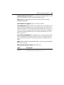
Parameters Menu
Option
Description
Undo
Cancels all changes made to the current configuration panel.
Confirm entries
Saves all changes made to the configuration panel currently displayed.
Properties
Invokes the configuration panel for certain configurable parameters.
Help Menu
Option
Description
Contents
Contains general help topics for the Eicon Configuration Program.
About
Copyright and version information for the Eicon Configuration
Program.
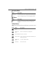
Toolbar Buttons
Click an Eicon Configuration Program toolbar button to perform the desired
action:
Button
Name
Description
Save configuration Saves your current configuration.
button
Add new item
button
Inserts a new element into your configuration.
Delete item button Deletes the selected item.
Properties button
Displays configuration panels for this item and allows you to
edit the entry as desired.
Confirm entries
button
Accepts the configured settings.
Undo button
Undoes the last action.
The Eicon Configuration Program
32
Online Help
Included with the Eicon Configuration Program is extensive and contextsensitive online help for each configuration parameter. Just click on the
parameter in which you are interested and press “F1.”
Note You may want to have the Online Help window open while you configure
your Eicon SNA Gateway components. To do this, open the Help Window, click
the Options button, and choose Keep Help on Top. You can then position the
online help window beside the configuration panel for easy reference during
configuration.
The Online Help for the Eicon Configuration Program provides information
to help you configure Eicon SNA Gateway. The following topics are covered
online:
• About the Eicon Configuration Program
• The Navigator: An Overview — displays a graphical representation of each
Eicon SNA Gateway component and subcomponent as well as a brief
description
• Using the Navigator — describes how to move around the Navigator and
access information quickly and easily
• Creating a New Configuration File — describes how to change your
configuration then save it in a file for future use
• Commands and Buttons — complete descriptions of all toolbar buttons and
menu options
• Getting Help — describes how to use the online help for the Eicon
Configuration Program
• Glossary of networking terms (click the Glossary button)
• Alphabetical index of all program parameters showing the valid ranges and
default values
Eiconcard Configuration
33
Eiconcard Configuration
The Eiconcard component displays the currently configured parameters for the
specified Eiconcard.
Each Eiconcard component contains a number of different configuration panels
that allow you to adjust parameters in the following areas:
• Eiconcard
• High-Level Protocols
• Ports
High-Level Protocol Configuration
Eicon SNA Gateway supports the following high-level protocols:
• APPC/LU 6.2
• SNA Function Management
• SNA Path Control
• NetView Support
• Message Protocol
Eiconcard Configuration
34
The protocols APPC/LU 6.2, SNA Function Management, and SNA Path
Control provide support for SNA communications at different levels. SNA Path
Control provides the lowest level of support and APPC/LU 6.2 provides the
highest. For the higher level protocols to operate, the lower level protocols must
be activated.
Select the High-Level Protocols icon to display the configuration panel.
APPC/LU 6.2
Advanced Program-to-Program Communication (APPC) is used by a wide
variety of transaction programs for program-to-program communications.
Eicon SNA Gateway provides complete support for LU 6.2. If your application
requires peer-to-peer connections, or if you are using the Eicon Networks
APPC Toolkit, you should activate this protocol. If you select this option, the
configuration program automatically selects the other protocols required to
operate APPC/LU 6.2; SNA Function Management and SNA Path Control.
SNA Function Management
SNA Function Management starts automatically when APPC is activated.
Many third-party terminal emulators interface with Eicon SNA Gateway at this
level. SNA Function Management also needs to be active if you define nodes
with support for LU 0, or if you use Eicon Networks SNA Function
Management Toolkit applications.
Eiconcard Configuration
35
SNA Path Control
SNA Path Control starts automatically when SNA Function Management is
activated. SNA Path Control must be active if you intend to support SNA nodes.
All Aviva 5250 and 3270 terminal emulations interface with Eicon SNA
Gateway at this level.
NetView Support
Activating NetView support lets your Eicon SNA Gateway become a part of
an IBM NetView or System Center Net/Master network management system.
Information about the gateway and its status is reported to the host through
Entry Point functions. Commands from a NetView host terminal are executed
on the gateway via the Service Point functions using RUNCMD.
Integration with IBM’s NetView and System Center Net/Master provides the
capability to control and view the gateway from a remote console. Activate
Eicon Networks’ NetView Support to provide the following features:
• NetView Entry Point implementation forwards SNA alerts, data-link
statistics and Response Time Monitor (RTM) data to NetView.
• NetView Console provides local display of Response Time Monitor (RTM)
and statistical data, and operator generated alerts.
• NetView Service Point RUNCMD Agent supports remote execution of
Eicon SNA Gateway commands from NetView’s Network Control
Command Facility.
Message Protocol
This protocol is proprietary to Eicon Networks. Select this protocol if you need
to do either of the following:
• Use Aviva’s Desktop X.25 connections type to connect to the remote host
over X.25 connections.
• Make an 802.2 LLC connection to the remote host.
Eiconcard Configuration
36
Port Configuration
Use the Port configuration panel to assign the line protocols and dialer options
for each port.
Line Protocol Configuration
Line protocols handle the data transfer. The configuration program supports
the line protocols listed below through the physical ports of the Eiconcard.
• Eicon IDLC
• Frame Relay
• SDLC
• X.25
For further information on these protocols see “SNA Protocol Support” on
page 17.
Note The 802.2 LLC protocol does not require the use of an Eiconcard port.
Eiconcard Configuration
37
Dialer Configuration
Eicon SNA Gateway supports a number of options for dialing both internal
and external modems. Select one of these options based on the Eiconcard and
line type you are using:
• Direct (hardware dialer)
• Hayes AT (asynchronous dialer)
• V.25bis
• BChannel (ISDN)
• SIG.+X.25 (ISDN)
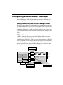
LAN Transport (Eiconcard LAN Server)
38
LAN Transport (Eiconcard LAN Server)
There are two components to the Eiconcard LAN software: a server component
(installed on the gateway PC) and a client component (installed on each client
workstation). Together these two components handle connections between the
gateway PC and all client workstations on the LAN or other connected LANs.
Eiconcard LAN is currently supported over TCP/IP and IPX/SPX.
For DOS, Windows and OS/2 clients, the Eiconcard LAN software allows
clients to use the services of a backup gateway PC if the primary gateway PC
becomes unavailable. It also provides the ability to activate, deactivate, and
monitor sessions on the gateway PC from the client workstation.
DOS, Windows, or OS/2
ECLAN Client Workstation
TCP/IP or IPX/SPX LAN
Primary
Gateway PC
with
ECLAN Server
Secondary
Gateway PC
with
ECLAN Server
X.25, SDLC, Frame Relay,
or Eicon IDLC connections
Remote Host
Client connections to remote hosts via SNA LAN Gateway
LAN Transport (Eiconcard LAN Server)
39
LAN Transport on the Gateway
There is no limit to the number of SNA LAN Gateways that can be installed
on a LAN. To configure LAN Transport on the gateway, you must specify the
number of sessions the gateway has to support. In addition you must also
specify the LAN protocols that you are using. SNA LAN Gateway supports
TCP/IP and Novell’s IPX/SPX.
Note If you install multiple SNA LAN Gateways on your LAN, each must have
a unique Server Name.
Configuration Notes
40
Configuration Notes
The following are important considerations when you configure certain Eicon
SNA Gateway parameters.
Configuration Values
When you subscribe to an X.25 or Frame Relay network, your network services
provider should supply you with documentation on the characteristics of that
network. If documentation has not been provided, contact the agency that
installed the connection and request this information.
Review each parameter of the X.25 or Frame Relay network, and make sure
that your Eicon SNA Gateway configuration parameter values match the
corresponding X.25 or Frame Relay network parameter values. For example,
if the X.25 network has a default packet size of 256, and the Eicon SNA
Gateway configuration parameter is set to a default packet size of 128, then
you may encounter problems transmitting data over the X.25 network.
X.25 PVCs
If you configure only X.25 permanent virtual circuits (PVCs) in the X.25
configuration panel, make sure to configure a port for “X.25 PVC.” By default,
“X.25 SVC” is set, and will prevent any sessions from being established if you
do not change this value.
Dialer Sync Configuration
• If you configure your Eiconcard with the Clocking parameter set to
“INT+DPLL” and the Data Encoding parameter set to “NRZI,” the
maximum value of the Line Speed parameter is 19200 bps.
• If you configure your Eiconcard with the Clocking parameter set to
“INT+DPLL” and the Data Encoding parameter set to “FM0” or “FM1”,
the maximum value of the Line Speed parameter is 38400 bps.
• If you configure your Eiconcard with the Clocking parameter set to “INT,”
you must make sure that the cable(s) are properly attached and terminated
on the other end. Failure to do so may result in an Out of State condition for
the Eiconcard. It may also cause the Eiconcard commands (ECCARD,
ECMODULE, and ECDIALER) to function improperly.
Configuration Notes
41
SDLC Window Size and Frame Size
To connect to a host using SDLC, you must make sure that parameters such as
your window and frame size match those of the host. For example, the Eicon
SNA Gateway configuration frame size is set to a default of 267 octets. If the
host’s frame size is different from this value, you will encounter problems
transmitting data. If you do not know the host’s parameter values, contact the
host’s system operator.
Frame Relay DLCI
When you subscribed to a Frame Relay network, you should have received
documentation from your network services provider about network
characteristics such as your DLCI(s) and the N1 through N3 parameters. You
should ensure the best possible match between the Eicon SNA Gateway
Configuration values for Frame Relay and those used by your Frame Relay
network.
Note Do not use Dynamic DLCI with SNA over Frame Relay connections.
Stopping and Restarting the Eiconcard and Related Services
42
Stopping and Restarting the Eiconcard
and Related Services
Each time you reconfigure any Eiconcard component, you must stop and then
restart the Eiconcard(s) installed in the gateway PC, and any related services,
for the changes to take effect. Use Windows 2000 Computer Management to
stop and restart the Eiconcard(s) and related services.
➤ To stop and restart the Eiconcard(s):
1
On the Desktop, right-click My Computer, and then click Manage. The
Computer Management dialog box opens.
2
In the left pane, click Services and Applications and then, in the right
pane, double-click Services.
Stopping and Restarting the Eiconcard and Related Services
3
43
Highlight the Eicon Cards entry in the Services list and click the stop
button.
Stop button
4
If they are started, stop the ECLAN and ECLLC services also. Highlight
the service and then click the stop button.
5
To restart the Eiconcard(s) and related services, select their entries in the
Services list and click the start button .
Chapter Three
SNA Resource Manager
T
HIS CHAPTER DESCRIBES THE SNA RESOURCE MANAGER COMPONENT
of the Eicon SNA Gateway, and how to configure it. The SNA Resource
Manager controls the definition and allocation of all SNA resources.
45
Configuring SNA Resource Manager
Configuring SNA Resource Manager
Eicon SNA Gateway’s SNA Resource Manager controls the definition and
allocation of all SNA resources. These resources include Nodes and LUs.
Adding and Deleting SNA Resource Manager Items
The SNA Resource Manager’s Nodes and LUs are manipulated from within
the information window. After you select a component in the Navigator, click
one of the items listed in the information window before you insert, delete, or
modify them. Each time you make any changes to these resources, they must
be stopped and restarted, with the ECSNA command, for the changes to take
effect.
IBM Architecture
In IBM’s architecture, the access point into the SNA network and to a host
computer is the Logical Unit (LU). One or more LUs are always managed by
a Node (Physical Unit or PU), which is generally implemented by a dedicated
piece of equipment called the cluster controller. The gateway protocol software
can emulate multiple cluster controllers on the same Eiconcard, requiring
minimal overhead on the gateway PC. Each Eiconcard can emulate up to 32
Nodes (PUs), with up to 254 fully configurable LU definitions.
3270 Node 1 (SDLC)
LU1
LU2
LU3
LU4
LU5
LU6
Node 1
APPC/LU 6.2
SDLC
Direct
Port 1
X.25/
QLLC
V.25bis
Port 2
Node 2
SNA Function Management
Node 3
SNA Path Control
Node 4
802.2 LLC
Node 6
Node 5
LAN Card
5250 Node 4 (X.25)
3270 Node 6 (802.2)
LU1
LU1
LU2
LU3
LU4
LU5
LU6
LU2
LU3
LU4
LU5
LU6
Configuring SNA Resource Manager
46
Node Configuration
Node configuration is where you define the characteristics of each SNA Node
you want to activate on the gateway.
There are four Node types supported by Eicon SNA Gateway. Each Node type
provides services required to manage and use a particular type of device.
Node Type
Description
Node Type 1.0
Defines support services for 5250 Display and Printer devices
Node Type 2.0
Defines support services for 3270 Display and Printer devices, LU 0,
and dependent LU 6.2 types.
Node Type 2.1
Defines support for independent APPC/LU 6.2 types (peer-to-peer)
and APPN Low Entry Networking (LEN Node).
Node Type 5494
Defines support for 5250 Display and Printer devices over SDLC,
X.25/QLLC, and 802.2 LLC communication links.
Important Notes
• When defining a Node, you must specify parameters to define the remote
peer Node addressing information, and reserve space on the Eiconcard for
Node resources.
• The Eiconcard can emulate up to thirty-two Nodes simultaneously. This
depends on available Eiconcard memory and the memory requirements of
the Node definition. Specifying a large Frame Size and many LUs increases
the amount of memory required by the Node.
• Eicon SNA Gateway supports up to 32 concurrent connections per
Eiconcard.
• When you define a Node with the Eicon Configuration Program, give it a
unique name. It is recommended that this name correspond to the IBM host
VTAM Node definition for easier overall network management.
Configuring SNA Resource Manager
47
Configuring Nodes
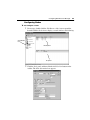
➤ To configure a node:
1
If necessary, double-click the SNA Resource Mgr icon to expand the
branch. Click the Nodes icon to display a screen similar to the following:
Click Nodes
icon
Node panel
LU panel
2
Click the Node panel and then click the Add New Item button on the
toolbar. The Node Information box appears.
Configuring SNA Resource Manager
3
48
Enter the Node Name and Type.
Note When configuring a new Node, you may also select one of the
Nodes already defined (if any) and click the Add New Item button. A new
configuration box appears with all the previous Node’s parameters.
Change the Node Name and other Node parameters as required.
4
Select the type of connection (Link Type) for which you want to define
this new Node.
Note Link types become available only if they have first been configured
for an Eiconcard Port.
The parameters on the bottom half of the Node Information box change
depending on the Link Type selected. Refer to the online help of the
Eicon Configuration Program for details on how to configure these
parameters for your node.
5
Complete the parameters for the Node you are configuring and click OK.
If you need to modify a previously configured Node, double-click the
appropriate Node name from the list of Nodes displayed in the Node panel.
To delete a Node, select it from the list and click the Delete Item button.
Note Deleting a Node also deletes all its LUs.
Important Notes
• When configuring Nodes for an AS/400 over X.25, the Call User Data
parameter must be at least 11 bytes in length. Refer to the online help of the
Eicon Configuration Program for specific information for building X.25
connections between an IBM host and the Eicon SNA Gateway.
• To add, modify, or delete an LU for the selected Node, click the LU panel
on the bottom half of the screen. Click the Add New Item button to add an
LU configuration panel, or click the Delete Item button to delete an LU.
Double-click an existing LU to modify it. Refer to the “LU Configuration”
in the next section for more details.
Configuring SNA Resource Manager
49
LU Configuration
Logical Units (LUs) act as ports through which an operator, printer, or host can
communicate between one another. Each 3270 Node definition can support up
to 254 logical units (LUs). Each 5250 Node definition can support up to 8 LUs
per 5251 or 5294 controller emulation, up to 16 LUs per 5394 controller
emulation, and up to 56 LUs per 5494 controller emulation.
Below is a list of supported LU types:
LU Type
Description
LU 0
Application to terminal (end user defined format)
LU 1
Application to printer (3270 SNA Character String)
LU 2
Application to display (3270 data stream)
LU 3
Application to printer (3270 data stream compatibility)
LU 4
Application to printer (5250 printer data stream)
LU 6.2
Application to application support (APPC dependent)
LU 7
Application to display (5250 data stream)
Note LUs can be assigned non-consecutively. The LU address assignment of
5251 or 5294 controllers is from 0x00 to 0x1F (31 decimal), from 0x00 to 0x14
(20 decimal) for 5394 controllers, and from 0x00 to 0x37 for 5494 controllers.
For 3270 Nodes addresses range from 0x01 to 0xFE (1 - 254).
Logical Unit configuration allows you to define LUs for the system. Select the
LUs component in the SNA Resource Manager tree to view a list of configured
LUs.
Each LU you define must have a unique name on the system. The LU number,
on the other hand, is only required to be unique for the Node it is assigned to.
Configuring SNA Resource Manager
50
➤ To configure LUs:
1
Click the LUs icon on the SNA Resource Manager branch.
LU panel
Click LUs icon
2
Click the LU panel. Then click the Add New Item button. The Logical
Unit Information box appears.
Note When configuring a new LU, you may also select one of the LUs
already defined (if any) and click the Add New Item button. A new
configuration box appears with all the previous LU’s parameters. Change
the LU name and configure the other parameters as required.
3
Enter all the related LU information and click OK.
Note When you define an LU, you must associate a Node with the LU
using the Node Name parameter. At least one Node must be defined before
you define an LU.
Configuring SNA Resource Manager
4
51
You may also configure more than one LU at a time by selecting the Add
Range parameter.
Add Range
parameter
A new set of parameters will become available at the bottom of the box.
5
Enter the number of LUs you need to create in the Number of LUs
parameter. Set the Prefix according to the numbering convention of your
preference.
To modify a previously configured LU, scroll through the list of LUs displayed,
and double-click the appropriate LU name.
To delete an LU, select it from the list and click the Delete Item button.
Note The Configuration program does not allow you to create LUs
(independent LU 6.2) for Node Type 2.1. These are APPC resources (Local
LU, Remote LU, Mode, Transaction Program), and are configured with the
Eicon APPC Subsystem or Eicon APPC Toolkit applications. However, you
must reserve space for these resources in the APPC/LU 6.2 configuration
screen of the Eicon Configuration Program.
Chapter Four
Host Print
T
HIS CHAPTER DESCRIBES THE HOST PRINTING FACILITIES OF THE
SNA LAN Gateway, and how to configure them. Host Print enables SNA
LAN Gateway to provide print queue services to client workstations on
the LAN.
Host Print is supported by SNA LAN Gateway only.
About Host Print Services
53
About Host Print Services
Host Print enables SNA LAN Gateway to provide print queue services to client
workstations on the LAN. It allows client print jobs to be directed to any shared
print queue on the network. It is an optional service.
In the past, LAN users were required to run a printer emulation program from
their workstations to output jobs to printers. With Host Print, the printer
emulation function is transferred from the client workstation to the SNA LAN
Gateway. The printer may be connected directly to the gateway, or may be
attached as a LAN or workgroup printer. This reduces LAN traffic and
improves printing efficiency, speed, and reliability.
Host Print uses the SNA Resource Manager module to allocate printer LU
sessions. For details about defining LUs, refer to Chapter Three, “SNA
Resource Manager.”
Configuring Host Print
54
Configuring Host Print
Host Printing services are provided by the SNA LAN Gateway to enable direct
host-to-LAN printing. When Host Printing services receives a print job, it
translates and directs the 3270 or 5250 data stream to the specified network
printer. Users can direct their print jobs to any print queue on the network.
Host print configuration enables you to set up the following features:
• Support for most printers:
• PostScript
• Hewlett Packard PCL type printers
• Epson FX100 dot matrix type printers
• Generic line printers
• 3270 (LU 1, LU 3) and 5250 (LU 4) printer data stream
• Background printing
• Support for multiple simultaneous printer sessions (limited by your SNA
LAN Gateway)
• Printer Setup Strings
The following resources must be configured with the SNA Resource Manager
module.
• One LU per Host Print session
• One or more Nodes for each Host Printer type
Note For more details on configuring these network resources, see Chapter
Three, “SNA Resource Manager.”
Configuring Host Print
55
Log File
The Host Print log file is named ECHP.LOG and is stored in the gateway’s
installation directory. When the log file reaches the specified maximum file
size, it is deleted and a new file is created. You can activate or deactivate the
log file feature from the Eicon Configuration Program.
User Requirements
Users must be aware of printer sessions that are available, which print queue
the session uses, and which printer processes the session’s output. Once these
printer sessions have been established, users can print to LAN printers through
Host Printing services.
Note Each time you make any changes to the Host Print configuration, you
must stop and then start Host Print services. To do so, use the following
commands from the Windows 2000 command prompt:
ECHP STOP
ECHP START
For more information on the ECHP command, see “ECHP: Monitoring Host
Print Sessions” on page 92.
Configuring Host Print
56
➤ To configure a basic setup for Host Print:
1
2
Run the Eicon Configuration Program.
3
All parameters pertaining to the Host Print log file will be displayed. Set
parameter values or change default values as required.
Select the Host Print component by clicking its icon from the Navigator.
The Host Print panel appears:
Host Print
icon
Note You can obtain extensive online help for any parameter by simply
positioning your cursor in its text box and pressing the F1 key.
4
Click the Confirm Entries button to accept your settings. This will
automatically update the Navigator.
Configuring Host Print
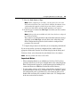
5
57
Select the Printer Definition subcomponent to display its panel. The
Printer Definition defines the printer type to be used by a particular print
session.
Printer
Definition
icon
Definition Name panel
6
Click the Add New Item button. The Printer Type Definition box appears.
7
Enter the Printer name and the Code Page and Command Set it uses. Click
OK.
8
If you need to modify a previously configured Printer Definition, doubleclick the Definition Name on the Definition Name panel. For more
information on how to make changes, consult the online help.
Configuring Host Print
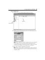
9
58
Click the Sessions icon to display its panel. This subcomponent defines
print sessions, print queues and the server you require for printing your
job.
Sessions
icon
Session Name panel
10
To add a session, click the Add New Items button. The Session Parameters
box appears. From the Session Parameters box, set parameter values or
change default values as required. Click OK.
Chapter Five
Remote Operation
T
HIS CHAPTER DESCRIBES HOW TO USE SEVERAL EICONCARD
commands for remote operations from a workstation. It also discusses
remote configuration under Windows 2000.
Remote Eiconcard Commands
60
Remote Eiconcard Commands
A number of Eiconcard commands can be run remotely from a LAN
workstation to operate on a specific gateway PC. These commands fall into
three groups:
• Status commands
• Administration commands
• NetView commands
Note These Eiconcard commands are included with the Eiconcard LAN
Client, a separate product. Refer to the Eiconcard LAN Client documentation
for full details on using the remote commands listed here.
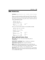
Status Commands
Status commands allow workstation users to obtain status and statistics for any
gateway to which they are attached (with ECLAN USE). This gives the user
access to:
ECCARD STATUS
The ECCARD STATUS command provides a list of Eiconcards and their ports,
detailing hardware configuration information based on the values entered in
the Eiconcard Configuration Program.
ECMODULE
The ECMODULE command is used to examine the protocol information
streaming through the gateway, and to provide statistical information about the
various connections.
ECVER
ECVER scans the specified drive or folder for any Eicon Networks software,
and displays the location and version number of that software.
Remote Eiconcard Commands
61
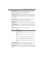
Administration Commands
Administration commands allow workstation users to control dialing and SNA
resources on any gateway to which they are attached (with ECLAN USE). The
following commands can be issued:
ECDIALER
The ECDIALER command enables you to make and receive calls, display
status information, and to hang up calls.
ECSNA
The ECSNA command enables you to create, configure, activate, and
deactivate SNA Nodes and logical Units.
Note Install these commands with caution. Since they allow direct control of
the gateway functions, inappropriate use of these commands may interfere with
the operation of the gateway. For example, the ECSNA command has options
that allow it to start, stop, and reconfigure Nodes. Any one of these options
could interrupt gateway operations for other users on the LAN.
The best way to make these commands accessible on the LAN is to install them
in a protected folder on the file server. This gives only authorized users easy
access to them from anywhere on the LAN.
NetView Commands
NetView commands enable you to use Eicon’s SNA network management
support (Netview Support must be configured on the gateway PC).
ECNETV
ECNETV is the SNA Network Management Support Console. It runs from a
Windows Command Prompt, or a DOS or OS/2 command line. It enables you
to build and send operator-generated alerts, display Response-Time monitor
(RTM) and RECFMS statistic data displays, and capture RTM and RECFMS
data to disk or printer. It emulates the TEXT mode feature of the IBM 3274/
3174 control unit.
ECRUNCMD
ECRUNCMD is a DOS or OS/2 application that is written specifically to
interface with NetView’s RUNCMD. it allows a host terminal to use NetView
or Net/Master to issue commands on the gateway or a workstation.
Remote Configuration
62
Remote Configuration
It is possible to use the Eicon Configuration Program to configure the Eicon
SNA Gateway from a remote system. You can do so:
• From a remote PC on the LAN (you must have administrator rights to both
the gateway and the remote PC)
• From another Eicon SNA Gateway on the LAN
Both systems must be running a Windows-based operating system.
➤ To configure the gateway PC from a remote PC:
1
2
Open Explorer and locate the gateway PC on your LAN.
3
Right-click the installation directory icon and select Map Network Drive
from the pop-up menu. The Map Network drive box appears.
4
5
Choose a drive letter that is not in use and click OK.
6
Run the Eicon Configuration Program (the file name is ECADMIN.EXE).
The Eicon Configuration Program appears, but the Navigator is blank.
7
Select the option Select Computer from the File menu. The Select
Computer box appears.
8
Enter the Windows 2000 Server name of the gateway PC and click OK
(this name is visible in the Computer Name parameter in the Eicon
Configuration Program). The configuration of the gateway PC appears in
the Navigator.
9
You can now modify the configuration of the gateway PC. Click the Save
button and close the program when done.
Double-click the icon for the gateway PC. Locate the installation directory
for the Eicon SNA Gateway software (the default is C:\EICON).
Open the newly-assigned drive. A window containing the contents of the
gateway installation directory appears.
Remote Configuration
63
➤ To configure the gateway PC from another Eicon SNA Gateway:
1
2
Run the Eicon Configuration Program.
3
Enter the Windows 2000 Server name and click OK (this name is visible
in the Computer Name parameter in the Eicon Configuration Program).
4
A second copy of the Eicon Configuration Program appears, with the
name of the gateway PC in the title bar. You can now modify the
configuration of the gateway PC. Click the Save button and close the
program when done.
Select the option Select Computer from the File menu. The Select
Computer box appears.
Chapter Six
Eiconcard Commands
T
HIS CHAPTER PRESENTS THE COMMAND LINE UTILITIES FOR THE
Eiconcard in alphabetical order. It explains how each command is used
and defines all associated parameters. Issue these commands from the
command line prompt on your gateway PC.
Overview of the Command Line Utilities
65
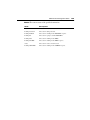
Overview of the Command Line Utilities
The command line utilities described in this chapter are briefly summarized
below. Commands are described in separate sections which are presented in
alphabetical order in this chapter.
ECADMIN
This command starts the Eicon Configuration Program. You can also start the
Eicon Configuration Program from the Start menu or from the Control Panel.
ECCARD
The ECCARD START command loads the ELMs (Eicon Loadable Modules)
or ERMs (Eicon Relocatable Modules) and starts the Eiconcard. ECCARD can
also be used to stop the Eiconcard, view its status, and dump the contents of
its memory to a file for analysis.
ECDIALER
This command is used to control the Eiconcard dialer and physical layer
connections using internal or external modems. ECDIALER instructs the
Eiconcard to make calls, answer calls, and to display status information.
ECHP
This command is used to start, stop and view the status of host print sessions.
ECMODULE
If you need to monitor the data communications traffic going through the
gateway PC, ECMODULE lets you analyze different levels of protocols.
ECMODULE is not required to run the gateway PC; it is a diagnostic tool.
The ECMODULE command is explained in detail in “ECMODULE
Command” on page 98.
ECNCBLOG
ECNCBLOG is a diagnostic utility used to trace NCBs (Network Control
Blocks) sent to the Eiconcard.
ECSERVER
ECSERVER (Eiconcard LAN Server) allows the gateway PC to provide
communications services to workstations on the local area network (LAN).
Overview of the Command Line Utilities
66
ECSNA
This command is used to start, stop and view the status of SNA resources (nodes
and Logical Units) on the Eiconcard.
ECVER
The ECVER command scans your network server or local hard drive for any
Eicon Networks software.
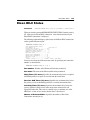
ECCARD: Starting the Eiconcards
67
ECCARD: Starting the Eiconcards
Executable
ECCARD.EXE
Purpose
Starts, stops, and monitors the Eiconcard and its associated protocols.
Commands
ECCARD
Parameters
START
[/Eiconcard n] [/Mail m]
[/Ncb n] [/Show] [/Flash]
START
/Port p | portname
STOP
[/Eiconcard n] [/Yes]
STOP
/Port p | portname [/Yes]
DUMP
/Eiconcard n
[/Binary dumpfile] [/Yes]
LIST
[/Eiconcard n]
STATUS
[/Eiconcard n]
START
Starts the specified Eiconcard or port, and all X.25
and Frame Relay ports with the Auto-Activate
Ports option selected. If no Eiconcard is specified,
all Eiconcards are started. All configuration
information is taken from the registry.
STOP
Stops the specified Eiconcard or port. Stopping the
last or only port on an Eiconcard does not stop the
Eiconcard itself. You must use the command
ECCARD STOP to stop the Eiconcard.
DUMP
Dumps Eiconcard memory to disk. Using
ECCARD DUMP disconnects any active
connections and stops only the specified Eiconcard.
LIST
Displays information on each Eiconcard protocol
executable as if it were started, but does not actually
run the executable.
STATUS
Provides information on the Eiconcard(s).
/Eiconcard n
Indicates the number (n) of the Eiconcard to start,
stop, or dump when you have more than one
Eiconcard installed in your gateway PC. This
parameter is mandatory only with the DUMP option.
For other options, if it is not specified, the action is
performed on all Eiconcards.
/Mail m
The size (m) of the MAIL trace buffer on the
Eiconcard, in kilobytes, ranging from 1 to 64. This
is used to perform an internal mail trace when
directed to do so by a representative of Eicon
Networks Customer Services.
ECCARD: Starting the Eiconcards
68
/Ncb n
The size (n) of the NCB trace buffer on the
Eiconcard, in kilobytes, ranging from 1 to 64. This
is used to perform an internal NCB trace when
directed to do so by a representative of Eicon
Networks Customer Services.
/Show
Displays detailed information on each Eiconcard
protocol module.
/Port p |
portname
Indicates the port number (p) or the port name
(portname) of the Eiconcard to start or stop. This
parameter is mandatory if acting on a specific port.
/Yes
Suppresses “Y/N” messages from the ECCARD
STOP or ECCARD DUMP commands. This is
useful for batch files.
/Binary dumpfile The Eiconcard dump filename if the default
DUMP*.* file is not used. Specify the full path if
the file is not in the current directory.
Auto-Activate Ports
Each X.25 or Frame Relay port that you configure as Auto-Activate is
automatically started when ECCARD START is issued. This option saves you
having to start each port individually with the ECCARD START /P command.
ECCARD: Starting the Eiconcards
69
Using ECCARD
The following examples show how the different ECCARD options can be used.
ECCARD START
The ECCARD START command starts the specified Eiconcard or port. When
you start an Eiconcard all X.25 and Frame Relay ports are automatically started
unless you turn off the Auto-activate option (see previous topic).
Consider these examples:
ECCARD START
Starts all Eiconcards in the gateway PC.
ECCARD START /SHOW
Starts all Eiconcards and displays each software module as it is loaded
onto the Eiconcard.
ECCARD START /E 4
Starts Eiconcard #4.
ECCARD STOP
Stops the specified Eiconcard or port. Stopping an Eiconcard halts all ports on
it. Any active connections are lost. Stopping the last or only port on an
Eiconcard does not stop the Eiconcard itself; you must explicitly stop it.
Examples
ECCARD STOP /E 3
Stops Eiconcard #3 and displays the following:
Do you really want to stop CARD 3? (Y/N) Y
Eiconcard 3 stopped.
Command completed successfully.
ECCARD STOP /E 2 /Y
Stops Eiconcard #2, and suppresses the Yes/No message:
Eiconcard 2 stopped.
Command completed successfully.
ECCARD: Starting the Eiconcards
70
ECCARD DUMP
The DUMP command saves the contents of Eiconcard memory to disk for later
analysis. Running ECCARD DUMP disconnects all active connections
through the gateway and stops the Eiconcard.
If you are having trouble establishing a connection and are unable to find the
source of the problems, a DUMP can be useful. In most cases, the DUMP is
done under the advice or supervision of an Eicon Networks representative. The
DUMP file can then be analyzed, and a solution found to your problem.
If you are dumping the contents of an Eiconcard for the first time, the default
filename is DUMPx.001, where x is the number of the Eiconcard. For each
subsequent dump, the file extension is incremented by 1: DUMP1.001,
DUMP1.002, DUMP1.003, etc. If you delete all the DUMP files from the target
directory, the counter will restart at 001.
Example
ECCARD DUMP /E 2 /B TESTDUMP.DMP
Dumps Eiconcard #2 to a file called TESTDUMP.DMP.
ECCARD LIST
The ECCARD LIST command displays information on each Eiconcard
protocol executable as if it were being started, but does not actually run the
executable. This is useful to determine if the right software will be started based
on the configuration selected.
Example
ECCARD LIST
ECCARD STATUS
The ECCARD STATUS command provides a list of Eiconcards and their ports,
detailing hardware configuration information based on the values entered in
the Eiconcard configuration file.
ECCARD: Starting the Eiconcards
71
When you issue the ECCARD STATUS command, detailed information about
the Eiconcard is displayed. The following is a sample display:
Eiconcard Configuration :
Card Type
ID
Status
PCB
IO Port IRQ Address
------------------------------------------------------------------1
C21
BAB152C7 LOADED
800268.1
210
3
n/a
Eiconcard Port mapping :
Card Port Port name
Protocol
------------------------------------1
01
P1
X25
Eiconcard Memory status :
Card Type
Free
Total
------------------------------------1
C21
293 K
512 K
Command completed successfully.
The following table explains the headings in this display.
Parameter
Description
Card
Eiconcard card number.
Type
Type of Eiconcard installed in the gateway PC and configured by the
Eicon Configuration Program.
ID
Unique identifier hard-coded on the Eiconcard. (Not applicable to
Eiconcard S50/S51/S52).
Status
Status of the Eiconcard. Refer to the table on the next page for a detailed
list of all the different Eiconcard status values.
PCB
Printed Circuit-Board number: This is an identification code showing
the revision number of the Eiconcard in use. If the software does not
detect a PCB number, you must check the Eiconcard itself for a
physically engraved number.
I/O Port
I/O port memory address of the Eiconcard. Make sure that no other
peripheral is using this I/O port address.
IRQ
Interrupt Request Level used by the Eiconcard. Make sure that no other
peripheral is using this IRQ on an ISA bus (AT or PC bus).
Address
Memory segment used by the Eiconcard. Make sure that no other
peripheral is using this memory segment. (Not applicable to
Eiconcard C20/C21).
Port
Port number on the specified Eiconcard.
Port Name
The name of the port on the specified Eiconcard.
Protocol
The protocol currently in use by the specified port.
Free
The available RAM Memory on the Eiconcard.
Total
The RAM Memory capacity of the Eiconcard.
ECCARD: Starting the Eiconcards
72
The following table lists the different Eiconcard status values:
Status Value
Description
DETECTED
The Eiconcard I/O Port Address and Memory Segment has been properly
configured, but the Card Identification (type) or IRQ test has failed or has
not yet been performed.
DUMPING
The contents of the Eiconcard's memory is currently being dumped to
disk.
HALTED
All Eiconcard tests have been completed successfully, the hardware
settings are correct, and the size of the Eiconcard's memory has been
determined. The Eiconcard has now been stopped, and must be restarted
to be used.
IDLE
This Eiconcard has not been properly configured. Make sure you have
the correct I/O, IRQ, and Memory Segment values configured for this
Eiconcard.
LOADED
The Eiconcard has been started, is functioning, and can be used for
communication, assuming the Ports have been activated.
LOADING
The necessary protocol executables are being started onto the Eiconcard.
TESTING
An Eiconcard test is now in progress, or is in an intermediate state of the
start process.
TESTED
The Eiconcard has tested successfully.
Examples
The following example illustrates how to use ECCARD STATUS.
ECCARD STATUS
Provides detailed information on all Eiconcards in the gateway PC.
ECCARD: Starting the Eiconcards
73
ECCARD Error Level Values
ECCARD returns the following error levels.
Error Level Description
0
SUCCESS. The command was completed successfully.
1
WARNING. A warning was displayed while the command was running. The
command was executed anyway.
2
PARTIAL. The command was partially completed. (This occurs when using
the ECCARD START command to run all Eiconcards at once, but some
Eiconcards could not be started.)
3
ABORT. The CONTROL-C or CONTROL-Break key combinations were
pressed while an ECCARD command was executing, or the command was
canceled from an input prompt such as: Binary dump file DUMPCARD.DAT
already exists, do you want to overwrite? (Y/N) N.
4
FAILED. The command failed. For ECCARD START (without
/Eiconcard n), this happens when ALL the Eiconcards specified in the
Eiconcard configuration file could not be started.
ECDIALER: Using a Modem
74
ECDIALER: Using a Modem
Executable
ECDIALER.EXE
Purpose
Dials, hangs up, monitors, and configures the Eiconcard dialers. This
command can also be used to determine the state of the hardware link.
Preloaded
Executables
You must have already run ECCARD START for this executable to run
successfully.
Commands
Use the command appropriate to your operating system.
Parameters
ECDIALER STORE
[/Main n] [/ALternate n] [/NType t]
[/NPlan p] [/SAddr a] [/SType t]
[/Tns t] [/BCtype b]
[/Port n|portname] [/Outfile f]
ECDIALER DIAL
[/NUmber n] [/NType t] [/NPlan p]
[/SAddr a] [/SType t] [/Tns t]
[/BCtype b] [/Port n|portname]
[/Outfile f]
ECDIALER EXEC
/File script [/Port n|portname]
[/Outfile f]
ECDIALER ANSWER
/Enable|/Disable [/Port n|portname]
[/Outfile f]
ECDIALER HANGUP
[/Port n|portname] [/Outfile f]
ECDIALER STATUS
[/Port n|portname] [/Outfile f]
ECDIALER LINE
/ON|/OFF [/Port n|portname]
[/Outfile f]
ANSWER
Use this option for all dialer types except Direct.
Enables or disables the dialer from answering
incoming calls.
For ISDN cards configured as a 2B terminal, where
both ports can accept the incoming call, the call will
always be answered by port 1.
DIAL
Use this option for Hayes AT, ISDN, and V.25bis
dialer types.
Dial the telephone number specified with the /NU
parameter. If no number is specified, dial the Main
(or Alternate number if there is one) that has been
STOREd. If the Retry parameter has been enabled
in the Eicon Configuration Tool, then dialing is
repeated until successful or the Retry counter has
expired.
EXEC
Supported by Hayes AT dialers only. Execute a script
for programming an external modem.
ECDIALER: Using a Modem
Parameters
(continued)
75
HANGUP
Use this option for all dialer types except Direct.
Hangs up the current connection.
LINE
Defines the setting of the Data Rate Select (DRS)
signal on an RS-232 interface (Direct Dialer only).
Not supported by ISDN dialers.
STATUS
Performs the same function as the
ECMODULE DIALER STATUS command.
STORE
Use this option for Hayes AT, ISDN, and V.25bis
dialer types.
Store the primary or alternate telephone number to
call. The options you specify with this command
override the settings in the Eicon Configuration Tool
command file.
Note: ISDN users do not have the option to store an
alternate number.
/ALternate n
This parameter is not available for ISDN dialer
types.
Sets the alternate telephone number. This is dialed
when the ECDIALER DIAL command is issued and
the primary number dialed is busy.
/BCtype bearer
ISDN only. Possible values: 64K, 56K, or Packet.
/Disable
Disable the dialer from answering any incoming
calls.
/Enable
Enable the dialer to answer any incoming calls.
/File script
Filename of the ECDIALER script file to execute.
Only valid for AT dialers.
/Main n
Sets the main telephone number. This is the first
number dialed when the ECDIALER DIAL
command is issued without a number parameter. On
ISDN this option is not needed for packet calls.
/NUmber n
Dial the override number n, regardless of what is
stored as the Primary or Alternate phone number. On
ISDN this option is not needed for packet calls.
/ON
Switches the Data Rate Select (DRS) line to ON.
This option is not available for ISDN Eiconcards.
/OFF
Switches the Data Rate Select (DRS) line to OFF.
This option is not available for ISDN Eiconcards.
/Outfile f
Write the display to a file. Use a valid name for f.
Note: When used on a script file, the PAUSE
command will not function.
/Port p |
portname
The Eiconcard port or portname through which you
want to dial. Port 1 is the default.
ECDIALER: Using a Modem
Parameters
(continued)
76
/NType type
Number type. Possible values are: Unknown,
International, NAtional, NEtSpecific, Subscription,
Abbreviated. This list varies from one country to
another. (ISDN dialer only.)
/NPlan plan
Numbering plan. Possible values are: Unknown,
ISDN, Data, Private, Telex, NAtional. This list
varies from one country to another. (ISDN dialer
only.)
/SAddr subaddr
The subaddress of the terminal being called. (ISDN
dialer only.)
/SType subtype
Possible values: NSAP, USER, OSI. This list varies
from one country to another. (ISDN dialer only.)
/Tns t
Transit Network Selection. Allows you to specify
which long-distance carrier will be used to carry the
call. (ISDN dialer only.)
You can use ECDIALER to make and receive calls, display status information,
and hang up the line.
ECDIALER also supports the use of modem scripts that tell your dialer what
information to send in response to specific prompts. Scripts can be written to
automate a wide range of communications functions. Use the ECDIALER
Script facility for AT Dialer and programming of external asynchronous/
synchronous Hayes compatible modems.
ECDIALER: Using a Modem
77
Using ECDIALER
The following examples illustrate how to use the ECDIALER command.
ECDIALER STORE /P 2 /M 5551212
ECDIALER DIAL /P 2
Stores the primary phone number for port #2 and then dials it.
ECDIALER STORE /P 3/M 5551212 /AL 18005550000
ECDIALER DIAL /P 3
Instructs the dialer associated with port 3 to dial 555-1212, and if that
number is occupied to dial 1-800-555-0000.
ECDIALER ANSWER /E /P 3
Enables port #3 to accept incoming calls.
ECDIALER EXEC /F LOGON.SCR /P 2
Executes the script file, LOGON.SCR, on the dialer connected to port 2
on the gateway.
ECDIALER and ISDN
78
ECDIALER and ISDN
This section contains information about using the ECDIALER command to
control the Eiconcard with ISDN support.
Using ECDIALER with NI-1 (North America)
This section describes how to make an ISDN connection to an NI-1 switch.
X.25 on the D-Channel
If a port on the Eiconcard has been configured as a D-channel to carry X.25
data, the only ECDIALER command that you can use on that port is the
ECDIALER STATUS command.
ISDN NI-1 Parameters
The table below lists all the ISDN NI-1 specific parameters for ECDIALER.
Parameter
Explanation
/BCtype bearer
Defines the Bearer Capability (i.e., the information-transfer rate
and mode). Possible values are 56K, 64K (default), or Packet.
56K and 64K are for circuit-switched services, while Packet is
the equivalent of 64K for packet-switched services.
/Main n
Stores the main telephone number. This is the first number
dialed when you issue the ECDIALER DIAL command without
a number parameter. This option is not required for packet calls
when connecting to ISDN through an NI-1 type switch.
/NUmber n
Dials the number specified.
/NType type
Specifies the remote number type, Abbreviated, International,
National, Netspecific, Subscriber, or Unknown (default),
assigned to the called party by its local telephone company.
/NPlan plan
Numbering plan for the ISDN dialer. Possible values are
Unknown, ISDN (default), Data, Private, Telex, or National.
/SAddr subaddr
Provides the subaddress to further identify the remote terminal
on the ISDN Basic Rate Interface. If two terminals share the
same directory number, the subaddress identifies which terminal
will answer a particular incoming call.
/SType subtype
The types of subaddress used, NSAP (default) or User. If you
include this option, you must also use the /SAddr option.
ECDIALER and ISDN
79
Parameter
Explanation
/Tns tns
The transit network selector allows you to specify the transit
carrier to be used on long-distance calls.
/Port p | portname
The Eiconcard port number or port name through which you
want to dial. Port 1 is the default. With ISDN connections, this
refers to the Eiconcard channel you are using.
ECDIALER STORE
ECDIALER STORE
[/Main n] [/ALternate n] [/NType t] [/NPlan p]
[/SAddr a] [/SType t] [/Tns t] [/BCtype b]
[/Port n|portname] [/Outfile f]
ECDIALER STORE replaces whatever value was previously stored.
ECDIALER DIAL
ECDIALER DIAL
[/NUmber n] [/NType t] [/NPlan p] [/SAddr a]
[/SType t] [/Tns t] [/BCtype b]
[/Port n|portname] [/Outfile f]
To dial a number that has been configured or that has already been stored using
the ECDIALER STORE command, issue the following command:
ECDIALER DIAL
/P port
ECDIALER ANSWER
ECDIALER ANSWER
/Enable | /Disable /Port port
Enables or disables the dialer to answer any incoming calls. Answer Mode
allows a correctly configured port to answer a call.
ECDIALER HANGUP
ECDIALER HANGUP
/Port port
This command allows you to hangup an ISDN connection on the specified port.
ECDIALER STATUS
ECDIALER STATUS
/Port port
ECDIALER STATUS displays summary information on all ports. Specify a
port name or number to see detailed information about a specific port.
ECDIALER and ISDN
80
Using ECDIALER with TPH1962 (Australia)
This section describes how to make an ISDN connection to the TPH1962
switch type used in Australia.
X.25 on the D-Channel
If a port on the Eiconcard has been configured as a D-channel to carry X.25
data, the only ECDIALER command that you can use on that port is the
ECDIALER STATUS command. No other ECDIALER commands are
supported for X.25 D-channels.
ISDN TPH1962 Parameters
The following table lists all the ISDN TPH1962 specific parameters for
ECDIALER.
Parameter
Explanation
/Main n
Stores the main telephone number. This is the first number dialed
when you issue the ECDIALER DIAL command without a
number parameter. This option is not required for packet calls
when connecting to ISDN through a TPH1962 type switch.
/NUmber n
Dials the number specified, regardless of what is stored as the
main telephone number.
/NType type
Specifies the remote number type, Abbreviated, International,
National, Netspecific, Subscriber, or Unknown (default),
assigned to the called party by its local telephone company.
/NPlan plan
Numbering plan for the ISDN dialer. Possible values are
Unknown, ISDN (default), Data, Private, Telex, or National.
/SAddr subaddr
Provides the subaddress to further identify the remote terminal on
the ISDN Basic Rate Interface. If two terminals share the same
directory number, the subaddress identifies which terminal will
answer a particular incoming call.
/SType subtype
The types of subaddress used, NSAP (default) or User. If you
include this option in the command, you must also use the /SAddr
option.
/BCtype bearer
Defines the Bearer Capability (i.e., the information-transfer rate
and mode). Possible values are 56K, 64K (default), or Packet. 56K
and 64K are for circuit-switched services, while Packet is the
equivalent of 64K for packet-switched services.
/Port p |
portname
The Eiconcard port number or port name through which you want
to dial. Port 1 is the default. With ISDN connections, this refers
to the Eiconcard channel you are using.
ECDIALER and ISDN
81
ECDIALER STORE
ECDIALER STORE
[/Main n] [/ALternate n] [/NType t] [/NPlan p]
[/SAddr a] [/SType t] [/Tns t] [/BCtype b]
[/Port n|portname] [/Outfile f]
ECDIALER STORE permanently replaces whatever value was previously
configured or stored.
ECDIALER DIAL
ECDIALER DIAL
[/NUmber n] [/NType t] [/NPlan p] [/SAddr a]
[/SType t] [/Tns t] [/BCtype b]
[/Port n|portname] [/Outfile f]
To dial a number that has been configured or that has already been stored using
the ECDIALER STORE command, enter the following command:
ECDIALER DIAL /P port
ECDIALER ANSWER
ECDIALER ANSWER
/Enable | /Disable /Port port
Enables or disables the dialer to answer any incoming calls. Answer Mode
allows a correctly configured port to answer a call.
ECDIALER HANGUP
ECDIALER HANGUP
/Port port
This command allows you to hangup an ISDN connection on the specified port.
ECDIALER STATUS
ECDIALER STATUS
/Port port
ECDIALER STATUS displays summary information on all ports. Specify a
port name or number to see detailed information about a specific port.
ECDIALER and ISDN
82
Using ECDIALER with 5ESS (AT&T)
This section describes how make an ISDN connection to the 5ESS switch type.
ISDN AT&T 5ESS Parameters
The following table lists all the ISDN AT&T 5ESS specific parameters for
ECDIALER:
Parameter
Explanation
/Main n
Stores the main telephone number. This is the first number dialed
when you issue the ECDIALER DIAL command without a
number parameter. This option is not required for packet calls
when connecting to ISDN through a 5ESS type switch.
/NUmber n
Dials the number specified, regardless of what is stored as the
main telephone number.
/SAddr subaddr
Provides the subaddress to further identify the remote terminal
on the ISDN Basic Rate Interface. If two terminals share the same
directory number, the subaddress identifies which terminal will
answer a particular incoming call.
/SType subtype
The types of subaddress used, NSAP (default) or User. If you
include this option in the command, you must also use the /SAddr
option.
/BCtype bearer
Defines the Bearer Capability (i.e., the information-transfer rate
and mode). Possible values are 56K, 64K (default), or Packet.
56K and 64K are for circuit-switched services, while Packet is
the equivalent of 64K for packet-switched services.
/Port p | portname
The Eiconcard port number or port name through which you want
to dial. Port 1 is the default. With ISDN connections, this refers
to the Eiconcard channel you are using.
ECDIALER STORE
ECDIALER STORE
[/Main n] [/ALternate n] [/NType t] [/NPlan p]
[/SAddr a] [/SType t] [/Tns t] [/BCtype b]
[/Port n|portname] [/Outfile f]
ECDIALER STORE permanently replaces whatever value was previously
configured or stored.
ECDIALER and ISDN
83
ECDIALER DIAL
ECDIALER DIAL
[/NUmber n] [/NType t] [/NPlan p] [/SAddr a]
[/SType t] [/Tns t] [/BCtype b]
[/Port n|portname] [/Outfile f]
To dial a number that has been configured or that has already been stored using
the ECDIALER STORE command, enter the following command:
ECDIALER DIAL /P port
ECDIALER ANSWER
ECDIALER ANSWER
/Enable | /Disable /Port port
Enables or disables the dialer to answer any incoming calls. Answer Mode
allows a correctly configured port to answer a call.
ECDIALER HANGUP
ECDIALER HANGUP
/Port port
This command allows you to hangup an ISDN connection on the specified port.
ECDIALER STATUS
ECDIALER STATUS
/Port port
ECDIALER STATUS displays summary information on all ports. Specify a
port name or number to see detailed information about a specific port.
ECDIALER and ISDN
84
Using ECDIALER with EuroISDN
This section describes how make an ISDN connection to the EuroISDN switch
type.
X.25 on the D-Channel
If a port on the Eiconcard has been configured as a D-channel to carry X.25
data, the only ECDIALER command that you can use on that port is the
ECDIALER STATUS command. No other ECDIALER commands are
supported for X.25 D-channels.
ISDN EuroISDN Parameters
The following table lists all the ISDN EuroISDN parameters for ECDIALER:
Parameter
Explanation
/Main n
Stores the main telephone number. This is the first number dialed
when you issue the ECDIALER DIAL command without a
number parameter. This option is not required for packet calls
when connecting to ISDN through an EuroISDN type switch.
/NUmber n
Dials the number specified, regardless of what is stored as the
main telephone number.
/NType type
Specifies the remote number type, Abbreviated, International,
National, Netspecific, Subscriber, or Unknown (default), assigned
to the called party by its local telephone company.
/NPlan plan
Numbering plan for the ISDN dialer. Possible values are
Unknown, ISDN (default), Data, Private, Telex, or National.
/SAddr subaddr
Provides the subaddress to further identify the remote terminal on
the ISDN Basic Rate Interface. If two terminals share the same
directory number, the subaddress identifies which terminal will
answer a particular incoming call.
/SType subtype
The types of subaddress used, NSAP (default) or User. If you
include this option. you must also use the /SAddr option.
/Tns tns
The transit network selector allows you to specify the transit
carrier to be used on long-distance calls.
/Port p |
portname
The Eiconcard port number or port name through which you want
to dial. Port 1 is the default. With ISDN connections, this refers
to the Eiconcard channel you are using.
/BCtype bearer
Defines the Bearer Capability (i.e., the information-transfer rate
and mode). Possible values are 56K, 64K (default), or Packet. 56K
and 64K are for circuit-switched services, while Packet is the
equivalent of 64K for packet-switched services.
ECDIALER and ISDN
85
ECDIALER STORE
ECDIALER STORE
[/Main n] [/ALternate n] [/NType t] [/NPlan p]
[/SAddr a] [/SType t] [/BCtype b] [/Port n|portname]
[/Gateway g] [/Outfile f]
ECDIALER STORE permanently replaces whatever value was previously
configured or stored.
ECDIALER DIAL
ECDIALER DIAL
[/NUmber n] [/NType t] [/NPlan p] [/SAddr a]
[/SType t] [/Tns t] [/BCtype b]
[/Port n|portname] [/Outfile f]
To dial a number that has been configured or that has already been stored using
the ECDIALER STORE command, enter the following command:
ECDIALER DIAL /P port
ECDIALER ANSWER
ECDIALER ANSWER
/Enable | /Disable /Port port
Enables or disables the dialer to answer any incoming calls. Answer Mode
allows a correctly configured port to answer a call.
ECDIALER HANGUP
ECDIALER HANGUP
/Port port
This command allows you to hangup an ISDN connection on the specified port.
ECDIALER STATUS
ECDIALER STATUS
/Port port
ECDIALER STATUS displays summary information on all ports. Specify a
port name or number to see detailed information about a specific port.
ECDIALER and ISDN
86
ECDIALER Script Language
A modem script tells your dialer what information to send in response to
specific cues. A script is like a program, and elaborate scripts can be written
to automate a wide range of communications functions. ECDIALER script is
used for the AT Dialer and programming of external asynchronous/
synchronous Hayes compatible modems.
The ECDIALER Script feature supports most external modems. Use any
ASCII text editor to create the script file.
Blank lines are accepted in the script. All commands must start in the first
column.
Valid commands are as follows:
:label When you use a GOTO label command, the script jumps to the specified
label and continues execution from there. A label is any alphanumeric ASCII
string with a colon in the first position. The “—” (dash) and “_” (underscore)
characters can also be used for the label.
*comment Any script line starting with an asterisk (*) in the first column is
treated as a comment, and ignored by the script. A comment is used only for
your information.
CLOSE_COMM This command closes the Eiconcard port that is connected
to the external modem. This does not hang up the modem. CLOSE_COMM
must be the last statement executed when you are finished with the port.
DIAL number This command dials the specified number. Success or failure
can be tested with the IFERROR statement. A MATCH command is commonly
used directly after DIAL to look for the CONNECT message from the modem.
GOTO label This command causes processing of the script file to continue
at the specified label. The label can be forward or backward, and can thus be
used for looping.
IFERROR label This command causes execution of the script file to continue
from the specified label if an error occurred during one of the following
commands: MATCH, DIAL, OPEN_COMM, or TYPE. Use IFERROR
immediately after these commands to test for errors.
MATCH string This command pauses execution of the script file until input
is received that matches the specified string. For instance, a Hayes modem
ECDIALER and ISDN
87
usually returns “OK” to acknowledge a command. Use MATCH “OK” to wait
for the “OK” string. The string must be enclosed in quotation marks. MATCH
waits the number of seconds specified in a previous TIMEOUT command. Use
IFERROR directly following MATCH to test for success or failure. This
command reads and ignores any characters before the match is found or a
timeout occurs.
OPEN_COMM This command initializes the Eiconcard for communication
with the external modem. The initialization values for this command are
specified with the five SET_xxxx commands. Success or failure is determined
with the IFERROR command.
PAUSE Pauses execution of the script file until any key is pressed on the
keyboard. This is useful when debugging a script.
PRINT string Displays the specified string on the screen.
SET_DATA_BITS n This command sets the number of data bits put into effect
by a subsequent OPEN_COMM command. Valid values for “n” are 7 or 8 data
bits. The default is 8 data bits.
This is the asynchronous data bit setting used by the Eiconcard Hayes dialer
port to communicate with an external modem.
SET_PARITY n Selects the parity of the connection put into effect by a
subsequent OPEN_COMM command. Valid values for n are: NO_PARITY,
EVEN_PARITY, or ODD_PARITY. The default is NO_PARITY.
This is the parity setting used by the Eiconcard Hayes dialer port to
communicate with an external modem.
SET_PORT n Specifies the Eiconcard port to use when communicating with
a modem. SET PORT takes effect when an OPEN_COMM command is
executed. Valid values for n range from 1 to 48. The default is 1.
SET_SPEED n Sets the bits per second (bps) rate put into effect by a
subsequent OPEN_COMM command. Valid values are: 1200, 2400, 4800,
9600. The default is 2400 bps.
This is the speed setting used by the Eiconcard Hayes dialer port to
communicate with an external modem.
SET_STOP_BITS n Selects the number of stop bits. Set n to 1 or 2 stop bits.
By default, 1 stop bit is used. This command is not taken into account by
ECDIALER and ISDN
88
OPEN_COMM, but you must have the same stop bit setting as the computer
to which you are connected. This is the stop bits setting used by the Eiconcard
Hayes dialer port to communicate with an external modem.
TIMEOUT n This command sets the timeout value in seconds for the MATCH
command. Default is 15 seconds.
TYPE string | hex,... This command sends a string to the modem. The string
must be enclosed in quotation marks (single or double) and can include any
text or hexadecimal value. If you need to insert control codes, enter them in
hexadecimal. Here is an example of TYPE:
TYPE "AT\S",07,'ATDT5551212',0d
Success or failure of this command can be tested with the IFERROR command.
WAIT n This command causes the execution of the script file to pause for n
seconds.
Modem Considerations (Hayes AT)
If the Dialer type is configured as “HAYES AT” in the ECCARD CONFIG
command, certain parameters must be set on your external modem. The table
below lists settings and modes to which a Hayes-compatible modem should be
set in order to interoperate successfully with the gateway.
AT Command
Description
AT&F
Restores all factory defaults and deletes all stored numbers.
AT&C1
Sets the Data Carrier Detect (DCD) to track the data carrier from
the remote modem. DCD is on when the data carrier is detected.
AT&D2 or D3
Sets the Data Terminal Ready (DTR) mode so that the modem hangs
up, assumes command state, and disables auto-answer when an ONto-OFF transition of DTR is detected.
AT&M1 or &Q1
This sets the modem to synchronous mode 1. The call placement is
initiated using asynchronous methods, but the modem switches to
synchronous operation when the connection is fully established. The
modem returns to asynchronous mode when it detects an ON-toOFF transition on the DTR interchange circuit.
AT&S1or S2
Sets the Data Set Ready (DSR) to trade carrier. The DSR cannot be
changed from this mode if the modem is operating in synchronous
mode.
ECDIALER and ISDN
89
If the AT commands given above are not compatible with your modem, you
should determine, from your modem’s operating guide, the equivalent
commands used to control the following parameters:
Parameter
Settings Required
DTR on/off
The Data Terminal Ready signal will be turned off to cause the
modem to hang up. The modem should interpret DTR this way.
DSR on/off
The Data Set Ready signal is used to detect a connection. It should
be turned on only when data is ready to be sent (modem negotiation
complete).
Sync/Async mode
The modem must operate in asynchronous mode while in an off-line
command state. It must operate in synchronous mode from the time
the connection is fully established until the on-line data-transfer state
is terminated.
The Request-To-Send/Clear-To-Send (RTS/CTS) delay interval value may
also need to be adjusted. This value determines the delay time a modem uses
before turning on CTS after detecting an OFF-to-ON transition on RTS.
The RTS/CTS delay interval can be adjusted by adjusting the modem’s S26
register. If you are using a Hayes-compatible modem, this is achieved with the
AT command:
ATS26=x
where x is the value of the delay interval in increments of 10 ms.
If you do not own a Hayes compatible modem, consult your modem’s operating
guide for directions on how to adjust the interval between detection of the
Request-To-Send mode and enabling of the Clear-To-Send signal.
Sample Script
The ECDIALER script does three things:
• Initializes the Eiconcard for communications with the modem. This is done
with the SET_PORT, SET_DATA_BIT, SET_SPEED, and finally the
OPEN_COMM commands.
• Programs the modem.
• Calls the DATAPAC online service from Montreal. This is done with the
Type “ATDT8614750” command. When a connection is established, the
modem answers with a “CONNECT 2400” string.
ECDIALER and ISDN
90
The following is a sample script text for a Hayes-compatible modem. Use the
sample as a base for your own script, but change the settings to ones appropriate
for your own particular modem type.
****************************************************************
This script file is used to configure hayes-compatible modems.
****************************************************************
close_comm
set_port 3
set_speed 9600
set_parity NO_PARITY
set_data_bits 8
iferror bye_comm
print "Initialization successful "
wait 1
******************************************************************
The AT (ATtention code) is examined by modems which support
*
* auto bauding in order to determine the communications and
*
* parity setting of the DTE device. Modems which do not
*
* support auto bauding can only communicate at the configured
*
* speed and parity setting.
*
* Some modems may require that the ATtention code be sent twice.*
* If this is the case, repeat the sending of the ATtention code.
******************************************************************
type "AT",0d,0a
iferror bye_t1
timeout 15
match "OK"
iferror bye_m1
***************************************
* Programming modem
*
***************************************
***************************************
*** Initialize to factory settings ***
***************************************
type "AT&F",0d,0a
match "OK"
iferror FACTORY
***************************************
*** Set speaker volume to low
***
***************************************
type "ATL1",0d,0a
match "OK"
iferror ATFORM
***************************************
*** DCD setting AT&C1
***
*** DCD is asserted by modem only
***
*** if a data carrier which meets
***
*** the modems suitable criteria
***
*** is present. On some modems
***
*** the factory setting for DCD
***
*** to remain on at all times
***
*** disregarding the
***
*** state of the data carrier.
***
***************************************
type "AT&C1",0d,0a
match "OK"
iferror TELCO
wait 1
***************************************
*** DTR Setting AT&D2
***
*** Set modem to answer when DTR is ***
*** raised by the DTE and set to hangup*
*** to asynchronous command mode
***
*** when DTR switches from ON to OFF.**
***************************************
type "AT&D2",0d,0a
match "OK"
iferror TELCO
***************************************
*** ATS0 = 1”
***
ECDIALER and ISDN
*** Set modem to answer on the first ring.
***************************************
type "ATS0=1",0d,0a
match "OK"
iferror TELCO
***************************************
*** Asyn/Sync Mode Selection AT&M1 ***
***
***
*** Call is initiated in asynchronous**
*** mode. The modem will automatically*
*** switch to synchronous mode once the*
*** telephone connection is established.*
*** The factory setting for most modems*
*** is asynchronous.
***
***
***
***************************************
type "AT&M1",0d,0a
match "OK"
iferror TELCO
***************************************
*** DSR setting AT&S1
***
***
***
*** DSR is controlled by the modem. ***
*** With this setting, DSR is asserted*
*** when the modem completes answer ***
*** tone detection and training. If***
*** the modem hangups after dialing ***
*** and answer tone detection, this ***
*** setting is the cause. The factory*
*** setting for most modems is to
***
*** DSR at all times.
***
***
***
***************************************
type "AT&S1",0d,0a
match "OK"
iferror TELCO
***************************************
*** Write active configuration to
***
*** nonvolatile memory. These settings*
*** will be restored automatically ***
*** whenever the modem is turned on.***
***
***
***************************************
type "AT&W",0d,0a
match "OK"
iferror TELCO
goto bye
:TELCO
print "TELCO ERROR"
goto exit
:bye_t1
print "Error during modem programming. Type failed."
goto exit
:MODERR
print "Error while setting modulation for 1200 bauds"
goto exit
:FACTORY
print "Error while initializing to factory setting"
goto exit
:bye_m1
print "No answer from modem."
goto exit
:bye_comm
print "**** INIT ERROR !!"
goto exit
:bye
print "Modem programmed successfully"
:exit
91
ECHP: Monitoring Host Print Sessions
92
ECHP: Monitoring Host Print Sessions
Executable
ECHP.EXE
Purpose
Starts, stops and monitors the status of Host Print sessions.
Command
ECHP
START
STOP
STATUS [/S sessionname]
Parameters
START
Starts Host Print services.
STOP
Stops Host Print services.
STATUS
Displays a list of current Host Print sessions and
their status.
/S sessionname
The name of the Host Print session for which you
want the status to be displayed.
The ECHP program lets you activate and deactivate Host Print services. It also
lists Host Print sessions and Logical Units.
ECNCBLOG: Taking NCB Traces
93
ECNCBLOG: Taking NCB Traces
Executable
ECNCBLOG.EXE
Purpose
Starts the NCB trace utility.
Command
ECNCBLOG
-f logfile [-s tracebufsize]
[-l ncbdatalen] [-p processes]
[-t traceinfo]
Parameters
-f logfile
Specify the name of the logfile.
-s tracebufsize
Specify the length of trace buffer (default 64k).
-l ncbdatalen
Specify how much of the NCB data field to log
(default 64 bytes).
-p processes
Specify the number of processes to support
(default 4).
-t traceinfo
Specify what to display in the trace
(default 0x00003FF3).
Possible values for traceinfo.
0x00000001
Submitted NCB
0x00000002
Submitted NCB data
0x00000004
Completed NCB
0x00000008
Completed NCB data
0x00000010
NCB posted to application
0x00000020
NCB data posted to application
0x00000040
NCB given to application (through wait)
0x00000080
NCB data given to application
0x00000100
Open NCB session
0x00000200
Close NCB session
0x00000400
Discover Eiconcard LAN gateway
0x00000800
Set parameters
0x00001000
Get parameters
0x00002000
Application errors
Note: To get information on more than one trace at a time, you must add together the values for
traceinfo. For example, to receive trace information on Submitted NCBs and on Submitted NCB
data, you would specify a value of 0x00000003.
You must start the trace before you start the application that uses the ECNCB
API (e.g. Host Print). As long as it is running, ECNCBLOG will store a trace
of the NCBs in the specified logfile. Press CTRL-C to stop the trace.
ECSERVER: LAN Transport
94
ECSERVER: LAN Transport
Executable
ECSERVER.EXE
Purpose
Provides communications services to client workstations on the LAN.
Command
ECSERVER
[start]
stop
sessions <session #>
status [/Client name]
Parameters
start
Starts Eiconcard LAN Server.
stop
Stops Eiconcard LAN Server.
sessions
<session #>
Specifies the maximum number of sessions.
status
[/Client name]
Displays status information for the server and all
the attached clients. Use the /C option to obtain
detailed status information for a specific client.
The ECSERVER program enables you to start, stop and monitor the status of
the Eiconcard LAN Server that provides communications services to client
workstations on the LAN.
ECSNA: Monitoring SNA Resources
95
ECSNA: Monitoring SNA Resources
Executable
ECSNA.EXE
Purpose
Starts, stops, monitors and lists SNA nodes.
Notes
The gateway PC must be started before you can manipulate SNA resources.
Command
ECSNA
START
[/Port n|portname] /Name node1
[...noden]
STOP
[/Port n|portname]/Name node [lu]
STATUS
[/Eiconcard n] [/Name node [lu]]
[/Outfile f]
LIST
Parameters
START
Activates the specified node(s).
STOP
Deactivates the specified node. Only one node can be
stopped at a time.
STATUS
This is the same as issuing the command
ECMODULE STATUS SNA. Refer to the ECMODULE
chapter for more information.
LIST
Lists all nodes configured in the registry. For each node, the
following information is provided: node name, node type,
protocol type, MAXDATA.
/Name node
Identifies the node you want to start or stop. Use the node
name specified in the Eicon Configuration Program. Up to
32 nodes can be started per Eiconcard.
lu
Number of the Logical Unit for which specified action is
required.
/Eiconcard n Number of the Eiconcard to obtain status on.
/Port p |
portname]
Identifies the Eiconcard port or portname on which nodes
will be started or stopped. Port numbers range from 1 to 48.
Issue a separate ECSNA START command for each port on
which you want to start or stop the node(s).
/Outfile f
Specifies the output file name.
The ECSNA program lets you activate, deactivate, and list SNA nodes and
Logical Units. The ECSNA START command establishes a connection
between an Eiconcard port and an SNA host. This means that you use ECSNA
to start the connection between the various nodes created with the
Eicon Configuration Program and the SNA host computer.
Note In the Eicon Configuration Program, if you set your Virtual Circuit
type to Auto, the ECSNA START command does not activate the SDLC or
ECSNA: Monitoring SNA Resources
96
X.25/QLLC line to the remote host. Communications with the host will take
place only after a user initiates a connection from a workstation. Since the line
is not opened until it is required, line costs are reduced.
Using ECSNA
The following examples illustrate how to use ECSNA.
ECSNA START /N NODE1
Activates the node called NODE1 on port 1.
ECSNA STOP /N NODE1 4
Deactivates the Logical Unit 4 of NODE1.
ECSNA START /P 2 /N ORLANDO
Activates the node ORLANDO on port #2.
ECVER: Searching for Eicon Software
97
ECVER: Searching for Eicon Software
ECVER scans the specified drive or folder for any Eicon Networks software,
and displays the location and version number of that software.
Executable
ECVER.EXE
Purpose
Searches your hard disk for any installed Eicon Networks software and
indicates the version number of that software.
Command
ECVER
[path] [/Subdirectory] [/C] [/X]
Parameters
path
The drive and folder you want to scan.
/C
No classic version. Faster searching.
/Subdirectory
Scan all subfolders of the folder you specified with
path.
/x
Exclude. Do not show the file if the version is not
found.
Using ECVER
The following examples illustrate how to use ECVER.
ECVER C:\ /S
Scans all of drive C: for Eicon Networks software.
ECVER F:\COMM\APPS
Searches the F:\COMM\APPS folder for Eicon Networks software.
ECVER EC*.EXE
Show the version numbers of all Eicon Networks executable files, located
in the current folder, whose filenames start with the string “EC”.
Chapter Seven
ECMODULE Command
T
HE ECMODULE COMMAND PROVIDES DETAILED INFORMATION ON
the protocols streaming through the gateway PC. This chapter describes
what ECMODULE does and explains the fields appearing on the
ECMODULE STATS and ECMODULE STATUS display screens.
Instructions on using the ECMODULE TRACE utility are also provided.
About ECMODULE
99
About ECMODULE
ECMODULE is used to examine the protocol information streaming through
the SNA Gateway PC, and to provide statistical information about the various
connections.
ECMODULE consists of four main parts:
• ECMODULE STATUS: provides global information on the status of all
applications running on the gateway PC. Information about connection
status for all established links on each Eiconcard is presented.
Application
Protocol
Connection
Port
Name
Name
ID State
---------------------------------------------------------------------------Card number : 1
APPCLIB
APPC
1
CONNECTED
@10:33:55 Nov 27
1
APPCLIB
APPC
2
CONNECTED
@10:38:33 Nov 27
1
ACCESSW
SDLC
3
CONNECTED
@10:38:35 Nov 27
2
Card number: 2
ACCESSD
X25
4
CONNECTED
@11:00:34 Nov 27
3
• ECMODULE STATUS protocol: this derivative of ECMODULE STATUS
provides detailed information about the status of the specified protocol that
the gateway PC is using. Information about the protocol configuration,
status, and connections is presented.
X.25 Loadable Module Status
Port number: 01
Port name: P1
Default Maximum
Window size..................: 2
7
Packet size (bytes)..........: 256
256
Packet format................: Extended Maximum retry count N3......: 3
Restart timer T20 (sec)......: 60
Reset timer T22 (sec).......: 60
Call timer T21 (sec).........: 60
Clear timer T23 (sec).......: 60
Idle timer (sec).............: 0
Acknowledgement timer (msec): 20
Two-way VCs configured.......: 8
Permanent VCs configured....: 0
In-coming VCs configured.....: 0
Out-going VCs configured....: 0
Trace........................: Off
Trace buffer size (bytes)...: 0
Trace filter (hex)...........: 00
Trace entry size (bytes)....: 0
Link activated at............: @21:07:08 Jan 16
Last restart.................: @21:07:08 Jan 16
VC Local Address Remote Address Type
Status
---------------------------------------------------------------------------8
5540034622
2Way
Circuit Ready
@05:11:41 Jan 17
About ECMODULE
100
• ECMODULE STATS protocol: provides statistical information about the
protocol. Statistics on data transmission are generated from the traffic
streaming through the gateway PC and can help to determine the
performance of the transport medium.
X.25 Loadable Module Statistics
Port number: 01
Port name: P1
Sent
Received
Call
request..: 1
0
Data packets......:
Confirm..: 0
1
Data segments.....:
Restart
request..: 1
1
Characters........:
Confirm..: 0
0
Receiver Ready....:
Register request..: 0
0
Receiver Not Ready:
Confirm..: 0
0
Diagnostic packets:
Clear
request..: 0
0
Unknown packets...:
Confirm..: 0
0
Rejects...........:
Reset
request..: 0
0
Confirm..: 0
0
Interrupt request..: 0
0
Confirm..: 0
0
Sent
275
275
6616
18
0
0
0
0
Received
278
296
4740
152
0
0
0
0
• ECMODULE TRACE protocol: lets you capture and examine the low-level
communications data streaming through the gateway PC. The trace function
can be an essential tool for the data communications expert.
X.25
Port
X.25
Size
BLK
1
2
3
4
5
6
7
8
9
10
11
12
13
14
15
16
17
18
Loadable Module Trace
number: 01
Port name: P1
Trace
= 2048 Length = 256
Block = 18
Mask = FF
-HH:MM:SS:MSEC
-00:14:27.000 TX CALL REQ
0A 55 40 03 46 22 00 CB 01 00 00 F0 F1 F3 F1
F5 40 40
-00:14:27.000 RX CLEAR IND
00 C5
-00:14:27.000 TX CLEAR CNF
-00:14:27.020 TX CALL REQ
0A 55 40 03 46 22 00 CB 01 00 00 F0 F1 F3 F1
F5 40 40
-00:14:27.020 RX CLEAR IND
00 C5
-00:14:27.020 TX CLEAR CNF
-00:14:27.040 TX CALL REQ
0A 55 40 03 46 22 00 CB 01 00 00 F0 F1 F3 F1
F5 40 40
-00:14:27.040 RX CLEAR IND
00 C5
-00:14:27.040 TX CLEAR CNF
-00:14:27.055 TX CALL REQ
0A 55 40 03 46 22 00 CB 01 00 00 F0 F1 F3 F1
F5 40 40
-00:14:27.055 RX CLEAR IND
00 C5
-00:14:27.055 TX CLEAR CNF
-00:14:28.000 TX CALL REQ
0A 55 40 03 46 22 00 CB 01 00 00 F0 F1 F3 F1
F5 40 40
-00:14:28.001 RX CLEAR IND
00 C5
-00:14:28.001 TX CLEAR CNF
-00:14:28.015 TX CALL REQ
0A 55 40 03 46 22 00 CB 01 00 00 F0 F1 F3 F1
F5 40 40
-00:14:28.015 RX CLEAR IND
00 C5
-00:14:28.016 TX CLEAR CNF
<10 04 0B>
Data =
³[email protected]"..........³
³.@@
³
<10 04 13>
Data =
³..
³
<10 04 17>
Data =
<10 04 0B>
Data =
F9 ³[email protected]"..........³
³.@@
³
<10 04 13>
Data =
³..
³
<10 04 17>
Data =
<10 04 0B>
Data =
F9 ³[email protected]"..........³
³.@@
³
<10 04 13>
Data =
³..
³
<10 04 17>
Data =
<10 04 0B>
Data =
F9 ³[email protected]"..........³
³.@@
³
<10 04 13>
Data =
³..
³
<10 04 17>
Data =
<10 04 0B>
Data =
F9 ³[email protected]"..........³
³.@@
³
<10 04 13>
Data =
³..
³
<10 04 17>
Data =
<10 04 0B>
Data =
F9 ³[email protected]"..........³
³.@@
³
<10 04 13>
Data =
³..
³
<10 04 17>
Data =
19
F9
2
0
19
2
0
19
2
0
19
2
0
19
2
0
19
2
0
ECMODULE: Monitoring the Eiconcard
101
ECMODULE: Monitoring the Eiconcard
Executable
ECMODULE.EXE
Purpose
Use ECMODULE to monitor the traffic on the gateway PC, and to provide
a wide range of protocol stats and other information on your connections.
Commands
ECMODULE
STATUS
[Option]
ECMODULE
STATS
Option [/REset] [/Outfile f]
[/?]
ECMODULE
TRACE
Option [/Filter f] [/REset]
[/Block b] [/Size n]
[/Truncate n] [/EBcdic]
[/Outfile f] [/?]
[/Outfile f]
Where Option is any of the following:
X25
[/Port n | portname] [/Connection n]
SDLC
[/Port n | portname]
HDLC
[/Port n | portname]
FRELAY
[/Port n | portname] [/Connection n]
SNAFR
[/Port n | portname] [/Connection n]
SNA
[/Eiconcard n ] [/Name node [lu]]
IDLC
[/Port n | portname] [/Connection n]
SNAFM
[/Eiconcard n] [/Connection n]
APPC
[/Eiconcard n]
[/Name lluname [rluname[mode[session]]]]
Option for STATUS only:
Parameters
DIALER
[/Port n | portname]
STATUS
Displays the status of all applications running on the
gateway PC. Connections on all active ports on all
Eiconcards are shown.
STATS
Allows display of global or detail statistics about a
specified protocol.
TRACE
Displays the communications data that is streaming
through the gateway PC. The trace can filter out
unimportant information.
Note: Trace is not available for the SNAFM or APPC
options.
Option
Displays the status of the specified protocol and its
connections. STATUS provides both general and
detailed information.
ECMODULE: Monitoring the Eiconcard
Parameters
(continued)
102
/Reset
Clears the trace buffer or sets the statistics counters to
zero.
/Filter f
Allows you to focus the trace and filter out unwanted
information. See the Trace Filter section at the end of
this chapter for filter definitions.
/Block b
The block number in the trace at which the display will
begin.
/Size n
Size of the trace buffer in bytes. The default is 2048
bytes. If an odd value is specified, the trace size is set
to the next lower even value. For example, /S 1025 will
set the trace size to 1024. Entering a value of 0 stops
any active trace. For any other value less than 1024, the
trace size value is set to 1024.
/Truncate n
The block size of the protocol elements to be traced,
where n is the size of the block in bytes. If the data
exceeds this size, then the remainder of it is ignored.
Note that this size also includes the 3-byte protocol
header. If n is less than 16, the truncation size value is
set to 16.
/Ebcdic
Displays the information in IBM EBCDIC format.
/Outfile f
Replace f with the name of the file to send the output of
this command to.
/Port p
|portname
Eiconcard port or portname about which to display
status.
/Connection n
Specifies a circuit, or connection, at the protocol level,
where c is the circuit or connection number.
/Name node
Specifies a particular node, Logical Unit, Mode or
Session. When running ECMODULE STATUS SNA
with this parameter, you must also specify the
Eiconcard number (/E).
luname
Logical unit name.
/Eiconcard n
Eiconcard to monitor, where n is the Eiconcard number,
as specified in the Eicon Configuration Program for
your Eicon Networks software.
/Listen
This option is for global status only. It allows you to see
listen pending. Should not be used with protocol name.
For example: ECMODULE STATUS /L
ECMODULE: Monitoring the Eiconcard
103
ECMODULE Display Information
ECMODULE displays different status or statistics information depending on
the type of protocol you are examining. The rest of this chapter is devoted to
describing the ECMODULE display for each protocol type. Sample commands
and screens are provided, as well as full parameter descriptions.
Note ECMODULE TRACE displays are not shown for all protocols. See the
end of this chapter for details on this command.
APPC Status
104
APPC Status
Command
ECMODULE STATUS APPC [/Eiconcard n]
[/Name lluname [rluname [mode [session]]]]
When you issue the command ECMODULE STATUS APPC on an
SNA Gateway with an active APPC connection, status information on that
protocol is displayed.
The following command displays general information on APPC connections:
ECMODULE STATUS APPC
APPC Loadable Module Status
Card number: 1
Local LUs...................:
Remote LUs..................:
Mode entries................:
LU-LU sessions..............:
Conversations...............:
Transaction programs........:
Configured
32
32
16
32
32
32
Used
1
1
2
5
4
4
Local LU
Session Count
------------------------SEND
5
There are four levels of detail available with the APPC status commands. The
first level of detail shows status of a particular local LU.
ECMODULE STATUS APPC /N SEND
APPC Loadable Module Status
Node name...................:
Local LU....................:
Session limit...............:
Session used................:
LU started..................:
PU1
SEND
Fully qualified name: NETSNA.SEND
6
Queue allocate..............: 0
5
Remote LUs..................: 1
@14:56:42 Feb 26
Remote LU
Session Count
--------------------------------RECV
5
You may further obtain detailed status on the Remote LU with this command:
ECMODULE STATUS APPC /N SEND RECV
APPC Loadable Module Status
Node name...................:
Remote LU...................:
Uninterpreted name..........:
Local LU session limit......:
Local LU session used.......:
LU started..................:
Modes
Session Count
-------------------------SNASVCMG
1
MODENAME
4
PU1
Local LU....................: SEND
RECV
Fully qualified name: NETSNA.RECV
RECV
Modes.......................: 2
6
Remote LU session limit.....: 6
5
Remote LU session used......: 5
@14:56:42 Feb 26
APPC Status
105
The third level of detail displays status of a specified Mode:
ECMODULE STATUS APPC /N SEND RECV MODENAME
APPC Loadable Module Status
Node name..................: PU1
Local LU....................: SEND
Remote LU...................: RECV
Mode name...................: MODENAME
Local LU session limit......: 6
Remote LU session limit.....: 6
Local LU session used.......: 5
Remote LU session used......: 5
Auto activate limit.........: 2
Number of sessions in use...: 4
Terminations................: 0
Min conversation winners....: 2
Conversation winners........: 2
Min conversation losers.....: 2
Conversation losers.........: 2
Session State
Type
------------------------------------------------------2
Active
Conversation winner
3
Active
Conversation winner
4
Active
Conversation loser
5
Active
Conversation loser
The last level of detail shows the status of a specified session within a mode:
ECMODULE STATUS APPC /N SEND RECV MODENAME 2
APPC Loadable Module Status
Session ID..................:
First speaker...............:
Node name...................:
Local LU....................:
Remote LU...................:
Mode name...................:
Session state...............:
2
1
PU1
SEND
RECV
MODENAME
Active
Global Status Fields
Card number Number of the Eiconcard card being monitored.
Configured Number allocated in the Eicon Configuration Program.
Used Number currently being used.
Local LUs Number of locally configured Logical Units. For each active
Local LU, there should be an active Remote LU.
Remote LUs Number of remote Logical Units to which you are connected.
For each active Remote LU, there should be an active Local LU.
Mode entries Number of modes used in any of the local or remote
transaction programs. When communicating with a host that does not have a
peer-to-peer relationship with the local LU, consult the host's VTAM definition
for the number of modes required by the remote LUs.
LU-LU sessions Number of sessions between Local and Remote LUs.
Conversations Number of simultaneous APPC conversations.
APPC Status
106
Transaction programs Number of simultaneous transaction programs.
Local LU Name of each active local Logical Unit.
Session Count Number of active sessions for each listed local LU.
Detail Status Fields
The following fields are displayed at the Local Logical Unit level:
Node name The Eiconcard node being monitored.
Local LU Name of the local Logical Unit being monitored.
Fully qualified name Name by which an LU is known through an
interconnected SNA network. This is the fully qualified name of the local LU.
Session limit Maximum number of sessions.
Session used Number of sessions that are being used.
Remote LUs Number of remote Logical Units to which the local LU is
connected.
LU started Indicates date and time the local Logical Unit was started.
Remote LU The list of remote local Logical Units to which the local LU is
connected.
Session Count The actual number of sessions used by each Remote LU.
The following fields are displayed at the Remote Logical Unit level:
Node name The Eiconcard node being monitored.
Local LU Name of the local Logical Unit to which the remote LU is
connected.
Fully qualified name The name by which an LU is known through an
interconnected SNA network. This is the fully qualified name of the remote LU.
Remote LU Name of the remote LU being monitored.
Uninterpreted name Any name by which an LU knows another LU for the
purpose of initiating an LU-LU session. This is the uninterpreted name of the
remote LU.
Node name The Eiconcard node being monitored.
Modes Number of modes used by the remote LU.
APPC Status
107
Local LU session limit Maximum number of local LU sessions that can
be initiated.
Remote LU session limit Maximum number of remote LU sessions that
can be initiated.
Local LU session used The actual number of sessions used by the local
LU.
Remote LU session used The actual number of sessions used by the
remote LU.
LU started The time that the local Logical Unit was started.
Modes The list of modes that have been started on the Remote LU.
Session Count Number of active sessions on each mode.
The following fields are displayed at the Mode level:
Local LU Name of the local Logical Unit being monitored.
Remote LU Name of the remote Logical Units to which the local LU is
connected.
Mode name Name of the mode being monitored.
Auto activate limit The maximum number of sessions that can be
automatically activated for the mode.
Number of sessions in use Number of active sessions on the mode.
Terminations Number of sessions that have been terminated since the mode
was started.
Min conversation winners The minimum number of contention winner
sessions within the mode.
Min conversation losers The minimum number of contention loser
sessions within the mode.
Conversation winners The actual number of contention winner sessions.
Conversation losers The actual number of contention loser sessions.
Session List of session numbers within the mode.
State Current state of each session.
Type Type of each session established.
APPC Status
108
The following fields are displayed at the session level:
Session ID Number of the session being monitored.
First speaker This flag is used to indicate whether the session is a first
speaker (contention winner) session.
Node name The node being monitored.
Local LU Name of the Local LU on which this session is being monitored.
Remote LU Name of the Remote LU on which this session is being
monitored.
Mode name Name of the mode on which this session is being monitored.
Session state Current state of the session.
APPC Statistics
109
APPC Statistics
Command
ECMODULE STATS APPC [/Eiconcard n]
[/Name lluname [rluname [mode ]]]
When you issue the command ECMODULE STATS APPC on an
SNA Gateway with an active APPC connection, statistical information about
the protocol is displayed.
The following command presents global statistics on all APPC connections:
ECMODULE STATS APPC
APPC Loadable Module Statistics
Card number: 1
Successful sessions started..:
Unsuccessful sessions started:
Abnormal sessions end........:
Active sessions..............:
Pending sessions.............:
Terminated sessions..........:
Conversations started........:
Active conversations.........:
Local
1
0
0
1
0
0
1
1
Remote
0
0
0
0
0
0
0
0
Note Before you attempt to display any of the detailed statistics, run the
relevant ECMODULE STATUS SNA command in order to obtain a list of all
the active nodes, logical units and modes.
To display detailed statistics on a local LU, use the following command:
ECMODULE STATS APPC /N SEND
APPC Loadable Module Statistics
Card number: 1
Node name..............: PU1
Local LU name..........: SEND
Sent
BTUs...................: 236
Characters.............: 62420
Received
119
1162
Further details can be obtained on any remote logical unit connected with the
specified node:
ECMODULE STATS APPC /N SEND RECV
APPC Loadable Module Statistics
Card number: 1
Node name..............: PU1
Local LU name..........: SEND
Remote LU name.........: RECV
Sent
BTUs...................: 236
Characters.............: 62420
Received
119
1162
APPC Statistics
110
Finally, this command can be used to display detailed statistics on the Mode:
ECMODULE STATS APPC /N SEND RECV MODENAME
APPC Loadable Module Statistics
Card number: 1
Node name..............:
Local LU name..........:
Remote LU name.........:
Mode name..............:
PU1
SEND
RECV
MODENAME
Sent
BTUs...................: 236
Characters.............: 62420
Received
119
1162
Global Statistic Fields
Card number Number of the Eiconcard being monitored.
Local Statistics for the local end (SNA Gateway).
Remote Statistics for the remote end (host).
Successful sessions started Total number of sessions started.
Unsuccessful sessions started Total number of sessions not started
successfully.
Abnormal sessions end Number of sessions halted abnormally.
Active sessions Number of currently active connections between the SNA
Gateway and the host computer.
Pending sessions Number of sessions initiated by the local end.
Terminated sessions Number of sessions halted by the local end.
Conversations started Number of APPC conversations started.
Active conversations Number of currently active conversations.
Detail Statistics Fields
Card number Number of the Eiconcard being monitored.
Node name Name of the node being monitored.
Local LU name Name of the local logical unit being monitored.
Remote LU name Name of the remote logical unit being monitored.
Mode name Name of the mode being monitored.
APPC Statistics
111
BTUs Number of Basic Transmission Units sent/received since the
connection was made, or since the last request.
Characters Number of characters sent or received since the connection was
made (During Link Lifetime), or since the last request (Since Last Activation).
DIALER Status
112
DIALER Status
Command
ECMODULE STATUS DIALER [/Port p | portname]
When you issue the ECMODULE STATUS DIALER command to the gateway
PC, status information about the specified dialer is displayed. This enables you
to monitor the Eiconcard Dialer module.
Note There are no statistics available for the Dialers.
The following command shows dialer status for all ports on all Eiconcards
loaded in the gateway PC:
ECMODULE STATUS DIALER
Dialer Executable Status
Port Number Dialer type
State
Phone Number
-------------------------------------------------------------------Card Number: 1
01
Direct
Opened
02
V.25 bis
Dialing
CRN642890
The following is a sample display of information for the AT dialer:
ECMODULE STATUS DIALER /P 1
Dialer Executable Status
Port number: 01
Port name:
ASYNC Dialer Status
State...................:
Line speed..............:
Connect time............:
Main number.............:
Alternate number........:
Answer enable...........:
Retry allowed...........:
Parity..................:
On Hook
2400
14:35:48 Nov 10
ATDT15162222233
Yes
No
Odd
Maximum number of retry.....: 4
Bits per byte...............: 7
Clock type..............: External
Data encoding...........: NRZ
Data Set Ready signal...: Off
Ring Indicator signal.......: Off
Data Terminal Ready signal..: Off
Retry delay (msec)......:
RI DTR delay (msec).....:
DSR loss delay (msec)...:
Hangup delay (msec).....:
Inter-ring min delay (msec).:
Delay off hook (msec).......:
DSR on/off delay (msec).....:
Max delay connect(msec).....:
5000
1000
1500
2000
5000
2000
2000
30000
DIALER Status
113
Global Status Fields
Card Number Number of the Eiconcard being monitored.
Port Number Number of the Eiconcard Port being monitored.
Dialer type Type of interface connecting the gateway PC to local or remote
host computers.
Value
Description
Direct
Direct dialer.
Asynchronous
AT dialer.
V.25bis
Sychronous dialer
B-channel
ISDN dialer
SIG.+X.25
ISDN dialer
State Current state of the dialer.
Possible states for the Direct Dialer are:
Value
Description
Closed
Dialer not activated.
Opening
Link is being set up.
Answering
Accepting call from remote.
Delaying
Waiting for a timer to expire.
Opened
Physical link is established.
Closing
Disconnecting the physical link.
Possible states for the AT Dialer are:
Value
Description
On hook
Dialer is on hook.
Dialing
Dialing a number.
Answering
Accepting call from remote.
Ringing
Incoming call present.
Retrying
Awaiting new call attempt.
Off hook
The physical link is established. Connection established.
HangingUp
Disconnecting from DCE.
DIALER Status
114
Possible states for the V.25bis Dialer are:
Value
Description
On hook
Not active.
Ready
Ready to program external DCE.
Dialing
Dialing a number.
Connected
Originate call established.
Transmitting Data
Data transfer state enabled.
Retrying
Awaiting call attempt.
Ringing
Incoming call present.
Answer Started
Connect request received. Awaiting DSR.
Answer Completed
Answer call established.
Hanging Up
Dialer disconnecting from DCE.
Ignoring Ring
Ringing signal ignored.
Call Collision
Collision between connection request and incoming call.
Priority given to incoming call.
Accepting Answer
Accepted incoming call.
Program Ready
Dialer ready to communicate with external DCE.
Programming
External DCE ready to communicate with dialer; dialer may
issue commands.
Program Ring
Ring signal detected from DCE; dialer cannot accept call in
program mode.
Program Not Ready
Dialer not ready to communicate with external DCE.
Possible states on the B-channel dialer are:
Value
Description
Deactivated Closed
No HiDriver present, dialer deactivated
Deactivated Open
HiDriver present, dialer deactivated
Wait_act Closed
No HiDriver present, dialer activating
Wait_act Open
HiDriver present, dialer activating
Released Closed
HiDriver present, call control not yet active
Released Opened
Hi Driver not present, call control not yet active.
Closed
No HiDriver, dialer activated but idle.
Opened
HiDriver present, dialer activated but idle.
DIALER Status
115
Connecting
Attempting to initiate an outgoing call or process an incoming
call.
Connected
Call connected
Ringing
Incoming call present
Disconnecting
Attempting to disconnect an call.
Closing
process HiDriver CLOSE request.
B Loopback
Dialer is in Loopback mode (special test mode)
Deactivated Linking
Dial request issued in the Deactivated Open state, dialer must first
be activated before call is processed.
Activated Linking
Dial request issued in Deactivated Open or Release Open states,
must first activate ISDN stack before call can be processed.
Test
Dialer in test mode
Ringing Linking
Not Supported
Invalid
Invalid dialer state
Possible states available on the NI-1 dialer are:
Value
Description
Null
CC deactivated
Idle
Transitory state
Ringing
Incoming call detected, waiting for call to be answered
Connected
Call connected
Dialing
Not Supported
Lockout
Require ‘On Hook’, before subsequent calls are made
OffHook Releasing
Waiting on DISCONNECT confirmation in OffHook state
OnHook Releasing
Waiting on DISCONNECT confirmation in OnHook state
Originate
Outgoing call attempt in progress
Routing
Waiting on CONNECT/CONNECT_ACKconfirmation on
Incoming/Outgoing calls prior to moving to CONNECTED state.
Call Queued
Not Supported
Invalid
Invalid CC state
DIALER Status
116
Possible states available on the 5ESS (AT&T) dialer are:
Value
Description
Null
CC deactivated.
Idle
Transitory state.
Ringing
Incoming call detected, waiting for call to be answered.
Connecting
Incoming call answered, awaiting CONNECT confirmation from
the switch.
Connected
CONNECT confirmation from the switch received.
Lockout
Require ‘On Hook’ before subsequent call can be made.
OffHook Releasing
Waiting on DISCONNECT confirmation in OffHook state
OnHook Releasing
Waiting on DISCONNECT confirmation in OnHook state
Originate
Outgoing call attempt in progress
Routing Out
Outgoing call being processed by switch.
Call Queued
Incoming call received when CC already in the RINGING state
as a result of a previous call. Queue this second call pending the
outcome of the first call (i.e. if first call answered, reject second
call, or it first call not answered process second call)
Bell Releasing
Incoming call cleared by the switch.
Invalid
Invalid CC state
Possible states available on the TPH1962 dialer are:
Value
Description
Null
CC deactivated.
Idle
Transitory state.
Ringing
Incoming call detected, waiting for call to be answered.
Connected
Call connected.
Dialing
Not Supported.
Lockout
Require ‘On Hook’, before subsequent calls are made
OffHook Releasing
Waiting on DISCONNECT confirmation in OffHook state
OnHook Releasing
Waiting on DISCONNECT confirmation in OnHook state
Originate
Outgoing call attempt in progress
Routing
Waiting on CONNECT/CONNECT_ACKconfirmation on
Incoming/Outgoing calls prior to moving to CONNECTED state.
Call Queued
Not Supported
Invalid
Invalid CC state
DIALER Status
117
Possible states available on the EuroISDN dialer are:
Value
Description
Null
CC deactivated
Idle
Transitory state
Ringing
Incoming call detected, waiting for call to be answered.
Connecting
Incoming call answered, awaiting CONNECT confirmation from
the switch.
Connected
CONNECT confirmation from the switch received.
Lockout
Require ‘On Hook’ before subsequent call can be made.
OffHook Releasing
Waiting on DISCONNECT confirmation in OffHook state
OnHook Releasing
Waiting on DISCONNECT confirmation in OnHook state
Originate
Outgoing call attempt in progress
Routing Out
Outgoing call being processed by switch.
Call Queued
Incoming call received when CC already in the RINGING state
as a result of a previous call. Queue this second call pending the
outcome of the first call (i.e. if first call answered, reject second
call, or it first call not answered process second call)
Bell Releasing
Incoming call cleared by the switch.
Invalid
Invalid CC state.
Phone Number Phone number of the remote modem that you are calling
(local originate).
Detail Status Fields
Port number Number of the Eiconcard port being monitored.
Port name Name of the Eiconcard port being monitored.
State Current state of the dialer. See the Global Status fields starting on
page 113 for the different states available for each dialer.
Line speed Speed setting of the driver (line speed), or of the dialer
(modem speed).
Connect time Time and date the dialer established the current connection.
Main number Main telephone number stored in the dialer.
Alternate number Alternate telephone number stored in the dialer. This
number is dialed if the main number is busy or if there is no answer.
DIALER Status
118
Answer enable States whether or not the dialer answers incoming calls.
Value
Description
Yes
Answer incoming calls: auto-answer mode.
No
Ignore incoming calls.
Speaker level Volume level of the Eiconcard's speaker.
Value
Description
High
High volume
Low
Low volume
Retry allowed Indicates whether the dialer will try to redial a number that
is busy or does not answer.
Value
Description
Yes
Redials unresponsive number.
No
Does not redial unresponsive number.
Maximum number of retry Specifies how many times to redial a number
that is busy or otherwise unresponsive.
Line type States whether the modem is connected to a Leased or Dial-Up
phone line.
Value
Description
Leased
The Eiconcard interface is lease type.
Dial-Up
The Eiconcard interface is dial type.
Parity Defines the parity value while in off-line command mode. Parity is a
very basic type of error checking. This parameter is used in the asynchronous
mode only, and it allows for the specification of call setup commands issued
before a connection is established with an external modem. The two ends of
an Eiconcard-to-modem connection must use the same parity. Default value:
ODD.
Value
Description
ODD
EVEN
NONE
Method of Parity error checking used. Both ends of the connection
must be set with the same Parity.
DIALER Status
119
Bits per byte Sets the number of bits used to represent a character. The
number of bits per character must be set to the same value on both ends of an
Eiconcard-to-modem connection. This parameter is used in the asynchronous
mode only, and it allows for the specification of call setup commands issued
before a connection is established with an external modem. Default value: 7.
Value
Description
7-8
Bits per Character; must be the same setting as external modem.
Clock type The type of clocking used by the modem.
Value
Description
Internal
The Eiconcard generates an internal clock for receiving and
transmitting, and outputs this clock on the interface for use by the
DCE.
External
The Eiconcard uses an external clock supplied by the DCE for
receiving and transmitting.
INT+DPLL
The Eiconcard employs a DPLL which uses an internally generated
clock which is 32 (NRZI) or 16 (FM) times the data rate.
EXT+DPLL
The Eiconcard employs a DPLL which uses a DCE generated clock
which is 32 (NRZI) or 16 (FM) times the data rate.
Carrier signal Indicates whether there is currently a modem carrier signal.
When there is no carrier signal, there is no connection.
Value
Description
On
Carrier signal present.
Off
Carrier signal not present.
Data encoding The type of data encoding used on the connection. Both
ends must use the same data encoding.
Ring Indicator signal The current status of the RI signal.
Data Set Ready signal The current status of the DSR signal.
Data Terminal Ready signal The current status of the DTR signal.
DIALER Status
120
Call progress The tone management mode. If this value is set to Yes, then
the dial tone, busy tone, and ringback tone are detected during call
establishment.
Value
Description
Yes
Tone management on.
No
Tone management off.
Tx level attenuation (dB) The attenuation level on data transmission, once
the handshake is completed with the remote modem.
Make break ratio The pulse dialing ratio, which is the equivalent of the
Hayes &P command.
Rx level attenuation (dB) Minimum acceptable receiver threshold value.
This indicates whether a 3dB attenuation is used on the receive signal at line
input.
Value
Description
Yes
A 3dB attenuation used on the receive signal.
No
A 3dB attenuation is not used on the receive signal.
DTMF Tx level (dB) The tone dialing level attenuation in dB.
Number of rings Number of rings required before the modem answers, if
it is set to auto-answer mode.
Decadic Indicates whether Decadic dialing is active or not. Decadic dialing
does the following: each digit you dial is subtracted from 10, and the result is
the number actually dialed. For example, if you enter the digit 4, it is subtracted
from 10, and the digit 6 is actually dialed. The number 0 remains unchanged
when Decadic is on.
Value
Description
Yes
Decadic on.
No
Decadic off.
Retry delay (msec) The amount of time between redial attempts.
Inter-ring min delay (msec) The minimum amount of time allowed
between rings. If this minimum is not met, incoming calls are not recognized.
DIALER Status
121
Dial delay (msec) The length of delay associated with a comma placed in
an ECDIALER dialing command.
RI DTR delay (msec) Specifies the delay between the ring signal detection
and a Data Terminal Ready (DTR) on indication by the Eiconcard. This delay
must not exceed the Maximum mDelay Between Rings parameter. Default
value: 1000.
Value
Description
0 - 30000
Amount of time between receipt of a ring signal detection and the
issuance of a DTR on.
Delay off hook (msec) External modem delay between switching from
asynchronous to synchronous mode. Default value: 2000.
Value
Description
0 - 4000
Number of milliseconds delay between the switch from asynchronous
to synchronous mode. When this timer is exceeded the modem is
placed off-hook.
DSR loss delay (msec) Indicates the number of milliseconds of lost DSR
needed to determine that there has been a valid loss of carrier, not just a
temporary fluctuation. A valid loss of Data Set Ready (DSR) usually means
the modem will hang up. Default value: 1500.
Value
Description
0 - 10000
Number of milliseconds of carrier loss before a valid loss of DSR is
indicated.
DSR on/off delay (msec) The maximum delay for Data Set Ready (DSR)
to be set to off after Data Terminal Ready (DTR) is set to off. The DTR is set
to off on a disconnection request. Default value: 2.
Value
Description
0 - 65
Delay in seconds between a DTR off and a DSR off.
DIALER Status
122
Hang-up delay (msec) Sets the amount of time after the line is hung up
before a new command can be issued. This is used to give the modem enough
time to revert to the asynchronous mode and get ready to accept other
commands. Default value: 2.
Value
Description
0 - 65
Delay in seconds between a hang up request and a hang up.
Maximum delay connect (msec) This parameter is used to determine
if an incoming call has been aborted. Default value: 5000.
Value
Description
1 - 9000
Delay in milliseconds between rings. If this timer is exceeded it is
assumed that the caller has hung up.
Eicon IDLC Status
123
Eicon IDLC Status
Command
ECMODULE STATUS IDLC [/Port p | portname] [/Connection n]
When you issue the command ECMODULE STATUS IDLC from the gateway
PC with an active Eicon IDLC connection, status information about your
Eicon IDLC connections is displayed.
The following command displays global status of the Eicon IDLC connections
on the specified Eiconcard port.
ECMODULE STATUS IDLC /P 1
IDLC Loadable Module Status
Port number: 01
Port name: P1
Reply Timer (T1,msec)...........: 1000
Receiver Ack, Timer (T2,msec)...: 200
Inactivity Timer (Ti,msec)......:
0
Number of activated DLCs........:
0
Max Frame Size..................: 265
Maxout value configured.........: 02
Maxin value configured..........: 02
Max Retry Count.................: 05
Trace...........................: Off
-Index----State-----------------SSAP----DSAP----MAC ADDR--
You may also obtain detailed connection status by specifying the connection
number, as shown below:
ECMODULE STATUS IDLC /P 1 /C 2
Port number Number of the Eiconcard Port being monitored.
Port name The name of the Eiconcard Port being monitored.
Reply Timer (T1, msec) Specifies the maximum delay before a required
acknowledgement or response is received from the remote host.
Receiver ACK Timer (T2, msec) Specifies the maximum delay before
the gateway sends an acknowledgement for a received information frame.
Inactivity Timer (Ti, msec) Specifies the maximum delay before the
gateway polls the remote host to make sure that the connection is still
operational when idle. This value is normally large, to minimize use of the
ISDN line. A value of zero means that the timer is deactivated.
Number of Activated DLCs Specifies the number of Data Link
Connections currently in use.
Eicon IDLC Status
124
Max. Frame Size The maximum frame size that can be received or printed
by this port.
Maxout value configured Specifies the maximum number of information
frames that may not be acknowledged by the remote host at a given time.
Maxin value configured Specifies the maximum number of information
frames that can be received before sending an acknowledgement.
Max Retry Count Specifies the maximum number of retries that can be
attempted upon timer expiration or negative acknowledgement from the remote
host.
Trace Indicates whether this protocol is currently being traced with
ECMODULE TRACE.
Eicon IDLC Statistics
125
Eicon IDLC Statistics
Command
ECMODULE STATS IDLC [/Port p | portname] [/Connection n]
When you issue the command ECMODULE STATS IDLC on the gateway PC
with an active Eicon IDLC connection, statistical information is displayed.
The following command displays global statistics of the Eicon IDLC
connections on the specified Eiconcard port:
ECMODULE STATS IDLC /P 1
IDLC Loadable Module Statistics
Port number: 01
SENT
Sabme..............
0
Disc...............
0
Ua.................
0
Dm.................
0
Frmr...............
0
Xid................
0
Ifr................
0
Rr.................
0
Rnr................
0
Rej................
0
Test...............
0
T1 Expired.........
0
Tx Retry...........
0
Rx Bad Frame.......
0
Tx Error...........
0
Port name: P1
RECEIVED
0
0
0
0
0
0
0
0
0
0
0
You may also obtain detailed statistical information about each active
Eicon IDLC station by specifying the connection number, as shown below:
ECMODULE STATS IDLC /P 1 /C 1
Statistics Fields
Port number Number of the Eiconcard Port being monitored.
Port name The name of the Eiconcard Port being monitored.
SABME Number of SABME frames sent/received. This is used to initialize
the Eicon IDLC connection.
Note A large number of SABME frames could indicate an unstable Eicon
IDLC connection.
Eicon IDLC Statistics
126
DISC Number of disconnect frames sent/received.
Note A large number of DISC frames could indicate an unstable Eicon IDLC
connection.
UA Number of Unnumbered Acknowledgment frames sent/received. This is
used to respond to a SABME or to a DISC frame when the link is closed at
initialization time.
Note A large number of UA frames could indicate an unstable Eicon IDLC
connection.
DM Number of Disconnected Mode frames sent/received.
FRMR Number of Frame Reject frames sent/received.
XID Number of exchange station identification frames sent/received.
IFR Number of information frames sent/received.
RR Number of Receiver Ready frames sent/received.
RNR Number of Receiver Not Ready frames sent/received.
Rejects Number of Eicon IDLC frames that have been rejected.
Test Number of TEST frames sent/received.
T1 expired Number of times the Reply timer (T1) has been exceeded.
Tx Retry Number of transmission retries.
Rx Bad Frame Number of invalid frames received.
Tx Error Number of transmission errors.
Frame Relay Status
127
Frame Relay Status
Command
ECMODULE STATUS FRELAY [/Port p | portname] [/Connection n]
When you issue the command ECMODULE STATUS FRELAY from the
gateway PC with an active Frame Relay connection, status information about
your Frame Relay connections is displayed.
The following command displays global status of the Frame Relay connections
on the specified Eiconcard port.
ECMODULE STATUS FRELAY /P 2
Frame Relay Loadable Module Status
Port number: 02
Port name: P2
Management Protocol type ..........: Annex 'D'
Number of configured FRLL .........: 5
Information field size ...: 1514
FRLL errors before reported .......: 3
Interval for error report ..: 4
Frequency of STATUS_ENQUIRY (sec) .: 6
STATUS_ENQUIRY pending .....: 0
STATUS ENQUIRY response time (sec).: 10 Internal sequence number ...: 104
CIR................................: 64000
Dynamic DLCI.......................: OFF
Number of active DLCI .............: 4
Auto LMI...........................: ON
Line state ........................: Opened
@21:09:53 Jan 16
Trace......................: On
Trace buffer size (bytes)....: 2048
Trace filter (hex).........: FF
Trace entry size (bytes).....: 64
DLCI
Management Protocol State
-----------------------------------------101
Active
102
Active
103
Active
104
Active
105
Inactive
Command completed successfully.
You may obtain further detailed link station status by entering the following
command:
ECMODULE STATUS FRELAY /P 2 /C 104
Frame Relay Loadable Module Status
Port number: 02
Port name: P2
Tx buffer window size (K).......: 2
Trace......................: Off
Trace buffer size (bytes)....: 0
Trace filter (hex).........: 00
Trace entry size (bytes).....: 0
DLCI
Management Protocol State
-----------------------------------------104
Active
Command completed successfully.
Frame Relay Status
128
Global Status Fields
Port number Number of the Eiconcard Port being monitored.
Port name The name of the Eiconcard Port being monitored.
Management Protocol type The Local Management Interface protocol
used. LMI is a protocol and associated procedures operating on the local
interface between the user and the network. LMI provides management of
DLCI, which have their endpoints and bearer capabilities defined at
subscription time. Pre-ANSI LMI is older, and ANSI T1.617 Annex D is newer;
networks usually support one or the other.
Number of configured FRLL The maximum number of Frame Relay
Logical Links (FRLLs) allowed on a single port. There can be a maximum of
255 FRLLs on an Eiconcard.
Information Field size The Frame Relay Information Field size in octets.
FRLL errors before reported Number of reliability Errors and/or
Protocol Errors that can occur before a Frame Relay port is declared inactive.
This value should always be less than or equal to the Interval for error report.
Interval for error report The measurement interval for the previous
parameter.
Frequency of STATUS_ENQUIRY (sec) Indicates how frequently the
PC containing your Eicon Networks software initiates a full Status Enquiry
message, in increments of 5 seconds. This timer is set to less than the timer
used by the Frame Relay Network to verify that the user is sending Status
Enquiry messages.
STATUS_ENQUIRY pending Number of STATUS_ENQUIRY messages
that have been sent without any response from the Frame Relay Network.
STATUS_ENQUIRY response time (sec) Indicates how frequently the
PC containing your Eicon Networks software initiates a STATUS_ENQUIRY
message, in increments of 5 seconds. This timer is set to less than the timer
used by the Frame Relay Network to verify that the user is sending Status
Enquiry messages.
Internal sequence number The sequence number in the last
STATUS_ENQUIRY message sent.
Frame Relay Status
129
CIR Committed Information Rate. The rate, in bits per second, at which the
network transfers information under normal conditions. Network Service
Providers typically set pricing based on the CIR (plus other criteria) and
guarantee it. The valid range is 0 to 45,000,000. The default value is 64,000.
Dynamic DLCI Indicates whether DLCIs must be statically configured
(OFF) or whether they are allocated during a full status report (ON).
Auto LMI Indicates whether the gateway automatically detects which LMI
protocol is in use(ON) or not (OFF).
Number of active DLCI Number of active DLCIs currently in use.
Line state The Frame Relay Protocol state.
Value
Description
Closed
Frame Relay port is deactivated.
Closing
Request to deactivate Frame Relay port.
Opening
Request to activate Frame Relay port.
Opened
Frame Relay port is activated.
Disconnect
Loss of Frame Relay link.
Reconnect
Attempting to re-establish Frame Relay link.
Trace Indicates whether this protocol is currently being traced using
ECMODULE TRACE.
Trace buffer size (bytes) The size of the trace buffer.
Trace filter (hex) The trace filter lets you tailor the trace to examine certain
groups of elements within the data stream. The trace filter is one byte long,
with each bit filtering a specific type of protocol element. When you filter an
element, you hide everything but that element. The trace filter is specified as a
two-digit hexadecimal number. For a more detailed description, see the “Trace
Filter” on page 172.
Trace entry size (bytes) This configures Trace to only examine the first
n bytes of each frame or packet traced. If you have a Trace Entry Size of 32
bytes, only the first 32 bytes of each frame or packet is loaded into the trace
buffer.
DLCI The Data Link Connection ID. Identifies a particular logical link in the
Frame Relay network.
Frame Relay Status
130
Management Protocol State The DLCI state.
Value
Description
Active
The Management Protocol State is active.
Inactive
The Management Protocol State is not active.
Detail Status Fields
Port number Number of the Eiconcard port being monitored.
Port name The name of the Eiconcard port being monitored.
Tx buffer window size (K) The size of the Frame Relay window for each
DLCI. This window is used for transmission buffer control.
Trace Indicates whether this protocol is currently being traced using
ECMODULE TRACE.
Trace buffer size (bytes) The size of the trace buffer.
Trace filter (hex) The trace filter lets you tailor the trace to examine certain
groups of elements within the data stream. The trace filter is one byte long,
with each bit filtering a specific type of protocol element. When you filter an
element, you hide everything but that element. The trace filter is specified as a
two-digit hexadecimal number. For a more detailed description, see “Trace
Filter” on page 172.
Trace entry size (bytes) This configures Trace to examine only the first
n bytes of each frame or packet traced. If you have a Trace Entry Size of 32
bytes, then only the first 32 bytes of each frame or packet is loaded into the
trace buffer.
DLCI The Data Link Connection ID. Identifies a particular logical link in the
Frame Relay network.
Management Protocol State The DLCI state.
Value
Description
Active
The Management Protocol State is active.
Inactive
The Management Protocol State is not active.
Frame Relay Statistics
131
Frame Relay Statistics
Command
ECMODULE STATS FRELAY [/Port p | portname] [/Connection
When you issue the command ECMODULE STATS FRELAY from the
gateway PC with an active Frame Relay connection, global statistical
information about the protocol is displayed.
The following command displays global statistics of the Frame Relay
connections on the specified Eiconcard port.
ECMODULE STATS FRELAY /P 2
Frame Relay Loadable Module Statistics
Port number: 02
Port name: P2
Link up....................: 1
Link down....................: 0
Link errors................: 0
Expired T1 timer.............: 28698
Parse error................: 0
Status Enquiry Message
Full status sent...........: 4783
Sequence # exchange only...: 23915
Unexpected Status Enquiry Response Message
Full status received.......: 0
Sequence # exchange only...: 0
Sent
Received
Frames.....................: 18520
18521
bytes......................: 185585
185608
Sequence #0................: 1
0
Command Completed Successfully.
You may also obtain detailed statistical information on a particular DLCI
station by issuing the following command:
ECMODULE STATS FRELAY /P 2 /C 104
Frame Relay Loadable Module Statistics
Port number: 02
Port name: P2
Port number................: 0
DLCI.......................: 104
DLCI up....................: 1
DLCI down....................: 0
Backward congestion........: 0
Forward congestion...........: 0
Sent
Received
Frames.....................: 0
0
bytes......................: 0
0
Command Completed Successfully.
Global Statistics Fields
Port number Number of the Eiconcard port being monitored.
Port name The name of the Eiconcard port being monitored.
Link up Number of times the link went up.
Link down Number of times the link went down.
n]
Frame Relay Statistics
132
Link errors Number of times the modem signal was lost on the link.
Expired T1 timer The interval of time at which the Eiconcard initiates a
Status Enquiry message.
Parse error Number of communications errors that were received.
Full Status sent Number of times a Full Status Report was sent.
Sequence # exchange only Number of Status message exchanges sent.
Full status received Number of times a Full Status Report was received.
Sequence # exchange only Number of Status message exchanges
received.
Frames Number of frames sent or received.
bytes Number of bytes sent or received.
Sequence #0 The Status Enquiry message received or sent with a Receive
Sequence = 0.
Detail Statistics Fields
Port number Number of the Eiconcard port being monitored.
Port name The name of the Eiconcard port being monitored.
DLCI The Data Link Connection ID.
DLCI up Number of times the DLCI goes from active to inactive.
DLCI down Number of times the DLCI goes from inactive to active.
Backward congestion Number of frames received with backward
congestion.
Forward congestion Number of frames received with forward congestion.
Frames Number of frames sent or received on this port connection.
bytes Number of bytes sent or received on this port connection.
133
HDLC Status
HDLC Status
Command
ECMODULE STATUS HDLC [/Port p | portname]
When you issue the command ECMODULE STATUS HDLC from the
gateway PC with an active HDLC connection, status information about the
HDLC connection is displayed.
The following command displays status of the HDLC connections on the
specified Eiconcard port:
ECMODULE STATUS HDLC /P 1
HDLC Loadable Module Status
Port number: 01
Addressing.................: DTE
Link setup.................: Active
Maximum retry count N2.....: 10
Maximum window size K......: 7
Protocol state.............: Opened
Line state.................: Opened
Trace......................: Off
Trace filter (hex).........: 00
Command completed successfully.
Port name: P1
Check point timer T1 (msec).: 2900
Ack delay timer T2 (msec)...: 200
Idle probe timer T3 (msec)..: 15000
Maximum frame size N1 (byte): 261
@21:07:08 Jan 16
@21:07:08 Jan 16
Trace buffer size (bytes)....: 0
Trace entry size (bytes).....: 0
The following status is displayed when a TRANSPAC X.32 selection is made
in the Eicon Configuration Program:
ECMODULE STATUS HDLC /P 1
HDLC Loadable Module Status
Port number: 1
Addressing.................:
Link setup.................:
Maximum retry count N2.....:
Maximum window size K......:
Port name: MONTREAL01A
DTE
Check point timer T1 (msec).:
Active
Ack delay timer T2 (msec)...:
10
Idle probe timer T3 (msec)..:
7
Maximum frame size N1(bytes):
Protocol state.............: Opened
@16:37:01 Nov 27
Line state.................: Opened
TRANSPAC X.32 CID..........: 00
16
TRANSPAC X.32 SID..........: 00
16
01
17
01
17
Trace......................: Off
Trace filter (hex).........: 00
2900
200
15000
272
@16:37:01 Nov 27
02
18
02
18
03
19
03
19
04
20
04
20
05
21
05
21
06
22
06
22
07
23
07
23
08
24
08
24
09
25
09
25
10
26
10
26
11
27
11
27
12
28
12
28
13
29
13
29
14
30
14
30
15
31
15
31
Trace buffer size (bytes)...: 0
Trace entry size (bytes)....: 0
Note Status displays for ERIPAK and CCITT X.32 selections are slightly
different from those shown above.
Status Fields
Port number Number of the Eiconcard Port being monitored.
Port name The name of the Eiconcard Port being monitored.
HDLC Status
134
Addressing Indicates whether the monitored Eiconcard port is configured
as a DTE (data terminal equipment) or a DCE (data circuit-terminating
equipment).
Value
Description
DTE
Used when the Eiconcard port is connected to an X.25 network, or to
another computer configured as DCE (null-modem connection).
DCE
Used when the Eiconcard port is connected to another computer which
is configured as DTE.
Check point timer T1 (msec) When this timer expires, an attempt is made
to determine the status of the remote device.
Link setup Controls how the HDLC Link setup procedure is handled. Note
that if both ends are PASSIVE, the link cannot be made.
Value
Description
Active
The Eiconcard port initiates the setup procedure.
Passive
The Eiconcard port waits for the other side to initiate the setup
procedure.
Ack delay timer T2 (msec) To optimize communications efficiency,
acknowledgments can be piggy-backed onto outgoing frames rather than being
sent out on their own. This field defines the length of the wait for an outgoing
information frame.
Maximum retry count N2 Specifies the limit to the number of retries
made when a particular frame meets with repeated negative acknowledgments
from the remote device.
Idle probe timer T3 (msec) When this timer expires, an RR (receiver
ready) frame (has a command P-bit set) is sent to determine the status of the
remote device. If the remote device is still functioning it will respond with an
RR frame (has a command F-bit set) as well.
Maximum window size (K) Number of frames that can be sent before
waiting for an acknowledgment. Maximum window size can never be
exceeded.
Maximum frame size N1(bytes) Indicates the maximum size of the
HDLC frame.
HDLC Status
135
Protocol state The current status of the HDLC protocol.
Value
Description
Closed
Protocol not activated.
Closing
Terminating HDLC protocol.
Opening
Activating HDLC protocol.
Opened
HDLC active (Data mode).
Resetting
HDLC line is resetting (Sent or received a SABM).
Wait Reset
Waiting for a remote to reset the HDLC line.
Wait Open
When passive or DCE, wait for remote to activate the line using
SABM.
XID Send
An X.32 XID has been sent.
XID Recv
Wait for an X.32 XID from remote.
Line state The current status of the line itself.
Value
Description
Closed
Line is closed.
Closing
Line is closing.
Opening
Opening the line.
Opened
Line is ready.
Delaying
Waiting for a small delay in order to re-open the line.
TRANSPAC X.32 CID and TRANSPAC X.32 SID These fields are
displayed only when an X.32 selection is made in the Eicon Configuration
Program. The TRANSPAC X.32 CID is a code that identifies you to other
systems. This is useful when you are using a dial-up line and the temporary
DTE address is insufficient to properly identify you.
ERIPAK This field is displayed only when an ERIPAK selection is made in the
Eicon Configuration Program. The ERIPAK CID is a code that identifies you
to other systems. This is useful when you are using a dial-up line and the
temporary DTE address is insufficient to properly identify you.
CCITT X.32 This field is displayed only when a CCITT X.32 selection is
made in the Eicon Configuration Program. The CCITT X.32 is a code that
identifies you to other systems. This is useful when you are using a dial-up line
and the temporary DTE address is insufficient to properly identify you.
HDLC Status
136
Trace (On/Off) Indicates whether this protocol is currently being traced using
ECMODULE TRACE.
Trace buffer size (bytes) The size of the trace buffer.
Trace filter (hex) The trace filter lets you tailor the trace to examine certain
groups of elements within the data stream. The trace filter is one byte long,
with each bit filtering a specific type of protocol element. When you filter an
element, you hide everything but that element. The trace filter is specified as a
two-digit hexadecimal number. For more information, see “Trace Filter” on
page 172.
Trace entry size (bytes) This configures Trace to examine only the first
n bytes of each frame or packet traced. If you have a Trace Entry Size of 32
bytes, only the first 32 bytes of each frame or packet is loaded into the trace
buffer.
HDLC Statistics
137
HDLC Statistics
Command
ECMODULE STATS HDLC [/Port p | portname]
When you issue the command ECMODULE STATS HDLC on the gateway
PC with an active HDLC connection, statistical information is displayed.
The following command displays statistics of the HDLC connections on the
specified Eiconcard port:
ECMODULE STATS HDLC /P 1
HDLC Loadable Module Statistics
Port number: 01
Port name: P1
T1 expired.......: 0
Retransmissions..:
Underrun.........: 0
Overrun..........: 0
Sent
Received
SABM.............: 1
0
XID..............:
DISC.............: 0
0
I................:
UA...............: 0
1
RR...............:
DM...............: 0
0
RNR..............:
FRMR.............: 0
0
Rejects..........:
Abort............: 0
0
Bad type.........:
0
Bad CRC..........:
0
Command Completed Successfully.
0
Sent
0
295
19449
0
0
Received
0
432
19446
0
0
Statistics Fields
Port number Number of the Eiconcard port being monitored.
Port name The name of the Eiconcard port being monitored.
T1 expired Number of times the Checkpoint timer (T1) has been exceeded.
Retransmissions Number of times a frame was retransmitted.
Underrun Number of times that more frames have been transmitted than the
receiver can handle.
Overrun Number of times that the Eiconcard could not handle incoming
frames.
SABM Number of Set Asynchronous Balanced Mode frames sent/received.
This is used to initialize the HDLC connection.
Note A large number of SABM frames could indicate an unstable HDLC
connection.
XID Number of exchange station identification frames sent/received.
HDLC Statistics
138
DISC Number of disconnect frames sent/received.
Note A large number of DISC frames could indicate an unstable HDLC
connection.
I Number of information frames sent/received.
UA Number of Unnumbered Acknowledgment frames sent/received. This is
used to respond to a SABM or to a DISC frame when the link is closed at
initialization time.
Note A large number of UA frames could indicate an unstable HDLC
connection.
RR Number of Receiver Ready frames sent/received.
DM Number of Disconnected Mode frames sent/received.
RNR Number of Receiver Not Ready frames sent/received.
FRMR Number of Frame Reject frames sent/received.
Rejects Number of HDLC frames that have been rejected.
Abort Number of frames received with abort indication.
Bad type Number of unknown frames received.
Bad CRC Number of frames received with bad CRC.
SDLC Status
139
SDLC Status
Command
ECMODULE STATUS SDLC [/Port p | portname] [/Connection n]
When you issue the command ECMODULE STATUS SDLC from the PC
running your Eicon Networks software and with an active SDLC connection,
status information on that protocol is displayed.
The following command displays the global status of the SDLC connections
on the specified Eiconcard port:
ECMODULE STATUS SDLC /P 2
SDLC Loadable Module Status
Port number: 02
Line type..................:
Maximum window size........:
Maximum multi-drop stations:
Trace......................:
Trace filter (hex).........:
Port name:
Leased
7
9
On
FF
Duplex.......................:
Maximum frame size(octets)...:
Multi-drop stations in use...:
Trace buffer size (bytes)....:
Trace entry size (bytes).....:
Full
1996
5
2048
256
Addr Type
Protocol State
------------------------------------------------1
Secondary Opened
08:41:34 Nov 30
2
Secondary Opened
08:41:36 Nov 30
3
Secondary Opened
08:41:38 Nov 30
4
Secondary Opened
08:44:40 Nov 30
5
Secondary Opened
08:41:42 Nov 30
You may also obtain detailed connection status by specifying the connection
as shown below:
ECMODULE STATUS SDLC /P 2 /C 1
SDLC Loadable Module Status
Port number: 02
Port name:
Maximum frame size (octets): 265
Maxin (bytes)..............: 7
Trace......................: Off
Trace filter (hex)..........: 00
Maxout (bytes)...............: 7
Trace buffer size (bytes)....: 0
Trace entry size (bytes).....: 0
Addr Type
Protocol State
------------------------------------------------1
Secondary Opened
08:41:34 Nov 30
SDLC Status
140
Global and Detailed Status Fields
Port number Number of the Eiconcard port being monitored.
Port name The name of the Eiconcard port being monitored.
Line type Indicates whether the modem is connected to a Leased or Dial-
Up line.
Value
Description
Leased
The Eiconcard is connected to a null-modem cable or a modem that
links to a dedicated leased line.
Dial-Up
The Eiconcard must dial a number to make a connection.
Duplex The type of device to which the port is connected. Full-duplex devices
enable the port to transmit and receive data at the same time. With a half-duplex
device, the port must alternate between transmitting and receiving.
Value
Description
Full
Full-duplex
Half
Half-duplex
Maximum window size Number of frames that can be received before an
acknowledgment is sent. It is sometimes desirable to have a large window size.
This is particularly true for satellite networks that have significant transmission
delays.
Maximum frame size (octets) Maximum SDLC frame size.
Maximum multi-drop stations Number of multi-drop stations
(controllers and/or nodes) defined for the same line.
Multi-drop stations in use Number of multi-drop stations currently being
used.
Trace Indicates whether this protocol is currently being traced using
ECMODULE TRACE.
Trace buffer size (bytes) The size of the trace buffer.
Trace filter (hex) Indicates the trace filter that is currently being used. See
“Trace Filter” on page 172.
SDLC Status
141
Trace entry size (bytes) This configures Trace to examine only the first
bytes of each frame or packet traced. If you have a Trace Entry Size of 512
bytes, only the first 512 bytes of each frame or packet is loaded into the trace
buffer.
Addr The control unit (CU) hexadecimal address (up to FF) of the SDLC link
connection.
Type The kind of station role the PC running your Eicon Networks software
is performing.
Value
Description
Primary
The PC running your Eicon Networks software is the primary (master)
multi-drop station.
Secondary
The PC running your Eicon Networks software is a secondary (slave)
multi-drop station.
Protocol State The current status of the SDLC protocol.
Value
Description
Closed
Protocol not activated.
Closing
Terminating SDLC protocol.
Opening
Activating SDLC protocol.
Opened
SDLC active (Data mode).
Resetting
SDLC line is resetting (Sent or received a SNRM).
Wait Reset
Waiting for a remote to reset the SDLC line.
Wait Open
When passive or DCE, wait for remote to activate the line using
SNRM.
SDLC Statistics
142
SDLC Statistics
Command
ECMODULE STATS SDLC [/Port p | portname] [/Connection n]
When you issue the command ECMODULE STATS SDLC from the gateway
PC with an active SDLC connection, statistical information about the protocol
is displayed.
The following command displays the global statistics for all SDLC stations on
the specified Eiconcard port:
ECMODULE STATS SDLC /P 1
SDLC Loadable Module Statistics
Port number: 01
Port name: SDLC
T1 expired.......: 0
Underrun.........: 0
Overrun..........: 0
DM...............:
UA...............:
XID..............:
I................:
RR...............:
RNR..............:
Bad type.........:
Bad CRC..........:
Sent
0
1
1
18
8980
0
0
0
Retransmissions..:
Received
0
0
15
16
8978
FRMR.............:
SNRM.............:
TEST.............:
DISC.............:
REJ..............:
0
Sent
0
0
0
0
0
Received
0
8
0
0
0
0
You may also obtain detailed statistical information about each active SDLC
station by issuing this command:
ECMODULE STATS SDLC /P 1 /C 4
SDLC Loadable Module Statistics
Port number: 01
Station address............: 04
T1 expired.......: 0
Underrun.........: 0
Overrun..........: 0
Sent
DM...............: 0
UA...............: 1
XID..............: 1
I................: 18
RR...............: 9260
RNR..............: 0
Bad type.........: 0
Bad CRC..........: 0
Port name: SDLC
Retransmissions..:
Received
0
0
1
16
9258
0
Sent
FRMR.............: 0
SNRM.............: 0
TEST.............: 0
DISC.............: 0
REJ..............: 0
0
Received
0
1
0
0
0
SDLC Statistics
143
Statistics Fields
Port number Number of the Eiconcard Port being monitored.
Port name The name of the Eiconcard Port being monitored.
Station address The hexadecimal control unit address (up to FF) of the
station being monitored.
T1 expired Number of times the Checkpoint timer (T1) protocol timer has
been exceeded.
Retransmissions Number of retransmitted frames.
Underrun Number of times an underrun occurred. An underrun occurs when
more frames have been transmitted than the receiver can handle.
Overrun Number of times an overrun occurred. An overrun occurs when the
Eiconcard port driver cannot handle incoming frames.
DM Number of disconnected mode U-frames sent/received.
FRMR Number of frame reject U-frames sent/received.
UA Number of unnumbered acknowledgment U-frames sent/received.
SNRM Number of set normal response mode U-frames sent/received.
XID Number of exchange station identification U-frames sent/received.
TEST Number of TEST U-frames sent/received.
I Number of information frames sent/received.
DISC Number of disconnect U-frames sent/received.
RR Number of receiver ready I-frames sent/received.
REJ Number of reject I-frames sent/received.
RNR Number of receiver not ready I-frames sent/received.
Bad type Number of unknown frames received.
Bad CRC Number of frames received with bad CRC.
SNA Status
144
SNA Status
Command
ECMODULE STATUS SNA
[/Eiconcard n] [/Name node [luname]]
When you issue the command ECMODULE STATUS SNA with an active
SNA connection, status information about that protocol is displayed.
The following command displays the global status of the SNA connections on
the specified Eiconcard:
ECMODULE STATUS SNA
SNA Loadable Module Status
Connection Retry Limit......: 5
Connection retry timer (sec): 20
Idle switch disconnect (sec): 60
XID negotiation timer (sec).: 3
Logical link setup (sec)....: 60
LU idle disconnect (sec)....: 0
Configured Used
Nodes.......................: 9
1
Dependent LUs...............: 32
0
Independent LU Sessions.....: 32
0
Buffers.....................: 64
0
MAXDATA.....................: 521
Node
Node
Port Prot
Dep.LUs
Indep.LUs
Node
Name
Type
No. Type
Used Free Sess. Used State
-----------------------------------------------------------------------------FR101
APPC
2
FRELAY 0
0
0
Active
@21:10:21 Jan 16
Command completed successfully.
The following example displays detailed status on a specified node:
ECMODULE STATUS SNA /N FR101
SNA Loadable Module Status
Dependent LUs Configured....: 0
MAXDATA.....................: 521
Local: SAP ID .............: 04
DLCI address.........: 101
Remote: Node type...........: APPC
SSCP ID(hex)........: 000000000000
CP name.............: APPN.S100256D
SAP ID..............: 04
Trace......................: Off
Trace buffer size (bytes)....: 0
Trace filter (hex).........: 00
Trace entry size (bytes).....: 0
Node
Node
Port Prot
Dep.LUs
Indep.LUs
Node
Node
Name
Type
No. Type
Used Free Sess. Used State
Started
-----------------------------------------------------------------------------FR101
APPC
2
FRELAY 0
0
0
Active
@21:10:21 Jan 16
Command completed successfully.
SNA Status
145
This level of detail can be increased to display the status of a specific LU
connection:
ECMODULE STATUS SNA /N X2503 2
SNA Loadable Module Status
Node Name...................: X2503
Trace......................: Off
Trace filter (hex).........: 00
Trace buffer size (bytes)....: 0
Trace entry size (bytes).....: 0
LU
Type
Host Appl. ID
Application
Status
-----------------------------------------------------------------------2
DISPLAY
Unknown
ACCESSO
Active
@23:20:06 Feb 28
Global Status Fields
Connection retry limit Number of times to attempt to re-establish a
connection. If a value of 99 is indicated, the number of times is unlimited.
Connection retry timer (sec) The delay between connection attempts.
Idle switch disconnect (sec) Allow disconnection of a switched line
when LUs are in inactive state for this amount of time.
XID negotiation timer (sec) This timer is started when a connection is
established. It is reset when an XID frame is received. On expiration, an XID
frame is sent and the timer is restarted.
Logical link setup (sec)This timer is started when a virtual circuit is
established. It is reset when an SNRM frame is received. On expiration, the
call is considered to be unsuccessful and a retry is made.
LU idle disconnect (sec) This timer is started when an LU host
application session is established. If there is no activity after the specified
amount of time, then the LU session will be disconnected.
Nodes Number of nodes currently in use.
Dependent LUs Number of connections that an application is making.
Independent LU Sessions Number of connections that an APPC
application is making with LU6.2.
Buffers Number of buffers allocated to the SNA Path Control Module.
MAXDATA Maximum frame size. Determined by the host configuration.
Node Name The name of the node being monitored.
SNA Status
146
Node Type The type of node with which the gateway is communicating.
Value
Description
5250
PU Type 1.
3270
PU Type 2.
APPC
PU Type 2.1. Runs advanced program-to-program
communications.
3270/APPC
Supports the functions of PU Type 2.1 and PU Type 2.
Port No. The Port Number currently being monitored on the Eiconcard.
Prot. Type The type of protocol being used on the specified connection.
Dep. LUs Used Number of dependent Logical Units being used.
Dep. LUs Free Number of Logical Units available for use.
Indep. LUs Sess. Used Number of independent Logical Units used.
Node State The current status of the node.
Value
Description
Active
The node is connected.
Inactive
The node is not connected.
Detail Status Fields
The following fields are displayed at the node level:
Dependent LUs Configured Number of LUs configured for this node.
MAXDATA The maximum frame size configured.
Local SAP ID The Service Access Point address of the local device.
Local DLCI address The Data Link Control Identifier. Identifies a
particular logical link.
Remote Node Type The type of remote node with which the gateway is
communicating.
Remote SSCP ID The Systems Server Control Point ID for the remote node.
Remote CP name The Control Point name for the remote node.
SNA Status
147
Remote SAP ID The Service Access Point address of the remote device.
Trace Indicates whether this protocol is being traced with ECMODULE TRACE.
Trace buffer size (bytes) The size of the trace buffer.
Trace filter (hex) The trace filter lets you tailor the trace to examine certain
groups of elements within the data stream. The trace filter is one byte long,
with each bit filtering a specific type of protocol element. When you filter an
element, you hide everything but that element. The trace filter is specified as a
two-digit hexadecimal number. For more information, refer to “Trace Filter”
on page 172.
Trace entry size (bytes) This configures Trace to examine the first n bytes
of each frame or packet traced. If you have a Trace Entry Size of 512 bytes,
only the first 512 bytes of each frame or packet is loaded into the buffer.
Node Name The name of the node with which the gateway is
communicating.
Node Type The type of node with which the gateway is communicating.
Value
Description
5250
PU Type 1.
3270
PU Type 2.
APPC
PU Type 2.1. Runs advanced program-to-program communications.
3270/APPC
Supports the functions of PU Type 2.1 and PU Type 2.
Port No. The Port Number currently being monitored on the Eiconcard.
Prot. Type The type of protocol being used on the specified connection.
Dep. LUs Used Number of dependent Logical Units being used.
Dep. LUs Free Number of Logical Units available for use.
Indep. LU Sessions Used Number of independent Logical Units used.
Node State The current status of the node.
Node Started Specifies the date and time that the node was started.
LU Number of the Logical Unit being monitored.
SNA Status
148
Type The type of LU being monitored.
LU Type
Description
Display
Terminal device.
Printer
Printer device.
Others
LU 0 or LU6.2 device.
Host Appl. ID The ID of the host application being used.
Application The name of the application using the LU.
Status The state of the LU session. It can either be active or inactive.
The following fields are displayed at the Logical Unit level:
Node Name The gateway node name.
Trace Indicates whether this protocol is currently being traced using
ECMODULE TRACE.
Trace buffer size (bytes) The size of the trace buffer.
Trace filter (hex) The trace filter lets you tailor the trace to examine certain
groups of elements within the data stream. The trace filter is one byte long,
with each bit filtering a specific type of protocol element. When you filter an
element, you hide everything but that element. The trace filter is specified as a
two-digit hexadecimal number. For more information, refer to “Trace Filter”
on page 172.
Trace entry size (bytes) This configures Trace to only examine the first
n bytes of each frame or packet traced. If you have a Trace Entry Size of 512
bytes, then only the first 512 bytes of each frame or packet is loaded into the
trace buffer.
LU Number of the Logical Unit being monitored.
Type The type of LU being monitored.
Host Appl. ID The ID of the host application being used.
Application The name of the application using the LU.
Status The state of the LU session. It can either be active or inactive.
SNA Statistics
149
SNA Statistics
Command ECMODULE STATS SNA [/Port n | portname] [/Name node [luname]]
When you issue this command on an SNA gateway PC with an active SNA
Path Control connection, statistical information about the protocol is displayed.
The following command displays the global statistics of the SNA connections
on the specified Eiconcard port:
ECMODULE STATS SNA
SNA Loadable Module Statistics
Connections established: 1
Connections rejected...: 0
Sent
BTUs...................: 273
Characters.............: 6606
Command Completed Successfully.
Received
276
4736
You may also obtain detailed statistics on a node with the command:
ECMODULE STATS SNA /N PXCTEST
SNA Loadable Module Statistics
Node name..............: PXCTEST
Connections established: 1
Connections rejected...: 0
During Node Lifetime
Sent
BTUs...................: 273
Characters.............: 6606
Since Last Activation
Sent
BTUs...................: 273
Characters.............: 6606
Command Completed Successfully.
Received
276
4736
Received
276
4736
Global and Detail Statistics Fields
Node Name The name of the node with which the gateway is
communicating.
Connections established Number of simultaneous connections.
Connections rejected Number of rejected connections.
BTUs Number of Basic Transmission Units sent or received since the
connection was made (During Link Lifetime), or since the last request (Since
Last Activation). These counters are reset with the /Reset option.
Characters Number of characters sent by the Eiconcard, or received from
the host, since the connection was made or since the last request.These counters
are reset with the /Reset option.
SNA Function Management Status
150
SNA Function Management Status
Command ECMODULE STATUS SNAFM
[/Eiconcard n][/Connection n]
When you issue the command ECMODULE STATUS SNAFM on an SNA
gateway PC with an active SNA Function Management connection, status
information on that protocol is displayed. This information is valid only for
LUs created using the Function Management toolkit.
The following command displays the global status of the SNA Function
Management connections on the specified Eiconcard.
ECMODULE STATUS SNAFM /E 2
SNA FM Loadable Module Status
Card number: 2
Configured
LU-LU sessions...............: 64
SNAFM application sessions...: 32
Buffers......................: 32
Maximum RU...................: 256
Maximum pacing...............: 7
Used
1
0
0
Connection Node Name Local LU Name
Remote LU Name
Status
ID
LU number Local LU Type
Mode Name
-----------------------------------------------------------------------1
NODE1
LOCALLU
REMOTELU
Active
10
6.2(APPC)
XCOMMODE
You may also obtain detailed connection status by issuing this command:
ECMODULE STATUS SNAFM /E 2 /C 1
SNA FM Loadable Module Status
Connection Node Name
Local LU Name
Remote LU Name
Status
ID
LU number
Local LU Type
Mode Name
-----------------------------------------------------------------------1
LOCALLU
REMOTELU
Active
10
6.2(APPC)
XCOMMODE
Global and Detail Status Fields
Card number Number of the Eiconcard card being monitored.
LU-LU sessions The total number of LU-LU sessions.
SNAFM application sessions Number of SNA Function Management
sessions.
Buffers Number of buffers allocated to the SNA Function Management
module.
SNA Function Management Status
151
Maximum RU The RU (Request Unit) is the basic data unit that SNA
Function Management deals with. The Maximum RU Size must be large
enough to accommodate the RU size of any remote LU.
Maximum pacing Number of RUs sent before the sender must ask the
receiver if it may send more. This prevents the sender from filling up SNA
Function Management buffers with RUs before the receiver has had a chance
to process them.
Connection ID The logical session number of the call. This is a unique
number assigned by the protocol software to each connection.
Node Name The name of the node the LUs for this session belong to.
LU Number Number associated with a Logical Unit on the specified node.
Local LU Name The name associated with a Logical Unit on the specified
node. This name only exists for LUs created by the Eicon Networks APPC
module.
Local LU Type The type of Logical Unit being monitored.
Value
Description
0
An implementation-defined LU type that is used to support program-toprogram communications.
1
Supports communications between a remote terminal and a host-based
application.
2
Supports communications with display stations using the 3270 data stream
format.
3
Supports communications with printers using the 3270 data stream format.
4
Supports communications with printers using the 5250 data stream format.
6.2
Supports generalized advanced program-to-program communications.
7
Supports communications with display stations using the 5250 data stream
format.
Remote LU Name The name associated with a partner LU on the specified
node. This name only exists for LUs created by the APPC module.
Mode Name The Mode Name is associated with a class of network properties
used by the LU-LU session. This name only exists for LUs created by the APPC
module.
SNA Function Management Status
Status The current status of the specified connection.
State
Description
Inactive
The session is inactive and cannot be used
Pending Activation
The session is being activated.
Pending init RSP
The session is waiting for the INIT-SELF response.
Pending init
The session is going to send the INIT-SELF.
Pending bind
The session is waiting for the BIND.
Pending bind RSP
The session is waiting for the BIND response.
Active
The session is active and can be used.
Pending unbind RSP
The session is waiting for the UNBIND response.
152
SNA Function Management Statistics
153
SNA Function Management Statistics
Command ECMODULE STATS SNAFM
[/Eiconcard n] [/Connection n]
When you issue the command ECMODULE STATS SNAFM on an SNA
gateway PC with an active SNA Function Management connection, statistical
information about the protocol is displayed.
The following command displays the global statistics of the SNA Function
Management connections on the specified Eiconcard.
ECMODULE STATS SNAFM /E 2
SNA FM Loadable Module Statistics
Card number: 2
Sent
Bind requests............: 0
Positive bind responses..: 1
Negative bind responses..: 0
Received
1
0
0
Unbind requests..........: 0
Positive unbind responses: 0
Negative unbind responses: 0
0
0
0
RUs......................: 235
Characters...............: 60160
0
0
You may also obtain detailed statistical information by issuing the following
command:
ECMODULE STATUS SNAFM /E 1
SNA FM Loadable Module Statistics
Card number: 1
Session id...............: 2
Sent
RUs......................: 0
Characters...............: 0
Received
0
0
Global Status Fields
Card number Number of the Eiconcard being monitored.
Bind request Number of BIND requests the gateway PC or remote has
received for LUs created with the SNAFM toolkit.
Positive bind responses Number of received BIND requests to which the
gateway PC or the remote has responded positively.
Negative bind responses Number of received BIND requests to which
the gateway PC or the remote has responded negatively.
SNA Function Management Statistics
154
Unbind requests Number of UNBIND requests the gateway PC has
received or sent.
Positive unbind responses Number of received UNBIND requests to
which the gateway PC or the remote has responded positively.
Negative unbind responses Number of received UNBIND requests to
which the gateway PC or the remote has responded negatively.
RUs Number of Request Units sent by the Eiconcard or received from the host
computer.
Characters Number of characters sent by the Eiconcard or received from
the host.
Detail Statistics Fields
Card number Number of the Eiconcard being monitored.
ID Number of the Eiconcard session being monitored.
RUs Number of Request Units sent by the Eiconcard or received from the host
computer.
Characters Number of characters sent by the Eiconcard or received from
the host.
SNA over Frame Relay Status
155
SNA over Frame Relay Status
Command
ECMODULE STATUS SNAFR [/Port p | portname] [/Connection n]
When you issue the command ECMODULE STATUS SNAFR from the
gateway PC with an active SNA over Frame Relay connection, status
information about your connection is displayed.
The following command displays global status of the SNA over Frame Relay
connections on the specified Eiconcard port.
ECMODULE STATUS SNAFR /P 1
Frame Relay Loadable Module Status
Port number: 01
Port name: FRELAY01
Management Protocol type ..........: Annex 'D'
Number of configured FRLL .........: 2
Information Field size .....: 1515
FRLL errors before reported .......: 3
Frequency of STATUS_ENQUIRY (sec) .: 6
STATUS ENQUIRY response time (sec).: 10
Interval for error report ..: 4
STATUS_ENQUIRY pending .....: 0
Internal sequence number ...: 5
Number of active DLCI .............: 2
Line state ........................: Opened
Trace......................: Off
Trace filter (hex).........: 00
@04:23:56 Nov 20
Trace buffer size (bytes)...: 0
Trace entry size (bytes)....: 0
DLCI
Management Protocol State
-----------------------------------------16
Active
17
Active
You may obtain detailed link station status by entering the following command:
ECMODULE STATUS SNAFR /P 1 /C 16
Frame Relay Loadable Module Status
Port number: 01
Tx buffer window size (K).......: 2
Trace......................: Off
Trace filter (hex).........: 00
Port name: FRELAY01
Trace buffer size (bytes)....: 0
Trace entry size (bytes).....: 0
DLCI
Management Protocol State
-----------------------------------------16
Active
SNA over Frame Relay Status
156
Global Status Fields
Port number Number of the Eiconcard Port being monitored.
Port name The name of the Eiconcard Port being monitored.
Management Protocol type The Local Management Interface protocol
used. LMI is a protocol and associated procedures operating on the local
interface between the user and the network. LMI provides management of
DLCI, which have their endpoints and bearer capabilities defined at
subscription time. Pre-ANSI LMI is older, and ANSI T1.617 Annex D is newer;
networks usually support one or the other.
Number of configured FRLL The maximum number of Frame Relay
Logical Links (FRLLs) allowed on a single port. There can be a maximum of
255 FRLLs on an Eiconcard.
Information Field size The Frame Relay Information Field size in octets.
FRLL errors before reported Number of reliability Errors and/or
Protocol Errors that can occur before a Frame Relay port is declared inactive.
Frequency of STATUS_ENQUIRY (sec) Indicates how frequently the
PC running your Eicon Networks software initiates a Status Enquiry message,
in increments of 5 seconds. This timer is set to less than the timer used by the
Frame Relay Network to verify that the user is sending Status Enquiry
messages.
STATUS_ENQUIRY pending Number of STATUS_ENQUIRY messages
that have been sent without any response from the Frame Relay Network.
STATUS_ENQUIRY response time (sec) Indicates how frequently the
PC running your Eicon Networks software initiates a STATUS_ENQUIRY
message.
Internal sequence number The sequence number in the last
STATUS_ENQUIRY message sent.
Number of active DLCI Number of active DLCIs currently in use.
SNA over Frame Relay Status
157
Line state The Frame Relay Protocol state.
Value
Description
Closed
Frame Relay port is deactivated.
Closing
Request to deactivate Frame Relay port.
Opening
Request to activate Frame Relay port.
Opened
Frame Relay port is activated.
Disconnect
Loss of Frame Relay link.
Reconnect
Attempting to re-establish Frame Relay link.
Trace Indicates whether this protocol is currently being traced using
ECMODULE TRACE.
Trace buffer size (bytes) The size of the trace buffer.
Trace filter (hex) The trace filter lets you tailor the trace to examine certain
groups of elements within the data stream. The trace filter is one byte long,
with each bit filtering a specific type of protocol element. When you filter an
element, you hide everything but that element. The trace filter is specified as a
two-digit hexadecimal number. For a more detailed description, see “Trace
Filter” on page 172.
Trace entry size (bytes) This configures Trace to examine only the first
n bytes of each frame or packet traced. If you have a Trace Entry Size of 32
bytes, only the first 32 bytes of each frame or packet is loaded into the trace
buffer.
DLCI The Data Link Connection ID. Identifies a particular logical link in the
Frame Relay network.
Management Protocol State The DLCI state.
Value
Description
Active
The Management Protocol State is active.
Inactive
The Management Protocol State is not active.
Detail Status Fields
Port number Number of the Eiconcard being monitored.
Port name The name of the Eiconcard port being monitored.
SNA over Frame Relay Status
158
Tx buffer window size (K) The size of the Frame Relay window for each
DLCI. This window is used for transmission buffer control.
Trace Indicates whether this protocol is currently being traced using
ECMODULE TRACE.
Trace buffer size (bytes) The size of the trace buffer.
Trace filter (hex) The trace filter lets you tailor the trace to examine certain
groups of elements within the data stream. The trace filter is one byte long,
with each bit filtering a specific type of protocol element. When you filter an
element, you hide everything but that element. The trace filter is specified as a
two-digit hexadecimal number. For a more detailed description, see “Trace
Filter” on page 172.
Trace entry size (bytes) This configures Trace to examine only the first
n bytes of each frame or packet traced. If you have a Trace Entry Size of 32
bytes, only the first 32 bytes of each frame or packet is loaded into the trace
buffer.
DLCI The Data Link Connection ID. Identifies a particular logical link in the
Frame Relay network.
Management Protocol State The DLCI state.
Value
Description
Active
The Management Protocol State is active.
Inactive
The Management Protocol State is not active.
SNA over Frame Relay Statistics
159
SNA over Frame Relay Statistics
Command
ECMODULE STATS SNAFR [/Port p | portname] [/Connection
n]
When you issue the command ECMODULE STATS SNAFR from the gateway
PC with an active SNA over Frame Relay connection, global statistical
information about the protocol is displayed.
The following command displays global statistics of the Frame Relay
connections on the specified Eiconcard port.
ECMODULE STATS SNAFR /P 1
Frame Relay Loadable Module Statistics
Port number: 01
Port name: FRELAY01
Link up....................:
Link errors................:
Parse error................:
Status Enquiry Message
Full status sent...........:
Sequence # exchange only...:
1
0
0
Link down....................: 0
Expired T1 timer.............: 35
6
29
Unexpected Status Enquiry Response Message
Full status received.......: 0
Sequence # exchange only...: 0
Sent
Frames.....................: 0
bytes......................: 0
Sequence #0................: 1
Received
2599
332672
0
You may also obtain detailed statistical information on a particular DLCI
station by issuing the following command:
ECMODULE STATS SNAFR /P 1 /C16
Frame Relay Loadable Module Statistics
Port number: 01
Port name: FRELAY01
Port number................:
DLCI.......................:
DLCI up....................:
Backward congestion........:
0
16
1
0
Sent
Frames.....................: 0
bytes......................: 0
DLCI down....................: 0
Forward congestion...........: 0
Received
1300
166400
Global Statistics Fields
Port number Number of the Eiconcard port being monitored.
Port name The name of the Eiconcard port being monitored.
Link up Number of times the link went up.
SNA over Frame Relay Statistics
160
Link down Number of times the link went down.
Link errors Number of times the modem signal was lost on the link.
Expired T1 timer The interval of time at which the Eiconcard initiates a
Status Enquiry message.
Parse error Number of communications errors that were received.
Full Status sent Number of times a Full Status Report was sent.
Sequence # exchange only Number of Status message exchanges sent.
Full status received Number of times a Full Status Report was received.
Sequence # exchange only Number of Status message exchanges
received.
Frames Number of frames sent or received.
bytes Number of bytes sent or received.
Sequence #0 The Status Enquiry message received or sent with a Receive
Sequence = 0.
Detail Statistics Fields
Port number Number of the Eiconcard port being monitored.
Port name The name of the Eiconcard port being monitored.
DLCI The Data Link Connection ID.
DLCI up Number of times the DLCI goes from active to inactive.
DLCI down Number of times the DLCI goes from inactive to active.
Backward congestion Number of frames received with backward
congestion.
Forward congestion Number of frames received with forward congestion.
Frames Number of frames sent or received on this port connection.
bytes Number of bytes sent or received on this port connection.
X.25 Status
161
X.25 Status
Command
ECMODULE STATUS X25 [/Port n | portname] [/Connection n]
When you issue the command ECMODULE STATUS X25 from the gateway
PC and with an active X.25 connection, status information is displayed.
The following command examines a specific port from the gateway PC and
with an active X.25 connection:
ECMODULE STATUS X25 /P 1
X.25 Loadable Module Status
Port number: 01
Port name: P1
Default Maximum
Window size..................: 2
7
Packet size (bytes)..........: 256
256
Packet format................: Extended Maximum retry count N3......: 3
Restart timer T20 (sec)......: 60
Reset timer T22 (sec).......: 60
Call timer T21 (sec).........: 60
Clear timer T23 (sec).......: 60
Idle timer (sec).............: 0
Acknowledgement timer (msec): 20
Two-way VCs configured.......: 8
Permanent VCs configured....: 0
In-coming VCs configured.....: 0
Out-going VCs configured....: 0
Trace........................: Off
Trace buffer size (bytes)...: 0
Trace filter (hex)...........: 00
Trace entry size (bytes)....: 0
Link activated at............: @21:07:08 Jan 16
Last restart.................: @21:07:08 Jan 16
VC Local Address Remote Address Type
Status
---------------------------------------------------------------------------8
5540034622
2Way
Circuit Ready
@05:11:41 Jan 17
Command completed successfully.
You may also obtain detailed connection status by issuing this command:
ECMODULE STATUS X25 /P 1 /C 8
X.25 Loadable Module Status
Port number: 01
Port name: P1
Transmit Receive
Window size..................: 2
2
Packet size (bytes)..........: 256
256
X.25 Call user facilities: None
X.25 Call user data:
cb 01 00 00 f1 f0 f0 f0 | f4 f5 40 40 00 00 00 00 <..........@@....>
Trace........................: Off
Trace buffer size (bytes)....: 0
Trace filter (hex)...........: 00
Trace entry size (bytes).....: 0
VC Local Address Remote Address Type
Status
---------------------------------------------------------------------------8
5540034622
2Way
Circuit Ready
@05:11:41 Jan 17
Command completed successfully.
X.25 Status
162
Global Status Fields
Port number Number of the Eiconcard Port being monitored.
Port name The name of the Eiconcard Port being monitored.
Window size Number of packets that can be sent before waiting for an
acknowledgment. Both Receive and Transmit values are shown. They are
usually the same (symmetrical) but could be different.
Packet size (bytes) The size of the X.25 packet in bytes. Both Receive
and Transmit values are shown. They are usually the same (symmetrical) but
could be different.
Packet format In 1984, the CCITT added an Extended Packet definition to
the X.25 specification.
Value
Description
Standard
Allow only the standard packets supported on all networks.
Extended
Allow a larger window size and use of extended clearing, call user data,
and other features supported only by certain networks.
Maximum retry count N3 When a particular packet meets with repeated
negative acknowledgments from the remote device, there must be a limit as to
the number of retries made.
Restart timer T20 (sec) The Packet Level Restart timer in seconds.
Reset timer T22 (sec) The Reset Supervision timer in seconds.
Call timer T21 (sec) The Call Supervision timer in seconds.
Clear timer T23 (sec) This Clear Supervision timer in seconds.
Idle timer (sec) The Idle Connection timer in seconds.
Acknowledgment timer (msec) This is the Acknowledgment timer in
milliseconds. If the application sends no data for the duration of this timer,
your Eicon Networks software sends a Window Update.
Two-way VCs configured The total number of Two-way Virtual Circuits
(TVC) configured in the Eicon Configuration Program.
Permanent VCs configured The total number of Permanent Virtual
Circuits (PVC) configured in the Eicon Configuration Program.
X.25 Status
163
Incoming VCs configured The total number of Incoming Virtual Circuits
(IVC) configured in the Eicon Configuration Program.
Out-going VCs configured The total number of Out-going Virtual Circuits
(OVC) configured in the Eicon Configuration Program.
Trace Indicates whether this protocol is currently being traced using
ECMODULE TRACE.
Trace buffer size (bytes) The size of the trace buffer.
Trace filter (hex) The trace filter lets you tailor the trace to examine certain
groups of elements within the data stream. The trace filter is one byte long,
with each bit filtering a specific type of protocol element. When you filter an
element, you hide everything but that element. The trace filter is specified as a
two-digit hexadecimal number. For more information, see “Trace Filter” on
page 172.
Trace entry size (bytes) This configures Trace to examine only the first
n bytes of each frame or packet traced. If you have a Trace Entry Size of 32
bytes, only the first 32 bytes of each frame or packet is loaded into the trace
buffer.
Link activated at The time and date when the X.25 port was activated.
Last restart The time and date when the X.25 port was last reset.
VC The Virtual Circuit number of the Virtual Circuit being monitored.
Local Address The X.25 DTE Address for the circuit on the PC running
your Eicon Networks software.
Remote Address The X.25 DTE Address of the remote computer for the
virtual circuit.
Type Type of Virtual Circuit in use.
Value
Description
Permanent
Permanent, leased circuit.
Incoming only
Circuit for receiving calls only.
Outgoing only
Circuit for originating calls only.
Two-way
Circuit for receiving and originating calls.
X.25 Status
164
Status The current status of the specified X25 port.
Value
Description
Pkt CLS
Closed
DTE Restart
The PC running your Eicon Networks software has sent a Restart
Request packet.
DCE Restart
Restart indication packet was received.
Packet Ready
Virtual circuit is disconnected.
DTE Call
Outgoing Call Request was sent.
DCE Call
A Call Indication packet was received.
Call Collision
X.25 call collision.
Circuit Ready
X.25 virtual circuit is established.
DTE Clear
A Clear Request packet was sent.
DCE Clear
A Clear Indication packet was received. Remote requested termination
of virtual circuit.
DTE Reset
The virtual circuit is locally reset.
DCE Reset
Remote reset the virtual circuit.
Detail Status Fields
Port number Number of the Eiconcard port being monitored.
Port name The name of the Eiconcard port being monitored.
Window size Number of packets that can be sent before waiting for an
acknowledgment. Both Receive and Transmit values are shown. They are
usually the same (symmetrical) but could be different.
Packet size (bytes) The size of the transmit and receive X.25 data packets,
in bytes. They are usually the same (symmetrical) but could be different.
X.25 Call user facilities Call user facilities are optional network services
that provide features such as reverse charging, access to a Closed User Group,
or specification of a Network User Identification. The call user facility field
can contain up to 63 bytes.
X.25 Status
165
X.25 Call user data Call user data can be used to request services specific
to the host you are calling, such as a password, or to indicate your Protocol ID
code. The call user data field can contain up to 10 bytes. The display shows
both a “dump” format (see left-hand column) and the ASCII equivalent (see
right-hand column).
Trace Indicates whether this protocol is currently being traced using
ECMODULE TRACE.
Trace buffer size (bytes) The size of the trace buffer.
Trace filter (hex) The trace filter lets you tailor the trace to examine certain
groups of elements within the data stream. The trace filter is one byte long,
with each bit filtering a specific type of protocol element. When you filter an
element, you hide everything but that element. The trace filter is specified as a
two-digit hexadecimal number. For more information, see “Trace Filter” on
page 172.
Trace entry size (bytes) This configures Trace to examine only the first
n bytes of each frame or packet traced. If you have a Trace Entry Size of 32
bytes, only the first 32 bytes of each frame or packet is loaded into the trace
buffer.
VC The Virtual Circuit number of the Virtual Circuit being monitored.
Local Address The X.25 DTE Address for the virtual circuit on the PC
running your Eicon Networks software.
Remote Address The X.25 DTE Address of the remote computer for the
virtual circuit.
Type Type of Virtual Circuit in use.
Value
Description
Permanent
Permanent, leased circuit.
Incoming only
Circuit for receiving calls only.
Outgoing only
Circuit for originating calls only.
Two-way
Circuit for receiving and originating calls.
X.25 Status
166
Status The current status of the specified X25 port.
Value
Description
Pkt CLS
Closed
DTE Restart
The PC running your Eicon Networks software has sent a Restart
Request packet.
DCE Restart
Restart indication packet was received.
Packet Ready
Virtual circuit is disconnected.
DTE Call
Outgoing Call Request was sent.
DCE Call
A Call Indication packet was received.
Call Collision
X.25 call collision.
Circuit Ready
X.25 virtual circuit is established.
DTE Clear
A Clear Request packet was sent.
DCE Clear
A Clear Indication packet was received. Remote requested termination
of virtual circuit.
DTE Reset
The virtual circuit is locally reset.
DCE Reset
Remote reset the virtual circuit.
X.25 Statistics
167
X.25 Statistics
Command
ECMODULE STATS X25 [/Port n | portname] [/Connection n]
When you issue the command ECMODULE STATS X25 from the gateway
PC and with an active X.25 connection, statistical information is displayed.
The following command examines specific port statistics for a gateway PC and
having an active X.25 module:
ECMODULE STATS X25 /P 1
X.25 Loadable Module Statistics
Port number: 01
Port name: P1
Sent
Received
Call
request..: 1
0
Data packets......:
Confirm..: 0
1
Data segments.....:
Restart
request..: 1
1
Characters........:
Confirm..: 0
0
Receiver Ready....:
Register request..: 0
0
Receiver Not Ready:
Confirm..: 0
0
Diagnostic packets:
Clear
request..: 0
0
Unknown packets...:
Confirm..: 0
0
Rejects...........:
Reset
request..: 0
0
Confirm..: 0
0
Interrupt request..: 0
0
Confirm..: 0
0
Command Completed Successfully.
Sent
275
275
6616
18
0
0
0
0
Received
278
296
4740
152
0
0
0
0
You may also obtain detailed statistical information by issuing this command:
ECMODULE STATS X25 /P 1 /C 8
X.25 Loadable Module Statistics
Port number: 01
Port name: P1
Virtual Circuit....: 8
Sent
Received
Call
request..: 1
0
Data packets......:
Confirm..: 0
1
Data segments.....:
Restart
request..: 0
0
Characters........:
Confirm..: 0
0
Receiver Ready....:
Register request..: 0
0
Receiver Not Ready:
Confirm..: 0
0
Diagnostic packets:
Clear
request..: 0
0
Unknown packets...:
Confirm..: 0
0
Rejects...........:
Reset
request..: 0
0
Confirm..: 0
0
Interrupt request..: 0
0
Confirm..: 0
0
Command Completed Successfully.
Sent
275
275
6616
18
0
0
0
0
Received
278
296
4740
152
0
0
0
0
X.25 Statistics
168
Global and Detail Statistics Fields
Port number Number of the Eiconcard port being monitored.
Port name The name of the Eiconcard port being monitored.
Call Request Number of requests to establish a connection.
Call Confirm Number of acknowledged requests for a connection.
Virtual Circuit The X.25 VC connection number.
Data Packets Number of data packets transmitted and received.
Data Segments Number of 64 bytes data blocks sent and received.
Restart Request Number of requests to restart the packet level connection
sent and received.
Restart Confirm Number of acknowledged requests for a packet level
connection.
Characters Number of characters transmitted and received.
Receiver ready Number of RR flow control packets sent and received.
Register Request Number of register packets sent or received. Register
packets are used to exchange registration information.
Register Confirm Number of acknowledged register packets sent or
received.
Receiver not ready Number of times the receiver has not been ready for
the incoming packet.
Diagnostic packets Number of error information packets sent and
received.
Clear Request Number of requests to terminate a Virtual Circuit sent and
received.
Clear Confirm Number of acknowledged requests for a Virtual Circuit
termination.
Unknown packets Number of packets that could not be recognized as
following the X.25 structure sent and received.
X.25 Statistics
169
Rejects Number of times a packet has been rejected.
Reset Request Number of reset packets sent or received.
Reset Confirm Number of acknowledged requests for reset packets sent or
received.
Interrupt Request Number of Interrupt packets, which are packets that go
ahead of other normal packets sent and received.
Interrupt Confirm Number of acknowledged requests for Interrupt packets
sent or received.
Analyzing Data: ECMODULE TRACE
170
Analyzing Data: ECMODULE TRACE
Command
ECMODULE TRACE option [/Filter f][/REset][/Block b]
[/Size n][/Truncate n][/EBcdic] [/Outfile f] [/?]
The ECMODULE TRACE function can be an essential tool for the data
communications expert. In most cases, you will use ECMODULE TRACE
under the guidance of an Eicon Networks representative.
The following command shows trace data on an X.25 connection:
ECMODULE TRACE X25 /T 256
X.25
Port
X.25
Size
BLK
1
Loadable Module Trace
number: 01
Port name: P1
Trace
= 2048 Length = 256
Block = 18
Mask = FF
-HH:MM:SS:MSEC
-00:14:27.000 TX CALL REQ
0A 55 40 03 46 22 00 CB 01 00 00 F0 F1 F3 F1
F5 40 40
2
-00:14:27.000 RX CLEAR IND
00 C5
3
-00:14:27.000 TX CLEAR CNF
4
-00:14:27.020 TX CALL REQ
0A 55 40 03 46 22 00 CB 01 00 00 F0 F1 F3 F1
F5 40 40
5
-00:14:27.020 RX CLEAR IND
00 C5
6
-00:14:27.020 TX CLEAR CNF
7
-00:14:27.040 TX CALL REQ
0A 55 40 03 46 22 00 CB 01 00 00 F0 F1 F3 F1
F5 40 40
8
-00:14:27.040 RX CLEAR IND
00 C5
9
-00:14:27.040 TX CLEAR CNF
10
-00:14:27.055 TX CALL REQ
0A 55 40 03 46 22 00 CB 01 00 00 F0 F1 F3 F1
F5 40 40
11
-00:14:27.055 RX CLEAR IND
00 C5
12
-00:14:27.055 TX CLEAR CNF
13
-00:14:28.000 TX CALL REQ
0A 55 40 03 46 22 00 CB 01 00 00 F0 F1 F3 F1
F5 40 40
14
-00:14:28.001 RX CLEAR IND
00 C5
15
-00:14:28.001 TX CLEAR CNF
16
-00:14:28.015 TX CALL REQ
0A 55 40 03 46 22 00 CB 01 00 00 F0 F1 F3 F1
F5 40 40
17
-00:14:28.015 RX CLEAR IND
00 C5
18
-00:14:28.016 TX CLEAR CNF
Command Completed Successfully.
<10 04 0B>
Data =
³[email protected]"..........³
³.@@
³
<10 04 13>
Data =
³..
³
<10 04 17>
Data =
<10 04 0B>
Data =
F9 ³[email protected]"..........³
³.@@
³
<10 04 13>
Data =
³..
³
<10 04 17>
Data =
<10 04 0B>
Data =
F9 ³[email protected]"..........³
³.@@
³
<10 04 13>
Data =
³..
³
<10 04 17>
Data =
<10 04 0B>
Data =
F9 ³[email protected]"..........³
³.@@
³
<10 04 13>
Data =
³..
³
<10 04 17>
Data =
<10 04 0B>
Data =
F9 ³[email protected]"..........³
³.@@
³
<10 04 13>
Data =
³..
³
<10 04 17>
Data =
<10 04 0B>
Data =
F9 ³[email protected]"..........³
³.@@
³
<10 04 13>
Data =
³..
³
<10 04 17>
Data =
19
F9
2
0
19
2
0
19
2
0
19
2
0
19
2
0
19
2
0
Analyzing Data: ECMODULE TRACE
171
Trace Buffer
Multiple trace buffers may be active at the same time for different port or
connection numbers. The amount of available memory on your Eiconcard
limits the number of traces you can have active. Each time you start a trace,
ECMODULE TRACE sets aside a new trace buffer (default size 2048 bytes)
on the Eiconcard.
Blocks and Protocol Elements
Information in the trace buffer is stored in blocks, with each block being based
on a protocol element. ECMODULE TRACE creates a block by extracting the
first n bytes, as indicated by the /Truncate parameter, from each protocol
element in the data stream.
Protocol
Protocol Element
Frame Relay (FRELAY)
Frame
HDLC
Frame
LAPD
Frame
Q931
Message
SDLC
Frame
X.25
Packet
SNA
Frame
SNAFR
Frame
IDLC
Frame
Changing the Trace Buffer Size
To change the buffer size, use ECMODULE TRACE /SIZE n, where n is the
buffer size. You must stop the trace first. A size of 0 stops the trace.
Analyzing Data: ECMODULE TRACE
172
Trace Filter
The trace filter lets you tailor the trace to examine certain groups of elements
within the data stream. The trace filter is one byte long, with each bit filtering
a specific type of protocol element. When you filter an element, you hide
everything but that element. The filter is a two-digit hexadecimal number.
Protocol
Filter
Description
Frame Relay (FRELAY)
01h
Data frames
02h
LMI frames
01h
I-frames
02h
RR frames
04h
RNR, REJ frames
08h
FRMR, SABM, DISC, UA frames
10h
All other frames
01h
I Frames
02h
RR Frames
04h
RNR and REJ Frames
08h
FRMR, SABM, DISC, UA, and DM Frames
10h
XID and all other Frames
01h
Data packets
02h
RR, RNR packets
04h
RESET, INTERRUPT packets
08h
CALL, CLEAR packets
10h
All other packets
01h
LU-LU FMD
02h
LU-LU DFC
04h
LU-LU SC
08h
SSCP-LU FMD
10h
SSCP-LU SC
20h
SSCP-Node Type FMD
40h
SSCP-Node Type SC
01h
Supervisory format Frames
02h
Unnumbered format Frames
04h
Information transfer format Frames
HDLC Frame
SDLC
X.25 Packet
SNA Frames
IDLC Frames
Note There are no Trace Filters available for the LAPD and Q931 protocols.
Analyzing Data: ECMODULE TRACE
173
Easy Mask Change
To change the trace mask, you should clear the mask before you set a new
mask. Use the following command to do this:
ECMODULE TRACE /F FFnn
Replace nn with the value of the new mask(s). For example:
ECMODULE TRACE /F FF03
To trace all elements use the following command:
ECMODULE TRACE /F FFFF
To trace more than one type of protocol element, you can create a composite
filter by adding together the filter value for each individual element. For
example, with the X.25 protocol, to trace both RR/RNR and CALL/CLEAR
packets, add their individual hexadecimal filters together. 02h + 08h = 0A:
ECMODULE TRACE X25 /F FFOA
Analyzing Data: ECMODULE TRACE
174
Sample ECMODULE TRACE Commands
Here are some examples of ECMODULE TRACE with different command
line parameters:
ECMODULE TRACE X25 /P 2
Displays trace information on the X.25 protocol on port #2.
ECMODULE TRACE HDLC /P 4 /S 4096
Traces the HDLC protocol, on port #4, with a trace buffer size of 4096
bytes.
ECMODULE TRACE X25 /P 2 /F FF01
Displays only the data packets from an X.25 trace on port #2.
ECMODULE TRACE HDLC /P 2 /F FF03
Displays only the I and RR frames from the trace of the HDLC protocol
on port #2. In this command the filter is set to hexadecimal 03 to display
only the I and RR frames. The trace filter mask for I is hexadecimal 01,
and for RR is hexadecimal 02, so to display both you add the masks
together to get hexadecimal 03.
ECMODULE TRACE /R
Clears and resets the trace buffer.
ECMODULE TRACE X25 /P 3 /S 0
Ends the trace of the X.25 protocol on port #3.
ECMODULE TRACE FRELAY /P 2
Traces the communications data streaming through a Frame Relay
connection on port #2.
ECMODULE TRACE FRELAY /C 3 /P 4
Traces the Frame Relay connection #3, on port #4, of the server.
Appendix A
Configuration Checklists
T
HIS APPENDIX PROVIDES ADDITONAL INFORMATION ON HOW TO
configure Eicon SNA Gateway, and provides checklists for sample
configurations.
X.25 Connections
176
X.25 Connections
Eicon SNA Gateway supports connections across X.25 and X.25 over ISDN.
Configuration Checklist
The following checklist summarizes the information you need to configure
Eicon SNA Gateway for X.25. Use the “F1” context sensitive online help in
the Eicon Configuration Program for complete descriptions of these
parameters.
We suggest that you make photocopies of the following configuration
checklist, and complete one checklist for each X.25 connection you need to
configure.
Description
Default
X.25 address (Local DTE address)
none
Does your X.25 network support basic or extended packets?
In 1984, the ITU (formerly CCITT) added an Extended
Packet definition to the X.25 specification. Consult your
network subscription to see if you can make use of Extended
Packet features. This parameter affects Window size and
Packet size.
extended
Does your X.25 network support CCITT 1984 X.25
Recommendation and TOA/NPI addressing?
1984 only
What is the maximum window size?
7
Default window size
2
What is the maximum packet size?
128
Default packet size
128
Number of virtual circuits
4
If your network uses non-sequential assignment of virtual
circuits then determine the starting number for each one
1
Determine the facilities you require. For more information,
see Appendix C, “User Facilities and DTE Address
Structure.”
none
Determine the call user data you require
none
Value
X.25 Connections
177
HDLC Parameters
Any connection using the X.25 protocol also uses HDLC at a lower level.
Collect the following HDLC-related information for each X.25 connection you
will make:
Description
Default
Determine if the Eiconcard port for this connection is DCE
or DTE. For null-modem or back-to-back connections, one
Eiconcard Connections for Windows 2000 PC must be DTE
and the other DCE.
DTE
Determine if your network uses the Poll bit in a nonstandard manner. (FRMR to RR/RNR/REJ)
Yes
Determine if your network supports extended sequence
features.
Active
Value
SNA Over Frame Relay Connections
178
SNA Over Frame Relay Connections
Eicon SNA Gateway supports connections across Frame Relay.
Configuration Checklist
The following checklist summarizes the information you need to configure the
Frame Relay protocol software for use with Eicon SNA Gateway. Use the “F1”
context sensitive online help in the Eicon Configuration Program for complete
descriptions of these parameters.
We suggest that you make photocopies of the following configuration
checklist, and complete one checklist for each Frame Relay connection you
need to configure.
Collect the following information for each Frame Relay connection you will
make:
Description
Default
Type of local management interface (LMI) protocol
supported by your network. You can also set to Auto
LMI for automatic detection.
Annex.D
How many DLCIs are assigned to the Frame Relay
line? You can also set to Dynamic DLCI, which
eliminates the need for static configuration of new
DLCIs.
1
What is the starting number for your DLCI sequence?
16
What is the Window Size for each DLCI? This number
must match the window size of the destination node.
2
What is the maximum number of bytes of user data that
can be contained in a Frame Relay frame?
1514
Committed Information Rate (CIR)
64000 bps
What is the Source Service Acces Point?
none
What is the Destination Service Access Point?
none
What is the Frame Format for your connection
(Boundary Network Node or Boundary Access Node)?
BNN
What is the Destination MAC Address (BAN only)?
none
What is the Source MAC Address (BAN only)?
none
Value
SNA Over Frame Relay Connections
179
SNA Over Frame Relay Features
In addition to basic Frame Relay support, Eicon SNA Gateway provides the
following features:
Frame Relay over ISDN
You can configure a Frame Relay over ISDN router connection if you are using
an ISDN-capable Eiconcard such as Eiconcard C21, C91, S51 and S91.
This type of connection uses the Frame Relay/ISDN port to establish a dynamic
connection to a remote router.
Auto LMI
Auto LMI eliminates the need for static configuration of the Local
Management Interface. This feature allows the Frame Relay Bearer Service
(FRBS) to determine what LMI protocol is remotely active. The protocol will
first try to detect the use of the LMI protocol in the following order: Annex D,
LMI, Annex A, None.
SDLC Connections
180
SDLC Connections
Eicon SNA Gateway supports SDLC connections.
Configuration Checklist
The following checklist summarizes the information you need to configure the
SDLC protocol software for use with Eicon SNA Gateway. Use the “F1”
context sensitive online help in the Eicon Configuration Program for complete
descriptions of these parameters.
We suggest that you make photocopies of the following configuration
checklist, and complete one checklist for each SDLC connection you need to
configure.
Collect the following information for each SDLC connection you will make:
Description
Default
What type of SDLC connection are you using (Nodes
- Link Method)?
non-switched
What is your Maximum Window size(kilobytes)?
7
What is the Frame Size?
267
What is the maximum number of Link Stations
allowed?
9
Value
Eicon IDLC Connections
181
Eicon IDLC Connections
Eicon SNA Gateway supports connections using the Eicon IDLC protocol to
allow connections to the Eicon Token-Ring Bridge over ISDN.
Configuration Checklist
The following checklist summarizes the information you need to configure the
Eicon IDLC protocol software for use with Eicon SNA Gateway. Use the “F1”
context sensitive online help in the Eicon Configuration Program for complete
descriptions of these parameters.
We suggest that you make photocopies of the following configuration
checklist, and complete one checklist for each Eicon IDLC connection you
need to configure.
Collect the following information for each Eicon IDLC connection you will
make:
Description
Default
What is the ISDN Switch Type?
NI-1
What is the Destination MAC Address?
none
What is the Source MAC Address?
none
What is the Source Service Acces Point?
none
What is the Destination Service Access Point?
none
Value
802.2 LLC Connections
182
802.2 LLC Connections
802.2 LLC Connections are supported by SNA LAN Gateway only.
Configuration Checklist
The following checklist summarizes the information you need to configure
802.2 LLC nodes. Use the “F1” context sensitive online help in the Eicon
Configuration Program for complete descriptions of these parameters.
We suggest that you make photocopies of the following configuration
checklist, and complete one checklist for each 802.2 LLC node you need to
configure.
Collect the following information for each 802.2 LLC node you will configure:
Description
Default
What is the Node address of the remote system?
None
What is the maximum Information Frame Size used
by the Node(Maxdata)?
265
What are the first 3 hexadecimal digits of the Host 000 (for PU2.1)
Exchange ID (Block Identifier)?
017 (for PU2.0)
What are the last 5 hexadecimal digits of the Host
Exchange ID (Node Identifier)?
00000
What is your establishment type?
Outgoing only
What is the number of the adapter you will use for 0
your 802.2 LLC connection?
What is your local SAP address?
04
What is your remote SAP address?
04
Value
SNA Node Parameters
183
SNA Node Parameters
The following checklist summarizes the information you will need for Node
configuration, regardless of the connection type you select. Use the “F1”
context sensitive online help in the Eicon Configuration Program for complete
descriptions of these parameters.
We suggest that you make photocopies of the following configuration
checklist, and complete one checklist for each Node you need to configure.
Description
Default
What is the maximum Information Frame Size on the host
system (MAXDATA)?
256
What is the Control Unit Address of the host system?
C1
What is the host Block Identifier (PU 2.0 and 2.1 only)?
none
What is the host Node Identifier?
none
What is the SNA Network Name — also called the Net ID none
(PU 2.1 only)?
What is the DLCI Channel (SNA over Frame Relay only)? varies
Value
Appendix B
Performance Optimization
T
HIS APPENDIX PRESENTS PERFORMANCE STATISTICS FOR ALL
Eiconcards, and offers guidelines for optimizing performance. Use this
information to choose the Eiconcard that takes fullest advantage of the
bandwidth of your line, and maximizes packet switching capability, given
practical LAN and X.25 line constraints.
Use the Eicon Configuration Program to modify the X.25 and HDLC
parameters.
Line Speeds and Performance
185
Line Speeds and Performance
Although the Eicon SNA Gateway software lets you adjust network parameters
for the best performance, certain restrictions inherent to the network itself can
limit throughput. Line speeds in excess of 128 kbps are possible on dedicated
lines, but public X.25 data networks may be as slow as 2400 bps. A slow line
will be filled before the Eiconcard reaches its transmission capacity.
Note To modify the parameters discussed in this section, run the Eicon
Configuration Program. If you are unfamiliar with communications protocols,
you should not experiment with parameter settings.
Propagation Delay
Propagation delay is a pitfall of public networks. Propagation delay is the time
taken for signal transmission, error checking, and queuing between all the
nodes in the transmission path. On some links, such as the ones serviced by
satellites, round trip transmission time can approach a full second. Large
propagation delays are often observed during heavy traffic periods.
Two features of the X.25 protocol work to minimize the impact of propagation
delay.
• X.25 does error checking between intermediary nodes. This allows packets
to be transmitted without waiting for end-to-end acknowledgment.
• X.25’s windowing capability increases the number of packets that can be
sent before receiving confirmation from the next node in the transmission
path.
Novell NetWare Networks
Different versions of Novell NetWare IPX on the gateway and the
workstation(s) can reduce performance or cause problems Make sure you use
the latest version of IPX on the gateway and workstations(s).
Line Speeds and Performance
186
X.25 Window Size
Window Size specifies the packet interval at which information transfer stops
while the sending node awaits acknowledgment from the receiver. Windowing
allows more than one packet to be transmitted before an acknowledgment is
received from the nearest node. X.25 windowing is designed to reduce waiting
time for acknowledgments between nodes, as well as end-to-end.
If the Window Size is 10, an application can send ten packets before it must
wait for an acknowledgment of receipt from the remote computer.
Transmission of packets stops only when the maximum number of packets
allowed by the transmit window has been sent and no acknowledgment has yet
been received from the remote computer. When the remote computer
acknowledges packets quickly, the transmission of packets flows continuously.
One acknowledgment may confirm the receipt of several packets.
The Eiconcard allows window sizes ranging from 1 to 127 packets depending
on the Eiconcard type and memory capacity. Increase Window Size for
networks with larger delays.
Note Few public X.25 networks offer windowing of more than 2 packets.
When packet sizes are small, increasing the size of X.25 windows can increase
effective throughput by as much as 20 percent. The ideal Window Size is one
that allows continuous data flow without ever having the window closed
waiting for an acknowledgment.
Note X.25 allows negotiation of Window Size on a connection basis,
depending on your subscription to the X.25 network.
Satellite X.25 Networks
If you are transmitting data on an X.25 network that uses satellites, you may
need a larger X.25 window. Satellite networks experience greater delays as the
signals are relayed into orbit and back to earth.
Line Speeds and Performance
187
HDLC Window Size
When modifying X.25 Window Size, you must also consider HDLC Window
Size. X.25 packets are contained within HDLC Frames, and you can modify
the HDLC Window Size to optimize transmission. Yet as the Window Size
increases, so does the amount of data which must be re-transmitted in case of
data error. The increased traffic from error recovery with a very large window
may outweigh the efficiency gained by reduction of the effect of propagation
delay.
If you transmit HDLC frames intermittently, in bursts, or receive many RNRs
(Receiver Not Ready signals), you may need to change the HDLC Window
Size. Try increasing the HDLC Window Size first. If this is unsuccessful, try
reducing the Window Size. Unfortunately, most X.25 networks do not allow
much leeway in modifying Window Size.
Note The DTE and the DCE must have the same Window Size when the host
and the gateway are connected directly through a null-modem cable, when one
end of the cable is DTE and the other end is DCE. If the connection is through
an X.25 network, the HDLC window must match that of the network (DCE),
not that of the remote host.
Buffer and Packet Size
Packet switching time constitutes a large share of the total processing time on
X.25 equipment. The switching time rises with the number of packets
processed. Increasing packet size improves performance by reducing
transmission overhead because fewer packets are required to transmit a given
amount of data. Processing time at each node in the circuit is also reduced.
Note If the line quality is poor, and a large packet is rejected, you may
consider reducing the packet size. If a large packet is rejected, it means that
there is more data to reassemble and re-transfer. A smaller packet would have
less data to reassmble and re-transfer, and would transmit faster.
For optimal performance of the Eiconcard, the size of the data buffer ideally
should be a multiple of the X.25 packet size. If the buffer size is not a multiple
of the X.25 packet size, some X.25 packets will not be filled to their capacity.
The buffer is set by the application you are using, but most applications do not
let you modify the data buffer size.
Line Speeds and Performance
188
Eliminating Retransmission
The most frequent cause of performance degradation in X.25 communications
is the retransmission of rejected frames. Retransmission can be avoided by
inserting a gap of processing time between frames. The size of the gap,
measured in milliseconds, depends on your line speed.
This gap between frames can be created by inserting flags. This is usually not
possible unless you have your own X.25 switch and can configure this
parameter. The idea is to insert enough flags to simulate the smallest frame
possible. The Eiconcard, and other X.25 devices, will then have sufficient time
to process the previous frame before the next one arrives. The smallest frames
are 4 bytes long including the FCS (frame checking sequence), such as the
supervisory frames RR, RNR and REJ.
Minimum Frame Size and Processing Time
RR-Frame
RR-Frame
Smallest Frame Size
Address
Field
Control
Field
FCS FCS Minimum Frame
Processing Time
Address
Field
Control
Field
FCS FCS
Note This problem cannot be reproduced in a testing environment where two
Eiconcards are linked by a null modem cable to simulate an X.25 network
connection. In the testing environment, Eicon Networks software sends RRs in
a piggyback fashion if the data to transmit is in I-Frames. Otherwise, explicit
RRs are sent.
Calculating the Number of Flags
Calculation of the number of flags to be inserted between frames is illustrated
in the following example:
If we assume a line speed of 64 kbps, or 8000 bytes per second, transmission
of 1 byte takes 125 microseconds. Thus the interval that must be filled is:
2.0 - 0.5 = 1.5
Milliseconds required between - Milliseconds taken by one
frames. This depends on the line supervisory frame
speed.
= Milliseconds remaining
Line Speeds and Performance
189
One flag is equal to 1 byte, or an interval of 125 microseconds (on a 64 kbps
line). Therefore:
1.5 ÷ 0.125 = 12
Milliseconds remaining to be filled ÷ Milliseconds per flag = Number of flags required
Appendix C
User Facilities and
DTE Address Structure
T
HIS APPENDIX DESCRIBES USER FACILITIES, AND THE DTE ADDRESS
structure. User Facilities allow you to configure optional network
services such as reverse charging, accessing a Closed User Group, and
specifying a Network User Identification (NUI). Included in this
appendix is an explanation of the structure of the called-DTE and callingDTE fields.
The DTE address structure described here is based on CCITT
Recommendation X.25 (1988). To find out if your network differs from
these specifications or uses earlier versions of them, see your X.25
subscription or your network manager.
Also included in this chapter are X.25 and ISDN Cause and Diagnostic
Codes.
User Facility Support
191
User Facility Support
X.25 Facilities are encoded into the Facility field of the call request packet
without any interpretation on the part of the program. This allows you to specify
any optional User Facilities, except for the packet retransmission Facility and
extended packet sequence numbering (modulo 128).
The Facility field contains both Facility codes and their associated parameters.
The code format varies since some Facilities may have one, two, or more
parameters. Enter the contents of the User Facilities field as hexadecimal
numbers separated by commas, as ASCII characters within either single or
double quotation marks, or as a combination of both.
Facility Types
Facilities fall into two groups: those specified at subscription time, and those
specified on a per-call basis.
Subscription Facilities
The first group includes CCITT Facilities such as nonstandard default window
and packet sizes, Closed User Group definitions, barring of incoming or
outgoing calls, and Reverse Charging.
Per-Call Facilities
The second group of Facilities are agreed upon at the time of subscription but
can be used on a per-call basis. These Facilities include: Reverse Charging,
indexing of a Closed User Group (CUG), or specification of a Network User
Identification (NUI).
Facility Syntax
Facility codes are entered as a string of numbers and/or ASCII characters. The
first parameter of a Facility code indicates the Facility you want to use. The
subsequent parameters supply information about that Facility.
A request for CCITT Facilities must always precede all requests for nonCCITT Facilities. The National Facility Marker (0,0) need only be included
when at least one request for a non-CCITT facility is present.
The following sections explain the syntax for Network User Identification, and
Flow Control Negotiation.
User Facility Support
192
Network User Identification (NUI): C6, NUIlength,NUI
The first parameter after the Facility code specifies the length in bytes of the
NUI. This is followed by the NUI itself in a format determined by the network
administration. The following shows how to encode the seven-character NUI
pass.id.
C6,07,“pass.id”
Flow Control Negotiation (packet size):42,insize,outsize
Insize and outsize specify, respectively, the maximum length of incoming and
outgoing packets. They are coded as the logarithm base 2 of the packet size,
and may be offered by networks in the range of 4 through 12. That is, packet
sizes from 16 through 4096 bytes. All networks must offer packet size 7 (128
bytes).
User Facility Request Codes
Certain Facilities may be specified on the PAD call request (CALL) command
line. These same Facility Codes may also appear as a part of PAD Service
Signals such as CLEAR and LISTENING.
Code
Facility
C
Charging information
E Address Extension String Called Address Extension
F
Fast select with no restriction on response
G CUG string
Closed User group
N NUI string
Network User Identification
O CUG string
Closed User Group with outgoing access
Q
Fast select with restriction on response
R
Reverse charging
T RPO string
RPO transit network selection
P
Puts a Datapac Priority Traffic Indicator at the beginning of the
Facility field. This is not a standard CCITT facility.
User Facility Support
193
Examples of User Facilities
The following are examples of User Facilities and their corresponding codes.
User Facility
Code
National Facility Marker
0,0
Reverse Charging
1,1
Throughput Class Negotiation
2,table
Closed User Group (CUG) Selection
3,CUG index
Flow Control Negotiation (packet size)
42,insize,outsize
Flow Control Negotiation (window size)
43,insize,outsize
Network User Identification (NUI)
C6,NUIlength,NUI
An Example of a Non-CCITT Facility
The DATAPAC Traffic Class Facility is an example of a non-CCITT Facility.
One of its significant aspects is that it is compulsory when making an
international call. Its coding is 1,1 and it must be preceded by the National
Facility Marker (0,0). For example:
Priority Traffic:
0,0,1,1
Reverse Charging and Priority Traffic:
1,1,0,0,1,1
Other networks also define their own Facilities. If you receive repeated “Invalid
Facility Request” messages or if you want to find out more about the Facilities
applicable to you, contact your network representative.
Further Information on User Facilities
The forgoing text is not intended as an exhaustive description of the User
Facilities supported either by the CCITT, or by the network you may be
attempting to use. For information on CCITT User Facilities, consult the
CCITT Recommendation International User Services and Facilities in Public
Data Networks, Vol. VIII, Fascicle VIII.2, Rec. X.2.
DTE Address Structure
194
DTE Address Structure
This section describes the structure of the called-DTE and calling-DTE field.
The DTE address structure described here is based on CCITT
Recommendation X.25 (1988). To find out if your network differs from these
specifications, or uses earlier versions of them, refer to your network manager.
DNIC
CCITT Recommendation X.121 defines a general address format which may
be 12, 13, or 14 digits long. The first four digits make up the Data Network
Identification Code (DNIC). The first three digits of the DNIC generally identify
the country—much like area codes—with the exception of large countries such
as the United States. The fourth digit identifies a particular network within that
country.
In Canada, for example, DNICs begin with the digits 302. DATAPAC’s DNIC
is 3020. The DNIC for Infoswitch is 3029.
There is a listing of major public data networks together with their DNICs later
in this chapter.
National Number
Digits 5 through 12 of the DTE address are known as the National Number,
which identifies the DTE within the network. This is an address assigned to a
specific location at the time of subscription.
Some networks support optional sub-addressing for use by the DTE on a percall basis. When a sub-address is used, it will pass transparently through the
network and will not be verified by the network. This one- or two-digit number
may be used to address a particular PC on a local area network or a specific
application program within a PC.
Note The DTE Address format may vary from one network to another. You
should, therefore, verify with your administration to what degree it is
compatible with CCITT recommendations. For example, some networks prefix
an international address with an escape digit: Telecom Canada's DATAPAC
uses prefix 1.
DTE Address Structure
195
Examples of DTE Addresses
The following are examples of the DTE Address structures.
Example: SprintNet (Formerly Telenet)
The SprintNet numbering plan is consistent with CCITT Recommendation
X.121 and follows the address structure of a four-digit Data Network
Identification Code (DNIC) followed by a Network Terminal Number (NTN).
A SprintNet network address, which can consist of up to 14 digits, is defined
by the following fixed-length fields:
Data Network Identification Code (4 digits)
The first four digits are the Data Network Identification Code as described
earlier in this appendix.
Area Code Field (3 digits)
This field defines the area code associated with the Called DTE Address, and
functions like a telephone area code.
Server DTE Address Field (5 digits)
This is the address assigned to the particular DTE at subscription time.
Port Field (2 digits)
This is an optional field used by the DTE only and is not interpreted by the
network. For example, it can be used to identify different PCs on a LAN, or a
specific application program. The Port Field must be in the range of 0 through
90 otherwise the network will clear the call.
When making a call within the SprintNet network, the DNIC must be 3110
and the address length must be either 12 or 14 digits. For calls outside
SprintNet, the DTE Address length must be 4 to 14 digits long including the
DNIC.
Example: DATAPAC (Telecom Canada)
DATAPAC local network addresses consist of up to ten digits: an eight-digit
local address plus an optional two-digit sub-address. International addresses
are composed in the following form: 1 + DNIC + NA, where NA is the network
address.
DTE Address Structure
196
DATAPAC internal calls can use either the national address or the international
address with the DATAPAC DNIC (3020). All international addresses,
however, must be preceded by the digit 1 (this international prefix is a
DATAPAC option and is not passed between networks).
Note All international calls must select Priority Traffic Class. For more
information, see “An Example of Non-CCITT Facilities” in this appendix.
For more information contact your DATAPAC representative, or access the
DATAPAC Information Service (its DTE Address is 3020 92100086).
Example: Packet SwitchStream (British Telecom)
When connected to Packet SwitchStream (PSS), the full X.121 address
(DNIC+ National Address number) must be used for inland as well as
international calls.
Note Your PC operates as a PSS packet mode DTE. Therefore, do not prefix
an international address with the escape digit 9.
Networks and DNICs
The following table shows the DNICs of various public data networks around
the world. This table also includes information/test numbers. You can call them
for further information about a given network or to test the results of your X.3
PAD parameter settings.
The numbers in this table are in effect at the time this manual was printed.
Country
Network
DNIC Test Number
Argentina
ARPAC
7220
Austria
Radio Austria
2320
Austria
RADAUS
2329
Austria
Datex-P
2322
Bahamas
Batelco
3640
Barbados
IDAS
3420
Belgium
DCS
2062
Bermuda
IPSD
3500
Brazil
Interdata
7240
DTE Address Structure
Country
Network
197
DNIC Test Number
Canada (Telecom)
Datapac
3020
Canada (CN/CP)
Infoswitch
3029
Chile
ENTEL
7302
Colombia
DAPAQ
3107
Denmark
Datapak
2382
Dominican Republic
UDTS
3700
Egypt
Arento
6020
Finland
Finnpak
2442
France
Transpac
2080
France
NTI
2081
Germany
Datex-P
2624
Greece
Helpak
2022
Guatemala
Guatel
7040
Hong Kong
IDAS
4542
Iceland
Icepak
2740
Indonesia
SKDP
5101
Ireland
IPSS
2721
Ireland
EIRPAC
2724
Israel
Isranet
4251
Italy
ITAPAC
2227
Jamaica
Jamatel
3380
Japan (NTT)
DDX-P
4401
Japan (KDD)
Venus-P
4408
Luxembourg
Luxpac
2704
Malaysia
Maypac
5021
Mexico
Telepac
3340
Netherlands
Datanet 1
2044
Norway
Datapak
2422
Panama
Intelpaq
7141
76000002
Include “ECHO” in Call User Data
field of call request or CONNECT
command.
0030100
5690049002
Include “ECHO” in Call User Data
field of call request or CONNECT
command.
DTE Address Structure
Country
Network
DNIC Test Number
Portugal
SABD
2682
Puerto Rico
UDTS-PDIA
3301
Singapore
Telepac
5252
South Korea
DNS
4501
Spain
Iberpac
2145
Sweden
Telepak
2402
Switzerland
Telepac
2284
Thailand
IDAR
5250
United Kingdom
IPSS
2341
United Kingdom
PSS
2342
United States
Accunet
3134
United States
Autonet
3126
United States
ITT
3103
United States
RCA
3113
United States
SprintNet
3110
United States
Tymnet
3106
United States
WUI
3104
Virgin Islands
UDTS-PDIA
3300
1920100513
20200142 ID: PHONES,
PW: PHONES
198
X.25 Cause and Diagnostic Codes
199
X.25 Cause and Diagnostic Codes
A list of X.25 diagnostic and cause codes is shown below. These codes can
help you trace the source of problems encountered with an X.25 connection.
Diagnostic Codes
Description
Diagnostic
Hex Code
NO ADDITIONAL INFORMATION
EX25NOINFO
00h
Invalid P(S)
EX25INVPS
01h
Invalid P(R)
EX25INVPR
02h
EX25PKTINV
10h
For state r1
EX25PKTIR1
11h
For state r2
EX25PKTIR2
12h
For state r3
EX25PKTIR3
13h
For state p1
EX25PKTIP1
14h
For state p2
EX25PKTIP2
15h
For state p3
EX25PKTIP3
16h
For state p4
EX25PKTIP4
17h
For state p5
EX25PKTIP5
18h
For state p6
EX25PKTIP6
19h
For state p7
EX25PKTIP7
1Ah
For state d1
EX25PKTID1
1Bh
For state d2
EX25PKTID2
1Ch
For state d3
EX25PKTID3
1Dh
EX25PKTNA
20h
Unidentifiable packet
EX25UPKT
21h
Call on one way logical channel
EX25COWLC
22h
Invalid packet type on a PVC
EX25IPKT
23h
Packet on unassigned LCN
EX25PKTULC
24h
Reject not subscribed to
EX25REJNST
25h
Packet too short
EX25PKT2S
26h
Packet too long
EX25PKT2L
27h
Invalid GFI (General Format Identifier)
EX25IGFI
28h
Restart with non-zero GFI
EX25RN0GFI
29h
Packet type not compatible with facility
EX25PKTNCF
2Ah
PACKET TYPE INVALID
PACKET NOT ALLOWED
X.25 Cause and Diagnostic Codes
Description
200
Diagnostic
Hex Code
Unauthorized interrupt confirmation
EX25UINTRC
2Bh
Unauthorized interrupt
EX25UINTR
2Ch
Unauthorized reject
EX25UREJ
2Dh
EX25TIMEXP
30h
For incoming call
EX25TEIC
31h
For clear indication
EX25TECI
32h
For reset indication
EX25TERI
33h
For restart indication
EX25TERAI
34h
CALL SET-UP, CALL CLEARING OR
REGISTRATION PROBLEM
EX25CSUP
40h
Facility/registration code not allowed
EX25FCNA
41h
Facility parameter not allowed
EX25FPNA
42h
Invalid called address
EX25ICDA
43h
Invalid calling address
EX25ICGA
44h
Invalid facility/registration length
EX25IFRLEN
45h
Incoming call barred
EX25ICBARRED
46h
No logical channel available
EX25NLCAVAIL
47h
Call collision
EX25CALLCOLL
48h
Duplicate facility requested
EX25DUPFACREQ
49h
Non-zero address length
EX25N0ADDRLEN
4Ah
Non-zero facility length
EX25N0FACLEN
4Bh
Facility not provided when expected
EX25FNOTPROV
4Ch
Invalid CCITT-specified DTE facility
EX25ICCITTF
4Dh
TIMER EXPIRED
MISCELLANEOUS
50h
Improper cause code from DTE
EX25IMPCCODE
51h
Non-aligned byte (octet)
EX25NOTALIGN
52h
Inconsistent Q-bit setting
EX25IQBITSET
53h
EX25INTLPROB
70h
Remote network problem
EX25RNETPROB
71h
International protocol problem
EX25INTLPPROB
72h
International link out of order
EX25INTLLOOR
73h
International link busy
EX25INTLBUSY
74h
Transit network facility problem
EX25TNETFPROB
75h
Remote network facility problem
EX25RNETFPROB
76h
INTERNATIONAL PROBLEM
X.25 Cause and Diagnostic Codes
Description
201
Diagnostic
Hex Code
International routing problem
EX25INTLRPROB
77h
Temporary routing problem
EX25TEMPRPROB
78h
Unknown called DNIC
EX25UCDNIC
79h
Maintenance action
EX25MAINTACT
7Ah
Cause Codes
Description
Causes
Hex Code
DTE originated call
EX25DTEORG
00h
Number busy
EX25NUMBUSY
01h
Invalid facility request
EX25IFREQ
03h
Network congestion
EX25NETCONG
05h
Out-of-order
EX25OUTORDER
09h
Access barred
EX25ABARRED
0Bh
Not obtainable
EX25NOTOBT
0Dh
Remote procedure error
EX25REMPROC
11h
Local procedure error
EX25LOCPROC
13h
RPOA out of order
EX25RPOAOOR
15h
Reverse charging not subscribed to
EX25REVCHRGNS 19h
Incompatible destination
EX25INCDEST
21h
Fast Select acceptance not subscribed to
EX25FASTSELNS
29h
Ship absent (for mobile maritime service)
EX25SHIPABS
39h
DTE originated call
EX25RDTEORG
00h
Out of order (PVC only)
EX25ROUTORDER 01h
Remote procedure error
EX25RREMPROC
03h
Local procedure error
EX25RLOCPROC
05h
Network congestion
EX25RNETCONG
07h
Remote DTE operational (PVC only)
EX25RREMDTEOP 09h
Network operational (PVC only)
EX25RNETOP
0Fh
Incompatible destination
EX25RINCDEST
11h
CLEARING CAUSES
RESETTING CAUSES
ISDN Cause and Diagnostic Codes
202
ISDN Cause and Diagnostic Codes
This section lists all ISDN cause and diagnostic codes according to the ISDN
switch type. These codes can be useful when tracing the source of problems
with an ISDN connection. Note that some cause values may have further
meanings in addition to the diagnostics given. Also, Diagnostic shown as
“None” indicates that the diagnostic is not applicable, not documented, or
unavailable.
Implementation
Country / Region
Page
NI-1
North America
202
TPH1962
Australia
205
Euro and INS-Net 64
Europe and Japan
206
AT&T 5ESS
North America
209
NI-1 (North America)
1. CCITT-standardized cause values:
Hex Cause
Diagnostic
01
Unallocated (unassigned) number
None
02
No route to specified transit network
None
03
No route to destination
None
06
Channel unacceptable
None
07
Call awarded and being delivered in an established channel
None
10
Normal call clearing
None
11
User busy
None
12
No user responding
None
13
No answer from user (user alerted)
None
15
Call rejected
None
16
Number changed
None
1A
Non-selected user clearing
None
1B
Destination out of order
None
1C
Invalid number format (incomplete address)
None
1D
Facility rejected
None
1E
Response to status inquiry
None
1F
Normal, unspecified
None
ISDN Cause and Diagnostic Codes
Hex Cause
Diagnostic
22
No circuit/channel available
None
26
Network out of order
None
29
Temporary failure
None
2A
Switching equipment congestion
None
2B
Access information discarded
Info element
identifier
2C
Requested circuit/channel not available
None
2F
Resource unavailable, unspecified
None
32
Requested facility not subscribed
None
35
Outgoing calls barred within CUG
None
37
Incoming calls barred within CUG at destination
None
39
Bearer capability not authorized
None
3A
Bearer capability not presently available
None
3F
Service or option not available, unspecified
None
41
Bearer capability not implemented
None
45
Requested facility not implemented
None
46
Only restricted digital information bearer capability is available
4F
Service or option not implemented, unspecified
None
51
Invalid call reference value
None
52
Identified channel does not exist
None
53
A suspended call exists, but this call identity does not
None
54
Call identity in use
None
55
No call suspended
None
56
Call having the requested call identity has been cleared
None
57
User not member of CUG
None
58
Incompatible destination
None
5A
Non-existant CUG
None
5B
Invalid transit network selection
None
5F
Invalid message, unspecified
None
60
Mandatory information element is missing
Info element ID
61
Message type non-existent or not implemented
Message type
62
Message not compatible with call state or message type nonexistent or not implemented
Message type
63
Information element non-existent or not implemented
Info element ID
203
ISDN Cause and Diagnostic Codes
Hex Cause
Diagnostic
64
Invalid information element contents
Info element ID
65
Message not compatible with call state
Message type
66
Recovery of timer expiry
None
6F
Protocol error, unspecified
None
7F
Interworking, unspecified
None
204
2. National-specific cause values:
Hex Cause
Diagnostic
04
Vacant Code
None
08
Prefix 0 dialed in error
None
09
Prefix 1 dialed in error
None
0A
Prefix 1 not dialed
None
0B
Excessive digits received, call is proceeding
None
3. Network-specific cause values:
Hex Cause
Diagnostic
08
Call is proceeding
None
0D
Service denied
None
1C
Special Intercept Announcement
None
1D
Special Intercept Announcement
Undefined Code
None
1E
Special Intercept Announcement
Number Unassigned
None
1F
Special Intercept Announcement
Call Blocked Due To Group Restriction
None
33
Call Type incompatible with service request
None
35
Service operation violated
Long-term denial,
short-term denial
65
Protocol error threshold exceeded
None
ISDN Cause and Diagnostic Codes
TPH1962 (Australia)
Hex Cause
01
Unallocated (unassigned) number
06
Channel unacceptable
10
Normal clearing
11
User busy
12
No user responding
15
Call rejected
16
Number Changed
1A
Non-selected user clearing
1B
Destination out of order
1C
Invalid number format (incomplete address)
1D
Facility rejected
1E
Response to STATUS ENQUIRY
1F
Normal, unspecified
22
No circuit/channel available
26
Network out of order
29
Temporary failure
2A
Switching equipment congestion
2B
Access information discarded
2C
Requested circuit/channel not available
2F
Resource unavailable, unspecified
32
Requested facility not subscribed
35
Outgoing calls barred within CUG
37
Incoming calls barred within CUG at destination
39
Bearer capability not authorized
3A
Bearer capability not presently available
3F
Service or option not available, unspecified
41
Bearer capability not implemented
42
Channel type not implemented
46
Only restricted digital information bearer capability is available
4F
Service or option not implemented, unspecified
51
Invalid call reference value
52
Identified channel does not exist
205
ISDN Cause and Diagnostic Codes
Hex Cause
53
A suspended call exists, but this call identity does not
54
Call identity in use
55
No call suspended
57
Destination not member of CUG
58
Incompatible destination
5A
Non-existent CUG
5F
Invalid message, unspecified
60
Mandatory information element is missing
61
Message type non-existent or not implemented
62
Message not compatible with call state or message type non-existent or not
implemented
63
Information element non-existent or not implemented
64
Invalid information element contents
65
Message not compatible with call state
66
Recovery on timer expiry
6F
Protocol error, unspecified
7F
Interworking, unspecified
EuroISDN (Europe) and INS-Net 64 (Japan)
Hex Cause
Diagnostic
01
Unallocated (unassigned) number
None
02
No route to specified transit network
None
03
No route to destination
None
06
Channel unacceptable
None
07
Call awarded and being delivered in an established channel None
10
Normal call clearing
None
11
User busy
None
12
No user responding
None
13
No answer from user (user alerted)
None
15
Call rejected
None
16
Number changed
None
1A
Non-selected user clearing
None
1B
Destination out of order
None
206
ISDN Cause and Diagnostic Codes
207
Hex Cause
Diagnostic
1C
Invalid number format
None
1D
Facility rejected
None
1E
Response to STATUS ENQUIRY
None
1F
Normal, unspecified
None
22
No circuit/channel available
None
26
Network out of order
None
29
Temporary failure
None
2A
Switching equipment congestion
None
2B
Access information discarded
Discarded information
element identifier(s)
2C
Requested circuit/channel not available
None
2F
Resources unavailable, unspecified
None
31
Quality of service unavailable
None
32
Requested facility not subscribed
None
35
Outgoing calls barred within CUG
None
37
Incoming calls barred with CUG at destination
None
39
Bearer capability not authorized
None
3A
Bearer capability not presently available
None
3F
Service or option not available, unspecified
None
41
Bearer capability not implemented
None
42
Channel type not implemented
None
45
Requested facility not implemented
None
46
Only restricted digital information bearer capability is
available
None
4F
Service or option not implemented, unspecified
None
51
Invalid call reference value
None
52
Suspended call exists, but identified channel does not
None
53
A suspended call exists, but this call identity does not
None
54
Call identity in use
None
55
No call suspended
None
56
Call having the requested call identity has been cleared
None
58
Incompatible destination
None
5A
Non-existant CUG
None
5B
Invalid transit network selection
None
ISDN Cause and Diagnostic Codes
208
Hex Cause
Diagnostic
5F
Invalid message, unspecified
None
60
Mandatory information element is missing
Information element
identifier(s)
61
Message type non-existent or not implemented
Message type
62
Message not compatible with call state or message type
non-existent or not implemented
Message type
63
Information element non-existent or not implemented
Information element
identifier(s)
64
Invalid information element contents
Information element
identifier(s)
65
Message not compatible with call state
Message type
66
Recovery on timer expiry
Timer number
6F
Protocol error, unspecified
None
7F
Interworking, unspecified
None
ISDN Cause and Diagnostic Codes
AT&T 5ESS (North America)
Hex Cause
01
Unallocated (unassigned) number
02
No route to specified network
03
No route to specified transit network
10
Normal clearing
11
User busy
12
No user responding
13
User alerting, no answer
15
Call rejected
16
Number Changed
1B
Destination out of order
1C
Invalid number format (incomplete number)
1D
Requested facility rejected
1E
Response to status enquiry
1F
Normal, unspecified
22
No channel available
23
Call queued
29
Temporary failure
2A
Network congestion
2B
Access information discarded
32
Requested facility not subscribed
34
Outgoing calls barred
36
Ingoing calls barred
3A
Bearer capability not presently available
3F
Service or option not available, unspecified
41
Bearer capability not implemented
42
Channel type not implemented
45
Requested facility not implemented
51
Invalid call reference value
52
Identified channel does not exist
58
Incompatible destination
5B
Transit network does not exist
60
Mandatory information element is missing
209
ISDN Cause and Diagnostic Codes
Hex Cause
61
Message type nonexistent or not implemented
62
Message not compatible with call state
64
Invalid information element contents
66
Recovery of timer expiry
6F
Protocol error, unspecified
7F
Interworking, unspecified
210
ASCII Control Codes
211
ASCII Control Codes
ASCII control characters (ASCII characters 0 through 31) are entered as key
sequence. A table of ASCII control characters, their keyboard entry sequences,
and their common mnemonic references appears below:
Decimal value Mnemonic
Keyboard entry
0
NUL
CTRL-2
1
SOH
CTRL-A
2
STX
CTRL-B
3
ETX
CTRL-C (Also known as Break Signal by PAD)
4
EOT
CTRL-D
5
ENQ
CTRL-E
6
ACK
CTRL-F
7
BEL
CTRL-G
8
BS
CTRL-H-left arrow
9
HT
CTRL-I-tab
10
LF
CTRL-J
11
VT
CTRL-K
12
FF
CTRL-L
13
CR
CTRL-M or ENTER
14
SO
CTRL-N
15
SI
CTRL-O
16
DLE
CTRL-P
17
DC1
CTRL-Q
18
DC2
CTRL-R
19
DC3
CTRL-S
20
DC4
CTRL-T
21
NAK
CTRL-U
22
SYN
CTRL-V
23
ETB
CTRL-W
24
CAN
CTRL-X
25
EM
CTRL-Y
26
SUB
CTRL-Z
27
ESC
ESC or CTRL-[
ASCII Control Codes
Decimal value Mnemonic
Keyboard entry
28
FS
CTRL-\
29
GS
CTRL-]
30
RS
CTRL-6
31
US
CTRL- -
127
DEL
DEL
212
Index
Numerics
components, 27
dialer, 37
dialer sync, 40
Eicon SNA Gateway, 25
Eiconcard, 33
high-level protocol, 33
Host Print, 54
line protocol, 36
LU, 49
Node, 46
notes, 40
port, 36
remote, 62
SNA Resource Manager, 45
3174, 61
3270, 35, 49, 54
3274, 61
5250, 35, 49, 54
5ESS (AT&T), 82, 209
802.2 LLC
protocol support, 21
802.2 LLC service
starting and stopping, 42
A
about
ECMODULE, 99
Eicon Configuration Program, 29
Eicon SNA Gateway, 14
Host Print, 53
Add Range, 51
adding and deleting components, 29
APPC, 34, 51
statistics, 109
status, 104
AS/400, 48
B
buttons, toolbar, 31
C
Call User Data, 48
Chapter Summary, 12
components
adding and deleting, 29
configuration, 27
configuration
D
DIALER
status, 112
dialer configuration, 37
dialer sync configuration, 40
DLCI, 41
documentation, 10
E
ECCARD, 67
error level values, 73
using, 69
ECCARD STATUS, 60, 70
ECDIALER, 61, 74
and ISDN, 78
Script Language, 86
using, 77
ECHP, 55, 92
ECHP.LOG, 55
ECMODULE, 60, 98, 101
Index
about, 99
TRACE, 170
ECNCBLOG, 93
ECNETV, 61
ECRUNCMD, 61
ECSERVER, 94
ECSNA, 61, 95
using, 96
ECVER, 60
Eicon APPC Subsystem, 51
Eicon APPC Toolkit, 34, 51
Eicon Configuration Program, 26
about, 29
menus, 30
Eicon IDLC
protocol support, 21
statistics, 125
status, 123
Eicon SNA Function Management Toolkit, 34
Eicon SNA Gateway
about, 14
configuration, 25
overview, 26
Eiconcard, 28, 46
commands, 64
configuration, 33
remote commands, 60
starting and stopping, 42
Eiconcard LAN Server, 27, 38
starting and stopping, 42
EiconServer, 27
Epson FX100, 54
Ethernet
support, 21
EuroISDN, 84, 206
F
Frame Relay
protocol support, 20
statistics, 131
status, 127
H
Hayes AT, 88
HDLC
statistics, 137
status, 133
help, 32
Hewlett Packard PCL, 54
high-level protocol configuration, 33
Host Print, 28, 52
about, 53
configuration, 54
I
IBM
architecture, 45
devices, 21
IEEE 802.2 LLC2. See 802.2 LLC
IPX/SPX, 38
ISDN
AT&T 5ESS, 82
EuroISDN, 84
NI-1, 78
protocol support, 23
TPH1962, 80
L
LAN card
support, 21
LAN Transport, 27, 38, 94
LAN Transport service
starting and stopping, 42
line protocol configuration, 36
Link Type, 48
log file, Host Print, 55
LU
add, modify, or delete, 48
configuration, 49
Type, 49
LU 0, 34
LU 1, 54
LU 3, 54
LU 4, 54
LU 6.2, 34, 51
M
Message Protocol, 35
modem considerations, 88
214
Index
N
Navigator, 29
NCB Trace, 93
NetView, 35, 61
NI-1, 78
Node configuration, 46
Node Type 1.0, 46
Node Type 2.0, 46
Node Type 2.1, 46, 51
O
online help, 32
overview
Eicon SNA Gateway, 26
Eiconcard commands, 65
P
PCL, 54
port configuration, 36
PostScript, 54
printing, 53
PU 1.0, 46
PU 2.0, 46
PU 2.1, 46, 51
PVC, 40
Q
QLLC
protocol support, 19
window size, 41
SNA
statistics, 149
status, 144
SNA Function Management, 34
statistics, 153
status, 150
SNA over Frame Relay
statistics, 159
status, 155
SNA Path Control, 35
SNA Resource Manager, 28, 44
adding and deleting items, 45
configuration, 45
SNA resources, 95
starting and stopping
LAN Transport service, 42
stopping and restarting
Eiconcard, 42
syntax conventions, 11
System Center Net/Master, 35
T
TCP/IP, 38
Token-Ring
support, 21
toolbar buttons, 31
TPH1962, 80, 205
trace buffer, 171
V
R
VTAM, 46
RECFMS, 61
remote configuration, 62
remote operation, 59
Response-Time monitor, 61
RUNCMD, 35
W
S
SDLC
frame size, 41
protocol support, 18
statistics, 142
status, 139
Windows 2000 Services, 42
X
X.25, 40, 48
protocol support, 19
statistics, 167
status, 161
X.25 on the D-Channel, 78, 80, 84
215