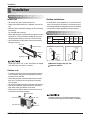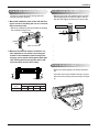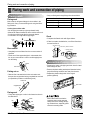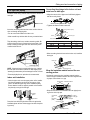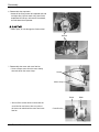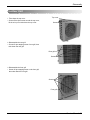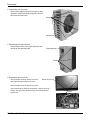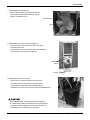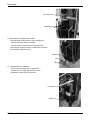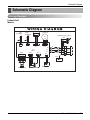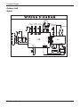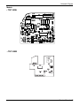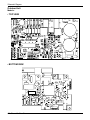
1
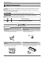
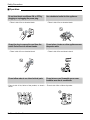
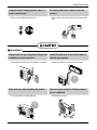
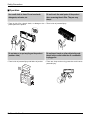
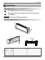
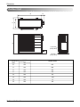
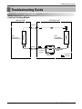
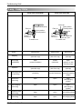
Room Air Conditioner
SERVICE MANUAL
SPLIT TYPE ROOM AIR CONDITIONER
CAUTION
-BEFORE SERVICING THE UNIT, READ THE SAFETY PRECAUTIONS IN THIS MANUAL.
-ONLY FOR AUTHORIZED SERVICE PERSONNEL.
MODEL: GWHD18A1NK3EA
(Applied to new Refrigerant R-410A)
Prior to installation, this air-conditioning unit must
be submitted for approval by the utility service
which provides electricity (EN 61000-3 Norm).
Air Conditioner Service Manual
TABLE OF CONTENTS
Safety Precautions ...........................................................................................................................1
Dimensions .......................................................................................................................................6
Product Specifications ....................................................................................................................8
Installation.........................................................................................................................................9
Flaring work and connection of piping.........................................................................................11
Connecting the cable between indoor unit and outdoor unit.....................................................16
Checking the drainage and forming the pipings .........................................................................18
Air purging ......................................................................................................................................19
Test running ....................................................................................................................................21
Functions.........................................................................................................................................22
Operation.........................................................................................................................................24
Disassembly....................................................................................................................................31
Schematic Diagram ........................................................................................................................38
Troubleshooting Guide ..................................................................................................................42
Safety Precautions
Safety Precautions
To prevent injury to the user or other people and property damage, the following instructions must
be followed.
■ Incorrect operation due to ignoring instruction will cause harm or damage. The seriousness is
classified by the following indications.
This symbol indicates the possibility of death or serious injury.
This symbol indicates the possibility of injury or damage to properties only.
■ Meanings of symbols used in this manual are as shown below.
Be sure not to do.
Be sure to follow the instruction.
■ Installation
Do not use damaged power cords, plugs, or a
loose socket.
• There is risk of fire of electric shock.
Install the panel and the cover of control box
securely.
• There is risk of fire of electric shock.
1 Room Air Conditioner
Always use the power plug and socket with the
ground terminal.
• There is risk of electric shock.
Do not modify or extend the power cord.
• No grounding may cause electric shock.
Safety Precautions
For re-installation of the installed product,
always contact a dealer or an authorized service center.
• There is risk of fire, electric shock, explosion, or
injury.
Be cautious when unpacking and installing the
product.
• Sharp edges could cause injury. Be especially careful of the case edges and the fins on the condenser
and evaporator.
Do not install the product on a defective installation stand.
• It may cause injury, accident, or damage to the
product.
Do not install, remove, or re-install the unit by
yourself.
• There is risk of fire, electric shock, explosion, or
injury.
For installation, always contact the dealer or
an Authorized service center
• There is risk of fire, electric shock, explosion, or injury.
Be sure the installation area does not
deteriorate with age.
• If the base collapses, the air conditioner could fall
with it, causing property damage, product failure,
and personal injury.
Service Manual 2
Safety Precautions
■ Operation
Do not turn the air-conditioner ON or OFF by
plugging or unplugging the power plug.
• There is risk of fire or electrical shock.
Grasp the plug to remove the cord from the
outlet. Do not touch it with wet hands.
• There is risk of fire or electrical shock.
Do not allow water to run into electrical parts.
Use a dedicated outlet for this appliance.
• There is risk of fire or electrical shock.
Do not place a heater or other appliances near
the power cable.
• There is risk of fire and electric shock.
Do not store or use flammable gas or combustibles near the air conditioner.
• There is risk of fire, failure of the product, or electric • There is risk of fire or failure of product.
shock.
3 Room Air Conditioner
Safety Precautions
Unplug the unit if strange sounds, odors, or
smoke comes from it.
• There is risk of electric shock or fire.
Be cautious that water could not enter the
product.
• There is risk of fire, electric shock, or product damage.
■ Installation
Always check for gas (refrigerant) leakage after
installation or repair of product.
• Low refrigerant levels may cause failure of product.
Keep level even when installing the product.
• To avoid vibration or water leakage.
Install the drain hose to ensure that water is
drained away properly.
• A bad connection may cause water leakage.
Use two or more people to lift and transport
the air conditioner.
• Avoid personal injury.
90˚
Service Manual 4
Safety Precautions
■ Operation
Use a soft cloth to clean. Do not use harsh
detergents, solvents, etc.
Do not touch the metal parts of the product
when removing the air filter. They are very
sharp!
• There is risk of fire, electric shock, or damage to the • There is risk of personal injury.
plastic parts of the product.
x
Wa
Do not step on or put anyting on the product.
(outdoor units)
• There is risk of personal injury and failure of product.
5 Room Air Conditioner
Do not insert hands or other objects through
the air inlet or outlet while the air conditioner
is plugged in.
• There are sharp and moving parts that could cause
personal injury.
Dimensions
Dimensions
Symbols Used in this Manual
This symbol alerts you to the risk of electric shock.
This symbol alerts you to hazards that could cause harm to the
air conditioner.
NOTICE This symbol indicates special notes.
Indoor Unit
H
D
W
Installation plate
Model
18k Btu Series
Dimension
W
mm
907
H
mm
285
D
mm
231
Service Manual 6
Dimensions
Outdoor Unit
L2
D
L1
W
H
L3
L5
Liquid side
(2-way valve)
Gas side
(3-way valve)
DIM
MODEL
unit
18k Btu Series
W
mm
845
H
mm
680
D
mm
304
L1
mm
378
L2
mm
68
L3
mm
530
L4
mm
14
L5
mm
100
7 Room Air Conditioner
Product Specifications
Product Specifications
Table-1
Model Name
Item
Unit
MIN
Cooling Capacity
Type
Max
MIN
Heating Capacity Type
Max
Power Input
Running Current
COP
Power Supply
Power Factor
Air Circulation
IN:20°C,Out: -10°C(Heater ON)
IN:20°C,Out: -10°C(Heater OFF)
Cooling
Heating
Heating(-10°C,Heater ON)
Heating(-10°C,Heater OFF)
Cooling
Heating
Heating(-10°C,Heater ON)
Heating(-10°C,Heater OFF)
Cooling
Heating
Indoor,Max
Outdoor,Max
Moisture Removal
Noise Level
Indoor,High
(Sound
Med.
Pressure,1m)
Low
Outdoor,Max
Refrigerant(R410A)Charge
Power Cord
Connecting Cable
Connecting Tube Liquid Side
(Ø. Socket Flare) Gas Side
Length,std
Drain Hose
(O.D , I.D)
Indoor
Dimension
(W*H*D)
Outdoor
Net Weight
Indoor
Outdoor
W
kcal/h.(W)
Btu/h.
W
kcal/h.(W)
Btu/h.
W
kcal/h.(W)
Btu/h.
W
kcal/h.(W)
Btu/h.
W
kcal/h.(W)
Btu/h.
W
kcal/h.(W)
Btu/h.
Btu/h.
Btu/h.
W
W
W
W
A
A
A
A
W/W
W/W
V,Hz
%
m3/min(CFM)
m3/min(CFM)
l/h.(pts/h.)
dB(A)±3
dB(A)±3
dB(A)±3
dB(A)±3
DXL
DXL
mm(in)
mm(in)
m(in)
mm(in)
mm
inch
mm
inch
kg(lbs)
kg(lbs)
GWHD18A1NK3EA
1314
1130
4483
4920
4232
16787
5171
4447
17643
1326
1140
4526
5740
4937
19585
6318
5434
21557
1728
2140
7.53
9.36
2.85
2.68
240/50
98
800
2
47
45
42
57
1600
1.5mm2
1.5mm2
6.35(1/4)
12(1/2)
5(127)
21.5,16.0(0.85,0.63)
907X290X231
35.7X11.4X9.1
840X675X304
33.1X26.6X12.0
13(29)
52(115)
Service Manual 8
Installation
Installation
Selection of the Best Location
Indoor unit
Rooftop Installations:
• Do not have any heat or steam near the unit.
• Select a place where there are no obstacles in front of the
unit.
• Make sure that condensation drainage can be conveniently
routed away.
Do not install near a doorway.
• Ensure that the space around the left and right of the unit is
more than "A". The unit should be installed as high on the
wall as possible, allowing a minimum of "B" from ceiling.
• Use a stud finder to locate studs to prevent unnecessary
damage to the wall.
• If the outdoor unit is installed on a roof structure, be
sure to level the unit. Ensure the roof structure and
anchoring method are adequate for the unit location.
• Consult local codes regarding rooftop mounting.
More than
5cm
More than 10cm
Piping Length and Elevation
Pipe Size
Capacity
(Btu/h)
GAS
LIQUID
18k
1/2"(Ø12.7)
1/4"(Ø6.35)
Max. Additional
Standard Max.
Length Elevation Length Refrigerant
A (m)
(g/m)
(m)
B (m)
5
5
15
Indoor unit
Outdoor unit
A
More than
5cm
B
20
A
Outdoor unit
Indoor unit
B
More than 2.3m
Install the indoor unit on the wall where the height
from the floors more than 2.3 meters.
A
Maximam length of the pipe 15m
B
Hight less than 5m
Outdoor unit
• If an awning is built over the unit to prevent direct sunlight
or rain exposure, make sure that heat radiation from the
condenser is not restricted.
• Ensure that the space around the back and sides is more
than 10cm. The front of the unit should have more than
70cm of space.
• Do not place animals and plants in the path of the warm air.
• Take the air conditioner weight into account and select a
place where noise and vibration are minimum.
• Select a place so that the warm air and noise from the air
conditioner do not disturb neighbors.
More than 60cm
More than 10cm
More than 70cm
9 Room Air Conditioner
More than 10cm
More
than 60cm
• Capacity is based on standard length and maximum allowance length is on the basis of reliability.
Installation
The wall you select should be strong and solid
enough to prevent vibration
Drill a Hole in the Wall
• Drill the piping hole with a ø65mm hole core drill.
Drill the piping hole at either the right or the left
with the hole slightly slanted to the outdoor side.
1. Mount the installation plate on the wall with four
type A screws. If mounting the unit on a concrete
wall, use anchor bolts.
• Mount the installation plate horizontally by aligning
the centerline using a level.
WALL
Indoor
Outdoor
5-7mm
Installation Plate
Chassis
Hook
(3/16"~5/16")
How to Fix Installation Plate
.
•
Type "A" screw
.
2. Measure the wall and mark the centerline. It is
also important to use caution concerning the
location of the installation plate-routing of the
wiring to power outlets is through the walls typically. Drilling the hole through the wall for piping connections must be done safely.
•
.
•
.
•.
Drain hose junction
Installation plate
D
Ø70mm
• Remove the rubber stopple in the desired drain direction.
B
A
C
Left rear piping
CHASSIS
(Grade)
18k
Right rear piping
Ø70mm
• Insert drain hose into the handle of drain pan, and join
drain hose and connecting hose according to the figure
by.
Distance (mm)
A
105
B
65
C
260
D
65
Adhesive
Connecting
part
Drain
hose
Service Manual 10
Flaring work and connection of piping
Flaring work and connection of piping
Flaring work
• Carry out flaring work using flaring tool as shown below.
Flaring work
Main cause for refrigerant leakage is due to defect in the
flaring work. Carry out correct flaring work using the following procedure.
Cut the pipes and the cable.
• Use the piping kit accessory or pipes purchased locally.
• Measure the distance between the indoor and the outdoor unit.
• Cut the pipes a little longer than the measured distance.
• Cut the cable 1.5m longer than the pipe length.
Outside diameter
mm
inch
A
mm
Ø6.35
1/4
0~0.5
Ø12.7
1/2
0~0.5
Check
• Compare the flared work with figure below.
Copper
pipe
90°
Slanted Uneven Rough
• If flare is noted to be defective, cut off the flared section and re-flare it.
Smooth all round
Inside is shiny without scratches
Burr removal
= Improper flaring =
• Completely remove all burrs from the cut cross section of
pipe/tube.
• Put the end of the copper tube/pipe in a downward direction as you remove burrs in order to avoid dropping burrs
into the tubing.
Even length
all round
Inclined Surface Cracked Uneven
damaged
thickness
Connection of piping -- Indoor
Pipe
Reamer
• Preparing the indoor unit's piping and drain hose for installation through the wall.
Point down
• Remove the plastic tubing retainer(see illustration below)
and pull the tubing and drain hose away from chassis.
Putting nut on
• Remove flare nuts attached to indoor and outdoor unit,
then put them on pipe/tube having completed burr removal.
(not possible to put them on after flaring work)
• Replace the plastic tubing holder in the original
position.(Optional)
Flare nut
Drain hose
Copper tube
Flaring work
• Firmly hold copper pipe in a die in the dimension shown in
the table above.
"A"
Bar
Handle
Bar
Yoke
Cone
Copper pipe
Clamp handle
Red arrow mark
11 Room Air Conditioner
When install, make sure that the
remaining parts must be removed
clearly so as not to damage the piping and drain hose, especially power
cord and connecting cable.
Flaring work and connection of piping
Connecting the pipings to the indoor unit and
drain hose to drain pipe.
For right rear piping
Route the indoor tubing and the drain hose in the direction of
rear right.
Drain hose
• Align the center of the pipes and sufficiently tighten
the flare nut by hand.
Indoor unit tubing
Flare nut
Pipes
• Tighten the flare nut with a wrench.
Insert the connecting cable into the indoor unit from the outdoor unit through the piping hole.
Open-end wrench (fixed)
Flare nut
• Do not connect the cable to the indoor unit.
• Make a small loop with the cable for easy connection later.
Wrench
Connection pipe
Indoor unit tubing
Tape the tubing, drain hose, and the connecting cable. Be
sure that the drain hose is located at the lowest side of the
bundle. Locating at the upper side can cause drain pan to
overflow inside the unit.
Outside diameter
mm
inch
Ø6.35
1/4
Ø12.7
1/2
Torque
kg.m
1.8
5.5
• When extending the drain hose at the indoor unit, install the
drain pipe.
Tape
Connecting
pipe
Drain pipe
Drain hose
Connecting cable
NOTE: If the drain hose is routed inside the room, insulate
the hose with an insulation material* so that dripping from
"sweating"(condensation) will not damage furniture or floors.
*Foamed polyethylene or equivalent is recommended.
Indoor unit installation
Indoor unit drain hose
Adhesive
•Overlap the connection pipe insulation material and the
indoor unit pipe insulation material. Bind them together with
vinyl tape so that there is no gap.
• Hook the indoor unit onto the upper portion of the installation plate.(Engage the two hooks of the rear top of the
indoor unit with the upper edge of the installation plate.)
Ensure that the hooks are properly seated on the installation plate by moving it left and right.
Connecting
cable
Vinyl tape(narrow)
Wrap the insulation material around the connecting portion.
Plastic bands Insulation material
• Wrap the area which accommodates the rear piping housing section with vinyl tape.
Indoor
unit pipe
Connection
pipe
Drain hose
Press the lower left and right sides of the unit against the
installation plate until the hooks engage into their slots(clicking sound).
Vinyl tape
Wrap with vinyl tape
(wide)
Connecting cable
Pipe
Vinyl tape(narrow)
Service Manual 12
Flaring work and connection of piping
• Bundle the piping and drain hose together by wrapping
them with vinyl tape for enough to cover where they fit into
the rear piping housing section.
Wrap with vinyl tape
Connecting the pipings to the indoor unit and
the drain hose to drain pipe.
• Align the center of the pipes and sufficiently tighten the
flare nut by hand.
Pipe
Vinyl tape(wide)
Indoor unit tubing
Drain hose
For left rear piping
Flare nut
Pipes
• Tighten the flare nut with a wrench.
Route the indoor tubing and the drain hose to
the required piping hole position.
Open-end wrench (fixed)
Flare nut
Wrench
Connection pipe
Indoor unit tubing
Insert the piping, drain hose, and the connecting cable into the piping hole.
Connecting cable
Outside diameter
mm
inch
Ø6.35
1/4
Ø12.7
1/2
Torque
kg.m
1.8
5.5
Drain pipe
• When extending the drain hose at the indoor unit, install the
drain pipe.
Insert the connecting cable into the indoor unit.
• Don't connect the cable to the indoor unit.
Drain hose
• Make a small loop with the cable for easy connection later.
Tape the drain hose and the connecting cable.
Indoor unit drain hose
• Connecting cable
Adhesive
Vinyl tape (narrow)
Wrap the insulation material around the connecting portion.
• Overlap the connection pipe heat insulation and the indoor
unit pipe heat insulation material. Bind them together with
vinyl tape so that there is no gap.
Indoor unit installation
Plastic bands Insulation material
• Hang the indoor unit from the hooks at the top of the installation plate.
• Insert the spacer etc. between the indoor unit and the
installation plate and separate the bottom of the indoor unit
from the wall.
Indoor unit
Spacer
Installation plate
8cm
13 Room Air Conditioner
Flaring work and connection of piping
• Wrap the area which accommodates the rear piping housing section with vinyl tape.
Indoor
unit piping
Connection
pipe
Vinyl tape
(wide)
Wrap with vinyl tape
Indoor unit installation
• Remove the spacer.
• Ensure that the hooks are properly seated on the installation plate by moving it left and right.
Pipe
Vinyl tape(narrow)
Connecting
cable
Connecting cable
Drain hose
• Bundle the piping and drain hose together by wrapping
them with cloth tape over the range within which they fit
into the rear piping housing section.
Press the lower left and right sides of the unit against the
installation plate until the hooks engage into their
slots(clicking sound).
Pipe
Drain hose
Vinyl tape(narrow)
Wrap with
vinyl tape(wide)
Installation Information (For left piping)
• Good case
For left piping. Follow the instruction below.
• Press on the upper side of clamp. ( )
Reroute the pipings and the drain hose across
the back of the chassis.
• Unfold the tubing to downward slowly. ( )
Piping for
passage through
piping hole
Set the pipings and the drain hose to the back
of the chassis with the tubing holder.
• Hook the edge of tubing holder to tap on chassis and push
the bottom of tubing holder to be engaged at the bottom of
chassis.
• Bend the tubing to the left side of chassis.( C )
Tubing holder
Service Manual 14
Flaring work and connection of piping
Connection of the pipes-Outdoor
• Bad case
• Following bending type from right to left could cause
problem of pipe damage.
Align the center of the pipings and sufficiently
tighten the flare nut by hand.
Finally, tighten the flare nut with torque wrench
until the wrench clicks.
• When tightening the flare nut with torque wrench, ensure
the direction for tightening follows the arrow on the wrench.
Outside diameter
mm
inch
Ø6.35
1/4
Ø12.7
1/2
Torque
kg.m
1.8
5.5
Outdoor unit
Liquid side
piping
(Smaller
diameter)
Gas side piping
(Bigger diameter)
15 Room Air Conditioner
Connecting the cable between indoor unit and outdoor unit
Connecting the cable between indoor unit and outdoor unit
Connect the cable to the Indoor unit.
Connect the cable to the indoor unit by connecting the wires to the terminals on the control board individually
according to the outdoor unit connection. (Ensure that the color of the wires of the outdoor unit and the terminal No.
are the same as those of the indoor unit.)
• The above circuit diagram is subject to change without notice.
• The earth wire should be longer than the common wires.
• When installing, refer to the circuit diagram behind the panel front of the indoor unit.
• Connect the wires firmly so that they may not be pulled out easily.
• Connect the wires according to color codes, referring to the wiring diagram.
Main power source
If a power plug is not used, provide a circuit
breaker between power source and the unit as
shown by.
Air
Conditioner
Circuit Breaker
Use a circuit
breaker or time
delay fuse.
The power cord connected to the indoor unit and the power connecting cable connecting the indoor and outdoor
unit should be selected according to the following specifications (Type "B" approved by HAR or SAA).
(mm2)
Power cord
Connecting cable
1.5
H05W-F
1.5
H07RN-F
Service Manual 16
Connecting the cable between indoor unit and outdoor unit
Outdoor Unit
Connect the cable to the outdoor unit
Remove the control cover from the unit by
loosening the screw.
Terminal block
Connect the wires to the terminals on the control board individually.
Secure the cable onto the control board with
the cord clamp.
Over 5mm
Connecting cable
Cover control
Refix the control cover to the original position
with the screw.
Use a recognized circuit breaker "A"
between the power source and the unit.
A disconnecting device to adequately disconnect all supply lines must be fitted.
This Air-conditioner use 20A.
Blue
Black
Brown YE/GN
Power connection cord
Wire clamp
After the confirmation of the above conditions, prepare the wiring as follows:
1) Never fail to have an individual power circuit specifically for the air conditioner. As for the method of wiring,
be guided by the circuit diagram posted on the inside of control cover.
2) The screw which fasten the wiring in the casing of electrical fittings are liable to come loose from vibrations
to which the unit is subjected during the course of transportation. Check them and make sure that they are
all tightly fastened. (If they are loose, it could cause burn-out of the wires.)
3) Specification of power source.
4) Confirm that electrical capacity is sufficient.
5) See to that the starting voltage is maintained at more than 90 percent of the rated voltage marked on the
name plate.
6) Confirm that the cable thickness is as specified in the power source specification.
(Particularly note the relation between cable length and thickness. (Refer to page 8))
7) Always install an earth leakage switch having operating current not exceeding 30mA in a wet or moist area.
8) The following would be caused by voltage drop.
• Vibration of a magnetic switch, which will damage the contact point, fuse breaking, disturbance of the normal function of the overload.
9) The means for disconnection from a power supply shall be incorporated in the fixed wiring and have an air
gap contact separation of at least 3.5mm in each active(phase) conductors.
17 Room Air Conditioner
Checking the drainage and forming the pipings
Checking the drainage and forming the pipings
Checking the drainage
Form the piping
To remove the front panel from the indoor unit.
• Set the air direction louvers up-and-down to the
position(horizontally) by hand.
Form the piping by wrapping the connecting
portion of the indoor unit with insulation material and secure it with two kinds of vinyl tapes.
• Remove the securing screws that retain the front panel.
Pull the lower left and right sides of the grille toward you
and lift it off.
• If you want to connect an additional drain hose, the end of
the drain outlet should be routed above the ground. Secure
the drain hose appropriately.
In cases where the outdoor unit is installed
below the indoor unit perform the following.
• Tape the piping, drain hose and connecting cable from
down to up.
Pull the right and
the left side.
• Secure the tapped piping along the exterior wall using saddle or equivalent.
Seal small openings
around pipings with a
gum type sealer.
To check the drainage.
• Pour a glass of water on the evaporator.
• Ensure the water flows through the drain hose of the indoor
unit without any leakage and goes out the drain exit.
Taping
Drain
hose
Pipings
Connecting
cable
Trap is required to prevent water
from entering into electrical parts.
In cases where the Outdoor unit is installed
above the Indoor unit perform the following.
• Tape the piping and connecting cable from down to up.
Drain piping
• The drain hose should point downward for easy drain flow.
• Secure the taped piping along the exterior wall. Form a trap
to prevent water entering the room.
• Fix the piping onto the wall by saddle or equivalent.
Downward slope
Seal a small opening
around the pipings
with gum type sealer.
Trap
• Do not make drain piping.
Accumulated
drain water
Air
Do not raise
Water
leakage
Water
leakage
Waving
Tip of drain hose
dipped in water
Water
leakage
Less than
50mm gap
Trap
Ditch
Service Manual 18
Air purging
Air Purging
Air purging
Air and moisture remaining in the refrigerant system have
undesirable effects as indicated below.
• Pressure in the system rises.
• Operating current rises.
• Cooling(or heating) efficiency drops.
• Do a leak test of all joints of the tubing(both indoor and outdoor) and both gas and liquid side service valves.
Bubbles indicate a leak. Be sure to wipe off the soap with a
clean cloth.
• After the system is found to be free of leaks, relieve the
nitrogen pressure by loosening the charge hose connector
at the nitrogen cylinder. When the system pressure is
reduced to normal, disconnect the hose from the cylinder.
• Moisture in the refrigerant circuit may freeze and block capillary tubing.
• Water may lead to corrosion of parts in the refrigeration
system.
Indoor unit
Therefore, the indoor unit and tubing between the indoor and
outdoor unit must be leak tested and evacuated to remove
any noncondensables and moisture from the system.
Air purging with vacuum pump
Preparation
• Check that each tube(both liquid and gas side tubes)
between the indoor and outdoor units have been properly
connected and all wiring for the test run has been completed. Remove the service valve caps from both the gas and
the liquid side on the outdoor unit. Note that both the liquid
and the gas side service valves on the outdoor unit are
kept closed at this stage.
Outdoor unit
Leak test
• Connect the manifold valve(with pressure gauges) and dry
nitrogen gas cylinder to this service port with charge hoses.
Manifold valve
Pressure
gauge
Lo
Hi
Be sure to use a manifold valve for air purging. If it is not
available, use a stop valve for this purpose. The "Hi" knob
of the manifold valve must always be kept close.
• Pressurize the system to no more than 150 P.S.I.G. with
dry nitrogen gas and close the cylinder valve when the
gauge reading reached 150 P.S.I.G. Next, test for leaks
with liquid soap.
To avoid nitrogen entering the refrigerant system in a liquid
state, the top of the cylinder must be higher than its bottom
when you pressurize the system. Usually, the cylinder is
used in a vertical standing position.
19 Room Air Conditioner
Charge hose
Nitrogen gas
cylinder(in vertical
standing position)
Air purging
Soap water method
(1) Remove the caps from the 2-way and 3-way valves.
Gas side
(2) Remove the service-port cap from the 3-way valve.
(3) To open the 2-way valve turn the valve stem counterclockwise approximately 90°, wait for about 2~3 sec, and
close it.
(4) Apply a soap water or a liquid neutral detergent on the
indoor unit connection or outdoor unit connections by a
soft brush to check for leakage of the connecting points
of the piping.
Liquid side
3-way valve
(Close)
2-way valve
(Open)
(5) If bubbles come out, the pipes have leakage.
Evacuation
Hexagonal wrench
• Connect the charge hose end described in the preceding
steps to the vacuum pump to evacuate the tubing and
indoor unit.
Confirm the "Lo" knob of the manifold valve is open. Then,
run the vacuum pump.
The operation time for evacuation varies with tubing length
and capacity of the pump. The following table shows the
time required for evacuation.
Cap
Indoor unit
Required time for evacuation when 30 gal/h vacuum
pump is used
If tubing length is less than 10m (33 ft) if tubing length is longer than 10m (33 ft)
10 min. or more
15 min. or more
Outdoor unit
• When the desired vacuum is reached, close the "Lo" knob
of the manifold valve and stop the vacuum pump.
Finishing the job
• With a service valve wrench, turn the valve stem of liquid
side valve counter-clockwise to fully open the valve.
• Turn the valve stem of gas side valve counter-clockwise to
fully open the valve.
• Loosen the charge hose connected to the gas side service
port slightly to release the pressure, then remove the hose.
• Replace the flare nut and its bonnet on the gas side service
port and fasten the flare nut securely with an adjustable
wrench. This process is very important to prevent leakage
from the system.
Manifold valve
Pressure
gauge
Lo
Lo
Hi
Hi
Open
Close
• Replace the valve caps at both gas and liquid side service
valves and fasten them tight.
This completes air purging with a vacuum pump.
The air conditioner is now ready to test run.
Vacuum pump
Service Manual 20
Test running
Test Running
1. Check that all tubing and wiring have been properly connected.
2. Check that the gas and liquid side service valves are fully
open.
NOTE: If the actual pressure is higher than shown, the system is
most likely over-charged, and charge should be removed.
If the actual pressure are lower than shown, the system is
most likely undercharged, and charge should be added.
The air conditioner is now ready for use.
Settlement of outdoor unit
• Anchor the outdoor unit with a bolt and nut(ø10mm) tightly
and horizontally on a concrete or rigid mount.
• When installing on the wall, roof or rooftop, anchor the
mounting base securely with a nail or wire assuming the
influence of wind and earthquake.
• In the case when the vibration of the unit is conveyed to the
hose, secure the unit with an anti-vibration bushing.
Bolt
PUMP DOWN
This is performed when the unit is to be relocated or
the refrigerant circuit is serviced.
Pump Down means collecting all refrigerant in the outdoor
unit without loss in refrigerant gas.
CAUTION:
Be sure to perform Pump Down procedure with the unit
cooling mode.
Pump Down Procedure
1. Connect a low-pressure gauge manifold hose to the
charge port on the gas side service valve.
2. Open the gas side service valve halfway and purge the air
from the manifold hose using the refrigerant gas.
3. Close the liquid side service valve(all the way in).
Tubing connection
Evaluation of the performance
Operate unit for 15~20 minutes, then check the system
refrigerant charge:
1. Measure the pressure of the gas side service valve.
2. Measure the temperature of the intake and discharge of air.
3. Ensure the difference between the intake temperature and
the discharge is more than 8°C(46°F) (Cooling) or
(Heating).
Intake temperature
4. Turn on the unit's operating switch and start the cooling
operation.
5. When the low-pressure gauge reading becomes 1 to
0.5kg/cm2 G(14.2 to 7.1 P.S.I.G.), fully close the gas side
valve stem and then quickly turn off the unit. At that time,
Pump Down has been completed and all refrigerant gas
will have been collected in the outdoor unit.
Power-Failure Compensation Function User Selection ON/OFF
Operation Sequence
Press the forced switch until BUZZER sounds 1 times
(beep~beep~).
Release the forced switch if BUZZER sounds.
Check the function selection ON/OFF with the operation LED.
Discharge air
Discharge
temperature
4. For reference; the gas side pressure of optimum condition
is as below.(Cooling)
Refrigerant
Outside ambient
TEMP.
R-410A
35°C (95°F)
The pressure of the gas side
service valve.
8.5~9.5kg/cm2G(120~135 P.S.I.G.)
21 Room Air Conditioner
Functions
Functions
Indoor Unit
Cooling Mode Operation
Healty dehumidification Mode Operation
Heating Mode Operation
Operation ON/OFF by Remote controller
Sensing the Room Temperature
Room temperature control
• Maintain the room temperature in accordance with the Setting Temp.
Time Delay Safety Control
• Restarting is for approx. 3 minutes.
Indoor Fan Speed Control
• Super High, High, Med, Low
Operation indication Lamps (LED)
Sleep Mode Auto Control
• The fan is switched to low(Cooling), low(Heating) speed.
• The unit will be stopped after 1, 2, 3, 4, 5, 6, 7 hours.
Natural Air Control by CHAOS Logic
• The fan is switched to intermittent or irregular operation
• The fan speed is automatically switched from high to low speed.
Airflow Direction Control
• The louver can be set at the desired position or swing up and down automatically.
Auto Changeover
Defrost(Deice) Control (Heating)
• Both the indoor and outdoor fan stops during defrosting.
Hot-start Control (Heating)
• The indoor fan stops until the evaporator pipe temperature will be reached at 34°C.
Service Manual 22
Functions
Outdoor Unit
Power Relay Control
• If power is on, it will operate to chage capacitor on controller and power relay will operate after about 2~5sec.
Active Power Filter Control(PSC)
• The active power filter is designed to correct power factor(cos θ) and to regulate DC link voltage.
• It will be operated PFC circuit when the compressor freq. is over 30Hz and wattage is over 450 watt.
Comp. Freq. Control
• The final operating freq. of comp. is set the lowest freq. that limited outdoor temp., discharge pipe temp.,
heat-sink temp., target freq., owing to CT.
OverheatIng. Protection(Power Module)
• When the temp. of power module increases to 85°C, controller decreases Freq. of Comp.
Freq. Speed Control(Up/Down Speed)
• It will be changed the drive freq. of comp. according to temp. of indoor and outdoor.
Total Current Control (Over Current Protection)
DC Peak Current Control
4 way Valve Control
• It is only operated in the heating operation mode except defrosting operation.
Outdoor Fan Motor Control
• High speed
- Although fan motor speed is middle, it will change high speed in case of below AC193V, over 45°C of
outdoor temp., and over fc, fh of comp. Freq.
• Low speed
- Although fan motor speed is middle, it will change Low speed in case of over AC 270V, over 21°C
(Heating Mode) of outdoor temp. below 24°C (Cooling Mode) of outdoor temp.
Discharge Pipe Temp. Control
Low Ambient
Comp. Torque Control
Over Heating Protection (Comp.)
Service Manual 23
Operation
Operation
Function of Controls
• DISPLAY
1) C/O Model
Operation Indicator
• ON while in appliance operation, OFF while in appliance pause.
• Flashing while in disconnection or short in Thermistor. (3 sec off / 0.5 sec on)
Timer Indicator
• ON while in timer mode (on/off), OFF when timer mode is completed or canceled.
Comp. Running Incidator
• While in appliance operation, ON while in outdoor unit compressor running, OFF while in compressor off.
2) H/P Model
Operation Indicator
• ON while in appliance operation, OFF while in appliance pause.
• Flashing while in disconnection or short in Thermistor. (3 sec off / 0.5 sec on)
Timer Indicator
• ON while in timer mode (on/off), OFF when timer mode is completed or canceled.
Defrost Indicator
• OFF except when hot start during heating mode operation or while in defrost control.
Protection of the evaporator pipe from frosting
• If the indoor pipe temperaure is below -1°C in 3 min. after the compressor operates without pause while in
cooling cycle operation mode,
➔ compressor, outdoor fan are turned off.
• When indoor pipe temp. is 10°C or higher after 3 min pause of compressor
Room Air Conditioner 24
Operation
Cooling mode operation
• Operating frequency of compressor depend on the difference of the temperature.
(= intake air Temp.- Compressor off Temp.
• Compressor off temp.= setting temp. -0.5°C
on temp. = setting temp. +0.5°C
• Condition of compressor turned off
- When intake air temperature stay at the temperature between setting temp. -0.5°C and setting temp.
-1.0°C for 3 minutes continuously.
- When intake air temperature reaches below the temperature of setting temp. -1.0°C.
• Compressor 3 minutes delay
- The compressor can restart minimum 3 minutes later after compressor off.
25 Service Manual
Operation
Heating mode operation
• Operating frequency of compressor depend on the difference of the temperature
(= compressor off temp. - intake air temp.)
• Compressor off temp. = setting temp.+3.0°C
on temp. = setting temp.
• Condition of compressor turned off
- When intake air temperature reaches +3°C above the setting temperature.
• Condition of indoor fan turned off
- While in compressor on:indoor pipe temp. < 30°C
• While in defrost control, between the indoor and outdoor fans are turned off.
• Compressor 3 minutes delay
- After compressor off, the compressor can restart minimum 3 minutes later.
Room Air Conditioner 26
Operation
Sleep timer operation
• When the sleep time is reached after [1,2,3,4,5,6,7hr] is input by the remote control during the operation, the
operation of the appliance stops.
• When the appliance is on pause, the sleep timer mode cannot be input.
1. Sleep timer operation for cooling cycle
• While in cooling mode operation, 60 min. later since the start of the sleep timer, the setting temperature
increase by 1°C. After another 30min. elapse, it increases by 1°C again.
Setting temp. (˚C)
1.0˚C up
1.0˚C up
Cooling ON temp.
(Setting temp. +0.5˚C)
Cooling OFF temp.
(Setting temp. -0.5˚C)
0.5
1
Sleep time (hr)
2. Sleep timer operation for heating cycle
• While in heating mode operation, 60 min. later since the start of the sleep timer, the setting temperature
decrease by 1°C. After another 60min. elapse, it decreases by 1°C again.
Setting temp. (°C)
Heating ON temp.
(Setting temp)
1.0°C down
1.0°C down
Heating OFF temp.
(Setting temp. +3.0°C)
1
27 Service Manual
2
Sleep time (hr)
Operation
Auto restarting operation
• When the power is restarted after a sudden power failure while in appliance operation, the mode before the
power failure is kept on the memory and the appliance automatically operates in the mode on the memory.
• Operation mode that is kept on the memory
- State of operation ON/OFF
- Operation mode/setting temp./selected airflow speed
- Sleep timer mode/remaining time of sleep timer
- Chaos Swing
Forced operation
• To operate the appliance by force in case that the remote control is lost, the forced operation selection switch
is on the main unit of the appliance to operate the appliance in the standard conditions.
• The operation condition is set according to the outdoor temp. and intake air temperature as follows.
Indoor temp.
Operating Mode
Setting temp.
over 24°C
Cooling
25°C
21~24°C
FAN
below 21°C
Heating
Setting speed of
indoor fan
High speed
18°C
❈ The unit select before operating mode in 3 hours.
Protection from total current control
■ CT1 control
• If the operating current reaches 13A, the operating frequency of the compressor stop insteally.
• After stoping 3min, the compressor will operate again.
■ CT2 control
• If the operating current of the appliance reaches I2A, the compressor will keep the frequence.
• If the operating current of the appliance reaches 12.5A, the compressor's frequence will dearease, until
the current less than 12A.
Protection from DC Peak Current
■ DC Peak Current Error by a fault signal of IPM
• If the operating current of IPM reaches 27A, the compressor stop instantly.
• If DC PEAK occurs 5 times within 1 hour, the appliance turns off and display ERROR CODE H5
.
■ DC Peak Current Error by the compressor lock
• If the DC LINK voltage below DC 140V occurs 5 times within 1 hour while the compressor is operating, the
appliance turns off and display ERROR CODE H5.
■ DC Peak Current Error by the Outdoor Fan Lock
• If it’s 5 times within 1 hour in case of the temperature of outdoor pipe TH is over 65°C while the compressor is
operating, the appliance turns off and display ERROR CODE E4.
Room Air Conditioner 28
Operation
Portection from overheating of power module
• If the temperature of the heat sink TH. reaches over Toff, the Compressor stop instantly.
• It will be limited the compressor operating frequency according to the heat sink TH.(refer to below FIG.)
• It will be blink 4 times, when the thermistor is open or short, also the temperature is over Toff.
120 °C
∆T = (T off - T on)
T1 = T on + ∆T
T2 = T on + 2 * ∆T
Heat Sink Temp.
T2 °C
T1 °C
T on °C
Compress Frequency
Protection from overheating of compressor
• If the temperature of the discharge pipe of compressor reaches over 130°C or below -30°C the compressor
stop instantly.
• It will be limited the compressor operating frequency according to the compressor dome TH.(Refer to below
Fig.)
• Temperature range by COMP SPEC varies by 10°C.
D-Pipe Temp.
110°C
T3 °C
T2 °C
T1 °C
-13 °C
Compress Frequency
29 Service Manual
∆T = (T off - T2)/2
T1 = T2 - 2 * ∆T
T3 = T2 + ∆T
Operation
Remote Control Operations
The remote control sends signals to the appliance.
1.
Liquid crystal display
Displays all the operating modes.
2.
MODE button
Used to select the operating mode.
3.
FAN button
Used to set the fan speed, in sequence, to automatic,
low, medium, high.
4.
SLEEP button
Used to set or cancel SLEEP mode.
5.
SWING button
Used to start or stop the movement of the vertical
louvers.
6.
TIMER ON button
When the appliance is off, this button is used to
switch the air-conditioner on automatically.
Signal transmitter
1
3
2
4
5
6
8
7
9
10
7-8. ROOM TEMPERATURE SETTING buttons
Used to set the room temperature.
9.
Meaning of the symbols shown on the liquid
crystal display:
10.
Automatic fan speed
Low fan speed
Medium fan speed
High fan speed
Cooling indicator
Dehumidification indicator
Fan only operation indicator
Heating indicator
Automatic mode indicator
SLEEP indicator
TIMER OFF button
When the appliance is on, this button is used to
switch the air-conditioner off automatically.
button
Used to switch appliance on or off.
Louver swing indicator
Room Air Conditioner 30
Disassembly
Disassembly
Indoor Unit
Disconnect the unit from power supply before making any checks.
Be sure the power switch is set to “OFF”.
1.Disassemble the front panel
• Open the front panel, loosen the clasp which fix on the front panel,
then lift it up can disassemble the front panel.
2.Disassemble the filter and electric box cover
• Push up the filter, to loosen the clasp, then two filters
could be taken out.
• Screw off the screws which fix on the top cover of
electric box, to open the electric box cover, loosen
the screw on the top cover which fix the manual
switch, then disassemble the electric box cover.
Filter
Electric box cover
Manual switch
31 Service Manual
Disassembly
3. Disassemble the guide louver and body case
• To bend the guide louver, to make the rotating
shaft slide from the groove, then can take
down the guide louver.
• Open 3pcs screw cover, and screw off 6pcs
screw which fix the body case, then lift it up
loosen the clasp, then can take down the
body case.
Screw cover
Screw
Tube sensor
Earth screw
4. Disassemble the electric box
• Screw off 2pcs screw which fix the light board, then disassemble
the light board.
Disassemble the motor terminal, screw off the earth Fixing screw
screw and screw of fixing the electric box by screw
driver, then loosen the upper clasp of electric box
the electric box could be taken down.
Motor terminal
Light board
Screws
5. Disassemble the water tray
• Loosen the clasp under the water tray, then rotate
the water tray, to make it release from the clasp,
then disassemble the water tray.
Room Air Conditioner 32
Disassembly
6. Disassemble the evaporator
• Screw off the fixing screws of evaporator left side
and right side (2 pcs for each side), then lift the
evaporator left side up, and remove it backward,
can take down the evaporator.
• When repair, do not damage the Caution label.
Screws
7. Disassemble the motor and cross flow fan
• Screw off 4pcs screw from the motor clamp,
then take down the motor clamp.
Screws
Motor clamp
Screw
• Screw off the screws which connect with the
cross flow fan and motor, then can pull out
the motor can take down the motor and cross
flow fan.
33 Service Manual
Cross flow fan
Motor
Disassembly
outdoor Unit
1.Take down the top cover
• Screw off the 6pcs screw around the top cover,
lift the unit up can take down the top cover.
Top cover
Screws
2.Disassemble the rear grill
• Screw off 4pcs tapping screw of rear grill, then
take down the rear grill.
Rear grill
Screws
3.Disassemble the front grill
• Screw off 4pcs tapping screw on the front grill,
then take down the front grill.
Screws
Front grill
Service Manual 34
Disassembly
4. Disassemble the front panel
• Screw off the tapping screws of front panel, motor
supporter, chassis condenser side plate, then can
take down the front panel.
Screws
Earth screw
5.Disassemble the right side plate
• Screw off 9pcs screw of the right side plate, then
take down the right side plate.
Right side plate
Screws
6.Disassemble the electric box
• Screw off 2pcs screw of electric box cover,
then take down the electric box cover.
Electric box cover
• Screw off 2pcs screw of electric box cover,
pull out the lead out insert of compressor, reactor, four-way
reactor, four-way valve and fan motor, then take down the
electric box.
35 Room Air Conditioner
Screws
Disassembly
7. Disassemble the axial flow fan
• Srew off the nut which fixing the axial flow fan
by the spanner, then take out the nut, spring
washer, flat washer in turn.
Axial flow fan
Nut
8. Disassemble the motor and motor supporter
• Screw off 4pcs screw which fixing the motor, then
take down the motor.
• Screw off 2pcs screw which fixing the motor supporter,
then can take down the motor supporter.
Screws
Motor
Screws
8. Disassemble the four-way valve
• Screw off the nut which fixing the four-way valve
loop, take down the loop, then use the wet gauze
to wrap the four-way valve, and unsolder four pcs
soldered point on the four-way valve, then can disassemble it.
• Before disassembly, please discharge the refrigerant,
the soldering procedure should be as quickly as possible,
and please keep the gauze wet all the time, do not burn
out the lead wire of compressor by the flame.
Service Manual 36
Disassembly
Four-way valve
Soldered point
9. Disassemble the capillaries and valves
• Unsolder each soldered point of main capillary and
auxiliary, then take down the capillary.
• To screw off the screws which fixing the gas valve
and liquid valve (2pcs for each), unsolder the connection
pipe and take down the valves.
Capillary
Bolt
Valves
10. Disassemble the compressor
• Loosen the 3pcs bottom nut of compressor,
unsolder the air in pipe, and carefully remove
the pipelines, take out the compressor.
Compressor
Bottom nut
37 Room Air Conditioner
Schematic Diagram
Schematic Diagram
Wiring Diagram
Indoor Unit
Models:
ROOM
TEM.SENSOR
DISPLAY
FAN MOTOR
POWER:220/230/240V~50/60HZ
M1
牟
牟
RT2
RT1
ROOM
TUBE
RX
FAN
N1
X111
AP1
SWING
YEGN
BN
BL
AC-L
TR-IN
TR-OUT
XT
BL
N(1)
BK
2
BN
3
X100
L
N
BL
BK
BN
YEGN
TO OUTDOOR UNIT
TUBE
TEM.SENSOR
YEGN
PTC(FUT)
M2
j
k
SWING
MOTOR
i
E
evaporator
X303
MICRO SWITCH
TRANSFORMER
Room Air Conditioner 38
Schematic Diagram
Outdoor Unit
Models:
FAN MOTOR
M4
E
YEGN
E COMPRESSOR
OUTTUBE
OUTROOM
EXHAUST
TEM.SENSOR TEM.SENSOR TEM.SENSOR
YEGN
E
RT1
E
YEGN
BN BN BL YE BK WH
TO INDOOR UNIT
YEGN
BK
BN
BL
XT
BN
OR
RT4
2 4
BL
BN
V
X107
U
X2
X5
RLY1
NO COM LAC
X110
L
BL
BN
-
+
C2
4V
W
WH OR OR BK WH
BK BK
+
39 Service Manual
RD
V
N1 L1 L2
P1 P2
(4-V)
X202 X114
BL
IPM
X1
X13
COM-A
X
YE
CN10
PCB
X106
COMPRESSOR
EXHAUST
FILTERE
1 3
U
M3
X204 X203 AC-L
OUTTUBE OUTROOM
2
3
RT3
X108
E
BL N(1)
RT2
X1
6 4
5 1 3
BN
BN YE BK WH
C1
TEM.SENSOR
+
AC
AC
U1
-
Schematic Diagram
Models:
• TOP VIEW
• TOP VIEW
Service Manual 40
Schematic Diagram
Outdoor Unit
Models:
• TOP VIEW
• BOTTOM VIEW
41 Room Air Conditioner
Troubleshooting Guide
Troubleshooting Guide
Refrigeration Cycle Diagram
Cooling & Heating Models
INDOOR UNIT
OUTDOOR UNIT
LIQUID SIDE
EER
3-WAY VALVE
HEAT
EXCHANGE
(EVAPORATOR)
HEAT
EXCHANGE
(CONDENSER)
GAS SIDE
3-WAY VALVE
REVERSING
VALVE
ACCUMU
LATOR
COMPRESSOR
COOLING
HEATING
Room Air Conditioner 42
Troubleshooting Guide
2-way, 3-way Valve
2-way Valve (Liquid Side)
Hexagonal wrench (4mm)
Flare nut
3-way Valve (Gas Side)
Valve cap
Open position
Flare nut
Closed position
Open position
Closed position
To
piping
connection
To
piping
connection
To outdoor unit
Works
Shipping
1.
Air purging
(Installation)
Operation
Pin
Service Service
port cap port
To outdoor unit
Shaft position
Shaft position
Service port
Closed
(with valve cap)
Closed
(with valve cap)
Closed
(with cap)
Open
(counter-clockwise)
Closed
(clockwise)
Open
(push-pin or with
vacumm pump)
Open
(with valve cap)
Open
(with valve cap)
Closed
(with cap)
Closed
(clockwise)
Open
Open
(counter-clockwise) (connected manifold
gauge)
2.
Pumping down
(Transfering)
Open
Open
3.
Evacuation
(Servicing)
Open
(with charging
cylinder)
Open
Open
4.
Gas charging
(Servicing)
Open
(with charging
cylinder)
5.
Pressure check
(Servicing)
Open
Open
Open
(with charging cylinder)
6.
Gas releasing
(Servicing)
Open
Open
Open
(with charging cylinder)
43 Room Air Conditioner
Troubleshooting Guide
Air purging
The air in the indoor unit and in the piping must be
purged. If air remains in the refrigeration pipes, it will
affect the compressor, reduce to cooling capacity,
and could lead to a malfunction.
Required tools : hexagonal wrench, adjustable wrench,
torque wrenches, wrench to hold the
joints, and gas leak detector.
The additional gas for air purging has been charged
in the outdoor unit.
However, if the flare connections have not be done
correctly and there gas leaks, a gas cylinder and the
charge set will be needed.
Indoor unit
Liquid side
Open
Outdoor unit
2-way
valve
Gas side
Clsed
3-way
valve
Service port nut:
Be sure, using a torque wrench to tighten the service port nut (after using the service port), so that it prevents the
gas leakage from the refrigeration cycle.
CAUTION: Do not leak the gas in the air during Air purging.
• Procedure
(6) Set the 3-way valve to the back seat.
(1) Recheck the piping connections.
(2) Open the valve stem of the 2-way valve counterclockwise approximately 90°, wait 10 seconds, and then set it to closed position.
– Be sure to use a hexagonal wrench to operate
the valve stem.
(3) Check for gas leakage.
– Check the flare connections for gas leakage.
(4) Purge the air from the system.
– Set the 2-way valve to the open position and
remove the cap from the 3-way valve’s service
port.
– Using the hexagonal wrench to press the valve
core pin, discharge for three seconds and then
wait for one minute. Repeat this three times.
(5) Use torque wrench to tighten the service port
nut to a torque of 1.8kg.cm.
(7) Mount the valve stem nuts to the 2-way and 3way valves.
(8) Check for gas leakage.
– At this time, especially check for gas leakage
from the 2-way and 3-way valve’s stem nuts,
and from the service port nut.
CAUTION: If gas leakage are discovered
in step (3) above, take the following
mesures :
If the gas leaks stop when the piping connections
are tightened further, continue working from step (4).
If the gas leaks do not stop when the connections
are retightened, repair the location of the leak, discharge all of the gas through the service port, and
then recharge with the specified amount of gas from
a gas cylinder.
Service Manual 44
Troubleshooting Guide
Pumping Down
Liquid side
Indoor unit
2-Way
valve
Open
Outdoor unit
Gas side
Closed
3-Way
valve
Lo
CLOSE
CLOSE
Purge the air
• Procedure
(1) Confirm that both the 2-way and 3-way valves
are set to the open position.
– Remove the valve stem caps and confirm that
the valve stems are in the raised position.
– Be sure to use a hexagonal wrench to operate
the valve stems.
(6) Operate the air conditioner at the cooling
cycle and stop it when the gauge indicates
1kg/cm2g.
(7) Immediately set the 3-way valve to the closed
position.
– Do this quickly so that the gauge ends up indicating 3 to 5kg/cm2g.
(2) Operate the unit for 10 to 15 minutes.
(3) Stop operation and wait for 3 minutes, then
connect the charge set to the service port of
the 3-way valve.
– Connect the charge hose with the push pin to
the service port.
(4) Air purging of the charge hose.
– Open the low-pressure valve on the charge set
slightly to air purge from the charge hose.
(5) Set the 2-way valve to the closed position.
45 Room Air Conditioner
(8) Disconnect the charge set, and mount the 2way and 3-way valve’s stem nuts and the service port nut.
– Use torque wrench to tighten the service port
nut to a torque of 1.8 kg.m.
– Be sure to check for gas leakage.
Troubleshooting Guide
Re-air Purging
(Re-installation)
Liquid side
Indoor unit
3-Way
valve
Closed
Outdoor unit
Gas side
Closed
3-Way
valve
Gas cylinder
Lo
R410A
OPEN
CLOSE
• Procedure
(1) Confirm that both the liquid side valve and the
gas side valve are set to the closed position.
(2) Connect the charge set and a gas cylinder to
the service port of the Gas side valve.
– Leave the valve on the gas cylinder closed.
(3) Air purging.
– Open the valves on the gas cylinder and the
charge set. Purge the air by loosening the flare
nut on the liquid side valve approximately 45°
for 3 seconds then closing it for 1 minute;
repeat 3 times.
– After purging the air, use a torque wrench to
tighten the flare nut on liquid side valve.
(6) Disconnect the charge set and the gas cylinder, and set the Liquid side and Gas side
valves to the open position.
– Be sure to use a hexagonal wrench to operate
the valve stems.
(7) Mount the valve stem nuts and the service
port nut.
– Use torque wrench to tighten the service port
nut to a torque of 1.8 kg.m.
– Be sure to check for gas leakage.
CAUTION: Do not leak the gas in the air
during Air Purging.
(4) Check for gas leakage.
– Check the flare connections for gas leakage.
(5) Discharge the refrigerant.
– Close the valve on the gas cylinder and discharge the refrigerant until the gauge indicates
3 to 5 kg/cm2g.
Service Manual 46
Troubleshooting Guide
Balance Refrigerant of the 3-way Valve
(Gas leakage)
Liquid side
Indoor unit
Outdoor unit
3-Way
valve
Open
Gas side
3-Way
valve
Open
Lo
OPEN
CLOSE
• Procedure
(1) Confirm that both the 2-way and 3-way valves
are set to the back seat.
(2) Connect the charge set to the 3-way valve’s
port.
– Leave the valve on the charge set closed.
– Connect the charge hose to the service port.
47 Room Air Conditioner
(3) Open the valve (Lo side) on the charge set and
discharge the refrigerant until the gauge indicates 0 kg/cm2G.
– If there is no air in the refrigerant cycle (the
pressure when the air conditioner is not running
is higher than 1 kg/cm2G), discharge the refrigerant until the gauge indicates 0.5 to 1
kg/cm2G. if this is the case, it will not be necessary to apply a evacuatin.
– Discharge the refrigerant gradually; if it is discharged too suddenly, the refrigeration oil will
also be discharged.
Troubleshooting Guide
Evacuation
(All amount of refrigerant leaked)
Liquid side
Indoor unit
Outdoor unit
3-Way
valve
Open
Gas side
3-Way
valve
Open
Vacuum pump
Lo
OPEN
CLOSE
• Procedure
(1) Connect the vacuum pump to the center hose
of charge set center hose
(2) Evacuation for approximately one hour.
– Confirm that the gauge needle has moved
toward -76 cmHg (vacuum of 4 mmHg or less).
(3) Close the valve (Lo side) on the charge set,
turn off the vacuum pump, and confirm that
the gauge needle does not move (approximately 5 minutes after turning off the vacuum
pump).
(4) Disconnect the charge hose from the vacuum
pump.
– Vacuum pump oil.
If the vacuum pump oil becomes dirty or
depleted, replenish as needed.
Service Manual 48
Troubleshooting Guide
Gas Charging
(After Evacuation)
Liquid side
Indoor unit
3-Way
valve
Open
Outdoor unit
Gas side
Open
3-Way
valve
Check valve
Charging
cylinder
Lo
(1)
OPEN
CLOSE
• Procedure
\
(1) Connect the charge hose to the charging
cylinder.
– Connect the charge hose which you dis-connected from the vacuum pump to the valve at
the bottom of the cylinder.
– If you are using a gas cylinder, also use a
scale and reverse the cylinder so that the system can be charged with liquid.
(2) Purge the air from the charge hose.
– Open the valve at the bottom of the cylinder
and press the check valve on the charge set to
purge the air. (Be careful of the liquid refrigerant). The procedure is the same if using a gas
cylinder.
(3) Open the valve (Lo side on the charge set and
charge the system with liquid refrigerant.
– If the system can not be charged with the specified amount of refrigerant, it can be charged
with a little at a time (approximately 150g each
time) while operating the air conditioner in the
cooling cycle; however, one time is not sufficient, wait approximately 1 minute and then
repeat the procedure (pumping down-pin).
49 Room Air Conditioner
This is different from previous procedures.
Because you are charging with liquid refrigerant
from the gas side, absolutely do not attempt to
charge with larger amounts of liquid refrigerant
while operating the air conditioner.
(4) Immediately disconnect the charge hose from
the 3-way valve’s service port.
– Stopping partway will allow the gas to be discharged.
– If the system has been charged with liquid
refrigerant while operating the air conditioner
turn off the air conditioner before disconnecting
the hose.
(5) Mount the valve stem nuts and the service
port nut.
– Use torque wrench to tighten the service port
nut to a torque of 1.8 kg.m.
– Be sure to check for gas leakage.
Troubleshooting Guide
Cycle Parts
Trouble analysis
Breaker tripped or fuse
burnt out
When set the breaker to ON, it will
trip off at once.
Test the insulative resistance for
earthing, to confirm whether unit
is current leakage or not
When turn on the unit, the breaker
will trip in a few minutes
Check the breaker and test
the resistance.
Check the circuit
Air conditioner can not start up
No power supply
The power plug is not connected
well or poor connected.
Check and insert the plug tightly
Wrong wire connection between the
indoor unit and outdoor unit.
According to the electric diagram to
check the wire and connect correctly
Malfunction of wireless remote control
Check the wireless remote control
Fuse of controller was burnt out
Whether the wire connection between strong
Both indoor unit and
outdoor unit can't
start up
current board and light current board of the contr-
Please fix the connection wire firmly
Is the transformer output wire
connected well, is there voltage output?
Please fix connection wire firmly,
check output voltage
oller is firmed ?
Is the setting temp. suitable?
Adjust the setting temp.
Is COOL(HEAT) load suitable?
To check the pretested COOL(HEAT)load
Malfunction of 4-way valve
Poor COOL(HEAT) operation
Replace the fuse of controller
Malfunction of
refrigerant flow
Replace the 4-way valve
Short of refrigerant volume
Charge the refrigerant
Malfunction of compressor
Replace the compressor
Short of valve gate flow volume
To open the valve gate adequately
Air filter were blocked
Clean the filter
Fan speed was set too slow
To set the fan speed to high or
middle speed
Short of air volume
Outdoor unit installation place is
improper
Outdoor unit should be install in a place with well
ventilation, and should be installed the awning.
Service Manual 50
Troubleshooting Guide
Air circulation
is insufficient
Poor cooling
(heating) effect
When unit is
cooling or heating,
both compressor
and outdoor fan
don't run
Air filters are blocked
Clean the filter
Fan speed was set too slow
Set the fan speed to high or
medium speed
Filters of indoor unit are blocked
Clean the filters regularly
Heat exchanger of outdoor unit is blocked
Clean the dust accumulated on the
surface of the heat exchanger
Leakage occurs between high and low pressure
inside compressor
Replace the compressor
Partial blockage of capillary
Replace the capillary
Leakage of refrigerant
Find out the leakage and charge refrigerant
Blockage in one-way valve of outdoor unit
Replace one-way valve
Abnormal power supply of outdoor unit
Check the circuit according to circuit diagram
Abnormal transformer output
Replace the transformer
Damage of main control board
Replace the main control board
Damage of main control board
When unit is
cooling or heating,
the compressor
runs but outdoor
fan doesn't run
Improper setting of temperature
Adjust the set temperature
Breakage of outdoor fan
Replace the fan motor
Wrong wire connection
Wire according to the circuit diagram
Breakage of outdoor fan motor capacitor
Replace the fan motor capacitor
Malfunction of compressor
When cooling or
heating, outdoor
fan runs, but
compressor
doesn't run.
Replace the main control board
Poor contact of connection between the
main control board and module
Replace the compressor
Re-fasten the connection
Abnormal input of power module
Check if input is 320V. If not, replace the
rectifier
Abnormal output of power module
Replace the power module
51 Room Air Conditioner
Troubleshooting Guide
When cooling or
heating, outdoor
fan runs, but
compressor
doesn't run.
Compressor temperature is too high
Cool the compressor for 30 min before running
Wrong wiring
Wire according to the circuit diagram
Damage of main control board
Replace the main control board
Blockage or breakage of drainage hose
Replace the drainage hose
Wrap of refrigerant pipe connector is not
tight enough
Re-wrap and make it tight
Burn-out or broken wire of indoor fan
motor
Repair or change the fan motor
Wrong wiring
Wire according to the circuit diagram
Circuit break or damage of fan motor
capacitor
Replace the main control board
Water leakage
Fan doesn't run
when FAN mode
is set
Abnormal sound
and vibration
Fan of indoor unit contacts other parts
Adjust fan location
There is foreign substance in indoor unit
Take out the foreign substance
Compressor shakes too much
Adjust support washer of the compressor
and tighten loose bolts
Touch of pipeline of outdoor unit
Separate the touched pipeline
Touch of inner plates
1. Tighten connecting screws
2.Stick shock-absorbing clay between plates
Touch of outdoor unit fan blade with
outer case
Adjust louver position
Abnormal sound inside compressor
Replace compressor
Abnormal electromagnetic sound inside
four-way valve when heating
Short circuit inside electromagnetic
valve. Replace the electromagnetic valve
Service Manual 52
Troubleshooting Guide
Malfunction display
Blink 1 time
Compressor is running
Blink 2 times
High-pressure protection stop of compressor
Blink 3 times
Exhaust protection stop
Blink 4 times
Communication malfunction stoop (including indoor
unit and SIPM)
Blink 5 times
SIPM module protection stop
Blink 6 times
Overcurrent protection stop
Blink 7 times
Cooling overload stop
Blink 8 times
Heating anti-high-temperature stop
Blink 9 times
Cooling antifreezing stop
Blink 10 times
Sensor malfunction stop
Blink 1 time
Communication malfunction of unit A (not receiving
correct data for 3 minutes)
Blink 2 times
Indoor middle sensor malfunction of unit A
Blink 3 times
Indoor outlet sensor malfunction of unit A
Blink 4 times
Indoor inlet sensor malfunction of unit A
Blink 5 times
Indoor environmental sensor malfunction of unit A
Blink 6 times
Communication malfunction signal sent by indoor unit
A
Blink 7 times
Antifreezing protection of unit A
Blink 8 times
Anti-high-temperature protection of unit A
53 Room Air Conditioner
Troubleshooting Guide
Blink 1 time
Communication malfunction of unit B (not
receiving correct data for 3 minutes)
Blink 2 times
Indoor middle sensor malfunction of unit B
Blink 3 times
Indoor outlet sensor malfunction of unit B
Blink 4 times
Indoor inlet sensor malfunction of unit B
Blink 5 times
Indoor environmental sensor malfunction of unit B
Blink 6 times
Communication malfunction signal sent by indoor
unit B
Blink 7 times
Antifreezing protection of unit B
Blink 8 times
Anti-high-temperature protection of unit B
Blink 1 time
Blink 2 times
Discharge protection frequency demultiplication
Overcurrent protection frequency demultiplication
Blink 3 times
Cooling overload frequency demultiplication
Blink 4 times
Heating anti-high-temperature frequency
demultiplication of unit A
Blink 5 times
Heating anti-high-temperature frequency
demultiplication of unit B
Blink 6 times
Defrosting
Blink 1 time
Discharge protection frequency limitation
Blink 2 times
Overcurrent protection frequency limitation
Blink 3 times
Cooling overload frequency limitation
Blink 4 times
Heating anti-high-temperature frequency
limitation of unit A
Service Manual 54
Troubleshooting Guide
Blink 5 times
Blink 6 times
Blink 7 times
Blink 8 times
Heating anti-high-temperature frequency
limitation of unit B
Oil return
Keep 8A-current frequency for 3 minutes
Keep 9A-current frequency for 3 minutes
Blink 1 time
Outdoor environmental sensor malfunction
Blink 2 times
Outdoor tube sensor malfunction
Blink 3 times
Outdoor discharge sensor malfunction
Blink 4 times
Compressor overload sensor malfunction
Blink 5 times
SIPM communication malfunction (not receiving
correct data for 10 seconds)
Blink 1 time
Reset stopping
Blink 2 times
Surge current is too high or 17V voltage is too
low
Blink 3 times
Abnormal low speed
Blink 4 times
Switch failure
Blink 5 times
Overload stop
Blink 6 times
Over heat
Blink 7 times
OH or FIN sensor malfunction
Blink 8 times
Poor speed up
(SIPM Message)
Blink 9 times
55 Room Air Conditioner
Poor communication
Troubleshooting Guide
Blink 10 times
Volts D.C. too low
Blink 11 times
FIN temperature too high
Blink 12 times
Abnormal high speed
Blink 13 times
EEPROM data exception
Blink 14 times
Volts D.C. too high
On
Receiving indoor data
Off
Indoor data received
Service Manual 56
Troubleshooting Guide
Voltage table of 15K sensor resistance value
Value of
Voltage
resistance (V)
*15K
(℃) (KΩ)
Temp.
-20
-19
-18
-17
-16
-15
-14
-13
-12
-11
-10
-9
-8
-7
-6
-5
-4
-3
-2
-1
0
1
2
3
4
5
6
7
8
9
10
11
12
13
14
15
16
17
18
19
20
21
22
23
24
25
26
27
28
29
30
31
147.69
139.298
131.436
124.067
117.158
110.677
104.594
98.8834
93.5199
88.4804
83.7433
79.2888
75.0984
71.1548
67.4422
63.9457
60.6514
57.5465
54.6191
51.858
49.2528
46.7926
44.47
42.2765
40.2043
38.246
36.3946
34.6438
32.9875
31.42
29.9362
28.531
27.2
25.9387
24.7432
23.6097
22.5345
21.5144
20.5463
19.6272
18.7545
17.9254
17.1376
16.3889
15.677
15
14.356
13.7431
13.1598
12.6045
12.0756
11.5718
0.46
0.49
0.51
0.54
0.57
0.6
0.63
0.66
0.69
0.72
0.76
0.8
0.83
0.87
0.91
0.95
0.99
1.03
1.08
1.12
1.17
1.21
1.26
1.31
1.36
1.41
1.46
1.51
1.56
1.62
1.67
1.72
1.78
1.83
1.89
1.94
2
2.05
2.11
2.17
2.22
2.28
2.33
2.39
2.44
2.5
2.55
2.61
2.66
2.72
2.77
2.82
Voltage
(V)
*8.1K
0.26
0.27
0.29
0.31
0.32
0.34
0.36
0.38
0.4
0.42
0.44
0.46
0.49
0.51
0.54
0.56
0.59
0.62
0.65
0.68
0.71
0.74
0.77
0.8
0.84
0.87
0.91
0.95
0.99
1.02
1.06
1.11
1.15
1.19
1.23
1.28
1.32
1.37
1.41
1.46
1.51
1.56
1.6
1.65
1.7
1.75
1.8
1.85
1.91
1.96
2.01
2.06
Value of Voltage
Temp. resistance (V)
*15K
(℃) (KΩ)
32
33
34
35
36
37
38
39
40
41
42
43
44
45
46
47
48
49
50
51
52
53
54
55
56
57
58
59
60
61
62
63
64
65
66
67
68
69
70
71
72
73
74
75
76
77
78
79
80
81
82
83
11.0917
10.6341
10.1979
9.7819
9.3851
9.0066
8.6453
8.3004
7.9711
7.6565
7.3561
7.069
6.7946
6.5323
6.2815
6.0416
5.8121
5.5925
5.3823
5.1804
4.9872
4.8023
4.6252
4.4556
4.2931
4.1374
3.9882
3.8452
3.708
3.5765
3.4503
3.3293
3.2131
3.1016
2.9945
2.8917
2.7929
2.698
2.6069
2.5193
2.435
2.3541
2.2762
2.2013
2.1292
2.0599
1.9932
1.9289
1.8671
1.8076
1.7502
1.6949
2.87
2.93
2.98
3.03
3.08
3.12
3.17
3.22
3.26
3.31
3.35
3.4
3.44
3.48
3.52
3.56
3.6
3.64
3.68
3.72
3.75
3.79
3.82
3.85
3.89
3.92
3.95
3.98
4.01
4.04
4.06
4.09
4.12
4.14
4.17
4.19
4.22
4.24
4.26
4.28
4.3
4.32
4.34
4.36
4.38
4.4
4.41
4.43
4.45
4.46
4.48
4.49
Voltage
(V)
*8.1K
2.11
2.16
2.21
2.26
2.32
2.37
2.42
2.47
2.52
2.57
2.62
2.67
2.72
2.77
2.82
2.86
2.91
2.96
3
3.05
3.09
3.14
3.18
3.23
3.27
3.31
3.35
3.39
3.43
3.47
3.51
3.54
3.58
3.62
3.65
3.68
3.72
3.75
3.78
3.81
3.84
3.87
3.9
3.93
3.96
3.99
4.01
4.04
4.06
4.09
4.11
4.13
Temp.
resistance Value of
(℃) (KΩ)
84
85
86
87
88
89
90
91
92
93
94
95
96
97
98
99
100
101
102
103
104
105
106
107
108
109
110
111
112
113
114
115
116
117
118
119
120
121
122
123
124
125
126
127
128
129
130
131
132
133
134
135
Remark: The above voltage value is the power supply voltage 5V, the divider resistance are 15K and8.1K.
57 Room Air Conditioner
1.6417
1.5904
1.541
1.4933
1.4474
1.403
1.3603
1.3191
1.2793
1.2409
1.2038
1.1681
1.1335
1.1002
1.068
1.0369
1.0068
0.9778
0.9497
0.9225
0.8963
0.871
0.848
0.825
0.802
0.779
0.758
0.737
0.717
0.697
0.678
0.66
0.642
0.625
0.608
0.592
0.577
0.561
0.547
0.532
0.519
0.505
0.492
0.48
0.467
0.456
0.444
0.433
0.422
0.412
0.401
0.391
Voltage
(V)
*15K
Voltage
(V)
*8.1K
4.51
4.52
4.53
4.55
4.56
4.57
4.58
4.6
4.61
4.62
4.63
4.64
4.65
4.66
4.67
4.68
4.69
4.69
4.7
4.71
4.72
4.73
4.73
4.74
4.75
4.75
4.76
4.77
4.77
4.78
4.78
4.79
4.79
4.8
4.81
4.81
4.81
4.82
4.82
4.83
4.83
4.84
4.84
4.85
4.85
4.85
4.86
4.86
4.86
4.87
4.87
4.87
4.16
4.18
4.2
4.22
4.24
4.26
4.28
4.3
4.32
4.34
4.35
4.37
4.39
4.4
4.42
4.43
4.45
4.46
4.48
4.49
4.5
4.51
4.53
4.54
4.55
4.56
4.57
4.58
4.59
4.6
4.61
4.62
4.63
4.64
4.65
4.66
4.67
4.68
4.68
4.69
4.7
4.71
4.71
4.72
4.73
4.73
4.74
4.75
4.75
4.76
4.76
4.77
Troubleshooting Guide
Voltage table of 20K sensor resistance value
Temp.
(℃)
-20
-19
-18
-17
-16
-15
-14
-13
-12
-11
-10
-9
-8
-7
-6
-5
-4
-3
-2
-1
0
1
2
3
4
5
6
7
8
9
10
11
12
13
14
15
16
17
18
19
20
21
22
23
24
25
26
27
28
29
30
31
Value of
resistance
(KΩ)
192
181.4
171.4
162.1
153.3
145
137.2
129.9
123
116.5
110.3
104.6
99.13
94
89.17
84.61
80.31
76.24
72.41
68.79
65.37
62.13
59.08
56.19
53.46
50.87
48.42
46.11
43.92
41.84
39.87
38.01
36.24
34.57
32.98
31.47
30.04
28.68
27.39
26.17
25.01
23.9
22.85
21.85
20.9
20
19.14
18.13
17.55
16.8
16.1
15.43
Voltage(V)
*15K
0.47
0.5
0.52
0.55
0.58
0.61
0.64
0.67
0.7
0.73
0.77
0.8
0.84
0.88
0.92
0.96
1
1.04
1.08
1.13
1.17
1.22
1.26
1.31
1.36
1.41
1.46
1.51
1.56
1.62
1.67
1.72
1.78
1.83
1.89
1.94
2
2.05
2.11
2.17
2.22
2.28
2.33
2.39
2.44
2.5
2.55
2.62
2.66
2.72
2.77
2.82
Temp.
Value of
resistance
(℃)
(KΩ)
32
33
34
35
36
37
38
39
40
41
42
43
44
45
46
47
48
49
50
51
52
53
54
55
56
57
58
59
60
61
62
63
64
65
66
67
68
69
70
71
72
73
74
75
76
77
78
79
80
81
82
83
14.79
14.18
13.59
13.04
12.51
12
11.52
11.06
10.62
10.2
9.803
9.42
9.054
8.705
8.37
8.051
7.745
7.453
7.173
6.905
6.648
6.403
6.167
5.942
5.726
5.519
5.32
5.13
4.948
4.773
4.605
4.443
4.289
4.14
3.998
3.861
3.729
3.603
3.481
3.364
3.252
3.144
3.04
2.94
2.844
2.752
2.663
2.577
2.495
2.415
2.339
2.265
Voltage(V)
*8.1K
2.87
2.93
2.98
3.03
3.08
3.13
3.17
3.22
3.27
3.31
3.36
3.4
3.44
3.48
3.52
3.56
3.6
3.64
3.68
3.72
3.75
3.79
3.82
3.85
3.89
3.92
3.95
3.98
4.01
4.04
4.06
4.09
4.12
4.14
4.17
4.19
4.21
4.24
4.26
4.28
4.3
4.32
4.34
4.36
4.38
4.4
4.41
4.43
4.45
4.46
4.48
4.49
Temp.
(℃)
84
85
86
87
88
89
90
91
92
93
94
95
96
97
98
99
100
101
102
103
104
105
106
107
108
109
110
111
112
113
114
115
116
117
118
119
120
121
122
123
124
125
126
127
128
129
130
131
132
133
134
135
Value of
resistance
(KΩ)
2.194
2.125
2.059
1.996
1.934
1.875
1.818
1.736
1.71
1.658
1.609
1.561
1.515
1.47
1.427
1.386
1.346
1.307
1.269
1.233
1.198
1.164
1.131
1.099
1.069
1.039
1.01
0.9825
0.9556
0.9295
0.9043
0.8799
0.8562
0.8333
0.8111
0.7695
0.7687
0.7455
0.7289
0.7099
0.6915
0.6738
0.6583
0.6395
0.6232
0.6074
0.5921
0.5772
0.5627
0.5487
0.5351
0.5212
Voltage(V)
*8.1K
4.51
4.52
4.53
4.55
4.56
4.57
4.58
4.6
4.61
4.62
4.63
4.64
4.65
4.66
4.67
4.68
4.68
4.69
4.7
4.71
4.72
4.73
4.73
4.74
4.75
4.75
4.76
4.77
4.77
4.78
4.78
4.79
4.79
4.8
4.81
4.81
4.81
4.82
4.82
4.83
4.83
4.84
4.84
4.85
4.85
4.85
4.86
4.86
4.86
4.87
4.87
4.87
Remark: The above voltage value is the power supply voltage 5V, the divider resistance are 20K.
Service Manual 58
Troubleshooting Guide
Voltage table of 50K sensor resistance value
Temp.
(℃)
-20
-19
-18
-17
-16
-15
-14
-13
-12
-11
-10
-9
-8
-7
-6
-5
-4
-3
-2
-1
0
1
2
3
4
5
6
7
8
9
10
11
12
13
14
15
16
17
18
19
20
21
22
23
24
25
26
27
28
29
30
31
(KΩ)
Voltage
(V)
*15K
484.5536
457.3636
431.8647
407.9418
385.4885
364.4061
344.6029
325.9941
308.5007
292.0497
276.573
262.0074
248.2941
235.3787
223.2101
211.741
200.9274
190.7282
181.1052
172.0225
163.447
155.3267
147.6573
140.4114
133.5631
127.0885
120.9652
115.172
109.6896
104.4994
99.5843
94.9283
90.5162
86.3341
82.3687
78.6076
75.0392
71.6526
68.4376
65.3846
62.4845
59.729
57.11
54.6202
52.2524
50
47.8569
45.8171
43.8752
42.0259
40.2644
38.5861
0.04
0.05
0.05
0.05
0.06
0.06
0.06
0.07
0.07
0.07
0.08
0.08
0.09
0.09
0.09
0.1
0.1
0.11
0.12
0.12
0.13
0.13
0.14
0.15
0.16
0.16
0.17
0.18
0.19
0.2
0.21
0.22
0.23
0.24
0.25
0.26
0.27
0.28
0.3
0.31
0.32
0.34
0.35
0.36
0.38
0.4
0.41
0.43
0.45
0.46
0.48
0.5
Value of
resistance
Temp.
Value of
resistance
(℃)
(KΩ)
Voltage
(V)
*8.1K
36.9866
35.4618
34.0079
32.6212
31.2983
30.0359
28.8309
27.6805
26.582
25.5326
24.5301
23.572
22.6562
21.7806
20.9433
20.1424
19.3761
18.6428
17.9409
17.2683
16.6244
16.008
15.4177
14.8522
14.3105
13.7913
13.2937
12.8167
12.3592
11.9204
11.4994
11.0955
10.7078
10.3357
9.9784
9.6352
9.3056
8.9889
8.6846
8.3921
8.111
7.8406
7.5807
7.3306
7.09
6.8585
6.6357
6.4212
6.2147
6.0159
5.8243
5.6398
0.52
0.54
0.56
0.58
0.6
0.63
0.65
0.67
0.7
0.72
0.75
0.77
0.8
0.82
0.85
0.88
0.91
0.94
0.97
1
1.03
1.06
1.09
1.12
1.16
1.19
1.22
1.26
1.29
1.33
1.36
1.4
1.43
1.47
1.51
1.54
1.58
1.62
1.66
1.69
1.73
1.77
1.81
1.85
1.89
1.93
1.97
2.01
2.04
2.08
2.12
2.16
32
33
34
35
36
37
38
39
40
41
42
43
44
45
46
47
48
49
50
51
52
53
54
55
56
57
58
59
60
61
62
63
64
65
66
67
68
69
70
71
72
73
74
75
76
77
78
79
80
81
82
83
Temp.
Value of
resistance
(℃)
(KΩ)
Remark: The above voltage value is the power supply voltage 5V, the divider resistance are 4.3K.
59 Room Air Conditioner
84
85
86
87
88
89
90
91
92
93
94
95
96
97
98
99
100
101
102
103
104
105
106
107
108
109
110
111
112
113
114
115
116
117
118
119
120
121
122
123
124
125
126
127
128
129
130
131
132
133
134
135
5.4621
5.2908
5.1257
4.9665
4.8131
4.6651
4.5224
4.3847
4.2518
4.1236
3.9999
3.8805
3.7652
3.6538
3.5463
3.4424
3.3421
3.2451
3.1513
3.0607
2.9731
2.8884
2.8065
2.7273
2.6507
2.5766
2.5049
2.4355
2.3683
2.3033
2.2403
2.1794
2.1203
2.0632
2.0078
1.9541
1.9021
1.8518
1.8029
1.7556
1.7097
1.6653
1.6221
1.5803
1.5397
1.5003
1.4621
1.4251
1.3891
1.3542
1.3203
1.2874
Voltage
(V)
*8.1K
2.2
2.24
2.28
2.32
2.36
2.4
2.44
2.48
2.51
2.55
2.59
2.63
2.67
2.7
2.74
2.78
2.81
2.85
2.89
2.92
2.96
2.99
3.03
3.06
3.09
3.13
3.16
3.19
3.22
3.26
3.29
3.32
3.35
3.38
3.41
3.44
3.47
3.49
3.52
3.55
3.58
3.6
3.63
3.66
3.68
3.71
3.73
3.76
3.78
3.8
3.83
3.85
UFFICI COMMERCIALE E TECNICO - VIA SEITZ, 47 - 31100 TREVISO -ITALIA,
TELEFONO 0422 4131 - TELEFAX 0422 413659
GRUPPO
P/No.: 3828A20833B
R