1
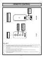
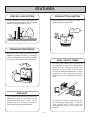
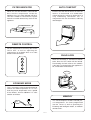
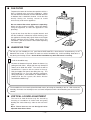
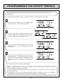
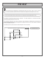
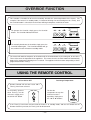
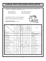
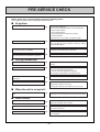
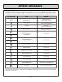
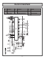
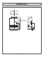
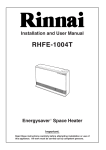
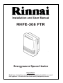
Installation and User Manual
RHFE-308 FTR
Energysaver Space Heater
Important.
Read these instructions carefully before attempting installation or use of
this appliance. All work must be carried out by competent persons.
CONTENTS
Getting to Know your RHFE-308 FTR ………………………………………………………………………3
Remote Control …………………………………………………………………………………………………4
Control Panel Layout …………………………………………………………………………………………5
Features …………………………………………………………………………………………………………6
Safety Points ……………………………………………………………………………………………………8
Operating your new RHFE-308 FTR ………………………………………………………………………10
Setting the Clock ………………………………………………………………………………………………14
Pre-heat ………………………………………………………………………………………………………17
Override Function ……………………………………………………………………………………………18
Caring for your new RHFE-308 FTR ………………………………………………………………………19
Error Messages ………………………………………………………………………………………………21
Installation Instructions ………………………………………………………………………………………22
Location ………………………………………………………………………………………………………24
Installing the Flue ……………………………………………………………………………………………27
Sleeve and Manifold Installation ……………………………………………………………………………29
Flue Extension Kits ……………………………………………………………………………………………32
Conversion ……………………………………………………………………………………………………36
Connecting Gas and Electrical Services ……………………………………………………………………37
Testing …………………………………………………………………………………………………………38
Gas Pressure Setting …………………………………………………………………………………………39
Block and Wiring Diagram ……………………………………………………………………………………42
Dimensions ……………………………………………………………………………………………………44
Specification……………………………………………………………………………………………………46
Service Contact ………………………………………………………………………………………………48
–2–
GETTING TO KNOW YOUR NEW RHFE-308FTR
REMOTE CONTROL
BRACKET
CONTROL PANEL
Concealed panel with
clock, room and preset temperature
selection.
Time, temperature
and appliance error
codes are shown
here.
LOUVRE
Warm air discharge
duct.
HUMIDIFIER TRAY
Built into the warm air
discharge duct.
Humidifies the warm
air flow.
ON/OFF SWITCH
BOTTOM TRIM
Pulls off to allow filling
of humidifier tray.
AIR FILTER
Helps to protect the
interior of the
appliance and fan
from dust particles.
AIR INLET TUBE
Carries air for
combustion.
EXHAUST OUTLET
Exhausts flue products
to the outside of the
building.
GAS CONNECTION
ROOM
TEMPERATURE
SENSOR
FLUE SYSTEM
(Supplied Separately)
ELECTRICAL CORD
Rinnai Corporation - Japan
ISO 9001
APPROVED BY JIA
Manufactured under a
Quality System Certified
as complying with ISO
9001 by an Accredited
Certification Body.
–3–
Power source
for operating
remote control.
REVERSE
R2032
C
OPEN
FRONT
Increases or decreases
the temperature setting.
TEMPERATURE
ADJUSTMENT
Stops heater manually.
OFF
ON
Operates the heater
manually.
ON BUTTON
OFF BUTTON
TO REPLACE BATTERY
Simply open the back of the remote
control and replace Lithium battery.
TYPE: CR 2032
BATTERY
REMOTE CONTROL
■ NOTE
> Some fluorescent lights may interfere with the transmission of remote control signals, in this case
changing the position from which you are operating the remote control may help.
> Avoid leaving the remote control in direct sunlight and do not place the remote close to the louvres
of the heater.
> Avoid getting the remote control wet, or dropping it.
> The remote control works within 5 metres and an angle of 40˚ to the receiver on the heater.
> Only use the battery type specified. (CR 2032).
> Remove battery if control is not going to be used for a long period. This will help to avoid damage
from leaking batteries.
–4–
–5–
Selects energy
saving function.
ECONOMY
Temporarily changes operation
from ON to OFF or OFF to ON,
until next programmed setting
is reached.
OVERRIDE
Selects clock and/or
Timers for adjusting
or programming.
SET TIMES
REMOTE CONTROL
RECEIVER
Main switch for turning
ON/OFF.
Increases or decreases the
temperature setting as well as
changing hours or minutes.
ON / OFF
ON
Filter
Selects operating
mode for Timer 1
or 2.
off
Locks all controls when
pressed.
(EXCEPT OFF)
on
ON/OFF BUTTON
Set times
Timer 2
TIME/TEMP ADJUSTMENT
Temp
・
Time
Set ・ Room
Timer 1
Clock
Indicates that the filter
needs cleaning.
FILTER INDICATOR
ON TIMER
Timer 2 Override
AM
PM
Indicates that clock or dual timer
programme is being set.
CLOCK ADJUSTMENT AND
TIMER INDICATORS
Indicates that the appliance is turned
ON and whether the burner is alight.
POWER ON/COMBUSTION
INDICATOR
CHILD LOCK
Child Lock Economy Timer 1
OVERRIDE
INDICATOR
Shows either the time of
day, temperatures, or
coded error messages.
TIME/TEMP DISPLAY
Indicates that the
override function is
activated.
Indicates that Timer 1
or Timer 2 has been
selected to operate.
TIMER INDICATOR
Indicates that the
Economy mode is in
operation.
ECONOMY
INDICATOR
Indicates Child lock is
activated.
CHILD LOCK
INDICATOR
CONTROL PANEL LAYOUT
FEATURES
FORCED FLUE SYSTEM
PUSH BUTTON IGNITION
Air for combustion is taken from outside the
room and the flue products are exhausted
outside, keeping the room air clean.
Only one touch of the ON/OFF switch is
required to operate the heater.
EXHAUST
ONE
TOUCH
AIR
INLET
WARM AIR DISCHARGE
Warm air flows from the bottom of the
appliance through the louvres, assisting in
even heat distribution. An integral humidifier
tray is built into the warm air discharge duct.
DUAL ON/OFF TIMER
The Dual Timer allows you to programme
the appliance to come on for two separate
periods each day, usually one period in the
morning, and one period in the evening.
The built in Intelligent Mode brings the room
temperature to the temperature you have
selected, by the time programmed into the
Timer.
PRE-HEAT
The function will automatically operate the
appliance within one hour prior to the
programmed time of the Timer. This is
designed to heat a room to the pre-set
temperature by the programmed time.
The Dual Timer feature means that you can
“Set and Forget” your heater. It will turn
itself ON and OFF at times you have
programmed until you cancel the Timer
program.
–6–
FILTER INDICATOR
AUTO COMFORT
When the fan filter becomes covered with
dust and the temperature inside the
appliance rises, the filter indicator will flash.
The filter should be vacuumed at regular
intervals to avoid unnecessary strain on the
appliance.
Ensures that the flow of warm air from the
louvres is maintained at a comfortable
volume during the warm-up period by a 8
step modulating convection fan, in
conjunction with the thermostat, reducing
cool draughts.
FITER INDICATOR
REMOTE CONTROL
For the convenience of turning the heater
ON or OFF, as well as adjusting the
temperature up or down while at a short
distance from the heater.
CHILD LOCK
ON
When the Child lock is activated all controls
other than the OFF switch will be locked.
Deactivating the lock releases the controls.
If the lock is activated when the appliance is
off, all functions will be locked.
OFF
LOCKED
ECONOMY MODE
This is an energy saving feature designed to
reduce the room temperature to 1˚C less
than the pre-set temperature over a period
of 30 minutes, and an additional 1˚C after
another 30 minutes.
MEMORY
£
PRE-SET
TEMP
The micro-computer records selected preset temperatures, the times programmed
into the Timers as well as operating the
Economy and Intelligent modes, to maintain
comfort levels.
2C
1 hour
–7–
SAFETY POINTS
Do not restrict the warm air discharge by
placing articles in front of the heater.
This appliance must not be used for any
purpose other than heating.
Do not spray aerosols whilst the heater is
operating. Most aerosols contain butane gas,
and can be a fire hazard if used near this
heater when it is in use.
Flue guard is recommended where children
may be able to touch the flue terminal.
Do not allow curtains or other flammable or
combustible materials to come into contact
with the heater.
Do not allow anyone to sit on or lean against
the appliance.
Combustible materials must not be placed
where the heater could ignite them.
–8–
SAFETY POINTS
Keep flammable materials, trees, shrubs, etc,
away from the flue terminal.
Do not allow anyone to post articles through
the louvres.
GAS
Gasoline
LPGAS
Filter should be cleaned at regular intervals.
Young children should be supervised at all
times. Hand or body contact with the louvres
should be avoided.
Clean with vacuum cleaner, weekly.
Do not allow young children or the infirm to
sleep directly in front of the heater.
Do not place articles containing liquids on top
of the heater. Liquids spilt on the controls may
cause extensive damage.
–9–
OPERATING YOUR NEW RHFE-308FTR
■ TO OPEN THE CONTROL PANEL
Lift lightly in the centre of the lid where there is
a catch. The control panel lid will then drop
backward to an angle.
LIFT
■ TURNING ON
Press the ON/OFF button to operate the
heater. The ON indicator will glow green.
After approximately 20 seconds the spark
generator will be heard before the burner
ignites and the ON indicator glows red,
indicating that the burner is alight. Warm air
can be felt coming from the louvres 15
seconds later.
Filter
ON
ON / OFF
If the heater does not ignite on initial use, this may be due to air remaining in the gas supply line. The
spark generator will only continue for 15 seconds. After this it will be necessary to press the ON/OFF
button OFF, then ON again.
■ TURNING OFF
Simply press the ON/OFF button to switch off
the heater. The ON indicator will go out. The
convection fan will continue to operate for
several minutes after the burner has gone out
in order to cool the appliance. Do not unplug
the appliance while the convection fan is
running.
Filter
ON
ON / OFF
DO NOT turn heater off by unplugging at the power point.
The convection fan must continue to run until the appliance cools.
– 10 –
■ ROOM TEMPERATURE ADJUSTMENT
The room temperature and pre-set temperatures can only be displayed and adjusted when the heater is
running.
1
Press the “
” button to increase the temperature
setting or “
” button to decrease the temperature
setting.
The Temperatures can be preset to:
a) [ L ] low (about 10˚C)
b) [16˚C] to [26˚C] in 1˚C steps
c) [ H ] (continuously high)
AM
PM
Set ・ Room
Temp
・
Time
If the heater does not ignite then the pre-set temperature may not be set to a setting which is higher
than the room temperature. The ON indicator will change colour from red to green when the heater
reaches the pre-set temperature and stops runnning.
■ ECONOMY MODE
The Economy mode may only be operated when the heater is turned on, but remains in the system
memory once set until deactivated.
Select the Economy mode before selecting time operation.
1
Child Lock Economy Timer 1
Press the Economy button to start the Economy
function. The Economy indicator will glow.
2
Child Lock Economy Timer 1
Press the Economy button once more to switch off
the function.
– 11 –
Preset temperature
After the room is heated initially the air temperature
may be dropped to a lower level without affecting
comfort. 30 mins after the selected room temperature
(set with the thermostat) is reached, the Economy
mode, if set, reduces the temperature by 1˚C. After
another 30 mins it reduces the temperature by a
further 1˚C, this is an energy saving feature. The
Economy mode does not operate if the heater is
under capacity for the room size.
1°reduction
1°reduction
30 min
30 min
■ CHILD LOCK
The Child lock will help to prevent accidental operation as well as small children from altering the
controls.
1
To operate the Child lock simply press the Child Lock
button. The function is activated immediately and the
Child lock indicator will glow.
Child Lock Economy Timer 1
Timer 2 Override
Child Lock Economy Timer 1
Timer 2 Override
2
To deactivate the Child lock simply press the Child
Lock button for 2 seconds and the Child lock indicator
will go out. The lock can be deactivated at any time
in this way.
During normal operation the Child lock may be activated and all controls other than the OFF switch will
be locked. Deactivating the lock releases the controls. If the lock is activated whilst the heater is turned
OFF, then all functions will be locked. If the heater is turned OFF whilst the Child lock is activated, it
cannot be turned ON again until the lock is deactivated.
■ AUTO COMFORT
A room temperature sensor located at the rear of the appliance is continuously monitoring the temperature
of the room. The main purpose of Auto Comfort is to improve control over the flow of warm air being
discharged through the louvres when the heater is first operated. The means by which this control is
achieved is a 7 speed modulating convection fan and the temperature sensor, in conjunction with a microcomputer.
In order to achieve comfortable heating, it is preferable to avoid cold draughts from the appliance. In the
case of a conventional fan heater, the convection fan operates normally from the time of ignition and a
cool draught may accompany the flow of air from the appliance.
To overcome this situation, fuzzy logic controls the speed of the convection fan after taking into
consideration the room temperature at the time of ignition. For example: the room temperature is low,
then the fan rotates at low speed. As the room temperature rises the speed of the convection fan
gradually increases.
In this way it is possible to ensure a comfortable flow of warmed air, as well as decreasing the sensation
of cold draughts immediately after ignition.
The convection fan speed increases proportionally as the room gradually heats up. This improves the
warm air distribution, assisting in a reduction of warm air stratification throughout the room, and resulting
in more effective heating conditions.
The micro computer continuously monitors the room temperature and adjusts the covection fan speed
according to the conditions at the time.
– 12 –
■ FAN FILTER
To protect the room air fan from dust particles or lint, a
filter is situated at the rear of the appliance. When
this filter becomes blocked, the filter indicator will flash
to indicate that it should be cleaned. Clean the filter
weekly during the heating season to avoid
unnecessary strain on the appliance.
Do not remove filter when appliance is operating.
When the filter requires cleaning, clean filter before
using the appliance, or whilst the appliance is not
operating.
If you do not clean the filter at regular intervals and
the filter indicator is allowed to remain flashing, then
the appliance will stop and [14] will flash on the Digital
Display signifying that the inbuilt safety device has
functioned. You must clean the filter before operating
the heater again.
■ HUMIDIFIER TRAY
So that you can humidify the air, your Rinnai RHFE-308FTR is fitted with an enamelled tray at the
bottom of the heater. If you choose to make use of the humidifier tray, it will need filling about once a
day during the heating season. Do not fill the humidifier tray while the heater is running.
1
To fill the humidifier tray:
Remove the bottom trim panel, below the louvres, by
pulling on both sides. Simply pull the tray forward to
allow it to be filled with water. The warm air will be
humidified as it passes over the water in the tray.
Refit the bottom trim panel after filling the tray. The
RHFE-308FTR is a very high efficiency appliance,
during operation a small amount of condensation is
produced in the flue system, this drains into the
enamelled humidifier tray.
The humidifier has the benefit (when filled with water) of raising the humidity in the air. With increased
humidity, the heater can actually be run at a lower temperature while still maintaining the same level of
comfort.
■ VERTICAL LOUVRE ADJUSTMENT
The warm air flow direction may be altered by
inserting a screwdriver or similar tool and gently
bending the vertical louvre(s) either to the left or the
right.
Note: These louvres are not designed to be
adjusted more than 6 times.
– 13 –
SETTING THE CLOCK
When the appliance is first plugged in and then turned on, the Digital Display will show
As an example, let’s set the clock to 10:35 am.
.
TIMER/CLOCK SET INDICATOR
DIGITAL DISPLAY
ON-OFF SWITCH INDICATOR
TIMER/TEMP ADJUSTMENT
ON-OFF SWITCH
TIMER/CLOCK SET
OPEN THE CONTROL PANEL - SEE PAGE 10.
1
When the appliance is first plugged in or after a
power failure, the Digital Display will show
.
Timer 1
Set ・ Room
Temp
・
Time
Press the Set Times button once, the Clock Indicator
will flash.
2
Clock
AM
PM
Temp
・
Time
– 14 –
Timer 2
on
off
on
off
on
off
Set times
Clock
AM
PM
Timer 1
Set ・ Room
Temp
・
Time
3
Press the Timer Set button five times to lock in and
complete setting the time. The Clock and Timer
indicators will go out. A small indicator on the Digital
Display will flash to show that the clock is operating.
off
Set times
Timer 1
Set ・ Room
Press and hold the “
” button again, release the
button when AM 10:35 shows. If you go past AM
10:35, then the “
” button can be used to change
the time settings in reverse.
on
Clock
AM
PM
Press and hold the “
” button; the minutes will
begin to change first, then the time will change by
whole hours. Release the button when AM 10:00
shows on the Digital Display. Confirm that you have
selected AM, a small indicator on the left hand side of
the Digital Display indicates the AM setting.
Timer 2
Timer 2
Set times
Clock
AM
PM
Timer 1
Set ・ Room
Temp
・
Time
Timer 2
Set times
PROGRAMMING THE ON/OFF TIMER(S)
Before programming the Timers you must ensure that the clock has been set to the correct time.
See page 14.
As an example let’s programme Timer 1 to heat the room by 7:10 AM and finish at 9:00 AM.
1
Press the Set Times button twice. The Digital Display
will show AM 6:00. Timer 1 indicator will flash.
2
Timer 1
Temp
・
Time
Temp
・
Time
Timer 2
on
2 Override
off
Clock
AM
PM
Timer 1
Set ・ Room
Temp
・
Time
Timer 2
on
Set times
Clock
AM
PM
Timer 1
Set ・ Room
Temp
・
Time
Timer 2
on
off
on
off
Set times
Clock
AM
PM
Press the Set Times button three times to lock in the
programmed time. The Digital Display will show the
current time. A small indicator on the Digital Display
will flash to show that the Display has returned to the
clock.
off
Set times
Set times
3
4
on
Clock
Timer 1
Set ・ Room
Press the Set Times button again, the Timer 1 OFF
indicator will flash. Press the “
” button until AM
9:00 appears.
Timer 2
Set ・ Room
AM
PM
Press the “
” button until AM 7:00 appears, release
the button, then press it again until AM 7:10 appears.
(Press the “
” button if you go past AM 7:10.)
Clock
AM
PM
Timer 1
Set ・ Room
Temp
・
Time
Timer 2
Set times
TURN TO NEXT PAGE TO OPERATE THE TIMERS.
TIMER 2 is programmed in the same way, remember to ensure that the Timer 2 indicator is flashing
when you programme in the desired setting.
The Timers can be programmed to operate for any two periods in any 24 hours. Turn to next page to
operate the dual timer.
The programmed time must be selected and locked-in within one minute of the On Timer indicators
flashing otherwise the programmed times will not be retained in the system memory.
– 15 –
off
OPERATING THE TIMER(S)
Before operating the Timer(s), the clock time must be correct, and a starting time and finishing time for
the Timer(s) must be programmed. See pages 14 and 15. The two Timers operate in the same way.
This heater does not commence operation at the programmed starting time. It will attempt to heat a
room by the programmed starting time. See Pre-heat page 17, for further explanation.
1
AM
PM
To select the Timer(s) to commence heating:
Set ・ Room
Temp
・
Time
Check the time shown on the Digital Display is
correct. See page 14. Check the ON and OFF
times, for both Timers if neccessary, see page 15.
2
Filter
ON
Press the ON-OFF button to operate the heater. The
On indicator will glow green and the heater will begin
to operate. Select the desired temperature setting.
ON / OFF
3
Press the Timer 1 and/or Timer 2 button(s).
The Timer indicator(s) will glow and the heater will
remain on standby until one hour prior to the time
programmed into the selected Timer(s) is reached.
When this time is reached, the Timer indicator will
flash and the heater will operate. The ON indicator
glows red when the heater commences operation.
Child Lock Economy Timer 1
Timer 2 Override
SET AND FORGET OPERATION
Your heater can be operated to alternate between Timers automatically during cold weather by selecting Timer
1 and Timer 2 together. Both Timer indicators will glow. The appliance will remain on standby at intervals
between the programmed finishing and starting times of each Timer. While the heater is operating during
programmed intervals the Timer indicator will flash.
If there is a power failure, the system memory will retain the Timer programs, and the clock will stop at
the time the power goes off. The clock will start again when the power comes back on, but the time will
be slow by the duration of the power failure. To set the clock to the correct time after the power has
come back on, simply follow the instructions on page 14.
– 16 –
PRE-HEAT
1
This function operates automatically in conjunction with either of the Timers. When a Timer is selected,
the heater may operate anywhere within an hour prior to the programmed starting time of the Timer.
The Pre-heat function will heat a room to the pre-set temperature by the programmed On Time.
This function is called Pre-heat due to the way it operates. The room temperature is sensed one hour before
reaching the programmed time of either Timer.
The temperature differential at the time of sensing the room temperature, combined with the data from the
previous operation governs exactly how long before the programmed On time the micro-computer will operate
the heater and ignite the burner.
The following chart may help to improve understanding of the Pre-heat function.
TIME ELAPSED FROM IGNITION TO PRESET TEMPERATURE
Colder than usual
Warmer than usual
6:00
6:30
7:00
Programmed time
Later than average ignition
Average starting time
Earlier than usual ignition
Room temperature sensed
– 17 –
Recorded by Micro Computer
OVERRIDE FUNCTION
This function is intended to be used to manually override the current operation of the heater, For
example; if the heater is in standby mode (i.e. between finishing time and starting time of a Timer), and
the Override button is selected, then the heater will begin to operate, and heat the room.
1
To operate the Override simply press the Override
button. The Override indicator will flash.
Timer 1
Timer 2 Override
AM
PM
Set ・ Room
Temp
・
Time
2
To manually deactivate the Override simply press the
Override button again. The Override indicator will go
out, and the heater will return to standby mode.
Timer 1
Timer 2 Override
AM
PM
Set ・ Room
Temp
・
Time
The heater will continue to operate on Override until the Override button is pressed again, or one of the
Timers takes over the operation of the appliance. This means that the Override mode will automatically
drop out if a programmed Starting time is reached. The appliance will then return to operating at times
programmed into the Timer(s).
USING THE REMOTE CONTROL
To Turn ON or OFF
To Change Temperature
Remote Control will not turn heater ON if
Timer(s) have been selected.
To manually operate
when Timer(s) are not
selected, simply press
the ON or OFF button.
To alter the
temperature at any time
while the heater is
operating, simply press
the “▲” or “▼” buttons.
ON
OFF
If the Timer(s) have been selected, and the heater is in standby mode, and the OFF button on the
Remote Control is pressed, the Timer(s) will be deactivated.
– 18 –
CARING FOR YOUR NEW RHFE-308FTR
This appliance is controlled by a micro computer. If there is something wrong with the appliance then
it will stop, as it is protected by the following safety devices.
Ignition Safety Device
Burner Safety Device
Overheat Safety Device
Power Failure Safety Device
Power Surge Safety Device
Fan Delay Safety Device
Your RHFE-308FTR requires very little maintenance,
simply clean the rear fan filter once a week and wipe
the outer case and louvre section with a damp cloth.
Remote control
doesn't work
Takes too long to
warm the room
Noisy ignition
Smell of gas
Combustion stops
during operation
Unusual combustion
Cause
No ON indicator
Problem
Burner doesn't ignite
DO NOT USE SOLVENTS.
Solvents may melt or distort plastic parts.
Remedy
Not Plugged In
Plug In
Power Cut
Re-ignite manually after
power is restored
(Initial Installation)
Air in gas pipe
Purge air
(Installer)
Gas Filter Blocked
Service Call
Missed Ignition
Service Call
Flue terminal obstructed
Clear obstruction
Flue manifold not connected
Service Call
Louvre obstructed
Clear obstruction
Air filter blocked
Clean filter (weekly)
Gas Escape
Service Call
On Timer is set
Cancel On Timer
Child Lock set
Cancel Child lock
Gas turned off at meter
Turn gas on
Battery flat (remote control)
Replace battery
– 19 –
PRE-SERVICE CHECK
Before asking for a service call please check the following points.
These points are part of the normal operation of the unit.
■ At Ignition:
Heater does not operate.
R
Is the heater plugged in?
Have the fuses or breaker blown at the switch board?
Is there a power failure?
Is the air filter blocked?
Is anything blocking the outlet for the hot air?
Is the flue blocked?
Are Timers set? Clear Timers and operate again.
Warm air does not flow when the burner lights.
R
The fan is started automatically after a short delay.
This is to allow the heat exchanger to warm up, helping
to avoid cold draughts.
Smoke or strange smells are produced on the
first trial light up after installation.
R
This is caused by grease or oil and dust on the heat
exchanger and will stop after a short time.
Sharp clicking noises at ignition, or when the
unit cuts down on the thermostat, or goes out.
R
This is simply expansion noise from the heat exchanger.
Clucking noise when the thermostat operates.
R
This is the sound of the solenoid gas valves opening and
closing.
Unit is not heating room.
R
Is the air filter blocked?
Is the set temperature high enough?
Is the warm air outlet blocked by anything?
Are the doors and windows of the room closed?
Air filter is blocked or the louvres are blocked or
obstructed.
R
Allow heater to cool, clean air filter, operate again.
Heater will not re-ignite after overheating.
R
Even after unit has cooled down the heater does not
ignite again. Repair is necessary.
Contact your local agent or Rinnai for a Service call.
R
This is to remove the residual heat from the heat
exchanger, the fan will stop when the heater cools down.
Steam is discharged from the flue terminal.
R
High efficiency appliances tend to discharge water
vapour on cold days, this is normal.
Unit cuts off without apparent reason.
R
Check whether filters are blocked, dirty filters will cause
the heater to overheat.
Power Failure.
R
Switch OFF, then ON again when power is restored to
re-set controls.
■ During combustion:
■ When the unit is turned off:
Convection fan continues to run after turning
OFF.
■ Other Points:
– 20 –
ERROR MESSAGES
The Rinnai RHFE-308FTR has the ability to check its own operation continuously. If a fault occurs, an error
message will flash on the Digital Display of the control panel. This assists will diagnosing the fault, and may
enable you to overcome a problem without a service call. Please quote the code when enquiring about service.
Code Displayed
Fault
Remedy
Ignition Failure
Check gas in ON.
Service call if repeated
Flame Failure
Check gas in ON.
Service call if repeated
Overheat
Clean Filter.
Service call if repeated
Room Overheat
Lower room temperature
to less than 40 deg. C
Room Temperature
Sensor Faulty
Service Call
Overheat Temperature
Sensor Faulty
Service Call
Sensor Breakdown
Service Call
Sparker Failure
Service Call
Combustion Fan Failure
Service Call
Faulty On/Off Switch
Service Call
Faulty Solenoids
Service Call
Faulty Flame Rod
Service Call
Communication Error
Turn Heater Off, then back On
Flue Block
Check around flue terminal
In all cases you may be able to clear the Error message simply by turning the heater Off, then back On. If the
Error message still remains or returns on the next operation contact Rinnai or your nearest service agent and
arrange for a service call.
– 21 –
INSTALLATION INSTRUCTIONS
Important Safety Instructions
1. Gas Safety (Installation & Use) Regulations 1998 are the ‘Rules in Force’.
In your own interest and that of safety, it is law that all gas appliances shall be installed by
competent persons in accordance with the above regulations.
Failure to install appliances correctly could lead to prosecution. Other persons should NOT
attempt to install this equipment.
2. Unpack the appliance and check it carefully. If it appears to have any operating defects DO NOT
INSTALL, but contact the supplier.
3. This appliance is intended to be used to raise the temperature in a room or office etc. You should
NOT use it for any other purpose without seeking advice from the supplier.
4. This appliance is safe if correctly installed and sited. Please comply CAREFULLY with the
instructions.
5. This appliance is to be used for NATURAL GAS (G20) and PROPANE (G31) only. It must NOT
be used with any other type of gas.
6. Installation MUST be carried out in accordance with the current issue of:
a) Building Regulations issued by the Dept. of the Environment and Building Standards (Scotland
Consolidation) Regulations.
b) I.E.E. Wiring Regulations for electrical installations.
c) Gas Safety (Installation and Use) Regulations 1998.
d) BS5871 Part 1:2001
e) BS5440 Part 1:2000 and Part 2:2000
f) BS6891 Part 1:1998 (Natural Gas) and BS5482 Part 1:1994 (Propane).
g) Local Byelaws
h) Children & Young Persons Act 1933 revised 1952
i) Health and Safety at Work etc. Act, 1974
j) Such other specifications or legislation that may have superseded the above documents.
7. Should the heater be fitted in a room where there are young children; elderly; infirm or
handicapped persons, it is strongly recommended that a guard is fixed around the heater.
Guards conforming to British Standard Specification 6778:1986 (Fireguards for Use with Portable
Free Standing or Wall Mounted Heating Appliances) in respect of fixing, strength and painted
finish are acceptable and overall dimensions should be such that there is a gap of at least 100mm
(4 inches) between the guard and the heater. Standard guards that meet these requirements are
available from the supplier.
Please be sure you are aware of the implications of these notes.
– 22 –
INSTALLATION INSTRUCTIONS
Specification
Input:
Ignition:
Flue:
Gas Control:
Electrical Supply:
3.4kW
Burner:
Stainless Steel Bunsen Type
Continuous Spark
Gas Inlet: 1/2 in. BSP
Forced Flue (Components supplied separately.)
Rinnai Electronic Modulating Control
230V, 50Hz. This unit has a supply lead and 3 pin plug.
Remove parts from carton and check that all parts shown below are included in the installation kit.
Back Spacer
Set
1
Insulation
Clip
1
Plastic Tie
for air inlet
2
Hose Clip
1
M4 for
Securing
Flue
3
1
Wall Bracket
1
Spacer
Bracket
1
M4 for Back
Spacer Set
10
Customers Installation and
Operating Instructions
Flue Locking
Clamp
1
M4 for Air
Intake Clip
2
M4.8×32
wood screws
for wall
bracket and
flue manifold.
5
Check the unit supplied is correct for the gas type in your area.
Refer to local gas authority for confirmation of gas type if in doubt.
Refer to data plate located inside the front panel.
Check for damage, if the unit is damaged contact your supplier of Rinnai UK.
Do not install a damaged unit before checking with your supplier.
Refer to an approved pipe sizing chart if in doubt about size of gas pipe.
– 23 –
LOCATION
When positioning the heater the main points
governing the location are:
This heater is not designed to be built in.
1. Flueing
2. Warm air distribution
This heater must not be installed where curtains or
other combustible materials could come into
contact with it.
In some cases curtains may need restraining.
See diagram for other recommended clearances.
300
The flue is not designed to be positioned under
floors, or below the level of the heater.
50
50
1000
Flue
Terminal
(mm)
Flue
Terminal
The flue terminal should be positioned away from
flammable materials.
LP GAS
Flue fittings must be kept clear of flammable
materials.
Flue Terminal
– 24 –
LOCATION
Do not flue into natural draught flues or fireplaces,
this unit can only be used with one of the six types
of Rinnai flue kits.
Do not flue unit into other rooms.
Flue terminal must be outside.
STANDARD INSTALLATION OF FLUE
MANIFOLD.
Diagram below shows minimum clearances and
distances from obstructions. Also check local
regulations.
Flammable
600mm
Wall
Non
Flammable
300mm
375mm
600mm
Opposite
Wall
Floor
Side Clearances
Flue may be positioned directly under opening
windows, with a minimum clearance of 300mm.
300mm
Obstruction
FLUE SIZES:
6 Flue lengths are available.
S
flue suits wall
75
A
flue suits wall
115
B
flue suits wall
240
C
flue suits wall
400
D
flue suits wall
600
E
flue suits wall
800
Co-ax flue also available.
-
115 mm
240 mm
400 mm
600 mm
800 mm
1000 mm
FIT BACK COVERS (SIDES ONLY)
Fit back covers (sides only) as shown below.
SNOW AREAS
Secure with
Screws
Secure with
Screws
Snow
GAS CONNECTION
In areas subject to heavy snowfall, keep snow clear
of flue terminal at all times.
Fit suitable copper flare elbow to appliance inlet.
– 25 –
LOCATION
Do not install the heater in an unusually dusty area.
FLUE MANIFOLD POSITION
Important
The centre of the hole for the flue manifold
must only be drilled in the position indicated on
the diagram below.
Drill Hole
80mmφ
thru wall
115
677
Flue Elbow
265
• Use a flue guard if the terminal is easily
accessible to children.
• Check local regulations.
• Guards are available as an optional extra.
217
Guard
All measurements are taken from
the extremities of the appliance.
Before drilling the flue hole, check for water and
gas pipes as well as electric cables.
For weatherboard walls drill through centre of
the weatherboard from the outside, then drill
from inside through the plaster board.
WALL MOUNTING BRACKETS
• Place top back spacer.
• Mark the position of the top edge of the top
spacer on the wall.
• Move the heater away from the wall.
• Mark the centre lines 30mm down from the top
edge mark, and 40mm in from the left and right
hand sides of the top spacer.
• Attach wall brackets at the marked positon.
Remove right hand back spacer.
• Floor must be level.
• Do not use electrical extension cords to connect
the unit to a power supply.
• Keep the power cord away from the flue.
– 26 –
INSTALLING THE FLUE
General.
The flue must be installed in accordance with:
Manufacturers Installation Instructions
British Standards including BS 5440 and BS EN 1319:1999
Gas Safety (Installation and Use) Regulations
IGE/UP/10 Part 1 Edition 2.
Building Regulation J
The flue must be installed by a competent, authorised person. It is the installer’s responsibility to
ensure that the unit has been installed to all current requirements.
The Rinnai RHFE-308 FTR may only be installed with the approved Rinnai Infinity flue kit provided.
Before commencing installation, please read the Installation Instructions within this book.
The required clearance of the flue terminal is shown on page 28. A terminal guard cage must be
installed over all terminals under 2m high.
The flue can be run horizontally or vertically. The maximum run should not be more than 7.0m, and
for each 900 bend the maximum run is reduced by 1.0m, to a max. 3 bends.
The nature of the appliance will not cause condensation in the concentric flue pipe under normal
operation if the flue is less than 2.5m. If the flue is over 2.5m the horizontal sections should slope
back to the unit except for the horizontal section through the wall that should slope to the outside to
prevent ingress of rainwater. The flue should be bracketed to prevent sagging.
– 27 –
POSITIONING THE FLUE TERMINAL
Q
I
Q
Q
P
F
D,E
G
Dimension
N
O
C
M
B
L
N
H
A
I
H
M
J
Terminal Position
K
Distance
A
Directly below an opening, air brick, opening windows, etc.
300mm
B
Above an opening, air brick, opening window, etc.
300mm
C
Horizontally to an opening, air brick, opening window, etc.
300mm
D
Below gutters, soil pipes or drain pipes.
75mm
E
Below eaves.
200mm
F
Below balconies or car port roof.
200mm
G
From a vertical drain pipe or soil pipe.
150mm
H
From an internal or external corner.
200mm
I
Above ground, roof or balcony level.
300mm
J
From a surface facing the terminal.
600mm
K
From a terminal facing a terminal.
1200mm
L
From an opening in a car port. (e.g. door, window) into a dwelling.
1200mm
M
Vertically from a terminal on the same wall.
1500mm
N
Horizontally from a terminal on the same wall.
300mm
O
From the wall on which the terminal is mounted
N/A
P
From a vertical structure on the roof.
N/A
Q
Above an intersection with roof.
N/A
– 28 –
SLEEVE AND MANIFOLD INSTALLATION
METHOD FOR STANDARD WALLS
1. Dis-assemble Manifold from Sleeve.
The flue consists of 3 parts, sleeve, inside
connectors and tube, outside terminal; (disassemble by pulling hard on outside terminal
and inner connections, then pull sleeve off outer
terminal).
Connections
Sleeve
Terminal
2. Adjustment of Sleeve Length.
Measure wall thickness through previously
drilled 80mm hole.
End of sleeve should protrude 5-10mm from
outside wall. Adjust sleeve length to wall
thickness plus 5-10mm. (Sleeve is threaded for
adjustment).
Extension joint
under plastic
Extension
(‘A’ and ‘S’ flues only)
Adjust length by turning sleeve.
3. For A and S flues only
Depending on flue set and wall thickness
extension piece “C” may need to be removed.
Cut plastic, remove extension, then follow
instruction 2.
This applies to “A” and “S” flues only.
There is no extension on other flues, they can
be fully adjusted by turning the threaded
section.
A
B
C
Remove extension at this
point if necessary.
4. Fixing Sleeve.
5-10mm
Fix to the wall, using the 3 screws provided.
2°
"TOP"
NOTE:
The flange is marked “TOP”, sleeve must be
fitted with this mark UP.
Check sleeve protrudes 5-10mm on the
outside.
Fixing Screw
Don't remove green plastic covering from sleeve.
– 29 –
SLEEVE AND MANIFOLD INSTALLATION
METHOD FOR STANDARD WALLS
5. Check rubber seal is in place on terminal.
Terminal seal
(Add "weather board"
seal here)
* For weather board walls, add spare rubber
seal provided to compensate for weatherboard
angle.
6. Installation of Terminal
"TOP" mark "A"
Label
From outside, insert terminal into sleeve with
the “A” mark at the top. Left hand side fixing tie
is marked “LEFT” (from inside).
Fixing Tie
Terminal
Cut (leave 20mm free)
7. Attaching Ties
Pull hard on left and right hand side ties, clip
ties over lugs inside sleeve. You should be
able to pull ties 2 or 3 slots past the starting
point. Cut the ties, leaving about 20mm past
the lugs. Bend ties so they are parallel with the
wall.
Pull hard
Fixing tie
Terminal
Lug
Sleeve
8. Insert Inner Connection Assembly. Push
assembly into the terminal tube, make sure
“TOP” mark is uppermost. Fix with 3 screws
provided.
Top Mark
Screw
lnner
Connections
9. Manifold can still be turned after attaching.
Outlet
20˚
Rubber cap
Inlet
– 30 –
FITTING UNIT
AIR INLET HOSE
2.
Locking clamp
a
Hook
Elbow
b
Locking Clamp
Manifold
Fit the locking clamp over the connection
between the flue elbow and the manifold.
Engage the hook and rotate it until it snaps
against the body of the clamp.
Attach the Air Inlet Hose to the flue manifold
on either inlet position a or b. The unused
inlet is plugged with the rubber cap supplied
on the manifold.
3.
Locking clamp
EXHAUST PIPE & LOCKING CLAMP
The following components can be fitted by reaching
down the rear of the appliance as it is positioned
against the wall.
Manifold
Elbow
1.
Manifold
4.
Fit Clip
Slide
Connect the flue elbow to the manifold by
moving the appliance into position.
Sock
Slide the insulation sock up to the flue
manifold and slip the securing clip over the
sock as shown.
– 31 –
FORCED FLUE HEATER EXTENSION KITS
EXTENSION KIT PARTS AND INSTALLATION GUIDE
FOT - 155
0.5m EXTENSION KIT
FOT - 156
1.0m EXTENSION KIT
FOT - 157
2.0m EXTENSION KIT
FOT - 158
BENT ELBOW KIT
FOT - 160
LONG FLEX TUBE 600 KIT
• This extension set is to be used for installations requiring extra distance.
MAXIMUM FLUE LENGTH 4.5m WITH 3 ELBOWS
■ NAMES AND NUMBERS OF PARTS
A FOT-155(290-515mm)
B FOT-156(533-1005mm)
AEXHAUST PIPE
DBENT ELBOW
JNUT
GPIPE STOPPER B
KSCREW A
BEXHAUST PIPE (STRAIGHT) 1 Metre
EHOSE JOINT
HPIPE CLAMP
LSCREW B
A FOT-155(750mm)
B FOT-156(1250mm)
C FOT-157(2000mm)
L=600
CAIR INTAKE HOSE
A
B
A
B
A
B
C
C
D
E
F
G
H
I
J
K
L
⑬
EXHAUST PIPE
EXHAUST PIPE
EXHAUST PIPE (STRAIGHT)
AIR INTAKE HOSE
AIR INTAKE HOSE
AIR INTAKE HOSE
BENT ELBOW
HOSE JOINT
PIPE STOPPER A
PIPE STOPPER B
PIPE CLAMP
WALL FIXTURE
NUT
SCREW A
SCREW B
LONG FLEX TUBE
FPIPE STOPPER A
PARTS No.
FOT 081-2
FOT 082-2
FOT 157-3
RHF 300-51-6
RHF 300-51-7
RHF 300-51-3
FOT 087-002
FOT 062-12
305F-0017
FOT 081-4
FOT 062-8
FOT 062-9
FOT 062-10
ZAA0422SC
ZEAA0412SZ
FOT 160-2
FOT-155
1
IWALL-FIXTURE ⑬LONG FLEX TUBE
FOT-156
FOT-157
1
1
1
FOT-158
FOT-160
1
1
1
1
1
1
1
2 SET
2
2
2
4
– 32 –
1
1
1
3 SET
3
3
3
6
1
2
1
4 SET
4
4
4
8
1
1
1
FLUE EXTENSION KITS
INSTALLING AN EXTENSION KIT FOR THE RHFE-308 FTR
Installing an extension kit requires construction of an air line and the flue line. The air line is connected
between the Air Supply Elbow at the rear of the heater and the air inlet port on the Flue Pipe.
Similarly, the flue line is connected between the joint pipe at the rear of the heater and the flue port on the
flue pipe.
Caution: Check to see there is no debris in the pipe or hose.
HOW TO INSTALL
Example. Extension to left of unit facing frontward
using elbow. (View from rear.)
Example. Extension to right of unit facing front
using elbow. (View from rear.)
LONG BENT ELBOW
PIPE CLAMP
EXHAUST
PIPE
PIPE STOPPER A
EXHAUST PIPE
LONG BENT
ELBOW
PIPE CLAMP
EXHAUST
ELBOW
EXHAUST ELBOW
PIPE STOPPER A
AIR INTAKE
HOSE
AIR INTAKE
HOSE
CLAMP
CLAMP
Example. Extension above the unit (View from rear.)
EXHAUST PIPE
AIR INTAKE HOSE
PIPE STOPPER A
PIPE CLAMP
CLAMP
– 33 –
FLUE EXTENSION KITS
1. How to connect the flue pipes.
To connect the rigid flue pipes fit the male end into the female end and clamp with pipe stopper A to
prevent slipping. The flue pipe can be telescoped to the required length: DO NOT CUT IT.
Male end
Female end
Exhaust pipe
Exhaust pipe
Connect bent pipe
Fit inside
Male end
Pipe stopper B
Pipe stopper A
Male end
Female end
Fit inside
Female end
Pipe stopper B
Pipe stopper A
2. How to connect air intake hose.
Screw one air intake hose into socket of the appliance’s main air intake hose. If this is not long enough
then join air intake hoses together by screwing them both half way into a hose joint socket.
Important: The PVC air line is longer than the flue line and may need to be cut down to size. Be
sure to thoroughly debur all rough edges.
Air intake hose
Air intake hose
Hose joint
Screw in counterclockwise
Main unit air intake hose
3. Affixing the air intake hose and flue pipe.
NOTE: Maintain 25mm clearance between flue
pipe and combustible materials (0mm clearance
between flue pipe and non-combustible
materials.)
Screw A
Air intake
hose
Wall
Screw B
Pipe clamp
Screw A
Air intake
hose
Exhaust pipe
Wall fixture
Air intake elbow
4. How to use the bent pipe.
Adjust the angle
Pipe clamp
Exhaust pipe
Wall
Nut
With the flue pipes inserted into the ends, bend
the bent pipe to the angle required for
installation.
This part is usually used for curves or
connection to vent terminal.
Set the air intake hose and flue pipe into the
pipe clamps, screw the clamp onto the wall
fixture, and affix to the wall with screw B.
The air intake hose and flue pipe can also be
screwed onto the wall using the pipe clamp and
the nut.
– 34 –
FLUE EXTENSION KITS
■ CAUTIONS
1. Maximum extendable length
FOR BEST ROOM AIR HUMIDITY, KEEP
WATER IN THE HUMIDIFIER TRAY.
2. To prevent water condensation
Condensed water
may accumulate
here, and cause a blockage
preventing combustion.
• 7.0 Metres less 1m per bend to a max 3
bends.
• The bend where the hose and pipes leave
the body is not counted.
• The air intake hose should run along the
exhaust pipe.
CAUTION
Never allow the exhaust pipe to sag, as
condensed water may accumulate and
cause incomplete combustion.
4. Wherever the air intake hose and exhaust pipe
run sideways, try to have the exhaust pipe on
top (to prevent the air intake hose from sagging
onto the exhaust pipe.)
3. Condensed water formed by combustion, will
run back to the unit, and may overflow from the
condensation pan if pipes are longer than 2.0
metres. Therefore, pipes exceeding these
lengths should be made to drain to the outside
by giving their horizontal portions 3˚ or more
downward and outward slope.
Exhaust pipe
Exhaust pipe
Less than 2.0m
3゜slope(approximate)
Air intake hose
Air intake hose
– 35 –
CONVERSION
The following procedure must be followed to
convert the unit from Nat. Gas to LPG.
1. Hold both ends of the bottom cover.
(Undercover ass’y) and pull toward you to
remove the cover. Cover is snapped into place.
(See fig #1)
2. Remove the 7 screws that secure the front
panel and the louver assembly and remove
panel from the unit. Pull the panel out at the
bottom about 100mm and lift up over clips that
hold it in place at the unit’s top. (See fig #1 and
#2)
LOUVER
BOTTOM COVER
(Fig #1)
FRONT
PANEL
OVERHEAT SWITCH
MOUNTING PLATE
3. Remove 1 screw from the overheat switch
mounting plate. Place bracket and switch to the
side out of your way. (See fig #3)
(Fig #2)
4. Remove the nozzle manifold 2 screws. Then
replace all (2) orifices with the proper size for
gas type to be used. (See fig #3 and #4)
(Fig #3)
Burner Support
Burner Assy
5. Remove damper inside burner 1 screw. Then
pull the damper and secondary air damper out
and replace with proper secondary damper.
(See fig #4)
Damper
Burner Box
Nozzie
Manifold
Secondarv Air Damper
Burner Box Mounting Plate
6. Ensure proper relationship of electrode and
flame rod to the burner. (See fig #5)
Main Burner Orifices
(Fig #4)
7. VERY IMPORTANT: Gas type and gas
pressure must now be altered for the type of
gas the unit has been converted to. The
procedure for this is detailed on page 39; Gas
Pressure Setting.
Flame Rod
Main Heat
Exchanger
(Fig #5)
Electrode
– 36 –
CONNECTING GAS AND ELECTRICAL SERVICES
1. GAS CONNECTION.
Purge any air or swarf from the gas line. Connect up the appliance to the gas supply using a
union service cock to facilitate servicing.
Inlet connection size Gas (1/2 inch male BSP)
Check gas soundness using leak detection fluid, not naked flame. Connection can be easily
reached from right hand side rear of appliance. Remove bottom trim (pulls off). Remove louvres
(6 screws) and front panel.
2. ELECTRICAL CONNECTION.
WARNING: This appliance must be earthed.
This appliance is suitable for 230V-50Hz mains only and external wiring must be carried to out
I.E.E. regulations.
Connect appliance to electrical supply using moulded plug supplied. A means of completely
isolating the heater from the supply with contact separation of at least 3mm on all poles must be
provided for servicing. The fuse should be 3amp.
Observe polarity and ensure that wiring is correctly restrained.
E Earth
L Live
N Neutral
Green / Yellow
Brown / Red
Blue or Black
IMPORTANT
Do NOT use a clock or any type of switch on the electrical supply apart from the means of isolating
the supply for servicing. (A clock or switch would also turn OFF the convection fan causing
overheating).
3. This heater has a built-in timer but may also be connected so as to have over-riding control from a
central clock.
1. For time control using built-in clock only, set up clock as described on page 14 of these
Instructions.
2. For use in Offices or Schools etc. where all heaters are connected to a central control
system which shuts down all services at the end of the working day but where
individual heaters can still be set up to separate users needs, refer to Rinnai UK for
appropriate Conversion Kit.
– 37 –
TESTING
Testing Unit
Fault - Finding Procedure
Purge air from gas line.
Refer to pipe sizing chart if in doubt about the size
of the gas line.
Connection can easily be reached from the top,
rear or the unit. Check for leaks using soapy water
or leak detection spray after turning gas on.
If unable to get the unit to operate correctly, contact
Rinnai UK.
Do not use this heater if any part has been under
water. Immediately call a qualified service
technician to inspect the heater and to replace any
part of the control system and any gas control that
has gotten wet.
Plug unit in and turn power on, (CAUTION: 230V
AC inside unit.)
WARNING: Do not operate appliance with any
panels removed, cracked or broken.
Turn thermostat to HIGH, turn control to ON.
Unit should ignite within 10 seconds.
Installation and repair should be done by a qualified
service person. The appliance should be inspected
before use and at least annually by a qualified
service person.
If unit does not ignite there may still be air in the
gas line. Turn control OFF, then ON.
Check pressure, Regulator is factory set.
If pressure is incorrect, CHECK SUPPLY
PRESSURE BEFORE ALTERING REGULATOR.
The heater must be stopped before checking
pressure.
More frequent cleaning may be required due to
excessive lint from carpeting, bedding material,etc.
It is imperative that control compartments, burners,
and circulating air passageways of the appliance be
kept clean. Ventilating system should be inspected
and cleaned annually of all debris and spider webs.
Remove the 2 test point screws and connect the
manometer hoses to the differential pressure test
points on the modulating valve and burner manifold.
Turn the unit to the ON position using the On/Off
button on the control panel and check pressure. If
pressure is correct remove manometer and replace
test point screw.
Leak test all gas connections.
Warning: DO NOT OPERATE APPLIANCE UNTIL PROPER INSTALLATION HAS BEEN COMPLETED.
The gas pressure check must be carried out with all other appliances on the same main operating at maximum
capacity to ensure that there is sufficient gas pressure.
With all other appliances operating the pressure at the test point on the inlet to the gas valve should read 20
mbar for Natural Gas. For LPG (Propane) the pressure should be 37 mbar. If the pressure is lower, the gas
supply is inadequate and the water heater will not operate to specification. Check gas meter, regulator and
pipework for correct operation/sizing and rectify as required. Note that the gas regulator on the Infinity is
electronically controlled and factory pre-set. Under normal circumstances it does not need adjustment during
installation.
– 38 –
GAS PRESSURE SETTING
The working gas pressure on the water heater is electronically controlled and factory set. Under normal
circumstances it does not require adjustment during installation. Perform this procedure only if the unit is not
operating correctly and all other possible causes for incorrect operation have been eliminated, or you have
converted the Gas Type.
Contact Rinnai UK before attempting to alter the gas pressure.
Turn the appliance to the OFF position.
1. There are two test points, one on the heat exchanger, one
on the gas manifold. Connect a differential pressure gauge
between both test points. (Connect one side of the gauge
to one point, the other side of the gauge to the other). If
you are using an electronic manometer, connect the side to the heat exchanger test point.
Adjusting screw
Manifold
Gas Valve
Test
point A
Test point B
2. When the unit has completely stopped press and hold the
SW1 test switch at the top of the PCB until it beeps.
3. Select the correct gas type code on the LED display using
UP and DOWN arrow buttons. Current selected gas type
will be indicated.
L1: LPG gas, short flue
L2: LPG gas, extended flue over 2.0m
A1: Nat. Gas, short flue
A2: Nat. Gas, extended flue over 2.0m
TEST SW(SW1)
4. After selecting the appropriate gas setting above, press the SW1
test button to record the gas type code into the memory. The
LED will then display the F1 for proper Flue Block Function. If it
is not, set the display to the F1 by using the UP and DOWN
arrows.
5. Press the SW1 test button to enter the proper Flue Block
Function into memory.
6. Next the Temperature Classification code will appear on the
LED display. Using the UP and DOWN arrows select Celsius.
7. Press the SW1 test button to enter your selection into the
memory.
Set Temp
RoomTemp
THE LED DISPLAY TURNS BLANK AND THE UNIT RETURNS TO
THE NORMAL OFF MODE. YOU ARE NOW READY TO
Temp
Control
PROGRAM IN YOUR CORRECT LOW FIRE AND HIGH FIRE GAS
PRESSURE SETTINGS. FOLLOW PROCEDURE BELOW FOR
SETTING THE MANIFOLD DIFFERENTIAL GAS PRESSURE. DO
NOT ADJUST GAS PRESSURE ON THIS APPLIANCE USING THE APPLIANCE REGULATOR SCREW.
– 39 –
GAS PRESSURE SETTING
1. With your manometer gauge zeroed and connected to both
pressure taps, press the On/Off button and operate appliance.
2. Press the SW1 test switch. 78 or 7≡ will be displayed on the
incidator LED.
3. Press the SW1 switch again to put the appliance in Low
pressure mode. PL will appear on the LED display.
Set Temp
RoomTemp
Temp
Control
4. Adjust the low pressure using the UP and DOWN arrows until
the pressure differential shown on the manometer is:
Gas Pressure
Nat. Gas
Propane
Low Pressure
1.6 mbar
2.7 mbar
5. Press the Economy button. The LED will then display 18 indicating that
the low pressure has been recorded into memory.
Set Temp
RoomTemp
6. Next press the SW1 switch twice. This puts the unit in high fire mode.
PH will be displayed on the LED.
7. Set the high fire pressure using the UP and DOWN arrows and the
manometer to get the following values.
Gas Pressure
Nat. Gas
Propane
High Pressure
5.7 mbar
9.2 mbar
Set Temp
RoomTemp
8. Press the Economy button to enter the high fire pressure into the memory. The LED display wil indicate 78.
9. Press the On/Off button again. The LED display goes blank and the unit returns to the normal OFF mode.
10. Reconfirm all pressure settings before putting unit back into operation. Disconnect manometer from the
unit and replace the screws. Leak test all connections.
11. After completion of gas pipe connections all joints including the heater must be checked for gas tightness.
12. Visual check for proper main burner flame appearance.
VISUAL CHECK
SATISFACTORY
UNSATISFACTORY
FRONT VIEW
FRONT VIEW
– 40 –
FITTING TOP SPACER AND WALL CLIP
Once Commissioning is complete the last thing
to do is fix the top spacer.
•
INSTRUCT CUSTOMER ON USE OF HEATER
When you are satisfied that the appliance is
operating correctly explain operation of heater to
the customer.
1. Fit the spacer bracket to the top spacer.
Fault-Finding Procedure
If you are unable to get the heater to operate
correctly contact Rinnai UK directly.
Some items are not covered by the manufacturer’s
warranty. Examples of these are: annual
maintenance, carbon build-up on flame rods/igniter,
dust, improper conversions, etc.
2. Secure Heater to wall.
Replace top spacer, clipping the spacer into the
wall brackets at the same time as attaching it to
the heater. Secure top spacer with the screws
provided.
The heater is now secured to the wall.
Replace the air filter.
;;;
;;;
;;;
Spacer
;;;
;;;
;;;
;;;
;;;
Spacer bracket
;;;
;;;
;;;
;;;
;;;
;;;
Wall bracket
;;;
;;;
;;;
;;;
;;;
;;;
;;;
;;;
;;;
;;;
– 41 –
BLOCK DIAGRAM
Mark
MS
R, TH
TF
F
ER
TR
PARTS NAME
MAIN SWITCH
THERMISTOR
THERMAL FUSE
FUSE
ELECTRODE
TRANSFORMER
Mark
FR
RC
CF
OH, TH
OHS1, 2
FM
PARTS NAME
FLAME ROD
REMOTE CONTROLLER
CONVECTION FAN
OVER HEAT THERMISTOR
OVER HEAT SWITCH 1, 2
CONVECTION FAN MOTOR
– 42 –
Mark
SP
SV1, 2
BL
RCR
TB
PS
POV
PARTS NAME
SPARKER
MAIN SOLENOID VALVE 1, 2
COMBUSTION FAN MOTOR
REMOTE CONTROL RECEIVER
TERMINAL BLOCK
PRESSURE SENSOR
MODULATING SOLENOID VALVE
WIRING DIAGRAM
RHFE-308FTR
AC230V
TB
r r
3
TR2
bk bk
PS
M
r
bk
w
CODE
bk
bl
gr
gr / y
pk
r
w
y
gy
or
br
lb
– 43 –
COLOUR
black
blue
green
green/yellow
pink
red
white
yellow
grey
orange
brown
light blue
DIMENSIONS
(mm)
WALL CLIP
260
165
85
GAS CONNECTION
335
117
335
618
677
121
426
25
– 44 –
FLUE POSITION THROUGH WALL
88
WALL OPENING
POSITION
(CENTRE OF FLUE)
109.5
676.5
121
83
616
15
264.5
64
R1
296.5
GAS CONNECTION
425
– 45 –
SPECIFICATION
Model ........................................................................................................................................ RHFE-308 FTR
Installation .................................................................................................................. Internal location only
Fuel ............................................................................................................................... Natural Gas or LPG**
Control ............................................................................................................................................ Modulating
Input ......................................................................................................................................................... 3.4 kW
Output ................................................................................................................................................... 2.92 kW
Exhaust type ................................................................................................................................ Fanned flue
Max Flue Run ........................................................... 7.0m less 1m per 90 deg bend to a max. 3 bends
Ignition ...................................................................................................................... Electronic Cont. Spark
Burner ...................................................................................................................................... Stainless steel
Weight ........................................................................................................................................................ 17Kg
Connections
Gas ......................................................................................................................................................... 1/2 BSP
Electrical Supply ............................................................................................................ 230V AC 50Hz 1ph
** Separate models available for Natural gas or LPG fuel.
Rinnai are continually updating and improving products and reserve the right to alter model specifications
without prior notice.
– 46 –
NOTES
– 47 –
SERVICE CONTACT
UK LTD.
9 Christleton Court
Manor Park
Runcorn
Cheshire
WA7 1ST
Tel. 01928 531870
Fax. 01928 531880
E-mail. [email protected]
Web. www.rinnaiuk.com
308F-1092
2007.04
– 48 –