1
installation and
Operation Manual
English
Jandy Pro Series Stealth™ Pumps
Models SHPF and SHPM
WARNING
FOR YOUR SAFETY - This product must be installed and serviced by a contractor who is licensed and
qualified in pool equipment by the jurisdiction in which the product will be installed where such state or
local requirements exist. The maintainer must be a professional with sufficient experience in pool equipment
installation and maintenance so that all of the instructions in this manual can be followed exactly. Before
installing this product, read and follow all warning notices and instructions that accompany this product.
Failure to follow warning notices and instructions may result in property damage, personal injury, or death.
Improper installation and/or operation will void the warranty.
Improper installation and/or operation can create unwanted electrical hazard which can
cause serious injury, property damage, or death.
H0573800 Rev J
ATTENTION INSTALLER - This manual contains important information about the
installation, operation and safe use of this product. This information should be given to
the owner/operator of this equipment.
Page 2
ENGLISH
Jandy® Pro Series Stealth™ Pumps | Operation Manual
Jandy® Pro Series Stealth™ Pumps | Operation Manual
ENGLISH
Page 3
Table of Contents
Section 1.IMPORTANT SAFETY INSTRUCTIONS.................................................. 4
Section 7. Product Specifications and
Technical Data................................. 19
1.1
1.2
7.1
7.2
7.3
7.4
7.5
Safety Instructions................................................. 4
Pool Pump Suction Entrapment
Prevention Guidelines........................................... 6
Section 2.General Description.......................... 7
2.1
2.2
Introduction............................................................ 7
Description............................................................ 7
Replacement Parts List....................................... 19
Exploded View..................................................... 20
SHPF and SHPM Pump Curves.......................... 21
Physical and Operational Specifications............. 22
SHP Replacement Motor Guide.......................... 23
Section 3.Installation.......................................... 8
3.1
3.2
3.3
Plumbing............................................................... 8
Electrical Installation.............................................. 9
Pressure Testing.................................................. 10
Section 4.Operation.......................................... 12
4.1
Start-up................................................................ 12
Section 5. Service and Maintenance................ 13
5.1
5.2
Routine Maintenance.......................................... 13
Winterizing the Pump.......................................... 13
Section 6.Troubleshooting and Repair........... 14
6.1
6.2
Troubleshooting................................................... 14
Service Technician Maintenance......................... 15
Equipment Information Record
Date of Installation
INSTALLER INFORMATION
Initial Pressure Gauge Reading (with clean filter)
Pump Model
Notes:
Horsepower
Page 4
ENGLISH
Jandy® Pro Series Stealth™ Pumps | Operation Manual
Section 1.IMPORTANT SAFETY INSTRUCTIONS
READ AND FOLLOW ALL INSTRUCTIONS
1.1
Safety Instructions
All electrical work must be performed by a licensed electrician and conform to all national, state, and local codes.
When installing and using this electrical equipment, basic safety precautions should always be followed, including the
following:
WARNING
RISK OF SUCTION ENTRAPMENT HAZARD, WHICH, IF NOT AVOIDED, CAN RESULT IN SERIOUS INJURY
OR DEATH. Do not block pump suction as this can cause severe injury or death. Do not use this pump for
wading pools, shallow pools or spas containing bottom drains, unless the pump is connected to at least two
functioning suction outlets. Suction outlet (drain) covers must be certified to the latest published version of ANSI/
ASME A112.19.8.
WARNING
To reduce the risk of injury, do not permit children to use this product.
WARNING
To reduce the risk of property damage or injury, do not attempt to change the backwash (multiport, slide, or full
flow) valve position with the pump running.
WARNING
Zodiac® pumps are powered by a high voltage electric motor and must be installed by a licensed or certified
electrician or a qualified swimming pool service technician.
WARNING
RISK OF ELECTRIC SHOCK, FIRE, PERSONAL INJURY, OR DEATH. Connect only to a branch circuit that is
protected by a ground-fault circuit-interrupter (GFCI). Contact a qualified electrician if you cannot verify that the
circuit is protected by a GFCI. Make sure such a GFCI should be provided by the installer and should be tested
on a routine basis. To test the GFCI, push the test button. The GFCI should interrupt power. Push the reset
button. Power should be restored. If the GFCI fails to operate in this manner, the GFCI is defective. If the GFCI
interrupts power to the pump without the test button being pushed, a ground current is flowing, indicating the
possibility of electrical shock. Do not use the pump. Disconnect the pump and have the problem corrected by a
qualified service representative before using.
Due to the potential risk of fire, electric shock, or injuries to persons, Zodiac Pumps must be installed in
accordance with the National Electric Code (NEC), all local electrical and safety codes, and the Occupational
Safety and Health Act (OSHA). Copies of the NEC may be ordered from the National Fire Protection Association
online at www.nfpa.org or call 617-770-3000, or contact your local government inspection agency.
WARNING
Incorrectly installed equipment may fail, causing severe injury or property damage.
Jandy® Pro Series Stealth™ Pumps | Operation Manual
ENGLISH
Page 5
WARNING
• Do not connect the system to an unregulated city water system or other external source of pressurized water
producing pressures greater than 35 PSI.
• Trapped air in system can cause the filter lid to be blown off, which can result in death, serious personal injury,
or property damage. Be sure all air is out of the system before operating.
WARNING
To minimize the risk of severe injury or death the filter and/or pump should not be subjected to the piping system pressurization test.
Local codes may require the pool piping system to be subjected to a pressure test. These requirements are generally not intended to apply to the pool equipment such as filters or pumps.
Zodiac® pool equipment is pressure tested at the factory.
However, if the WARNING cannot be followed and pressure testing of the piping system must include
the filter and/or pump, BE SURE TO COMPLY WITH THE FOLLOWING SAFETY INSTRUCTIONS:
• Check all clamps, bolts, lids, lock rings and system accessories to ensure they are properly installed
and secured before testing.
• RELEASE ALL AIR in the system before testing.
• Water pressure for test must NOT EXCEED 35 PSI.
• Water temperature for test must NOT EXCEED 100°F (38°C).
• Limit test to 24 hours. After test, visually check system to be sure it is ready for operation.
Notice: These parameters apply to Zodiac equipment only. For non-Zodiac equipment, consult equipment
manufacturer.
WARNING
Chemical spills and fumes can weaken pool/spa equipment. Corrosion can cause filters and other equipment to
fail, resulting in severe injury or property damage. Do not store pool chemicals near your equipment.
CAUTION
Do not start pump dry! Running the pump dry for any length of time will cause severe damage and will void the
warranty.
CAUTION
This pump is for use with permanently installed pools and may also be used with hot tubs and spas if so marked.
Do not use with storable pools. A permanently installed pool is constructed in or on the ground or in a building
such that it cannot be readily disassembled for storage. A storable pool is constructed so that it may be readily
disassembled for storage and reassembled to its original integrity.
CAUTION
Do not install within an outdoor enclosure or beneath the skirt of a hot tub or portable spa. The pump requires
adequate ventilation to maintain air temperature at less than the maximum ambient temperature rating listed on
the motor rating plate.
Page 6
1.2
ENGLISH
Jandy® Pro Series Stealth™ Pumps | Operation Manual
Pool Pump Suction Entrapment Prevention Guidelines
CAUTION
The 3-phase SHPF series pumps utilize non-thermally protected motor assemblies. NRTL Listed Motor Controller
with internal motor running overload protection or external motor running overload are required during the final
installation of the pump assembly. Overloads shall be set at a maximum of 125% of the full-load current rating of
the pump motor assembly.
WARNING
SUCTION HAZARD. Can cause serious injury or death. Do not use this pump for
wading pools, shallow pools or spas containing bottom drains, unless the pump is
connected to at least two (2) functioning suction outlets.
WARNING
Pump suction is hazardous and can trap and drown or disembowel bathers. Do not use or operate
swimming pools, spa, or hot tubs if a suction outlet cover is missing, broken, or loose. The following
guidelines provide information for pump installation that minimizes the risk of injury to users of pools, spas, and
hot tubs:
Entrapment Protection - The pump suction system must provide protection against the hazards of suction
entrapment.
Suction Outlet Covers - All suction outlets must have correctly installed, screw-fastened covers in place. All
suction outlet (drain) covers must be maintained. Drain covers must be listed/certified to the latest version of
ANSI/ASME A112.19.8. They must be replaced if cracked, broken, or missing.
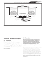
Number of Suction Outlets Per Pump - Provide at least two (2) hydraulically-balanced main drains, with
covers, as suction outlets for each circulating pump suction line. The centers of the main drains (suction outlets)
on any one (1) suction line must be at least three (3) feet apart, center to center. See Figure 1 on page 7.
The system must be built to include at least two (2) suction outlets (drains) connected to the pump whenever
the pump is running. However, if two (2) main drains run into a single suction line, the single suction line may be
equipped with a valve that will shut off both main drains from the pump. The system shall be constructed such
that it shall not allow for separate or independent shutoff or isolation of each drain. See Figure 1 on page 7.
More than one (1) pump can be connected to a single suction line as long as the requirements above are met.
Water Velocity - The maximum water velocity through the suction fitting or cover for any suction outlet must be
1.5 feet per second unless the outlet complies with the latest version of ANSI/ASME A112.19.8, the standard for
Suction Fittings For Use in Swimming Pools, Wading Pools, Spas, and Hot Tubs. In any case, do not exceed the
suction fitting’s maximum designed flow rate.
If 100% of the pump’s flow comes from the main drain system, the maximum water velocity in the pump suction
hydraulic system must be 6 feet per second or less, even if one (1) main drain (suction outlet) is completely
blocked. The flow through the remaining main drain(s) must comply with the latest version of ANSI/ASME
A112.19.8, the standard for Suction Fittings For Use in Swimming Pools, Wading Pools, Spas, and Hot Tubs.
Testing and Certification - Suction outlet covers must have been tested by a nationally recognized testing
laboratory and found to comply with the latest version of ANSI/ASME A112.19.8, the standard for Suction Fittings
For Use in Swimming Pools, Wading Pools, Spas, and Hot Tubs.
Fittings - Fittings restrict flow; for best efficiency use fewest possible fittings (but at least two (2) suction outlets).
Avoid fittings which could cause an air trap.
Pool cleaner suction fittings must conform to applicable International Association of Plumbing and Mechanical
Officials (IAPMO) standards.
SAVE THESE INSTRUCTIONS
Jandy® Pro Series Stealth™ Pumps | Operation Manual
ENGLISH
Page 7
At least
three (3) feet
Listed/certified to latest
published version of
ANSI/ASME
A112.19.8 - 2007
Anti-entrapment
Cover/Grate or Suction
Fitting, screw-fastened
to Main Drain Sump
No valves between
Tee and Main Drains
Listed/certified to latest
published version of
ANSI/ASME
A112.19.8 - 2007
Anti-entrapment
Cover/Grate or Suction
Fitting, screw-fastened
to Main Drain Sump
Suction Outlet
(Main Drain)
Suction Outlet
(Main Drain)
Valves OK between
pump and Tee
Pump
Figure 1.Number of Suction Outlets Per Pump
Section 2.General Description
2.1Introduction
This manual contains information for the proper
installation, operation and maintenance of Jandy Pro
Series Stealth (SHP) Pumps. Procedures in this manual
must be followed exactly. To obtain additional copies of
this manual contact Zodiac Pool Systems, Inc. ("Zodiac")
at 800.822.7933. For address information, see the back
cover of this manual.
2.2Description
SHP Pumps are designed to meet the needs of today’s
more hydraulically demanding pool equipment. The
pump housing, backplate, diffuser, hair and lint pot
(pump debris filter basket), and impeller are all made
from high quality thermoplastic materials. These
materials were chosen for their strength and corrosion
resistance.
The pump is driven by an electric motor directly attached
to the pump impeller. As the electric motor turns, it
causes the impeller to turn, which forces water to flow
through the pump. The water flows through the pump
inlet and then into the filter basket. The basket assembly
pre-strains and traps large particles. The water then
enters the center of the pump housing, flows through the
impeller into the diffuser, and then flows out the pump
discharge port.
Page 8
ENGLISH
Jandy® Pro Series Stealth™ Pumps | Operation Manual
Section 3.Installation
3.1
5.
The pump foundation must have adequate
drainage to prevent the motor from getting wet.
The pump needs to be protected from the rain
and sun.
6.
Upon receipt of the pump, check the carton for
damage. Open the carton and check the pump
for concealed damage, such as cracks, dents or a
bent base. If damage is found, contact the shipper
or distributor where you purchased the pump.
Proper ventilation is required for the pump to
operate normally. All motors generate heat that
must be removed by providing proper ventilation.
7.
Inspect the contents of the carton and verify
that all the parts are included. See Section 7.1,
Replacement Parts List.
Provide access for future service by leaving a
clear area around the pump. Allow plenty of
space above the pump to remove the lid and
basket for cleaning.
8.
If the equipment is under cover, provide adequate
lighting.
Plumbing
3.1.1 Preparation
1.
2.
3.1.2 Pump Location
1.
Zodiac Pool Systems, Inc. recommends installing
the pump within one (1) foot above the water
level. The pump should not be elevated more
than a few feet above the water level of the pool.
A check valve is recommended on the suction
line to the pump.
Note Better self-priming will be achieved if the pump is
installed as close as possible to the water level of the
pool.
2.
If the pump is located below water level,
isolation valves must be installed on both the
suction and return lines to prevent back flow
of pool water during any routine or required
servicing.
WARNING
Some Safety Vacuum Release System (SVRS) devices
are not compatible with installation of check valves. If
the pool has an SVRS device, be sure to confirm that it
will continue to safely operate when any check valves
are installed.
3.
The pump and other circulation equipment must
be located more than five (5) feet from the water.
Choose a location that will minimize turns in the
piping.
Note In Canada, the pump must be located a minimum of
three (3) meters [approximately ten (10) feet] from the
water (CSA C22.1).
4.
The pump must be placed on a solid foundation
that will not vibrate. To further reduce the
possibility of vibration noise, bolt the pump to
the foundation.
Note Zodiac Pool Systems, Inc. recommends bolting the
pump directly to the foundation.
3.1.3 Pipe Sizing
Note All HP ratings given in this section apply to full-rated
pumps. For help with max-rated pumps, contact
Zodiac Technical Support at 800.822.7933.
3.1.3.1
Suction Pipe
When the pump is located up to 50 feet from the pool, the
recommended minimum pipe size for the suction side of
the pump is:
• 2" for .75 to 1.5 HP*
• 2½" for 2.0 HP*
• 3" for 3.0 HP*
• 4" for 5.0 HP*
* HP refers to full-rated pumps
3.1.3.2Discharge Pipe
When the pump is located up to 50 feet from the pool, the
recommended minimum pipe size for the discharge side
of the pump is:
• 2" for .75 to 1.5 HP*
• 2½" for 2.0 HP*
• 3" for 3.0 HP*
• 4" for 5.0 HP*
* HP refers to full-rated pumps
NOTE All pipe sizes are able to withstand the pressures the
pump will deliver, but not necessarily the flow. If the
pipe is too small for the pump, or it is elevated above
water, the maximum gallons per minute (GPM) may
not be delivered. If this happens, the pump will develop
an air pocket (cavitation) that will make noise and the
pump life will be shortened.
Jandy® Pro Series Stealth™ Pumps | Operation Manual
3.1.3.3Installation Recommendations
1.
2.
If the pump is located below water level,
isolation valves must be installed on both sides
of the pump to prevent back flow of pool water
during any routine or required servicing.
To help prevent difficulty in priming, install the
suction pipe without high points (above inlet of
pump - inverted “U”s in plumbing), which can
trap air. For installations of equipment up to 100
feet from the water, refer to the pipe sizing chart,
Table 1. For installations of equipment more than
100 feet from the water, the recommended pipe
must be increased to the next size.
Table 1.
Pipe Sizing Chart for Schedule 40 PVC
Pipe
Size
Maximum Flow
Suction
(8 feet per second)
Maximum Flow
Discharge
(10 feet per second)
1½"
50 GPM (189 LPM)
65 GPM (246 LPM)
2"
85 GPM (322 LPM)
105 GPM (397 LPM)
2½"
120 GPM (454 LPM)
149 GPM (564 LPM)
3"
184 GPM (697 LPM)
230 GPM (871 LPM)
4"
317 GPM (1203 LPM) 397 GPM (1502 LPM)
3.
SHP Pumps come equipped with unions on both
the suction and discharge ports. This feature
simplifies installation and service, and eliminates
the possibility of leaks at threaded adapters.
4.
The SHP Pump must be connected to at least two
(2) hydraulically balanced main drains (suction
outlets) for each pool pump suction line. Each
drain must be provided with covers that are listed
or certified to the latest version of ANSI/ASME
A112.19.8. The suction outlets of the main drains
must be at least three (3) feet apart or at different
planes. The suction outlets can be a drain and
skimmer, two (2) drains, two (2) skimmers, or a
skimmer with an equalizer line installed. Check the
local codes for proper installation requirements.
7.
6.
Always use properly sized valves. Jandy Pro
Series Diverter Valves and Ball Valves typically
have the best flow capabilities.
Use the fewest fittings possible. Every additional
fitting has the effect of moving the equipment
farther away from the water.
size must be increased.
8.
3.2
If this is a new installation, pressure test
according to local codes. See Section 3.3,
Pressure Testing.
Electrical Installation
3.2.1 Voltage Checks
The correct voltage, as specified on the pump data plate,
is necessary for proper performance and long motor life.
Incorrect voltage will decrease the pump’s ability to
perform and could cause overheating, reduce the motor
life, and result in higher electric bills.
It is the responsibility of the electrical installer to provide
data plate operating voltage to the pump by ensuring
proper circuit sizes and wire sizes for this specific
application.
The National Electrical Code (NEC, NFPA-70) requires
all pool pump circuits be protected with a Ground Fault
Interrupter (GFCI). Therefore, it is also the responsibility
of the electrical installer to ensure that the pump circuit
is in compliance with this and all other applicable
requirements of the National Electrical Code (NEC) and
any other applicable installation codes.
CAUTION
Failure to provide data plate voltage (within 10%)
during operation will cause the motor to overheat and
void the warranty.
3.2.2 Bonding and Grounding
1.
The motor frame must be grounded to a reliable
grounding point using a solid copper conductor,
No. 8 AWG or larger. In Canada, No. 6 AWG or
larger must be used. If the pump is installed within
five (5) feet of the inside walls of the swimming
pool, spa, or hot tub, the motor frame must be
bonded to all metal parts of the swimming pool,
spa, or hot tub structure and to all electrical
equipment, metal conduit, and metal piping within
five (5) feet of the inside walls of the swimming
pool, spa, or hot tub.
2.
Bond the motor using the provided external lug.
that it cannot operate with the pump drawing water
from only one (1) main drain. At least two (2) main
drains must be connected to the pump when it is in
operation. However, if two (2) main drains run into
a single suction line, the single suction line may be
equipped with a valve which will shut off both main
drains from the pump.
The piping must be well supported and not
forced together where constant stress will be
experienced.
Page 9
Note If more than 10 suction fittings are needed, the pipe
Note To prevent entrapment, the system must be built so
5.
ENGLISH
Page 10
ENGLISH
Jandy® Pro Series Stealth™ Pumps | Operation Manual
WARNING
To avoid the risk of property damage, severe personal
injury, and/or death, always disconnect the power
source before working on a motor or its connected load.
2.
Wire size must be adequate to minimize voltage
drop during the start-up and operation of the
pump. See Table 2 for recommended wire sizes.
3.
Insulate all connections carefully to prevent
grounding or short-circuits. Sharp edges on
terminals require extra protection. To prevent wire
nuts from loosening, tape them using a suitable,
listed (UL, ETL, CSA) electrical insulating tape.
For safety, and to prevent entry of contaminants,
reinstall all conduit and terminal box covers. Do
not force connections into the conduit box.
4.
To configure the internal wiring of the pump
motor for the correct voltage, refer to the diagram
on the motor data plate.
WARNING
To avoid the risk of property damage, severe personal
injury, and/or death, make sure that the control switch
or time clock is installed in an accessible location so
that in the event of an equipment failure or a loose
plumbing fitting the equipment can be turned off. This
location must not be in the same area as the pool
pump, filter, and other equipment.
WARNING
The pump must be permanently connected to a
dedicated electrical circuit. No other equipment, lights,
appliances or outlets may be connected to the pump
circuit, with the exception of devices that may be
required to operate simultaneously with the pump,
such as a chlorinating device or heater.
3.2.3 Electrical Wiring
1.
The pump motor must be securely and
adequately grounded using the green screw
provided. Ground before attempting to connect
to an electrical power supply. Do not ground to a
gas supply line.
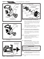
3.3
Pressure Testing
All model SHP pumps come with an additional
disposable o-ring for pressure testing. This is the blue
pressure test o-ring. See Figures 2 and 3.
CAUTION
Do not open the pump lid before pressure testing,
because the blue pressure test o-ring may fall out. If
this happens, you will need to replace it.
If you have not opened the pump lid, skip to Section
3.3.2, Conduct Pressure Test.
Table 2.Recommended Minimum Wire Size
RECOMMENDED MINIMUM WIRE SIZE FOR SHP PUMPS*
Distance from Sub-Panel
Pump Model
0-50 Feet
50-100 Feet
100-150 Feet
150-200 Feet
Voltage
Voltage
Voltage
Voltage
Branch Fuse AMPs
Class: CC, G, H, J, K,
RK, or T
230VAC
115VAC
SHPF .50HP/SHPM .75HP
15A
15A
208-230 VAC 115 VAC 208-230 VAC 115 VAC 208-230 VAC 115 VAC 208-230 VAC
14
12
12
8
10
6
8
115 VAC
SHPF .75HP/SHPM 1.0HP
15A
15A
14
12
12
8
10
6
8
6
SHPF 1.0HP/SHPM 1.5HP
15A
20A
12
10
10
8
8
6
6
4
SHPF 1.0-3PH
15A
N/A
14
N/A
12
N/A
10
N/A
8
N/A
SHPF 1.5HP/SHPM 2.0HP
15A
N/A
12
N/A
10
N/A
8
N/A
6
N/A
SHPF 1.5-3PH
15A
N/A
12
N/A
10
N/A
8
N/A
6
N/A
SHPF 2.0HP/SHPM 2.5HP
15A
N/A
12
N/A
8
N/A
6
N/A
6
N/A
SHPF 2.0-3PH
15A
N/A
12
N/A
10
N/A
8
N/A
6
N/A
SHPF 3.0HP
20A
N/A
10
N/A
8
N/A
6
N/A
4
N/A
SHPF 3.0-3PH
15A
N/A
12
N/A
8
N/A
6
N/A
6
N/A
SHPF 5.0
25A
N/A
10
N/A
8
N/A
6
N/A
6
N/A
SHPF 1.0HP-2-SPD (1)
15A
N/A
12
N/A
10
N/A
8
N/A
6
N/A
SHPF 1.5HP-2-SPD (1)
15A
N/A
12
N/A
10
N/A
8
N/A
6
N/A
SHPF 2.0HP-2-SPD (1)
15A
N/A
12
N/A
8
N/A
6
N/A
6
N/A
SHPM 1.5HP-2-SPD (1)
15A
N/A
12
N/A
10
N/A
8
N/A
6
N/A
SHPM 2.0HP-2-SPD (1)
15A
N/A
12
N/A
10
N/A
8
N/A
6
N/A
SHPM 2.5HP-2-SPD (1)
15A
N/A
12
N/A
8
N/A
6
N/A
6
N/A
6
*Assumes three (3) copper conductors in a buried conduit and 3% maximum voltage loss in branch circuit. All National Electrical Code (NEC) and local codes must
be followed. Table shows minimum wire size and branch fuse recommendations for a typical installation per NEC.
(1) Two-speed pumps are not rated for use with 208 VAC.
Jandy® Pro Series Stealth™ Pumps | Operation Manual
ENGLISH
Page 11
3.3.1.1Remove Pump Lid
Lid with
Locking
Ring
and
Seal
Blue
Pressure
Test
O-ring
Pump
Debris
Trap
Basket
(Inside
Pump)
Figure 2. Exploded View of Pump
Lid with
Locking
Ring
Seal
Blue Pressure Test O-ring
Figure 3. Blue Pressure Test O-ring in Lid
Assembly
3.3.1Replace Blue Pressure Test O-ring if
Necessary
If you open the pump lid before conducting the pressure
test, the blue o-ring will probably fall out. If this
happens, you will need to install it on the lid again before
conducting pressure testing.
There is a risk of damage to the blue o-ring during reinstallation. If you damage it when trying to re-install
it, you will need to order a new blue pressure test o-ring
(R0479000) before you begin conducting the pressure
test.
These instructions describe the proper procedures for
replacing, using, and disposing of the blue o-ring.
These instructions must be followed exactly. Read
through the instructions completely before starting
the procedure.
1.
Make sure that the pump is turned off.
2.
Make sure that the switch to the circuit breaker
that powers the pump motor is turned off.
WARNING
Turn off the pump and the main breaker in the pump
electrical circuit before starting the procedure. Failure
to comply may cause a shock hazard, resulting in
severe personal injury or death.
WARNING
Due to the potential risk of fire, electric shock, or
injuries to persons, Jandy Pro Series Pumps must be
installed in accordance with the National Electrical
Code® (NEC), in the USA, or the Canadian Electrical
Code (CEC) in Canada. All applicable local codes
must also be followed.
The NEC may be obtained by contacting the
National Fire Protection Association (NFPA) at
1-800-344-3555 or 1-617-770-3000.
3.
Make sure all necessary isolation valves are
closed to prevent pool water from reaching the
pump.
4.
Following the markings on the locking ring, turn
the ring counter-clockwise until the ‘START’
markings align with the ports.
5.
Carefully remove the lid with locking ring.
3.3.1.2Replace Blue O-ring
1.
Turn the lid with locking ring upside down and
place it on a stable surface.
2.
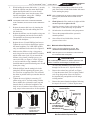
Place the blue o-ring on the step located ¼" from
the bottom of the lid. See Figure 4.
3.
Make sure that the o-ring is properly seated. It
helps to “place” the o-ring on the step rather than
to “roll” it on. That prevents it from rolling off.
NOTE The blue o-ring sits approximately ¼" away from the
seal. See Figure 4.
4.
Carefully install the lid, making sure that the blue
pressure test o-ring sits in the housing without
“binding” or “rolling” off.
5.
Following the markings on the locking ring,
align ‘START’ markings with the ports and turn
clockwise until ‘LOCKED’ markings align with
the ports. Do not tighten past the ‘LOCKED’
marking.
Page 12
ENGLISH
Jandy® Pro Series Stealth™ Pumps | Operation Manual
Upside Down View of
Bottom of Lid
4.
Observe the system for leaks and/or pressure
decay.
5.
If there are lid leaks, repeat steps 1-3. For
technical support, call 800.822.7933.
6.
Discard the blue pressure test o-ring after
successfully completing the test.
Section 4.Operation
Groove where
Seal is Seated
Step where
O-ring is Seated
Figure 4. Placement of Blue Pressure Test O-ring
3.3.2 Conduct Pressure Test
WARNING
When pressure testing a system with water, air is
often trapped in the system during the filling process.
This air will compress when the system is pressurized. Should the system fail, this trapped air can
propel debris at a high speed and cause injury. Every
effort to remove trapped air must be taken, including
opening the bleed valve on the filter and loosening
the pump basket lid while filling the pump.
WARNING
Trapped air in system can cause filter lid to be blown
off, which can result in death, serious personal injury,
or property damage. Be sure all air is properly out
of system before operating. DO NOT USE COMPRESSED AIR TO PRESSURE TEST OR CHECK
FOR LEAKS.
WARNING
When pressure testing the system with water, it is
very important to make sure that the pump basket lid
is completely secure.
WARNING
Do not pressure test above 35 PSI. Pressure
testing must be done by a trained pool professional.
Circulation equipment that is not tested properly can
fail, which could result in severe injury or property
damage.
1.
2.
3.
Fill the system with water, using care to
eliminate trapped air.
Pressurize the system with water to no more
than 35 PSI.
Close the valve to trap pressurized water in the
system.
4.1
Start-up
CAUTION
Never run the pump without water. Running the pump
“dry” for any length of time can cause severe damage
to both the pump and motor and will void the warranty.
If this is a new pool installation, make sure all piping
is clear of construction debris and has been properly
pressure tested. The filter should be checked for proper
installation, verifying all connections and clamps are
secure according to the manufacturer's recommendations.
WARNING
To avoid risk of damage or injury, verify that all power
is turned off before starting this procedure.
1.
Release all pressure from the system and open
the filter pressure release valve.
2.
If the pump is located below the water level of
the pool, opening the filter pressure release valve
will prime the pump with water.
3.
If the pump is located above the water level of
the pool, remove the lid and fill the basket with
water before starting the pump.
4.
Prior to replacing the lid, check for debris around
the lid o-ring seat. Debris around the lid o-ring
seat will cause air to leak into the system, and
make it difficult to prime the pump.
5.
Hand-tighten the lid to make an air tight seal. Do
not use any tools to tighten the lid, hand-tighten
only. Make sure all valves are open and the
unions are tight.
6.
Turn on the power to the pump. Then turn on
the pump.
7.
Once all the air has left the filter, close the
pressure release valve.
8.
The pump should prime. The time it takes to
prime will depend on the elevation and length of
pipe used on the suction supply pipe. See Section
3.1.3.3 for proper elevation and pipe size.
Jandy® Pro Series Stealth™ Pumps | Operation Manual
9.
If the pump does not prime and all the
instructions to this point have been followed,
check for a suction leak and then repeat Steps 2
through 7.
Section 5. Service and
Maintenance
5.1Routine Maintenance
Inspect the pump basket for debris by looking through
the clear pump lid. Remove any debris, because as debris
accumulates, it will begin to block the flow of water
through the pump. Keep the basket clean to improve the
performance of the pump.
1.
2.
Turn off the power to the pump. If the pump is
located below the water level, close the isolation
valves on the suction and discharge sides of the
pump to prevent a backflow of water.
Turn the lid's locking ring counter-clockwise
until 'START' aligns with the ports. (You may
use a tool for leverage to open the lid, but never
to tighten the lid when closing it.) Carefully
remove the lid.
CAUTION
ENGLISH
Page 13
10. Turn on the power to the pump. Once all the
air has been evacuated from the filter, close the
pressure release valve.
5.2
Winterizing the Pump
CAUTION
The pump must be protected when freezing temperatures are expected. Allowing the pump to freeze will
cause severe damage and void the warranty.
CAUTION
Do not use antifreeze solutions in the pool, spa,
or hot tub systems! Antifreeze is highly toxic and
may damage the circulation system. The only exception to this is Propylene Glycol. For more information
see your local pool/spa supply store or contact a
qualified swimming pool service company.
1.
Drain all water from the pump, system
equipment, and piping.
2.
Remove the two drain plugs. Store the drain
plugs in a safe location and reinstall them when
the cold weather season is over. Do not lose the
o-rings. (Drain Plug with O-ring Set, R0446000)
3.
Keep the motor covered and dry.
Note Covering the pump with plastic will create
condensation, and this moisture will damage the
pump. The best way to protect your pump is to have
a qualified service technician or electrician properly
disconnect the electrical wiring at the switch or junction
box. Once the power is removed, the two unions can
be loosened and the pump stored indoors. For safety,
and to prevent entry of contaminants, reinstall all
conduit and terminal box covers.
A misaligned basket will cause the lid to be improperly seated, allowing an air leak which could result in
pump damage.
3.
Lift the basket out of the pump.
4.
Dispose of the debris and thoroughly clean the
basket, making sure all the holes are open. Using
a garden hose, spray the basket from the outside
to help clear the holes. Use your hands to remove
any remaining debris.
4.
Replace the basket in the pump by aligning
the opening with the suction pipe. If aligned
properly, the basket will drop easily into place.
Do not force into place.
When the system is reopened for operation, make
sure all piping, valves, wiring, and equipment
are in accordance with the manufacturer's
recommendations. Pay close attention to the filter
and electrical connections.
5.
The pump must be primed prior to starting; refer
to Section 4.1, Start-up.
5.
6.
Prior to replacing the lid, check for debris around
the lid o-ring seat, as this will cause air to leak
into the system. Clean the lid o-ring and place it
on the lid.
7.
Hand-tighten the lid to make an air tight seal. Do
not use any tools to tighten the lid: hand-tighten
only.
8.
Verify that all valves have been returned to the
proper position for normal operation.
9.
Open the pressure release valve on the filter, and
make sure it is clean and ready for operation.
Page 14
ENGLISH
Jandy® Pro Series Stealth™ Pumps | Operation Manual
Section 6.Troubleshooting and Repair
Zodiac Pool Systems, Inc. strongly recommends that you call a qualified service technician to perform any repairs on
the filter/pump system. To locate an independent service company, check your local yellow pages or visit www.jandy.
com and click on "Product Support."
6.1Troubleshooting
Symptom
The cleaning/circulating
system is not operating
correctly.
Possible Problem/Solution
Verify that skimmer baskets, pump basket and other screens are clean. Clean as
necessary.
Check filter and clean as necessary.
Check valve positions. Adjust as necessary.
NOTE Multiple pieces of equipment operating at one time (for example, waterfalls,
spa jets, and surface returns) may prevent the cleaning system from working
properly.
Check the cleaning system manually to ensure that the system is adjusted
according to the manufacturer's recommendations.
Bubbles present in the pump
basket.
Air in system. Check the pool or spa water level to ensure it is at the proper level
and that air is not being drawn into the suction piping. If the water is at normal level,
turn off the pump. Remove the lid and check for debris around the lid o-ring seat or
improper installation of the lid seal, as this either of these conditions will cause air to
leak into the system. Clean the lid o-ring and place on the lid. Hand-tighten the lid
to make an air tight seal. Do not use any tools to tighten the lid. Turn the pump
back on.
Air leaks are still present.
Check the suction side piping union. While the pump is running, try to tighten the
union. If this does not stop the air leak, turn off the pump. Loosen both unions and
slide the pump out of the way. Remove, clean and re-install both union o-rings.
Reposition the pump next to the piping and secure the union nuts to the pump. With
clean union o-rings, hand-tightening of the unions should create a seal. If the unions
still do not seal, gently tighten with a large pair of tongue-and-groove pliers.
Do not over-tighten.
There is no air in the system,
but the pressure is still low.
It is possible that debris is caught in the pump impeller. The pump impeller moves
the water, and the vanes in the impeller can become blocked with debris. See
Section 6.2, Service Technician Maintenance, 6.2.1, Blocked Impeller, for more
information.
There is no debris blocking
the impeller and the pressure
is still low.
The pump impeller and diffuser are showing signs of normal wear. Have a qualified
service technician check the impeller and diffuser and replace as necessary.
If the pump is part of a relatively new installation, it could be an electrical problem.
Contact a qualified service technician. Have the technician check for loose electrical
connections and check the voltage at the pump motor while it is in operation. The
voltage must be within 10% of the motor's data plate rating. If the voltage is not
within 10%, contact a qualified electrician and/or the local power service provider.
Pump seal is leaking air. Have a qualified service technician replace the seal.
The pump is leaking water
between the motor and pump
body.
This is caused by a damaged or failed mechanical seal. Replace the seal. See
Section 6.2, Service Technician Maintenance, 6.2.4, Mechanical Seal Replacement.
The pump gets hot and shuts
off periodically.
Ensure that there is adequate room around the motor to circulate air and keep the
motor cool. Have a qualified electrician check for loose connections and check the
voltage at the pump motor while it is in operation. The voltage must be within 10%
of the motor's data plate rating. If the voltage is not within 10%, contact a qualified
electrician and/or the local power service provider.
Jandy® Pro Series Stealth™ Pumps | Operation Manual
6.2
Service Technician Maintenance
2.
Turn off any valves to prevent pool water from
Reaching the pump. Drain the water from the
pump by loosening the unions or removing the
drain plugs.
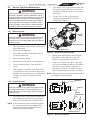
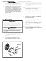
3.
Using a 9/16" wrench, loosen the bolts
connecting the pump body to the motor
backplate. See Figure 5.
WARNING
This pump must be serviced by a professional service
technician, qualified in pool/spa installation. The following procedures must be followed exactly. Improper
installation and/or operation can create dangerous
electrical hazards, which can cause high voltages to
run through the electrical system, possibly causing
property damage, serious injury, or death. Improper
installation and/or operation will void the warranty.
Page 15
ENGLISH
Bolts (8)
6.2.1 Blocked Impeller
WARNING
Pump
Body
While servicing the pump, switch off the circuit breakers at the power source. Severe personal injury or
death may occur if the pump starts while your hand is
inside the pump.
1.
Turn off the pump. Switch off the circuit breaker
to the pump motor.
2.
Remove the lid and basket.
3.
Look inside the pump for any debris. Remove
any debris found inside.
4.
Replace the basket and lid.
5.
Switch on the circuit breaker to the pump motor.
6.
Turn on the pump, and see if the problem is
solved.
7.
If the impeller is still blocked with debris and it
is not possible to remove the debris using steps 2
through 4, the pump will need to be disassembled
in order to access the inlet and outlet of the
impeller.
Motor Backplate
Motor Shaft Cover
Figure 5.Remove the Pump Housing
4.
Pull the motor and backplate out of the pump
body. Remove the pump body o-ring. The
impeller is connected to the motor shaft.
5.
Using a No. 1 Phillips screwdriver, remove the
two (2) screws holding the diffuser. (The diffuser
is the cover over the impeller.) Then remove
the diffuser, see Figure 6. The SHPF 5.0 uses a
different diffuser than other models. See Figure 8.
Note At this point you have access to the inlet and outlet of
the impeller to remove any debris.
Backplate
6.2.2Impeller Removal
WARNING
While servicing the pump, switch off the circuit breakers at the power source. Severe personal injury or
death may occur if the pump starts while your hand is
inside the pump.
1.
Diffuser
Motor
Screws
with Washers
(2)
Turn off the pump. Switch off the circuit breaker
to the pump motor. If you are not replacing the
motor, do not disconnect the electrical wiring.
Note If you are replacing the motor, Zodiac Pool Systems,
Inc., strongly recommends that a qualified service
technician or electrician properly disconnect the
electrical wiring at the pump motor.
Motor
Diffuser O-ring
Figure 6.Remove the Diffuser
Page 16
ENGLISH
Jandy® Pro Series Stealth™ Pumps | Operation Manual
Diffuser O-Ring
Pump Body
Diffuser Screws with Washers (2)
Self Sealing Left
Handed Screw
Backplate
O-ring
Diffuser
O-ring
Diffuser
Diffuser
Impeller
Mechanical
Seal
O-ring Location
for SHP Only
Backplate
O-ring Location
for PHP/MHP Only
Figure 10.Diffuser and Impeller Exploded View
Figure 7.Location of the Diffuser O-ring
6.
Remove the motor shaft cover on the back of the
motor by twisting the hex-head screw with a 90°
crescent wrench, see Figure 5. The motor shaft
will be exposed.
7.
Hold the exposed motor shaft with a ½" wrench
while removing the impeller center screw using a
No. 3 Phillips screwdriver. See Figure 9.
Pump Body
Diffuser
O-ring
Note The impeller center screw is a left-hand threaded
screw. Therefore, turn the screw clockwise to loosen.
8.
Hold the motor shaft with a ½" wrench while
unscrewing the impeller from the motor shaft
with your hand.
Note The impeller is a right-handed thread, therefore turn
the impeller counter-clockwise to unscrew.
Diffuser
9.
Figure 8.Location of the Diffuser O-ring on a SHPF
5.0 HP Only
6.2.3Impeller Replacement
1.
Self Sealing Left
Handed Screw
Inspect the impeller and diffuser for signs of
rubbing and/or damage.
Press the new carbon face seal half, see Figure
11 on the motor shaft using a twisting motion.
Make sure the carbon surface is facing toward
the ceramic ring in the backplate.
CAUTION
VERY IMPORTANT! Grasp the lower portion of the
seal (opposite the carbon face) when installing the
seal, or it will be damaged.
Note To assist assembly, only use water and soap solution
Impeller
Backplate
Mechanical Seal
Figure 9.Remove the Impeller
as a lubricant. Any other lubricant will destroy the seal
after a short period of time.
Note Exercise great care to keep the seal and mating parts
clean.
Jandy® Pro Series Stealth™ Pumps | Operation Manual
2.
While holding the motor shaft with a ½" wrench,
thread the impeller onto the motor shaft. Handtighten the impeller until it is secure. Install
the impeller center screw into the center of the
impeller and tighten, using a No. 3 Phillips
screwdriver. Do not overtighten.
Note The impeller center screw is a left-hand threaded
screw. Therefore, turn the screw counter-clockwise to
tighten.
3.
4.
5.
6.
7.
8.
Replace the motor shaft cover by inserting the
cover tabs into the slots and rotating the cover
90º clockwise.
Replace the diffuser over the impeller, using care
to insert alignment pins into the correct holes.
The molded-in arrow must point toward the
handle of the backplate.
Replace the two (2) small Phillips head screws.
Tighten the screws to draw the diffuser against
the motor backplate. For 5.0HP, SWF models
only, use additional lock washers. See Figure 12.
Make sure the diffuser o-ring, o-ring groove,
and o-ring seal area are clean and free of debris,
which could cause a leak. If you removed the
diffuser o-ring, install it into the groove you
removed it from, see Figures 7 and 8. If grease
is used to retain the o-ring, it must be silicone
based. Do not use petroleum-based grease. It will
destroy the o-ring.
Slide the diffuser into the mating hole in the
pump body. While supporting the motor, start
two (2)screws on opposite sides. This will hold
the motor in position while you start the other six
(6) screws.
Tighten the screws lightly in a crossing “X”
pattern using a 9/16" wrench, starting with the
inner (middle) four (4) then the outer (top and
bottom) four (4) to draw the backplate to the
body in an even manner. Once all the screws are
snug, torque in the same order to 18 foot-pounds.
Carbon Seal Surface
• Ceramic Face Seal
• Backplate Seal
• Carbon Face/ Spring
Side of Seal
• Impeller Side of the
Mechanical Seal
Figure 11.Replace the Mechanical Seal
9.
Page 17
ENGLISH
If the pump is located above water level of the
pool, remove the lid and fill the basket with water
before starting the pump.
Note Prior to replacing the lid, check for debris around the
lid o-ring seat, as this will cause air leaks into the
system.
10. Hand-tighten the lid to make an air tight seal. Do
not use any tools to tighten the lid.
11. Open the pressure release valve on the filter, and
make sure it is clean and ready for operation.
12. Switch on the circuit breaker to the pump motor.
13. Turn on the pump and check the system for
normal operation.
14. Once all the air has left the filter, close the
pressure release valve.
6.2.4 Mechanical Seal Replacement
Note This is a two part replacement process. The
mechanical seal must be replaced as a set.
Note Refer to Figure 12 for an illustration of the location of
the mechanical seal and impeller.
WARNING
Do not damage the ceramic or carbon surfaces of the
seals. If surfaces are damaged, leaks will occur.
1.
To access the mechanical seal, follow steps 1
through 8 of Section 6.2.2, Impeller Removal.
2.
Remove the carbon face seal half, see Figure
11 from the motor shaft. This is a spring-loaded
seal. Grasp the portion of the seal closest to
the impeller body and pull the seal off using a
twisting motion.
3.
Remove the motor from the backplate following
the steps in Section 6.2.5, Motor Replacement.
Backplate
Self Sealing Left
Handed Screw
Diffuser
Impeller
Screws and
Washers (2)
Mechanical Seal
Lock Washers (2)
For 5.0HP SHP &
SWF Models Only
Diffuser O-ring
Figure 12. Backplate, Impeller, Diffuser, and
Mechanical Seal Exploded View
Page 18
ENGLISH
Jandy® Pro Series Stealth™ Pumps | Operation Manual
4.
Place the backplate o-ring side down and force
the ceramic seal out using a screwdriver or drift.
5.
Turn the backplate o-ring side up and insert the
new ceramic seal side into the backplate. Use
great care to press the seal in squarely with your
fingers. The ceramic is easily damaged and must
be pressed in using only your fingers or soft
tools. Do not use any lubricant other than water
and soap solution.
6.
Install the motor following the steps in
Section 6.2.5, Motor Replacement.
7.
Install the backplate following the steps in
Section 6.2.3, Impeller Replacement.
6.2.5 Motor Replacement
CAUTION
To ensure continued safety and reliable operation,
Zodiac Pool Systems, Inc. requires that you replace
the motor with a motor that has the identical HP rating
and service factor (Zodiac Pool Systems, Inc. approved only).
WARNING
To avoid the risk of property damage, severe personal
injury, or death, turn off the pump and switch off the
circuit breaker to the pump motor before beginning
this procedure.
1.
Have a qualified service technician or electrician
properly disconnect the electrical wiring at the
pump motor.
2.
To disassemble the pump housing from the
motor, follow steps 1 through 8 in Section 6.2.2,
Impeller Removal.
Backplate
Bolts and
Washers (4)
Starting
Capacitor
Motor
Figure 13. Backplate Assembly
3.
Place the backplate motor assembly o-ring side
down and unscrew the four (4) 9/16" screws and
remove the motor.
Note Before removing the backplate, note the alignment of
the backplate to the motor. See Figure 13.
4.
If installing a new motor, remove the protective
plastic cap from the motor shaft. Place the motor
on the backplate so that the opening in the motor
faces the bottom of the backplate. The starting
capacitor on the motor should be at the
12 o'clock position.
5.
Replace the four (4) bolts and washers holding
the backplate to the motor.
6.
To reassemble the pump after replacing the
motor, follow steps 1 through 14 of Section 6.2.3,
Impeller Replacement.
7.
Have a qualified service technician or electrician
properly connect the electrical wiring at the
pump motor.
Note Zodiac Pool Systems, Inc. recommends that the
mechanical seals be replaced at the same time the
motor is replaced. See Section 6.2.4, Mechanical Seal
Replacement, for details.
Jandy® Pro Series Stealth™ Pumps | Operation Manual
ENGLISH
Page 19
Section 7. Product Specifications and Technical Data
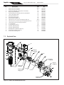
7.1Replacement Parts List
To order or purchase parts for Zodiac® pumps, contact your nearest Zodiac dealer. If they cannot supply you with what
you need, contact Zodiac technical support at 800.822.7933 or send an e-mail message to:
[email protected].
Key
No.
1
1
1
1
1
1
1
1
1
1
1
1
1
1
1
1
1
1
1
1
1
1
2
2
3
3
3
3
3
3
3
3
3
3
3
3
3
Description
Single-speed Motor & Hardware, SHPF
Single-speed Motor & Hardware, SHPF
Single-speed Motor & Hardware, SHPF
Single-speed Motor & Hardware, SHPF
Single-speed Motor & Hardware, SHPF
Single-speed Motor & Hardware, SHPF
Single-speed Motor & Hardware, SHPF
Single-speed Motor & Hardware, SHPM
Single-speed Motor & Hardware, SHPM
Single-speed Motor & Hardware, SHPM
Single-speed Motor & Hardware, SHPM
Single-speed Motor & Hardware, SHPM
Two-speed Motor & Hardware, SHPM
Two-speed Motor & Hardware, SHPM
Two-speed Motor & Hardware, SHPM
Single-speed Motor & Hardware, SHPF, 3 Phase
Single-speed Motor & Hardware, SHPF, 3 Phase
Single-speed Motor & Hardware, SHPF, 3 Phase
Single-speed Motor & Hardware, SHPF, 3 Phase
Two-speed Motor & Hardware, SHPF
Two-speed Motor & Hardware, SHPF
Two-speed Motor & Hardware, SHPF
Backplate Kit w/Hardware, O-ring & Mech Seals, SHPF/SHPM
Backplate Kit w/Hardware, O-ring & Mech Seals, SHPF
Impeller & Diffuser w/Screw & O-ring, SHPF
Impeller & Diffuser w/Screw & O-ring, SHPF
Impeller & Diffuser w/Screw & O-ring, SHPF
Impeller & Diffuser w/Screw & O-ring, SHPF
Impeller & Diffuser w/Screw & O-ring, SHPF
Impeller & Diffuser w/Screw & O-ring, SHPF
Impeller & Diffuser w/Screw & O-ring, SHPF
Impeller & Diffuser w/Screw & O-ring, SHPM
Impeller & Diffuser w/Screw & O-ring, SHPM
Impeller & Diffuser w/Screw & O-ring, SHPM
Impeller & Diffuser w/Screw & O-ring, SHPM
Impeller & Diffuser w/Screw & O-ring, SHPM
Screw w/O-ring, Self-sealing
Model No.
(HP)
.50
.75
1.0
1.5
2.0
3.0
5.0
.75
1.0
1.5
2.0
2.5
1.5
2.0
2.5
1.0
1.5
2.0
3.0
1.0
1.5
2.0
.50-3.0
5.0
.50
.75
1.0, 1.0-2
1.5, 1.5-2
2.0, 2.0-2
3.0
5.0
0.75
1.0
1.5
2.0, 2.0-2
2.5, 2.5-2
All
Order Part
No.
R0445114
R0445101
R0445102
R0445103
R0445104
R0445105
R0490200
R0479301
R0479302
R0479303
R0479304
R0479305
R0479307
R0479308
R0479309
R0479101
R0479102
R0479103
R0479104
R0445113
R0445106
R0445107
R0445200
R0445201
R0445301
R0445302
R0445303
R0445304
R0445305
R0445306
R0445307
R0445301
R0445302
R0445303
R0445304
R0445305
R0445302-06
Page 20
Key
No.
4
4
5
6
7
8
9
10
11
12
12
13
14
15
16
16
17
18
19
7.2
ENGLISH
Jandy® Pro Series Stealth™ Pumps | Operation Manual
Model No.
(HP)
Description
Diffuser w/O-ring & Hardware
Diffuser w/O-ring & Hardware
Mechanical Shaft Seal (1 Set) (Carbon and Ceramic)
Body, Pump, SHPF/SHPM
Motor Mounting Foot Assembly w/Screws, SHPF/SHPM
Lid w/ Locking Ring & Seal
Blue Pressure Test O-ring
Pump Debris Filter Basket
Drain Plug w/O-ring (Set of 2)
Tail Piece (2" by 2½"), O-ring & Coupling Nut (Set of 2)
Tail Piece (2½" by 3") with O-ring and Coupling Nut (Set of 2)
Lid Seal and Lid O-ring (Lid O-ring Not Shown)
O-ring, Backplate
O-ring, Tail Piece (Set of 2)
Hardware, Diffuser/Impeller
Hardware, Diffuser/Impeller
Backplate Bolts and Washers (Set of 8)
Motor Bolts and Washers (Set of 4)
Screws, Motor Mounting Foot
.50-3.0
5.0
All
All
All
All
All
All
All
.50-2.5
3.0-5.0
All
All
All
.50-3.0
5.0
All
All
All
Order Part
No.
R0445400
R0445401
R0479400
R0445601
R0445700
R0445800
R0479000
R0445900
R0446000
R0446101
R0446102
R0446200
R0446300
R0446400
R0446500
R0446501
R0446600
R0446700
R0446800
Exploded View
12
12
15
6
15
8
4 (qty 2),
16 (qty 2)
13
3, 4
3
2, 5
9
2
10
2 (qty 8),
17 (qty 8)
11 (qty 2)
1 (qty 4),
18 (qty 4)
4 (qty 2),
16 (qty 2)
4 (qty 2),
16 (qty 2)
1
3, 16
2, 14
7 (qty 2),
19 (qty 2)
Figure 14. SHPF and SHPM Exploded View
7
Jandy® Pro Series Stealth™ Pumps | Operation Manual
7.3
ENGLISH
Page 21
SHPF and SHPM Pump Curves
Jandy Stealth™ Series High Head Pumps
Full-Rated (SHPF) and Max-Rated (SHPM)
120
50
110
45
100
Total Dynamic Head (FEET of H2O)
SHPF 5.0
80
70
35
30
60
SHPF 3.0/
SHPF 3.0-3PH
50
SHPF 2.0/
SHPM 2.5
Low Speed
40
30
SHPF 2.0/
SHPF 2.0-3PH/
SHPM 2.5
SHPF .50/
SHPM .75
20
SHPF 1.5/
SHPM 2.0
Low Speed
10
0
0
10
20
SHPF .75/
SHPM 1.0
SHPF 1.0/
Low Speed
30
40
50
60
70
80
SHPF 1.0/
SHPF 1.0-3PH/
SHPM 1.5
SHPF 1.5/
SHPF 1.5-3PH/
SHPM 2.0
25
20
15
10
5
0
90 100 110 120 130 140 150 160 170 180 190 200 210 220 230 240 250
Flow Rate, Gallons Per Minute (GPM)
Pounds Per Square Inch (PSI)
40
90
Page 22
7.4
ENGLISH
Jandy® Pro Series Stealth™ Pumps | Operation Manual
Physical and Operational Specifications
7.4.1 SHPF Pump Specifications
Model No.
HP
Voltage
Amps
Pipe Size
Carton Weight
Overall Length 'A'
SHPF .50
.50
208-230/115
4.4-4.5/8.8
2-2½"
30 lbs.
311/8"
SHPF .75
.75
208-230/115
6.0-5.6/11.2
2-2½"
43 lbs.
317/8"
SHPF 1.0
1.0
208-230/115
7.8-7.4/14.8
2-2½"
45 lbs.
32¼"
SHPF 1.5
1.5
208-230
9.6-8.8
2-2½"
50 lbs.
325/8"
SHPF 2.0
2.0
208-230
11.0-10.0
2-2½"
57 lbs.
331/8"
SHPF 3.0
3.0
208-230
15.0-13.6
2½-3"
63 lbs.
331/8"
SHPF 1.0-2SPD
1.0
230
7.2/3.0
2-2½"
52 lbs.
331/8"
SHPF 1.5-2SPD
2.0
230
10.0/3.5
2-2½"
57 lbs.
335/8"
SHPF 2.0-2SPD
2.5
230
11.0/4.0
2-2½"
64 lbs.
331/8"
SHPF 1.0-3PH
1.0
208-230/460
5.0-4.6/2.3
2-2½"
55 lbs.
317/8"
SHPF 1.5-3PH
1.5
208-230/460
6.4-5.8/2.9
2-2½"
57 lbs.
321/8"
SHPF 2.0-3PH
2.0
208-230/460
7.1-6.8/3.4
2-2½"
64 lbs.
325/8"
SHPF 3.0-3PH
3.0
208-230/460
9.0-8.6/4.3
2½-3"
62 lbs.
325/8"
SHPF 5.0
5.0
230
19.4
4"
68 lbs.
33¾"
HP
Voltage
Amps
Pipe Size
Carton Weight
Overall Length 'A'
SHPM .75
.75
208-230/115
4.4-4.5/8.8
2-2½"
30 lbs.
311/8"
SHPM 1.0
1.0
208-230/115
6.0-5.6/11.2
2-2½"
43 lbs.
317/8"
SHPM 1.5
1.5
208-230/115
7.8-7.4/14.8
2-2½"
45 lbs.
32¼"
SHPM 2.0
2.0
208-230
9.6-8.8
2-2½"
50 lbs.
325/8"
SHPM 2.5
2.5
208-230
11.0-10.0
2-2½"
57 lbs.
331/8"
SHPM 1.5-2SPD
1.5
230
7.2/3.0
2-2½"
52 lbs.
321/8"
SHPM 2.0-2SPD
2.0
230
10.0/3.5
2-2½"
57 lbs.
325/8"
SHPM 2.5-2SPD
2.5
230
11.0/4.0
2-2½"
64 lbs.
331/8"
7.4.2 SHPM Pump Specifications
Model No.
Jandy® Pro Series Stealth™ Pumps | Operation Manual
ENGLISH
Page 23
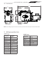
7.4.3 Pump Dimensions
'A'
113/8"
161/8"
15¼"
103/8"
103/8"
9"
14¾"
Bolt Holes,
Center to Center
Front Edge of Union to Center
of Bolt Holes
Note When installing pump, leave a minimum of two feet (2 ft) of clearance above the pump for removal of strainer basket.
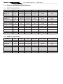
7.5
SHP Replacement Motor Guide
SHPF Pumps
SHPM Pumps
Pump Model
A.O Smith /
Century
Pump Model
SHPF .50
B845
A.O Smith/
Century
SHPF .75
B661, B2661
SHPM 1.0
B863SE
SHPF 1.0
B841, B2841
SHPM 1.5
B864SE
SHPF 1.5
B842, B2842
SHPM 2.0
B865SE
SHPF 2.0
B843, B2843
SHPM 2.5
B866SE
SHPF 3.0
B844, B2844
SHPM 1.5 2SPD
B982, B2982
SHPF 1.0-3PH
H635
SHPM 2.0 2SPD
B983, B2983
SHPF 1.5-3PH
H636
SHPM 2.5 2SPD
B984, B2984
SHPF 2.0-3PH
H637
SHPF 3.0-3PH
H755
SHPF 1.0-2SPD
B982, B2982
SHPF 1.5-2SPD
B983, B2983
SHPF 2.0-2SPD
B984, B2984
SHPF 5.0
B1000
Zodiac Pool Systems, Inc.
2620 Commerce Way, Vista, CA 92081
1.800.822.7933 | www.ZodiacPoolSystems.com
CONFORMS TO UL 1081
CERTIFIED TO CSA C22.2 NO 108
ZODIAC ® is a registered trademark of Zodiac International, S.A.S.U., used under license.
All trademarks referenced herein are the property of their respective owners.
©2012 Zodiac Pool Systems, Inc. H0573800 Rev J 1204


![[ For FX951-51 -up ] Service Manual](http://vs1.manualzilla.com/store/data/006022140_1-0f4cb22e78fbda3a4f7c4fb90e43baab-150x150.png)