1
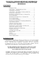
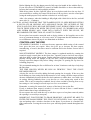
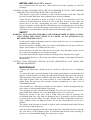
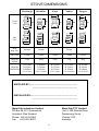
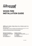
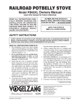
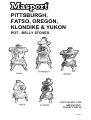
PITTSBURGH,
FATSO, OREGON,
KLONDIKE & YUKON
POT - BELLY STOVES
INSTALLING AND
OPERATING
INSTRUCTIONS
585845
THIS BOOK CONTAINS IMPORTANT INFORMATION.
PLEASE KEEP IT IN A SAFE PLACE FOR FUTURE
REFERENCE.
CONTENTS
INTRODUCTION..................................................................... 1
UNPACKING – PITTSBURGH & FATSO............................... 2
STEADIHEAT CONTROL....................................................... 2
UNPACKING – KLONDIKE, YUKON & OREGON .............. 3
INSTALLING THE STOVE ..................................................... 3
MINIMUM UNSHIELDED WALL CLEARANCES ................ 4
WALL SHIELDING ................................................................. 4
MINIMUM SHIELDED WALL CLEARANCES.................. 4, 5
WALL SHIELD SIZES ............................................................. 5
WALL SHIELD FINISHES....................................................... 5
HEARTH (FLOOR PROTECTOR) REQUIREMENTS............ 5
FLUE INSTALLATION............................................................ 6
FIREPLACE INSTALLATION................................................. 6
MANTEL-SHELF SHIELDING................................................ 6
INSTALLING A STOVE WITH A WATER COIL................... 7
OPERATING INSTRUCTIONS ............................................... 8
BEFORE LIGHTING THE FIRST FIRE................................... 8
LIGHTING THE FIRE.............................................................. 8
CONTROLLING THE FIRE..................................................... 9
REFUELLING ........................................................................ 10
SAFETY ................................................................................. 10
MAINTENANCE.................................................................... 10
STOVE DIMENSIONS........................................................... 11
INTRODUCTION
Congratulations on purchasing a Masport pot-belly stove. If correctly installed
and operated according to these instructions it will give many years of reliable
service. Following these installation instructions and the instructions
accompanying your flue kit will ensure that the heater complies with the
requirements of the appropriate Safety Standard AS/NZS 2918.
WE RECOMMEND THAT THE INSTALLATION OF YOUR
MASPORT HEATER BE CARRIED OUT BY A SUITABLY
QUALIFIED SPECIALIST INSTALLER.
CAUTION. SURFACES ON RADIANT HEATERS CAN BECOME VERY HOT. IF
CHILDREN OR ELDERLY AND INFIRM PERSONS MIGHT ACCIDENTALLY
TOUCH THE HEATER WHILE IT IS OPERATING, WE RECOMMEND THE
INSTALLATION OF SUITABLE PROTECTIVE GUARDING.
1
UNPACKING – PITTSBURGH & FATSO
To facilitate shipping, the top belly is packed upside down inside the bottom belly.
First bolt the four legs securely to the base. If a water heating coil is to be fitted, remove
the two cover plugs in the bottom belly and insert the coil, securing it with the backing
nuts provided. Check that the coil rises continuously from the bottom (inlet) to the top
(outlet). If it does not do so, water flow may be hampered and steam formation in the
pipe may cause hammering noises.
Before fitting the top belly, squeeze a bead of sealant, from the tube provided, and
spread it around the mating surfaces on the rims of the top and bottom bellies. Once the
bellies are correctly assembled, fasten them securely together with the bolts provided.
The sealant is water soluble, and can be washed from the hands with soap and water.
Any excess sealant which emerges from the joint after assembly will harden during the
first firing and may then be chipped away.
The FATSO has a flat internal baffle plate which must be fitted into the top belly. Insert
it against the inside top of the top chamber with the curved edge down and the word
‘FRONT’ facing inward. Slide the plate around on the ridge in the top chamber until the
top edge of the plate engages behind the post hanging down inside the top chamber. The
notch in the plate should be against the post.
STEADIHEAT CONTROL. In some countries, this control is fitted to some potbelly models. If you have one, follow the steps below when fitting it to the stove. You
may prefer to fit it after the stove and flue are in their final position in order to ensure
that it is not damaged during the installation.
The control bracket is shipped in the ash box below the fire grate. Using the screw
provided, mount the bracket on the underside of the casting directly below the flue
socket. The control lever points away from the stove. Check that the air metering flap
(at the back of the ash box) can move open and shut freely without catching or binding
and check that it closes fully under its own weight. The ball chain connects between the
control lever and the flap and the excess length of chain allowed for adjusting the action
should be at the bottom. Connect the ball chain to the flap with the special fitting
supplied, selecting the ball that gives a gap of 5 to 15 mm between the bottom edge of
the flap and the ash box when the control lever is fully down.
2
UNPACKING – KLONDIKE, YUKON AND OREGON
These models are shipped with the bellies in their final orientation, but the joint between
the top and bottom bellies has yet to be sealed. Before doing this, the OREGON has a
baffle plate to be fitted, and the YUKON has a baffle plate and a flue elbow (or optional
straight socket) to be assembled. Additionally, any of the three models may be fitted
with a waterheating coil.
To fit the water coil, remove the mounting hole plugs, apply sealant to the belly joint as
described for the PITTSBURGH and FATSO stoves (above), and hook the top end of
the coil into the hole in the top belly. Lower the top belly onto the bottom one, feeding
the lower end of the coil into the lower hole. Fasten the bellies together securely with
the bolts provided. Secure the water coil with the backing nuts, taking care that the coil
rises continuously from inlet to outlet to ensure effective water circulation.
The OREGON baffle is inserted against the inside of the top chamber, curved edge
down and the word ‘FRONT’ facing inward. Slide it around on the ridge of the top
chamber until the top edge of the baffle engages behind the downward facing retaining
post.
Bolt the YUKON elbow (or socket) on the outside of the top belly. Install the baffle by
hooking the bottom (flat) edge into the outlet and swinging the top edge sideways until
it is behind the retaining post adjacent to the hot plate hole at the rear of the top belly.
The baffle in the YUKON must be in place whether the elbow or straight flue socket is
used.
INSTALLING THE STOVE
This section covers all models, with or without water heating coils, except for the
special case of a YUKON installed in a fireplace (see later).
Pot belly stoves must not be installed below a heat sensitive ceiling of less than normal
height (approx. 2.4 metres). No wall or other immovable object may be within 1 metre
of the front of the stove.
Finalise the installation position for your stove only after considering the necessary
heater-to-wall distances (see below) and checking the practicability of installing the flue
system through the ceiling and roof or wall. As a guide, the flue shielding and the 25mm
clearance gap around it in the ceiling space will occupy a diameter of approximately
275mm, and this must be available without the removal of structural beams.
Pot belly stoves are radiant style heaters. As such, they very effectively distribute heat to
their surroundings. This means that heat sensitive walls, furniture and other objects must
be kept at a safe distance to avoid heat damage. Walls can be provided with heat shields
to enable reduced wall-to-stove installation distances to be achieved. Also, unless the
stove is standing on a bare heat-proof (concrete) floor, an insulating hearth (floor
protector) will be required.
The minimum clearances to unprotected heat sensitive walls at the side and rear of the
various stoves are shown in the table below. Rear clearances are measured from the
back face of the flue, while side clearances are measured from the ring around the middle
of the belly on PITTSBURGH, KLONDIKE and YUKON models, and from the sides of
the cooking top on the FATSO and OREGON.
3
If the stove is a YUKON fitted with a straight flue socket, the clearance measurement is
taken from the belly ring and 80mm must be added to the minimum clearance shown in
the table. Remember, these minimum clearances may be significantly reduced by suitable
heat shielding. (See later)
Table 1.
MINIMUM CLEARANCES TO UNSHIELDED HEAT SENSITIVE WALLS.(mm)
Rear Clearance
Side Clearance
PITTSBURGH
FATSO
OREGON
KLONDIKE
YUKON
850
700
750
800
575 †
900 §
725 «
725 «
900 §
750 §
Measured to rear of flue.
§ Measured to belly ring.
« Measured to side of cook-top.
† Measured to rear of flue — add 80mm when measuring to belly ring.
WALL SHIELDING
The minimum distances between the stove and heat sensitive walls, (shown in Table 1),
may be reduced significantly by fitting a 180° polished stainless steel flue heat deflector
on the flue and suitable heat shield(s) on the adjacent wall(s). Shields must be made of
heat resistant material (such as sheet metal, Harditherm or Supalux) and they must be
mounted on the wall on non-combustible spacers arranged to not obstruct the vertical
flow of cooling air in the space between the shield and the wall. Shields of dense
material such as brick and concrete, when mounted in contact with the wall, are virtually
useless.
Ventilation slots must be provided at the top and bottom of each shield, each slot having
a cross-sectional area not less than half the width of the shield multiplied by the spacing
depth. The slots should, as far as possible, extend across the full width of the shield.
EXAMPLE: A 1200mm wide shield spaced 25mm from the wall must have ventilation
slots, top and bottom, each of an area not less than 600 x 25 mm2, i.e. 15,000mm2. So
if the effective length of each slot is 1m, it will need to be 15mm wide.
Three types of shield are recommended:Type
A
B
C
Layers
One
One
Two
Spacing
12mm
25mm
12 & 12mm
Clearance Factor
0.4 *
0.3 *
0.2 *
* These factors are valid only for vertical shields or shields within 45˚ of vertical. They
do not apply to shields under horizontal ceilings or ceilings which are less than 45˚ from
horizontal.
To find the reduced minimum distances, multiply the figures in Table 1 by the
appropriate clearance factor.
EXAMPLE: A PITTSBURGH has a normal minimum rear clearance of 850mm and a
side clearance of 900mm. The reduced minimum clearances for type A shielding would
be 850 x 0.4 (340mm) at the rear, and 900 x 0.4 (360mm) at the side.
Table 2.
REDUCED MINIMUM WALL CLEARANCES (mm) WITH A FLUE SHIELD AND WALL SHIELDS
FITTED
POSITION
TYPE PITTSBURGH FATSO
OREGON
KLONDIKE
YUKON
REAR
A
340
280
300
320
230
REAR
B
255
210
225
240
175
REAR
C
170 «
140 «
150 «
160 «
115 «
SIDE
A
360
290
290
360
300
SIDE
B
270
220
220
270
225
SIDE
C
180
145
145
180
150
4
IMPORTANT: If the screen material is a single layer and is thick (e.g. concrete or brick),
the stove must be at least 150mm from the face of the screen, regardless of the
above allowable minimum distances between the stove and the wall.
NOTE: A 1200mm long polished flue heat shield must be fitted to the heater when the
above factors are used. The top of the shield must be at least 300mm below the
ceiling, and ideally the deflector should have a heat disperser at the top to spread
the hot air flowing up between the flue heat deflector and the flue. The usual
heat-proof ceiling plate must be fitted where the flue passes through the ceiling.
« Because the reduced wall clearances will bring the flue quite close to the rear wall,
(in the case of Type C shielding), it will be necessary to extend the wall shield
upwards to protect the wall for at least 300mm each side of the flue centreline.
The extended rear wall shield will, of course, finish just clear of the ceiling to
provide the top ventilation slot described above.
WALL SHIELD SIZES
Shields must extend at least 600mm each side of the heater centreline on side and rear
walls, or in the case of a corner installation, 1200mm each way from the corner. They
must be at least 1200mm high (measured from the hearth top).
WALL SHIELD FINISHES
Because the outer surface of the wall shield will become quite hot, any surface finish
must not be heat sensitive. Possibilities are high temperature paints or cladding with
ceramic tiles, slate etc.
HEARTH (FLOOR PROTECTOR) REQUIREMENTS
Unless your stove will be standing on an un-covered fireproof floor which extends at
least as far as the hearth size shown in the next paragraph, it will need to be mounted on
an insulating hearth to protect the floor from heat damage.
If the rearward extension of the hearth is not limited by a wall heat screen, it must
extend back from the stove feet by 300mm for the PITTSBURGH and FATSO, 325 for
the YUKON and 415 for the KLONDIKE or OREGON. The hearth must extend
forward from the feet of all models by 375mm. The hearth must extend at least 610mm
each side of the stove centreline. If not limited by the proximity of wall screening, a
1220 x 1220 hearth will be required for all models.
Solid hearth constructions such as concrete will conduct heat through to a heat-sensitive
floor if they are in contact with it, and they are therefore unacceptable.
Recommended hearth constructions are:• A reinforced concrete slab at least 50mm thick raised up from the floor on insulating
blocks to allow air to circulate beneath the slab. There must be at least a 12mm high
gap, and care must be taken to ensure that this amount of space will not be encroached
on by laying carpet etc. To be safe, a 25mm gap is recommended.
• A similar slab laid on two sheets of Micore 160 lying directly on the floor. If cast in
place, an impermeable sheet must be laid on top of the Micore to prevent water damage
from the concrete mix.
• Two sheets of Micore 160 (three for the Oregon), topped by a sheet of tile underlay
material and finished with ceramic tiles or other decorative finishes.
• Two sheets of Harditherm or Supalux, each sheet not less than 12mm thick, supported
on insulating blocks as for the first suggestion above.
FIXING THE STOVE IN POSITION
In New Zealand, the hearth must be secured to the floor, and the stove secured to the
hearth, or through to the floor, to prevent movement of the stove in the event of an
earthquake. The fastenings must be at least two in number (through diagonally opposite
feet), and should be not less than 12 gauge screws or the equivalent in coach bolts or
spring toggle fasteners.
5
FLUE INSTALLATION
The stove must be installed using a Masport approved flue kit (including a ceiling plate).
Approved flue kits are supplied with detailed fitting instructions which, if followed, will
ensure that the installation will meet the required safety standards for performance and
durability.
FIREPLACE INSTALLATION
The model most convenient for this type of installation is the YUKON as it has a rear
flue outlet enabling the flue to be routed up the chimney. A straight flue socket will
usually be needed to replace the standard elbow normally fitted to the YUKON. The
baffle inside the firebox must be refitted as usual. When the straight socket is fitted, the
damper is fully open when its handle is in line with the flue, not when it is vertical as is
the case for the standard elbow.
A fireplace installation must meet the following requirements:• The fireplace and chimney must be thoroughly cleaned and checked for soundness.
• The chimney must not connect to a second fireplace.
• The joint between the chimney face and the fireplace surround must be checked and
sealed to prevent leakage if necessary.
• Where the fireplace is in a heat sensitive wall it must have a non-metallic heat resistant
surround extending at least 600mm each side of the recess centreline and up to at least
1400mm above the base of the fireplace recess.
• All safety clearances between the stove and any nearby heat-sensitive material
(including material above the stove), must be strictly maintained.
• A flue pipe must be fitted right up the chimney, and the space between the flue pipe
and chimney must be ventilated at the top. The area of this vent must be not less than
13,000mm2. The vent must be fitted with means to prevent significant ingress of water
and debris.
• We recommend fitting a horizontal register plate at the lower end of the chimney to
minimise room heat loss. The register plate should provide the same area of ventilation
as at the top of the chimney.
• Provision must be made to support the weight of the flue and to permit the free
expansion of the flue pipe when it heats up.
• The flue must be secured to the flue collar to prevent accidental separation.
• The hearth (floor protector) must extend at least 325mm beyond the feet in all
directions. If the hearth has to be extended to attain this dimension, the extension must
be as per one of our recommended constructions, and it must be fixed and sealed to the
existing hearth to prevent any possibility of a cinder falling through the joint to the floor
below.
MANTEL-SHELF SHIELDING
When the heater is installed in front of a fireplace, any heat sensitive material (such as a
mantel-piece) which protrudes from the face of the fireplace surround will need to be
completely shielded. This shielding is best provided by a sheet metal panel fastened
12mm from the face to be protected on heat resistant spacers. The inner edge of the
shield must abut the face of the fireplace surround and the outer edge and ends must
have an unobstructed 10mm gap to allow cooling air circulation.
6
INSTALLING A STOVE WITH A WATER COIL
Pot belly stoves may be installed in some parts of New Zealand but not in Australia. All
plumbing work must meet the requirements of local Building Codes. Pipe connections
are 1” BSP. Special piping methods must be followed to ensure effective circulation, and
the hot water cylinder will need to have an internal riser pipe to two thirds of the
cylinder height to discourage unwanted water circulation through the piping system
when the heater is not burning. This internal riser pipe must be connected to the return
pipe from the heater.
Piping instructions are included with the water heating tube kit. Two safety requirements
must be stressed.
WARNING: DO NOT ATTEMPT TO LIGHT A STOVE FITTED WITH A WATER
HEATING COIL UNLESS THE COIL IS CONNECTED TO A FILLED WATER
CYLINDER AND THE WATER IS FREE TO CIRCULATE THROUGH THE
COIL.
WARNING: WHEN FITTED WITH A WATER HEATING BOOSTER, THIS
APPLIANCE MUST NOT BE CONNECTED TO AN UNVENTED HOT WATER
SYSTEM. THIS APPLIANCE MUST BE INSTALLED WITH AN OPEN VENT.
THERE MUST BE NO SHUT-OFF OR NON-RETURN VALVES IN THE PIPING
SYSTEM.
PIPE CONNECTION HEIGHTS (mm above hearth level). Inlet and outlet connections are all
on the rear centreline of the heater and are 1” B.S.P..
MODEL
PITTSBURGH
FATSO
KLONDIKE
OREGON
YUKON
INLET
445
445
370
370
320
OUTLET
495
495
435
435
385
7
OPERATING INSTRUCTIONS
BEFORE LIGHTING THE FIRST FIRE
If your flue is a bright stainless steel one, remove all fingerprints and other marks by
polishing with a household metal polish. Do not use harsh abrasives such as steel wool.
After several firings, the flue will develop an attractive copper-coloured ‘bloom’, but any
fingerprint marks will show permanently on this bloom if not removed prior to lighting.
The first fire should be a moderate one to cure the special high temperature paint. It is
normal for the paint to smoke during the curing process.
WARNING: MAKE SURE THE MINIMUM HEATER-TO-WALL DISTANCES
SHOWN ON PAGE 4 ARE ALWAYS MAINTAINED BETWEEN THE HEATER
AND ANY HEAT SENSITIVE ITEMS. (FURNITURE, DRAPES, ETC.)
WARNING: DO NOT USE FLAMMABLE LIQUIDS OR AEROSOLS OR PLACE
THESE IN THE VICINITY OF THIS APPLIANCE WHEN IT IS OPERATING.
WARNING: DO NOT STORE FUEL WITHIN THE HEATER INSTALLATION
CLEARANCES.
WARNING: THIS APPLIANCE MUST NOT BE USED AS AN OPEN FIRE.
WARNING: DO NOT ATTEMPT TO LIGHT A STOVE FITTED WITH A WATER
HEATING COIL UNLESS THE COIL IS CONNECTED TO A FILLED WATER
CYLINDER AND THE WATER IS FREE TO CIRCULATE THROUGH THE
COIL.
WARNING: WHEN FITTED WITH A WATER HEATING BOOSTER, THIS
APPLIANCE MUST NOT BE CONNECTED TO AN UNVENTED HOT WATER
SYSTEM. THIS APPLIANCE MUST BE INSTALLED WITH AN OPEN VENT.
THERE MUST BE NO SHUT-OFF OR NON-RETURN VALVES IN THE PIPING
SYSTEM. Refer to water piping installation instructions.
LIGHTING THE FIRE
CAUTION: THIS APPLIANCE SHOULD BE MAINTAINED AND OPERATED AT ALL
TIMES IN ACCORDANCE WITH THESE INSTRUCTIONS.
Check that the ash door is closed and is sealing properly.
Ensure that the tipping grate is horizontal (the grate lies in the same plane as its handle).
Crumple several double sheets of dry newspaper and place them on top of the grate
through the top door (or, alternatively, through the top opening after removing the hotplate). The multi-purpose handle supplied may be used to remove the hot-plate (whether
it is hot or cold), and to open the top door of the PITTSBURGH, KLONDIKE or
YUKON stoves. The FATSO and OREGON have built-in ‘heat-proof’ handles to open
their top doors. The multi-purpose handle may also be used to remove the ash door and
adjust the damper and the top air supply (some models only).
Place thin strips of kindling wood on top of the crumpled paper in criss-cross fashion. A
small amount of slightly heavier kindling wood should be placed on top of the thin
kindling to build a small pyramid.
WARNING. DO NOT USE FLAMMABLE LIQUIDS OR AEROSOLS TO START OR
REKINDLE A FIRE.
FUEL: Use only wood that has been air dried in a sheltered stack, preferably for at least
12 months. If moist fuel must be used, add it only to a really hot fire, mixing it with a
large proportion of dry fuel. In Clean Air Zones, only wood must be used as fuel, and it
must have a moisture content not greater than 25% (measured on a wet weight basis).
Do not burn driftwood, as salt will corrode the heater and flue.
CAUTION. THE USE OF SOME TYPES OF PRESERVATIVE TREATED WOOD AS FUEL
CAN BE HAZARDOUS.
8
Before lighting the fire, the damper must be fully open (its handle in line with the flue).
If your stove has a STEADIHEAT control, its handle should be no lower than mid-way
between the bottom(low) and top(high) positions.
With all hot plates in place, light the paper in several places and close the top door. If
your model has a rotating air control on the front of the top door, turn the round plate
(using the multi-purpose tool) until the air holes in it are fully open.
After a few minutes, when the kindling is fully alight, add a little fuel to the fire, and add
more after 10 - 15 minutes.
CAUTION. ALWAYS ENSURE THAT THE DAMPER IS FULLY OPEN BEFORE LIFTING
A HOT-PLATE OR OPENING ANY APPLIANCE DOOR. THE OUTSIDE OF THE
STOVE AND FLUE WILL BECOME EXTREMELY HOT DURING FIRING. DO NOT
TOUCH THESE SURFACES WHEN THE STOVE IS HOT. IF CHILDREN OR AGED
AND INFIRM PEOPLE MAY COME INTO CONTACT WITH THE STOVE, WE
RECOMMEND THE ERECTION OF A SAFETY GUARD.
Do not place heat sensitive materials such as drying clothes or fuel supplies near to the
stove as permanent damage or a fire may result. It is important that the minimum stoveto-wall distances shown on page 4 are maintained at all times.
CONTROLLING THE FIRE
STEADIHEAT MODELS. It will soon become apparent which setting of the control
lever gives the heat you require. Move the lever up to increase the heat output,
remembering, of course, that there must be sufficient fuel in the firebox if more heat is
required.
NON-STEADIHEAT MODELS. The heat output is regulated mainly by rotating the
round air supply control plate on the front door. Open the vents to increase heat output,
and close them to reduce heat output. Further reduction of the heat output can be had by
partially closing down the damper at the flue base, using the multi-purpose handle.
(Always open this damper fully before lifting a hot-plate or opening the top door for
refuelling purposes).
We recommend running the fire on full heat for at least 30 minutes each day to help keep
the flue clean.
THE FIRE SHOULD NEVER BE RUN SO FIERCELY THAT THE STOVE
BECOMES RED HOT.
A dying fire can be revived by adding fuel and opening the air supply. If the stove has
been running on a hot setting and is then turned to a low setting, the heat output will not
decrease immediately because the hot fire-bed continues to radiate heat, even with a low
air setting. Moving suddenly from a very hot fire to a low setting may result in flue
smoke. This is only a temporary condition, but it is best avoided by moving from a very
hot setting to a low setting in several steps over five or ten minutes.
Remember, a roaring fire wastes fuel, as more of the heat is lost up the flue.
If only a moderate heat output is needed, it is more efficient to have a small intense
firebed rather than a large smouldering one.
Do not operate the stove with the top or ash doors open or a hot-plate removed (unless
the opening is covered by a saucepan).
IMPORTANT. FOR THE FIRE TO DRAW PROPERLY, AIR MUST BE ABLE TO
ENTER THE ROOM WHERE THE STOVE IS INSTALLED. Leave a door slightly
ajar and perhaps also a window elsewhere in the house if your home is of modern airtight construction. Leaving the room door open will help spread warmth throughout the
house.
9
REFUELLING (See FUEL, above)
We recommend that the top door, rather than the hot-plate opening, be used for
refuelling.
CAUTION: ALWAYS ENSURE THAT THE FLUE DAMPER IS FULLY OPEN BEFORE
OPENING THE TOP DOOR OR LIFTING A HOT-PLATE.
(The damper is open when its handle is in line with the direction of the flue). This will
prevent a possible flash-back from un-burned gases in the top chamber.
Using excessive quantities of green, wet timber as fuel is very inefficient, and it can
result in a tar-like deposit of creosote or soot in the flue. In severe cases, these can
restrict flow in the flue, downgrading the stove’s performance. Occasionally such
deposits can ignite, causing a flue fire. Should this occur, immediately close down all air
supplies to the fire, close the flue damper, and call the fire service. Flue fires are rare, but
if you have one you should have the flue inspected before using it again.
SAFETY
WARNING: ALWAYS KEEP CHILDREN AND INFIRM ELDERLY PEOPLE SAFELY
AWAY FROM THE STOVE WHEN IT IS ALIGHT AS ALL SURFACES CAN
BECOME EXTREMELY HOT.
If such people might accidentally come into contact with the stove, we recommend the
installation of a safety guard.
Do not put furniture, clothing, firewood or other combustibles near the stove while it is
alight. A safe distance is 1250mm from the stove.
Do not run the stove with any of the access doors open. Keep hot-plates in place on the
stove unless the openings are covered by saucepans.
If you have had a flue fire, inspect the flue for damage before using the stove again.
Do not modify the stove or flue in any way without obtaining written approval from the
Manufacturer.
CAUTION: THIS APPLIANCE SHOULD NOT BE OPERATED IF ANY PARTS ARE
BROKEN OR MISSING.
MAINTENANCE
Cleaning and maintenance should always be carried out when the stove is completely
cold.
To remove the ashes, rotate the handle of the tipping grate smartly to tip them into the
ash box. Lift the ash door off using the multi-purpose handle and remove the ash box.
When disposing of the ashes, remember they may still contain hot embers, so do NOT
wrap them in paper. Place the removed ashes in a non-combustible container with a
tightly fitting lid, and move the container outdoors immediately to a place clear of
combustible materials.
Some models have a fibreglass cord gasket on the ash door. If this is damaged and may
leak, replace it with a genuine Masport spare part.
Your tipping grate will eventually need replacing. The new one can be inserted into the
grate handle from inside the stove. No dismantling of the stove is necessary.
Wiping the outside of the stove with a damp cloth can result in smearing. We
recommend using only a dry cloth for dusting the stove. Eventually it may be necessary
to touch up the exterior finish. Use only a special Very High Temperature black Stove
Paint (available from your Masport Dealer). We do not recommend the use of stove
polishes.
The outside of the flue may be cleaned, if desired, with a household metal polish. Do not
use steel wool or harsh abrasives.
If the stove burns sluggishly or has a low heat output, first check that the fuel is properly
dry. (See above). If the problem persists, it is probable that the flue needs sweeping. In
any case, we recommend having the flue swept once a season.
10
STOVE DIMENSIONS
Pittsburgh
Klondike
Fatso
Yukon
Oregon
560
470
Front
View
510
Side
View
650
850
675
510
380
545
420
580
460
545
580
545
580
380
380
420
490
420
500
Belly
Ring Dia.
445mm
365mm
—
365mm
—
Flue I.Dia.
114mm
114mm
114mm
114mm
114mm
Shipping
Weight
71kg
44kg
69kg
37kg
48kg
Shipping
Dimensions
W 535mm
D 485mm
H 805mm
Vol. 0.21m3
W 480mm
D 380mm
H 650mm
Vol. 0.119m3
W 570mm
D 515mm
H 615mm
Vol. 0.18m3
W 435mm
D 380mm
H 500mm
Vol. 0.083m3
W 475mm
D 475mm
H 540mm
Vol. 0.122m3
SUPPLIED BY:-.........................................................................
......................................................................
INSTALLED BY:-.......................................................................
......................................................................
Metal Fab Industries Limited
PO Box 58 473, Greenmount
Auckland, New Zealand
Phone: +64 9 274 8265
Fax: +64 9 274 8472
Metal Fab PTY Limited
Unit 2, 205 Abbotts Road
Dandenong South
Victoria 3175
Australia
11