1
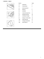
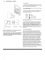
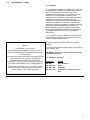
Please leave these instructions with the user
Baxi Belmont 2 &
Baxi Wentworth Classic
Fan Flue
Live Fuel Effect Inset Gas Fires
Comp No 244628 - Iss 5 - 2/00
Installation and
Servicing Instructions
Page 2
Natural Gas
BaxI Belmont 2 Fan Flue
G.C. No 32 075 23
BaxI Wentworth Classic Fan Flue
G.C. No 32075 14A
Baxi Limited is one of the leading manufacturers of
domestic heating products in the UK.
Our first priority is to give a high quality service to
our customers. Quality is built into every Baxi
product - products which fulfil the demands and
needs of customers, offering choice, efficiency and
reliability.
To keep ahead of changing trends, we have made
a commitment to develop new ideas using the
latest technology - with the aim of continuing to
make the products that customers want to buy.
Baxi is also the largest manufacturing partnership
in the country. Everyone who works at the
company has a commitment to quality because, as
shareholders, we know that satisfied customers
mean continued success.
We hope you get a satisfactory service from Baxi.
If not, please let us know.
Baxi is a BS-EN ISO 9001
Accredited Company
2
For use in GB / IE only.
Contents - Page 3
Section
Page
1.0
Introduction
4
2.0
Technical Data
6
3.0
Site Requirements
7
4.0
Electrical
9
5.0
Installation
11
6.0
Commissioning the Fire
21
7.0
Arranging the Coals
22
8.0
Checking for Spillage
25
9.0
Fitting the Trim & Fender
26
10.0
Annual Servicing
27
11.0
Changing Components
31
12.0
Short Parts List
37
3
1.0
Introduction - Page 4
1.1 Description
1. The Baxi Belmont 2 and Wentworth Classic Fan Flue are
live fuel effect inset gas fires designed to be used on Natural
Gas only at a setting pressure of 20 mbar.
2. The appliance is designed to give a maximum heat output
of 3.0 kW (10,236 Btu/h).
3. The fire is controlled by a knob which is positioned behind
the controls access door on the fender assembly (Fig. 1).
The knob has four positions:
Position
Position
Position
Off
Ignition
Minimum Output
Position
Maximum Output
4. The fan is controlled by the two rocker switches adjacent
to the control knob (Fig. 1).
5. A special feature of the Baxi Belmont 2 and Wentworth
Classic is the direct acting oxygen depletion system. This
system will shut down the appliance if there is inadequate
ventilation and the flue is not clearing the products of
combustion. Under no circumstances shall this device be
adjusted, bypassed or put out of action. The device must
be regularly serviced and strictly in accordance with these
instructions.
1.2 Important Information
NOTE: A red indicator (Fig. 1) shows when the electric
power is ON but the fan is not running.
The fire incorporates a fan so that it can be installed in a
room without a flue. The fan removes the products of
combustion horizontally through a flue duct which exits
at the rear of the appliance.
4
This product contains Refractory Ceramic Fibres (R.C.F.)
which are man-made vitreous silicate fibres. Excessive
exposure to these materials may cause temporary irritation
to eyes, skin and respiratory tract. Care must be taken when
handling these articles to ensure the release of dust or fibres
is kept to a minimum. To ensure that the release of fibres
from these articles is kept to a minimum, during installation
and servicing it is recommended that a H.E.P.A. filtered
vacuum is used to remove any dust, soot or other debris
accumulated in and around the appliance. This should be
performed before and after working on the installation, It is
recommended that any replaced item(s) are not broken up
but sealed within heavy duty polythene bags and clearly
labelled R.C.F. waste”. This is not classified as “hazardous
waste” and may be disposed of a tipping site licensed for the
disposal of industrial waste. Protective clothing is not
required when handling these articles but it is recommended
that gloves are worn and the normal hygiene rules of not
smoking, eating or drinking in the work area are followed and
always wash hands before eating or drinking.
1.0
Introduction - Page 5
1.3 Installation
1. The appliance is suitable for installation only in G.B. and
I.E. and should be installed in accordance with the rules in
force. For Ireland install in accordance with l.S.813
‘installation of Gas Appliances”. The installation must be
carried out by a Corgi Registered Installer or other
competent person and be in accordance with the relevant
requirements of Gas Safety (Installation and Use)
Regulations 1998 (as amended), the Building Regulations
issued by the Department of the Environment, Building
Standards (Scotland) (Consolidation) Regulations issued by
the Scottish Development Department and the Local
Building Regulations. Where no specific instructions are
given, reference should be made to the relevant BRITISH
STANDARD CODES OF PRACTICE and Installation
Specifications.
2. This appliance must be installed in accordance with the
manufacturers instructions and the rules in force and only
used in a suitably ventilated location.
3. Read the instructions before installing or using this
appliance.
Notice
Discolouration of wall surfaces
Most heating appliances generate warm air convection
currents and transfer heat to any wall surface against which
they are situated.
Some soft furnishings (such as blown vinyl wallpapers) may
not be suitable for use where they are subject to
temperatures above normal room levels and the
manufacturer’s advice should be sought before using this
type of wail coveting adjacent to any heating appliance.
The likelihood of wall staining from convected air currents
will be increased in environments where high levels of
tobacco smoke or other contaminants exist.
4. Ensure that all protective plastic coating is removed from
trim and fender parts.
IMPORTANT: Do not push excess electrical cable into
void behind the fender.
1.4 B.S. Codes of Practice
STANDARD
B.S. 6891
B.S. 5440: Pt 1
B.S. 5440: Pt 2
B.S. 5871: Pt 2
SCOPE
Gas Installation.
Flues.
Air Supply
Installation of inset live fuel effect
fires.
5
2.0
Technical Data - Page 6
Belmont 2 Fan Flue
Wentworth Classic Fan Flue
Category of Appliance
2H
The fire is set for Gas Type G20 at 20mbar.
Heat Input (net)
kW
Btu/h
High
6.16
21,018
Heat Output
kW
Btu/h
High
3.0
10,236
Inlet Setting Pressure
mbar
in wg
Terminal Position with Minimum Distance (Fiq. 17)
A
B
C
D
E
F
G
H
I
J
K
L
6
Directly below an openable window or other opening,
e.g. an air brick.
Below gutters, soil pipes or drain pipes.
Below eaves.
Below balconies or car port roof.
From vertical drain pipes and soil pipes.
From internal or external corners.
Above ground, roof or balcony level.
From a surface facing a terminal.
From a terminal facing a terminal.
Vertically from a terminal on the same wall.
Horizontally from a terminal on the same wall.
For an opening in a car port (e.g. door, window) into
a dwelling.
(mm)
300
75
200
200
75
300
300
600
1200
1500
300
1200
Min
2.4
8,200
Cold
20 ± 1.0
8 ± 0.4
Gas Connection
8mm OD tube, rigid or
semi rigid and 8mm
compression fitting at
appliance inlet
Controls &
Safety system
Rotary gas tap with direct
burner ignition, flame
failure device, direct
acting oxygen depletion
system and a fan on/off
switch with fan off
indication
Gas Rate
(after 10 mins)
0.65 m3/h
(23.0 ft3/h)
Lifting Weight
18.3 kg (40 Ibs)
Injector
Cat 127/440
Trim
Dimensions
Height 601 mm
Width 512 mm
Depth 125 mm
(from the wall)
Electricity
Supply
230 Volts
Fan supply
7
3.0
Site Requirements - Page 7
3.1 Location
1. The Baxi Belmont 2 and Wentworth Classic Fan Flue gas
fires must be installed on an outside wall. The maximum
distance from the rear face of the fire mounting frame to the
outside face of the wall is 600mm. The minimum is 300mm.
The effective wall thickness can be increased by the addition
of an internal fire surround.
2. The flue terminal must be located in a suitable position on
an outside wall taking into consideration the dimensions
shown in Fig. 3.
3.2 Ventilation
1. No purpose provided ventilation is normally required for
the appliance, normal adventitious room ventilation being
sufficient. Reference should be made to BS 5871 Part 2. For
Ireland refer to IS 813 Section 10 of the Irish Ventilation
Requirements.
3.3 Hearth Mounting
1. The fire is intended to be hearth mounted only. The
hearth must be of a non-combustible material at least 13mm
(½ in) thick and measuring at least 325mm (12 7/8 in) deep,
measured from the mounting wall face, by 580mm (22 27/32
in) wide. It must be fitted central to the fireplace opening.
The top surface of the hearth should be a minimum of 50mm
(2 in) above floor level (Fig. 4).
2. The fire must also stand on a non-combustible base
inside the fireplace opening, the same height as the hearth.
3. On no account should the fire unit be fitted directly onto a
combustible floor or carpet.
4. Alternatively, a fender rail or upstanding edge of 50mm
(2in) height can be fitted to the periphery of the 13mm (½ in)
non-combustible hearth (Fig. 5).
3.4 Purpose Built Hearths & Surrounds
1. Purpose built fire resistant hearths and back panels
specified as suitable by the manufacturer, or a suitable
propriety fire surround with 150º C rating may be used.
8
3.0
Site Requirements - Page 8
3.5 Clearances (Fig. 7)
1. Shelf Clearance - minimum clearance from the hearth to
the underside of a combustible shelf should be 830mm
(3221/32 in) provided the shelf depth is 150mm (529/32 in) or
less. When the shelf depth is increased by increments of
12.5mm (15/32 in) greater than 150mm (529/32 in), add 25mm
(1in) to the 830mm (3221/32 in).
2. Side of Fire - minimum width between vertical sides of a
combustible surround should not be less than 675mm (265/16
in) provided the fire is central to the surround and the sides
do not project forwards more than 150mm (529/32 in). For
every 12.5mm (½ in) that the projection of the sides is
increased by, add a further 50mm (2 in) to the inside width of
the surround. NOTE: When the fire is fitted, this gives a
minimum side clearance of 150mm (529/32 in).
3.6 Gas Supply & Connection
1. The gas supply is to be connected to the appliance as a
concealed fix from the rear.
Turn off any appliances that are fed by the meter and
isolate the gas supply by turning off at the meter.
2. It is advisable to route the supply to the left side of the
unit taking into account the requirements of BS 6891:1988
dealing with enclosed pipes.
3. It is necessary to remove the grommet from the left hand
hole in the fire back panel. The grommet must be cut in
order to accommodate the gas pipe and replaced as in Fig.
8. The pipe can then be routed to the inlet elbow. (Fig. 9)
4. A suitable isolating cock should always be fitted in the
supply feed to the fire to facilitate servicing.
9
4.0
Electrical - Page 9
4.1 Electrical Supply & Connection
1. All extemal wiring to the appliance must be in accordance
with the latest I.E.E. Wiring Regulations and any local
regulations that apply.
2. Ensure that any cables are not pulled tight and that it is
possible to isolate the electrical supply to the fire for
servicing.
3. In the event of an electrical fault after installation of the
appliance, preliminary electrical system checks must be
carried out i.e. earth continuity, short circuit, polarity and
resistance to earth.
4. Fuses used in this installation must be ASTA approved to
BS 1362.
5. The appliance must be earthed.
6. Any additional cable used should be 0.75 mm2 (24 x
0.2mm) PVC heat resistant as specified in table 16 of BS
6500.
7. Where the cable passes through brickwork or similar it
should be suitably protected and sealed.
8. This appliance requires a suitable 230 ~ 50Hz supply to
the fan box. The supply lead should be routed to a suitable
socket inside the house. If this lead is not long enough it may
be removed from the plug and a new cable fitted and wired
to a 3 A double pole isolating switch with a contact
separation of at least 3mm in both poles or to a 3 pin plug
which should also be fused at 3 A. This plug or isolating
switch should be readily accessible to the user to enable the
electrical supply to be switched off as required.
10
4.0
Electrical - Page 10
4.2 Schematic Wiring Diagram
11
5.0
Installation - Page 11
5.1 Initial Preparation
1. Unpack the appliance from the carton and check all items
are present. The ceramic coal bed items should be left in
their box until required.
2. Some sheet metal parts may be fitted with protective
plastic coating which must be removed prior to installation.
5.2 General Preparation
1. Make sure the chosen position will comply with the
installation requirements detailed in section 3.0 Site
Requirements.
2. Make sure the damp course and any electrical wiring or
piping in the wall is not affected by the installation.
3. Any gas supply pipe concealed in a wall, floor or cavity
must be continuous and enclosed in a gas tight sleeve. (Gas
Safety (Installation and Use) Regulations 1994 as
amended).
4. The fire can be fitted into a surround or false chimney
breast in front of a non-combustible wall, into a recess within
a brick, block or stone cavity wall, or into a timber framed
dwelling.
5.3 Preparation of the Site - Fire In front of the wall
1. This installation details the use of a fire surround or false
chimney breast having a minimum depth of 140mm. This will
allow the fire to be positioned in front of the wall with a hole
in the inner wall for the flue only. The maximum surround
depth will depend upon the wall thickness. The maximum
total depth is 600mm from the outer wall face to the rear face
of the outer fire frame. The minimum total depth is 300mm.
2. Any combustible material within the installation must be
at least 75mm away from the appliance, the flue box and the
circular horizontal flue.
3. A suitable liner should be made to enclose the fire
(Fig. 11). This should be fitted within the false fire surround.
It should be 24mm thick and be of Supalux or similar noncombustible board. If 24mm material is not available two or
more smaller boards may be used. It should extend from the
outer fire frame to the inside face of the wall. When fitted,
this box should be insulated to the top and sides with
100mm of Rockwool (Fig. 12).
12
5.0
Installation - Page 12
5.3 Preparation of the Site (cont)
4. Measure 400mm up from hearth level and mark this
dimension on the wall. Drill through the inner and outer walls
at the mark using a suitable pilot drill at a point
corresponding to the centre line of the fire flue outlet (Fig.
14).
5. From outside consider the position of the pilot hole in
relation to the brickwork. The fan box is 3 bricks high and
requires a cut-out in the wall 95mm above and 120mm
below the pilot hole. This cut-out must extend 100mm to the
left and 220mm to the right of the pilot hole (Fig. 13).
6. If the position of the fan box cut-out would be such that it
does not coincide with the brick courses the pilot hole
position can be re-marked 40mm up or down. The fan box
cut-out can then be marked relative to this new position.
7. If this is necessary the flue outlet on the rear of the fire
can be adjusted accordingly by undoing the six securing
screws. It may be necessary to remove the flue outlet plate
and fit it the other way up to achieve the desired ammount of
adjustment. Precise adjustment of the flue height can be
carried out when the flue duct is fitted.
8. Cut a hole 100mm diameter in the inner wall at the
required height for the flue duct.
9. A separate hole approximately 35mm diameter should be
made through the inner wall towards the bottom right hand
corner of the fire location to enable the electrical cables to
pass through the wall and connect the fire to the fan box and
allow for the 230V supply cable to the fan box.
10. From outside cut a neat rectangular hole for the fan box
assembly. The cavity should be sealed where the flue duct
will pass through. Use Rockwool or similar to each side of
the opening to a thickness of at least 100mm.
Proceed to section 5.5 Fitting the Fan Box
13
5.0
Installation - Page 13
5.4 Preparation of the Site - Fire fitted Into a recess
1. A suitable liner should be made to enclose the fire (Fig.
16). This should be fitted within the false fire surround. It
should be 24mm thick and be of Supalux or similar noncombustible board.
If 24mm material is not available two or more smaller boards
may be used. It should extend from the front of the fire
mounting face to the inside face of the outside wall. The
outside of this box should be insulated to the top and sides
with 100mm of Rockwool when the box passes through the
cavity between the inner and outer walls.
2. A hole 100mm diameter must be cut centrally in the rear
panel of the liner for the flue duct. The height of the hole
should be the height at which the pilot hole is to be drilled, or
at its’ adjusted position-see paragraph 4 to 7 below and
Fig. 14. Also a hole approximately 35mm diameter should be
cut in the lower right of the liner to accept the electrical
cables.
3. Mark the position of the recess to be cut for the fire on the
inside wall.
N.B. A lintel may be required above the cavity for the fire. If
in doubt seek expert building advice.
4. Cut the cavity in the inner wall for the fire. Measure
400mm up from hearth level and mark this dimension
centrally on the inner face of the outer wall. Drill through
outer wall at the mark using a suitable pilot drill.
5. Consider the position of the pilot hole in relation to the
brickwork. The fan box is 3 bricks high and requires a cut-out
in the wall 95mm above and 120mm below the pilot hole.
This cut-out must extend 100mm to the left and 220mm to
the right of the pilot hole.
6. If the position of the fan box cut-out would be such that it
does not coincide with the brick courses the pilot hole
position can be re-marked 40mm up or down. The fan box
cut-out can then be marked relative to this new position.
7. If this is necessary the flue outlet on the rear of the fire
can be adjusted accordingly by undoing the six securing
screws. it may be necessary to remove the flue outlet plate
and fit it the other way up to achieve the desired ammount of
adjustment. Precise adjustment of the flue height can be
carried out when the flue duct is fitted.
8. From outside cut a neat rectangular hole for the fan box
assembly.
Proceed to section 5.5 Fitting the Fan Box
14
5.0
Installation - Page 14
5.4 Preparation of the Site - Timber Frame Dwelling
9. This installation requires a 150mm diameter piece of
single wall flue pipe or similar for use as a metal sleeve
(Fig. 19).
10. This installation details the use of a fire surround or false
chimney breast, having a minimum depth of 140mm, which
allows the fire to be positioned in front of the wall with a hole
in the inner wall for the flue only. The maximum surround
depth will depend upon the wall thickness. The maximum
total depth is 600mm from the outer wall face to the rear face
of the outer fire frame. The minimum total depth is 300mm.
11. Any combustible material within the installation must be
at least 75mm away from the appliance, the flue box and the
circular horizontal flue.
12. Installation must be in accordance with the current
edition of Institute of Gas Engineers Publication IGE/UP/7
(Gas Installations in Timber Framed Housing).
13. A suitable liner should be made to enclose the fire. This
should be fitted within the false fire surround. It should be
24mm thick and be of Supalux or similar non-combustible
board. If 24mm material is not available two or more smaller
boards may be used. It should extend from the outer fire
frame to the inside face of the wall. When fitted, this box
should be insulated to the top and sides with 100mm of
Rockwool.
14. The back surface of the fire must be separated
from the timber frame by 25mm of non-combustible material.
This can consist of the usual 13mm plasterboard wall lining
plus 12mm of Supalux or similar non-combustible board.
15. Measure 400mm up from hearth level and mark this
dimension on the wall. Drill through the inner and outer walls
at the mark using a suitable pilot drill, centrally in any
surround.
15
5.0
Installation - Page 15
5.4 Preparation of the Site (cont)
16. Taking into consideration the dimensions in fig.13 and 14
on page 12 and the position of the pilot hole, cut a suitable
hole for the flue box assmebly.
17. Once the height of the flue has been determined make a
hole through the wall to accept a 150mm diameter sleeve.
Ensure that when the 150mm diameter hole is cut through
the wall and the rectangular recess is cut in the outer wall,
no timbers are cut.
18. Make sure that the vapour barrier is cut carefully and
made good to maintain its integrity.
19. A separate hole should be made towards the bottom
Right Hand corner of the fire location to enable the electric
cables to pass through the wall and connect the fire to the
flue box and allow for the 230V supply cable to the fan box.
20. The cavity should be sealed where the flue box hole has
been cut. Rockwool or equivalent may be used, it should be
fitted above and to each side of the opening to a thickness of
at least 100mm.
21. A sloping plate should be fitted above the 150mm
diameter sleeve in accordance with IGE Publications DM2
Section 6.1.5 (b).
22. Measure the length required for a 150mm diameter metal
wall sleeve, which should fit between the inside wall face
and the inside of the outer wall or the rear of the fan box,
which ever is the closer to the fire. Cut to length and fit into
the 150mm diameter hole. Seal any gaps with a suitable
sealant at each end.
Proceed to section 5.5 Fitting the Fan Box
16
5.0
Installation - Page 16
5.5 Fitting the Fan Box
1. Place the power supply cable and fan to fire harness in
their intended positions, passing through the hole in the wall
where applicable.
2. Either fit the liner into the recess and pass the fan to fire
harness through the hole in the liner, or complete the false
chimney breast or surround incorporating the liner as
appropriate.
3. Unpack the fan box assembly and undo the screws
retaining the brown fan box cover. Take the loose sponge
seal from the fan box (Fig. 21).
4. Taking note which is the top, undo the screws securing
the fan box to the fan box collar. Slide the collar into the wall
(Fig. 20), mark the fixing holes and remove. Below each
collar fixing hole also drill a 10mm diameter recess to accept
the threaded bushes in the collar.
5. Drill and plug the holes and refit the collar using suitable
screws. Any gaps around the edges should be sealed (Fig.
20).
6. Fit the larger diameter flue duct to the rear bayonet fixing
on the fan box ensuring it is located correctly and the seal is
made (Fig. 21). Depending upon the wall thickness it may be
necessary to cut the flue - see Section 5.6.
7. Fit the sponge seal to the 2 sides and top of the fan box
mounting face (Fig. 21).
8. Remove the sensing tube from the fan. Undo the screws
holding the pressure switch bracket to the fan box. Pull the
bracket and switch from the box (Fig. 21).
9. Undo the two screws securing the fan control unit bracket
to the fan box and draw the bracket forwards (Fig. 22).
10. Remove the grommet from the slot in the cut-out at the
top right of the fan box. Cut the grommet and lit it over the
power supply cable.
11. Connect the 3 pin plug to the socket on the fan control
unit bracket and re-fit the grommet into slot (Fig. 22).
12. Fit the fan control unit bracket to the fan box using the
two screws previously removed.
13. Connect the 8-pin plug from the fan box (Fig. 22) to the
8-pin socket on the harness. Connect the earth lead to the
screw on the rear face of the fan box.
17
5.0
Installation - Page 17
5.5 Fitting the Fan Box (cont)
14. Locate the fan box and flue assembly in the flue box
collar and secure with the screws previously removed and
refit the pressure switch bracket (Fig. 23). Reconnect the
sensing tube (Fig. 24).
15. Fit the fan box cover to the fan box assembly. A
TERMINAL GUARD IS RECOMMENDED Baxi Heating Part
No 245770. Position the guard over the fan box. Ensure the
guard is equally spaced about the fan box. Mark the fixing
positions, drill and plug the holes and secure the guard to
wall (Fig. 24).
18
5.0
Installation - Page 18
5.6 Fitting the Fire
1. There are 2 methods of fixing the fire in position, using
the eyebolts and cables or simply screwing through the outer
fire frame with 4 screws to the wall or surround face.
NOTE: It is recommended that the appliance is screwed
to the wall or surround face. The eyebolt and cable
method can only be used when the appliance is installed
in a false chimney breast or surround.
2. Either mark the wall as shown (Fig. 26) and drill, plug and
fit the 4 eyebolts (Fig. 25) or mark the front face of the
surround using the fire as a template and drill and plug the 4
holes, 2 at each side. The top 3 holes may also be used if
required to ensure a good seal between the fire and the
surround (Fig. 27).
3. With the gas supply routed from the rear, mark as shown
(Fig. 26) and install the pipework after considering section
3.6 Gas Supply and Connections.
4. Take the foam seal from the kit and remove its backing
strip. Fit it to the rear of the fire frame (Fig. 27).
5. Measure the space between the front wall fixing face and
the outside wall. Check that the telescopic flue can be set at
the appropriate length. Each of the flue ducts may be
reduced in length to allow short flues. The overlap must be
maintained at a minimum of 30mm.
6. If the wall thickness is at the minimum (300 mm) both flue
ducts must be cut to 65mm.
7. Fit the smaller diameter flue duct to the fire outlet,
ensuring it is located correctly and the seal is made.
8. Undo the 3 screws retaining the burner chassis to the
combustion box sides and base. Withdraw the chassis and
place to one side (Fig. 27).
9. Remove and cut the left hand side grommet to accept the
gas supply (Fig. 27).
19
5.0
Installation - Page 19
5.6 Fitting the Fire (cont)
SCREW FIXING METHOD
1. Fit the fan box harness lead through the hole at the right
hand side of the fire. Do not draw any more of the harness
into the fire than is necessary.
2. Position the appliance in front of the fireplace opening.
Manoeuvre the appliance backwards into the opening (Fig.
28).
3. Secure the fire in position using suitable screws in the
previously drilled and plugged holes.
4. Fit the gas inlet/pressure test point elbow supplied in the
kit to the controls feed pipe (Fig. 28a). Connect the 8-way
plug to the controls and secure the earth lead to the earth
post on the fire. Connect the gas supply to the gas
inlet/pressure test point elbow and refit the burner chassis
(Fig. 28b).
20
5.0
Installation - Page 20
5.6 Fitting the Fire (cont)
CABLE TENSION METHOD OF FIXING
1. Engage the tensioning nuts on the threaded shanks of
the tensioning devices. Run the nuts down to the hexagonal
heads of the tensioning devices (Fig. 29).
2. From the front insert the cable tensioning devices through
the combustion box rear panel. The hexagonal heads must
be to the inside of the box (Fig. 29).
3. Fit the fan box harness through the hole at the right hand
side of the fire. Do not draw any more of the harness into the
fire than is necessary.
4. Position the appliance in front of the fireplace opening
and insert the cables in the holes in the combustion box rear
flange (Fig. 30). Pass the cables through the eyebolts in the
fire opening rear face and insert them in the tensioning
devices (Fig. 29 & 30). Manouvre the appliance backwards
into the opening, drawing any slack length of cable through
the tensioners.
5. Push the appliance as far back in the opening as possible
and pull the cables through the tensioners as tight as
possible.
6. Run the solderless nipples down the cables to the
tensioners and tighten their securing screws (Fig. 29). As
required, take the relevant grommet(s) and slide over the
gas and/or electrical supplies. Run the grommet(s) down the
pipe and/or cable and insert in the hole in the rear panel
(Fig. 31).
7. Using a suitable spanner tighten the tensioning nuts
clockwise so that the fire frame surround is pulled up against
the wall or surround and the seal is compressed. DO NOT
CUT OFF THE EXCESS CABLE - coil neatly and secure
with tape.
8. Fit the gas inlet/pressure test point elbow supplied in the
kit to the controls feed pipe (Fig. 31a). Connect the 8-way
plug to the controls and secure the earth lead to the earth
post on the fire. Connect the gas supply to the gas
inlet/pressure test point elbow and refit the burner chassis
(Fig. 31).
21
6.0
Commissioning the Fire - Page 21
6.1 Checking Gas Soundness
1. Turn on the gas supply and check for gas soundness with
leak detection fluid (BS 6891).
6.2 Checking OperatIon of the Fire
1. Turn off the gas supply. Remove the screw from the
pressure test point on the gas inlet elbow and connect a
suitable pressure gauge (Fig. 32).
2. Check that the electrode is sparking to the burner (Fig.
33) when the control knob is pushed in and rotated
anticlockwise past the ignition position ( ) (Fig. 35).
3. Re-set the appliance to the OFF position ( ) and turn on
the gas and electrical supplies to the appliance.
6.3 Lighting the Fire
1. Press the spring loaded fan ON switch to start the fan.
The switch will return to its’ original position when released.
The red indicator light will go out when the air pressure
switch has proven the fan is running
2. Purge the air from the appliance by depressing the
control knob and rotating slowly anticlockwise through the
ignition position ( ). When the electrode sparks the burner
will light.
3. Once the burner has lit continue to push in the control
knob for 15 seconds allowing the magnetic safety valve to
operate.
4. If the burner fails to light repeat step 2 and 3 above.
5. With the burner alight, depress the control knob slightly
and rotate anticlockwise to the maximum output position ( )
(Fig. 37).
6. Release the knob and check the gas inlet pressure is 20
mbar ± 1.0 mbar.
7. Turn the control knob back to the OFF ( ) position (Fig.
34). Disconnect the pressure gauge and re-fit the screw to
the pressure test point ensuring a gas tight seal.
8. Press the OFF switch to turn the fan off. The switch will
return to its’ original position when released.
22
7.0
Arranging the Coals - Page 23
7.1 Identification
It is Important that all the firebed components are used
and arranged as shown In order to achieve the desired
flame picture. Ensure all firebed components are
present and Identified prior to Installation.
1. Remove the coals, and front and rear coal mouldings
from their packaging and place them on a newspaper or
similar to prevent soiling furnishings.
CAUTION: The coals are extremely fragile and must be
handled accordingly. To avoid soiling ones hands,
gloves should be worn and any inhalation of the dust
should be avoided. Keep the coals away from children at
all times. Never use coals other than those supplied or
Genuine Baxi Spare Parts. Never put additional coals on
the fire. Please read Section 1.2 Important Information
2. The side and back brick effect insulation panels can be
reversed to offer a plain effect for the customer. To reverse
this brick effect remove the left and right hand black sheet
metal retaining pieces. Carefully remove the three insulation
panels and reassemble with the plain effect on display. Refit
the retaining panels taking care not to damage the paint and
insulation panels.
23
7.0
Arranging the Coals - Page 23
7.2 Arranging the Coalbed
NOTE: It is important for the safe operation of the
appliance that the front and rear coal mouldings are
correctly located and in accordance with these
instructions.
1. Carefully position the rear coal moulding into the rear of
the fire. The undercut in the base of the moulding should rest
on the tabs of the rear coal support. The back face of the
moulding should sit on the rear coal support. Care should be
taken that the rear coal moulding does not fall forward at this
stage.
2. Carefully position the front coal moulding on the burner
tray with the front edge of the moulding behind the lip. The
rear edge of the moulding should then rest on the front of the
burner (Fig. 39).
24
7.0
Arranging the Coals - Page 24
7.3 Arranging the Loose Coals
NOTE: Do not allow any of the coals to fall into the gap
between the front and rear coal mouldings.
1. Take 2 coals and place on the outer edges of the front
coal moulding (Fig. 40).
2. Take 4 coals and place as shown in Fig. 41 bridging the
front and the rear coal mouldings. Ensure that the flat faces
on these coals face downward.
3. Take the 5 remaining coals and place as shown in Fig. 42
positioned in the gaps between the coal mouldings and
loose coals.
25
8.0
Checking for Spillage - Page 25
8.1 Checking for Spillage
CAUTION-Whilst checking for spillage care must be
taken to avoid touching hot panels.
1. Before starting the test close all doors and windows.
2. Operate the fire from cold at maximum input.
3. After approximately five minutes check for spillage.
4. Fit a smoke match into a holder, and position with the
holder held horizontally projecting 20mm under the lip of the
canopy bottom and 70mm from the start of the straight
section on one side of the fire (Fig. 43 & 44).
5. If spillage is evident leave the fire operating for a further
ten minutes and repeat test.
6. If test is successful repeat with any extractor fan
operating and connecting doors open to create the worst
likely operating conditions.
7. If spillage still occurs and the problem cannot be rectified
the fire must be isolated until the problem is resolved.
NOTE: It is important that the smoke match is
positioned accurately for the test as an incorrectly
positioned match may result in smoke being picked up
by convected air currents, indicating spillage.
26
9.0
Fitting the Trim & Fender - Page 26
9.1 Fitting the Trim and Fender (Fig. 45)
1. Carefully remove the trim and fender from their
packaging.
2. Align the trim with the fire outer frame. The trim has four
keyhole type cutouts on the inside edge which locate on the
tabs on the black side trims.
3. Place the fender assembly centrally between the legs of
the trim and push it back as far as possible.
4. In a similar manner place the controls access door
centrally in the fender opening and push back as far as
possible.
9.2 Informing the User
1. These instructions and the Users Operating Instructions
should be handed to the customer. At the same time the
customer should be shown how to operate the fire safely and
efficiently.
2. The need for annual servicing should be emphasised and
the returning of the guarantee card advised.
27
10.0 Annual Servicing - Page 27
10.1 Maintenance
IMPORTANT: It is possible that some soot may be
deposited on the coals after use. This is acceptable
providing it is not allowed to accumulate.
CAUTION: The coals are extremely fragile and must be
handled accordingly. To avoid soiling ones hands,
gloves should be worn and any inhalation of the dust
should be avoided. Keep the coals away from children at
all times. Never use coals other than those supplied or
Genuine Baxi Spare Parts. Never put additional coals on
the fire. Please read Section 1.2 Important Information
1. Servicing should be carried out regularly by a competent
person in accordance with the relevant regulations, to
ensure the safe and correct operation of the appliance.
2. Before commencing any service or replacement of parts,
turn off the gas supply to the fire and ensure that the fire is
cold, and isolate the electrical supply.
3. After servicing, check for gas soundness.
4. When ordering spare parts please quote appliance name
and serial number. These can be found on the data badge
which is located by removing the controls access door, the
badge is on the base plate of the appliance.
5. If excessive soot has accumulated check to establish the
cause.
6. The loose coals may be removed for cleaning. The coals
are delicate and should be handled carefully. Gently brush
with a soft brush to remove dust or deposts.
7. Examine the coals for signs of cracking and replace if
necessary.
IMPORTANT: See coal layout procedure (Section 7.0
Arranging the Coals) before attempting to replace coals
which should only be replaced as a complete set with no
extra coals added.
28
10.0
Annual Servicing - Page 28
10.2 Preparation
1. For reasons of safety and economy it is important to
service the fire annually.
WARNING: Isolate the gas and electrical supplies to the
appliance before servicing.
2. Remove the controls access door and fender assembly
(Fig. 46).
3. Remove the trim (Fig. 46).
4. Carefully remove all the loose coals, and the front and
rear coal mouldings (Fig. 47).
5. Undo the gas supply at the disconnecting union. If
necessary remove any pipework between the union and inlet
elbow (Fig. 48).
6. Undo the three screws retaining the burner and controls
to the combustion box sides and combustion box base.
Withdraw the burner and controls from the fire (Fig. 49).
29
10.0
Annual Servicing - Page 29
10.3 Cleaning the Burner and Injectors
1. Undo the screw retaining the spark electrode to the
burner tray (Fig. 50).
2. Undo the screw retaining the burner to the burner tray
(Fig. 51).
3. Slide the burner to the left to disengage from the injector.
Rotate the electrode slightly and lift the burner out of the
tray.
4. Using a soft brush remove any dirt from the burner and
ensure all ports are free from obstruction.
5. Undo the union nut connecting the gas pipe to the injector
(Fig. 50).
6. Undo the injector locknut and remove the injector from
the burner tray by disengaging the gas pipe from the injector
(Fig. 52).
7. Examine and clean the injector. Do not use any hard
tools such as pins or wire. Renew if necessary (Fig. 52).
8. When retightening the gas feed pipe nut, hold the injector
body with a suitable spanner to prevent misalignment of the
injector.
9. Reassemble in reverse order.
10.4 Cleaning the Thermocouple (Fig. 53)
NOTE: No attempt should be made to clean the device
using any hard tools, including pins or wire.
WARNING: The thermocouple assembly must not be
adjusted in any way, or be altered so that it will not
operate or be bypassed.
1. Ensure that the burner aeration hole is free from lint,
debris etc.
2. Ensure that the thermocouple locknut is tight and there is
no damage to the thermocouple lead.
3. The thermocouple can be changed as an individual
component. (See section 11.0 Changing Components).
4. Only use a Genuine Baxi Spare Part.
30
10.0
Annual Servicing - Page 30
10.5 Cleaning the Electrode (Figs. 54 & 55)
1. Check for any signs of cracking or other damage to the
ceramic.
2. Clean the electrode wire if necessary.
3. Upon re-assembly check the spark gap is 2.5-4.0mm.
10.6 Cleaning the Fan
1. From outside remove the terminal guard and fan box
cover (Fig. 57).
2. Undo the screws holding the fan outlet plenum to the fan
box. Manouvre the plenum from the box taking care not to
damage the rear gasket (Fig. 56). Note the position of the
three wires to the fan and remove them. Disconnect the
sensing tube from the fan (Fig. 58).
3. Rotate the complete fan approximately 20º anti-clockwise
to disengage it from the fan box. Draw the fan clear of the
box (Fig. 58).
4. Ensure the flue duct is clean and free from debris.
5. Carefully clean any deposits from the fan impellor with a
soft brush.
6. When reassembling ensure that the rear gasket is in
position behind the flue outlet plenum.
10.7 Completing Servicing
1. Clean any dirt and debris from the appliance combustion
box and installation.
2. Reassemble all components in reverse order of
dismantling and recommission the fire.
31
11.0 Changing Components - Page 31
11.1 Changing Components
WARNING: Isolate the gas and electrical supplies to the
appliance before changing any components.
1. Remove the controls access door and fender assembly
(Fig 59).
2. Carefully remove all the loose coals and the front and
rear coal mouldings.
CAUTION: The coals are extremely fragile and must be
handled accordingly. To avoid soiling ones hands,
gloves should be worn and any inhalation of the dust
should be avoided. Keep the coals away from children at
all times. Never use coals other than those supplied or
Genuine Baxi Spare Parts. Never put additional coals on
the fire. Please read section 1.2 Important Information
NOTE: After changing any components carry out checks
for gas soundness
1. Pull and lift the trim away from the fire outer frame. It is
attatched by the keyways in the inside edge of the trim.
32
11.0
Changing Components - Page 31
11.2 Removal of Controls / Burner Chassis Assembly
1. If any of the controls components are to be renewed the
burner chassis assembly must be removed from the
appliance.
2. Undo the gas supply at the disconnecting union. If
necessary remove any pipework between the union and inlet
elbow (Fig. 60).
3. Undo the three screws retaining the burner chassis
assembly to the combustion box sides and combustion box
base. Withdraw the burner chassis assembly (Fig. 61).
11.3 Burner
1. Undo the screw retaining the spark electrode to the
burner tray (Fig. 62).
2. Undo the screw retaining the burner to the burner tray
(Fig. 63).
3. Slide the burner to the left to disengage from the injector.
Rotate the electrode and lift clear
4. Replace with new burner and re-assemble in reverse
order.
11.4 Injector (Fig. 64)
1. Remove the burner as described in 11.3 and undo the
union nut connecting the gas feed pipe to the injector (Fig.
62).
2. Remove the locknut retaining the injector to the controls
frame and withdraw the injector by disengaging the gas pipe
from the injector.
3. Fit the new injector. When retightening the gas feed pipe
nut, hold the injector body with a suitable spanner to prevent
misalignment of the injector.
4. Reassemble in reverse order.
33
11.0
Changing Components - Page 33
11.5 Electrode (Fig. 65)
1. Disconnect the electrode lead from the tag at the base of
the electrode.
2. Undo the screw retaining the electrode to the burner tray
and withdraw.
3. Fit the new electrode and re-assemble in reverse order.
Check that the spark gap is between 2.5mm and 4.0mm.
11.6 Thermocouple
1. Remove the burner as described in section 11.3.
2. Undo and remove the locknut holding the thermocouple
to the burner tray (Fig. 66).
3. Undo the thermocouple nut from the rear of the gas valve
(Fig. 67) and remove the thermocouple from the burner tray.
4. Carefully bend the new thermocouple to the shape of the
original and reassemble in reverse order of dismantling.
34
11.0
Changing Components - Page 34
11.7 Gas Tap and Piezo Unit (Fig. 69)
1. Remove the burner as described in section 11.3.
2. Undo the thermocouple nut from the rear of the gas
valve.
3. Undo the union nuts connecting the gas inlet pipe and the
gas feed pipe to the injector from the body of the gas valve.
4. Disconnect the electrode lead from the piezo unit.
5. Pull away the control knob (Fig. 68) from the gas valve
shaft.
6. Undo the two screws retaining the gas valve and piezo
unit to the control marking plate and remove the unit.
7. Fit the new unit and reassemble in reverse order.
11.8 Electro-Magnetic Unit (Fig. 69)
1. Undo the thermocouple nut from base of the tap.
2. Undo the magnetic unit retaining nut and withdraw the
magnetic unit.
3. Fit the new magnetic unit and reassemble in reverse
order.
35
11.0
Changing Components - Page 35
11.9 Fan (Fig. 70 & 71)
1. From outside remove the terminal guard and fan box
cover.
2. Undo the screw holding the fan outlet plenum to the fan
box. Manouvro the plenum from the box taking care not to
damage the rear gasket (Fig. 70a). Note the position of the
three wires to the fan and remove them. Disconnect the
sensing tube from the fan.
3. Rotate the complete fan approximately 20º anti-clockwise
to disengage it from the fan box. Lift the fan clear of the box.
4. Fit the new fan and reassemble in reverse order. When
reassembling, ensure that the rear gasket is in position
behind the plenum.
11.10
Air Pressure Switch (Fig. 72)
1. From outside remove the fan box cover, 4 screws.
2. Remove the sensing tube from the fan. Undo the screws
holding the pressure switch bracket to the fan box. Pull the
bracket and switch from the box.
3. Note the position of the three wires to the pressure switch
and remove them. Undo the two screws retaining the switch
to the bracket and remove the switch.
4. Fit the new switch and connect the wires and sensing
tube as previously noted.
11.11
SolenoId Valve (Fig. 73)
1. Remove the plug connecting the solenoid valve, noting
the position of the solenoid valve.
2. Undo the two union joints, one at each side of the valve
and remove the valve.
3. Renew the valve and reassemble in reverse order
ensuring it is fitted the correct way round and in the same
orientation as the original.
36
11.0
Changing Components - Page 36
11.12
Fan Control Unit
1. From outside remove the terminal guard and fan box
cover (Fig. 74).
2. Undo the four screws holding the fan box to the fan box
collar and draw the fan box out. Disconnect the 8-way plug
and undo the earth screw from the rear of the fan box.
Completely remove the fan box from the wall.
3. Undo the screws securing the pressure switch bracket to
the fan box and draw the bracket forwards (Fig. 75).
4. Pull the sensing tube off the fan. Note the position of the
wires on the fan and pressure switch and remove them.
Place the pressure switch to one side (Fig. 75).
5. Undo the screws securing the fan control unit bracket to
the fan box. Disconnect the 3-pin plug and socket and draw
the bracket forwards (Fig. 76).
6. Undo the earth screw from the bracket and remove the
screws retaining the plug and fan control unit to the bracket
(Figs. 76 & 77).
7. Fit the new fan control unit (Fig. 77) and reassembly in
reverse order.
37
12.0 Short parts list - Page 37
12.1 Short Parts List
Click here for Helplines
38
Manufacturers
Part No.
Key
No.
G.C.
No.
Description
40
E25 213
Front Coal Moulding
245256
41
E25 214
Rear Coal Moulding
245257
44
E25 217
Loose Coals
245260
22
E25 198
Control Knob
245239
23
E25 199
Gas Tap
245240
24
E01 617
Mag Unit
239413
29
E01 353
Piezo Unit
239289
26
378 924
Electrode Lead
236493
30
E25 203
HT Sleeve
245247
19
E25 196
Injector
245237
12
E24 110
Burner
245229
25
E25 200
Electrode
245242
27
E25 201
Thermocouple
245244
48
E25 221
Fan
245261
51
E25 223
Fan Control Box Unit
245263
49
E25 222
Air Pressure Switch
245262
53
E25 266
Solenoid valve
245265