1
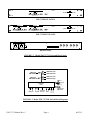
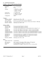
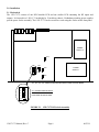
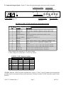
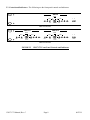
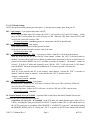
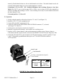
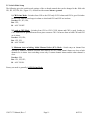
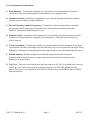
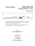
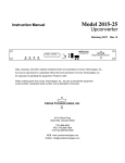
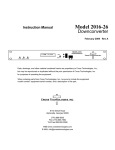
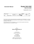
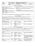
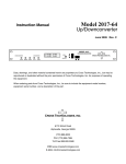
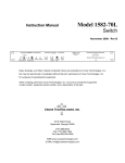
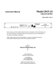
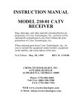
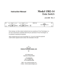
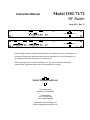
Model 1582-71/72
Instruction Manual
RF Switch
June 2011 Rev. C
MODEL 1582
SWITCH
SWITCH
AUTO
CH 1
CH 2
MAN ALM ON- MANUAL ON- ALM REM RESET
LINE SELECT LINE
SWITCH A
2
CROSS TECHNOLOGIES, INC.
POWER
SWITCH B
AUTO
CH 1
1
MODEL 1582
SWITCH
AUTO
CH 2
CH 1
CH 2
1
2
CROSS TECHNOLOGIES, INC.
MAN ALM ON- MANUAL ON- ALM REM RESET
LINE SELECT LINE
MAN ALM ON- MANUAL ON- ALM REM RESET
LINE SELECT LINE
POWER
Data, drawings, and other material contained herein are proprietary to Cross Technologies, Inc.,
but may be reproduced or duplicated without the prior permission of Cross Technologies, Inc.
for purposes of operating the equipment. Printed in USA.
When ordering parts from Cross Technologies, Inc., be sure to include the equipment
model number, equipment serial number, and a description of the part.
CROSS TECHNOLOGIES, INC.
6170 Shiloh Road
Alpharetta, Georgia 30005
(770) 886-8005
FAX (770) 886-7964
Toll Free 888-900-5588
WEB www.crosstechnologies.com
E-MAIL [email protected]
INSTRUCTION MANUAL
MODEL 1582-71/72 RF Switch
TABLE OF CONTENTS
Warranty
1.0 General
1.1 Equipment Description
1.2 Technical Characteristics
2.0 Installation
2.1 Mechanical
2.2 Input and Output Signals
2.3 Controls and Indicators
2.4 Operation
2.5 Switch Mode Setup
3.0 Environmental Use Information
PAGE
2
3
3
5
6
6
7
7
9
10
11
WARRANTY - The following warranty applies to all Cross Technologies, Inc. products.
All Cross Technologies, Inc. products are warranted against defective materials and
workmanship for a period of one year after shipment to customer. Cross Technologies,
Inc.’s obligation under this warranty is limited to repairing or, at Cross Technologies,
Inc.’s option, replacing parts, subassemblies, or entire assemblies. Cross Technologies,
Inc. shall not be liable for any special, indirect, or consequential damages. This warranty
does not cover parts or equipment which have been subject to misuse, negligence, or
accident by the customer during use. All shipping costs for warranty repairs will be
prepaid by the customer. There are not other warranties, express or implied, except as
stated herein.
CROSS TECHNOLOGIES, INC.
6170 Shiloh Road
Alpharetta, Georgia 30005
(770) 886-8005
FAX (770) 886-7964
Toll Free 888-900-5588
WEB www.crosstechnologies.com
E-MAIL [email protected]
1582-71/72 Manual, Rev. C
Page 2
06/23/11
MODEL 1582-71/72 RF Switch
1.0 General
1.1 Equipment Description
The 1582-71 provides Auto, Manual or Remote relay switching between CH1 and CH2 RF signals. Alarm
conditions on CH1 and CH2 are either a contact closure to ground or an open (selectable). The logic controls
two separate RF switches, X and Y. The 1582-72 has two independent switches. Switching logic can be
selected as follows:
1) CH1 Prime Mode - Switches from CH1 to the CH2 only if CH1 alarms and CH2 is good. Switches back
when CH1 no longer in alarm or both CH1 and CH2 are bad.
2) Latch to CH2 Mode - Switches to CH2 if CH1 alarms and CH2 is good. Latches to CH2. Push Manual
Reset or ground Remote Reset pin to return to CH1 if it has no alarm.
3) Minimum AUTO switching, Initial Channel Select ( ICS) Mode- Switch stays on channel last selected by
Manual or Remote selection after return to AUTO. AUTO switching occurs only if current channel alarms and
other channel clear.
When power is lost and on power up (as alarms at power up dictate), channel 1 is selected. The Manual Select
switch and (when in AUTO) contact closures to Remote Select pins, select CH1 or CH2 independent of
alarms. LEDs indicate alarms. LEDs and closures to ground indicate switch conditions for CH1, CH2 and
REMOTE or MANUAL operation. Redundant power supplies
1582-71/72 Manual, Rev. C
Page 3
06/23/11
MODEL 1582
SWITCH
SWITCH
AUTO
CH 1
1
CH 2
MAN ALM ON- MANUAL ON- ALM REM RESET
LINE SELECT LINE
2
CROSS TECHNOLOGIES, INC.
POWER
1582-71 FRONT PANEL
SWITCH A
SWITCH B
AUTO
CH 1
MODEL 1582
SWITCH
AUTO
CH 2
CH 1
CH 2
1
2
CROSS TECHNOLOGIES, INC.
MAN ALM ON- MANUAL ON- ALM REM RESET
LINE SELECT LINE
MAN ALM ON- MANUAL ON- ALM REM RESET
LINE SELECT LINE
POWER
1582-72 FRONT PANEL
AC1
AC2
B1
B
B2
A1
A
A2
J1
J2
J3
J4
J5
J6
GND
1
J7
14
REAR PANEL
FIGURE 1.1 Model 1582-71/72 Front and Rear Panels
SWITCH B1 (RF)
SWITCH B
SWITCHED RF
SWITCH B2 (RF)
SWITCH A1 (RF)
SWITCH A
SWITCHED RF
SWITCH A2 (RF)
CH 1
AUTO
CONTROL
LOGIC
1
2
REMOTE
1 2 REMOTE 1 2
ALARM SW. RST MON
CH 2
M R
A E
N M
SWITCH
RESET
FIGURE 1.2 Model 1582-71/72 RF Switch Block Diagrams
1582-71/72 Manual, Rev. C
Page 4
06/23/11
1.2 Technical Characteristics
TABLE 1.1 1582-71/72 RF Switch Specifications*
Switch Characteristics
Impedance
Type
Isolation
Switch Time
Insertion Loss
Configuration
75 , 50 optional
Relay
> 65 dB, DC to 10 MHz
> 50 dB, to 1.0 GHz
> 40 dB, to 1.5 GHz
10 milliseconds
1 dB, DC to 1.0 GHz
1.5 dB, to 2.0 GHz
DPDT
Controls
MANUAL SELECT
SWITCH RESET
HISTORY RESET
MANUAL SELECT
Manually select CH1 or CH2
Resets to CH1 in latch mode, and resets REMOTE
Resets alarm history (prior occurrence of alarms now cleared) - LEDs only
Manually select CH1 or CH2
Indicator LEDs
CH1 ON-LINE
CH2 ON-LINE
MANUAL
ALARM CH1
ALARM CH2
ALARM HISTORY 1
ALARM HISTORY 2
POWER CH1
POWER CH2
REMOTE
MANUAL SELECT
Turns green when Channel 1 is selected
Turns green when Channel 2 is selected
Turns red when the Manual Select switch manually selects channel 1 or 2.
Turns red when Channel 1 alarm input is a closure or open (selectable)
Turns red when Channel 2 alarm input is a closure or open (selectable)
Turns red on Channel 1 alarm and stays red until HISTORY RESET is pushed
Turns red on Channel 2 alarm and stays red until HISTORY RESET is pushed
Turns green when power is applied to AC1 input on the rear panel
Turns green when power is applied to AC2 input on the rear panel
Turns amber when REMOTE control is active
Manually select CH1 or CH2
Other
Alarm/Control Conn.
RF Connectors
Mechanical
Power
Terminal Strip
BNC (female), 75 standard, BNC (female), 50 optional
19-inch standard 1RU chassis, 1.75”H x 12”D
Redundant power supplies; 100-240 ±10% VAC, 47-63 Hz, 30 W
*+10˚C to +40˚C; 2000m max elevation; 80% max humidity; Specifications subject to change without notice
1582-71/72 Manual, Rev. C
Page 5
06/23/11
2.0 Installation
2.1 Mechanical
The 1582-71/72 consists of one RF/Controller PCB and one smaller PCB containing the RF inputs and
outputs. It is housed in a 1 RU (1.75 inch high) by 12 inch deep chassis. Redundant switching power supplies
provide power for the assembly. The 1582-71/72 can be secured to a rack using the 4 holes on the front panel.
POWER
SUPPLY 2
JP2
JP1
POWER
SUPPLY 1
JP3
JP4
ROCKER DOWN
S4 - ROCKER SWITCH DETAIL
SHOWN WITH ALL SWITCH
POSITIONS IN THE ON SIDE
O
F
F
1
2
3
4
JP1, JP2, JP3, JP4, AND S4 POSITIONS SHOWN ICS AND LATCHED MODE
FIGURE 2.1
1582-71/72 Manual, Rev. C
1582-71/72 RF Switch Assembly
Page 6
06/23/11
2.2 Input and Output Signals - Figure 2.2 shows the input and output connectors on the rear panel.
A, B - RF & IF IN/OUT
RF & IF Common In/Out
for switches A&B. See Table 2.2.
J7 - MONITORS and CONTROLS
Terminal Strip. See Table 2.1.
AC2
AC1
B1
B
B2
A1
A
A2
J1
J2
J3
J4
J5
J6
GND
1
AC1, AC2 - POWER IN
AC inputs for switching power supplies.
100-240 ±10% VAC, 47-60 Hz.
14
J7
A2, B2 - RF & IF IN/OUT
RF & IF Back-up In/Out
for switches A&B.
See Table 2.2.
A1, B1 - RF & IF IN/OUT
RF & IF Primary In/Out
for switches A&B. See Table
2.2.
FIGURE 2.2 1582-71/72 RF Switch Rear Panel Inputs/Outputs
Table 2.1 J7 Pinouts
Pinouts (Monitors and Controls)
Pin
Function
Description
1
REMOTE 1 IN
When in AUTO, momentary ground on this pin selects CH1
2
REMOTE 2 IN
When in AUTO, momentary ground on this pin selects CH2
3
GROUND
Ground
4
REMOTE RESET IN
When in LATCH mode, ground resets switch to CH1
5
NC
Not Connected
6
SWITCH COMMON
Common pin for SWITCH 1, 2
7
GROUND
Ground
8
MANUAL
*Open collector output (< 5) to GND when in MANUAL mode
9
REMOTE
*Open collector (< 5) to GND when in REMOTE mode
10
GROUND
Ground
11
SWITCH 1
**Relay closure to J7 pin 6 (<5) when CH1 RF is selected
12
SWITCH 2
**Relay closure to J7 pin 6 (<5) when CH2 RF is selected
13
ALARM 1 IN
Ground or Open (selectable by JP2) is CH1 alarm
14
ALARM 2 IN
Ground or Open (selectable by JP2) is CH2 alarm
* Max voltage to be connected is +20 VDC @ 30mA
** Max voltage to be connected is +30 VDC @ 100mA
TABLE 2.2 RF Connector Options
RF (Switch A, In/Out)
IF (Switch B, In/Out)
Option RF Common (A) RF (A1, A2) IF Common (B) IF (B1, B2)
STD
BNC, 75
BNC, 75
BNC, 75
BNC, 75
D
BNC, 50
BNC, 50
BNC, 50
BNC, 50
J
F-type, 50
F-type, 50
BNC, 50
BNC, 50
M
N-type, 50
BNC, 50
BNC, 50
BNC, 50
N
N-type, 50
BNC, 50
BNC, 75
BNC, 75
*NOTE* When the 1582 RF Switch is installed into a system, J7 Pins 13 and 14 (Alarms In) and appropriate
grounds must be interconnected between the primary(s), backup(s) and the 1582 RF Switch for proper switch
function.
1582-71/72 Manual, Rev. C
Page 7
06/23/11
2.3 Controls and Indicators - The following are the front panel controls and indicators.
SWITCH
AUTO
CH 2
CH 1
MAN
ALM
ONLINE
MANUAL
SELECT
ON- ALM
LINE
1
REM
RESET
2
POWER
1582-71 Front Panel
SWITCH A
SWITCH B
AUTO
MAN
ALM
ONLINE
AUTO
CH 2
CH 1
MANUAL
SELECT
ON- ALM
LINE
CH 2
CH 1
REM
RESET
MAN
ALM
ONLINE
MANUAL
SELECT
ON- ALM
LINE
1
REM
RESET
2
POWER
1582-72 Front Panel
FIGURE 2.3
1582-71/72 Manual, Rev. C
1582-71/72 Front Panel Controls and Indicators
Page 8
06/23/11
2.3.1 PC Board Settings
NOTE: Dot position means jumper goes from pins 1-2; non-dot means jumper goes from pins 2-3
JP1 - 3-pin jumper - 3-pin jumper that works with JP3
In the dotted position when CH1 alarms the 1582-71 will switch to CH2 until CH2 alarms. At this
point, if CH1 is still in alarm, the switch will stay on CH2. When the CH1 alarm clears if CH2 is still
in alarm, the switch will switch to CH1.
• JP1 normal position - non-dot (operates in conjunction with JP3 as noted below)
JP2 - Input Alarm Condition 3-pin jumper
In the dotted position open is normal, ground is alarm
In the non-dot position ground is normal, open is an alarm.
• JP2 normal position - dot
JP3 - LATCH to CH2 mode ON / OFF - 3-pin jumper effective when JP1 is in the non-dot position.
With JP3 in the dot and JP1 in the non-dot, when channel 1 alarms, the 1582-71 switch switches to
channel 2 and stays there until the reset button is pushed on the front panel or by an external closure to
ground on the remote RESET pin on J7, and then it switches to channel 1. (If channel 1 alarms are
cleared ). If in the ICS mode and originally set to CH2 the 1582-71 will not switch if CH2 alarms.
Only the RESET functions (front panel pushbutton or J7 closure to ground) will return the
switch to CH1.
With JP3 in the non-dot and JP1 in the non-dot, when channel 1 alarms the 1582-71 switches to
channel 2 until the alarm on channel 1 clears and then the 1582-71 switches back to
channel 1 automatically.
• JP3 normal position - non-dot
JP4 - CH2 Alarm Enable / Ignore - 3-pin jumper
Dotted position - Failure in CH1 will cause a switch to CH2 even if CH2 is in alarm. LEDs will
correctly show CH2 alarm status.
Non-dotted position - Failure in CH1 will cause a switch to CH2 only if CH2 is not in alarm.
• JP4 normal position - non-dot
S4 - Initial Channel Select (ICS) Mode - 4-position DIP switch Selects the Initial Channel Select mode
when JP1, JP2, JP3 in Dot and JP4 in Non-dot.
S4 positions 1,2,3,4 to ON - ICS enabled. In the ICS mode, the initial channel can be either CH1 or
CH2 by switching the front panel MANUAL SELECT switch to either CH1 or CH2 and then back to
the AUTO position or by grounding either REMOTE 1 or REMOTE 2 pins on J7 and then grounding
the REMOTE RESET pin on J7 causing the 1582-71 to go back to AUTO in the channel last selected
1582-71/72 Manual, Rev. C
Page 9
06/23/11
remotely if both channel alarms are clear or both channels are in alarm. The initial channel can also be
selected if both channel alarms are clear or both channels are in alarm.
S4 positions 1,2,3,4 to OFF - ICS disabled (Minimum Auto switching, Return to Last State
Mode) The 1582-71 goes to the last state (CH1 or CH2) it was in when in AUTO after manually or
remotely switching and returning to AUTO. Auto switching occurs only if current channel alarms and
the other channel is clear.
S4 normal position - 1,2,3,4 to ON
2.4 Operation
1.
2.
3.
4.
5.
6.
7.
8.
Set the on board controls as desired (see Sections 2.3.1 and 2.5, and Figure 2.1).
Install the 1582-71/72 in the equipment rack.
Connect RF to the BNC connectors (J1-J6).
Connect to signals on the MONITORS AND CONTROLS connector, J7, as desired
(See Figure 2.2, Table 2.1).
Connect power via two power cords to AC1 and AC2.
Manually switch between channels 1 and 2 and be sure switching occurs.
Switch to AUTO. Alarm channel 1 and note that automatic switching occurs. Remove alarm to
CH1 and note that the output switches as desired. Push RESET if in LATCH mode. Repeat for CH2.
Check that CH1 and CH2 are selected when in AUTO and momentary ground is applied to J7 pins
1 and 2. Momentarily ground Remote Reset pin 4 on J7 if in LATCH mode to return to
AUTO operation.
SPARE FUSE
FUSE DRAWER
AC Fuse - 2 amp slow blow (Type T),
5 mm X 20 mm
INPUT
~
~
100-240± 10%VAC
47-63 Hz
2A MAX
FUSE
TYPE T 2A GDC
250 VOLT
FOR 100 - 240 V~
FIGURE 2.4 Fuse and Spare Fuse Locations
1582-71/72 Manual, Rev. C
Page 10
06/23/11
2.5 Switch Mode Setup
The following gives the switch mode settings of the on board controls that can be changed in the field with
JP1, JP2, JP3, JP4; S4. ( Figure 2.3). All shown with external alarm = ground.
1) CH1 Prime Mode - Switches from CH1 to the CH2 only if CH1 alarms and CH2 is good. Switches
back to CH1 when it is no longer in alarm or when both CH1 and CH2 are in alarm
Non-dot JP1, JP3, JP4;
Dot - JP2;
S4 - ALL TO OFF.
2) Latch to CH2 Mode - Switches from CH1 to CH2 if CH1 alarms and CH2 is good. Latches to
CH2. Push Reset or ground Remote Reset pin to return to CH1 if it has no alarm or both CH1 and CH2
are in alarm.
Non-dot - JP1, JP4;
Dot - JP2, JP3;
S4 - ALL TO OFF.
3) Minimum Auto switching, Initial Channel Select (ICS) Mode - Switch stays on channel last
selected by Manual or Remote selection after return to AUTO if both channel alarms are clear or both
channels are in alarm. Auto switching occurs only if current channel alarms and the other channel is
clear.
Non-dot - JP4;
Dot - JP1, JP2, JP3;
S4 - ALL TO ON.
Factory set mode is generally 1) CH1 Prime Mode.
1582-71/72 Manual, Rev. C
Page 11
06/23/11
3.0 Environmental Use Information
A. Rack-Mounting - To mount this equipment in a rack, please refer to the installation instructions
located in the user manual furnished by the manufacturer of your equipment rack.
B. Mechanical Loading - Mounting of equipment in a rack should be such that a hazardous condition
does not exist due to uneven weight distribution.
C. Elevated Operating Ambient Temperature - If installed in a closed or multi-unit rack assembly,
the operating ambient temperature of the rack may be greater than room ambient temperature.
Therefore, consideration should be given to Tmra.
D. Reduced Air Flow - Installation of the equipment in a rack should be such that the amount of air flow
required for safe operation of the equipment is not compromised. Additional space between unit
may be required.
E. Circuit Overloading - Consideration should be given to the connection of the equipment to the supply
circuit and the effect that overloading of circuits could have on over current protection and supply wiring.
Appropriate consideration of equipment name plate rating should be used, when addressing this concern.
F. Reliable Earthing - Reliable earthing of rack-mounted equipment should be maintained.
Particular attention should be given to supply connections other than direct connection to the
Branch (use of power strips).
G. Top Cover - There are no serviceable parts inside the product so, the Top Cover should not be removed.
If the Top Cover is removed the ground strap and associated screw MUST BE REINSTALLED
prior to Top Cover screw replacement. FAILURE TO DO this may cause INGRESS and/or EGRESS
emission problems.
1582-71/72 Manual, Rev. C
Page 12
06/23/11
CROSS TECHNOLOGIES, INC.
6170 Shiloh Road
Alpharetta, Georgia 30005
(770) 886-8005
FAX (770) 886-7964
Toll Free 888-900-5588
WEB www.crosstechnologies.com
E-MAIL [email protected]
Printed in USA
1582-71/72 Manual, Rev. C
Page 13
06/23/11