1
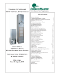
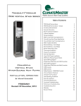
Tranquility® Vertical
Stack (TSM) Series
Submittal Data
Models TSM09 - 36
60Hz - HFC-410A
English Language/I-P Units
SUBMITTAL DATA - I-P UNITS
Unit Designation:
Job Name:
Architect:
Engineer:
Contractor:
PERFORMANCE DATA
Cooling Capacity:
Btuh
EER:
Heating Capacity:
Btuh
COP:
Ambient Air Temp:
°F
Entering Water Temp (Clg):
°F
Entering Air Temp (Clg):
°F
Entering Water Temp (Htg):
°F
Entering Air Temp (Htg):
°F
Airflow:
CFM
Fan Speed or Motor/RPM/Turns:
Revised: 16 December, 2014
Operating Weight:
(lb)
ELECTRICAL DATA
Power Supply:
Volts
Phase
Minimum Circuit Ampacity:
ClimateMaster works continually to improve its products. As a result, the design and specifications of each
product at the time of order may be changed without notice and may not be as described herein. Please contact
ClimateMaster's Customer Service Department at 1-405-745-6000 for specific information on the current design and
specifications. Statements and other information contained herein are not express warranties and do not form the
basis of any bargain between the parties, but are merely ClimateMaster's opinion or commendation of its products.
The latest version of this document is available at climatemaster.com.
*LC994*
LC994
Revised: 16 December, 2014
Maximum Overcurrent Protection:
Hz
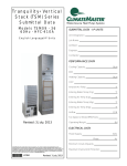
Tranquility® Vertical
Stack (TSM) Series
Submittal Data
Models TSM09 - 36
60Hz - HFC-410A
English Language/S-I Units
SUBMITTAL DATA - S-I UNITS
Unit Designation:
Job Name:
Architect:
Engineer:
Contractor:
PERFORMANCE DATA
Cooling Capacity:
kW
EER:
Heating Capacity:
kW
COP:
Ambient Air Temp:
°C
Entering Water Temp (Clg):
°C
Entering Air Temp (Clg):
°C
Entering Water Temp (Htg):
°C
Entering Air Temp (Htg):
°C
Airflow:
l/s
Fan Speed or Motor/RPM/Turns:
Revised: 16 December, 2014
Operating Weight:
(kg)
ELECTRICAL DATA
Power Supply:
Volts
Phase
Minimum Circuit Ampacity:
ClimateMaster works continually to improve its products. As a result, the design and specifications of each
product at the time of order may be changed without notice and may not be as described herein. Please contact
ClimateMaster's Customer Service Department at 1-405-745-6000 for specific information on the current design and
specifications. Statements and other information contained herein are not express warranties and do not form the
basis of any bargain between the parties, but are merely ClimateMaster's opinion or commendation of its products.
The latest version of this document is available at climatemaster.com.
*LC994*
LC994
Revised: 16 December, 2014
Maximum Overcurrent Protection:
Hz
TSM Series 60Hz - HFC-410A Submittal Data
Eng/I-P
Table of Contents
*Page Number
Unit Features . . . . . . . . . . . . . . . . . . . . . . . . . . . . . . . . . . . . . . . . . . . . . . . . . . . . . . . . . . 4
iGate™ Communicating Controls . . . . . . . . . . . . . . . . . . . . . . . . . . . . . . . . . . . . . . . . . . . . . . 6
vFlow™ Internal Variable Water Flow Control . . . . . . . . . . . . . . . . . . . . . . . . . . . . . . . . . . . 7
Selection Procedure . . . . . . . . . . . . . . . . . . . . . . . . . . . . . . . . . . . . . . . . . . . . . . . . . . . . . 8
TSM Series Nomenclature . . . . . . . . . . . . . . . . . . . . . . . . . . . . . . . . . . . . . . . . . . . . . . . . . 10
TSM Series Nomenclature . . . . . . . . . . . . . . . . . . . . . . . . . . . . . . . . . . . . . . . . . . . . . . . . . 11
Performance Data – AHRI/ASHRAE/ISO 13256-1 . . . . . . . . . . . . . . . . . . . . . . . . . . . . . . . . 13
Performance Data – Selection Notes . . . . . . . . . . . . . . . . . . . . . . . . . . . . . . . . . . . . . . . . . 14
Performance Data – TSM09 with PSC Motor . . . . . . . . . . . . . . . . . . . . . . . . . . . . . . . . . . . 15
Performance Data – TSM12 with PSC Motor . . . . . . . . . . . . . . . . . . . . . . . . . . . . . . . . . . . 16
Performance Data – TSM15 with PSC Motor . . . . . . . . . . . . . . . . . . . . . . . . . . . . . . . . . . . 17
Performance Data – TSM18 with PSC Motor . . . . . . . . . . . . . . . . . . . . . . . . . . . . . . . . . . . 18
Performance Data – TSM24 with PSC Motor . . . . . . . . . . . . . . . . . . . . . . . . . . . . . . . . . . . 19
Performance Data – TSM30 with PSC Motor . . . . . . . . . . . . . . . . . . . . . . . . . . . . . . . . . . . 20
Performance Data – TSM36 with PSC Motor . . . . . . . . . . . . . . . . . . . . . . . . . . . . . . . . . . . 21
Performance Data – TSM09 with ECM Motor . . . . . . . . . . . . . . . . . . . . . . . . . . . . . . . . . . . 22
Performance Data – TSM12 with ECM Motor . . . . . . . . . . . . . . . . . . . . . . . . . . . . . . . . . . . 23
Performance Data – TSM15 with ECM Motor . . . . . . . . . . . . . . . . . . . . . . . . . . . . . . . . . . . 24
Performance Data – TSM18 with ECM Motor . . . . . . . . . . . . . . . . . . . . . . . . . . . . . . . . . . . 25
Performance Data – TSM24 with ECM Motor . . . . . . . . . . . . . . . . . . . . . . . . . . . . . . . . . . . 26
Performance Data – TSM30 with ECM Motor . . . . . . . . . . . . . . . . . . . . . . . . . . . . . . . . . . . 27
Performance Data – TSM36 with ECM Motor . . . . . . . . . . . . . . . . . . . . . . . . . . . . . . . . . . . 28
Performance Data – TSM09 with Modulating Valve or Variable Speed Pump . . . . . . . . . . . . . . 29
Performance Data – TSM12 with Modulating Valve or Variable Speed Pump . . . . . . . . . . . . . . 30
Performance Data – TSM15 with Modulating Valve or Variable Speed Pump . . . . . . . . . . . . . . 31
Performance Data – TSM18 with Modulating Valve or Variable Speed Pump . . . . . . . . . . . . . . 32
Performance Data – TSM24 with Modulating Valve or Variable Speed Pump . . . . . . . . . . . . . . 33
Performance Data – TSM30 with Modulating Valve or Variable Speed Pump . . . . . . . . . . . . . . 34
Performance Data – TSM36 with Modulating Valve or Variable Speed Pump . . . . . . . . . . . . . . 35
Performance Data Correction Tables . . . . . . . . . . . . . . . . . . . . . . . . . . . . . . . . . . . . . . . . 36
vFlow - Modulating Valve and Variable Pump Tables. . . . . . . . . . . . . . . . . . . . . . . . . . . . . . 37
PSC Blower Performance Data . . . . . . . . . . . . . . . . . . . . . . . . . . . . . . . . . . . . . . . . . . . . . 38
ECM Blower Performance Data . . . . . . . . . . . . . . . . . . . . . . . . . . . . . . . . . . . . . . . . . . . . . 39
Sound Data . . . . . . . . . . . . . . . . . . . . . . . . . . . . . . . . . . . . . . . . . . . . . . . . . . . . . . . . . . . 40
Physical Data . . . . . . . . . . . . . . . . . . . . . . . . . . . . . . . . . . . . . . . . . . . . . . . . . . . . . . . . . 41
Electrical Data - PSC Motor . . . . . . . . . . . . . . . . . . . . . . . . . . . . . . . . . . . . . . . . . . . . . . 42
TSM Series Wiring Diagram Matrix . . . . . . . . . . . . . . . . . . . . . . . . . . . . . . . . . . . . . . . . . . . 44
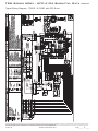
Typical Wiring Diagram – TSM09 - 36 CXM with PSC Motor . . . . . . . . . . . . . . . . . . . . . . . . . 45
Typical Wiring Diagram – TSM09 - 36 DXM2 with PSC Motor . . . . . . . . . . . . . . . . . . . . . . . . 46
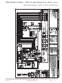
Typical Wiring Diagram – TSM09 - 12 DXM2 with ECM Motor . . . . . . . . . . . . . . . . . . . . . . . . 47
Typical Wiring Diagram – TSM15 - 36 DXM2 with ECM Motor . . . . . . . . . . . . . . . . . . . . . . . . 48
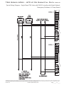
Typical Wiring Diagram – Single Phase TSM Units with DXM2 Controller with Night Setback,
Emergency Shutdown, & Pump Restart. . . . . . . . . . . . . . . . . . . . . . . . . . . . . . . . . . . . . . . . 49
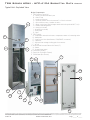
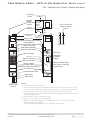
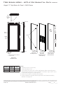
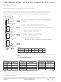
Typical Unit - Exploded View . . . . . . . . . . . . . . . . . . . . . . . . . . . . . . . . . . . . . . . . . . . . . . . 50
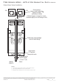
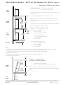
TSM – Standard Unit, Furred In Cabinet with Risers. . . . . . . . . . . . . . . . . . . . . . . . . . . . . . 51
TSM – Master Unit, Furred In Cabinet . . . . . . . . . . . . . . . . . . . . . . . . . . . . . . . . . . . . . . . . 52
TSM – Slave Unit, Furred In Cabinet, No Risers . . . . . . . . . . . . . . . . . . . . . . . . . . . . . . . . . 53
Master/Slave Cabinet Installation . . . . . . . . . . . . . . . . . . . . . . . . . . . . . . . . . . . . . . . . . . 54
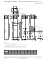
Cabinet Dimensions. . . . . . . . . . . . . . . . . . . . . . . . . . . . . . . . . . . . . . . . . . . . . . . . . . . . . . 55
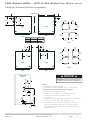
Cabinet Slot Dimensions and Riser Arrangements . . . . . . . . . . . . . . . . . . . . . . . . . . . . . . . 56
TSM Cabinet Configurations . . . . . . . . . . . . . . . . . . . . . . . . . . . . . . . . . . . . . . . . . . . . . . . 57
Typical Cabinet Installation - Flush . . . . . . . . . . . . . . . . . . . . . . . . . . . . . . . . . . . . . . . . . 58
Typical Cabinet Installation - Recessed . . . . . . . . . . . . . . . . . . . . . . . . . . . . . . . . . . . . . . . 59
Hinged “G” Style Return Air Panel – AVHSG Series . . . . . . . . . . . . . . . . . . . . . . . . . . . . . . 60
AHH Series – Stainless Steel Braided Hose Kit . . . . . . . . . . . . . . . . . . . . . . . . . . . . . . . . . 61
ACST Cabinet Stands . . . . . . . . . . . . . . . . . . . . . . . . . . . . . . . . . . . . . . . . . . . . . . . . . . . . 61
Supply Air Openings and Grilles . . . . . . . . . . . . . . . . . . . . . . . . . . . . . . . . . . . . . . . . . . . . 62
Thermostats . . . . . . . . . . . . . . . . . . . . . . . . . . . . . . . . . . . . . . . . . . . . . . . . . . . . . . . . . . 63
TSM Options . . . . . . . . . . . . . . . . . . . . . . . . . . . . . . . . . . . . . . . . . . . . . . . . . . . . . . . . . . 64
ECM Blower Motor (Optional) . . . . . . . . . . . . . . . . . . . . . . . . . . . . . . . . . . . . . . . . . . . . . . 65
Riser Definitions . . . . . . . . . . . . . . . . . . . . . . . . . . . . . . . . . . . . . . . . . . . . . . . . . . . . . . . 66
Riser GPM Definitions and Sizing . . . . . . . . . . . . . . . . . . . . . . . . . . . . . . . . . . . . . . . . . . . 67
Riser Diameter Sizing . . . . . . . . . . . . . . . . . . . . . . . . . . . . . . . . . . . . . . . . . . . . . . . . . . . . 68
Riser Length Definitions and Sizing . . . . . . . . . . . . . . . . . . . . . . . . . . . . . . . . . . . . . . . . . 69
Riser Extension Definitions and Sizing . . . . . . . . . . . . . . . . . . . . . . . . . . . . . . . . . . . . . . . 70
Setting Cabinet . . . . . . . . . . . . . . . . . . . . . . . . . . . . . . . . . . . . . . . . . . . . . . . . . . . . . . . . 71
Slab Slot Chart - 3 Pipe. . . . . . . . . . . . . . . . . . . . . . . . . . . . . . . . . . . . . . . . . . . . . . . . . . 72
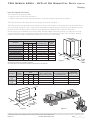
Shipping . . . . . . . . . . . . . . . . . . . . . . . . . . . . . . . . . . . . . . . . . . . . . . . . . . . . . . . . . . . . . 73
Engineering Specifications . . . . . . . . . . . . . . . . . . . . . . . . . . . . . . . . . . . . . . . . . . . . . . . . 74
Revision History . . . . . . . . . . . . . . . . . . . . . . . . . . . . . . . . . . . . . . . . . . . . . . . . . . . . . . . 84
*Document page number is shown next to part number (e.g. LC994 - 3 = page 3). Since not all pages are typically
used in the submittals process, the page number in the lower right corner can still be used (page ____of_____).
ClimateMaster works continually to improve its products. As a result, the design and specifications of each product at the time of order may be changed without notice and may not be as described herein. Please contact ClimateMaster's Customer
Service Department at 1-405-745-6000 for specific information on the current design and specifications. Statements and other information contained herein are not express warranties and do not form the basis of any bargain between the parties,
but are merely ClimateMaster's opinion or commendation of its products. The latest version of this document is available at climatemaster.com.
LC994 - 3
Revised: 16 December, 2014
Page ______ of ______
TSM Series 60Hz - HFC-410A Submittal Data
Eng/I-P
Unit Features
TRANQUILITY® VERTICAL STACK (TSM) SERIES WITH
EARTHPURE® REFRIGERANT
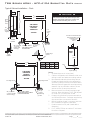
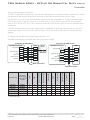
The Tranquility® Vertical Stack (TSM) Series offers an innovative, labor-saving solution for spaces where individual,
quiet control of the heating and cooling system is important. TSM units’ consist of 2 major components - cabinet
behind finished wall and slide in refrigeration chassis.
Vertical risers running behind cabinet are especially ideal
for multi-story buildings. Risers can be ordered assembled
to cabinet or shipped separate so riser stack can be completely assembled, pressure tested, filled, and water circulated. This allows floor by floor completion and occupancy
before construction is completed. TSM units can operate
as stand-alone “ductless” systems, or can be ducted to
an adjacent room, making them convenient for low-rise
buildings as well. The TSM Series exceeds ASHRAE 90.1
efficiencies, yet maintains small cabinet dimensions. Using
EarthPure® (HFC-410A) refrigerant, the TSM Series not
only protects the environment, it does so while delivering
unprecedented comfort, efficiency, and reliability.
Available in sizes 3/4 ton (2.6 kW) through 3 tons (10.6 kW)
with numerous cabinet, water piping and control choices,
the TSM Series offers a wide range of units for most any
installation. The TSM has an extended range refrigerant
circuit, capable of ground loop (geothermal) applications
as well as water loop (boiler-tower) applications. Standard
features are many. Microprocessor controls, TXV metering
device, galvanized steel cabinet, torsion-flex blower
motor mounting, and (optional) ECM motor for all models
are just some of the features of the innovative TSM Series.
ClimateMaster’s exclusive double isolation compressor
mounting system makes the TSM Series the quietest
vertical stack units on the market. Compressors are
mounted on specially engineered sound-tested EPDM
grommets to a heavy gauge base pan, which is then
isolated from the cabinet base with grommets under
the condensate pan for maximized vibration/sound
attenuation. Factory-installed internal options such
as DDC controls, ECM motors, single speed pump,
variable speed pump, auto flow water regulator, 2-way
water solenoid valve, and modulating water valve allow
customized design solutions.
iGate™ technology is the next generation in intelligent
control by using two-way communication to provide
a gateway into the system. The iGate™ control system
allows end-users and contractors to monitor the performance of the unit, custom tailor its operation, and
diagnose any issues, right from the ATC thermostat, or
diagnostic tool.
The iGate™ communications hub is the DXM2 intelligent
controller, which analyzes the status of sensors and smart
components (which are also two-way communicating)
to determine how best to operate the system for optimal comfort, efficiency and long-term reliability. All of
this information is passed to the iGate™ thermostat (or
diagnostic tool), where it can be displayed in plain English. And since communication is both ways, the iGate™
thermostat can also be used to configure and tailor the
system without even touching the unit.
vFlow™ variable water flow technology represents a major
advance in water-source system performance made possible through the iGate™ system. vFlow™ not only builds
the major water circulation components into the unit for
a clean installation, it also intelligently varies the water
flow to minimize pump energy consumption and improve
system reliability. vFlow™ also allows cooling and heating
operation across the entire 20–120°F entering water conditions, providing ultimate flexibility in designing watersource heating and cooling systems with ClimateMaster
vFlow™ units.
The heart of vFlow™ is either a variable-speed pump or
modulating water valve directly linked into the iGate™
system. Water flow is automatically varied based on T,
in turn changes in unit capacity level (stage) and source
water temperature to maintain optimum system performance. vFlow™ allows the use of direct return piping,
while eliminating external two-ways valves and automatic
flow regulators. vFlow™ systems are inherently selfbalancing. vFlow™ with automatically modulating valves
deliver superior value by being priced competitively with
inefficient two-way valve with auto flow regulator options.
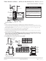
ATTENTION!
TSM has different riser configurations than TRM.
TSM chassis will not fit into the TRM Cabinet.
TSM return air side is defined as the front of unit.
TSM - G panel only.
TSM - All Cabinets - Field must remove supply air knockouts, install duct angles, and remove riser knockouts.
ClimateMaster works continually to improve its products. As a result, the design and specifications of each product at the time of order may be changed without notice and may not be as described herein. Please contact ClimateMaster's Customer
Service Department at 1-405-745-6000 for specific information on the current design and specifications. Statements and other information contained herein are not express warranties and do not form the basis of any bargain between the parties,
but are merely ClimateMaster's opinion or commendation of its products. The latest version of this document is available at climatemaster.com.
LC994 - 4
Revised: 16 December, 2014
Page ______ of ______
TSM Series 60Hz - HFC-410A Submittal Data
Eng/I-P
Unit Features
vFlow™ systems provide reduced water pumping power
compared to traditional fixed-speed pumping or
fixed water flow systems and protects the unit against
extreme operating conditions, extending the life of the
compressor and air coil. Since vFlow™ is built inside the
unit, it also saves on installation time and makes for a
very clean and compact installation. The Tranquility® TSM
Series water-source heat pumps are designed to meet
the challenges of today’s HVAC demands with one of the
most innovative products available on the market.
The TSM Series Vertical Stack Water-Source Heat Pumps
are designed to meet the challenges of today’s HVAC
demands with a low cost/high value solution.
UNIT FEATURES
• Sizes 09 (3/4 ton, 2.6 kW) through 36 (3 ton, 10.6 kW)
• Environmentally-friendly EarthPure® (HFC-410A) zero
ozone depletion refrigerant
• High efficiency rotary and scroll compressors
• Exceeds ASHRAE 90.1 efficiencies
• Removable chassis allows staged installation and ease
of maintenance
• Galvanized steel cabinet
• Chassis rests on rubber grommeted isolated
condensate pan for vibration reduction.
• Double isolation of compressor for quiet operation
• UltraQuiet option
• Air coil hairpins are tin-plated; Option non-plated
• TXV metering device
• Cabinet construction for unit or remote-mounted
controls
• Two fan speed capability with CXM or DXM2
• Microprocessor controls standard (optional DXM2 and/
or DDC controls)
• Optional Advanced Controls - iGate™ communicating
control provides advanced unit functionality and
comprehensive configuration, monitoring and
diagnostic capabilities through digital communication
links with the variable-speed fan motor, variable-speed
source pump (or modulating valve) and communicating
thermostat or Configuration/Diagnostic tool.
• 7 temperature sensor inputs for system protection
and control
• Anti-short cycle and over/under voltage protection
• High pressure, loss of charge, and condensate
overflow protection
• LED fault and status indication at controller
• Service tool port for optional setup and
diagnostics at unit
• Eight Safeties Standard.
• Filter Rail for 1" or 2" Filter
• LonWorks, BACnet, Modbus and Johnson N2
compatibility options for DDC controls
• Unit Performance Sentinel performance monitoring
system
• Integrated drain pan with condensate overflow sensor
• Attractive return air panel with hinged access door
(“G” panel) - option key locked.
• Multiple supply air discharge options
• Full port shut-off valves with memory stop, for supply
and return, located opposite return air panel inside
cabinet
• Stainless steel braided hose kits for connection from
piping risers to chassis
• Wide variety of cabinet options including disconnect
switch, breaker, thermostat whip with molex connector,
isolation pad, stainless steel drain pan, riser chase, and
ECM variable speed communicating and electric heat
motor.
• Wide variety of chassis options including stainless
steel drain pan, insulated tubing for extended
range operation, vFlow™ (modulating valve normally
closed or variable speed pump), autoflow regulator,
motorized water valve (normally closed), secondary
circulating pump, and cupro-nickel coaxial heat
exchanger
• Selection of thermostats including manual changeover,
automatic changeover, or programmable are available.
• Accessory Filters, 1" Merv 8 and 11; 2" Merv 8 and 13
ClimateMaster works continually to improve its products. As a result, the design and specifications of each product at the time of order may be changed without notice and may not be as described herein. Please contact ClimateMaster's Customer
Service Department at 1-405-745-6000 for specific information on the current design and specifications. Statements and other information contained herein are not express warranties and do not form the basis of any bargain between the parties,
but are merely ClimateMaster's opinion or commendation of its products. The latest version of this document is available at climatemaster.com.
LC994 - 5
Revised: 16 December, 2014
Page ______ of ______
TSM Series 60Hz - HFC-410A Submittal Data
Eng/I-P
iGate™ Communicating Controls
ECM
Blower
Motor
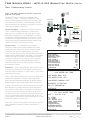
iGate™ Information gateway to monitor, control and
diagnose your system
Tranquility® Vertical Stack Series is equipped with
industry-first, iGate™ – Information Gateway – 2-way
communicating system that allows users to interact with
their water-source system in plain English AND delivers
improved reliability and efficiency by precisely controlling
smart variable speed components.
Communicating
Thermostat
DXM2
Or
Sensors
Monitor/Configure – Installers can configure from the
iGate™ communicating thermostat or configuration/
diagnostic tool, including: Air flow, loop delta T, waterflow option configuration, unit configuration, accessory
configuration, and demand reduction (optional, to limit
unit operation during peak times). Users can look up the
current system status: temperature sensor readings and
operational status of the blower and pump.
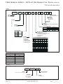
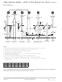
Precise Control – The new DXM2 board enables
intelligent, 2-way communication between the DXM2
board and smart components like the communicating
thermostat, fan motor, and water pump. The DXM2
control can also directly control the modulating valve and
accepts various feedback/input (see figure). The Intelligent
DXM2 board uses information received from the smart
components and sensors to precisely control operation
of variable speed fan, variable speed water pump (or
modulating valve) to deliver higher efficiency, reliability
and increased comfort.
Diagnostics – iGate™ takes diagnosing geothermal units
to a next level of simplicity, by providing a dashboard of
system and fault information, in plain English, on the iGate
thermostat/ service tool.
iGate™ Service Warning warns the occupant of a fault and
displays fault description, possible causes and current
system status (temperature readings, fan RPM and water
flow status) which may be reported to service personnel.
In iGate™ Service Mode, the service personnel can access
fault description, possible causes and most importantly,
the conditions (temp, flow, i/o conditions, configuration)
at the time of the fault. Manual Operation mode allows
the service personnel to manually command operation for
any of the thermostat outputs, blower speed, as well as
pump speed or valve position from the thermostat, to help
troubleshoot specific components.
With iGate™ communicating system, users and contractors
have a gateway to system information never before
available.
Diagnostic
Tool
Two-Way Communication
One-Way Communication
Or
Mot.
Modulating
Valve
Variable
Speed
Pump
AIRFLOW SELECTION
HEAT STAGE 1
HEAT STAGE 2
AUXILIARY HEAT
EMERGENCY HEAT
COOL STAGE 1
COOL STAGE 2
COOL DEHUMID 1
COOL DEHUMID 2
CONTINUOUS FAN
HEAT OFF DELAY
COOL OFF DELAY
PREVIOUS
CFM
600
750
850
850
525
700
425
550
350
60
30
NEXT
POSSIBLE FAULT CAUSES
LOW WATER COIL TEMP
LOW WATER TEMP - HTG
LOW WATER FLOW - HTG
LOW REFRIG CHARGE - HTG
INCORRECT LT1 SETTING
BAD LT1 THERMISTOR
PREVIOUS
FAULT TEMPERATURE CONDITIONS
LT1 LOW WATER TEMP
HEAT 1 11:11 AM 11/14
LT1 TEMP
LT2 TEMP
HOT WATER EWT
COMP DISCHARGE
LEAVING AIR
LEAVING WATER
ENTERING WATER
CONTROL VOLTAGE
28.1
97.3
121.5
157.7
92.7
34.9
42.1
26.4
PREVIOUS
ClimateMaster works continually to improve its products. As a result, the design and specifications of each product at the time of order may be changed without notice and may not be as described herein. Please contact ClimateMaster's Customer
Service Department at 1-405-745-6000 for specific information on the current design and specifications. Statements and other information contained herein are not express warranties and do not form the basis of any bargain between the parties,
but are merely ClimateMaster's opinion or commendation of its products. The latest version of this document is available at climatemaster.com.
LC994 - 6
Revised: 16 December, 2014
Page ______ of ______
TSM Series 60Hz - HFC-410A Submittal Data
Eng/I-P
vFlow™ Internal Variable Water Flow Control
vFlow™ Internal Variable Water Flow
Industry-first, Built-in vFlow™ provide an ultra-highefficient, variable speed, internal water flow system. It
saves installers time and labor by avoiding installing
bulky external pumps, valves, or flow regulators. Multiunit installations are also much simpler with vFlow™
systems, as the units automatically adjust water flow
across the system.
vFlow™ is enabled by iGate™, which facilitates intelligent
communication between the thermostat, DXM2 control,
sensors and internal water pump/valve to make true
variable water flow a reality.
™
vFlow is available in two variations:
1. Low System Pressure Drop Modulating Valve – High
CV motorized valve for central pumping.
2. Standard Head Variable Pump – multi unit/central
pumping.
vFlow™ delivers three main benefits:
1. Easier and quicker unit installation as the flow control
is built in to the unit.
2. Superior reliability by varying the water flow to deliver
more stable operation across the entering water
range (20°–120°F, heating and cooling).
3. Higher cost savings by varying the flow (and pump
watt consumption) to match the unit’s mode of
operation.
Variable flow
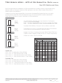
vFlow™ technology enables variable water flow through
the unit, with the DXM2 control adjusting the pump
speed to maintain an installer-set loop delta T. By
controlling the water flow, the system is able to operate
at its optimal capacity and efficiency. vFlow™ provides a
lower flow rate for part load where units typically operate
80% of the time and a higher, more normal flow rate for
full load operation.
Variable speed pump or motorized modulating
valve delivers variable water-flow, controlled
by DXM2 control, based on loop water ∆T.
Energy Savings with water circulation control
Units with vFlow™ deliver higher operating cost savings
by varying the water flow to match the unit’s operation
(ex: lower water flow when unit is in part load operation).
Lowering the flow results in lower energy consumption by
the water pump (=higher cost savings) in vFlow™ units.
In applications using vFlow™ with internal variable-speed
(ECM) pump, the ECM pump uses fewer watts than a
fixed speed (PSC) pump, even at full load. The ECM
pump excels in energy savings in part load, saving 70
–80% watts compared to fixed speed pumps (see chart).
The ECM pump can operate with independent flow rates
for heating and cooling, further saving more energy.
In applications using vFlow™ with modulating valve,
when the motorized modulating valve slows down the
water flow during part load operation, the external pump
consumes fewer watts, thus saving more energy.
ClimateMaster works continually to improve its products. As a result, the design and specifications of each product at the time of order may be changed without notice and may not be as described herein. Please contact ClimateMaster's Customer
Service Department at 1-405-745-6000 for specific information on the current design and specifications. Statements and other information contained herein are not express warranties and do not form the basis of any bargain between the parties,
but are merely ClimateMaster's opinion or commendation of its products. The latest version of this document is available at climatemaster.com.
LC994 - 7
Revised: 16 December, 2014
Page ______ of ______
TSM Series 60Hz - HFC-410A Submittal Data
Eng/I-P
Selection Procedure
Reference Calculations
Heating
Cooling
HE
LWT = EWT GPM x Constant
LAT = EAT +
HC
CFM x1.08
LWT = EWT +
HE
GPM x Constant
LAT (DB) = EAT (DB) -
LC = TC - SC
SC
CFM x1.08
S/T =
SC
TC
Constant = 500 for water, 485 for antifreeze.
Legend and Glossary of Abbreviations
BTUH = BTU( British Thermal Unit) per hour
CFM = airflow, cubic feet/minute
COP = coefficient of performance = BTUH output/BTUH input
DB = dry bulb temperature (°F)
EAT = entering air temperature, Fahrenheit (dry bulb/wet bulb)
EER = energy efficiency ratio = BTUH output/Watt input
MPT = male pipe thread
ESP = external static pressure (inches w.g.)
EWT = entering water temperature
GPM = water flow in U.S. gallons/minute
HE = total heat of extraction, BTUH
HC = air heating capacity, BTUH
HR = total heat of rejection, BTUH
HWC
FPT
KW
LAT
LC
LWT
MBTUH
S/T
SC
TC
WB
WPD
= hot water generator (desuperheater) capacity, Mbtuh
= female pipe thread
= total power unit input, kilowatts
= leaving air temperature, °F
= latent cooling capacity, BTUH
= leaving water temperature, °F
= 1000 BTU per hour
= sensible to total cooling ratio
= sensible cooling capacity, BTUH
= total cooling capacity, BTUH
= wet bulb temperature (°F)
= waterside pressure drop (psi & ft. of hd.)
Conversion Table - to convert inch-pound (English) to S-I (Metric)
Air Flow
Water Flow
Ext Static Pressure
Water Pressure Drop
Airflow (L/s) = CFM x 0.472
Water Flow (L/s) = gpm x 0.0631
ESP (Pa) = ESP (in of wg) x 249
PD (kPa) = PD (ft of hd) x 2.99
ClimateMaster works continually to improve its products. As a result, the design and specifications of each product at the time of order may be changed without notice and may not be as described herein. Please contact ClimateMaster's Customer
Service Department at 1-405-745-6000 for specific information on the current design and specifications. Statements and other information contained herein are not express warranties and do not form the basis of any bargain between the parties,
but are merely ClimateMaster's opinion or commendation of its products. The latest version of this document is available at climatemaster.com.
LC994 - 8
Revised: 16 December, 2014
Page ______ of ______
TSM Series 60Hz - HFC-410A Submittal Data
Eng/I-P
Selection Procedure
Step 1 Determine the actual heating and cooling loads at the
desired dry bulb and wet bulb conditions.
Step 2 Obtain the following design parameters: Entering water
temperature, water flow rate in GPM, air flow in CFM,
water flow pressure drop and design wet and dry bulb
temperatures. Air flow CFM should be between 300 and
500 CFM per ton. Unit water pressure drop should be
kept as close as possible to each other to make water
balancing easier. Go to the appropriate tables and find
the proper indicated water flow and water temperature.
Step 3 Select a unit based on total and sensible cooling
conditions. Select a unit which is closest to, but no
larger than, the actual cooling load.
Step 4 Enter tables at the design water flow and water
temperature. Read the total and sensible cooling
capacities (Note: interpolation is permissible,
extrapolation is not).
Step 5 Read the heating capacity. If it exceeds the design
criteria it is acceptable. It is quite normal for WaterSource Heat Pumps to be selected on cooling capacity
only since the heating output is usually greater than the
cooling capacity.
Step 6 Determine the correction factors associated with the
variable factors of dry bulb, wet bulb, and air flow.
Corrected Total Cooling = tabulated total cooling x wet
bulb correction x air flow correction.
Example Equipment Selection For Cooling
Step 1 Load Determination:
Assume we have determined that the appropriate cooling load
at the desired dry bulb 80°F and wet bulb 65°F conditions is
as follows
Total Cooling ............................................................ 17,000 BTUH
Sensible Cooling...................................................... 12,000 BTUH
Entering Air Temp.......................80°F Dry Bulb / 65°F Wet Bulb
Step 2 Design Conditions:
Similarly, we have also obtained the following design parameters:
Entering Water Temp ............................................................. 90°F
Water Flow (Based upon 10°F rise in temp.) ................. 5.1 GPM
Air Flow at ESP Unit ................................ 630 CFM (90% of rated)
Step 3, 4 & 5 HP Selection:
After making our preliminary selection (TSM18 with PSC motor),
we enter the tables at design water flow and water temperature
and read Total Cooling, Sens. Cooling and Heat of Rej.
capacities:
Total Cooling ...........................................................18,350 BTUH
Sensible Cooling...................................................... 13,210 BTUH
Heat of Rejection ..................................................... 22,470 BTUH
Step 6 & 7 Entering Air and Airflow Corrections:
Corrected Sensible Cooling = tabulated sensible cooling
x wet/dry bulb correction, and air flow correction.
Step 7 Compare the corrected capacities to the load
requirements. Normally if the capacities are within 10%
of the loads, the equipment is acceptable. It is better
to undersize than oversize, as undersizing improves
humidity control, reduces sound levels and extends the
life of the equipment.
Step 8 When completed, calculate water temperature rise
and assess the selection. If the units selected are not
within 10% of the load calculations, then review what
effect changing the GPM, water temperature and/or air
flow and air temperature would have on the corrected
capacities. If the desired capacity cannot be achieved,
select the next larger or smaller unit and repeat the
procedure. Remember, when in doubt, undersize
slightly for best performance.
Next, we determine our correction factors.
Table
Ent Air
Corrected Total Cooling = 18,350
Corrected Sens Cooling = 13,210
Corrected Heat of Reject = 22,470
Air Flow
Corrected
x 0.975 x 0.971 = 17,372
x 0.999 x 0.932 = 12,299
x 0.982 x 0.979 = 21,602
Step 8 Water Temperature Rise Calculation & Assessment:
Actual Temperature Rise ...................................................... 8.8°F
When we compare the Corrected Total Cooling and Corrected
Sensible Cooling figures with our load requirements stated
in Step 1, we discover that our selection is within +/- 10%
of our sensible load requirement. Furthermore, we see that
our Corrected Total Cooling figure is slightly undersized as
recommended, when compared to the actual indicated load.
ClimateMaster works continually to improve its products. As a result, the design and specifications of each product at the time of order may be changed without notice and may not be as described herein. Please contact ClimateMaster's Customer
Service Department at 1-405-745-6000 for specific information on the current design and specifications. Statements and other information contained herein are not express warranties and do not form the basis of any bargain between the parties,
but are merely ClimateMaster's opinion or commendation of its products. The latest version of this document is available at climatemaster.com.
LC994 - 9
Revised: 16 December, 2014
Page ______ of ______
TSM Series 60Hz - HFC-410A Submittal Data
Eng/I-P
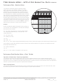
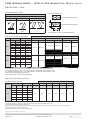
TSM Series Nomenclature
Cabinet
1
2
3
C1 G
4
5
0
N
11
12
13
14
15
0 A 1 0 0 0
0
0
0
A
6
7
8
9
10
REVISION LEVEL
CABINET SIZE
A = CURRENT REVISION
1 = 09
2 = 12
3 = 15
4 = 18
5 = 24
6 = 30
7 = 36
STANDARD
0 = STANDARD
A, B, C etc.... = SPECIAL 1, 2, 3 etc....
T-STAT WHIP
0 = No Whip
1 = 15’ whip
2 = 25’ whip
3 = 35’ whip
VOLTAGE
OPTION
Volt/Hertz/Phaze
G
E
208-230/60/1
265/60/1
SIDE Discharge Air
0 = No Opening
1 = Right Opening
2 = Left Opening
3 = Right & Left Opening
OPTIONS
–
X
X
–
–
X
X
–
BACK/FRONT/TOP Discharge Air
1Ý
1Ý
1Ý
1Ý
2Ý
2Ý
2Ý
2Ý
X
–
X
–
X
–
X
–
0 = No Opening
1 = Back Opening
2 = Front Opening
3 = Top Opening
4 = Back & Top Opening
5 = Front & Top Opening
6 = Back & Front Opening
7 = Back, Front & Top Opening
HARNESS CONTROLS
STD
OPTION PSC ECM
A
B
C
D
L
M
N
P
R
S
X
–
X
–
X
–
X
X
–
–
DISCHARGE OPENINGS BY UNIT SIZE 80”
UNIT SIZE
09 thru 18
24 thru 36
–
X
–
X
–
X
–
–
X
X
0 = None
2 = Chase
–
–
M
M
L
L
–
–
–
–
A
A
W
W
W
W
R
S
R
S
DIGIT 9 - 2 S R
U
P
LEFT P
L
Y
0 = SLAVE / NONE
1 = STANDARD
2 = MASTER
DISCONNECT SWITCH BREAKER ISP / BREAKER ELECTRIC HEATER
X
BACK
DIGIT 9 - 3
NO OPTIONS
S
U
P
P RIGHT
L
Y
FRONT
DIGIT 9 - 4
BACK
SUPPLY
RETURN
DRAIN
LEFT
RIGHT
FRONT
{RETURN AIR}
CABINET HEIGHT
X
0
R
E
T
U
R
N
D
R
A
I
N
{RETURN AIR}
X
X
X
X
X
D
R
A
I
N
FRONT
RISER: LOCATION
0 = None
1 = Shipped Separately (Risers, Cabinet, Chassis)
2 = Left Back
3 = Right Back
4 = Left Side
5 = Right Side
6 = Chassis ships in Cabinet (Riser Separate)
E
T
U
R
N
{RETURN AIR}
RISER STYLE
A
B
C
2
3
4
5
Front
12” x 6”
16” x 6”
Top
12” x 12”
16” x 16”
BACK
RISER CHASE
S=SURFACE
M = MPC
R =REMOTE
W = WALL SENSOR L = LON
A = ADA
POWER TERMINATION
OPTION
Back, Front & Side
12” x 6” & 12” x 12”
16” x 8” & 16” x 16”
Top
12” x 12”
16” x 16”
1Ý and 2Ý FILTER
OPTION S.S. DRAIN PAN PREMIUM SEAL
A
B
C
0
1
2
3
4
DISCHARGE OPENINGS BY UNIT SIZE 88”
UNIT SIZE
09 thru 18
24 thru 36
2.5 KW, 208/230V
5.0 KW, 208/230V
2.5 KW, 265V
5.0 KW, 265V
OPTION
A
B
C
D
80”
88”
DIGIT 9 - 5
X
X
X
BACK
ISO PAD
X
X
X
SUPPLY
RETURN
DRAIN
LEFT
RIGHT
FRONT
{RETURN AIR}
ATTENTION!
TSM has different riser configurations than TRM.
TSM chassis will not fit into the TRM Cabinet.
TSM return air side is defined as the front of unit.
TSM - G panel only.
TSM - All cabinets - field must remove supply air knockouts and install duct angles.
NOTICE!
Front of cabinet is return air side, risers can be on any other side (left, right, or back).
ClimateMaster works continually to improve its products. As a result, the design and specifications of each product at the time of order may be changed without notice and may not be as described herein. Please contact ClimateMaster's Customer
Service Department at 1-405-745-6000 for specific information on the current design and specifications. Statements and other information contained herein are not express warranties and do not form the basis of any bargain between the parties,
but are merely ClimateMaster's opinion or commendation of its products. The latest version of this document is available at climatemaster.com.
LC994 - 10
Revised: 16 December, 2014
Page ______ of ______
TSM Series 60Hz - HFC-410A Submittal Data
Eng/I-P
TSM Series Nomenclature
Chassis
1 2
3
TSM
4 5
6
7
8
9
10
11
12
13
09
G
S
A
S
S
C
S
S S A
15
14
Revision Level
Series
A = Current Revision Level
TSM = TRANQUILITY®
HIGH RISE CHASSIS
Standard
S = Standard
A = Special #1
B = Special #2
Etc.....
Unit Size
09
12
15
18
24
30
36
Future Use
S = Standard
Shipping
6 = Chassis Will Ship In Cabinet (Risers Not Attached)
S = Standard
Voltage
E = 265/60/1
G = 208-230/60/1
Heat Exchanger Options
Tin Plated Air Coil
Position 11
Chassis Options
A
S.S.
Drain
Pan
X
B
–
X
C
S
X
–
X
–
OPTION
Controls
C1
12
C2
15
C3
18
C4
24
C5
30
C6
36
C7
Cupro-nickel
Standard Tubing
C
N
L
M
Insulated Tubing
(Extended Range)
D
E
F
G
AUTO-FLOW REGULATOR (US GPM) CODE
A = CXM w/PSC
B = DXM2 w/ECM
C = DXM2 w/PSC
1 = CXM w/PSC w/EH
2 = DXM2 w/ECM w/EH
3 = DXM2 w/PSC w/EH
Cabinet
Copper
S = No Water valve
M = Standard Water Valve (Normally Closed)
P = Secondary Circulating Pump
T = Modulating Valve
U = UPM-Geo
–
09
Cupro-nickel
Water Valve & Pump Option
ULTRAQUIET
Chassis
Non-Coated Air Coil
Copper
5/8 SWEAT
UNIT
09
1.5
UNIT
12
2.0
7/8 SWEAT
UNIT
15
-
UNIT
18
-
UNIT
24
C
D 2.0
2.5
2.5
E 2.5
3.0
3.0
3.0
F 3.0
3.5
3.5
3.5
G
4.0
4.0
4.0
H
J
5.0
5.0
6.0
K
L
7.0
M N
P
S = STANDARD - NO FLOW REGULATOR
UNIT
30
-
UNIT
36
-
-
-
-
-
5.0
6.0
6.0
7.0
8.0
-
-
7.0
8.0
9.0
10.0
Hose Kit
1 2 3
4
5
6
7
8
AH H 0 5 0 3 B
Group
Revision Level
B = Current Revision
AHH = Accessory Hose Kit Hi-Rise
Hose Size
050 = 1/2” Nominal
075 = 3/4” Nominal
100 = 1” Nominal
Length
3 = Length in Feet
ClimateMaster works continually to improve its products. As a result, the design and specifications of each product at the time of order may be changed without notice and may not be as described herein. Please contact ClimateMaster's Customer
Service Department at 1-405-745-6000 for specific information on the current design and specifications. Statements and other information contained herein are not express warranties and do not form the basis of any bargain between the parties,
but are merely ClimateMaster's opinion or commendation of its products. The latest version of this document is available at climatemaster.com.
LC994 - 11
Revised: 16 December, 2014
Page ______ of ______
TSM Series 60Hz - HFC-410A Submittal Data
Eng/I-P
TSM Series Nomenclature
Return Air Panel
1
2
3
5
4
7
6
AVHS G 1 S
8
9
10
11
F S M S
STANDARD
ACCESSORY VHS
RETURN AIR PANEL
S = STANDARD
DESCRIPTION
TYPE
“G”
REVISION LEVEL
Removable
Fixed
“A”
M = CURRENT REVISION TSM (”G” PANEL)
A = CURRENT REVISION TSM (”A” PANEL)
UNIT SIZE
OPTION
1
2
3
STYLE
TSM/TSL
09, 12, 15, 18
N/A
24, 30, 36
A = DOOR w/ADA TSTAT MOUNTING
B = DOOR w/ADA TSTAT MOUNTING & GRILLE
C = DOOR w/ADA TSTAT MOUNTING & LOCK
D = DOOR w/ADA TSTAT MOUNTING, GRILLE, & LOCK
G = DOOR w/GRILLE (20 GA. SHEET METAL) 24-36
K = DOOR w/KEY LOCKS & GRILLE (18 GA. SHEET METAL)
L = DOOR w/KEY LOCKS (18 GA. SHEET METAL)
S = STANDARD (20 GA. SHEET METAL)
COLOR
S = STANDARD (POLAR ICE)
INSULATION TYPE
F = FIBERGLASS
“A” - Requires 48A0700N01 Mounting Kit
Supply Air Grille
1
2
3
4
5
6
7 8
9 10 11 12 13
14
A816G A SS 1206 O A
Supply Air Grille
Revision Level
A = Current
Grille Deflection
Special Options
A = Single Deflection
B = Double Deflection
C = Double Deflection w/Opposed Damper
O = Standard
Always "O" Unless Special Option
Quoted From Factory
Dimensions
Material & Color
1206 = 12"W x 6"H
SS = Brushed Aluminum
SP = Painted Aluminum, Polar Ice
Cabinet Stands (Ship loose in bulk)
1 2 3 4
5
6 7
8
9
10
11
12
13
1 01 0 0 0 0 0 A
A CS T
Accessory Cabinet Stand TSM
REVISION
A=CURRENT REVISION
UNIT SIZE
FUTURE USE
1 = 09-18
2 = 24-36
0 = STANDARD
HEIGHT
01 = 1”
02 = 2”
03 = 3”
04 = 4”
05 = 5”
06 = 6”
07 = 7”
08 = 8”
09 = 9”
10 = 10”
11 = 11”
12 = 12”
FUTURE USE
0 = STANDARD
FUTURE USE
0 = STANDARD
FUTURE USE
0 = STANDARD
ISO PAD
0 = STANDARD (NO ISO PAD)
1 = ISO PAD
ClimateMaster works continually to improve its products. As a result, the design and specifications of each product at the time of order may be changed without notice and may not be as described herein. Please contact ClimateMaster's Customer
Service Department at 1-405-745-6000 for specific information on the current design and specifications. Statements and other information contained herein are not express warranties and do not form the basis of any bargain between the parties,
but are merely ClimateMaster's opinion or commendation of its products. The latest version of this document is available at climatemaster.com.
LC994 - 12
Revised: 16 December, 2014
Page ______ of ______
TSM Series 60Hz - HFC-410A Submittal Data
Eng/I-P
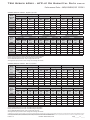
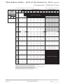
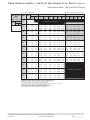
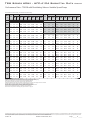
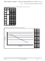
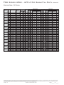
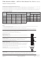
Performance Data – AHRI/ASHRAE/ISO 13256-1
ASHRAE/AHRI/ISO 13256-1. English (I-P) Units
Water Loop Heat Pump
Model
with ECM
Motor
Cooling 86°F
Ground Water Heat Pump
Heating 68°F
Capacity
Btuh
EER
Btuh/W
Capacity
Btuh
9,800
15.0
TSM12
11,600
TSM15
14,600
TSM18
Cooling 59°F
COP
Capacity
Btuh
EER
Btuh/W
Capacity
Btuh
12,900
5.4
11,700
24.5
14.7
16,000
5.2
13,600
15.9
17,500
5.3
16,800
18,000
15.2
22,200
5.1
TSM24
25,000
15.7
32,500
TSM30
28,000
15.1
TSM36
37,500
14.6
TSM09
Cooling 86°F
Cooling 77°F
Heating 32°F
COP
Capacity
Btuh
EER
Btuh/W
Capacity
Btuh
COP
10,300
4.5
10,500
17.8
7,400
3.4
23.8
12,900
4.4
12,300
17.2
9,600
3.4
25.6
14,500
4.5
15,500
18.8
11,000
3.6
20,000
23.5
17,700
4.4
18,500
17.3
13,200
3.3
5.1
29,500
25.3
26,000
4.5
26,500
18.5
18,200
3.5
34,500
5.0
31,500
22.9
28,500
4.4
29,000
17.6
22,200
3.6
44,000
5.0
42,500
22.6
36,000
4.3
38,500
16.5
28,000
3.5
Water Loop Heat Pump
Model
with PSC
Motor
Ground Loop Heat Pump
Heating 50°F
Ground Water Heat Pump
Heating 68°F
Capacity
Btuh
EER
Btuh/W
Capacity
Btuh
COP
TSM09
9,700
13.9
12,700
TSM12
11,400
13.8
16,000
TSM15
14,300
13.3
TSM18
17,300
TSM24
Cooling 59°F
Ground Loop Heat Pump
Heating 50°F
Capacity
Btuh
EER
Btuh/W
Capacity
Btuh
5.2
11,500
22.1
5.1
13,500
21.8
18,000
4.8
16,500
13.2
22,500
4.8
25,000
14.4
32,500
TSM30
27,500
13.4
TSM36
37,500
14.1
Cooling 77°F
Heating 32°F
COP
Capacity
Btuh
EER
Btuh/W
Capacity
Btuh
COP
10,400
4.3
10,300
16.2
7,600
3.2
13,000
4.3
12,200
16.0
9,700
3.3
20.5
14,500
4.1
15,200
15.6
11,500
3.3
20,000
20.0
18,000
4.0
18,400
15.1
13,500
3.2
4.9
29,000
22.5
26,500
4.3
26,500
16.8
18,400
3.4
34,500
4.7
31,000
19.5
28,500
4.1
28,500
15.2
22,000
3.3
44,500
4.9
42,500
21.5
36,500
4.3
38,500
16.2
28,500
3.4
Cooling capacities based upon 80.6°F DB, 66.2°F WB entering air temperature
Heating capacities based upon 68°F DB, 59°F WB entering air temperature
All units AHRI/ISO/ASHRAE 13256-1 rated on high speed motor TAP
All ratings based upon operation at lower voltage of dual voltage rated models
ASHRAE/AHRI/ISO 13256-1. Metric (S-I) Units
Water Loop Heat Pump
Model
with ECM
Motor
Cooling 30°C
Ground Water Heat Pump
Heating 20°C
Capacity
kW
EER
W/W
Capacity
kW
TSM09
2.87
4.4
TSM12
3.40
TSM15
4.28
TSM18
Cooling 15°C
COP
Capacity
kW
EER
W/W
Capacity
kW
3.78
5.4
3.37
7.2
4.3
4.69
5.2
3.99
4.7
5.13
5.3
4.92
5.28
4.5
6.51
5.1
TSM24
7.33
4.6
9.53
TSM30
8.21
4.4
TSM36
10.99
4.3
Cooling 30°C
Cooling 25°C
Heating 0°C
COP
Capacity
kW
EER
W/W
Capacity
kW
COP
3.02
4.5
3.08
5.2
2.17
3.4
7.0
3.78
4.4
3.60
5.0
2.81
3.4
7.5
4.25
4.5
4.54
5.5
3.22
3.6
5.86
6.9
5.19
4.4
5.42
5.1
3.87
3.3
5.1
8.65
7.4
7.62
4.5
7.77
5.4
5.33
3.5
10.11
5.0
9.23
6.7
8.35
4.4
8.50
5.2
6.51
3.6
12.90
5.0
12.46
6.6
10.55
4.3
11.28
4.8
8.21
3.5
Water Loop Heat Pump
Model
with PSC
Motor
Ground Loop Heat Pump
Heating 10°C
Ground Water Heat Pump
Heating 20°C
Capacity
kW
EER
W/W
Capacity
kW
TSM09
2.84
4.1
TSM12
3.34
4.0
TSM15
4.19
TSM18
Cooling 15°C
Ground Loop Heat Pump
Heating 10°C
COP
Capacity
kW
EER
W/W
Capacity
kW
3.72
5.2
3.37
6.5
4.69
5.1
3.96
6.4
3.9
5.28
4.8
4.84
5.07
3.9
6.59
4.8
TSM24
7.33
4.2
9.53
TSM30
8.06
3.9
TSM36
10.99
4.1
Cooling 25°C
Heating 0°C
COP
Capacity
kW
EER
W/W
Capacity
kW
COP
3.05
4.3
3.02
4.8
2.23
3.2
3.81
4.3
3.58
4.7
2.84
3.3
6.0
4.25
4.1
4.45
4.6
3.37
3.3
5.86
5.9
5.28
4.0
5.39
4.4
3.96
3.2
4.9
8.50
6.6
7.77
4.3
7.77
4.9
5.39
3.4
10.11
4.7
9.09
5.7
8.36
4.1
8.35
4.5
6.45
3.3
13.04
4.9
12.46
6.3
10.70
4.3
11.28
4.7
8.35
3.4
Cooling capacities based upon 27°C DB, 19°C WB entering air temperature
Heating capacities based upon 20°C DB, 15°C WB entering air temperature
All units AHRI/ISO/ASHRAE 13256-1 rated on high speed motor TAP
All ratings based upon operation at lower voltage of dual voltage rated models
ClimateMaster works continually to improve its products. As a result, the design and specifications of each product at the time of order may be changed without notice and may not be as described herein. Please contact ClimateMaster's Customer
Service Department at 1-405-745-6000 for specific information on the current design and specifications. Statements and other information contained herein are not express warranties and do not form the basis of any bargain between the parties,
but are merely ClimateMaster's opinion or commendation of its products. The latest version of this document is available at climatemaster.com.
LC994 - 13
Revised: 16 December, 2014
Page ______ of ______
TSM Series 60Hz - HFC-410A Submittal Data
Eng/I-P
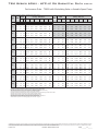
Performance Data – Selection Notes
For operation in the shaded area to determine if water
can be used in lieu of an antifreeze solution, the Leaving
Water Temperature (LWT) must be calculated. Flow must be
maintained to a level such that the LWT is maintained above
42°F [5.6°C] when the CXM/DXM2 JW3 jumper is not clipped
(see example below). Otherwise, appropriate levels (10° below
LWT, See IOM) of a proper antifreeze should be used in systems
with leaving water temperatures of 42°F [5.6°C] or below and
the JW3 jumper should be clipped. This is due to the potential
of the refrigerant temperature being as low as 32°F [0°C], which
may lead to a nuisance cutout due to the activation of the Low
Temperature Protection (LT1). JW3 should never be clipped for
standard range equipment or systems without antifreeze.
Example:
At 50°F EWT (Entering Water Temperature) and 1.5 gpm/ton, a
3 ton unit has a HE of 26,830 Btuh. To calculate LWT, rearrange
the formula for HE as follows:
HE = TD x GPM x 500, where HE = Heat of Extraction (Btuh);
TD = temperature difference (EWT - LWT) and GPM = U.S.
Gallons per Minute.
/67°F
W
Heating - EAT 70°F
HR
EER
HC
kW
HE
LAT
COP
23.28
2.31
15.72
85.9
3.0
mended
62
52.07
29.0
26.08
2.35
18.36
88.1
3.2
51
52.26
31.3
27.35
2.37
19.56
89.1
3.4
47
52.27
32.5
28.06
2.38
20.23
89.6
3.4
77
51.56
26.0
30.51
2.42
22.56
91.5
3.7
65
51.98
28.3
32.12
2.45
24.08
92.7
3.8
60
52.12
29.4
33.01
2.46
24.92
93.4
3.9
94
50.82
22.9
35.03
2.49
26.83
95.0
4.1
80
51.40
25.3
36.94
2.52
28.65
96.4
4.3
74
51.65
26.4
38.00
2.54
29.65
97.3
4.4
5
49.89
19.9
39.53
2.56
31.09
98.4
4.5
TD = HE / (GPM x 500)
TD = 26,830 / (4.5 x 500)
TD = 12°F
LWT = EWT - TD
LWT = 50 - 12 = 38°F - Requires appropriate antifreeze (Protect to 28°F), JW3 must be clipped, and extended range insulation option.
In this example, a higher flow rate will be required for EWTs of 50°F without antifreeze. At 3 gpm/ton, the calculation becomes:
(Note higher flow increases HE)
TD = 29,650 / (9GPMx500)
TD = 7°F
LWT = 50 - 7 = 43°F - Water is acceptable, do not clip JW3.
Performance Data Selection Notes – vFlow™ Models
Operation in Shaded Area: Closed Loop Application
For operation in the shaded area, appropriate levels of a proper antifreeze should be used in systems with leaving water
temperatures of 40°F or below and the JW3 jumper should be clipped. This is due to the potential of the refrigerant temperature
being as low as 32°F [0°C] with 40°F [4.4°C] LWT, which may lead to a nuisance cutout due to the activation of the Low Temperature
Protection. JW3 should never be clipped for systems without antifreeze.
Open Loop Application:
For operation in shaded area (below 40°F LWT) in open loop applications, ΔT (on DXM2) should be set such that the LWT (=EWT ΔT) doesn’t drop below 40°F. JW3 should NEVER be clipped for systems without antifreeze.
ClimateMaster works continually to improve its products. As a result, the design and specifications of each product at the time of order may be changed without notice and may not be as described herein. Please contact ClimateMaster's Customer
Service Department at 1-405-745-6000 for specific information on the current design and specifications. Statements and other information contained herein are not express warranties and do not form the basis of any bargain between the parties,
but are merely ClimateMaster's opinion or commendation of its products. The latest version of this document is available at climatemaster.com.
LC994 - 14
Revised: 16 December, 2014
Page ______ of ______
TSM Series 60Hz - HFC-410A Submittal Data
Eng/I-P
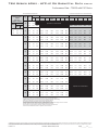
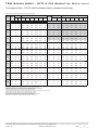
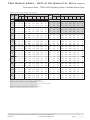
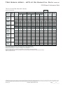
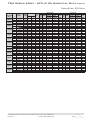
Performance Data – TSM09 with PSC Motor
400 CFM Nominal Airflow Heating, 350 CFM Nominal Airlfow Cooling
*WPD Adder for
Motorized Valve,
TSM09
(Cv = 3.0,
MOPD =200 psi)
WPD Adder
EWT
°F
20
GPM
PSI
FT
1.5
0.3
0.6
2.3
0.6
1.3
3.0
1.0
30
2.3
40
50
60
70
80
90
100
110
120
GPM
PSI
FT
Performance capacities shown in thousands of Btuh
Cooling - EAT 80/67°F
WPD*
TC
SC
Sens/Tot
Ratio
kW
Heating - EAT 70°F
HR
EER
HC
kW
HE
LAT
COP
6.33
0.65
3.96
75.6
2.8
1.5
1.6
2.3
1.8
3.0
5.7
13.2
1.5
1.1
2.6
13.08
9.05
0.69
0.41
14.61
32.5
7.36
0.66
4.95
76.9
3.2
2.3
1.8
4.0
12.95
8.80
0.68
0.39
14.43
33.4
7.70
0.67
5.28
77.3
3.3
8.63
0.67
0.39
14.29
33.5
7.89
0.67
5.46
77.5
3.4
Operation not recommended
3.0
4.7
10.7
12.82
1.5
0.8
1.9
12.97
9.21
0.71
0.44
14.64
29.6
8.84
0.68
6.39
78.7
3.8
2.3
1.7
3.9
13.08
9.14
0.70
0.42
14.65
31.6
9.31
0.68
6.84
79.3
3.9
9.06
0.69
0.41
14.62
32.4
3.0
4.1
9.6
13.08
9.57
0.68
7.09
79.6
4.0
1.5
0.5
1.1
12.59
9.16
0.73
0.49
14.42
25.9
10.39
0.69
7.89
80.6
4.4
2.3
1.6
3.7
12.87
9.21
0.72
0.46
14.58
28.3
10.98
0.69
8.47
81.3
4.6
9.21
0.71
0.44
14.63
29.5
3.0
3.6
8.4
12.97
11.31
0.69
8.79
81.7
4.7
1.5
0.4
1.0
12.00
8.95
0.75
0.55
14.03
22.1
11.95
0.70
9.42
82.5
5.0
2.3
1.5
3.5
12.40
9.09
0.73
0.51
14.29
24.5
12.65
0.70
10.11
83.4
5.2
3.0
4.0
9.3
12.57
9.15
0.73
0.49
14.41
25.8
13.04
0.70
10.49
83.9
5.4
1.5
0.4
0.9
11.28
8.64
0.77
0.61
13.52
18.6
13.50
0.71
10.94
84.4
5.5
8.84
0.75
0.57
13.84
20.7
2.3
1.4
3.3
11.74
14.28
0.71
11.71
85.4
5.8
3.0
3.0
7.0
11.96
8.93
0.75
0.55
14.00
21.9
14.71
0.71
12.13
85.9
6.0
1.5
0.3
0.8
10.46
8.27
0.79
0.68
12.94
15.6
14.98
0.71
12.40
86.3
6.1
2.3
1.3
3.1
10.95
8.49
0.78
0.64
13.29
17.3
15.81
0.72
13.22
87.3
6.4
3.0
3.1
7.1
11.20
8.60
0.77
0.62
13.46
18.3
16.24
0.72
13.65
87.8
6.6
7.87
0.82
0.75
12.33
12.9
1.5
0.3
0.7
9.61
16.36
0.72
13.76
88.0
6.6
2.3
1.5
3.5
10.09
8.10
0.80
0.71
12.68
14.4
17.18
0.72
14.57
89.0
6.9
8.21
0.79
0.69
12.86
15.2
17.58
0.72
14.98
89.5
7.1
10.8
3.0
3.1
7.2
10.34
1.5
0.1
0.2
8.76
7.49
0.86
0.83
11.73
2.3
1.2
2.9
9.21
7.69
0.84
0.79
12.05
11.9
7.80
0.83
0.77
12.22
12.5
3.0
2.8
6.4
9.45
1.5
0.1
0.2
7.96
7.16
0.90
0.90
11.18
9.0
2.8
8.36
7.32
0.88
0.86
11.45
9.9
7.41
0.86
0.84
11.60
10.3
2.3
1.2
3.0
2.7
6.2
8.57
1.5
0.1
0.2
7.26
6.93
0.95
0.97
10.72
7.6
7.03
0.93
0.94
10.93
8.3
7.09
0.91
0.92
11.05
8.6
2.3
1.2
2.7
7.59
3.0
2.6
6.0
7.77
Operation not recommended
Interpolation is permissible; extrapolation is not.
All entering air conditions are 80°F DB and 67°F WB in cooling, and 70°F DB in heating.
AHRI/ISO certified conditions are 80.6°F DB and 66.2°F WB in cooling and 68°F DB in heating.
Table does not reflect fan or pump power corrections for AHRI/ISO conditions.
All performance is based upon the lower voltage of dual voltage rated units.
Performance stated is at the rated power supply; performance may vary as the power supply varies from the rated.
Operation below 40°F EWT is based upon a 15% methanol antifreeze solution.
Operation below 60°F EWT requires optional insulated water/refrigerant circuit.
See performance correction tables for operating conditions other than those listed above.
See Performance Data Selection Notes for operation in the shaded areas.
ClimateMaster works continually to improve its products. As a result, the design and specifications of each product at the time of order may be changed without notice and may not be as described herein. Please contact ClimateMaster's Customer
Service Department at 1-405-745-6000 for specific information on the current design and specifications. Statements and other information contained herein are not express warranties and do not form the basis of any bargain between the parties,
but are merely ClimateMaster's opinion or commendation of its products. The latest version of this document is available at climatemaster.com.
LC994 - 15
Revised: 16 December, 2014
Page ______ of ______
TSM Series 60Hz - HFC-410A Submittal Data
Eng/I-P
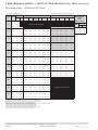
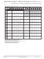
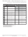
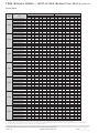
Performance Data – TSM12 with PSC Motor
500 CFM Nominal Airflow Heating, 400 CFM Nominal Airlfow Cooling
WPD*
EWT
°F
20
30
40
50
60
70
80
90
100
110
120
GPM
PSI
FT
1.8
4.1
2.6
6.3
3.5
9.4
21.7
1.8
3.4
7.9
Performance capacities shown in thousands of Btuh
Cooling - EAT 80/67°F
TC
SC
Sens/Tot
Ratio
kW
Heating - EAT 70°F
HR
EER
HC
kW
HE
LAT
COP
WPD Adder
Operation not recommended
15.44
9.92
0.64
0.45
16.96
*WPD Adder for
Motorized Valve,
TSM12
(Cv = 3.0,
MOPD =200 psi)
GPM
34.6
8.00
0.79
5.31
82.8
3.0
9.12
0.81
6.36
84.9
3.3
2.6
5.6
13.0
15.49
9.88
0.64
0.41
16.89
37.6
9.56
0.82
6.77
85.7
3.4
3.5
7.8
18.0
15.46
9.83
0.64
0.40
16.81
39.0
9.81
0.82
7.00
86.1
3.5
1.8
2.9
6.6
15.13
9.86
0.65
0.51
16.86
29.9
10.87
0.84
8.01
88.1
3.8
2.6
4.9
11.4
15.36
9.92
0.65
0.47
16.95
32.9
11.47
0.85
8.57
89.2
4.0
3.5
6.2
14.4
15.44
9.92
0.64
0.45
16.96
34.5
11.81
0.85
8.89
89.8
4.0
1.8
2.3
5.3
14.59
9.65
0.66
0.57
16.55
25.4
12.73
0.87
9.77
91.5
4.3
2.6
4.2
9.8
14.96
9.80
0.65
0.53
16.77
28.2
13.49
0.88
10.49
92.9
4.5
3.5
7.7
17.8
15.11
9.85
0.65
0.51
16.85
29.7
13.92
0.88
10.90
93.7
4.6
1.8
2.3
5.3
13.89
9.35
0.67
0.65
16.10
21.4
14.64
0.89
11.59
95.1
4.8
2.6
4.1
9.5
14.34
9.55
0.67
0.60
16.40
23.8
15.55
0.90
12.47
96.7
5.0
3.5
5.9
13.6
14.56
9.64
0.66
0.58
16.53
25.1
16.07
0.91
12.96
97.7
5.2
1.8
2.2
5.2
13.07
8.97
0.69
0.73
15.56
17.9
16.56
0.92
13.44
98.6
5.3
2.6
4.0
9.1
13.57
9.21
0.68
0.68
15.90
19.9
17.61
0.93
14.44
100.5
5.6
3.5
6.2
14.3
13.82
9.32
0.67
0.66
16.06
21.1
18.19
0.93
15.00
101.6
5.7
1.8
2.1
4.9
12.17
8.54
0.70
0.81
14.95
15.0
18.45
0.94
15.26
102.1
5.8
2.6
3.9
8.9
12.70
8.80
0.69
0.76
15.31
16.6
19.59
0.95
16.36
104.2
6.1
3.5
5.6
13.0
12.97
8.93
0.69
0.74
15.49
17.5
20.20
0.95
16.96
105.3
6.2
1.8
2.1
4.8
11.25
8.09
0.72
0.90
14.33
12.5
20.26
0.95
17.01
105.4
6.2
2.6
3.7
8.7
11.77
8.34
0.71
0.85
14.68
13.8
21.43
0.96
18.15
107.6
6.5
3.5
5.5
12.7
12.04
8.48
0.70
0.83
14.86
14.5
22.04
0.97
18.75
108.7
6.7
1.8
1.9
4.4
10.34
7.63
0.74
1.00
13.73
10.4
2.6
3.4
7.8
10.82
7.87
0.73
0.95
14.05
11.4
3.5
5.4
12.4
11.08
8.00
0.72
0.92
14.22
12.0
1.8
1.8
4.2
9.48
7.19
0.76
1.09
13.20
8.7
2.6
3.3
7.7
9.91
7.41
0.75
1.04
13.46
9.5
3.5
5.3
12.2
10.14
7.53
0.74
1.02
13.61
10.0
1.8
1.8
4.1
8.71
6.82
0.78
1.19
12.76
7.3
2.6
3.3
7.5
9.07
6.99
0.77
1.14
12.96
8.0
3.5
5.2
11.9
9.27
7.09
0.76
1.11
13.08
8.3
PSI
FT
1.8
0.3
0.8
2.6
0.8
1.7
3.5
1.4
3.1
Operation not recommended
Interpolation is permissible; extrapolation is not.
All entering air conditions are 80°F DB and 67°F WB in cooling, and 70°F DB in heating.
AHRI/ISO certified conditions are 80.6°F DB and 66.2°F WB in cooling and 68°F DB in heating.
Table does not reflect fan or pump power corrections for AHRI/ISO conditions.
All performance is based upon the lower voltage of dual voltage rated units.
Performance stated is at the rated power supply; performance may vary as the power supply varies from the rated.
Operation below 40°F EWT is based upon a 15% methanol antifreeze solution.
Operation below 60°F EWT requires optional insulated water/refrigerant circuit.
See performance correction tables for operating conditions other than those listed above.
See Performance Data Selection Notes for operation in the shaded areas.
ClimateMaster works continually to improve its products. As a result, the design and specifications of each product at the time of order may be changed without notice and may not be as described herein. Please contact ClimateMaster's Customer
Service Department at 1-405-745-6000 for specific information on the current design and specifications. Statements and other information contained herein are not express warranties and do not form the basis of any bargain between the parties,
but are merely ClimateMaster's opinion or commendation of its products. The latest version of this document is available at climatemaster.com.
LC994 - 16
Revised: 16 December, 2014
Page ______ of ______
TSM Series 60Hz - HFC-410A Submittal Data
Eng/I-P
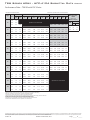
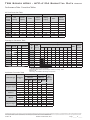
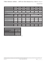
Performance Data – TSM15 with PSC Motor
600 CFM Nominal (Rated) Airflow
*WPD Adder for
Motorized Valve,
TSM15
(Cv = 4.7,
MOPD = 200 psi)
WPD Adder
EWT
°F
20
GPM
PSI
FT
2.3
0.2
0.5
3.4
0.5
1.2
4.5
0.9
2.1
30
40
50
60
70
80
90
100
110
120
Performance capacities shown in thousands of Btuh
WPD*
GPM
PSI
FT
Cooling - EAT 80/67°F
TC
SC
Sens/Tot
Ratio
kW
Heating - EAT 70°F
HR
EER
HC
kW
HE
LAT
COP
8.99
0.98
6.15
81.8
2.7
2.3
2.4
3.5
5.8
4.5
8.8
2.3
2.3
5.4
17.43
11.10
0.64
0.65
19.15
26.6
10.44
1.01
7.51
84.1
3.0
3.5
5.0
11.6
16.92
10.50
0.62
0.63
18.56
26.9
10.91
1.02
7.95
84.8
3.1
4.5
8.3
19.2
16.60
10.17
0.61
0.62
18.20
26.9
11.16
1.02
8.19
85.2
3.2
2.3
2.2
5.1
17.82
11.84
0.66
0.72
19.75
24.9
12.41
1.04
9.37
87.1
3.5
3.5
4.3
9.8
17.67
11.46
0.65
0.68
19.47
26.0
12.98
1.05
9.91
88.0
3.6
4.5
7.7
17.8
17.52
11.23
0.64
0.66
19.27
26.5
13.29
1.05
10.21
88.5
3.7
2.3
2.1
4.8
17.69
12.22
0.69
0.79
19.87
22.4
14.34
1.07
11.20
90.1
3.9
3.5
4.2
9.7
17.82
12.04
0.68
0.74
19.85
23.9
15.01
1.08
11.84
91.1
4.1
4.5
7.1
16.4
17.83
11.91
0.67
0.72
19.79
24.6
15.38
1.09
12.18
91.7
4.2
2.3
2.1
4.9
17.17
12.30
0.72
0.88
19.64
19.6
16.24
1.10
13.01
93.0
4.3
3.5
4.2
9.7
17.52
12.29
0.70
0.82
19.81
21.3
17.00
1.11
13.73
94.2
4.5
4.5
7.0
16.1
17.65
12.24
0.69
0.80
19.86
22.1
17.41
1.11
14.12
94.8
4.6
2.3
2.0
4.7
16.36
12.13
0.74
0.97
19.16
16.9
18.09
1.12
14.78
95.9
4.7
3.5
4.2
9.6
16.85
12.26
0.73
0.91
19.46
18.4
18.93
1.13
15.58
97.1
4.9
4.5
6.9
15.8
17.08
12.29
0.72
0.89
19.59
19.3
19.38
1.14
16.01
97.8
5.0
2.3
2.0
4.5
15.34
11.77
0.77
1.07
18.49
14.3
19.89
1.14
16.51
98.6
5.1
3.5
4.0
9.2
15.93
11.99
0.75
1.01
18.88
15.7
20.80
1.15
17.39
100.0
5.3
4.5
6.6
15.3
16.21
12.09
0.75
0.98
19.06
16.5
21.28
1.15
17.85
100.8
5.4
2.3
1.9
4.4
14.19
11.25
0.79
1.18
17.71
12.0
21.63
1.16
18.20
101.3
5.5
3.5
3.9
9.0
14.82
11.55
0.78
1.12
18.14
13.2
22.59
1.16
19.14
102.8
5.7
4.5
6.6
15.3
15.14
11.68
0.77
1.09
18.35
13.9
23.10
1.16
19.64
103.6
5.8
2.3
1.9
4.4
12.97
10.63
0.82
1.30
16.89
10.0
3.5
3.9
8.9
13.61
10.96
0.81
1.24
17.31
11.0
Operation not recommended
20.3
4.5
6.5
15.0
13.93
11.12
0.80
1.21
17.53
11.5
2.3
1.9
4.4
11.74
9.95
0.85
1.42
16.06
8.3
3.5
3.9
8.9
12.34
10.28
0.83
1.36
16.46
9.1
4.5
6.4
14.8
12.65
10.46
0.83
1.33
16.67
9.5
2.3
1.9
4.4
10.56
9.25
0.88
1.54
15.30
6.9
3.5
3.8
8.8
11.10
9.57
0.86
1.48
15.64
7.5
4.5
6.3
14.6
11.38
9.74
0.86
1.45
15.83
7.8
Operation not recommended
Interpolation is permissible; extrapolation is not.
All entering air conditions are 80°F DB and 67°F WB in cooling, and 70°F DB in heating.
AHRI/ISO certified conditions are 80.6°F DB and 66.2°F WB in cooling and 68°F DB in heating.
Table does not reflect fan or pump power corrections for AHRI/ISO conditions.
All performance is based upon the lower voltage of dual voltage rated units.
Performance stated is at the rated power supply; performance may vary as the power supply varies from the rated.
Operation below 40°F EWT is based upon a 15% methanol antifreeze solution.
Operation below 60°F EWT requires optional insulated water/refrigerant circuit.
See performance correction tables for operating conditions other than those listed above.
See Performance Data Selection Notes for operation in the shaded areas.
ClimateMaster works continually to improve its products. As a result, the design and specifications of each product at the time of order may be changed without notice and may not be as described herein. Please contact ClimateMaster's Customer
Service Department at 1-405-745-6000 for specific information on the current design and specifications. Statements and other information contained herein are not express warranties and do not form the basis of any bargain between the parties,
but are merely ClimateMaster's opinion or commendation of its products. The latest version of this document is available at climatemaster.com.
LC994 - 17
Revised: 16 December, 2014
Page ______ of ______
TSM Series 60Hz - HFC-410A Submittal Data
Eng/I-P
Performance Data – TSM18 with PSC Motor
685 CFM Nominal (Rated) Airflow
Performance capacities shown in thousands of Btuh
WPD*
EWT
°F
Cooling - EAT 80/67°F
GPM
20
30
40
50
60
70
80
90
100
110
120
PSI
FT
TC
SC
Sens/Tot
Ratio
kW
Heating - EAT 70°F
HR
3.4
2.6
5.1
4.7
6.8
7.2
16.7
3.4
2.2
5.1
23.79
15.72
0.66
0.77
25.90
5.1
4.2
9.7
23.88
15.52
0.65
0.73
6.8
6.7
15.4
23.89
15.38
0.64
3.4
1.9
4.3
23.35
15.80
5.1
3.8
8.7
23.61
6.8
5.4
12.5
23.71
3.4
1.5
3.5
5.1
3.3
7.7
6.8
4.4
3.4
1.5
5.1
6.8
EER
HC
kW
HE
LAT
COP
*WPD Adder for
Motorized Valve,
TSM18
(Cv =4.7,
MOPD = 200 psi)
WPD Adder
Operation not recommended
GPM
10.67
1.18
7.16
82.1
2.7
31.0
12.64
1.21
9.01
84.7
3.1
25.85
32.8
13.10
1.22
9.45
85.3
3.1
0.71
25.79
33.7
13.36
1.23
9.69
85.6
3.2
0.68
0.85
25.75
27.3
15.18
1.26
11.41
88.0
3.5
15.81
0.67
0.81
25.86
29.2
15.79
1.27
11.98
88.8
3.7
15.77
0.67
0.79
25.89
30.1
16.12
1.27
12.29
89.3
3.7
22.61
15.55
0.69
0.95
25.33
23.8
17.78
1.30
13.87
91.5
4.0
23.01
15.71
0.68
0.90
25.57
25.6
18.53
1.31
14.57
92.5
4.1
10.0
23.19
15.76
0.68
0.88
25.67
26.5
18.93
1.31
14.96
93.0
4.2
3.3
21.63
15.06
0.70
1.05
24.70
20.6
20.40
1.34
16.36
94.9
4.5
2.9
6.6
22.13
15.32
0.69
1.00
25.03
22.1
21.29
1.35
17.20
96.1
4.6
4.3
9.9
22.37
15.44
0.69
0.97
25.19
23.0
21.77
1.36
17.66
96.7
4.7
3.4
1.4
3.2
20.45
14.40
0.70
1.16
23.91
17.6
23.04
1.37
18.87
98.4
4.9
5.1
2.4
5.5
21.03
14.73
0.70
1.11
24.30
19.0
24.07
1.39
19.85
99.8
5.1
6.8
4.2
9.6
21.31
14.89
0.70
1.08
24.49
19.7
24.62
1.39
20.38
100.5
5.2
3.4
1.1
2.4
19.13
13.65
0.71
1.29
23.01
14.9
25.68
1.41
21.38
101.9
5.3
5.1
2.6
6.0
19.75
14.01
0.71
1.23
23.43
16.1
26.83
1.42
22.49
103.4
5.5
6.8
4.1
9.5
20.06
14.18
0.71
1.20
23.65
16.7
27.45
1.43
23.08
104.2
5.6
3.4
1.1
2.5
17.71
12.86
0.73
1.42
22.04
12.5
28.29
1.44
23.89
105.3
5.8
5.1
2.8
6.6
18.35
13.21
0.72
1.36
22.47
13.5
29.56
1.45
25.11
107.0
6.0
6.8
4.0
9.3
18.67
13.39
0.72
1.33
22.69
14.0
30.24
1.46
25.76
107.9
6.1
3.4
1.1
2.5
16.22
12.07
0.74
1.56
21.04
10.4
5.1
2.2
5.0
16.85
12.40
0.74
1.50
21.46
11.2
6.8
3.6
8.4
17.17
12.57
0.73
1.47
21.68
11.7
3.4
1.0
2.2
14.70
11.30
0.77
1.72
20.06
8.5
5.1
2.1
4.9
15.31
11.60
0.76
1.66
20.45
9.2
6.8
3.5
8.2
15.62
11.76
0.75
1.62
20.65
9.6
3.4
1.0
2.2
13.19
10.58
0.80
1.89
19.13
7.0
5.1
2.1
4.7
13.76
10.85
0.79
1.83
19.48
7.5
6.8
3.5
8.0
14.06
10.99
0.78
1.79
19.66
7.8
PSI
FT
3.4
0.5
1.2
5.1
1.2
2.7
6.8
2.1
4.8
Operation not recommended
Interpolation is permissible; extrapolation is not.
All entering air conditions are 80°F DB and 67°F WB in cooling, and 70°F DB in heating.
AHRI/ISO certified conditions are 80.6°F DB and 66.2°F WB in cooling and 68°F DB in heating.
Table does not reflect fan or pump power corrections for AHRI/ISO conditions.
All performance is based upon the lower voltage of dual voltage rated units.
Performance stated is at the rated power supply; performance may vary as the power supply varies from the rated.
Operation below 40°F EWT is based upon a 15% methanol antifreeze solution.
Operation below 60°F EWT requires optional insulated water/refrigerant circuit.
See performance correction tables for operating conditions other than those listed above.
See Performance Data Selection Notes for operation in the shaded areas.
ClimateMaster works continually to improve its products. As a result, the design and specifications of each product at the time of order may be changed without notice and may not be as described herein. Please contact ClimateMaster's Customer
Service Department at 1-405-745-6000 for specific information on the current design and specifications. Statements and other information contained herein are not express warranties and do not form the basis of any bargain between the parties,
but are merely ClimateMaster's opinion or commendation of its products. The latest version of this document is available at climatemaster.com.
LC994 - 18
Revised: 16 December, 2014
Page ______ of ______
TSM Series 60Hz - HFC-410A Submittal Data
Eng/I-P
Performance Data – TSM24 with PSC Motor
850 CFM Nominal (Rated) Airflow
*WPD Adder for
Motorized Valve,
TSM24
(Cv = 7.4,
MOPD = 200 psi)
GPM
WPD Adder
PSI
FT
4.0
0.3
0.7
6.0
0.7
1.5
8.0
1.2
2.7
Performance capacities shown in thousands of Btuh
WPD*
EWT
°F
20
30
40
50
60
70
80
90
100
110
120
Cooling - EAT 80/67°F
GPM
PSI
FT
TC
SC
Sens/Tot
Ratio
Heating - EAT 70°F
kW
HR
EER
HC
kW
HE
LAT
COP
17.55
1.73
12.11
87.1
3.0
36.72
31.8
19.10
1.72
13.69
88.8
3.3
4.0
0.8
6.0
2.5
8.0
5.2
12.1
4.0
0.9
2.1
6.0
2.3
5.3
34.11
21.76
0.64
0.99
37.03
34.4
19.80
1.72
14.39
89.5
3.4
8.0
5.0
11.4
34.31
21.80
0.64
0.96
37.13
35.7
20.20
1.72
14.79
90.0
3.4
4.0
0.7
1.6
32.53
21.15
0.65
1.16
36.03
28.0
21.81
1.73
16.37
91.7
3.7
6.0
2.3
5.2
33.29
21.48
0.65
1.09
36.54
30.6
22.77
1.74
17.30
92.8
3.8
8.0
4.6
10.7
33.62
21.61
0.64
1.05
36.75
32.0
23.31
1.74
17.82
93.3
3.9
4.0
0.5
1.1
31.23
20.51
0.66
1.28
35.13
24.4
24.83
1.76
19.27
95.0
4.1
6.0
2.2
5.1
32.14
20.97
0.65
1.20
35.76
26.9
26.06
1.78
20.44
96.3
4.3
8.0
4.3
9.9
32.57
21.17
0.65
1.16
36.05
28.2
26.75
1.79
21.10
97.1
4.4
4.0
0.4
1.0
29.72
19.72
0.66
1.42
34.11
20.9
28.05
1.82
22.32
98.5
4.5
6.0
2.0
4.6
30.74
20.26
0.66
1.33
34.80
23.2
29.55
1.84
23.72
100.1
4.7
8.0
4.0
9.3
31.23
20.51
0.66
1.28
35.14
24.4
30.38
1.86
24.49
101.0
4.8
4.0
0.4
0.9
28.06
18.82
0.67
1.59
33.02
17.7
31.39
1.88
25.43
102.1
4.9
6.0
1.8
4.1
29.14
19.41
0.67
1.48
33.72
19.7
33.13
1.92
27.03
104.0
5.1
8.0
3.8
8.7
29.67
19.70
0.66
1.43
34.08
20.8
34.08
1.94
27.91
105.0
5.1
4.0
0.3
0.7
26.31
17.83
0.68
1.78
31.93
14.7
34.76
1.96
28.53
105.8
5.2
6.0
1.7
4.0
27.40
18.45
0.67
1.66
32.60
16.5
36.67
2.01
30.28
107.9
5.4
8.0
3.5
8.1
27.96
18.76
0.67
1.60
32.95
17.5
37.70
2.03
31.23
109.0
5.4
4.0
0.3
0.7
24.51
16.80
0.69
2.01
30.92
12.2
38.05
2.04
31.54
109.4
5.5
6.0
1.8
4.2
25.59
17.43
0.68
1.87
31.52
13.7
40.07
2.10
33.38
111.5
5.6
41.13
2.12
34.34
112.7
5.7
Operation not recommended
33.57
21.59
0.64
1.06
8.0
3.2
7.4
26.15
17.74
0.68
1.80
31.84
14.5
4.0
0.3
0.6
22.72
15.77
0.69
2.28
30.05
9.9
6.0
1.6
3.7
23.76
16.37
0.69
2.12
30.54
11.2
8.0
3.0
6.9
24.30
16.68
0.69
2.04
30.81
11.9
4.0
0.2
0.5
21.00
14.77
0.70
2.60
29.41
8.1
6.0
1.6
3.7
21.96
15.33
0.70
2.42
29.74
9.1
8.0
2.9
6.7
22.47
15.62
0.70
2.33
29.95
9.7
4.0
0.2
0.4
19.39
13.84
0.71
2.97
29.07
6.5
6.0
1.0
2.3
20.26
14.34
0.71
2.76
29.21
7.3
8.0
2.8
6.6
20.73
14.61
0.70
2.66
29.33
7.8
Operation not recommended
Interpolation is permissible; extrapolation is not.
All entering air conditions are 80°F DB and 67°F WB in cooling, and 70°F DB in heating.
AHRI/ISO certified conditions are 80.6°F DB and 66.2°F WB in cooling and 68°F DB in heating.
Table does not reflect fan or pump power corrections for AHRI/ISO conditions.
All performance is based upon the lower voltage of dual voltage rated units.
Performance stated is at the rated power supply; performance may vary as the power supply varies from the rated.
Operation below 40°F EWT is based upon a 15% methanol antifreeze solution.
Operation below 60°F EWT requires optional insulated water/refrigerant circuit.
See performance correction tables for operating conditions other than those listed above.
See Performance Data Selection Notes for operation in the shaded areas.
ClimateMaster works continually to improve its products. As a result, the design and specifications of each product at the time of order may be changed without notice and may not be as described herein. Please contact ClimateMaster's Customer
Service Department at 1-405-745-6000 for specific information on the current design and specifications. Statements and other information contained herein are not express warranties and do not form the basis of any bargain between the parties,
but are merely ClimateMaster's opinion or commendation of its products. The latest version of this document is available at climatemaster.com.
LC994 - 19
Revised: 16 December, 2014
Page ______ of ______
TSM Series 60Hz - HFC-410A Submittal Data
Eng/I-P
Performance Data – TSM30 with PSC Motor
1000 CFM Nominal (Rated) Airflow
Performance capacities shown in thousands of Btuh
WPD*
EWT
°F
Cooling - EAT 80/67°F
GPM
20
30
40
50
60
70
80
90
100
110
120
PSI
FT
TC
SC
Sens/Tot
Ratio
kW
Heating - EAT 70°F
HR
4.0
1.2
6.0
2.5
8.0
5.2
12.1
4.0
0.9
2.1
33.05
22.48
0.68
1.30
36.75
6.0
2.3
5.3
32.29
21.97
0.68
1.23
35.77
8.0
5.0
11.4
31.79
21.64
0.68
1.20
4.0
0.7
1.6
33.55
22.84
0.68
6.0
2.3
5.2
33.34
22.68
8.0
4.6
10.7
33.12
22.53
4.0
0.5
1.1
33.29
6.0
2.2
5.1
33.53
8.0
4.3
9.9
4.0
0.4
6.0
2.0
8.0
4.0
EER
HC
kW
HE
LAT
COP
Operation not recommended
*WPD Adder for
Motorized Valve,
TSM30
(Cv = 7.4,
MOPD = 200 psi)
GPM
17.82
1.93
11.96
84.5
2.7
25.4
20.35
1.97
14.35
86.8
3.0
26.2
21.25
1.99
15.20
87.6
3.1
35.17
26.4
21.74
2.00
15.67
88.1
3.2
1.42
37.65
23.7
23.88
2.03
17.69
90.1
3.4
0.68
1.34
37.19
24.8
24.96
2.05
18.71
91.1
3.6
0.68
1.31
36.85
25.3
25.54
2.06
19.25
91.6
3.6
22.75
0.68
1.55
37.84
21.5
27.28
2.08
20.90
93.2
3.8
22.85
0.68
1.46
37.79
22.9
28.49
2.10
22.05
94.3
4.0
33.56
22.85
0.68
1.42
37.68
23.6
29.14
2.12
22.65
94.9
4.0
1.0
32.45
22.34
0.69
1.70
37.51
19.1
30.51
2.14
23.95
96.2
4.2
4.6
33.04
22.63
0.68
1.60
37.76
20.7
31.79
2.16
25.16
97.4
4.3
4.0
9.3
33.26
22.74
0.68
1.55
37.83
21.4
32.47
2.17
25.79
98.0
4.4
0.4
0.9
31.16
21.69
0.70
1.87
36.81
16.7
33.50
2.19
26.76
98.9
4.5
6.0
1.8
4.1
32.01
22.11
0.69
1.76
37.28
18.2
34.79
2.21
27.97
100.1
4.6
8.0
3.8
8.7
32.38
22.30
0.69
1.71
37.47
19.0
35.45
2.23
28.59
100.7
4.7
4.0
0.3
0.7
29.53
20.87
0.71
2.07
35.88
14.2
36.18
2.24
29.28
101.4
4.7
6.0
1.7
4.0
30.56
21.38
0.70
1.95
36.47
15.7
37.40
2.26
30.42
102.5
4.8
8.0
3.5
8.1
31.04
21.63
0.70
1.89
36.74
16.5
38.00
2.27
30.97
103.1
4.9
4.0
0.3
0.7
27.66
19.95
0.72
2.31
34.83
12.0
38.48
2.28
31.42
103.5
4.9
6.0
1.8
4.2
28.79
20.50
0.71
2.17
35.46
13.3
39.53
2.31
32.40
104.5
5.0
8.0
3.2
7.4
29.35
20.78
0.71
2.10
35.77
14.0
40.02
2.32
32.85
105.0
5.1
4.0
0.3
0.6
25.63
18.96
0.74
2.60
33.76
9.9
6.0
1.6
3.7
26.81
19.53
0.73
2.43
34.37
11.0
8.0
3.0
6.9
27.40
19.82
0.72
2.35
34.68
11.7
4.0
0.2
0.5
23.53
17.95
0.76
2.93
32.79
8.0
6.0
1.6
3.7
24.70
18.51
0.75
2.74
33.31
9.0
8.0
2.9
6.7
25.30
18.80
0.74
2.65
33.60
9.6
4.0
0.2
0.4
21.44
16.97
0.79
3.32
32.03
6.5
6.0
1.0
2.3
22.56
17.49
0.78
3.10
32.41
7.3
8.0
2.8
6.6
23.14
17.77
0.77
3.00
32.63
7.7
WPD Adder
PSI
FT
4.0
0.3
0.7
6.0
0.7
1.5
8.0
1.2
2.7
Operation not recommended
Interpolation is permissible; extrapolation is not.
All entering air conditions are 80°F DB and 67°F WB in cooling, and 70°F DB in heating.
AHRI/ISO certified conditions are 80.6°F DB and 66.2°F WB in cooling and 68°F DB in heating.
Table does not reflect fan or pump power corrections for AHRI/ISO conditions.
All performance is based upon the lower voltage of dual voltage rated units.
Performance stated is at the rated power supply; performance may vary as the power supply varies from the rated.
Operation below 40°F EWT is based upon a 15% methanol antifreeze solution.
Operation below 60°F EWT requires optional insulated water/refrigerant circuit.
See performance correction tables for operating conditions other than those listed above.
See Performance Data Selection Notes for operation in the shaded areas.
ClimateMaster works continually to improve its products. As a result, the design and specifications of each product at the time of order may be changed without notice and may not be as described herein. Please contact ClimateMaster's Customer
Service Department at 1-405-745-6000 for specific information on the current design and specifications. Statements and other information contained herein are not express warranties and do not form the basis of any bargain between the parties,
but are merely ClimateMaster's opinion or commendation of its products. The latest version of this document is available at climatemaster.com.
LC994 - 20
Revised: 16 December, 2014
Page ______ of ______
TSM Series 60Hz - HFC-410A Submittal Data
Eng/I-P
Performance Data – TSM36 with PSC Motor
1200 CFM Nominal (Rated) Airflow
*WPD Adder for
Motorized Valve,
TSM36
(Cv = 7.4,
MOPD = 200 psi)
GPM
WPD Adder
PSI
FT
4.5
0.4
0.9
6.8
0.8
1.9
9.0
1.5
3.4
Performance capacities shown in thousands of Btuh
WPD*
EWT
°F
20
30
40
50
60
70
80
90
100
110
120
Cooling - EAT 80/67°F
GPM
PSI
4.5
3.7
6.0
5.0
9.0
8.6
FT
TC
SC
Sens/Tot
Ratio
kW
Heating - EAT 70°F
HR
EER
HC
kW
HE
LAT
COP
23.28
2.31
15.72
85.9
3.0
Operation not recommended
19.8
4.5
2.8
6.4
46.36
30.52
0.66
1.62
52.07
29.0
26.08
2.35
18.36
88.1
3.2
6.0
3.8
8.8
46.90
30.81
0.66
1.51
52.26
31.3
27.35
2.37
19.56
89.1
3.4
9.0
7.4
17.0
47.08
30.90
0.66
1.47
52.27
32.5
28.06
2.38
20.23
89.6
3.4
4.5
1.8
4.3
45.35
29.95
0.66
1.77
51.56
26.0
30.51
2.42
22.56
91.5
3.7
6.0
2.6
5.9
46.16
30.41
0.66
1.65
51.98
28.3
32.12
2.45
24.08
92.7
3.8
9.0
7.0
16.3
46.49
30.59
0.66
1.60
52.12
29.4
33.01
2.46
24.92
93.4
3.9
4.5
0.9
2.1
44.01
29.22
0.66
1.94
50.82
22.9
35.03
2.49
26.83
95.0
4.1
6.0
2.4
5.6
45.06
29.79
0.66
1.80
51.40
25.3
36.94
2.52
28.65
96.4
4.3
9.0
4.7
10.7
45.52
30.05
0.66
1.74
51.65
26.4
38.00
2.54
29.65
97.3
4.4
4.5
0.9
2.0
42.36
28.34
0.67
2.15
49.89
19.9
39.53
2.56
31.09
98.4
4.5
6.0
2.3
5.3
43.62
29.01
0.67
1.99
50.60
22.2
41.72
2.60
33.15
100.1
4.7
9.0
4.4
10.3
44.20
29.32
0.66
1.91
50.93
23.3
42.91
2.62
34.28
101.0
4.8
4.5
0.8
1.8
40.44
27.36
0.68
2.40
48.83
17.0
43.95
2.64
35.25
101.8
4.9
6.0
2.2
5.1
41.88
28.09
0.67
2.21
49.62
19.2
46.34
2.69
37.48
103.7
5.1
9.0
4.3
10.0
42.56
28.45
0.67
2.12
50.00
20.3
47.62
2.71
38.67
104.7
5.1
4.5
0.8
1.8
38.26
26.28
0.69
2.71
47.70
14.3
48.21
2.73
39.21
105.1
5.2
6.0
2.1
4.9
39.85
27.06
0.68
2.48
48.52
16.3
50.69
2.78
41.50
107.0
5.3
9.0
4.2
9.6
40.62
27.45
0.68
2.38
48.93
17.3
52.00
2.82
42.69
108.0
5.4
4.5
0.8
1.8
35.85
25.12
0.70
3.08
46.54
11.8
52.19
2.82
42.87
108.2
5.4
6.0
2.1
4.9
37.57
25.94
0.69
2.81
47.35
13.5
54.65
2.90
45.08
110.1
5.5
9.0
4.0
9.3
38.41
26.35
0.69
2.69
47.77
14.5
55.89
2.94
46.17
111.0
5.6
4.5
0.7
1.7
33.20
23.86
0.72
3.52
45.40
9.6
6.0
2.1
4.8
35.03
24.73
0.71
3.21
46.17
11.1
9.0
3.9
9.1
35.93
25.16
0.70
3.06
46.58
11.9
4.5
0.7
1.5
30.35
22.50
0.74
4.04
44.33
7.6
6.0
2.0
4.6
32.28
23.42
0.73
3.68
45.03
8.9
9.0
3.9
8.9
33.23
23.87
0.72
3.51
45.41
9.6
4.5
0.6
1.5
27.29
21.02
0.77
4.66
43.37
6.0
6.0
1.9
4.4
29.31
22.00
0.75
4.24
43.98
7.0
9.0
3.6
8.4
30.30
22.48
0.74
4.05
44.31
7.6
Operation not recommended
Interpolation is permissible; extrapolation is not.
All entering air conditions are 80°F DB and 67°F WB in cooling, and 70°F DB in heating.
AHRI/ISO certified conditions are 80.6°F DB and 66.2°F WB in cooling and 68°F DB in heating.
Table does not reflect fan or pump power corrections for AHRI/ISO conditions.
All performance is based upon the lower voltage of dual voltage rated units.
Performance stated is at the rated power supply; performance may vary as the power supply varies from the rated.
Operation below 40°F EWT is based upon a 15% methanol antifreeze solution.
Operation below 60°F EWT requires optional insulated water/refrigerant circuit.
See performance correction tables for operating conditions other than those listed above.
See Performance Data Selection Notes for operation in the shaded areas.
ClimateMaster works continually to improve its products. As a result, the design and specifications of each product at the time of order may be changed without notice and may not be as described herein. Please contact ClimateMaster's Customer
Service Department at 1-405-745-6000 for specific information on the current design and specifications. Statements and other information contained herein are not express warranties and do not form the basis of any bargain between the parties,
but are merely ClimateMaster's opinion or commendation of its products. The latest version of this document is available at climatemaster.com.
LC994 - 21
Revised: 16 December, 2014
Page ______ of ______
TSM Series 60Hz - HFC-410A Submittal Data
Eng/I-P
Performance Data – TSM09 with ECM Motor
400 CFM Nominal Airflow Heating, 350 CFM Nominal Airflow Cooling
WPD
EWT
°F
GPM
20
30
40
50
60
70
80
90
100
110
120
PSI
FT
Performance capacities shown in thousands of Btuh
Cooling - EAT 80/67°F
TC
SC
Sens/Tot
Ratio
Heating - EAT 70°F
kW
HR
EER
HC
kW
HE
LAT
COP
6.18
0.65
3.96
75.6
2.8
1.5
1.6
2.3
1.8
3.0
5.7
13.2
1.5
1.1
2.6
13.23
9.05
0.68
0.41
14.61
32.5
7.21
0.66
4.95
76.9
3.2
2.3
1.8
4.0
13.10
8.80
0.67
0.39
14.43
33.4
7.55
0.67
5.28
77.3
3.3
3.0
4.7
10.7
12.97
8.63
0.67
0.39
14.29
33.5
7.74
0.67
5.46
77.5
1.5
0.8
1.9
13.12
9.21
0.70
0.44
14.64
29.6
8.69
0.68
6.39
78.7
2.3
1.7
3.9
13.23
9.14
0.69
0.42
14.65
31.6
9.16
0.68
6.84
79.3
3.9
3.0
4.1
9.6
13.23
9.06
0.69
0.41
14.62
32.4
9.42
0.68
7.09
79.6
4.0
1.5
0.5
1.1
12.74
9.16
0.72
0.49
14.42
25.9
10.24
0.69
7.89
80.6
4.4
2.3
1.6
3.7
13.02
9.21
0.71
0.46
14.58
28.3
10.83
0.69
8.47
81.3
4.6
3.0
3.6
8.4
13.12
9.21
0.70
0.44
14.63
29.5
11.16
0.69
8.79
81.7
4.7
1.5
0.4
1.0
12.15
8.95
0.74
0.55
14.03
22.1
11.80
0.70
9.42
82.5
5.0
2.3
1.5
3.5
12.55
9.09
0.72
0.51
14.29
24.5
12.50
0.70
10.11
83.4
5.2
3.0
4.0
9.3
12.72
9.15
0.72
0.49
14.41
25.8
12.89
0.70
10.49
83.9
5.4
1.5
0.4
0.9
11.43
8.64
0.76
0.61
13.52
18.6
13.35
0.71
10.94
84.4
5.5
2.3
1.4
3.3
11.89
8.84
0.74
0.57
13.84
20.7
14.13
0.71
11.71
85.4
5.8
3.0
3.0
7.0
12.11
8.93
0.74
0.55
14.00
21.9
14.56
0.71
12.13
85.9
6.0
1.5
0.3
0.8
10.61
8.27
0.78
0.68
12.94
15.6
14.83
0.71
12.40
86.3
6.1
2.3
1.3
3.1
11.10
8.49
0.76
0.64
13.29
17.3
15.66
0.72
13.22
87.3
6.4
3.0
3.1
7.1
11.35
8.60
0.76
0.62
13.46
18.3
16.09
0.72
13.65
87.8
6.6
1.5
0.3
0.7
9.76
7.87
0.81
0.75
12.33
12.9
16.21
0.72
13.76
88.0
6.6
2.3
1.5
3.5
10.24
8.10
0.79
0.71
12.68
14.4
17.03
0.72
14.57
89.0
6.9
3.0
3.1
7.2
10.49
8.21
0.78
0.69
12.86
15.2
17.43
0.72
14.98
89.5
7.1
1.5
0.1
0.2
8.91
7.49
0.84
0.83
11.73
10.8
2.3
1.2
2.9
9.36
7.69
0.82
0.79
12.05
11.9
3.0
2.8
6.4
9.60
7.80
0.81
0.77
12.22
12.5
1.5
0.1
0.2
8.11
7.16
0.88
0.90
11.18
9.0
2.3
1.2
2.8
8.51
7.32
0.86
0.86
11.45
9.9
3.0
2.7
6.2
8.72
7.41
0.85
0.84
11.60
10.3
1.5
0.1
0.2
7.41
6.93
0.93
0.97
10.72
7.6
2.3
1.2
2.7
7.74
7.03
0.91
0.94
10.93
8.3
3.0
2.6
6.0
7.92
7.09
0.90
0.92
11.05
8.6
*WPD Adder for
Motorized Valve,
TSM09
(Cv = 3.0,
MOPD =200 psi)
Operation not recommended
WPD Adder
GPM
PSI
FT
1.5
0.3
0.6
3.4
2.3
0.6
1.3
3.8
3.0
1.0
2.3
Operation not recommended
Interpolation is permissible; extrapolation is not.
All entering air conditions are 80°F DB and 67°F WB in cooling, and 70°F DB in heating.
AHRI/ISO certified conditions are 80.6°F DB and 66.2°F WB in cooling and 68°F DB in heating.
Table does not reflect fan or pump power corrections for AHRI/ISO conditions.
All performance is based upon the lower voltage of dual voltage rated units.
Performance stated is at the rated power supply; performance may vary as the power supply varies from the rated.
Operation below 40°F EWT is based upon a 15% methanol antifreeze solution.
Operation below 60°F EWT requires optional insulated water/refrigerant circuit.
See performance correction tables for operating conditions other than those listed above.
See Performance Data Selection Notes for operation in the shaded areas.
ClimateMaster works continually to improve its products. As a result, the design and specifications of each product at the time of order may be changed without notice and may not be as described herein. Please contact ClimateMaster's Customer
Service Department at 1-405-745-6000 for specific information on the current design and specifications. Statements and other information contained herein are not express warranties and do not form the basis of any bargain between the parties,
but are merely ClimateMaster's opinion or commendation of its products. The latest version of this document is available at climatemaster.com.
LC994 - 22
Revised: 16 December, 2014
Page ______ of ______
TSM Series 60Hz - HFC-410A Submittal Data
Eng/I-P
Performance Data – TSM12 with ECM Motor
500 CFM Nominal Airflow Heating, 400 CFM Nominal Airflow Cooling
*WPD Adder for
Motorized Valve,
TSM12
(Cv = 3.0,
MOPD =200 psi)
WPD
EWT
°F
SC
Sens/Tot
Ratio
kW
HR
EER
HC
kW
HE
LAT
COP
4.1
6.3
FT
3.5
9.4
21.7
7.76
0.77
5.13
83.9
2.9
1.8
3.4
7.9
15.67
10.25
0.65
0.41
17.07
38.2
8.92
0.79
6.23
86.3
3.3
2.7
5.6
13.0
15.78
10.15
0.64
0.37
17.05
42.4
9.25
0.79
6.54
87.0
3.4
3.5
7.8
18.0
15.79
10.06
0.64
0.35
17.00
44.5
9.43
0.80
6.71
87.4
3.5
1.8
2.9
6.6
15.30
10.23
0.67
0.47
16.92
32.2
10.50
0.81
7.72
89.6
3.8
2.7
4.9
11.4
15.56
10.27
0.66
0.43
17.04
36.0
10.92
0.82
8.12
90.4
3.9
3.5
6.2
14.4
15.66
10.25
0.65
0.41
17.07
38.0
11.16
0.83
8.34
90.9
4.0
1.8
2.3
5.3
14.74
10.05
0.68
0.54
16.60
27.1
12.11
0.84
9.24
92.9
4.2
2.7
4.2
9.8
15.12
10.18
0.67
0.50
16.82
30.3
12.62
0.85
9.71
93.9
4.3
3.5
7.7
17.8
15.28
10.23
0.67
0.48
16.91
32.1
12.90
0.86
9.97
94.5
4.4
1.8
2.3
5.3
14.04
9.75
0.69
0.62
16.16
22.7
13.72
0.87
10.74
96.2
4.6
2.7
4.1
9.5
14.49
9.95
0.69
0.57
16.45
25.3
14.30
0.89
11.28
97.4
4.7
3.5
5.9
13.6
14.71
10.04
0.68
0.55
16.58
26.8
14.62
0.89
11.57
98.0
4.8
1.8
2.2
5.2
13.23
9.37
0.71
0.70
15.62
18.9
15.30
0.91
12.21
99.4
4.9
2.7
4.0
9.1
13.73
9.60
0.70
0.65
15.95
21.1
15.93
0.92
12.79
100.7
5.1
3.5
6.2
14.3
13.98
9.72
0.70
0.63
16.12
22.3
16.27
0.93
13.11
101.4
5.2
1.8
2.1
4.9
12.35
8.94
0.72
0.78
15.02
15.8
16.81
0.94
13.61
102.5
5.3
2.7
3.9
8.9
12.87
9.19
0.71
0.73
15.38
17.5
17.47
0.95
14.23
103.9
5.4
3.5
5.6
13.0
13.14
9.32
0.71
0.71
15.56
18.5
17.82
0.96
14.56
104.6
5.5
1.8
2.1
4.8
11.43
8.49
0.74
0.87
14.40
13.1
18.22
0.96
14.93
105.4
5.5
2.7
3.7
8.7
11.95
8.74
0.73
0.82
14.75
14.5
18.88
0.98
15.55
106.8
5.7
3.5
5.5
12.7
12.22
8.87
0.73
0.80
14.93
15.3
19.22
0.98
15.87
107.5
5.7
1.8
0.3
0.8
2.6
0.8
1.7
1.4
TC
2.7
20
GPM
3.5
FT
Heating - EAT 70°F
1.8
WPD Adder
PSI
GPM
PSI
Performance capacities shown in thousands of Btuh
Cooling - EAT 80/67°F
30
3.1
40
50
60
70
80
90
100
110
120
Operation not recommended
1.8
1.9
4.4
10.50
8.05
0.77
0.96
13.78
10.9
2.7
3.4
7.8
11.00
8.29
0.75
0.91
14.11
12.1
3.5
5.4
12.4
11.26
8.41
0.75
0.89
14.29
12.7
1.8
1.8
4.2
9.59
7.65
0.80
1.05
13.19
9.1
2.7
3.3
7.7
10.05
7.85
0.78
1.01
13.49
10.0
3.5
5.3
12.2
10.30
7.96
0.77
0.98
13.65
10.5
1.8
1.8
4.1
8.74
7.29
0.83
1.15
12.66
7.6
2.7
3.3
7.5
9.15
7.46
0.82
1.10
12.91
8.3
3.5
5.2
11.9
9.37
7.55
0.81
1.08
13.05
8.7
Operation not recommended
Interpolation is permissible; extrapolation is not.
All entering air conditions are 80°F DB and 67°F WB in cooling, and 70°F DB in heating.
AHRI/ISO certified conditions are 80.6°F DB and 66.2°F WB in cooling and 68°F DB in heating.
Table does not reflect fan or pump power corrections for AHRI/ISO conditions.
All performance is based upon the lower voltage of dual voltage rated units.
Performance stated is at the rated power supply; performance may vary as the power supply varies from the rated.
Operation below 40°F EWT is based upon a 15% methanol antifreeze solution.
Operation below 60°F EWT requires optional insulated water/refrigerant circuit.
See performance correction tables for operating conditions other than those listed above.
See Performance Data Selection Notes for operation in the shaded areas.
ClimateMaster works continually to improve its products. As a result, the design and specifications of each product at the time of order may be changed without notice and may not be as described herein. Please contact ClimateMaster's Customer
Service Department at 1-405-745-6000 for specific information on the current design and specifications. Statements and other information contained herein are not express warranties and do not form the basis of any bargain between the parties,
but are merely ClimateMaster's opinion or commendation of its products. The latest version of this document is available at climatemaster.com.
LC994 - 23
Revised: 16 December, 2014
Page ______ of ______
TSM Series 60Hz - HFC-410A Submittal Data
Eng/I-P
Performance Data – TSM15 with ECM Motor
600 CFM Nominal (Rated) Airflow
Performance capacities shown in thousands of Btuh
WPD
EWT
°F
20
30
40
50
60
70
80
90
100
110
120
Cooling - EAT 80/67°F
GPM
PSI
FT
TC
SC
Sens/Tot
Ratio
kW
Heating - EAT 70°F
HR
EER
HC
kW
HE
LAT
COP
8.69
0.83
6.15
81.8
3.2
2.3
2.4
3.5
5.8
4.5
8.8
20.3
2.3
2.3
5.4
17.43
11.10
0.64
0.50
19.15
34.5
10.14
0.86
7.51
84.1
3.6
3.5
5.0
11.6
16.92
10.50
0.62
0.48
18.56
35.4
10.61
0.87
7.95
84.8
3.7
4.5
8.3
19.2
16.60
10.17
0.61
0.47
18.20
35.5
10.86
0.87
8.19
85.2
3.8
2.3
2.2
3.5
4.5
*WPD Adder for
Motorized Valve,
TSM15
(Cv = 4.7,
MOPD = 200 psi)
Operation not recommended
WPD Adder
5.1
17.82
11.84
0.66
0.57
19.75
31.5
12.11
0.89
9.37
87.1
4.1
4.3
9.8
17.67
11.46
0.65
0.53
19.47
33.4
12.68
0.90
9.91
88.0
4.2
7.7
17.8
17.52
11.23
0.64
0.51
19.27
34.2
12.99
0.90
10.21
88.5
4.3
2.3
2.1
4.8
17.69
12.22
0.69
0.64
19.87
27.7
14.04
0.92
11.20
90.1
4.6
3.5
4.2
9.7
17.82
12.04
0.68
0.59
19.85
30.0
14.71
0.93
11.84
91.1
4.7
4.5
7.1
16.4
17.83
11.91
0.67
0.57
19.79
31.1
15.08
0.94
12.18
91.7
4.8
2.3
2.1
4.9
17.17
12.30
0.72
0.73
19.64
23.7
15.94
0.95
13.01
93.0
5.0
3.5
4.2
9.7
17.52
12.29
0.70
0.67
19.81
26.0
16.70
0.96
13.73
94.2
5.2
4.5
7.0
16.1
17.65
12.24
0.69
0.65
19.86
27.2
17.11
0.96
14.12
94.8
5.3
2.3
2.0
4.7
16.36
12.13
0.74
0.82
19.16
20.0
17.79
0.97
14.78
95.9
5.5
3.5
4.2
9.6
16.85
12.26
0.73
0.76
19.46
22.1
18.63
0.98
15.58
97.1
5.7
4.5
6.9
15.8
17.08
12.29
0.72
0.74
19.59
23.2
19.08
0.99
16.01
97.8
5.8
2.3
2.0
4.5
15.34
11.77
0.77
0.92
18.49
16.6
19.59
0.99
16.51
98.6
5.9
3.5
4.0
9.2
15.93
11.99
0.75
0.86
18.88
18.4
20.50
1.00
17.39
100.0
6.1
4.5
6.6
15.3
16.21
12.09
0.75
0.83
19.06
19.4
20.98
1.00
17.85
100.8
6.2
2.3
1.9
4.4
14.19
11.25
0.79
1.03
17.71
13.8
21.33
1.01
18.20
101.3
6.3
3.5
3.9
9.0
14.82
11.55
0.78
0.97
18.14
15.3
22.29
1.01
19.14
102.8
6.5
4.5
6.6
15.3
15.14
11.68
0.77
0.94
18.35
16.1
22.80
1.01
19.64
103.6
6.7
2.3
1.9
4.4
12.97
10.63
0.82
1.15
16.89
11.3
3.5
3.9
8.9
13.61
10.96
0.81
1.09
17.31
12.5
4.5
6.5
15.0
13.93
11.12
0.80
1.06
17.53
13.2
2.3
1.9
4.4
11.74
9.95
0.85
1.27
16.06
9.3
3.5
3.9
8.9
12.34
10.28
0.83
1.21
16.46
10.2
4.5
6.4
14.8
12.65
10.46
0.83
1.18
16.67
10.8
2.3
1.9
4.4
10.56
9.25
0.88
1.39
15.30
7.6
3.5
3.8
8.8
11.10
9.57
0.86
1.33
15.64
8.3
4.5
6.3
14.6
11.38
9.74
0.86
1.30
15.83
8.7
GPM
PSI
FT
2.3
0.2
0.5
3.4
0.5
1.2
4.5
0.9
2.1
Operation not recommended
Interpolation is permissible; extrapolation is not.
All entering air conditions are 80°F DB and 67°F WB in cooling, and 70°F DB in heating.
AHRI/ISO certified conditions are 80.6°F DB and 66.2°F WB in cooling and 68°F DB in heating.
Table does not reflect fan or pump power corrections for AHRI/ISO conditions.
All performance is based upon the lower voltage of dual voltage rated units.
Performance stated is at the rated power supply; performance may vary as the power supply varies from the rated.
Operation below 40°F EWT is based upon a 15% methanol antifreeze solution.
Operation below 60°F EWT requires optional insulated water/refrigerant circuit.
See performance correction tables for operating conditions other than those listed above.
See Performance Data Selection Notes for operation in the shaded areas.
ClimateMaster works continually to improve its products. As a result, the design and specifications of each product at the time of order may be changed without notice and may not be as described herein. Please contact ClimateMaster's Customer
Service Department at 1-405-745-6000 for specific information on the current design and specifications. Statements and other information contained herein are not express warranties and do not form the basis of any bargain between the parties,
but are merely ClimateMaster's opinion or commendation of its products. The latest version of this document is available at climatemaster.com.
LC994 - 24
Revised: 16 December, 2014
Page ______ of ______
TSM Series 60Hz - HFC-410A Submittal Data
Eng/I-P
Performance Data – TSM18 with ECM Motor
700 CFM Nominal (Rated) Airflow
*WPD Adder for
Motorized Valve,
TSM18
(Cv =4.7,
MOPD = 200 psi)
WPD Adder
WPD
EWT
°F
20
GPM
PSI
FT
3.4
0.5
1.2
5.1
1.2
2.7
6.8
2.1
4.8
Performance capacities shown in thousands of Btuh
30
40
50
60
70
80
90
100
110
120
Cooling - EAT 80/67°F
GPM
PSI
FT
TC
SC
Sens/Tot
Ratio
kW
Heating - EAT 70°F
HR
EER
HC
kW
HE
LAT
COP
10.67
1.03
7.16
82.1
3.0
38.5
12.64
1.06
9.01
84.7
3.5
3.4
5.1
2.6
4.7
6.8
7.2
16.7
3.4
2.2
5.1
5.1
4.2
9.7
23.88
15.52
0.65
0.58
25.85
41.4
13.10
1.07
9.45
85.3
3.6
6.8
6.7
15.4
23.89
15.38
0.64
0.56
25.79
42.8
13.36
1.08
9.69
85.6
3.6
3.4
1.9
4.3
23.35
15.80
0.68
0.70
25.75
33.2
15.18
1.11
11.41
88.0
4.0
5.1
3.8
8.7
23.61
15.81
0.67
0.66
25.86
35.8
15.79
1.12
11.98
88.8
4.1
6.8
5.4
12.5
23.71
15.77
0.67
0.64
25.89
37.2
16.12
1.12
12.29
89.3
4.2
3.4
1.5
3.5
22.61
15.55
0.69
0.80
25.33
28.3
17.78
1.15
13.87
91.5
4.5
5.1
3.3
7.7
23.01
15.71
0.68
0.75
25.57
30.7
18.53
1.16
14.57
92.5
4.7
6.8
4.4
10.0
23.19
15.76
0.68
0.73
25.67
31.9
18.93
1.16
14.96
93.0
4.8
3.4
1.5
3.3
21.63
15.06
0.70
0.90
24.70
24.0
20.40
1.19
16.36
94.9
5.0
5.1
2.9
6.6
22.13
15.32
0.69
0.85
25.03
26.0
21.29
1.20
17.20
96.1
5.2
6.8
4.3
9.9
22.37
15.44
0.69
0.82
25.19
27.1
21.77
1.21
17.66
96.7
5.3
3.4
1.4
3.2
20.45
14.40
0.70
1.01
23.91
20.2
23.04
1.22
18.87
98.4
5.5
5.1
2.4
5.5
21.03
14.73
0.70
0.96
24.30
21.9
24.07
1.24
19.85
99.8
5.7
6.8
4.2
9.6
21.31
14.89
0.70
0.93
24.49
22.9
24.62
1.24
20.38
100.5
5.8
3.4
1.1
2.4
19.13
13.65
0.71
1.14
23.01
16.8
25.68
1.26
21.38
101.9
6.0
5.1
2.6
6.0
19.75
14.01
0.71
1.08
23.43
18.3
26.83
1.27
22.49
103.4
6.2
6.8
4.1
9.5
20.06
14.18
0.71
1.05
23.65
19.1
27.45
1.28
23.08
104.2
6.3
3.4
1.1
2.5
17.71
12.86
0.73
1.27
22.04
13.9
28.29
1.29
23.89
105.3
6.4
5.1
2.8
6.6
18.35
13.21
0.72
1.21
22.47
15.2
29.56
1.30
25.11
107.0
6.6
6.8
4.0
9.3
18.67
13.39
0.72
1.18
22.69
15.8
30.24
1.31
25.76
107.9
6.8
Operation not recommended
23.79
15.72
0.66
0.62
25.90
3.4
1.1
2.5
16.22
12.07
0.74
1.41
21.04
11.5
5.1
2.2
5.0
16.85
12.40
0.74
1.35
21.46
12.5
6.8
3.6
8.4
17.17
12.57
0.73
1.32
21.68
13.0
3.4
1.0
2.2
14.70
11.30
0.77
1.57
20.06
9.3
5.1
2.1
4.9
15.31
11.60
0.76
1.51
20.45
10.2
6.8
3.5
8.2
15.62
11.76
0.75
1.47
20.65
10.6
3.4
1.0
2.2
13.19
10.58
0.80
1.74
19.13
7.6
5.1
2.1
4.7
13.76
10.85
0.79
1.68
19.48
8.2
6.8
3.5
8.0
14.06
10.99
0.78
1.64
19.66
8.6
Operation not recommended
Interpolation is permissible; extrapolation is not.
All entering air conditions are 80°F DB and 67°F WB in cooling, and 70°F DB in heating.
AHRI/ISO certified conditions are 80.6°F DB and 66.2°F WB in cooling and 68°F DB in heating.
Table does not reflect fan or pump power corrections for AHRI/ISO conditions.
All performance is based upon the lower voltage of dual voltage rated units.
Performance stated is at the rated power supply; performance may vary as the power supply varies from the rated.
Operation below 40°F EWT is based upon a 15% methanol antifreeze solution.
Operation below 60°F EWT requires optional insulated water/refrigerant circuit.
See performance correction tables for operating conditions other than those listed above.
See Performance Data Selection Notes for operation in the shaded areas.
ClimateMaster works continually to improve its products. As a result, the design and specifications of each product at the time of order may be changed without notice and may not be as described herein. Please contact ClimateMaster's Customer
Service Department at 1-405-745-6000 for specific information on the current design and specifications. Statements and other information contained herein are not express warranties and do not form the basis of any bargain between the parties,
but are merely ClimateMaster's opinion or commendation of its products. The latest version of this document is available at climatemaster.com.
LC994 - 25
Revised: 16 December, 2014
Page ______ of ______
TSM Series 60Hz - HFC-410A Submittal Data
Eng/I-P
Performance Data – TSM24 with ECM Motor
850 CFM Nominal (Rated) Airflow
Performance capacities shown in thousands of Btuh
WPD
EWT
°F
Cooling - EAT 80/67°F
GPM
20
30
40
50
60
70
80
90
100
110
120
PSI
FT
TC
SC
Sens/Tot
Ratio
kW
Heating - EAT 70°F
HR
EER
HC
kW
HE
LAT
COP
17.55
1.60
12.11
87.1
3.2
4.0
6.0
3.9
2.5
8.0
5.2
12.1
4.0
0.9
2.1
33.57
21.59
0.64
0.92
36.72
36.4
19.10
1.59
13.69
88.8
3.5
6.0
2.3
5.3
34.11
21.76
0.64
0.86
37.03
39.8
19.80
1.59
14.39
89.5
3.7
8.0
5.0
11.4
34.31
21.80
0.64
0.83
37.13
41.6
20.20
1.59
14.79
90.0
3.7
4.0
0.7
6.0
8.0
*WPD Adder for
Motorized Valve,
TSM24
(Cv = 7.4,
MOPD = 200 psi)
Operation not recommended
1.6
32.53
21.15
0.65
1.03
36.03
31.7
21.81
1.59
16.37
91.7
4.0
2.3
5.2
33.29
21.48
0.65
0.95
36.54
35.0
22.77
1.60
17.30
92.8
4.2
4.6
10.7
33.62
21.61
0.64
0.92
36.75
36.7
23.31
1.61
17.82
93.3
4.2
4.0
0.5
1.1
31.23
20.51
0.66
1.15
35.13
27.3
24.83
1.63
19.27
95.0
4.5
6.0
2.2
5.1
32.14
20.97
0.65
1.06
35.76
30.3
26.06
1.65
20.44
96.3
4.6
8.0
4.3
9.9
32.57
21.17
0.65
1.02
36.05
31.9
26.75
1.66
21.10
97.1
4.7
4.0
0.4
1.0
29.72
19.72
0.66
1.29
34.11
23.1
28.05
1.68
22.32
98.5
4.9
6.0
2.0
4.6
30.74
20.26
0.66
1.19
34.80
25.8
29.55
1.71
23.72
100.1
5.1
8.0
4.0
9.3
31.23
20.51
0.66
1.15
35.14
27.3
30.38
1.73
24.49
101.0
5.2
4.0
0.4
0.9
28.06
18.82
0.67
1.45
33.02
19.3
31.39
1.75
25.43
102.1
5.3
6.0
1.8
4.1
29.14
19.41
0.67
1.34
33.72
21.7
33.13
1.79
27.03
104.0
5.4
8.0
3.8
8.7
29.67
19.70
0.66
1.29
34.08
23.0
34.08
1.81
27.91
105.0
5.5
4.0
0.3
0.7
26.31
17.83
0.68
1.65
31.93
16.0
34.76
1.82
28.53
105.8
5.6
6.0
1.7
4.0
27.40
18.45
0.67
1.52
32.60
18.0
36.67
1.87
30.28
107.9
5.7
8.0
3.5
8.1
27.96
18.76
0.67
1.46
32.95
19.1
37.70
1.90
31.23
109.0
5.8
4.0
0.3
0.7
24.51
16.80
0.69
1.88
30.92
13.0
38.05
1.91
31.54
109.4
5.8
6.0
1.8
4.2
25.59
17.43
0.68
1.74
31.52
14.7
40.07
1.96
33.38
111.5
6.0
8.0
3.2
7.4
26.15
17.74
0.68
1.67
31.84
15.7
41.13
1.99
34.34
112.7
6.1
4.0
0.3
0.6
22.72
15.77
0.69
2.15
30.05
10.6
6.0
1.6
3.7
23.76
16.37
0.69
1.99
30.54
12.0
8.0
3.0
6.9
24.30
16.68
0.69
1.91
30.81
12.7
4.0
0.2
0.5
21.00
14.77
0.70
2.47
29.41
8.5
6.0
1.6
3.7
21.96
15.33
0.70
2.28
29.74
9.6
8.0
2.9
6.7
22.47
15.62
0.70
2.19
29.95
10.3
4.0
0.2
0.4
19.39
13.84
0.71
2.84
29.07
6.8
6.0
1.0
2.3
20.26
14.34
0.71
2.62
29.21
7.7
8.0
2.8
6.6
20.73
14.61
0.70
2.52
29.33
8.2
GPM
WPD Adder
PSI
FT
4.0
0.3
0.7
6.0
0.7
1.5
8.0
1.2
2.7
Operation not recommended
Interpolation is permissible; extrapolation is not.
All entering air conditions are 80°F DB and 67°F WB in cooling, and 70°F DB in heating.
AHRI/ISO certified conditions are 80.6°F DB and 66.2°F WB in cooling and 68°F DB in heating.
Table does not reflect fan or pump power corrections for AHRI/ISO conditions.
All performance is based upon the lower voltage of dual voltage rated units.
Performance stated is at the rated power supply; performance may vary as the power supply varies from the rated.
Operation below 40°F EWT is based upon a 15% methanol antifreeze solution.
Operation below 60°F EWT requires optional insulated water/refrigerant circuit.
See performance correction tables for operating conditions other than those listed above.
See Performance Data Selection Notes for operation in the shaded areas.
ClimateMaster works continually to improve its products. As a result, the design and specifications of each product at the time of order may be changed without notice and may not be as described herein. Please contact ClimateMaster's Customer
Service Department at 1-405-745-6000 for specific information on the current design and specifications. Statements and other information contained herein are not express warranties and do not form the basis of any bargain between the parties,
but are merely ClimateMaster's opinion or commendation of its products. The latest version of this document is available at climatemaster.com.
LC994 - 26
Revised: 16 December, 2014
Page ______ of ______
TSM Series 60Hz - HFC-410A Submittal Data
Eng/I-P
Performance Data – TSM30 with ECM Motor
1000 CFM Nominal (Rated) Airflow
*WPD Adder for
Motorized Valve,
TSM30
(Cv = 7.4,
MOPD = 200 psi)
GPM
WPD Adder
PSI
0.3
0.7
6.0
0.7
1.5
8.0
1.2
2.7
Cooling - EAT 80/67°F
EWT
°F
GPM
4.0
1.2
20
6.0
2.5
8.0
5.2
12.1
4.0
0.9
2.1
33.05
22.48
0.68
1.08
6.0
2.3
5.3
32.29
21.97
0.68
8.0
5.0
11.4
31.79
21.64
0.68
4.0
0.7
1.6
33.55
22.84
6.0
2.3
5.2
33.34
8.0
4.6
10.7
4.0
0.5
6.0
FT
4.0
Performance capacities shown in thousands of Btuh
WPD
30
40
50
60
70
80
90
100
110
120
PSI
FT
TC
SC
Sens/Tot
Ratio
kW
Heating - EAT 70°F
HR
EER
HC
kW
HE
LAT
COP
17.82
1.72
11.96
84.5
3.0
36.75
30.5
20.35
1.76
14.35
86.8
3.4
1.02
35.77
31.7
21.25
1.77
15.20
87.6
3.5
0.99
35.17
32.2
21.74
1.78
15.67
88.1
3.6
0.68
1.20
37.65
27.9
23.88
1.81
17.69
90.1
3.9
22.68
0.68
1.13
37.19
29.6
24.96
1.83
18.71
91.1
4.0
33.12
22.53
0.68
1.09
36.85
30.3
25.54
1.84
19.25
91.6
4.1
1.1
33.29
22.75
0.68
1.33
37.84
25.0
27.28
1.87
20.90
93.2
4.3
2.2
5.1
33.53
22.85
0.68
1.25
37.79
26.9
28.49
1.89
22.05
94.3
4.4
8.0
4.3
9.9
33.56
22.85
0.68
1.21
37.68
27.8
29.14
1.90
22.65
94.9
4.5
4.0
0.4
1.0
32.45
22.34
0.69
1.48
37.51
21.9
30.51
1.92
23.95
96.2
4.6
6.0
2.0
4.6
33.04
22.63
0.68
1.38
37.76
23.9
31.79
1.95
25.16
97.4
4.8
8.0
4.0
9.3
33.26
22.74
0.68
1.34
37.83
24.9
32.47
1.96
25.79
98.0
4.9
4.0
0.4
0.9
31.16
21.69
0.70
1.65
36.81
18.8
33.50
1.97
26.76
98.9
5.0
6.0
1.8
4.1
32.01
22.11
0.69
1.54
37.28
20.7
34.79
2.00
27.97
100.1
5.1
8.0
3.8
8.7
32.38
22.30
0.69
1.49
37.47
21.7
35.45
2.01
28.59
100.7
5.2
4.0
0.3
0.7
29.53
20.87
0.71
1.86
35.88
15.9
36.18
2.02
29.28
101.4
5.2
6.0
1.7
4.0
30.56
21.38
0.70
1.73
36.47
17.7
37.40
2.05
30.42
102.5
5.4
8.0
3.5
8.1
31.04
21.63
0.70
1.67
36.74
18.6
38.00
2.06
30.97
103.1
5.4
4.0
0.3
0.7
27.66
19.95
0.72
2.10
34.83
13.2
38.48
2.07
31.42
103.5
5.5
6.0
1.8
4.2
28.79
20.50
0.71
1.95
35.46
14.7
39.53
2.09
32.40
104.5
5.5
8.0
3.2
7.4
29.35
20.78
0.71
1.88
35.77
15.6
40.02
2.10
32.85
105.0
5.6
4.0
0.3
0.6
25.63
18.96
0.74
2.38
33.76
10.8
6.0
1.6
3.7
26.81
19.53
0.73
2.21
34.37
12.1
8.0
3.0
6.9
27.40
19.82
0.72
2.13
34.68
12.8
4.0
0.2
0.5
23.53
17.95
0.76
2.71
32.79
8.7
6.0
1.6
3.7
24.70
18.51
0.75
2.52
33.31
9.8
8.0
2.9
6.7
25.30
18.80
0.74
2.43
33.60
10.4
4.0
0.2
0.4
21.44
16.97
0.79
3.10
32.03
6.9
6.0
1.0
2.3
22.56
17.49
0.78
2.89
32.41
7.8
8.0
2.8
6.6
23.14
17.77
0.77
2.78
32.63
8.3
Operation not recommended
Operation not recommended
Interpolation is permissible; extrapolation is not.
All entering air conditions are 80°F DB and 67°F WB in cooling, and 70°F DB in heating.
AHRI/ISO certified conditions are 80.6°F DB and 66.2°F WB in cooling and 68°F DB in heating.
Table does not reflect fan or pump power corrections for AHRI/ISO conditions.
All performance is based upon the lower voltage of dual voltage rated units.
Performance stated is at the rated power supply; performance may vary as the power supply varies from the rated.
Operation below 40°F EWT is based upon a 15% methanol antifreeze solution.
Operation below 60°F EWT requires optional insulated water/refrigerant circuit.
See performance correction tables for operating conditions other than those listed above.
See Performance Data Selection Notes for operation in the shaded areas.
ClimateMaster works continually to improve its products. As a result, the design and specifications of each product at the time of order may be changed without notice and may not be as described herein. Please contact ClimateMaster's Customer
Service Department at 1-405-745-6000 for specific information on the current design and specifications. Statements and other information contained herein are not express warranties and do not form the basis of any bargain between the parties,
but are merely ClimateMaster's opinion or commendation of its products. The latest version of this document is available at climatemaster.com.
LC994 - 27
Revised: 16 December, 2014
Page ______ of ______
TSM Series 60Hz - HFC-410A Submittal Data
Eng/I-P
Performance Data – TSM36 with ECM Motor
1200 CFM Nominal (Rated) Airflow
Performance capacities shown in thousands of Btuh
WPD
EWT
°F
GPM
PSI
4.5
20
30
40
50
60
70
80
90
100
110
120
Cooling - EAT 80/67°F
FT
TC
SC
Sens/Tot
Ratio
kW
Heating - EAT 70°F
HR
EER
HC
kW
HE
LAT
COP
23.28
2.22
15.72
85.9
3.1
3.7
6.0
5.0
9.0
8.6
19.8
4.5
2.8
6.4
46.26
30.11
0.65
1.53
51.50
30.2
26.08
2.26
18.36
88.1
3.4
6.0
3.8
8.8
46.26
30.05
0.65
1.46
51.25
31.7
27.35
2.28
19.56
89.1
3.5
9.0
7.4
17.0
46.01
29.82
0.65
1.40
50.77
33.0
28.06
2.29
20.23
89.6
3.6
4.5
1.8
4.3
45.73
29.87
0.65
1.68
51.44
27.3
30.51
2.33
22.56
91.5
3.8
6.0
2.6
5.9
46.11
30.05
0.65
1.59
51.54
29.0
32.12
2.36
24.08
92.7
4.0
9.0
7.0
16.3
46.29
30.11
0.65
1.51
51.45
30.6
33.01
2.37
24.92
93.4
4.1
4.5
0.9
2.1
44.61
29.29
0.66
1.85
50.92
24.1
35.03
2.40
26.83
95.0
4.3
6.0
2.4
5.6
45.31
29.66
0.65
1.75
51.27
25.9
36.94
2.43
28.65
96.4
4.5
9.0
4.7
10.7
45.84
29.93
0.65
1.65
51.49
27.7
38.00
2.45
29.65
97.3
4.5
4.5
0.9
2.0
43.02
28.46
0.66
2.06
50.04
20.9
39.53
2.47
31.09
98.4
4.7
6.0
2.3
5.3
43.97
28.95
0.66
1.94
50.57
22.7
41.72
2.51
33.15
100.1
4.9
9.0
4.4
10.3
44.79
29.38
0.66
1.82
51.01
24.6
42.91
2.53
34.28
101.0
5.0
4.5
0.8
1.8
41.06
27.44
0.67
2.31
48.94
17.8
43.95
2.55
35.25
101.8
5.1
6.0
2.2
5.1
42.18
28.02
0.66
2.17
49.57
19.5
46.34
2.60
37.48
103.7
5.2
9.0
4.3
10.0
43.23
28.56
0.66
2.03
50.16
21.3
47.62
2.62
38.67
104.7
5.3
4.5
0.8
1.8
38.78
26.29
0.68
2.62
47.71
14.8
48.21
2.64
39.21
105.1
5.4
6.0
2.1
4.9
40.04
26.92
0.67
2.45
48.38
16.4
50.69
2.69
41.50
107.0
5.5
9.0
4.2
9.6
41.25
27.54
0.67
2.29
49.05
18.0
52.00
2.73
42.69
108.0
5.6
4.5
0.8
1.8
36.27
25.06
0.69
2.99
46.46
12.1
52.19
2.73
42.87
108.2
5.6
6.0
2.1
4.9
37.61
25.71
0.68
2.79
47.11
13.5
54.65
2.81
45.08
110.1
5.7
9.0
4.0
9.3
38.93
26.37
0.68
2.60
47.79
15.0
55.89
2.85
46.17
111.0
5.8
4.5
0.7
1.7
33.58
23.77
0.71
3.43
45.27
9.8
6.0
2.1
4.8
34.97
24.43
0.70
3.19
45.86
11.0
9.0
3.9
9.1
36.35
25.10
0.69
2.97
46.50
12.2
4.5
0.7
1.5
30.78
22.45
0.73
3.95
44.25
7.8
6.0
2.0
4.6
32.18
23.10
0.72
3.68
44.73
8.7
9.0
3.9
8.9
33.60
23.77
0.71
3.42
45.28
9.8
4.5
0.6
1.5
27.92
21.12
0.76
4.57
43.50
6.1
6.0
1.9
4.4
29.31
21.77
0.74
4.25
43.83
6.9
9.0
3.6
8.4
30.73
22.42
0.73
3.96
44.23
7.8
Operation not recommended
*WPD Adder for
Motorized Valve,
TSM36
(Cv = 7.4,
MOPD = 200 psi)
GPM
WPD Adder
PSI
FT
4.5
0.4
0.9
6.8
0.8
1.9
9.0
1.5
3.4
Operation not recommended
Interpolation is permissible; extrapolation is not.
All entering air conditions are 80°F DB and 67°F WB in cooling, and 70°F DB in heating.
AHRI/ISO certified conditions are 80.6°F DB and 66.2°F WB in cooling and 68°F DB in heating.
Table does not reflect fan or pump power corrections for AHRI/ISO conditions.
All performance is based upon the lower voltage of dual voltage rated units.
Performance stated is at the rated power supply; performance may vary as the power supply varies from the rated.
Operation below 40°F EWT is based upon a 15% methanol antifreeze solution.
Operation below 60°F EWT requires optional insulated water/refrigerant circuit.
See performance correction tables for operating conditions other than those listed above.
See Performance Data Selection Notes for operation in the shaded areas.
ClimateMaster works continually to improve its products. As a result, the design and specifications of each product at the time of order may be changed without notice and may not be as described herein. Please contact ClimateMaster's Customer
Service Department at 1-405-745-6000 for specific information on the current design and specifications. Statements and other information contained herein are not express warranties and do not form the basis of any bargain between the parties,
but are merely ClimateMaster's opinion or commendation of its products. The latest version of this document is available at climatemaster.com.
LC994 - 28
Revised: 16 December, 2014
Page ______ of ______
TSM Series 60Hz - HFC-410A Submittal Data
Eng/I-P
Performance Data – TSM09 with Modulating Valve or Variable Speed Pump
400 CFM Nominal Airflow Heating, 350 CFM Nominal Airflow Cooling
EWT
°F
WPD
Cooling - EAT 80/67°F
WPD
GPM
PSI
FT
TC
SC
kW
HR
EER
LWT
20
30
40
50
60
70
80
90
100
110
120
Heating - EAT 70ºF
GPM
PSI
FT
HC
kW
HE
LAT
COP
LWT
3.0
5.7
13.2
6.18
0.65
3.96
75.6
2.8
17
1.0
0.7
1.6
13.10
9.16
0.45
14.62
29.4
60
1.5
1.1
2.5
7.21
0.66
4.95
76.9
3.2
23
1.0
0.7
1.6
13.10
9.16
0.45
14.62
29.4
60
2.3
1.8
4.2
7.55
0.67
5.28
77.3
3.3
25
1.0
0.7
1.6
13.10
9.16
0.45
14.62
29.4
60
3.0
4.7
10.9
7.74
0.67
5.46
77.5
3.4
26
1.5
1.4
3.3
13.10
9.16
0.45
14.62
29.4
60
1.5
0.8
1.8
8.69
0.68
6.39
78.7
3.8
31
1.5
1.4
3.3
13.10
9.16
0.45
14.62
29.4
60
2.3
1.7
3.9
9.16
0.68
6.84
79.3
3.9
34
1.5
1.4
3.3
13.10
9.16
0.45
14.62
29.4
60
3.0
4.1
9.5
9.42
0.68
7.09
79.6
4.0
35
1.5
0.5
1.1
12.74
9.12
0.49
14.42
25.9
69
1.5
0.5
1.1
10.24
0.69
7.89
91.6
4.4
39
2.3
1.6
3.7
13.01
9.17
0.46
14.58
28.3
63
2.3
1.6
3.7
10.83
0.69
8.47
93.0
4.6
42
2.9
3.6
8.4
13.10
9.16
0.45
14.62
29.4
60
3.0
3.6
8.4
11.12
0.69
8.75
93.7
4.7
44
1.5
0.4
1.0
12.16
8.93
0.55
14.03
22.1
79
1.5
0.4
1.0
11.80
0.70
9.42
95.3
5.0
47
2.3
1.5
3.5
12.55
9.06
0.51
14.29
24.5
73
2.3
1.5
3.5
12.50
0.70
10.11
96.9
5.2
51
3.0
4.0
9.3
12.72
9.11
0.49
14.40
25.7
70
3.0
4.0
9.3
12.89
0.70
10.49
97.8
5.4
53
1.5
0.4
0.9
11.43
8.63
0.62
13.53
18.6
88
1.5
0.4
0.9
13.35
0.71
10.94
98.8
5.5
55
2.3
1.4
3.3
11.89
8.82
0.57
13.85
20.7
82
2.3
1.4
3.3
14.13
0.71
11.71
100.6
5.8
60
3.0
3.0
7.0
12.11
8.91
0.55
14.00
21.9
79
3.0
3.0
7.0
14.56
0.71
12.13
101.6
6.0
62
1.5
0.3
0.8
10.61
8.27
0.69
12.95
15.5
97
1.5
0.3
0.8
14.83
0.71
12.40
102.3
6.1
63
2.3
1.3
3.1
11.10
8.49
0.64
13.30
17.3
92
2.3
1.3
3.1
15.66
0.72
13.22
104.2
6.4
68
3.0
3.1
7.1
11.27
8.56
0.63
13.41
17.9
90
2.7
3.1
7.1
15.95
0.72
13.50
104.8
6.5
70
1.5
0.3
0.7
9.75
7.89
0.76
12.34
12.9
106
1.4
0.2
0.5
15.95
0.72
13.50
104.8
6.5
70
2.3
1.5
3.5
9.75
7.89
0.76
12.34
12.9
106
1.4
0.2
0.5
15.95
0.72
13.50
104.8
6.5
70
3.0
3.1
7.2
9.75
7.89
0.76
12.34
12.9
106
1.4
0.2
0.5
15.95
0.72
13.50
104.8
6.5
70
1.5
0.1
0.2
8.90
7.51
0.83
11.73
10.7
116
0.9
0.1
0.2
15.95
0.72
13.50
104.8
6.5
70
2.3
1.2
2.9
9.35
7.71
0.79
12.06
11.8
111
0.9
0.1
0.2
15.95
0.72
13.50
104.8
6.5
70
3.0
2.8
6.4
9.59
7.82
0.77
12.23
12.4
108
0.9
0.1
0.2
15.95
0.72
13.50
104.8
6.5
70
1.5
0.1
0.2
8.10
7.16
0.90
11.18
9.0
125
0.7
0.1
0.2
15.95
0.72
13.50
104.8
6.5
70
2.3
1.2
2.8
8.50
7.33
0.87
11.45
9.8
120
0.7
0.1
0.2
15.95
0.72
13.50
104.8
6.5
70
3.0
2.7
6.2
8.71
7.42
0.85
11.60
10.3
118
0.7
0.1
0.2
15.95
0.72
13.50
104.8
6.5
70
1.5
0.1
0.2
7.39
6.91
0.97
10.70
7.6
134
0.5
0.1
0.2
15.95
0.72
13.50
104.8
6.5
70
2.3
1.2
2.7
7.72
7.02
0.94
10.92
8.2
130
0.5
0.1
0.2
15.95
0.72
13.50
104.8
6.5
70
3.0
2.6
6.0
7.90
7.09
0.92
11.04
8.6
127
0.5
0.1
0.2
15.95
0.72
13.50
104.8
6.5
70
Interpolation is permissible; extrapolation is not.
All entering air conditions are 80°F DB and 67°F WB in cooling, and 70°F DB in heating.
AHRI/ISO certified conditions are 80.6°F DB and 66.2°F WB in cooling and 68°F DB in heating.
Table does not reflect fan or pump power corrections for AHRI/ISO conditions.
All performance is based upon the lower voltage of dual voltage rated units.
Performance stated is at the rated power supply; performance may vary as the power supply varies from the rated.
Operation below 40°F EWT is based upon a 15% methanol antifreeze solution.
Operation below 60°F EWT requires optional insulated water/refrigerant circuit.
See performance correction tables for operating conditions other than those listed above.
See Performance Data Selection Notes for operation in the shaded areas.
Water Pressure drop adder for modulating pump option see table on page 37.
ClimateMaster works continually to improve its products. As a result, the design and specifications of each product at the time of order may be changed without notice and may not be as described herein. Please contact ClimateMaster's Customer
Service Department at 1-405-745-6000 for specific information on the current design and specifications. Statements and other information contained herein are not express warranties and do not form the basis of any bargain between the parties,
but are merely ClimateMaster's opinion or commendation of its products. The latest version of this document is available at climatemaster.com.
LC994 - 29
Revised: 16 December, 2014
Page ______ of ______
TSM Series 60Hz - HFC-410A Submittal Data
Eng/I-P
Performance Data – TSM12 with Modulating Valve or Variable Speed Pump
400 CFM Nominal Airflow Heating, 500 CFM Nominal Airflow Cooling
EWT
°F
WPD
Cooling - EAT 80/67°F
WPD
GPM
PSI
FT
TC
SC
kW
HR
EER
LWT
PSI
FT
1.1
1.1
2.6
15.10
9.86
0.51
16.85
29.6
60
3.5
9.4
21.7
7.76
0.77
5.13
83.9
2.9
17
1.8
3.4
7.9
8.92
0.79
6.23
86.3
3.3
23
1.1
1.1
2.6
15.10
9.86
0.51
16.85
29.6
60
1.1
1.1
2.6
15.10
9.86
0.51
16.85
29.6
60
2.6
5.6
12.9
9.25
0.79
6.54
87.0
3.4
25
3.5
7.8
18.0
9.43
0.80
6.71
87.4
3.5
1.7
2.3
5.3
15.10
9.86
0.51
16.85
29.6
26
60
1.8
2.9
6.7
10.50
0.81
7.72
89.6
3.8
31
1.7
2.3
5.3
15.10
9.86
0.51
16.85
1.7
2.3
5.3
15.10
9.86
0.51
16.85
29.6
60
2.6
4.9
11.3
10.92
0.82
8.12
90.4
3.9
34
29.6
60
3.5
6.2
14.3
11.16
0.83
8.34
90.9
4.0
1.8
2.3
5.3
14.58
9.66
0.58
35
16.55
25.3
69
1.8
2.3
5.3
12.74
0.87
9.77
91.5
4.3
2.6
4.2
9.7
14.95
9.81
39
0.53
16.77
28.1
63
2.6
4.2
9.7
13.49
0.88
10.49
92.9
4.5
42
3.3
7.7
17.8
15.10
1.8
2.3
5.3
13.87
9.86
0.51
16.85
29.6
60
3.5
7.7
17.8
13.85
0.88
10.83
93.6
4.6
43
9.34
0.65
16.09
21.3
78
1.8
2.3
5.3
14.64
0.89
11.59
95.0
4.8
47
2.6
4.1
9.5
3.5
6.9
15.9
14.33
9.55
0.60
16.39
23.8
73
2.6
4.1
9.5
15.54
0.90
12.46
96.7
5.0
50
14.55
9.65
0.58
16.52
25.1
69
3.5
6.9
15.9
16.05
0.91
12.95
97.7
5.2
1.8
2.2
53
5.2
13.04
8.95
0.73
15.53
17.9
88
1.8
2.2
5.2
16.55
0.92
13.42
98.6
5.3
55
2.6
4.0
9.1
13.55
9.20
0.68
15.87
19.9
82
2.6
4.0
9.1
17.58
0.93
14.42
100.5
5.6
59
3.5
6.2
14.3
13.80
9.31
0.66
16.04
21.0
79
3.5
6.2
14.3
18.16
0.93
14.98
101.5
5.7
61
1.8
2.1
4.9
12.14
8.51
0.81
14.92
14.9
97
1.8
2.1
4.9
18.42
0.93
15.23
102.0
5.8
63
2.6
3.9
8.9
12.67
8.77
0.76
15.28
16.6
92
2.6
3.9
8.9
19.55
0.95
16.33
104.1
6.1
68
3.5
5.6
13.0
12.94
8.90
0.74
15.46
17.5
89
3.4
5.6
13.0
20.11
0.95
16.87
105.2
6.2
70
1.8
2.1
4.8
11.20
8.05
0.90
14.29
12.4
106
1.7
1.8
4.2
20.11
0.95
16.87
105.2
6.2
70
2.6
3.7
8.7
11.72
8.31
0.85
14.64
13.7
101
1.7
1.8
4.2
20.11
0.95
16.87
105.2
6.2
70
3.5
5.5
12.7
12.00
8.44
0.83
14.82
14.5
98
1.7
1.8
4.2
20.11
0.95
16.87
105.2
6.2
70
1.8
1.9
4.4
10.28
7.60
1.00
13.68
10.3
116
1.1
0.5
1.2
20.11
0.95
16.87
105.2
6.2
70
2.6
3.4
7.8
10.77
7.84
0.95
14.00
11.4
111
1.1
0.5
1.2
20.11
0.95
16.87
105.2
6.2
70
3.5
5.4
12.4
11.03
7.97
0.92
14.17
12.0
108
1.1
0.5
1.2
20.11
0.95
16.87
105.2
6.2
70
1.8
1.8
4.2
9.41
7.18
1.09
13.13
8.6
125
0.8
0.1
0.2
20.11
0.95
16.87
105.2
6.2
70
2.6
3.3
7.7
9.84
7.39
1.04
13.40
9.4
120
0.8
0.1
0.2
20.11
0.95
16.87
105.2
6.2
70
3.5
5.3
12.2
10.08
7.50
1.02
13.55
9.9
118
0.8
0.1
0.2
20.11
0.95
16.87
105.2
6.2
70
1.8
1.8
4.1
8.63
6.84
1.19
12.70
7.2
135
0.7
0.1
0.2
20.11
0.95
16.87
105.2
6.2
70
2.6
3.3
7.5
8.99
7.00
1.14
12.89
7.9
130
0.7
0.1
0.2
20.11
0.95
16.87
105.2
6.2
70
3.5
5.2
11.9
9.19
7.09
1.12
13.01
8.2
127
0.7
0.1
0.2
20.11
0.95
16.87
105.2
6.2
70
20
30
40
50
60
70
80
90
100
110
120
Heating - EAT 70ºF
GPM
HC
kW
HE
LAT
COP
LWT
Interpolation is permissible; extrapolation is not.
All entering air conditions are 80°F DB and 67°F WB in cooling, and 70°F DB in heating.
AHRI/ISO certified conditions are 80.6°F DB and 66.2°F WB in cooling and 68°F DB in heating.
Table does not reflect fan or pump power corrections for AHRI/ISO conditions.
All performance is based upon the lower voltage of dual voltage rated units.
Performance stated is at the rated power supply; performance may vary as the power supply varies from the rated.
Operation below 40°F EWT is based upon a 15% methanol antifreeze solution.
Operation below 60°F EWT requires optional insulated water/refrigerant circuit.
See performance correction tables for operating conditions other than those listed above.
See Performance Data Selection Notes for operation in the shaded areas.
Water Pressure drop adder for modulating pump option see table on page 37.
ClimateMaster works continually to improve its products. As a result, the design and specifications of each product at the time of order may be changed without notice and may not be as described herein. Please contact ClimateMaster's Customer
Service Department at 1-405-745-6000 for specific information on the current design and specifications. Statements and other information contained herein are not express warranties and do not form the basis of any bargain between the parties,
but are merely ClimateMaster's opinion or commendation of its products. The latest version of this document is available at climatemaster.com.
LC994 - 30
Revised: 16 December, 2014
Page ______ of ______
TSM Series 60Hz - HFC-410A Submittal Data
Eng/I-P
Performance Data – TSM15 with Modulating Valve or Variable Speed Pump
600 CFM Nominal Airflow Heating, 600 CFM Nominal Airflow Cooling
EWT
°F
WPD
Cooling - EAT 80/67°F
WPD
GPM
PSI
FT
TC
SC
kW
HR
EER
LWT
PSI
FT
1.3
1.8
4.2
17.75
11.82
0.58
19.74
30.5
60
4.5
8.8
20.3
8.99
0.83
6.15
81.8
3.2
17
2.3
2.3
5.3
10.14
0.86
7.51
84.1
3.6
23
1.3
1.8
4.2
17.75
11.82
0.58
19.74
30.5
60
3.5
1.3
1.8
4.2
17.75
11.82
0.58
19.74
30.5
60
4.5
5.0
11.6
10.61
0.87
7.95
84.8
3.7
25
8.3
19.2
10.86
0.87
8.19
85.2
3.8
2.0
2.2
5.1
17.75
11.82
0.58
19.74
30.5
60
26
2.3
2.2
5.1
12.11
0.89
9.37
87.1
4.1
32
2.0
2.2
5.1
17.75
11.82
0.58
19.74
30.5
2.0
2.2
5.1
17.75
11.82
0.58
19.74
30.5
60
3.5
4.3
9.9
12.68
0.90
9.91
88.0
4.2
34
60
4.5
7.7
17.8
12.99
0.90
10.21
88.5
4.3
2.3
2.1
4.8
17.67
12.19
0.64
19.85
35
27.6
68
2.3
2.1
4.8
14.34
0.92
11.20
90.1
4.6
3.5
4.2
9.7
17.75
11.90
0.59
40
19.77
30.0
61
3.5
4.2
9.7
15.06
0.93
11.89
91.2
4.7
43
4.1
7.1
16.4 17.75
11.82
2.3
2.1
4.9
17.22
12.43
0.58
19.74
30.5
60
4.1
7.1
16.4
15.26
0.93
12.07
91.5
4.8
44
0.73
19.70
23.7
78
2.3
2.1
4.9
16.24
0.95
13.01
93.0
5.0
3.5
4.2
9.7
17.54
48
12.32
0.67
19.83
26.1
71
3.5
4.2
9.7
17.06
0.96
13.79
94.3
5.2
4.5
7.0
52
16.1 17.63
12.24
0.65
19.85
27.1
69
4.5
7.0
16.1
17.41
0.96
14.12
94.8
5.3
54
2.3
3.5
2.0
4.7
16.45
12.32
0.82
19.25
20.1
87
2.3
2.0
4.7
18.09
0.97
14.78
95.9
5.5
57
4.2
9.6
16.97
12.43
0.76
19.57
22.3
81
3.5
4.2
9.6
18.99
0.98
15.64
97.2
5.7
61
4.5
6.9
15.8 17.14
12.44
0.74
19.66
23.2
79
4.5
6.9
15.8
19.38
0.99
16.01
97.8
5.8
63
2.3
2.0
4.5
15.39
11.81
0.92
18.54
16.7
96
3.5
3.4
7.9
20.86
1.00
17.45
100.1
6.1
70
3.5
4.0
9.2
16.07
12.16
0.86
19.00
18.7
91
3.5
3.4
7.9
20.86
1.00
17.45
100.1
6.1
70
4.5
6.6
15.3 16.31
12.27
0.83
19.16
19.5
89
3.5
3.4
7.9
20.86
1.00
17.45
100.1
6.1
70
2.3
1.9
4.4
14.08
10.89
1.03
17.57
13.7
106
1.8
1.8
4.2
20.87
1.00
17.46
100.1
6.1
70
3.5
3.9
9.0
14.87
11.47
0.96
18.16
15.4
100
1.8
1.8
4.2
20.87
1.00
17.46
100.1
6.1
70
4.5
6.6
15.3 15.17
11.67
0.94
18.38
16.1
98
1.8
1.8
4.2
20.87
1.00
17.46
100.1
6.1
70
2.3
1.9
4.4
12.53
9.59
1.13
16.39
11.1
115
1.2
0.6
1.4
20.87
1.00
17.46
100.1
6.1
70
3.5
3.9
8.9
13.39
10.34
1.07
17.06
12.5
110
1.2
0.6
1.4
20.87
1.00
17.46
100.1
6.1
70
4.5
6.5
15.0 13.74
10.62
1.05
17.32
13.1
108
1.2
0.6
1.4
20.87
1.00
17.46
100.1
6.1
70
2.3
1.9
4.4
10.77
7.97
1.24
15.00
8.7
123
0.9
0.2
0.5
20.87
1.00
17.46
100.1
6.1
70
3.5
3.9
8.9
11.67
8.81
1.19
15.72
9.8
119
0.9
0.2
0.5
20.87
1.00
17.46
100.1
6.1
70
4.5
6.4
14.8 12.04
9.15
1.16
16.01
10.3
117
0.9
0.2
0.5
20.87
1.00
17.46
100.1
6.1
70
2.3
1.9
4.4
8.83
6.14
1.35
13.43
6.5
132
0.7
0.1
0.2
20.87
1.00
17.46
100.1
6.1
70
3.5
3.8
8.8
9.73
6.98
1.30
14.16
7.5
128
0.7
0.1
0.2
20.87
1.00
17.46
100.1
6.1
70
4.5
6.3
14.6 10.10
7.33
1.28
14.46
7.9
126
0.7
0.1
0.2
20.87
1.00
17.46
100.1
6.1
70
20
30
40
50
60
70
80
90
100
110
120
Heating - EAT 70ºF
GPM
HC
kW
HE
LAT
COP
LWT
Interpolation is permissible; extrapolation is not.
All entering air conditions are 80°F DB and 67°F WB in cooling, and 70°F DB in heating.
AHRI/ISO certified conditions are 80.6°F DB and 66.2°F WB in cooling and 68°F DB in heating.
Table does not reflect fan or pump power corrections for AHRI/ISO conditions.
All performance is based upon the lower voltage of dual voltage rated units.
Performance stated is at the rated power supply; performance may vary as the power supply varies from the rated.
Operation below 40°F EWT is based upon a 15% methanol antifreeze solution.
Operation below 60°F EWT requires optional insulated water/refrigerant circuit.
See performance correction tables for operating conditions other than those listed above.
See Performance Data Selection Notes for operation in the shaded areas.
Water Pressure drop adder for modulating pump option see table on page 37.
ClimateMaster works continually to improve its products. As a result, the design and specifications of each product at the time of order may be changed without notice and may not be as described herein. Please contact ClimateMaster's Customer
Service Department at 1-405-745-6000 for specific information on the current design and specifications. Statements and other information contained herein are not express warranties and do not form the basis of any bargain between the parties,
but are merely ClimateMaster's opinion or commendation of its products. The latest version of this document is available at climatemaster.com.
LC994 - 31
Revised: 16 December, 2014
Page ______ of ______
TSM Series 60Hz - HFC-410A Submittal Data
Eng/I-P
Performance Data – TSM18 with Modulating Valve or Variable Speed Pump
700 CFM Nominal Airflow Heating, 700 CFM Nominal Airflow Cooling
EWT
°F
WPD
Cooling - EAT 80/67°F
WPD
GPM
PSI
FT
TC
SC
kW
HR
EER
LWT
PSI
FT
HC
COP
LWT
1.7
0.3
0.7
22.88
15.85
0.75
25.43
30.5
60
6.8
7.2
16.6
10.66
1.03
7.15
3.4
2.2
5.1
11.47
1.04
7.91
82.1
3.0
17.9
83.1
3.2
1.7
0.3
0.7
22.88
15.85
0.75
25.43
30.5
60
5.1
4.2
9.7
11.47
1.04
7.91
21
83.1
3.2
1.7
0.3
0.7
22.88
15.85
0.75
25.43
30.5
60
6.8
6.7
15.5
11.47
1.04
21
7.91
83.1
3.2
2.6
0.4
0.9
22.88
15.85
0.75
25.43
30.5
60
3.4
1.9
4.4
14.65
21
1.10
10.91
87.3
3.9
2.6
0.4
0.9
22.88
15.85
0.75
25.43
30.5
60
5.1
3.8
8.8
31
14.65
1.10
10.91
87.3
3.9
2.6
0.4
0.9
22.88
15.85
0.75
25.43
30.5
60
6.8
5.4
31
12.5
14.65
1.10
10.91
87.3
3.9
3.4
0.5
1.2
22.46
15.70
0.80
25.18
28.2
60
3.4
1.5
31
3.5
17.82
1.14
13.92
91.5
4.6
42
5.1
1.7
3.9
5.1
2.8
6.5
22.87
15.84
0.75
25.43
30.5
60
5.1
22.87
15.84
0.75
25.43
30.5
60
6.8
3.3
7.6
18.57
1.15
14.64
92.5
4.7
44
4.4
10.2
18.57
1.15
14.64
92.5
4.7
3.4
1.5
3.5
21.49
15.22
0.90
24.56
23.8
74
44
3.4
1.5
3.5
20.46
1.18
16.43
95.0
5.1
50
5.1
6.8
2.9
6.7
21.99
15.48
0.85
24.88
25.9
4.3
9.9
22.22
15.60
0.82
25.04
27.0
70
5.1
2.9
6.7
21.35
1.19
17.29
96.2
5.3
53
67
6.8
4.3
9.9
21.84
1.20
17.75
96.8
5.3
3.4
1.4
3.2
20.34
14.55
1.01
23.80
55
20.1
84
3.4
1.4
3.2
23.10
1.22
18.95
98.5
5.6
5.1
2.4
5.5
20.90
14.89
0.96
59
24.17
21.8
79
5.1
2.4
5.5
24.13
1.23
19.93
99.8
5.8
6.8
4.2
9.7
21.18
15.05
62
0.93
24.36
22.7
77
6.8
4.2
9.7
24.68
1.24
20.46
100.6
5.8
64
3.4
1.1
2.5
19.06
5.1
2.6
6.0
19.66
13.78
1.14
22.93
16.8
93
3.4
1.1
2.5
25.72
1.25
21.45
101.9
6.0
67
14.14
1.08
23.34
18.2
91
4.5
2.2
5.1
26.52
1.26
22.21
103.0
6.2
6.8
4.1
9.5
70
19.96
14.32
1.05
23.54
19.0
91
4.5
2.2
5.1
26.52
1.26
22.21
103.0
6.2
70
3.4
1.1
5.1
2.8
2.5
17.67
12.95
1.27
22.00
13.9
110
2.2
2.0
4.6
26.52
1.26
22.21
103.0
6.2
70
6.5
18.29
13.31
1.21
22.42
15.1
110
2.2
2.0
4.6
26.52
1.26
22.21
103.0
6.2
6.8
70
4.0
9.2
18.60
13.50
1.18
22.63
15.8
110
2.2
2.0
4.6
26.52
1.26
22.21
103.0
6.2
70
3.4
1.1
2.5
16.21
12.12
1.42
21.04
11.5
112
1.5
0.9
2.1
26.52
1.26
22.21
103.0
6.2
70
5.1
2.2
5.1
16.83
12.46
1.35
21.45
12.4
108
1.5
0.9
2.1
26.52
1.26
22.21
103.0
6.2
70
6.8
3.6
8.3
17.15
12.64
1.32
21.65
13.0
106
1.5
0.9
2.1
26.52
1.26
22.21
103.0
6.2
70
3.4
1.0
2.3
14.70
11.31
1.57
20.07
9.4
122
1.1
0.5
1.2
26.52
1.26
22.21
103.0
6.2
70
5.1
2.1
4.9
15.31
11.63
1.51
20.46
10.2
118
1.1
0.5
1.2
26.52
1.26
22.21
103.0
6.2
70
6.8
3.5
8.1
15.62
11.80
1.48
20.66
10.6
116
1.1
0.5
1.2
26.52
1.26
22.21
103.0
6.2
70
3.4
1.0
2.3
13.19
10.56
1.74
19.13
7.6
131
0.9
0.2
0.5
26.52
1.26
22.21
103.0
6.2
70
5.1
2.1
4.9
13.77
10.84
1.68
19.48
8.2
128
0.9
0.2
0.5
26.52
1.26
22.21
103.0
6.2
70
6.8
3.5
8.1
14.06
10.99
1.64
19.67
8.6
126
0.9
0.2
0.5
26.52
1.26
22.21
103.0
6.2
70
20
30
40
50
60
70
80
90
100
110
120
Heating - EAT 70ºF
GPM
kW
HE
LAT
Interpolation is permissible; extrapolation is not.
All entering air conditions are 80°F DB and 67°F WB in cooling, and 70°F DB in heating.
AHRI/ISO certified conditions are 80.6°F DB and 66.2°F WB in cooling and 68°F DB in heating.
Table does not reflect fan or pump power corrections for AHRI/ISO conditions.
All performance is based upon the lower voltage of dual voltage rated units.
Performance stated is at the rated power supply; performance may vary as the power supply varies from the rated.
Operation below 40°F EWT is based upon a 15% methanol antifreeze solution.
Operation below 60°F EWT requires optional insulated water/refrigerant circuit.
See performance correction tables for operating conditions other than those listed above.
See Performance Data Selection Notes for operation in the shaded areas.
Water Pressure drop adder for modulating pump option see table on page 37.
ClimateMaster works continually to improve its products. As a result, the design and specifications of each product at the time of order may be changed without notice and may not be as described herein. Please contact ClimateMaster's Customer
Service Department at 1-405-745-6000 for specific information on the current design and specifications. Statements and other information contained herein are not express warranties and do not form the basis of any bargain between the parties,
but are merely ClimateMaster's opinion or commendation of its products. The latest version of this document is available at climatemaster.com.
LC994 - 32
Revised: 16 December, 2014
Page ______ of ______
TSM Series 60Hz - HFC-410A Submittal Data
Eng/I-P
Performance Data – TSM24 with Modulating Valve or Variable Speed Pump
850 CFM Nominal Airflow Heating, 850 CFM Nominal Airflow Cooling
EWT
°F
WPD
Cooling - EAT 80/67°F
WPD
GPM
PSI
FT
TC
SC
kW
HR
EER
LWT
PSI
FT
COP
LWT
2.4
0.5
1.2
32.76
21.27
1.01
36.21
32.3
60
8.0
5.2
12.0
13.86
1.73
7.94
4.0
0.9
2.1
17.35
1.67
11.67
83.1
2.3
18.0
86.9
3.1
2.4
0.5
1.2
32.76
21.27
1.01
36.21
32.3
60
6.0
2.3
5.3
18.24
1.65
12.60
24
87.8
3.2
2.4
0.5
1.2
32.76
21.27
1.01
36.21
32.3
60
8.0
5.0
11.6
18.73
1.65
26
13.11
88.4
3.3
3.7
0.7
1.6
32.76
21.27
1.01
36.22
32.3
60
4.0
0.7
1.6
21.45
27
1.63
15.90
91.3
3.9
32
3.7
0.7
1.6
32.76
21.27
1.01
3.7
0.7
1.6
32.76
21.27
1.01
36.22
32.3
60
6.0
2.3
5.3
36.22
32.3
60
8.0
4.6
10.6
22.57
1.63
17.02
92.5
4.1
34
23.17
1.63
17.62
93.2
4.2
4.0
0.5
1.1
31.60
20.72
1.12
35.42
28.3
68
4.0
0.5
36
1.2
25.28
1.64
19.70
95.5
4.5
6.0
2.2
5.1
32.45
21.13
1.04
36.01
31.2
62
6.0
40
2.2
5.1
26.56
1.65
20.94
96.9
4.7
43
7.4
4.0
9.2
4.0
0.4
1.0
32.76
21.27
1.01
36.22
32.3
60
30.07
19.92
1.26
34.35
23.9
77
8.0
4.3
9.9
27.25
1.66
21.60
97.6
4.8
45
4.0
0.4
1.0
28.88
1.68
23.15
99.4
5.0
6.0
2.0
4.6
30.98
20.40
1.17
34.98
26.4
48
72
6.0
2.0
4.6
30.29
1.71
24.46
100.9
5.2
52
8.0
4.0
4.0
9.3
31.43
20.63
1.13
35.29
0.4
0.9
28.42
19.02
1.41
33.24
27.7
69
8.0
4.0
9.3
31.04
1.72
25.16
101.7
5.3
54
20.1
87
4.0
0.4
0.9
32.28
1.75
26.31
103.1
5.4
6.0
1.8
4.1
29.36
19.54
1.32
57
33.87
22.2
81
6.0
1.8
4.1
33.81
1.79
27.70
104.7
5.5
61
8.0
3.8
8.7
29.83
19.80
4.0
0.3
0.7
26.69
18.04
1.28
34.19
23.4
79
7.0
3.8
8.7
34.62
1.81
28.44
105.6
5.6
63
1.60
32.14
16.7
96
4.0
0.3
0.7
35.56
1.84
29.29
106.6
5.7
6.0
1.7
4.0
27.64
65
18.58
1.49
32.74
18.5
91
6.0
1.7
4.0
37.21
1.89
30.78
108.4
5.8
8.0
3.5
8.1
70
28.12
18.85
1.44
33.05
19.5
91
6.2
1.7
3.9
37.32
1.89
30.88
108.6
5.8
4.0
0.3
70
0.7
24.92
17.03
1.82
31.13
13.7
110
3.1
0.2
0.5
37.32
1.89
30.88
108.6
5.8
6.0
70
1.8
4.2
25.86
17.56
1.70
31.65
15.2
110
3.1
0.2
0.5
37.32
1.89
30.88
108.6
5.8
70
8.0
3.2
7.4
26.34
17.84
1.64
31.93
16.1
111
3.1
0.2
0.5
37.32
1.89
30.88
108.6
5.8
70
4.0
0.3
0.6
23.15
16.01
2.08
30.26
11.1
115
2.1
0.1
0.2
37.32
1.89
30.88
108.6
5.8
70
6.0
1.6
3.7
24.06
16.53
1.94
30.68
12.4
110
2.1
0.1
0.2
37.32
1.89
30.88
108.6
5.8
70
8.0
3.0
6.9
24.52
16.80
1.87
30.92
13.1
108
2.1
0.1
0.2
37.32
1.89
30.88
108.6
5.8
70
4.0
0.2
0.5
21.40
15.01
2.40
29.60
8.9
125
1.5
0.1
0.2
37.32
1.89
30.88
108.6
5.8
70
6.0
1.6
3.7
22.27
15.50
2.24
29.90
10.0
120
1.5
0.1
0.2
37.32
1.89
30.88
108.6
5.8
70
8.0
2.9
6.7
22.71
15.76
2.16
30.07
10.5
118
1.5
0.1
0.2
37.32
1.89
30.88
108.6
5.8
70
4.0
0.2
0.4
19.73
14.08
2.79
29.24
7.1
135
1.2
0.1
0.2
37.32
1.89
30.88
108.6
5.8
70
6.0
1.0
2.3
20.54
14.53
2.59
29.38
7.9
130
1.2
0.1
0.2
37.32
1.89
30.88
108.6
5.8
70
8.0
2.8
6.6
20.95
14.76
2.50
29.48
8.4
127
1.2
0.1
0.2
37.32
1.89
30.88
108.6
5.8
70
20
30
40
50
60
70
80
90
100
110
120
Heating - EAT 70ºF
GPM
HC
kW
HE
LAT
Interpolation is permissible; extrapolation is not.
All entering air conditions are 80°F DB and 67°F WB in cooling, and 70°F DB in heating.
AHRI/ISO certified conditions are 80.6°F DB and 66.2°F WB in cooling and 68°F DB in heating.
Table does not reflect fan or pump power corrections for AHRI/ISO conditions.
All performance is based upon the lower voltage of dual voltage rated units.
Performance stated is at the rated power supply; performance may vary as the power supply varies from the rated.
Operation below 40°F EWT is based upon a 15% methanol antifreeze solution.
Operation below 60°F EWT requires optional insulated water/refrigerant circuit.
See performance correction tables for operating conditions other than those listed above.
See Performance Data Selection Notes for operation in the shaded areas.
Water Pressure drop adder for modulating pump option see table on page 37.
ClimateMaster works continually to improve its products. As a result, the design and specifications of each product at the time of order may be changed without notice and may not be as described herein. Please contact ClimateMaster's Customer
Service Department at 1-405-745-6000 for specific information on the current design and specifications. Statements and other information contained herein are not express warranties and do not form the basis of any bargain between the parties,
but are merely ClimateMaster's opinion or commendation of its products. The latest version of this document is available at climatemaster.com.
LC994 - 33
Revised: 16 December, 2014
Page ______ of ______
TSM Series 60Hz - HFC-410A Submittal Data
Eng/I-P
Performance Data – TSM30 with Modulating Valve or Variable Speed Pump
1000 CFM Nominal Airflow Heating, 1000 CFM Nominal Airflow Cooling
EWT
°F
WPD
Cooling - EAT 80/67°F
WPD
GPM
PSI
FT
TC
SC
kW
HR
EER
LWT
PSI
FT
2.5
0.5
1.1
33.42
22.73
1.22
37.56
27.5
60
8.0
5.2
12.0
17.82
1.72
11.96
84.5
3.0
17
4.0
0.9
2.1
18.94
1.74
13.02
85.5
3.2
20
2.5
0.5
1.1
33.42
22.73
1.22
37.56
27.5
60
6.0
2.3
5.3
18.94
1.74
13.02
85.5
3.2
20
2.5
0.5
1.1
33.42
22.73
1.22
37.56
27.5
3.8
0.7
1.6
33.42
22.73
1.22
37.56
27.5
60
8.0
5.0
11.6
18.94
1.74
13.02
85.5
3.2
20
60
4.0
0.7
1.6
23.68
1.81
17.50
89.9
3.8
3.8
0.7
1.6
33.42
22.73
1.22
37.56
31
27.5
60
6.0
2.3
5.3
23.68
1.81
17.50
89.9
3.8
3.8
0.7
1.6
33.42
22.73
1.22
31
37.56
27.5
60
8.0
4.6
10.6
23.68
1.81
17.50
89.9
3.8
4.0
0.5
1.1
33.35
22.92
31
1.33
37.89
25.0
69
4.0
0.5
1.2
27.28
1.87
20.90
93.2
4.3
40
6.0
2.2
5.1
33.47
7.5
4.3
9.9
33.42
22.83
1.25
37.72
26.8
63
6.0
2.2
5.1
28.49
1.89
22.05
94.3
4.4
43
22.73
1.22
37.56
27.5
60
8.0
4.3
9.9
29.01
1.90
22.54
94.8
4.5
4.0
0.4
1.0
44
32.55
22.62
1.48
37.60
21.9
79
4.0
0.4
0.9
30.51
1.92
23.95
96.2
4.6
6.0
2.0
48
4.6
33.13
22.86
1.39
37.85
23.9
73
6.0
2.0
4.6
31.79
1.95
25.16
97.4
4.8
8.0
52
4.0
9.3
33.32
22.91
1.34
37.89
24.9
69
8.0
4.0
9.2
32.47
1.96
25.79
98.0
4.9
54
4.0
0.4
0.9
31.19
21.95
1.66
36.85
18.8
88
4.0
0.4
0.9
33.50
1.97
26.76
98.9
5.0
57
6.0
1.8
4.1
32.09
22.41
1.55
37.36
20.8
82
6.0
1.8
4.2
34.79
2.00
27.97
100.1
5.1
61
8.0
3.8
8.7
32.48
22.59
1.49
37.57
21.8
79
8.0
3.8
8.8
35.45
2.01
28.59
100.7
5.2
63
4.0
0.3
0.7
29.46
21.03
1.86
35.81
15.8
98
4.0
0.3
0.7
36.18
2.02
29.28
101.4
5.2
65
6.0
1.7
4.0
30.55
21.61
1.73
36.46
17.6
92
6.1
1.8
4.2
37.43
2.05
30.44
102.6
5.4
70
8.0
3.5
8.1
31.07
21.88
1.67
36.77
18.6
89
6.1
1.8
4.2
37.43
2.05
30.44
102.6
5.4
70
4.0
0.3
0.7
27.50
19.98
2.10
34.67
13.1
107
3.1
0.3
0.7
37.43
2.05
30.44
102.6
5.4
70
6.0
1.8
4.2
28.68
20.61
1.95
35.34
14.7
102
3.1
0.3
0.7
37.43
2.05
30.44
102.6
5.4
70
8.0
3.2
7.4
29.26
20.92
1.88
35.69
15.5
99
3.1
0.3
0.7
37.43
2.05
30.44
102.6
5.4
70
4.0
0.3
0.6
25.45
18.90
2.38
33.57
10.7
117
2.0
0.2
0.5
37.43
2.05
30.44
102.6
5.4
70
6.0
1.6
3.7
26.62
19.52
2.21
34.18
12.0
111
2.0
0.2
0.5
37.43
2.05
30.44
102.6
5.4
70
8.0
3.0
6.9
27.22
19.83
2.14
34.51
12.8
109
2.0
0.2
0.5
37.43
2.05
30.44
102.6
5.4
70
4.0
0.2
0.5
23.44
17.89
2.71
32.69
8.6
126
1.5
0.1
0.2
37.43
2.05
30.44
102.6
5.4
70
6.0
1.6
3.7
24.54
18.43
2.52
33.14
9.7
121
1.5
0.1
0.2
37.43
2.05
30.44
102.6
5.4
70
8.0
2.9
6.7
25.11
18.73
2.43
33.41
10.3
118
1.5
0.1
0.2
37.43
2.05
30.44
102.6
5.4
70
4.0
0.2
0.4
21.61
17.07
3.11
32.21
7.0
136
1.2
0.1
0.2
37.43
2.05
30.44
102.6
5.4
70
6.0
1.0
2.3
22.56
17.48
2.88
32.41
7.8
131
1.2
0.1
0.2
37.43
2.05
30.44
102.6
5.4
70
8.0
2.8
6.6
23.08
17.72
2.78
32.56
8.3
128
1.2
0.1
0.2
37.43
2.05
30.44
102.6
5.4
70
20
30
40
50
60
70
80
90
100
110
120
Heating - EAT 70ºF
GPM
HC
kW
HE
LAT
COP
LWT
Interpolation is permissible; extrapolation is not.
All entering air conditions are 80°F DB and 67°F WB in cooling, and 70°F DB in heating.
AHRI/ISO certified conditions are 80.6°F DB and 66.2°F WB in cooling and 68°F DB in heating.
Table does not reflect fan or pump power corrections for AHRI/ISO conditions.
All performance is based upon the lower voltage of dual voltage rated units.
Performance stated is at the rated power supply; performance may vary as the power supply varies from the rated.
Operation below 40°F EWT is based upon a 15% methanol antifreeze solution.
Operation below 60°F EWT requires optional insulated water/refrigerant circuit.
See performance correction tables for operating conditions other than those listed above.
See Performance Data Selection Notes for operation in the shaded areas.
Water Pressure drop adder for modulating pump option see table on page 37.
ClimateMaster works continually to improve its products. As a result, the design and specifications of each product at the time of order may be changed without notice and may not be as described herein. Please contact ClimateMaster's Customer
Service Department at 1-405-745-6000 for specific information on the current design and specifications. Statements and other information contained herein are not express warranties and do not form the basis of any bargain between the parties,
but are merely ClimateMaster's opinion or commendation of its products. The latest version of this document is available at climatemaster.com.
LC994 - 34
Revised: 16 December, 2014
Page ______ of ______
TSM Series 60Hz - HFC-410A Submittal Data
Eng/I-P
Performance Data – TSM36 with Modulating Valve or Variable Speed Pump
1200 CFM Nominal Airflow Heating, 1200 CFM Nominal Airflow Cooling
EWT
°F
WPD
Cooling - EAT 80/67°F
WPD
GPM
PSI
FT
TC
SC
kW
HR
EER
LWT
PSI
FT
3.4
0.9
2.0
45.94
30.11
1.63
51.51
28.2
60
9.0
8.6
19.9
23.28
2.22
15.72
85.9
3.1
17
4.5
2.8
6.5
26.08
2.26
18.36
88.1
3.4
22
3.4
0.9
2.0
45.94
30.11
1.63
51.51
28.2
60
6.0
3.4
0.9
2.0
45.94
30.11
1.63
51.51
28.2
60
9.0
3.8
8.8
27.35
2.28
19.56
89.1
3.5
23
7.4
17.1
28.06
2.29
20.23
89.6
3.6
5.2
2.2
5.1
45.94
30.11
1.63
51.51
28.2
60
26
4.5
1.8
4.2
30.51
2.33
22.56
91.5
3.8
30
5.2
2.2
5.1
45.94
30.11
1.63
51.51
28.2
5.2
2.2
5.1
45.94
30.11
1.63
51.51
28.2
60
6.0
2.6
6.0
32.12
2.36
24.08
92.7
4.0
32
60
9.0
7.0
16.2
33.01
2.37
24.92
93.4
4.1
4.5
0.9
2.1
44.37
29.84
1.86
50.71
34
23.9
73
4.5
0.9
2.1
35.03
2.40
26.83
95.0
4.3
28
6.0
2.4
5.6
45.14
30.09
1.75
51.12
25.7
67
6.0
2.4
5.5
36.94
2.43
28.65
96.4
4.5
40
9.0
4.7
10.7 45.79
30.13
4.5
0.9
2.0
42.74
29.04
1.66
51.44
27.6
61
9.0
4.7
10.9
38.00
2.45
29.65
97.3
4.5
43
2.07
49.80
20.7
82
4.5
0.9
2.1
39.39
2.46
31.00
98.3
4.7
6.0
2.3
5.3
43.69
46
29.54
1.95
50.33
22.4
77
6.0
2.3
5.3
40.98
2.48
32.50
99.5
4.8
9.0
4.4
49
10.3 44.55
29.91
1.83
50.81
24.3
71
9.0
4.4
10.2
42.71
2.51
34.13
100.9
5.0
52
4.5
6.0
0.8
1.8
40.81
27.89
2.32
48.73
17.6
92
4.5
0.8
1.8
43.76
2.53
35.11
101.7
5.1
54
2.2
5.1
41.90
28.55
2.18
49.33
19.2
86
6.0
2.2
5.1
45.51
2.57
36.75
103.0
5.2
58
9.0
4.3
10.0 42.94
29.14
2.04
49.91
21.0
81
9.0
4.3
9.9
47.40
2.61
38.50
104.5
5.3
61
4.5
0.8
1.8
38.61
26.55
2.62
47.57
14.7
101
4.5
0.8
1.8
48.00
2.62
39.06
105.0
5.4
63
6.0
2.1
4.9
39.82
27.29
2.46
48.20
16.2
96
6.0
2.1
4.9
49.87
2.67
40.78
106.4
5.5
66
9.0
4.2
9.6
40.98
28.00
2.30
48.83
17.8
91
8.5
4.1
9.5
51.61
2.71
42.36
107.7
5.6
70
4.5
0.8
1.8
36.19
25.14
2.99
46.39
12.1
111
4.3
0.7
1.6
51.61
2.71
42.36
107.7
5.6
70
6.0
2.1
4.9
37.48
25.88
2.79
47.00
13.4
106
4.3
0.7
1.6
51.61
2.71
42.36
107.7
5.6
70
9.0
4.0
9.3
38.75
26.64
2.61
47.64
14.9
101
4.3
0.7
1.6
51.61
2.71
42.36
107.7
5.6
70
4.5
0.7
1.7
33.58
23.73
3.43
45.27
9.8
120
2.8
0.4
0.9
51.61
2.71
42.36
107.7
5.6
70
6.0
2.1
4.8
34.93
24.44
3.19
45.83
10.9
115
2.8
0.4
0.9
51.61
2.71
42.36
107.7
5.6
70
9.0
3.9
9.1
36.27
25.18
2.98
46.43
12.2
110
2.8
0.4
0.9
51.61
2.71
42.36
107.7
5.6
70
4.5
0.7
1.5
30.81
22.39
3.95
44.28
7.8
130
2.1
0.2
0.5
51.61
2.71
42.36
107.7
5.6
70
6.0
2.0
4.6
32.20
23.05
3.68
44.75
8.8
125
2.1
0.2
0.5
51.61
2.71
42.36
107.7
5.6
70
9.0
3.9
8.9
33.59
23.74
3.42
45.28
9.8
120
2.1
0.2
0.5
51.61
2.71
42.36
107.7
5.6
70
4.5
0.6
1.5
27.91
21.16
4.57
43.50
6.1
139
1.7
0.1
0.2
51.61
2.71
42.36
107.7
5.6
70
6.0
1.9
4.4
29.34
21.75
4.25
43.85
6.9
135
1.7
0.1
0.2
51.61
2.71
42.36
107.7
5.6
70
9.0
3.6
8.4
30.76
22.37
3.96
44.27
7.8
130
1.7
0.1
0.2
51.61
2.71
42.36
107.7
5.6
70
20
30
40
50
60
70
80
90
100
110
120
Heating - EAT 70ºF
GPM
HC
kW
HE
LAT
COP
LWT
Interpolation is permissible; extrapolation is not.
All entering air conditions are 80°F DB and 67°F WB in cooling, and 70°F DB in heating.
AHRI/ISO certified conditions are 80.6°F DB and 66.2°F WB in cooling and 68°F DB in heating.
Table does not reflect fan or pump power corrections for AHRI/ISO conditions.
All performance is based upon the lower voltage of dual voltage rated units.
Performance stated is at the rated power supply; performance may vary as the power supply varies from the rated.
Operation below 40°F EWT is based upon a 15% methanol antifreeze solution.
Operation below 60°F EWT requires optional insulated water/refrigerant circuit.
See performance correction tables for operating conditions other than those listed above.
See Performance Data Selection Notes for operation in the shaded areas.
Water Pressure drop adder for modulating pump option see table on page 37.
ClimateMaster works continually to improve its products. As a result, the design and specifications of each product at the time of order may be changed without notice and may not be as described herein. Please contact ClimateMaster's Customer
Service Department at 1-405-745-6000 for specific information on the current design and specifications. Statements and other information contained herein are not express warranties and do not form the basis of any bargain between the parties,
but are merely ClimateMaster's opinion or commendation of its products. The latest version of this document is available at climatemaster.com.
LC994 - 35
Revised: 16 December, 2014
Page ______ of ______
TSM Series 60Hz - HFC-410A Submittal Data
Eng/I-P
Performance Data Correction Tables
Air Flow Correction Table
Airflow
Cooling
% of
Nominal
(Rated)
SCFM
Total
Capacity
70
75
Heating
Sensible
Capacity
Power
Heat of
Rejection
Heating
Capacity
Power
Heat of
Extraction
0.921
0.8
0.969
0.943
0.942
1.077
0.934
0.934
0.833
0.974
0.952
0.952
1.062
0.947
80
0.946
0.866
0.979
0.961
0.961
1.048
0.958
85
0.958
0.899
0.985
0.97
0.971
1.035
0.969
90
0.971
0.932
0.99
0.979
0.980
1.023
0.979
95
0.985
0.966
0.995
0.989
0.990
1.011
0.989
100
1.000
1.000
1.000
1.000
1.000
1.000
1.000
105
1.017
1.035
1.005
1.013
1.010
0.989
1.011
Entering Air Correction Table
Cooling
Heating
45
1.109
0.763
1.183
Ent.
Air
WB
ºF
50
1.088
0.809
1.146
45
0.557
*
*
*
*
*
*
*
*
0.986
0.672
55
1.067
0.854
1.110
50
0.658
1.100
*
*
*
*
*
*
*
0.989
0.747
60
1.045
0.901
1.075
55
0.758
0.861
1.091
*
*
*
*
*
*
0.992
0.821
65
1.024
0.948
1.039
60
0.859
0.623
0.854
1.091
1.325
1.383
*
*
*
0.996
0.896
68
1.010
0.979
1.015
65
0.960
*
0.617
0.857
1.093
1.151
1.326
*
*
0.999
0.970
0.984
*
0.561
0.801
1.037
1.095
1.270
1.521
*
1.000
0.988
Entering
Air DB°F
Heating
Capacity
Power
Heat of
Extraction
Sensible Capacity-Entering Air Dry Bulb, °F
Total
Capacity
Power
65
70
75
80
80.6
85
90
95
Heat of
Rejection
70
1.000
1.000
1.000
66.2
75
0.984
1.046
0.965
67
1.000
*
0.523
0.763
1.000
1.058
1.232
1.482
*
1.000
1.000
80
0.956
1.099
0.924
70
1.060
*
*
0.623
0.861
0.919
1.090
1.339
1.563
1.002
1.045
75
1.161
*
*
*
0.629
0.686
0.854
1.101
1.318
1.005
1.119
* = Sensible capacity equals total capacity
AHRI/ISO/ASHRAE 13256-1 uses entering air conditions of Cooling - 80.6°F
DB/66.2°F WB,
and Heating - 68°F DB/59°F WB entering air temperature
Antifreeze Correction Table
Antifreeze Type
Water
Propylene Glycol
Methanol
Ethanol
Ethylene Glycol
Antifreeze
%
Cooling
Heating
EWT 90°F
EWT 30°F
WPD
Corr. Fct.
EWT 30°F
Total
Cap
Sens
Cap
Power
Htg
Cap
Power
0
1.000
1.000
1.000
1.000
1.000
1.000
5
0.995
0.995
1.003
0.989
0.997
1.070
15
0.986
0.986
1.009
0.968
0.990
1.210
25
0.978
0.978
1.014
0.947
0.983
1.360
5
0.997
0.997
1.002
0.989
0.997
1.070
15
0.990
0.990
1.007
0.968
0.990
1.160
25
0.982
0.982
1.012
0.949
0.984
1.220
5
0.998
0.998
1.002
0.981
0.994
1.140
15
0.994
0.994
1.005
0.944
0.983
1.300
25
0.986
0.986
1.009
0.917
0.974
1.360
5
0.998
0.998
1.002
0.993
0.998
1.040
15
0.994
0.994
1.004
0.980
0.994
1.120
25
0.988
0.988
1.008
0.966
0.990
1.200
ClimateMaster works continually to improve its products. As a result, the design and specifications of each product at the time of order may be changed without notice and may not be as described herein. Please contact ClimateMaster's Customer
Service Department at 1-405-745-6000 for specific information on the current design and specifications. Statements and other information contained herein are not express warranties and do not form the basis of any bargain between the parties,
but are merely ClimateMaster's opinion or commendation of its products. The latest version of this document is available at climatemaster.com.
LC994 - 36
Revised: 16 December, 2014
Page ______ of ______
TSM Series 60Hz - HFC-410A Submittal Data
Eng/I-P
vFlow™ - Modulating Valve and Variable Pump Tables
Modulating Valve for Closed Loop Applications/Water Pressure Drop Adder
Model
CV
09
4.9
12
15
18
10.3
24
30
36
WPD Adders
GPM
PSI
FT
1.5
2.3
3.0
1.8
2.6
3.5
2.3
3.4
4.5
3.4
5.1
6.8
4.0
6.0
8.0
4.0
6.0
8.0
4.5
6.8
9.0
0.09
0.21
0.37
0.13
0.28
0.51
0.05
0.11
0.19
0.11
0.25
0.44
0.15
0.34
0.6
0.15
0.34
0.6
0.19
0.43
0.76
0.22
0.49
0.87
0.29
0.65
1.18
0.11
0.25
0.44
0.25
0.57
1.01
0.35
0.78
1.39
0.35
0.78
1.39
0.44
0.99
1.76
UPM Geo 25-85 Standard Head Variable Pump Performance
35
30
Head (Ft.)
25
20
15
10
5
0
0
5
10
15
Flow (GPM)
20
25
GPM
Head (ft)
0.00
28.7
1.00
28.4
2.00
28.1
3.00
27.9
4.00
27.7
5.00
27.0
6.00
25.3
7.00
23.7
8.00
22.2
9.00
20.6
10.00
19.1
11.00
17.7
12.00
16.2
13.00
14.8
14.00
13.4
15.00
12.1
16.00
10.8
17.00
9.5
18.00
8.2
19.00
7.0
20.00
5.8
ClimateMaster works continually to improve its products. As a result, the design and specifications of each product at the time of order may be changed without notice and may not be as described herein. Please contact ClimateMaster's Customer
Service Department at 1-405-745-6000 for specific information on the current design and specifications. Statements and other information contained herein are not express warranties and do not form the basis of any bargain between the parties,
but are merely ClimateMaster's opinion or commendation of its products. The latest version of this document is available at climatemaster.com.
LC994 - 37
Revised: 16 December, 2014
Page ______ of ______
TSM Series 60Hz - HFC-410A Submittal Data
Eng/I-P
PSC Blower Performance Data
TSM with PSC Motor
Airflow in CFM with wet coil and clean 1" (25mm) fiberglass air filter.
Size
Fan
Speed
Rated
CFM
Min
CFM
High
09
Medium
400H/350C
284
Low
15
415
400
380
360
345
325
320
0.20Operation
0.25not recommended
0.30
0.35
360
330
320
300
*
*
400
375
0.40
0.45
0.50
490
460
440
420
325
320
310
Low
330
320
310
High
689
672
664
652
642
633
618
605
590
568
539
600
576
564
554
544
534
525
509
493
447
427
519
505
487
475
449
437
423
528
Medium
600
416
Medium
685
480
330
Operation not recommended
685
674
664
653
640
627
612
594
575
553
591
581
572
562
552
541
529
515
498
479
672
641
611
Low
514
503
492
482
High
850
830
808
783
785
730
703
761
727
707
679
655
628
602
653
630
610
594
1346
1310
1284
1221
1172
1135
1108
1069
1036
996
959
1140
1113
1101
1077
1056
1030
1010
979
952
917
886
Medium
850
596
High
36
425
330
310
Low
30
0.15
520
500H/400C
High
24
0.10
345
Medium
Low
18
0.05
300
High
12
External Static Pressure (in. wg)
0.00
Medium
1000
798
Low
1008
980
968
949
934
914
897
870
846
810
High
1262
1234
1209
1180
1153
1122
1091
1057
1024
989
1129
1107
1090
1068
1046
1020
996
965
935
901
1010
995
980
962
940
938
916
893
Medium
Low
1200
882
954
Units with CXM or DXM2 factory shipped on medium and HIGH TAPs. Field select other TAPs if needed.
All airflow is rated at lowest Voltage if unit is dual Voltage rated, i.e. 208V for 208-230V units.
All units AHRI/ISO/ASHRAE 13256-1 rated at CFM in table.
Airflow tolerance 7% with recommended supply air openings and sizes. (See SA Grille Table)
Operation not recommended
ClimateMaster works continually to improve its products. As a result, the design and specifications of each product at the time of order may be changed without notice and may not be as described herein. Please contact ClimateMaster's Customer
Service Department at 1-405-745-6000 for specific information on the current design and specifications. Statements and other information contained herein are not express warranties and do not form the basis of any bargain between the parties,
but are merely ClimateMaster's opinion or commendation of its products. The latest version of this document is available at climatemaster.com.
LC994 - 38
Revised: 16 December, 2014
Page ______ of ______
TSM Series 60Hz - HFC-410A Submittal Data
Eng/I-P
ECM Blower Performance Data
TSM Non Ducted ECM 88 and 80" Cabinets
All data wet coil clean filter.
Tranquility
Model
ESP
Range
(in wg)
Constant
Cooling Mode
TSM12
TSM15
TSM18
TSM24
TSM30
TSM36
0 to 0.25
0 to 0.25
0 to 0.3
0 to 0.3
0 to 0.3
0 to 0.4
0 to 0.4
Heating Mode
Stg 2
Stg 1
Stg 2
Stg 1
Stg 2
Stg 1
Fan Only
Mode
400
350
350
300
450
400
300
Range
Default
TSM09
Dehumid Mode
Hi Fan
Mode
Aux
Emerg
Mode
400
450
Maximum
500
500
500
500
500
500
500
500
500
Minimum
300
300
300
300
300
300
300
300
400
Default
450
400
400
350
450
400
300
400
450
Maximum
500
500
500
500
500
500
500
500
500
Minimum
300
300
300
300
300
300
300
300
400
Default
700
600
600
500
600
500
500
600
600
Maximum
700
700
700
700
700
700
700
700
700
Minimum
500
500
500
500
500
500
500
500
500
Default
700
600
600
500
700
600
500
600
600
Maximum
800
800
800
800
800
800
800
800
800
Minimum
500
500
500
500
500
500
500
500
500
Default
850
750
750
650
750
650
600
750
750
Maximum
950
950
950
950
950
950
950
950
950
Minimum
650
650
600
600
600
600
600
600
600
Default
1100
1000
1000
900
1100
1000
700
850
1000
Maximum
1100
1000
1100
900
1100
1100
1100
1100
1100
Minimum
900
850
800
800
900
900
700
700
900
Default
1200
1100
1100
1000
1200
1100
900
950
1350
Maximum
1350
1350
1350
1350
1350
1350
1350
1350
1350
Minimum
1100
1100
1100
1000
900
900
900
900
1000
All units AHRI/ISO/ASHRAE 13256-1 rated on CFM shown on performance data page.
Airflow is rated at lowest Voltage if unit is dual Voltage rated, i.e. 208V for 208-230V units.
Shipped on default settings. C = Cooling; H = Heating; D = Dehumidification.
Change from default setting with service tool (ACDU02) or Communicating thermostat (ATC32U01).
Airflow is controlled within 7% up to the max ESP with recommended supply air openings and sizes (See SA Grille Table).
TRM15-36 ramp default is 30.
ClimateMaster works continually to improve its products. As a result, the design and specifications of each product at the time of order may be changed without notice and may not be as described herein. Please contact ClimateMaster's Customer
Service Department at 1-405-745-6000 for specific information on the current design and specifications. Statements and other information contained herein are not express warranties and do not form the basis of any bargain between the parties,
but are merely ClimateMaster's opinion or commendation of its products. The latest version of this document is available at climatemaster.com.
LC994 - 39
Revised: 16 December, 2014
Page ______ of ______
TSM Series 60Hz - HFC-410A Submittal Data
Eng/I-P
Sound Data
Free Standing Ductless Standard Construction
Model
TSM09
TSM12
TSM15
TSM18
TSM24
TSM30
TSM36
Mode
Free Standing Ductless UltraQuiet Construction
Octive Band Frequency, Hz
Octive Band Frequency, Hz
125
250
500
1000
2000
4000
8000
125
250
500
1000
2000
4000
8000
Fan Only Low Speed Fan
53
45
46
37
30
30
34
53
45
46
37
30
30
34
Fan Only Med Speed Fan
55
49
49
41
35
34
35
55
49
49
41
35
34
35
Fan Only High Speed Fan
57
52
52
45
40
38
38
57
52
52
45
40
38
38
Cooling Low Speed Fan
55
48
46
38
31
30
34
53
46
44
37
31
30
34
Cooling Med Speed Fan
57
50
48
42
35
33
35
55
48
46
41
35
33
35
Cooling High Speed Fan
58
53
51
45
40
38
37
56
51
49
44
40
38
37
Heating Low Speed Fan
57
49
47
40
34
31
34
55
47
45
39
34
31
34
Heating Med Speed Fan
59
51
50
43
38
34
34
57
49
48
42
38
34
34
Heating High Speed Fan
59
53
52
46
41
38
37
57
51
50
45
41
38
37
Fan Only Low Speed Fan
53
45
46
37
31
30
34
53
45
46
37
31
30
34
Fan Only Med Speed Fan
55
49
49
42
36
34
35
55
49
49
42
36
34
35
Fan Only High Speed Fan
57
52
52
45
40
38
37
57
52
52
45
40
38
37
Cooling Low Speed Fan
56
45
45
38
29
30
34
54
43
43
37
29
30
34
Cooling Med Speed Fan
57
49
48
41
35
33
35
55
47
46
40
35
33
35
Cooling High Speed Fan
58
51
51
45
40
37
37
56
49
49
44
40
37
37
Heating Low Speed Fan
60
48
48
42
33
31
34
58
46
46
41
33
31
34
Heating Med Speed Fan
59
50
50
44
37
33
34
57
48
48
43
37
33
34
Heating High Speed Fan
59
52
52
46
40
37
36
57
50
50
45
40
37
36
Fan Only Low Speed Fan
60
57
55
48
45
46
40
60
57
55
48
45
46
40
Fan Only Med Speed Fan
61
58
57
50
47
48
42
61
58
57
50
47
48
42
Fan Only High Speed Fan
63
60
58
52
49
49
44
63
60
58
52
49
49
44
Cooling Low Speed Fan
60
57
55
49
45
46
40
58
55
53
48
45
46
40
Cooling Med Speed Fan
62
59
57
50
46
47
42
60
57
55
49
46
47
42
Cooling High Speed Fan
62
60
58
52
48
49
44
60
58
56
51
48
49
44
Heating Low Speed Fan
61
57
55
49
45
46
40
59
55
53
48
45
46
40
Heating Med Speed Fan
62
58
57
50
46
47
42
60
56
55
49
46
47
42
Heating High Speed Fan
62
59
58
51
48
49
43
60
57
56
50
48
49
43
Fan Only Low Speed Fan
60
57
55
48
45
46
40
60
57
55
48
45
46
40
Fan Only Med Speed Fan
61
58
57
50
47
47
42
61
58
57
50
47
47
42
Fan Only High Speed Fan
63
60
58
52
49
49
44
63
60
58
52
49
49
44
Cooling Low Speed Fan
60
57
55
48
45
46
40
58
55
53
47
45
46
40
Cooling Med Speed Fan
61
59
57
50
47
47
42
59
57
55
49
47
47
42
Cooling High Speed Fan
63
60
58
51
48
49
44
61
58
56
50
48
49
44
Heating Low Speed Fan
63
59
56
50
45
45
40
61
57
54
49
45
45
40
Heating Med Speed Fan
63
59
57
51
46
47
41
61
57
55
50
46
47
41
Heating High Speed Fan
64
60
58
52
48
49
43
62
58
56
51
48
49
43
Fan Only Low Speed Fan
53
50
46
41
36
33
34
53
50
46
41
36
33
34
Fan Only Med Speed Fan
56
54
50
46
43
39
35
56
54
50
46
43
39
35
Fan Only High Speed Fan
62
59
56
52
50
47
41
62
59
56
52
50
47
41
Cooling Low Speed Fan
54
51
49
44
37
33
34
52
49
47
43
37
33
34
Cooling Med Speed Fan
57
54
51
47
41
38
35
55
52
49
46
41
38
35
Cooling High Speed Fan
62
59
55
52
48
45
39
60
57
53
51
48
45
39
Heating Low Speed Fan
70
53
50
47
42
38
36
68
51
48
46
42
38
36
Heating Med Speed Fan
69
55
52
48
44
41
37
67
53
50
47
44
41
37
Heating High Speed Fan
69
60
56
53
51
48
45
67
58
54
52
51
48
45
Fan Only Low Speed Fan
64
61
57
54
52
49
47
64
61
57
54
52
49
47
Fan Only Med Speed Fan
68
65
60
57
56
53
48
68
65
60
57
56
53
48
Fan Only High Speed Fan
74
71
63
59
55
55
50
74
71
63
59
55
55
50
Cooling Low Speed Fan
65
62
55
51
46
45
39
63
60
53
50
46
45
39
Cooling Med Speed Fan
69
65
57
53
49
49
43
67
63
55
52
49
49
43
Cooling High Speed Fan
74
71
63
59
55
55
50
72
69
61
58
55
55
50
Heating Low Speed Fan
70
62
56
51
46
46
40
68
60
55
50
46
46
40
Heating Med Speed Fan
71
65
58
53
49
49
44
69
63
56
52
49
49
44
Heating High Speed Fan
75
71
63
58
55
55
50
73
69
61
57
55
55
50
Fan Only Low Speed Fan
64
61
57
54
52
49
47
64
61
57
54
52
49
47
Fan Only Med Speed Fan
68
65
60
57
56
53
48
68
65
60
57
56
53
48
Fan Only High Speed Fan
74
71
66
63
62
60
57
74
71
66
63
62
60
57
Cooling Low Speed Fan
64
61
57
53
51
48
45
62
59
55
52
51
48
45
Cooling Med Speed Fan
68
64
60
57
54
52
46
66
62
58
56
54
52
46
Cooling High Speed Fan
73
71
64
61
59
58
54
71
69
62
60
59
58
54
Heating Low Speed Fan
68
62
57
53
51
49
44
66
60
55
52
51
49
44
Heating Med Speed Fan
70
64
60
56
55
53
48
68
62
58
55
55
53
48
Heating High Speed Fan
74
71
64
61
60
59
54
72
69
62
60
60
59
54
Notes:
1. Sound power data is obtained using appropriate testing method in a qualified reverberant sound laboratory as per AHRI 350-2008.
2. Cabinet configuration 09 and 12 have 1-12x12 SA grill; 15 and 18 have 2-12x12 SA grilles; 24-36 have 2-16x16 SA grilles. Data will vary for other configurations.
3. For d'BA and NC in particular room use sound analyzer on climatemaster.com
ClimateMaster works continually to improve its products. As a result, the design and specifications of each product at the time of order may be changed without notice and may not be as described herein. Please contact ClimateMaster's Customer
Service Department at 1-405-745-6000 for specific information on the current design and specifications. Statements and other information contained herein are not express warranties and do not form the basis of any bargain between the parties,
but are merely ClimateMaster's opinion or commendation of its products. The latest version of this document is available at climatemaster.com.
LC994 - 40
Revised: 16 December, 2014
Page ______ of ______
TSM Series 60Hz - HFC-410A Submittal Data
Eng/I-P
Physical Data
Model
09
12
Compressor (1 Each)
Factory Charge HFC-410A (oz) [kg]
15
18
24
30
Rotary
36
Scroll
34 [.07]
34 [.97]
43 [1.22]
53 [1.51]
71 [2.01]
66 [1.87]
81 [2.29]
6.75 x 7.25
[174 x 184]
6.75 x 7.25
[174 x 184]
9.50 x 7.12
[241 x 181]
9.50 x 7.12
[241 x 181]
9.50 x 7.12
[241 x 181]
9.50 x 8.06
[241 x 205]
9.50 x 8.06
[241 x 205]
PSC & Blower Wheel
Blower Wheel Size (dia x w) (in) [mm]
ECM Motor & Blower
Motor (hp) [W]
1/8 [93]
1/8 [93]
1/3 [248]
1/3 [248]
6.75 x 7.25
[174 x 184]
6.75 x 7.25
[174 x 184]
9.50 x 7.12
[241 x 181]
9.50 x 7.12
[241 x 181]
Air Coil Dimensions (h x w) - (in) [mm]
28 x 14
[711 x 356]
28 x 14
[711 x 356]
28 x 14
[711 x 356]
28 x 14 [711 x 356]
30 x 18
[762 x 457]
30 x 18
[762 x 457]
30 x 18
[762 x 457]
Standard Filter - 1" [25.4 mm],
(w x h) - (in) [mm]
16 x 30
[406 x 762]
16 x 30
[406 x 762]
16 x 30
[406 x 762]
16 x 30
[406 x 762]
20 x 32
[508 x 813]
20 x 32
[508 x 813]
20 x 32
[508 x 813]
Coax Volume (Gallons)
0.215
0.26
0.367
0.367
0.602
0.602
0.602
1/2
1/2
3/4
3/4
Blower Wheel Size (dia x w) (in) [mm]
1/3 [248]
1/2 [373]
9.50 x 8.06 [241 x 205]
Chassis Air Coil
Hose Size (in)
1
Weight
Chassis - (lbs) [kg]
103 [47]
105 [48]
123 [56]
125 [57]
186 [84]
190 [86]
192 [87]
Cabinet - (lbs) [kg]
189 [86]
189 [86]
189 [86]
189 [86]
243 [110]
243 [110]
243 [110]
Unit Maximum Water Working Pressure
Options
Max Pressure PSIG [kPa]
Base Unit (Hoses)
400 [2757]
Internal Secondary Pump (ISP)
145 [999]
Internal Variable Pump
145 [999]
Internal Motorized Water Valve 2-Way (WMV)
300 [2,068]
Internal Modulating Water Valve
300 [2,068]
Internal Auto Flow Valve
400 [2,757]
Use the lowest maximum pressure rating when multiple options are combined.
* Units with MWV have 300 [2068] High Pressure Water Switch – 250 [1723] Auto Reset
ClimateMaster works continually to improve its products. As a result, the design and specifications of each product at the time of order may be changed without notice and may not be as described herein. Please contact ClimateMaster's Customer
Service Department at 1-405-745-6000 for specific information on the current design and specifications. Statements and other information contained herein are not express warranties and do not form the basis of any bargain between the parties,
but are merely ClimateMaster's opinion or commendation of its products. The latest version of this document is available at climatemaster.com.
LC994 - 41
Revised: 16 December, 2014
Page ______ of ______
TSM Series 60Hz - HFC-410A Submittal Data
Eng/I-P
Electrical Data - PSC Motor
Model #
TSM09G
TSM12G
TSM15G
TSM18G
TSM24G
TSM30G
TSM36G
TSM09E
TSM12E
TSM15E
TSM18E
TSM24E
TSM30E
TSM36E
Rated Voltage
none
2.5
none
2.5
none
2.5
5
none
2.5
5
none
2.5
5
none
2.5
5
none
2.5
5
none
2.5
none
2.5
none
2.5
5
none
2.5
5
none
2.5
5
none
2.5
5
none
2.5
5
208-230/60/1
208-230/60/1
208-230/60/1
208-230/60/1
208-230/60/1
208-230/60/1
208-230/60/1
208-230/60/1
208-230/60/1
208-230/60/1
208-230/60/1
208-230/60/1
208-230/60/1
208-230/60/1
208-230/60/1
208-230/60/1
208-230/60/1
208-230/60/1
208-230/60/1
265/60/1
265/60/1
265/60/1
265/60/1
265/60/1
265/60/1
265/60/1
265/60/1
265/60/1
265/60/1
265/60/1
265/60/1
265/60/1
265/60/1
265/60/1
265/60/1
265/60/1
265/60/1
265/60/1
Min/Max
Voltage
197/254
197/254
197/254
197/254
197/254
197/254
197/254
197/254
197/254
197/254
197/254
197/254
197/254
197/254
197/254
197/254
197/254
197/254
197/254
239/292
239/292
239/292
239/292
239/292
239/292
239/292
239/292
239/292
239/292
239/292
239/292
239/292
239/292
239/292
239/292
239/292
239/292
239/292
Compressor
RLA
LRA
3.7
3.7
4.7
4.7
5.6
5.6
5.6
6.6
6.6
6.6
12.8
12.8
12.8
12.8
12.8
12.8
14.1
14.1
14.1
3.5
3.5
4.2
4.2
5.0
5.0
5.0
5.6
5.6
5.6
9.6
9.6
9.6
10.9
10.9
10.9
12.2
12.2
12.2
22.0
22.0
25.0
25.0
29.0
29.0
29.0
33.0
33.0
33.0
58.3
58.3
58.3
64.0
64.0
64.0
77.0
77.0
77.0
24.0
24.0
22.0
22.0
28.0
28.0
28.0
28.0
28.0
28.0
54.0
54.0
54.0
60.0
60.0
60.0
72.0
72.0
72.0
Fan
Motor Total
MCA
FLA
FLA
0.4
0.4
0.7
0.7
1.0
1.0
1.0
1.1
1.1
1.1
1.1
1.1
1.1
1.9
1.9
1.9
1.9
1.9
1.9
0.3
0.3
2.0
2.0
0.86
0.86
0.86
0.86
0.86
0.86
0.9
0.9
0.9
2.0
2.0
2.0
2.1
2.1
2.1
4.1
16.1
5.4
17.4
6.6
18.6
30.6
7.7
19.6
31.6
13.9
25.9
37.9
14.7
27.4
39.4
16.0
28.7
40.7
3.8
12.8
6.2
13.9
5.9
14.9
23.9
6.5
16.5
25.5
10.5
19.5
28.5
12.9
21.9
30.9
14.3
23.2
32.2
5.0
20.0
6.6
21.6
8.0
23.0
38.0
9.4
24.3
39.3
17.1
32.1
47.1
17.9
33.6
48.6
19.5
35.2
50.2
4.7
15.9
7.3
17.2
7.1
18.4
29.7
7.9
20.4
31.7
12.9
24.2
35.4
15.6
26.9
38.1
17.4
28.5
39.8
Standard Unit
SCCR
SCCR
Max
Fuse
kA rms
Volts
symetrical Maximum Amps
NA
NA
15
NA
NA
20
NA
NA
15
NA
NA
25
NA
NA
15
NA
NA
25
NA
NA
40
NA
NA
15
NA
NA
25
NA
NA
40
NA
NA
25
NA
NA
40
NA
NA
50
NA
NA
25
NA
NA
40
NA
NA
55
NA
NA
30
NA
NA
45
NA
NA
55
NA
NA
15
NA
NA
20
NA
NA
15
NA
NA
20
NA
NA
15
NA
NA
20
NA
NA
30
NA
NA
15
NA
NA
25
NA
NA
35
NA
NA
20
NA
NA
30
NA
NA
40
NA
NA
25
NA
NA
35
NA
NA
40
NA
NA
25
NA
NA
35
NA
NA
45
Total
FLA
4.6
16.6
5.9
18.2
7.4
19.4
31.4
8.5
20.4
32.4
14.7
26.7
38.7
15.5
28.2
40.2
16.8
29.5
41.5
4.3
13.3
5.3
14.7
6.7
15.7
24.7
7.3
17.3
26.3
11.3
20.3
29.3
13.7
22.7
31.7
15.5
24.0
33.0
With Pump
SCCR
SCCR
Max
MCA
Fuse /
kA rms
Volts
symetrical Maximum HACR
5.5
NA
NA
15
20.5
NA
NA
20
7.1
NA
NA
15
22.4
NA
NA
25
8.8
NA
NA
15
23.8
NA
NA
25
38.8
NA
NA
40
10.2
NA
NA
15
25.1
NA
NA
30
40.1
NA
NA
45
17.9
NA
NA
30
32.9
NA
NA
40
47.9
NA
NA
50
18.7
NA
NA
30
34.4
NA
NA
40
49.4
NA
NA
55
20.3
NA
NA
30
36.0
NA
NA
45
51.0
NA
NA
55
5.1
NA
NA
15
16.4
NA
NA
20
6.4
NA
NA
15
18.0
NA
NA
20
8.0
NA
NA
15
19.2
NA
NA
20
30.5
NA
NA
35
8.7
NA
NA
15
21.2
NA
NA
25
32.5
NA
NA
35
13.7
NA
NA
20
25.0
NA
NA
30
36.2
NA
NA
40
16.4
NA
NA
25
27.7
NA
NA
35
38.9
NA
NA
45
18.6
NA
NA
30
29.3
NA
NA
35
40.6
NA
NA
45
ClimateMaster works continually to improve its products. As a result, the design and specifications of each product at the time of order may be changed without notice and may not be as described herein. Please contact ClimateMaster's Customer
Service Department at 1-405-745-6000 for specific information on the current design and specifications. Statements and other information contained herein are not express warranties and do not form the basis of any bargain between the parties,
but are merely ClimateMaster's opinion or commendation of its products. The latest version of this document is available at climatemaster.com.
LC994 - 42
Revised: 16 December, 2014
Page ______ of ______
TSM Series 60Hz - HFC-410A Submittal Data
Eng/I-P
Electrical Data - ECM Motor
Model
with ECM
Motor
TSM09G
TSM12G
TSM15G
TSM18G
TSM24G
TSM30G
TSM36G
TSM09E
TSM12E
TSM15E
TSM18E
TSM24E
TSM30E
TSM36E
none
2.5
none
2.5
none
2.5
5
none
2.5
5
none
2.5
5
none
2.5
5
none
2.5
5
none
2.5
none
2.5
none
2.5
5
none
2.5
5
none
2.5
5
none
2.5
5
none
2.5
5
Rated
Voltage
Min/Max
Voltage
208-230/60/1
208-230/60/1
208-230/60/1
208-230/60/1
208-230/60/1
208-230/60/1
208-230/60/1
208-230/60/1
208-230/60/1
208-230/60/1
208-230/60/1
208-230/60/1
208-230/60/1
208-230/60/1
208-230/60/1
208-230/60/1
208-230/60/1
208-230/60/1
208-230/60/1
265/60/1
265/60/1
265/60/1
265/60/1
265/60/1
265/60/1
265/60/1
265/60/1
265/60/1
265/60/1
265/60/1
265/60/1
265/60/1
265/60/1
265/60/1
265/60/1
265/60/1
265/60/1
265/60/1
197/254
197/254
197/254
197/254
197/254
197/254
197/254
197/254
197/254
197/254
197/254
197/254
197/254
197/254
197/254
197/254
197/254
197/254
197/254
239/292
239/292
239/292
239/292
239/292
239/292
239/292
239/292
239/292
239/292
239/292
239/292
239/292
239/292
239/292
239/292
239/292
239/292
239/292
Compressor
RLA
LRA
3.7
3.7
4.7
4.7
5.6
5.6
5.6
6.6
6.6
6.6
12.8
12.8
12.8
12.8
12.8
12.8
14.1
14.1
14.1
3.5
3.5
4.2
4.2
5.0
5.0
5.0
5.6
5.6
5.6
9.6
9.6
9.6
10.9
10.9
10.9
12.2
12.2
12.2
22.0
22.0
25.0
25.0
29.0
29.0
29.0
33.0
33.0
33.0
58.3
58.3
58.3
64.0
64.0
64.0
77.0
77.0
77.0
22.0
22.0
22.0
22.0
28.0
28.0
28.0
28.0
28.0
28.0
54.0
54.0
54.0
60.0
60.0
60.0
72.0
72.0
72.0
Motor
Total
FLA
FLA
2.2
2.2
2.2
2.2
2.6
2.6
2.6
2.6
2.6
2.6
2.6
2.6
2.6
2.6
2.6
2.6
3.9
3.9
3.9
2.0
2.0
2.0
2.0
2.1
2.1
2.1
2.1
2.1
2.1
2.1
2.1
2.1
2.1
2.1
2.1
3.2
3.2
3.2
5.9
17.9
6.9
18.9
8.2
20.2
32.2
9.2
21.2
33.2
15.4
27.4
39.4
15.4
27.4
39.4
18.0
30.0
42.0
5.5
14.5
6.2
15.2
7.1
16.1
25.1
7.7
17.7
26.7
11.7
20.7
29.7
13.0
22.0
31.0
15.4
24.4
33.4
standard unit
with pump
SCCR
SCCR
SCCR
SCCR
Max
Max
Total
MCA
Fuse /
MCA
Fuse /
kA rms
Volts
kA rms
Volts
FLA
symetrical Maximum HACR
symetrical Maximum HACR
6.8
21.8
8.1
23.1
9.6
24.6
39.6
10.9
25.9
40.9
18.6
33.6
48.6
18.6
33.6
48.6
21.5
36.5
51.5
6.4
17.6
7.3
18.5
8.4
19.6
30.8
9.1
21.6
32.9
14.1
25.4
36.6
15.7
27.0
38.2
18.5
29.7
41.0
NA
NA
NA
NA
NA
NA
NA
NA
NA
NA
NA
NA
NA
NA
NA
NA
NA
NA
NA
NA
NA
NA
NA
NA
NA
NA
NA
NA
NA
NA
NA
NA
NA
NA
NA
NA
NA
NA
NA
NA
NA
NA
NA
NA
NA
NA
NA
NA
NA
NA
NA
NA
NA
NA
NA
NA
NA
NA
NA
NA
NA
NA
NA
NA
NA
NA
NA
NA
NA
NA
NA
NA
NA
NA
NA
NA
15
25
15
25
15
25
40
15
30
45
30
40
50
30
40
50
35
40
55
15
20
15
20
15
20
35
15
25
35
20
30
40
25
35
40
25
35
45
6.4
18.4
7.4
19.7
9.0
21.0
33.0
10.0
22.0
34.0
16.2
28.2
40.2
16.2
28.2
40.2
18.8
30.8
42.8
6.3
15.0
7.0
16.0
7.9
16.9
25.9
8.5
18.5
27.5
12.5
21.5
30.5
13.8
22.8
31.8
16.2
25.2
34.2
7.3
22.3
8.6
23.9
10.4
25.4
40.0
11.7
26.7
41.7
19.4
34.4
49.4
19.4
34.4
49.4
22.3
37.3
52.3
7.2
18.1
8.1
19.3
9.2
20.4
31.7
9.9
22.4
33.7
14.9
26.2
37.4
16.5
27.8
39.0
19.3
30.5
41.8
NA
NA
NA
NA
NA
NA
NA
NA
NA
NA
NA
NA
NA
NA
NA
NA
NA
NA
NA
NA
NA
NA
NA
NA
NA
NA
NA
NA
NA
NA
NA
NA
NA
NA
NA
NA
NA
NA
NA
NA
NA
NA
NA
NA
NA
NA
NA
NA
NA
NA
NA
NA
NA
NA
NA
NA
NA
NA
NA
NA
NA
NA
NA
NA
NA
NA
NA
NA
NA
NA
NA
NA
NA
NA
NA
NA
15
25
15
25
15
30
40
15
30
45
30
40
50
30
40
55
35
45
60
15
20
15
20
15
25
35
15
25
35
20
30
40
25
35
40
30
40
45
ClimateMaster works continually to improve its products. As a result, the design and specifications of each product at the time of order may be changed without notice and may not be as described herein. Please contact ClimateMaster's Customer
Service Department at 1-405-745-6000 for specific information on the current design and specifications. Statements and other information contained herein are not express warranties and do not form the basis of any bargain between the parties,
but are merely ClimateMaster's opinion or commendation of its products. The latest version of this document is available at climatemaster.com.
LC994 - 43
Revised: 16 December, 2014
Page ______ of ______
TSM Series 60Hz - HFC-410A Submittal Data
Eng/I-P
TSM Series Wiring Diagram Matrix
All current diagrams can be located online at climatemaster.com. Click ‘Commercial’ (go to ‘Quick Links’
in the upper right) using the part numbers presented below.
Model
Refrigerant
TSM09-36
PSC
TSM09-12
ECM Motor
TSM 15-36
ECM Motor
TSM09-36
PSC with Modulating Pump
TSM09-12
ECM with Modulating Pump
TSM15-36
ECM with Modulating Pump
Wiring Diagram
Part Number
96B0173N33
96B0173N32
Electrical
Control
Agency
CXM
DXM2
96B0173N34
EarthPure®
(HFC-410A)
96B0173N35
96B0173N51
96B0173N52
96B0173N53
96B0173N54
96B0173N55
96B0173N56
208-230/60/1,
265/60/1
DXM2
ACO/MCO
ETL
DXM2
MPC Connections
NOTE 2
EH2
HOT/R
Notes:
1. Refer to wire diagram for connection to CXM/DXM2. Low voltage wiring
must be class 1 and voltage rated equal or greater than unit supply voltage.
2. ASW06 - ASW08 MOVE JUMPER TO LSTAT, ASW09 - ASW11
MOVE JUMPER TO RNET.
CABINET
CHASSIS
NOTE 1
LON Connections
Note:
1. Refer to wire diagram for connection to CXM/DXM2. Low
voltage wiring must be class 1 and voltage rated equal or
greater than unit supply voltage.
CABINET
CHASSIS
NOTE 1
ClimateMaster works continually to improve its products. As a result, the design and specifications of each product at the time of order may be changed without notice and may not be as described herein. Please contact ClimateMaster's Customer
Service Department at 1-405-745-6000 for specific information on the current design and specifications. Statements and other information contained herein are not express warranties and do not form the basis of any bargain between the parties,
but are merely ClimateMaster's opinion or commendation of its products. The latest version of this document is available at climatemaster.com.
LC994 - 44
Revised: 16 December, 2014
Page ______ of ______
TSM Series 60Hz - HFC-410A Submittal Data
Eng/I-P
Typical Wiring Diagram – TSM09 - 36 CXM with PSC Motor
ClimateMaster works continually to improve its products. As a result, the design and specifications of each product at the time of order may be changed without notice and may not be as described herein. Please contact ClimateMaster's Customer
Service Department at 1-405-745-6000 for specific information on the current design and specifications. Statements and other information contained herein are not express warranties and do not form the basis of any bargain between the parties,
but are merely ClimateMaster's opinion or commendation of its products. The latest version of this document is available at climatemaster.com.
LC994 - 45
Revised: 16 December, 2014
Page ______ of ______
TSM Series 60Hz - HFC-410A Submittal Data
Eng/I-P
Typical Wiring Diagram – TSM09 - 36 DXM2 with PSC Motor
ClimateMaster works continually to improve its products. As a result, the design and specifications of each product at the time of order may be changed without notice and may not be as described herein. Please contact ClimateMaster's Customer
Service Department at 1-405-745-6000 for specific information on the current design and specifications. Statements and other information contained herein are not express warranties and do not form the basis of any bargain between the parties,
but are merely ClimateMaster's opinion or commendation of its products. The latest version of this document is available at climatemaster.com.
LC994 - 46
Revised: 16 December, 2014
Page ______ of ______
TSM Series 60Hz - HFC-410A Submittal Data
Eng/I-P
Typical Wiring Diagram – TSM09 - 12 DXM2 with ECM Motor
ClimateMaster works continually to improve its products. As a result, the design and specifications of each product at the time of order may be changed without notice and may not be as described herein. Please contact ClimateMaster's Customer
Service Department at 1-405-745-6000 for specific information on the current design and specifications. Statements and other information contained herein are not express warranties and do not form the basis of any bargain between the parties,
but are merely ClimateMaster's opinion or commendation of its products. The latest version of this document is available at climatemaster.com.
LC994 - 47
Revised: 16 December, 2014
Page ______ of ______
TSM Series 60Hz - HFC-410A Submittal Data
Eng/I-P
Typical Wiring Diagram – TSM15 - 36 DXM2 with ECM Motor
ClimateMaster works continually to improve its products. As a result, the design and specifications of each product at the time of order may be changed without notice and may not be as described herein. Please contact ClimateMaster's Customer
Service Department at 1-405-745-6000 for specific information on the current design and specifications. Statements and other information contained herein are not express warranties and do not form the basis of any bargain between the parties,
but are merely ClimateMaster's opinion or commendation of its products. The latest version of this document is available at climatemaster.com.
LC994 - 48
Revised: 16 December, 2014
Page ______ of ______
TSM Series 60Hz - HFC-410A Submittal Data
Eng/I-P
Typical Wiring Diagram – Single Phase TSM Units with DXM2 Controller with Night Setback,
Emergency Shutdown, & Pump Restart
DXM 2
DXM 2
ClimateMaster works continually to improve its products. As a result, the design and specifications of each product at the time of order may be changed without notice and may not be as described herein. Please contact ClimateMaster's Customer
Service Department at 1-405-745-6000 for specific information on the current design and specifications. Statements and other information contained herein are not express warranties and do not form the basis of any bargain between the parties,
but are merely ClimateMaster's opinion or commendation of its products. The latest version of this document is available at climatemaster.com.
LC994 - 49
Revised: 16 December, 2014
Page ______ of ______
TSM Series 60Hz - HFC-410A Submittal Data
Eng/I-P
Typical Unit - Exploded View
Major Components
1. TSM Cabinet (Furred-in)
A - floating condensate drain pan
B - drain P trap
C - supply air plenum
D - optional surface mount thermostat 2 x 4 box horizontal
E - optional disconnect / breaker location
F - upper control box (high voltage terminal blocks optional MPC, Lon)
G - blower assembly/motor
H - risers (not shown)
I - shutoffs (not shown)
J - filter panel
K - filter
2. TSM Chassis
A - compressor acoustic enclosure, compressor, water coil, reversing valve
B - data plate
C - lower control box (transformer, CXM/DXM2, contactor)
D - capacitor
E - high and low voltage locking quick connectors
F - air coil
3. Architectural Acoustic Return Air Panel (G)
A - frame
B - hinged inner panel
4. Hoses (Not Shown)
5. Supply Air Grille (Not Shown)
6. Thermostat (Not Shown)
1C
1D
1E
1G
1F
1J
2F
2E
3A
1K
3B
1A
1
1B
2A
2
2B
2D
2C
3
ClimateMaster works continually to improve its products. As a result, the design and specifications of each product at the time of order may be changed without notice and may not be as described herein. Please contact ClimateMaster's Customer
Service Department at 1-405-745-6000 for specific information on the current design and specifications. Statements and other information contained herein are not express warranties and do not form the basis of any bargain between the parties,
but are merely ClimateMaster's opinion or commendation of its products. The latest version of this document is available at climatemaster.com.
LC994 - 50
Revised: 16 December, 2014
Page ______ of ______
TSM Series 60Hz - HFC-410A Submittal Data
Eng/I-P
TSM – Standard Unit, Furred In Cabinet with Risers
Top Supply
Air KO
Optional
Remote
T/Stat
Conduit
Power
Conduit
2.00(51)
Service
Area
1.00 x 1.38 (25 x 35)
Supply Air Angles
Note 6
Note 7
24
(610)
Thin Wall Conduit
3/4" (19)
Supply Air KO
Note 5,6
Optional 24V Surface Mount T/Stat
Horizontal Note 3
Upper Control Box & Electrical
Power Connections
Motor-Blower Assembly
(No Scale)
Filter Panel (Not Shown)
Flex Hose
Filter, Throwaway
Air coil
Ball Valves
(2) Brazed
to Riser
Return Air Opening
Heat Pump Chassis
Factory Trapped
Condensate Drain
(Clamped to Riser Stub and Pan)
Optional motorized water
valve, pump, or auto flow
regulator valve
Lower Drain Pan
Condensate Drain Riser
Supply Riser
Return Riser
Front
(Risers Shown
Style 3)
Notes:
1. All dimensions are in inches (mm).
2. The return air/control box side is defined as front of cabinet. Supply air K.O.'s and
riser K.O.'s are on all panels. Supply air grilles can be on any side except riser side.
3. Units with 24v surface mount T/stat option have 2x4 box factory installed in
horizontal position. Contractor must turn box before dry walling if customer is using
vertical thermostat type.
4. Cabinet shown is Style 3, risers back right.
5. Supply air K.O.'s have to be field removed.
6. Supply air angles are shipped loose. Break off for 6" or 8" (152 or 203). Position
inside and attach with screws.
7. Service area from finished wall, and 4"(102) wider than cabinet.
ClimateMaster works continually to improve its products. As a result, the design and specifications of each product at the time of order may be changed without notice and may not be as described herein. Please contact ClimateMaster's Customer
Service Department at 1-405-745-6000 for specific information on the current design and specifications. Statements and other information contained herein are not express warranties and do not form the basis of any bargain between the parties,
but are merely ClimateMaster's opinion or commendation of its products. The latest version of this document is available at climatemaster.com.
LC994 - 51
Revised: 16 December, 2014
Page ______ of ______
TSM Series 60Hz - HFC-410A Submittal Data
Eng/I-P
TSM – Master Unit, Furred In Cabinet
Top
Supply
Air KO
Optional
Remote
T/Stat
Conduit
Power
Conduit
2.00(51)
Service
Area
1.00 x 1.38 (25 x 35)
Supply Air Angles
Note 6
Note 7
24
(610)
Thin wall Conduit
3/4" (19)
Supply Air KO
Note 5,6
Optional 24V Surface Mount T/Stat
Horizontal Note 3
Upper Control Box & Electrical
Power Connections
Motor-Blower Assembly
(No Scale)
3” (76)
Filter Panel (Not Shown)
Flex Hose
Supply and
Return Stubouts
Filter, Throwaway
Air coil
Ball Valves (2)
Brazed to Riser
Return Air Opening
Heat Pump Chassis
Factory Trapped
Condensate Drain
(Clamped to Riser Stub and Pan)
Optional motorized water
valve, pump, or auto flow
regulator valve
39.75”
3” (76)
Lower Drain Pan
Condensate Drain Riser
Supply Riser
Return Riser
(1100)
Condensate
Drain Stubout
(Copper-.875” O.D.)
3.125” (70)
Notes:
1. All dimensions are in inches (mm).
2. The return air/control box side is defined as front of cabinet. Supply air K.O.'s and
riser K.O.'s are on all panels. Supply air grilles can be on any side except riser side.
3. Units with 24v surface mount T/stat option have 2x4 box factory installed in
horizontal position. Contractor must turn box before dry walling if customer is
using vertical thermostat type.
4. Cabinet shown is Style 3, risers back right.
5. Supply air K.O.'s have to be field removed.
6. Supply air angles are shipped loose. Break off for 6" or 8" (152 or 203). Position
inside and attach with screws.
7. Service area from finished wall, and 4" (102) wider than cabinet.
8. Installer must provide crossover water piping from Master to Slave unit. Piping
must have same pressure rating or higher as riser.
ClimateMaster works continually to improve its products. As a result, the design and specifications of each product at the time of order may be changed without notice and may not be as described herein. Please contact ClimateMaster's Customer
Service Department at 1-405-745-6000 for specific information on the current design and specifications. Statements and other information contained herein are not express warranties and do not form the basis of any bargain between the parties,
but are merely ClimateMaster's opinion or commendation of its products. The latest version of this document is available at climatemaster.com.
LC994 - 52
Revised: 16 December, 2014
Page ______ of ______
TSM Series 60Hz - HFC-410A Submittal Data
Eng/I-P
TSM – Slave Unit, Furred In Cabinet, No Risers
Top
Supply
Air KO
Optional
Remote
T/Stat
Conduit
Power
Conduit
2.00(51)
Service
Area
1.00 x 1.38 (25 x 35)
Supply Air Angles
Note 6
Note 7
24
(610)
Thin Wall Conduit
3/4" (19)
Supply Air K.O.
Note 5,6
Optional 24V Surface Mount T/Stat
Horizontal Note 3
Upper Control Box & Electrical
Power Connections
Motor-Blower Assembly
(No Scale)
Filter Panel (Not Shown)
½” (13) Notes 4 and 8
Ball Valves (2) with
Stub (Shipped Loose)
Filter, Throwaway
Air coil
Flex Hose
Return Air Opening
Optional motorized water
valve, pump, or auto flow
regulator valve
Heat Pump Chassis
Factory Trapped
Condensate Drain
Lower Drain Pan
8” (203) Minimum
A
Front
* For optional 80” (2032) tall cabinet deduct 8
(203) from dimensions.
Note: May limit front supply opening size.
Notes:
1. All dimensions are in inches (mm).
2. Return air/control box side is defined as front of cabinet.
Supply air K.O.'s and riser K.O.'s are on all panels. Supply air
grilles can be on any side except riser side.
3. Units with 24v surface mount T/stat option have 2x4
box factory installed in horizontal position. Contractor
must turn box before dry walling if customer is using
vertical thermostat type.
4. If required, installer must provide crossover water piping
from Master to Slave unit. Piping must have same pressure
rating or higher as riser.
3.125” (70)
Condensate Rubber
Drain Hose (Note 9)
.875 I.D. (22.2)
5. Supply air and riser K.O.'s have to be removed in field.
6. Supply air angles are shipped loose. Break off for 6" or 8"
(152 or 203). Position inside and attach with screws.
7. Service area from finished wall, and 4" (102) wider than
cabinet.
8. Ball valve package is shipped loose. Field must position in
cabinet copper protruding 1/2" out of cabinet) and connect to
master riser stubouts.
9. Rubber drain hose is shipped loose and must be connected
to drain pan and clamped both ends. Suggest running hard
tubing inside and clamping inside so there is future access.
When cabinets are pushed up to risers allow suffient clearance.
Shutoffs should be inside cabinet.
1/4” to 1”
(6 to 25)
Approx.
6”
(152)
Shutoffs
Inside
Push
Push
Push
Step 1
Risers Opposite
Return Air Opening
Step 1
Risers Adjacent to
Return Air Opening
Step 2
Final
Cabinet Postion
ClimateMaster works continually to improve its products. As a result, the design and specifications of each product at the time of order may be changed without notice and may not be as described herein. Please contact ClimateMaster's Customer
Service Department at 1-405-745-6000 for specific information on the current design and specifications. Statements and other information contained herein are not express warranties and do not form the basis of any bargain between the parties,
but are merely ClimateMaster's opinion or commendation of its products. The latest version of this document is available at climatemaster.com.
LC994 - 53
Revised: 16 December, 2014
Page ______ of ______
TSM Series 60Hz - HFC-410A Submittal Data
Eng/I-P
Master/Slave Cabinet Installation
RA
S
R
R
S
R
S
Note 4
Field connect
hoses in both cabinets
supply to supply
and return to return
(Cabinet supply is closest to corner,
chassis supply is on left facing air coil)
RA
Field braze valve package
(shut off with tubing)
Field install
P-Trap and
clamp both ends
2” (50) Minimum
extend copper
if over 3” (75)
Master
(Style 3)
Slave
Notes:
1. Contractor must meet all fire code requirements.
2. Size riser diameter for both units GPM.
3. Master/Slave means both units share common riser.
ClimateMaster works continually to improve its products. As a result, the design and specifications of each product at the time of order may be changed without notice and may not be as described herein. Please contact ClimateMaster's Customer
Service Department at 1-405-745-6000 for specific information on the current design and specifications. Statements and other information contained herein are not express warranties and do not form the basis of any bargain between the parties,
but are merely ClimateMaster's opinion or commendation of its products. The latest version of this document is available at climatemaster.com.
LC994 - 54
Revised: 16 December, 2014
Page ______ of ______
TSM Series 60Hz - HFC-410A Submittal Data
Eng/I-P
Cabinet Dimensions
C
1.125 DIA (2) Holes
(28.6)
C
1.62 [41]
1.50 [38]
1.50 [38]
C
High Voltage
Entrance
C
C
2.12 [54]
D
D
D
E
F
F
1.25
[32]
88.00
[2235] or
80.00
[2032]
(Note 4)
66.75
[1695]
OPENING
FOR
CHASSIS
2.50 x 12.00
[64 x 305]
5.00
[127]
5.00
[127]
2.75
[70]
2.88
[73]
57.00
[1259]
2.88
[73]
5.00
(127)
35.75
[908]
Note 5
12.12
[308]
12.00
[305]
12.12
[308]
6.00
[152]
L.H. SIDE
12.12
[308]
2.25 x 3.00
[57 x 76]
A
B
FRONT
R.H. SIDE
BACK
(24-36)
3.12 [79]
BACK
(09-18)
Notes:
1. All dimensions are in inches (mm).
2. Cabinets have supply air and riser K.O.'s, all panels. Remove only K.O.'s
necessary to configure cabinet.
3. Service area to be width of cabinet and 24" [610] from finished wall.
4. 80" cabinets only have B wide x C high supply air K.O.'s all sides.
5. For 9-18 cabinet use drain diagonally from supply and return risers.
Unit Size
ALL
88" Cabinet
80" Cabinet
A
B
C
D
E
F
D
E
F
TSM09 - 18
19.25 [489]
19.00 [483]
12.00 [305]
6.00 [152]
12.00 [305]
12.00 [305]
6.00 [152]
–
12.00 [305]
TSM24 - 36
24.25 [616]
24.00 [610]
16.00 [406]
8.00 [203]
16.00 [406]
16.00 [406]
6.00 [152]
–
12.00 [305]
ClimateMaster works continually to improve its products. As a result, the design and specifications of each product at the time of order may be changed without notice and may not be as described herein. Please contact ClimateMaster's Customer
Service Department at 1-405-745-6000 for specific information on the current design and specifications. Statements and other information contained herein are not express warranties and do not form the basis of any bargain between the parties,
but are merely ClimateMaster's opinion or commendation of its products. The latest version of this document is available at climatemaster.com.
LC994 - 55
Revised: 16 December, 2014
Page ______ of ______
TSM Series 60Hz - HFC-410A Submittal Data
Eng/I-P
Cabinet Slot Dimensions and Riser Arrangements
TOP VIEWS
2.75”
(70)
12.00”
(305)
A
S
S
5.00”
(127)
R
9.25”
(235)
2.75”
(70)
STYLE
4 RA
R
B
D
D
STYLE
4
STYLE
5
RA
SIDE
RA
SIDE
Model
09-18
24-36
A
STYLE
5 RA
STYLE
3 RA
STYLE
2 RA
STYLE
2 RA
STYLE
3 RA
B
19.25 [489]
24.25 [616]
STYLE
4 RA
STYLE
5 RA
19 [483]
24 [610]
Note 8
2.88”
(73)
D
R
2.88”
(73)
S
S
R
STYLE
2 RA
D
STYLE
3 RA
STYLE
5 RA
STYLE
4 RA
STYLE
4 RA
STYLE
5 RA
9.25”
(235)
12.12”
(308)
STYLE
3
STYLE
2
RA
SIDE
RA
SIDE
STYLE
2 RA
STYLE
3 RA
Note 8
FRONT VIEW
STYLE 3
NOTICE!
NOTICE! Not all styles will stack above
or adjacent to each other. (See Note 8).
2.88”
(73)
5.00”
(127)
12.00”
[305]
2.50”
(64)
12.12”
(308)
35.75”
[908]
2.25”
(57)
3.00”
(76)
3.125” (all sizes)
(79)
Notes:
1. Dimensions are inches [mm].
2. Style refers to cabinet model digit 9 - riser location.
3. Return air side is the front of the cabinet.
4. Supply riser is closest to corner.
5. Drain is not centered on C1-C4 (09-18) cabinets.
6. Slots allow for riser stack expansion and
contraction.
7. Supply and return riser stub outs are 39.75" (1100) from
bottom of cabinet and is not centered in slot.
8. From floor to floor on one riser stack you can only
have; all same style, styles 2 and 5; or styles 3 and 4.
For master/slave units you can only have styles 3 or 4
adjacent to 2 or 5.
ClimateMaster works continually to improve its products. As a result, the design and specifications of each product at the time of order may be changed without notice and may not be as described herein. Please contact ClimateMaster's Customer
Service Department at 1-405-745-6000 for specific information on the current design and specifications. Statements and other information contained herein are not express warranties and do not form the basis of any bargain between the parties,
but are merely ClimateMaster's opinion or commendation of its products. The latest version of this document is available at climatemaster.com.
LC994 - 56
Revised: 16 December, 2014
Page ______ of ______
TSM Series 60Hz - HFC-410A Submittal Data
Eng/I-P
TSM Cabinet Configurations
Cabinet Model Digits 11 and 12 Describe Air Flow Configuration
00
No Supply
Air Openings
01
Right Side
02
Left Side
10
Back
11
Back & Right
12
Back & Left
20
Front
21
Front & Right
22
Front & Left
03
Left &
Right
Sides
23
Front, Left,
& Right
Notes:
1. Front is return air side and control box location.
2. Risers can be on any side without return or
supply air openings.
LEGEND
= RETURN AIR (AIR ENTERING CABINET)
30
Top
31
Top & Right
32
Top & Left
40
Top & Back
41
Top, Back, &
Right
42
Top, Back &
Left
50
Top & Front
51
Top, Front,
& Right
52
Top, Front
& Left
61
Front, Back,
& Right
62
Front, Back,
& Left
60
Front & Back
33
Top, Left,
& Right
= SUPPLY AIR (AIR LEAVING CABINET)
70
Back, Top, &
Front
ClimateMaster works continually to improve its products. As a result, the design and specifications of each product at the time of order may be changed without notice and may not be as described herein. Please contact ClimateMaster's Customer
Service Department at 1-405-745-6000 for specific information on the current design and specifications. Statements and other information contained herein are not express warranties and do not form the basis of any bargain between the parties,
but are merely ClimateMaster's opinion or commendation of its products. The latest version of this document is available at climatemaster.com.
LC994 - 57
Revised: 16 December, 2014
Page ______ of ______
TSM Series 60Hz - HFC-410A Submittal Data
Eng/I-P
Typical Cabinet Installation - Flush
X
C
NOTICE!
R.O.
Seal between studs and cabinet flanges with
weather tight foam material to prevent wall
cavity air from infiltrating unit or room.
A
Supply
air
grille
note 5
TSM CABINET
FOR SURFACE
MOUNTED
THERMOSTAT
flex
boot
(customer
supplied)
X X
2x4
nominal
studs
TOP VIEW
Note 4
X
OUTSIDE
CORNER
5/8” (16) drywall
1 or 2 layers.
Position studs
accordingly.
For surface mounted thermostat Check thermostat for 2x4 box
orientation vertical
or horizontal
Note 6
X
1-7/8” (48) - Note 8
from cabinet to front
of finished wall
seal gap
(4) sides
Low Voltage
2 x 4 Box
Note 6
C
X
X X
B
Note
4
FRONT
VIEW
Cabinet Flange
(4) sides
INSIDE
CORNER
1.25 (32)
C R.O.
A
TSM CABINET
FOR REMOTE
MOUNTED
THERMOSTAT
TOP VIEW
Low voltage access
Model
A
B
C
09-18
24-36
19.25
[489]
24.25
[616]
19
[483]
24
[610]
19.5
[495]
24.5
[622]
Floor
5 7/8
(149)
Note 7
Drywall Opening
B
Notes:
1. All dimensions are in inches (mm).
2. Cabinet configuration will determine slab core
drilling location and walls surrounding cabinet.
3. Recommend stud walls surrounding cabinet.
High Voltage Access
Drywall and studs should not be attached or
contacting cabinet for best sound attenuation.
Where possible fill gaps with sound absorbing
material. Use iso pad under cabinet. Secure
cabinet to floor in two places at back.
4.
Return air panel (not shown) overlaps rough
seal gap
(4) sides
opening, allow minimum of 3 1/2" (89) dry wall
drywall flange
to corner. Do not caulk panel to wall.
(4) sides
5. If supply air grille does not penetrate cabinet
connect with flex boot. Customer supplied top
duct should also connect with flex boot.
6. Before installing dry wall, contractor must turn
box if needed. Horizontal is standard.
7. If cabinet stand or ISO pad is used add to
dimension.
8. For 2" MERV 13 filter set cabinet 2" minimum
from front of drywall.
X
X
5/8” (16) drywall 1
or 2 layers. Position
studs accordingly.
57 1/2
(1460)
1-1/4” (32) min - Note 8
to 2 3/8” (60) max from cabinet
to front of finished wall
ClimateMaster works continually to improve its products. As a result, the design and specifications of each product at the time of order may be changed without notice and may not be as described herein. Please contact ClimateMaster's Customer
Service Department at 1-405-745-6000 for specific information on the current design and specifications. Statements and other information contained herein are not express warranties and do not form the basis of any bargain between the parties,
but are merely ClimateMaster's opinion or commendation of its products. The latest version of this document is available at climatemaster.com.
LC994 - 58
Revised: 16 December, 2014
Page ______ of ______
TSM Series 60Hz - HFC-410A Submittal Data
Eng/I-P
Typical Cabinet Installation - Recessed
X
6.00
(152)
Note 8
ѥ NOTICE! ѥ
Recessed cabinet requires frame kit.
Seal Gap (4) Sides
Frame
Outside
Drywall
Outside air requires motorized damper.
X
G Style
Return Air Panel
Seal between the frame and cabinet with
weather seal material to avoid air being pulled
in from the wall cavity. Attach frame to studs
not cabinet.
B
CABINET A
TOP VIEW
Frame
Crossbars
(Note 4)
Do not distort frame shim sides if required.
XX
3-1/2
(89)
DRYWALL
5/8"
It is recommended to leave 2” (51) minimum clearance
(16)
on both sides for removing panel
Cabinet
Flange
1.25 (32)
Notes:
1. Cabinet configuration will determine slab core drilling location and walls surrounding cabinet.
2. Recommend stud walls surrounding cabinet. Drywall and studs should not be attached or contacting cabinet for best
sound attenuation. Where possible fill gaps with sound absorbing material. Use iso pad under cabinet. Secure cabinet to
floor in two places at back.
3. Return air panel overlaps rough opening, allow minimum of 3 1/2" (89) dry wall to corner. Do not caulk panel to wall.
4. G Panel attaches to frame cross bars. Cabinet must be recessed behind wall.
5. Dimensions are in inches (mm). All studs nominal 2x4, 1.50 (38) x 3.50 (89).
6. For filter access, pivot inner panel, open filter access snap. For chassis removal, remove G Panel, remove 2 cross bars,
remove filter panel, slide out chassis.
7. When outside air is required, 48A0100N04 motorized damper must be used, mixed air temperature must be no
lower than 45°F (7°C), no higher than 95 DB/75 WB, and not exceed 20% of total CFM. Contractor must supply
air duct, cut hole in stud, remove K.O., assemble and wire damper assembly.
Note: Use extreme weather temperatures.
8. For 2" MERV 13 filter set cabinet 6.25" (158) from front of drywall.
9. If drywall flanges (2) are removed, cabinet can set back 5.00 (127).
9.00 x 2.00 KO (228 x 51)
Outside air opening,
.38
(10)
left or right side
to suit installation.
2
Upper cross bar
1
“G” Frame
1
Frame
1
Upper Cross Bar
1
Lower Cross Bar
Optional motorized damper (order
seperately) 48A0100N04 may be
installed on left or right side. Note 7
4.75 (120)
C
Frame Kit
R.O.
12-1/4
(311)
Kit
57-1/2
(1460) R.O.
28-5/8
(727)
Floor
3
Lower cross bar
3
24.12 (612)
Qty Description
Kit Part
1
2
FRONT VIEW
Size
A
B
C
D
Panel
D
19.25
48A0100N51 09-18 (489)
19
19-5/8
(483) (498)
21.50
(546)
48A0100N52 24-36 24.25
(616)
24-3/8
24
(610) (620)
25.50
(648)
59
(1599)
5-7/8*
(149)
4.50* (114)
* Dimension if cabinet is on floor.
Add if cabinet is on stand/pad.
G Panel
Perimeter
Panel
Mounting
Bracket
4 Panel
Mounting
Nuts
Front View
Frame Installed
ClimateMaster works continually to improve its products. As a result, the design and specifications of each product at the time of order may be changed without notice and may not be as described herein. Please contact ClimateMaster's Customer
Service Department at 1-405-745-6000 for specific information on the current design and specifications. Statements and other information contained herein are not express warranties and do not form the basis of any bargain between the parties,
but are merely ClimateMaster's opinion or commendation of its products. The latest version of this document is available at climatemaster.com.
LC994 - 59
Revised: 16 December, 2014
Page ______ of ______
TSM Series 60Hz - HFC-410A Submittal Data
Eng/I-P
Hinged “G” Style Return Air Panel – AVHSG Series
Inner
Panel
Pivots
Open
.625 (16)
A
1.81
(46)
15
(380)
Outer
Panel
59.00
(1499)
Hinged
Inner
Panel
Locks
46.50
(1181)
To
Floor
4.50* (114)
From Floor
Surface
* - Dimension increases if cabinet is
Wall
Optional
Inner Panel
with Keyed Locks
on stand or pad
Optional
Inner Panel
with Grille
(stamped louvers)
for 24-36 only
Optional
Inner Panel with
holes to mount
ADA thermostat
Front View
Standard Panel
Unit
AVHS
Digit 6
A
09- 18
1
21.50 (546)
24 - 36
3
25.50 (648)
Notes:
1. Dimensions are in inches (mm).
2. Panel painted polar ice.
3. Inner panel pivots open 90°, for filter replacement without removing panel.
4. Shipped as left-hand pivot, but can be field converted to right hand. Cannot
convert panel with grille, or ADA options.
5. Optional locks and/or louvered panel available.
6. Optional frame for recessed cabinet applications and damper assembly
available. See page 46.
ClimateMaster works continually to improve its products. As a result, the design and specifications of each product at the time of order may be changed without notice and may not be as described herein. Please contact ClimateMaster's Customer
Service Department at 1-405-745-6000 for specific information on the current design and specifications. Statements and other information contained herein are not express warranties and do not form the basis of any bargain between the parties,
but are merely ClimateMaster's opinion or commendation of its products. The latest version of this document is available at climatemaster.com.
LC994 - 60
Revised: 16 December, 2014
Page ______ of ______
TSM Series 60Hz - HFC-410A Submittal Data
Eng/I-P
AHH Series – Stainless Steel Braided Hose Kit
Specifications:
•
•
•
•
•
•
•
•
•
Designed for VHS water-source heat pump applications.
Kevlar® reinforced EPDM core with ANSI 302/304 stainless steel outer braid.
Fire rated materials per ASTM E 84-00 (NFPA 255, ANSI/UL 723 & UBC 8-1).
MPT (External Pipe Thread) fitting at one end; swivel with NPSH thread connector (Internal Thread) at the other
end (seals via fiber or EPDM washer, shipped inside connection).
Swivel connection provides union between chassis and risers.
Brass fittings, stainless steel ferrules.
Temperature range of 15°F [9°C] to 180°F [82°C]. (Operation below 32°F requires antifreeze)
Max. working pressure of 400 psi [2756 kPa].
Min. burst pressure of four times working pressure.
Physical Data
Unit
Part #
Inside
Diameter
inches
Length
feet [cm]
Working
Pressure
psi [kPa]
Min. Burst
Pressure
psi [kPa]
Min. Bend
Radius
inches [mm]
09, 12
AHH0503B
0.50
3 [91]
400 [2756]
1600 [11024]
2.5 [63.5]
15, 18
AHH0753B
0.75
3 [91]
400 [2756]
1600 [11024]
4.5 [114.3]
24-36
AHH1003B
1.00
3 [91]
400 [2756]
1600 [11024]
5.5 [139.7]
ACST Cabinet Stands
Specifications
• 1" to 12" (25 to 305) tall, 1" (25) increments
• 16 Gauge galvanized steel
• Attached to cabinet with 4 screws
• Field installed
• Optional ISO pad .06" (1.5) thick
Top, front and
back are open
C
Unit
A
B
09-18
18.86
[479]
18.25
[464]
24-36
23.86
[606]
23.25
[590]
C
1 to 12
(25 to 305)
Optional ISO pad
on bottom
ClimateMaster works continually to improve its products. As a result, the design and specifications of each product at the time of order may be changed without notice and may not be as described herein. Please contact ClimateMaster's Customer
Service Department at 1-405-745-6000 for specific information on the current design and specifications. Statements and other information contained herein are not express warranties and do not form the basis of any bargain between the parties,
but are merely ClimateMaster's opinion or commendation of its products. The latest version of this document is available at climatemaster.com.
LC994 - 61
Revised: 16 December, 2014
Page ______ of ______
TSM Series 60Hz - HFC-410A Submittal Data
Eng/I-P
Supply Air Openings and Grilles
Standard cabinet openings and grille sizes. (W x H)
88" (2235) cabinet models 09-18 – front, back, or sides 12 x 12 (305 x 305) or 12 x 6 (305 x 152) and top 12 x 12 (305 x 305).
80" (2032) cabinet models 09-18 – front, back, or sides 12 x 6 (305 x 152) and top 12 x 12 (305 x 305).
88" (2235) cabinet models 24-36 – front, back, or sides 16 x 16 (406 x 406) or 16 x 8 (406 x 203) and top 16 x 16 (406 x 406).
80" (2032) cabinet models 24-36 – front, 16 x 6 (406 x 152) Only; back or sides 16 x 12 (406 x 305) or 16 x 6 (406 x 152)
and top 16 x 16 (406 x 406).
Standard Grille Sizes (Nominal)
Supply Air Openings (Any Combination - Cabinet Sides and Ductwork)
Unit Size
TSM09, 12
TSM15 - 18
TSM24
TSM30
TSM36
1
Opening
2
Openings
3
Openings
4 or more
Openings
12” x 12”
[305 x 305]
12” x 12”
[305 x 305]
Not
Recommended
Not
Recommended
Not
Recommended
12” x 6”
[305 x 152]
12” x 12”
[305 x 305]
16” x *
[406 x –]
16” x *
[406 x –]
16” x *
[406 x –]
Not
Recommended
12” x 6”
[305 x 152]
16” x **
[406 x –]
16” x **
[406 x –]
16” x **
[406 x –]
Not
Recommended
Not
Recommended
Not
Recommended
Not
Recommended
Not
Recommended
Nominal
Grille
Size
Double Deflection Free Area (Sq. Ft)
Deflection
0°
Deflection
22 1/2 °
Deflection
45°
12 x 6
.30
.28
.22
12 x 12
.65
.59
.48
16 x 8
.61
.55
.44
16 x 12
.93
.85
.68
16 x 16
1.25
1.12
.90
* - 88"(2235) Cabinet = 16"(406); 80"(2032) Cabinet = 12"(305)
** - 88"(2235) Cabinet = 8"(203); 80"(2032) Cabinet = 6"(152)
Notes:
1.
2.
3.
4.
When selecting supply air openings/grilles consider CFM, velocity (throw), added static pressure and sound.
Other sizes available as special.
If custom grille sizes are used - area should be greater or equal to above.
If using more than recommended number of opening, total CFM may be reduced (PSC or ECM Motor).
Grilles are shipped loose for field installation after drywall has been finished.
Grilles are brushed aluminum or painted (polar ice).
Overall dimensions - add 1.25 (32) to nominal dimensions.
A816GA Series Grilles
Single Deflection- Adjustable vertical blades for controlling horizontal path of
discharge air (Left/Right).
A816GB Series Grilles
Double Deflection- Adjustable vertical and horizontal blades for controlling
horizontal and vertical path of discharge air. (Left/Right and Up/Down)
Recommended for all standard applications.
1.88 (48)
A816GC Series Grilles
Double Deflection with Opposed Blade Damper- Addition of opposed blade
damper to grille allows control of air volume (CFM) and path of discharge air.
Recommended for applications requiring unequal air flow or side discharge
grille(s) with additional top discharge air opening.
Unequal Air Flow- Air discharges requiring different air volumes (CFM). Use
double deflection with opposed blade damper grilles.
3.25 (83)
200
CFM
400
CFM
600
CFM
Top Discharge- Units are designed to operate against relatively low air resistance (external static). Use of
liberal duct sizing is recommended to maximize total unit air flow (CFM). Top duct outlet will offer more
resistance to air flow than side outlets on the same cabinet. For top discharge only use TSL Series.
ClimateMaster works continually to improve its products. As a result, the design and specifications of each product at the time of order may be changed without notice and may not be as described herein. Please contact ClimateMaster's Customer
Service Department at 1-405-745-6000 for specific information on the current design and specifications. Statements and other information contained herein are not express warranties and do not form the basis of any bargain between the parties,
but are merely ClimateMaster's opinion or commendation of its products. The latest version of this document is available at climatemaster.com.
LC994 - 62
Revised: 16 December, 2014
Page ______ of ______
TSM Series 60Hz - HFC-410A Submittal Data
Eng/I-P
Thermostats
Two types of thermostats are available AT Series - require field to make wiring connections to screw terminals on thermostat. Cabinet construction for remote
thermostat with field supplied whip (wires long enough to reach wall thermostat location) use AT Series.
A91558 Series - are the AT Series thermostats with a wire harness factory assembled, 6” long wires terminating with
9 pin molex connector. Cabinet construction for surface mount or remote mount thermostat with optional factory
whip (15, 25, or 35 foot (572, 762, or 1067 cm) wires terminate with 9 pin molex for quick connection to A91558 Series
thermostats.
Customer supplied thermostats should be approved by ClimateMaster Engineering Department prior to using. For
cabinets with surface mount construction, field will have to cut off the molex plug and wire to thermostat per wire
diagram.
All cabinets are compatible with 2 speed thermostats (G2 or Y2).
A9155805 shown below is ATP32U03C with factory wire harness (pigtail).
Connection to DXM2 Control
Connection to CXM Control
A9155805 Thermostat
Compressor
Reversing Valve
Fan
24Vac Hot
24Vac Common
Fault LED
CXM
Y1
Blower
Relay
Y
Y2
O
O
G
G
R
R
C
C
L
AL1
A9155805 Thermostat
Compressor
High Speed
Reversing Valve
Fan
24Vac Hot
24Vac Common
Fault LED
DXM2
Y1
Y1
Y2
Y2
O
R
O/W2
G
R
C
L
C
AL1
G
Molex Connectors
X
X
X
X
1
1 or 2*
2**
Set Temperature Limits
X
Fan Speeds
Automatic Changeover
X
Setback Override
Manual Changeover
A9155801
Fault Indicator
DXM2
ATA11U01
Digital
Thermostat
Assembly with
Molex Connector
6” Pigtail
Programmable
Thermostat Only
CXM
Molex Connectors
ATA11U03
A9155802
X
X
X
X
X
ATA22U01
A9155804
X
X
X
X
X
X
X
ATP32U03C
A9155805
X
X
X
X
X
X
X
X
1 or 2*
X
ATC32U02C
A9155806
X
X
X
X
X
X
X
2*
X
*Fan speed change automatic through thermostat Y2 signal.
** - Manual speed change
ClimateMaster works continually to improve its products. As a result, the design and specifications of each product at the time of order may be changed without notice and may not be as described herein. Please contact ClimateMaster's Customer
Service Department at 1-405-745-6000 for specific information on the current design and specifications. Statements and other information contained herein are not express warranties and do not form the basis of any bargain between the parties,
but are merely ClimateMaster's opinion or commendation of its products. The latest version of this document is available at climatemaster.com.
LC994 - 63
Revised: 16 December, 2014
Page ______ of ______
TSM Series 60Hz - HFC-410A Submittal Data
Eng/I-P
TSM Options
Optional Cabinet Disconnect Switch (Non Fused)
Located on control box access door. Can be accessed through slot in “G” Panel Frame. Classified as motor
disconnect. See Cabinet decoder.
Optional Cabinet Circuit Breaker
Located on control box access door. Can be accessed through slot in “G” Panel Frame. All 208/230V and 265V 15 and
20 amp classified as HACR breaker. 265V 25 amp and higher classified as supplemental breaker. See Cabinet decoder.
Cabinet Construction for surface-mounted thermostat cabinet has pre-wired 2 x 4 x 1 7/8 deep electric box mounted for
horizontal thermostat. Contractor must turn prior to dry walling if field-supplied vertical thermostat is used. Wire harness
ends with 9-Pin Molex quick connector for easy connection to A91557 Series thermostats or can be cut off. See
Cabinet decoder.
Optional Thermostat Wire Harness (WHIP)
Low voltage wire harness 15, 25, or 35 foot ending with 9-Pin Molex quick connector. Exits cabinet on top, left front
corner. Thermostat cable is rated CL-2. See Cabinet decoder. Can be encased in BX conduit as special, contact factory.
Optional Premium Seal
Located on cabinet filter panel, seal is upgraded to extruded rubber gasket for durability and long life.
Optional Cabinet Stand
Heavy gauge galvanized sheet metal stand field-attached to bottom of cabinet (or as special factory-installed for
cabinets with risers attached) to lift cabinet off floor. Can order 1" to 12" (25 to 305 mm) heights (by 1" increments)
without or with isolation pad for reduced transmission of vibration to the floor. Contact factory.
Optional 2" Filter
2" filter improves air filtration and reduces maintenance.
Accessory Filters (Not available for every application - check blower table for ESP)
1" (25mm) thick, MERV 8, and MERV 11
2" (50mm) thick, MERV 8, MERV 11, MERV 13
TSM with ECM Motor
Accessory Filter Initial ESP
coil area
face velocity
Merv 8
sq ft
fps
1"
2"
1"
Merv 11
2"
Merv 13
2"
Model
Max CFM
Max ESP
9
500
0.25
2.5
200
0.09
0.07
0.10
0.09
0.16
12
500
0.25
2.5
200
0.09
0.07
0.10
0.09
0.16
15
700
0.3
2.5
280
0.17
0.14
0.22
0.15
0.25
18
800
0.3
2.5
320
0.20
0.16
0.29
0.19
0.28
24
950
0.3
3.4
280
0.17
0.14
0.22
0.15
0.25
30
1100
0.4
3.4
325
0.21
0.15
0.32
0.19
0.29
36
1350
0.4
3.4
400
0.26
0.21
0.44
0.24
0.34
ClimateMaster works continually to improve its products. As a result, the design and specifications of each product at the time of order may be changed without notice and may not be as described herein. Please contact ClimateMaster's Customer
Service Department at 1-405-745-6000 for specific information on the current design and specifications. Statements and other information contained herein are not express warranties and do not form the basis of any bargain between the parties,
but are merely ClimateMaster's opinion or commendation of its products. The latest version of this document is available at climatemaster.com.
LC994 - 64
Revised: 16 December, 2014
Page ______ of ______
TSM Series 60Hz - HFC-410A Submittal Data
Eng/I-P
ECM Blower Motor (Optional)
The ECM blower motor (optional) for TSM09 - 36 is
controlled directly by the DXM2 control board that
converts thermostat inputs and CFM settings to signals
used by the ECM motor controller. To take full advantage
of the ECM motor features, a communicating multi-stage
thermostat should be used (ATC32U**).
The DXM2 control maintains a selectable operating airflow
[CFM] for each heat pump operating mode. For each
operating mode there are maximum and minimum airflow
limits. See the ECM Blower Performance tables for the
maximum, minimum, and default operating airflows.
Airflow Configuration Screen on Communicating
Thermostat or (ACDU) Service Tool.
AIRFLOW SELECTION
CFM
HEAT STAGE 1
600
HEAT STAGE 2
750
AUXILIARY HEAT
850
EMERGENCY HEAT
850
COOL STAGE 1
525
COOL STAGE 2
700
COOL DEHUMID 1
425
COOL DEHUMID 2
550
CONTINUOUS FAN
350
HEAT OFF DELAY
60
COOL OFF DELAY
30
PREVIOUS
NEXT
Airflow levels are selected using the configuration
menus of a communicating thermostat (ATC32U0IC) or
configuration/diagnostic tool (ACDU0IC and harness
11B0100N27). The configuration menus allow the installer
to independently select and adjust the operating airflow
for each of the operating modes. Air flow can be selected
in 25 CFM increments within the minimum and maximum
limits shown in the ECM Blower Performance Table. The
blower operating modes include:
• First Stage Cooling (Y1 & O)
• Second Stage Cooling (Y1, Y2, & O)
• First Stage Heating (Y1)
• Second Stage Heating (Y1 & Y2)
• Fan (G with no Y1, Y2, or W)
The ECM motor for TSM 15 - 36 includes “soft start” and
“ramp down” features. The soft start feature is a gentle
increase of motor rpm at blower start up. This creates a
much quieter blower start cycle.
The ramp down feature allows the blower to slowly
decrease rpm to a full stop at the end of each blower
cycle. This creates a much quieter end to each blower
cycle and adds overall unit efficiency.
The ramp down feature is eliminated during an ESD
(Emergency Shut Down) situation. When the DXM2 ESD
input is activated, the blower and all other control outputs
are immediately de-activated.
The ramp down feature (also known as the heating or
cooling “Off Delay”) is field selectable by the installer. The
allowable range is 0 to 255 seconds.
ClimateMaster works continually to improve its products. As a result, the design and specifications of each product at the time of order may be changed without notice and may not be as described herein. Please contact ClimateMaster's Customer
Service Department at 1-405-745-6000 for specific information on the current design and specifications. Statements and other information contained herein are not express warranties and do not form the basis of any bargain between the parties,
but are merely ClimateMaster's opinion or commendation of its products. The latest version of this document is available at climatemaster.com.
LC994 - 65
Revised: 16 December, 2014
Page ______ of ______
TSM Series 60Hz - HFC-410A Submittal Data
Eng/I-P
Riser Definitions
Swaged 3” Deep
For A Dia. Riser
From Above
A Dia.
A Dia.
A
A Dia.
A Dia.
Shutoff
Valve
Assembly
A Dia.
B Dia.
6.00
(152)
MAX
3.00
(76)
B Dia.
Runout
Into
Cabinet
Bottom of
Cabinet
Runout
Into
Cabinet
Runout
Into
Cabinet
39.75
(1100)
3.00
(76)
(Note 10)
Drain Runout
Into Cabinet
Supply and Return Supply and Return
Transition Up
Straight
Runout
Into
Cabinet
C Dia.
Supply and Return
Transition Down
3.12
(79)
Drain
Transition Up
Runout
for Slave
Cabinet
(Note 8)
Bottom Capped
Supply and Return
Runout
Into
Cabinet
A
A
Drain Only
Master Supply and Return
Master Drain (Runout Lower)
Top Capped
Supply and Return
Top Capped
Drain
Notes:
1. You must know water flow direction to determine if cabinet requires transition up or down.
2. Transitions can only change by one diameter (1" to 1¼", 1¼" to 1½", etc.)
3. Riser transition couplings and runouts are factory brazed.
4. All risers are factory pressure tested.
5. Standard riser diameters are 1", 1¼", 1½", 2", 2½" and 3"nominal water tubing.
6. Copper Type M and L available.
7. Drain riser insulated standard. Supply and return insulated optional.
8. Master riser - contractor provides tubing from runout to slave cabinet if needed.
9. Shutoff has FPT for hose (1/2" for C1 (09), C2 (12); 3/4" for C3 (15), C4 (18); or 1" for C5 (24),
C6 (30), C7 (36).
A
1.00
1.25
1.50
2.00
2.50
B
C
3.00
1.25
1.50
2.00
2.50
3.00
-
-
1.00
1.25
1.50
2.00
2.50
Note: ClimateMaster units with motorized valve option have water high pressure switches. Do not design riser
stack where switch will not reset (trip - 300 PSI; Reset - 250 PSI).
ClimateMaster works continually to improve its products. As a result, the design and specifications of each product at the time of order may be changed without notice and may not be as described herein. Please contact ClimateMaster's Customer
Service Department at 1-405-745-6000 for specific information on the current design and specifications. Statements and other information contained herein are not express warranties and do not form the basis of any bargain between the parties,
but are merely ClimateMaster's opinion or commendation of its products. The latest version of this document is available at climatemaster.com.
LC994 - 66
Revised: 16 December, 2014
Page ______ of ______
TSM Series 60Hz - HFC-410A Submittal Data
Eng/I-P
Riser GPM Definitions and Sizing
Riser GPM requirements and individual Unit GPM requirements are necessary to select the proper Riser Piping
diameters. Refer to this page to determine GPM requirement, then refer to Riser Diameter Sizing Table to
determine Riser Piping diameters.
Example is for bottom supply (upward flow) - bottom return (downward flow) system feed loop, both supply
and return will be same GPM. GPM's are dependent upon unit load and system loop water temperatures.
Please refer to Performance Charts for individual Unit GPM requirements.
Floor 4
TSM09
2.0 GPM
Unit GPM (UGPM) = Required gallon per minute from "Performance
Charts,"or GPM used in Climasize.
Note: For factory installed AFR check Flow Rate available (See Table)
Total Riser GPM (TRGPM) = The sum of, all Unit, GPM's on each Riser.
Floor 3
TSM12
3.0 GPM
Total GPM Per Floor (TGF) = Total GPM minus the sum of Unit GPM from
all floors above or below, depending on direction of flow.
Example: Four floors, Consisting of units sizes TSM36, TSM24, TSM12 and
TSM09, as shown in diagram. UGPM's are 9.0, 6.0, 3.0 and 2.0 respectively.
Floor 2
TSM24
6.0 GPM
TRGPM = 9.0 + 6.0 + 3.0 + 2.0 = 20 GPM.
Auto-Flow Regulator (US GPM) Code
5/8 Sweat
Floor 1
TSM36
9.0 GPM
Upward Flow:
Floor 1: TGF = 20
Floor 2: TGF = 11
Floor 3: TGF = 5
Floor 4: TGF = 2
Downward Flow:
Floor 4: TGF = 20
Floor 3: TGF = 18
Floor 2: TGF = 15
Floor 1: TGF = 9
Add all floor GPM's (TRGPM).
Total GPM minus floor 1 GPM.
Total GPM minus floors 1 and 2 GPM's.
Total GPM minus floors 1, 2, and 3 GPM's.
Add all floor GPM's (TRGPM).
Total GPM minus floor 4 GPM.
Total GPM minus floors 1 and 2 GPM's.
Total GPM minus floors 1, 2, and 3 GPM's.
7/8 SWEAT
Unit
09
Unit
12
Unit
15
Unit
18
Unit
24
Unit
30
Unit
36
C
1.5
–
–
–
–
–
–
D
2.0
2.0
–
–
–
–
–
E
2.5
2.5
2.5
–
–
–
–
F
3.0
3.0
3.0
3.0
–
–
–
G
–
3.5
3.5
3.5
–
–
–
H
–
–
4.0
4.0
4.0
–
–
J
–
–
–
5.0
5.0
5.0
–
K
–
–
–
–
6.0
6.0
6.0
L
–
–
–
–
7.0
7.0
7.0
M
–
–
–
–
–
8.0
8.0
N
–
–
–
–
–
–
9.0
P
–
–
–
–
–
–
10.0
ClimateMaster works continually to improve its products. As a result, the design and specifications of each product at the time of order may be changed without notice and may not be as described herein. Please contact ClimateMaster's Customer
Service Department at 1-405-745-6000 for specific information on the current design and specifications. Statements and other information contained herein are not express warranties and do not form the basis of any bargain between the parties,
but are merely ClimateMaster's opinion or commendation of its products. The latest version of this document is available at climatemaster.com.
LC994 - 67
Revised: 16 December, 2014
Page ______ of ______
TSM Series 60Hz - HFC-410A Submittal Data
Eng/I-P
Riser Diameter Sizing
Refer to Riser GPM Definitions and Sizing for the prefix to this example.
Each TSM Vertical Stack unit has three riser pipes: supply, return, and drain. The following example will be for
Supply and Return riser pipe (from the top floor to the bottom floor), supply flow up and return flow down.
Note: If flows are both same direction, you will have to create two table 3's, Supply and Return
TOP CAP
From Table 1 (below) determine the proper riser diameter needed to
satisfy the required GPM's at each unit. Refer to Table 2 (below) for a
summary.
TSM 09
2 GPM
0.00/1.00
Floor 4
1.00/1.00
Top Cap - Top half of riser is eliminated and sealed.
Bottom Cap - Bottom half of riser is eliminated and sealed.
TSM 12
3 GPM
The following nomenclature is used to designate the diameters at the
top (always first) and bottom of each unit.
0.00/1.00 - Indicates top cap/1" bottom.
1.00/1.00 - Indicates 1" top/bottom.
1.00/1.25 - Indicates 1" top/1.25" bottom.
1.25/1.50 - Indicates 1.25" top/1.50"bottom.
(from this we develop Table 3)
Floor 3
1.00
Change in Riser
Diameter
1.25
TSM 24
6 GPM
Note: Transitions limited to 1 nominal
diameter size larger or smaller within each floor (cabinet).
Floor 2
TSM 36
9 GPM
1.25/1.50
Floor 1
Table 1
Supply
Flow
Return
Flow
Maximum GPM
10
16
23
45
80
135
Nominal Riser
Diameter
1”
1-1/4”
1-1/2”
2”
2-1/2”
3”
Max GPM for 1" to 1½"sized for 4 FT per second maximum velocity
Max GPM for 2" to 3" sized for maximum Frictional Loss Pressure Drop= 4 FT/100 FT
Note:
Max GPM per NABB recommendation. Never exceed 6.5 FPS, excessive
noise and abrasion will occur.
Table 2
Table 4 (From IMC-2012 Table 307.2.2)
Table 3
Floor
TGF
Diameter From
Table 1
Nomenclature
per Unit
Description
Drain Diameter
Max Tonnage
4
2
1” [25.4]
0.00/1.00
Top Cap, w/1” Bot Feed
1" [25 mm]
40
3
5
1 [25.4]
1.00/1.00
1” Full Length Riser
1¼" [32mm]
90
2
11
1.25” [31.8]
1.00/1.25
1” Top, 1.25” to 1st Floor
1½" [38mm]
125
1
20
1.50” [38.1]
1.25/1.50
1.25” Top, 1.50" Bottom
2" [51mm]
250
Values from Table 3 are to be entered on the Riser Piping Schedule of EZ Order.
Top diameter must match bottom diameter of floor above.
To calculate drain riser diameter, add up unit tonnage and use Table 4. Example has 6¾ tons,
so 1" diameter is adequate.
ClimateMaster works continually to improve its products. As a result, the design and specifications of each product at the time of order may be changed without notice and may not be as described herein. Please contact ClimateMaster's Customer
Service Department at 1-405-745-6000 for specific information on the current design and specifications. Statements and other information contained herein are not express warranties and do not form the basis of any bargain between the parties,
but are merely ClimateMaster's opinion or commendation of its products. The latest version of this document is available at climatemaster.com.
LC994 - 68
Revised: 16 December, 2014
Page ______ of ______
TSM Series 60Hz - HFC-410A Submittal Data
Eng/I-P
Riser Length Definitions and Sizing
Total Riser Length (L) = FF of floor below + 2"(51)
FF - (RRH + RT) + 4" (102).
THIRD
FLOOR
Floor To Floor Height (FF): Distance from top of unit slab to top
of above slab.
Room Riser Height (RRH): Cabinet height + 3" (76).
SECOND
FLOOR
FF=110
(2794)
RRH=91
(2311)
Riser Tail Piece (RT): Length of riser extending down from the
cabinet. Riser tail piece must extend a minimum of 5" (127)
below slab.
Slab thickness (ST); Slab thickness plus and additional material
added to slab prior to setting cabinets.
Example 1 - Calculating Riser Length
FIRST
FLOOR
BASEMENT
FF=104
(2642)
8” (203)
SLAB
All
Floors
Use FF from first floor
L = FF + 2"(50) = 106 (2692)
RRH = 91 (2311)
RT = 15 (381)
RT
THIRD FLOOR RISER LENGTH
Use FF from second floor
L = 112 (2844)
RRH = 91 (2311)
RT = 21 (533)
Notes:
1.
2.
3.
4.
5.
6.
SECOND FLOOR RISER LENGTH
Slab = 8" (203)
Cabinet Height = 88" (2235)
Always use bottom of cabinet for calculations. If optional stand is used, everything raises dimension of stand.
If riser maximum is exceeded or RT is less than slab + 5" (127) see riser extension sizing.
Complete all core drilling before setting cabinets, openings must be aligned and plumb.
Set from lowest floor up.
If risers are shipped separate they are bulk shipped to minimize shipping cost.
Dimensions are inches (mm).
8 (203)
Example 2 - Checking Length
for drop in to confirm acceptable
SECOND
FLOOR
L = 106 (2591) TYPE 2 drop in
Slab Slot = See slab slot chart for width and length.
TYPE 2
Drop In
CH = 102
(2591)
Riser
Length
106 (2692)
Clear Height (CH) and Riser Length (L) are used to determine
slab slot dimensions so riser will pass through slot without hitting
ceiling.
CH = FF - ST
8 (203)
FIRST
FLOOR
ClimateMaster works continually to improve its products. As a result, the design and specifications of each product at the time of order may be changed without notice and may not be as described herein. Please contact ClimateMaster's Customer
Service Department at 1-405-745-6000 for specific information on the current design and specifications. Statements and other information contained herein are not express warranties and do not form the basis of any bargain between the parties,
but are merely ClimateMaster's opinion or commendation of its products. The latest version of this document is available at climatemaster.com.
LC994 - 69
Revised: 16 December, 2014
Page ______ of ______
TSM Series 60Hz - HFC-410A Submittal Data
Eng/I-P
Riser Extension Definitions and Sizing
Joint Overlap
Riser Extension Length: Start with the floor to floor Dim. (FF) From this subtract
the room riser height and tail piece length. Then add 4" (102) for the two joint
overlaps.
2"
(51)
Unit
"B"
Riser Extension Length = FF - (RRH + RT) + 4" (102).
Slab
Thickness
Riser Tail Piece (RT): Length of riser extending down from the cabinet. Riser tail
piece must extend a minimum of 5" (127) below slab.
Room Riser Height (RRH): Cabinet height + 3" (76).
FF
Unit
"A"
Floor To Floor Height (FF): Distance from top of unit slab to top of above slab.
Slab thickness (ST); Slab thickness plus and additional material added to slab
prior to setting cabinets.
RRH
Special care must be taken in sizing riser lengths and tail piece lengths when:
A) Riser extensions are used.
B) Floor to floor heights vary.
C) Slab thickness varies from floor to floor.
RT
Joint Overlap
2"
(51)
“B”
Above Slab
RT
13 (330)
Example: Cabinet = 88
Riser
Extension
3"(76) Swage
(FF) = 120
(3048)
“A”
Slab
below
Note 5
Floor to floor (FF) = 120" (3048)
Room Riser Height (RRH) = 91" (2311)
RT = 13" (330).
Room Riser
Height
(RRH)
91 (2311)
Riser Extension: 120" - (13" + 91") + 4" = 20".
3048 - (330 + 2311) + 102 = 508 mm.
Notes:
1. Example shown - riser extensions would be
ordered with “A” and assembled between
“A” and “B”.
2. Riser “A” Top and Riser “B” bottom must
be the same diameter. Extensions cannot
transition.
3. Extensions are shipped loose, bulk shipped
to minimize shipping cost.
4. Dimensions are inches (mm).
5. Any extension below "A" order in special
section of EZ.
ClimateMaster works continually to improve its products. As a result, the design and specifications of each product at the time of order may be changed without notice and may not be as described herein. Please contact ClimateMaster's Customer
Service Department at 1-405-745-6000 for specific information on the current design and specifications. Statements and other information contained herein are not express warranties and do not form the basis of any bargain between the parties,
but are merely ClimateMaster's opinion or commendation of its products. The latest version of this document is available at climatemaster.com.
LC994 - 70
Revised: 16 December, 2014
Page ______ of ______
TSM Series 60Hz - HFC-410A Submittal Data
Eng/I-P
Setting Cabinet
NOTICE!
Before locating riser slab slot in floor, review plans and all
information in this submittal regarding cabinet, risers, slab
slot, rotation into slot, clear height and the relationship of all.
To determine the slab slot size required for the risers and to determine if clear height is OK for unit installation, use
the example 2 on riser length page and slab slot charts on the next page.
To use the charts you will need the clear height of the room the unit is in, riser length, diameter, and type of
installation. (See below)
Rotating Cabinet with Risers Into Position
Type 1 Single Units
With a minimum clear height of 93" (2362). Start with the riser side down, lift
and insert risers into slot, rotate upward, slowly pass risers through slot, set
cabinet on floor.
CH
Type 2 Single Units
With a minimum clear height of 95" (2413). Start with the side opposite of
the risers down, lift and insert risers into slot, rotate upward, slowly pass
risers through slot, set cabinet on floor.
Type 3 Single Units
With a minimum clear height of 94" (2388). Start with the risers on either
side, lift and insert risers into slot, rotate upward, slowly pass risers through
slot, set cabinet on floor.
ClimateMaster works continually to improve its products. As a result, the design and specifications of each product at the time of order may be changed without notice and may not be as described herein. Please contact ClimateMaster's Customer
Service Department at 1-405-745-6000 for specific information on the current design and specifications. Statements and other information contained herein are not express warranties and do not form the basis of any bargain between the parties,
but are merely ClimateMaster's opinion or commendation of its products. The latest version of this document is available at climatemaster.com.
LC994 - 71
Revised: 16 December, 2014
Page ______ of ______
TSM Series 60Hz - HFC-410A Submittal Data
Eng/I-P
Slab Slot Chart - 3 Pipe
3 Pipe Standard 88" Cabinet
Riser Stack Patterns
Slab Slot Size
Type of Installation
Type 1
R
S
Type 2
D
For Cabinet Styles 2 and 5
Type 3
or
W
D
S
R
For Cabinet Styles 3 and 4
L
9¼
(235)
WxL
WxL
WxL
Clear Height is Floor to Ceiling Dimension
Slab Slot for Cabinets with Risers
Model
09-18
24-36
Type of Installing Cabinet Through Slot
Clear Height
Riser length
in
mm
in
mm
Type 1
105
100
98
96
95
2667
2540
2498
2438
2413
115
110
108
106
105
2921
2794
2743
2692
2667
94
2387
104
2641
no
93
2362
103
2616
no
105
100
96
2667
2540
2498
115
110
108
2921
2794
2743
95
2413
105
2667
94
2387
104
2641
no
93
2362
103
2616
no
in
Type 2
mm
8 x 13 1/2
mm
6 1/2 x 13 1/2
165 x 343
in
mm
6 1/2 x 16
165 x 406
6 1/2 x 16 1/2
165 x 419
203 x343
no
7 1/2 x 13 1/2
9 x 13 1/2
Type 3
in
229 x 343
190 x 343
no
no
Chart dimensions for 3”(76.2) supply and return risers with insulation and 2” drain riser, 88” (2235)cabinet, and 8”(203) slab
Clear height is dimension from floor to ceiling. Riser length is clear height plus slab thickness plus 2” (50).
For 2” (50.8)risers setting by any Type 1,2, or 3 reduce width by 1” (25) also Type 3 reduce length by 1” (25)
For 1” (25.4) risers setting by any Type 1,2, or 3 reduce width by 2” (50) also Type 3 reduce length by 2” (50)
Opening centerline must be aligned from floor to floor
Contractor is responsible to meet all codes and regulations.
Slab Hole if Risers Ship Loose and
Installed Before Cabinet
Clear Height
Riser Length
Riser Diameter
3
76.2
2
50.8
1
25.4
in
mm
in
mm
in
mm
6 1/2
165
5 1/2
140
4 1/2
114
Model
All
in
mm
in
mm
105
2667
115
2921
100
2540
110
2794
96
2438
106
2692
95
2413
105
2667
94
2387
104
2641
93
2362
103
2616
Dimensions for 3”(76.2) risers with insulation and 8” (203) slab
Clear height is dimension from floor to ceiling. Riser length is clear height plus slab thickness plus 2” (50).
Opening centerline must be aligned from floor to floor
For risers over 100” (2540) using extensions with clear height equal to riser length or more, the hole size can be riser diameter plus 1” (25mm).
If riser diameter is not shown use next larger size.
Contractor is responsible to meet all codes and regulations.
See pages 59 and 60 for examples.
ClimateMaster works continually to improve its products. As a result, the design and specifications of each product at the time of order may be changed without notice and may not be as described herein. Please contact ClimateMaster's Customer
Service Department at 1-405-745-6000 for specific information on the current design and specifications. Statements and other information contained herein are not express warranties and do not form the basis of any bargain between the parties,
but are merely ClimateMaster's opinion or commendation of its products. The latest version of this document is available at climatemaster.com.
LC994 - 72
Revised: 16 December, 2014
Page ______ of ______
TSM Series 60Hz - HFC-410A Submittal Data
Eng/I-P
Shipping
Units Are Shipped FOB Factory
TSM Chassis can be shipped 2 ways.
1. Upright in carton 4 per pallet, see figure 1.
2. Upright inside cabinet (risers shipped separate or customer supplied) 4 per pallet, see figure 1.
TSM Cabinet without risers attached can ship upright 4 per pallet, see figure 1.
TSM Cabinet with risers attached must be shipped horizontal and normally on dedicated open flat bed trailer either
3 or 6 per pallet, see figure 2 and 3. Cabinets are palletized to maximize shipping density then grouped by unit size,
building, and floor where possible. Pallets are shrink wrapped and flat bed load is tarped for protection.
Special shipping accommodations can be provided. Request added cost before quoting job, shipping cost could
increase significantly and any additional charges will be billed. Some examples include, end fork pallets, reduced
number of units per pallet, palletized specifically by riser, by floor, or over crating.
Vertical Shipping
Per 4 pack on pallet
Approximate
Weight per
pallet
500 lbs
Length
Width
Height
Aprox. Quantity Per
53 foot Box Trailer
Chassis 09-18
40
40
49
120 single stacked
Chassis 24-36
50
48
51
96 single stacked
750 lbs
Chassis 09-18
40
40
98
240 double stacked
500 lbs
Description
H
Chassis 24-36
50
48
102
192 double stacked
750 lbs
Slave cabinet 09-18
43
43
85/93
112 single stacked
450 lbs
Slave cabinet 24-36
53
53
85/93
72 single stacked
700 lbs
Cabinet with Chassis 09-18
43
43
85/93
112 single stacked
960 lbs
Cabinet with Chassis 24-36
53
53
85/93
72 single stacked
1450 lbs
W
L
Fork
this
side
Figure 1
Shipping Height 85" for 80" cabinet and 93" for 88" cabinet
Small and Large cabinets can be mixed on some loads
88” Cabinets cannot have stands factory assembled, must ship loose or ship horizontal.
Horizontal Shipping
Height
Up to 110" Long Riser
Aprox. Quantity Per 48
foot open flat bed Trailer
111" to 115" Long Riser
Aprox. Quantity Per 48 foot
open flat bed Trailer
Approximate
Weight Per Pallet
26
88
60
48
800 lbs
*
50
88
60
48
1600 lbs
*
30
87
45
36
800 lbs
*
59
87
45
36
1600 lbs
Number of
cabinets
per pallet
Length
Width
Cabinet
09-18
4
*
8
Cabinet
24-36
3
6
Description
Pallet
*- For length of pallet add 5” to riser length
H
L
W
Fork from
long side
Figure 2
Figure 3
ClimateMaster works continually to improve its products. As a result, the design and specifications of each product at the time of order may be changed without notice and may not be as described herein. Please contact ClimateMaster's Customer
Service Department at 1-405-745-6000 for specific information on the current design and specifications. Statements and other information contained herein are not express warranties and do not form the basis of any bargain between the parties,
but are merely ClimateMaster's opinion or commendation of its products. The latest version of this document is available at climatemaster.com.
LC994 - 73
Revised: 16 December, 2014
Page ______ of ______
TSM Series 60Hz - HFC-410A Submittal Data
Eng/I-P
Tranquility® Modular - TSM Series
Engineering Specifications – Page 1
General:
Furnish and install ClimateMaster Tranquility® “TSM Vertical Stack” Water Source Heat Pumps, as indicated on the plans with
capacities and characteristics as listed in the schedule and the specifications that follow.
Units shall be supplied completely factory built capable of operating over an entering water temperature range from 20° to 120°F
(-6.7° to 48.9°C) as standard. Equivalent units from other manufacturers may be proposed provided approval to bid is given 10
days prior to bid closing. All equipment listed in this section must be rated and certified in accordance with Air-Conditioning,
Heating and Refrigeration Institute/International Standards Organization (AHRI / ISO 13256-1). All equipment must be tested,
investigated, and determined to comply with the requirements of the standards for Heating and Cooling Equipment UL-1995 for
the United States and CAN/CSA-C22.2 NO.236 for Canada, by Intertek Testing Laboratories (ETL). The units shall have AHRI / ISO
and ETL-US-C labels.
All units shall be fully quality tested by factory run testing under normal operating conditions as described herein. Quality control
system shall automatically perform via computer: triple leak check, pressure tests, evacuation and accurately charge system,
perform detailed heating and cooling mode tests, and quality cross check all operational and test conditions to pass/fail criteria.
Detailed report card will ship with each unit displaying status for critical tests and components. Note: If unit fails on any cross
check, it shall not be allowed to ship. Serial numbers will be recorded by factory and furnished to contractor on report card
for ease of unit warranty status. Units tested without water flow are not acceptable.
Basic Construction:
The cabinet panels shall be fabricated from heavy gauge galvanized steel. The rigid one-piece cabinet assembly shall be
constructed so that it is self-supporting, and can be installed prior to the chassis arrival, and to be able to avoid damage during
construction. Top, base, blower deck, and other metal structural parts are to be 16 gauge construction, while exterior panels to be
20 gauge; unit further strengthened by structural breaks at corners. Units not constructed of a minimum of these thicknesses
are not acceptable. Cabinet shall have a full panel over the chassis opening for structural rigidity of the cabinet; no “open” top
or “open” bottom designs allowed.
The cabinet base shall contain a secondary drain pan fully insulated with a pressure differential drain trap connected to the
condensate riser pipe, and guide rails for the slide in refrigeration chassis. Drain pan to be rubber grommet mounted to provide
isolation of chassis from the cabinet. Drain pan(s) shall be easily accessible for cleaning. All interior surfaces shall be lined with 1/2
inch (12.7mm) thick, 1-1/2 lb/ft3 (24 kg/m3) acoustic type fiberglass insulation. All insulation shall be foil faced and have exposed
edges butted up to flanges to prevent the introduction of glass fibers into the air stream.
Standard insulation must meet NFPA Fire Hazard Classification requirements 25/50 per ASTM E84, UL 723, CAN/ULC S102-M88
and NFPA 90A requirements; air erosion and mold growth limits of UL-181; stringent fungal resistance test per ASTM-C1071 and
ASTM G21; and shall meet zero level bacteria growth per ASTM G22. Unit insulation must meet these stringent requirements
or unit(s) will not be accepted.
Standard air filter is 1 inch (25mm) thick fiberglass throwaway.
Option: 2 inch (50mm) thick fiberglass throwaway.
Cabinet arrangements shall allow placement of riser piping on any one of the three sides of the cabinet not used for the chassis
access and air supply. All cabinets shall have supply air knockouts on all sides and top. Field shall configure cabinets by removing
factory knockouts and install duct flanges per model configuration shown on plans. For air noise attenuation purposes, the
discharge air from fan shall discharge into insulated plenum that also contains x-shape painted air baffle. Units not having supply
air noise baffles are not acceptable. Cabinet design shall allow a full height base board (4.50 inches/114mm) beneath the return
air “G” panel. The cabinet shall contain an easily removable motor/blower assembly.
Electrical conduit shall be installed from electrical unit control compartment to top of cabinet for low voltage control wiring as well
as separate conduit for main power wiring. Units without these two factory installed electric conduits will not be accepted.
Option: Master and slave cabinets.
Option: Cabinet to have harness for connection to A9155 Series thermostat mounted to ADA “G” return air panel.
Option: Cabinet construction for surface or remote thermostat.
Option: Cabinet height 80” or 88” (203 or 223 cm)
ClimateMaster works continually to improve its products. As a result, the design and specifications of each product at the time of order may be changed without notice and may not be as described herein. Please contact ClimateMaster's Customer
Service Department at 1-405-745-6000 for specific information on the current design and specifications. Statements and other information contained herein are not express warranties and do not form the basis of any bargain between the parties,
but are merely ClimateMaster's opinion or commendation of its products. The latest version of this document is available at climatemaster.com.
LC994 - 74
Revised: 16 December, 2014
Page ______ of ______
TSM Series 60Hz - HFC-410A Submittal Data
Eng/I-P
Tranquility® Modular - TSM Series
Engineering Specifications – Page 2
Full-length supply, return, and insulated condensate water risers shall be type M copper. Supply and return risers have integral
internal piping including ball valves (for shut off purposes at unit). Risers and piping shall be factory pressure tested to check
for leaks. Field installed hose kits are required to connect the chassis piping to the cabinet ball valve. The condensate riser shall
be insulated with 3/8” (9.5mm) Armaflex type insulation. The top of each riser shall be deeply swaged (3 in./76.2mm) to accept
connection to the riser above/below, allowing for a floor to floor dimensional variance of ± one inch (25.4mm). Units not having
swaged riser-piping connections shall not be acceptable. Couplings and trim pieces shall not be allowed.
Option: Bulk ship risers so complete riser stack can be installed, pressure tested, and filled before the cabinets are installed.
Option: Type L riser piping.
Option: Supply and return risers insulated with 3/8” (9.5mm) ARMAFLEX type insulation.
Option: Construction for unit mounted Thermostat (thermostat ordered separate) -- includes junction box mounted outside
discharge plenum and has a Molex-type connector inside for quick connection to A91558 Series thermostat. Use part
number A9155801, A9155802, A9155810, A9155804, A9155805, or A9155806 thermostat assembly, which is thermostat
model ATA11U01, ATA11U03, ATP21W02, ATA22U01, ATP32U03C or ATC32U02C respectively with mating molex-type
connector.
Option: Low voltage 15, 25, or 35 foot (572, 762, or 1,067 cm) wire whip with molex-type connector for connection to remote
mounted thermostat, or for ADA return air panel mounted thermostat. Use part number A9155801, A9155802, A9155809
for ADA or A9155811 for remote, A9155804, A9155805, or A9155806 thermostat assembly, which is thermostat model
ATA11U01, ATA11U03, ATP21W02, ATA22U01, ATP32U03C or ATC32U02C respectively with mating molex-type
connector.
Option: Cabinet to have wire harness for connection to A91558 series thermostat mounted to ADA “G” return air panel.
Option: Premium automotive grade rubber seal between cabinet inner panel and chassis.
Fan and Motor Assembly:
The cabinet shall contain a removable motor/blower assembly. Units shall have a direct drive centrifugal fan. The fan motor shall
be 3 speed, permanently lubricated, PSC type with thermal overload protection. The fan motor for small size units (09 and 12)
shall be isolated from the fan housing by a torsionally flexible motor mounting system with rubber type grommets to inhibit
vibration induced high noise levels associated with “hard wire belly band” motor mounting. The fan motor on medium and large
units (15-36) shall be isolated with flexible rubber type isolation grommets only. Airflow/External static pressure rating of the unit
shall be based on a wet coil and clean filter. Ratings based on a dry coil and/or no air filter shall not be acceptable.
Option: ECM variable speed ball bearing type motor. The ECM fan motor shall provide soft starting, maintain constant CFM
over its static operating range and provide airflow adjustment in 25 CFM increments via its control board. The fan
motor shall be isolated from housing by rubber grommets. The motor shall be permanently lubricated and have thermal
overload protection. A special dehumidification mode shall be provided to allow lower airflows in cooling for better
dehumidification. The dehumidification mode may be constant or automatic (humidistat controlled).
Chassis:
The chassis, which incorporates the air coil, water coil, drain pan with solid-state electronic condensate overflow protection,
compressor, and electrical components shall be easily installed for quick jobsite installation and future servicing purposes. The
slide in chassis shall have insulated panels surrounding the compressor. Compressors are not in the air stream. The chassis base
shall be fabricated from heavy gauge galvanized steel formed to match the slide in rails of the cabinet. Units shall have a factory
installed 1 inch (25.4mm) thick filter bracket and throwaway type glass fiber filter. Furnish one spare set of filters.
Option: Chassis can ship upright in any cabinet that risers are not attached.
Option: UltraQuiet package shall consist of high technology sound attenuating material that is strategically applied to the
compressor (rotary only) and inside compressor compartment to dampen and attenuate sound transmissions. Compressor
is mounted on specially engineered sound-tested isolators.
Water connections between chassis and the cabinet shall be accomplished via a hose kit consisting of Kevlar-reinforced EPDM
core hose surrounded by a stainless-steel braid. Hose kit shall have brass fittings with stainless-steel ferrules. Hose ends shall be
solid External MPT which connects to mating fitting on cabinet shut off ball valve(s), and Internal NPSM (National Pipe Straight
Mechanical) swivel end with fiber or EPDM washer which connects to mating threaded end connection on chassis. The hose kit
shall be rated for 400 psi (2756 kPa) design working pressure.
ClimateMaster works continually to improve its products. As a result, the design and specifications of each product at the time of order may be changed without notice and may not be as described herein. Please contact ClimateMaster's Customer
Service Department at 1-405-745-6000 for specific information on the current design and specifications. Statements and other information contained herein are not express warranties and do not form the basis of any bargain between the parties,
but are merely ClimateMaster's opinion or commendation of its products. The latest version of this document is available at climatemaster.com.
LC994 - 75
Revised: 16 December, 2014
Page ______ of ______
TSM Series 60Hz - HFC-410A Submittal Data
Eng/I-P
Tranquility® Modular - TSM Series
Engineering Specifications – Page 3
Refrigerant Circuit:
All units shall contain an EarthPure® (HFC-410A) sealed refrigerant circuit including a high efficiency scroll or rotary compressor
designed for heat pump operation, a thermostatic expansion valve for refrigerant metering, an enhanced corrugated aluminum
lanced fin and rifled copper tube refrigerant to air heat exchanger, reversing valve, coaxial (tube in tube) refrigerant to water heat
exchanger, and safety controls including a high pressure switch, low pressure switch (loss of charge), water coil low temperature
sensor, and air coil low temperature sensor. Access fittings shall be factory installed on high and low pressure refrigerant lines to
facilitate field service. Activation of any safety device shall prevent compressor operation via a microprocessor lockout circuit. The
lockout circuit shall be reset at the thermostat or at the contractor supplied disconnect switch. Units that cannot be reset at the
thermostat shall not be acceptable.
Hermetic compressors shall be internally sprung and externally isolated. The compressor shall have a dual level vibration isolation
system. The compressor will be mounted on specially engineered sound-tested EPDM vibration isolation grommets to a large
heavy gauge compressor base pan, which is then isolated from the cabinet by resting on condensate drain pan which is isolated
by grommets for maximized vibration attenuation. All units (except units with rotary compressors) shall include a discharge muffler
to further enhance sound attenuation. Compressor shall have thermal overload protection.
Refrigerant to air heat exchangers shall utilize enhanced corrugated lanced aluminum fins and rifled copper tube construction
rated to withstand 625 PSIG (4309 kPa) refrigerant working pressure. Copper hairpins are tin electroplated for added protection
from formicary corrosion. Units that do not have tin-plated hairpins shall not be acceptable.
Refrigerant to water heat exchangers shall be of copper inner water tube and steel refrigerant outer tube design, rated to
withstand 625 PSIG (4309 kPa) working refrigerant pressure and 500 PSIG (3445 kPa) working water pressure. The refrigerant to
water heat exchanger shall be “electro-coated” with a low cure cathodic epoxy material a minimum of 0.4 mils thick (0.4 – 1.5 mils
range) on all surfaces. The black colored coating shall provide a minimum of 1000 hours salt spray protection per ASTM B11797 on all external steel and copper tubing. The material shall be formulated without the inclusion of any heavy metals and shall
exhibit a pencil hardness of 2H (ASTM D3363-92A), crosshatch adhesion of 4B-5B (ASTM D3359-95), and impact resistance of 160
in-lbs (184 kg-cm) direct (ASTM D2794-93).
Refrigerant metering shall be accomplished by thermostatic expansion valve only. Expansion valves shall be dual port balanced
types with external equalizer for optimum refrigerant metering. Units shall be designed and tested for operating ranges of
entering water temperatures from 20° to 120°F (-6.7° to 48.9°C). Reversing valve shall be four-way solenoid activated refrigerant
valve, which shall default to heating mode should the solenoid fail to function. If the reversing valve solenoid defaults to cooling
mode, an additional low temperature thermostat must be provided to prevent over-cooling an already cold room.
Option: The unit will be supplied with non-plated air to refrigerant heat exchanger.
Option: The unit will be supplied with cupro-nickel coaxial water to refrigerant heat exchanger.
Option: The unit will be supplied with internally factory mounted modulating water valve for heating operation to 120°F (48.9°C).
Option: The unit will be supplied with internally factory mounted two-way water valve for variable speed pumping requirements.
Valve to be normally closed type.
Option: The unit will be supplied with internally factory mounted automatic water flow regulators.
Option: The unit will be supplied with internally factory mounted variable speed pump.
Option: The unit will be supplied with internally mounted secondary pump for primary/secondary applications.
Cabinet Drain Pan:
The drain pan shall be constructed of galvanized steel and have a powder coat paint application to further inhibit corrosion. This
corrosion protection system shall meet the stringent 1000 hour salt spray test per ASTM B117. Drain pan to be isolated from
cabinet with four EPDM vibration isolation grommets. If plastic type material is used, it must be HDPE (High Density Polyethylene)
to avoid thermal cycling shock stress failure over the lifetime of the unit. Drain pan shall be fully insulated. Drain pan shall have
at a minimum a doubled sloped surface to allow positive drainage to the outlet opening, which shall be at the lowest level of
the entire pan surface. Drain outlet shall be connected from pan outlet to condensate riser (if supplied) with factory installed trap
inside of cabinet. The cabinet drain pan as standard will be supplied with solid-state electronic condensate overflow protection.
Drain pans that are not isolated from cabinet shall not be acceptable. Mechanical float switches will NOT be accepted.
ClimateMaster works continually to improve its products. As a result, the design and specifications of each product at the time of order may be changed without notice and may not be as described herein. Please contact ClimateMaster's Customer
Service Department at 1-405-745-6000 for specific information on the current design and specifications. Statements and other information contained herein are not express warranties and do not form the basis of any bargain between the parties,
but are merely ClimateMaster's opinion or commendation of its products. The latest version of this document is available at climatemaster.com.
LC994 - 76
Revised: 16 December, 2014
Page ______ of ______
TSM Series 60Hz - HFC-410A Submittal Data
Eng/I-P
Tranquility® Modular - TSM Series
Engineering Specifications – Page 4
Option: Stainless steel drain pan
Electrical:
A control compartment shall be located within the chassis and shall contain a 50VA transformer, 24 volt activated, 2 pole
compressor contactor, relay and solid-state controller for complete unit operation. Reversing valve and fan motor wiring shall be
routed through this electronic controller. Units shall be name-plated for use with time delay fuses or HACR circuit breakers. Unit
controls shall be 24 Volt and provide heating or cooling as required by the remote thermostat/sensor. A control compartment shall
be located within the cabinet and shall contain a terminal block for high voltage connections. All electrical connections between
the chassis and cabinet shall be made via locking quick-connects.
Option: Disconnect Switch, Non-Fused, classified as motor disconnect.
Option: Circuit Breaker, all 208/230 volt and 265 volt, 15 and 20 amp - HACR rated, 265 volt 25 amp and higher - supplemental
rated.
Solid State Control System (CXM):
Units shall have a solid-state control system. Units utilizing electro-mechanical control shall not be acceptable. The control system
microprocessor board shall be specifically designed to protect against building electrical system noise contamination, EMI, and
RFI interference. The control system shall interface with a heat pump type thermostat. The control system shall have the following
features:
a.
b.
c.
d.
e.
f.
g.
h.
i.
j.
k.
l.
m.
n.
o.
p.
Anti-short cycle time delay on compressor operation.
Random start on power up mode.
Low voltage protection.
High voltage protection.
Unit shutdown on high or low refrigerant pressures.
Unit shutdown on low water temperature.
Condensate overflow electronic protection.
Option to reset unit at thermostat or disconnect.
Automatic intelligent reset. Unit shall automatically reset the unit 5 minutes after trip if the fault has cleared. If a fault occurs 3
times sequentially without thermostat meeting temperature, then lockout requiring manual reset will occur.
Ability to defeat time delays for servicing.
Light emitting diode (LED) on circuit board to indicate high pressure, low pressure, low voltage, high voltage, low water/air
temperature cut-out, condensate overflow, and control voltage status.
The low-pressure switch shall not be monitored for the first 120 seconds after a compressor start command to prevent
nuisance safety trips.
24V output to cycle a motorized water valve or other device with compressor contactor.
Unit Performance Sentinel (UPS). The UPS warns when the heat pump is running inefficiently.
Water coil low temperature sensing (selectable for water or antifreeze).
Air coil low temperature sensing.
Units not providing the 8 safety protections of anti-short cycle, low voltage, high voltage, high refrigerant pressure, low
pressure (loss of charge), air coil low temperature cut-out, water coil low temperature cut-out, leaving water high pressure
switch, and condensate overflow protection for both drain pans will not be accepted.
Option: Enhanced solid state control system (DXM2)
This control system is a communicating controller, also features two stage control of cooling and two stage control of heating
modes for exacting temperature and dehumidification purposes.
This control system coupled with a multi-stage thermostat will better dehumidify room air by automatically running the heat
pump’s fan at lower speed on the first stage of cooling thereby implementing low sensible heat ratio cooling. On the need for
higher cooling performance the system will activate the second stage of cooling and automatically switch the fan to the higher
fan speed setting. This system may be further enhanced with a humidistat. Units not having automatic low sensible heat ratio
cooling will not be accepted; as an alternate a hot gas reheat coil may be provided with control system for automatic
activation.
This controller shall have sensors to monitor entering water, leaving water, supply air, and compressor discharge line temperatures.
Temperatures can be read by using service tool or communicating thermostat.
ClimateMaster works continually to improve its products. As a result, the design and specifications of each product at the time of order may be changed without notice and may not be as described herein. Please contact ClimateMaster's Customer
Service Department at 1-405-745-6000 for specific information on the current design and specifications. Statements and other information contained herein are not express warranties and do not form the basis of any bargain between the parties,
but are merely ClimateMaster's opinion or commendation of its products. The latest version of this document is available at climatemaster.com.
LC994 - 77
Revised: 16 December, 2014
Page ______ of ______
TSM Series 60Hz - HFC-410A Submittal Data
Eng/I-P
Tranquility® Modular - TSM Series
Engineering Specifications – Page 5
Control shall have all of the above-mentioned features of the CXM control system along with the following expanded features:
a.
b.
c.
d.
e.
f.
g.
h.
i.
j.
k.
l.
m.
n.
o.
Removable thermostat connector.
Night setback control.
Random start on return from night setback.
Minimized reversing valve operation (Unit control logic shall only switch the reversing valve when cooling is demanded for
the first time. The reversing valve shall be held in this position until the first call for heating, ensuring quiet operation and
increased valve life.).
Override temperature control with 2-hour timer for room occupant to override setback temperature at the thermostat.
Dry contact night setback output for digital night setback thermostats.
Ability to work with heat pump or heat/cool (Y, W) type thermostats.
Ability to work with heat pump thermostats using O or B reversing valve control.
Emergency shutdown contacts.
Boilerless system heat control at low loop water temperature.
Ability to allow up to 3 units to be controlled by one thermostat.
Relay to operate an external damper.
Ability to automatically change fan speed from multistage thermostat.
Relay to start system pump.
75 VA control transformer. Control transformer shall have load side short circuit and overload protection via a built in circuit
breaker.
Units not providing the 8 safety protections of anti-short cycle, low voltage, high voltage, high refrigerant pressure, low
pressure (loss of charge), air coil low temperature cut-out, water coil low temperature cut-out, and condensate overflow
protection for both drain pans will not be accepted.
When DXM2 is connected to either ACDU service tool or ATC32U thermostat the installer/serviceman can; check and set
CFM; check dip switch S1, S2, and S3 settings; run operation modes manually; check all physical inputs from thermostat
and refrigerant pressure switches status, (Y1, Y2, W, O, G, H, ESD, NSB, OR, HP switch, and LOC switch); current or at time
of fault the following temperatures -LT1, LT2, compressor discharge, leaving air, leaving water, entering water and control
voltage; record last five faults, list possible reasons, and clear faults.
Digital Night Setback with Pump Restart (DXM2 w/ ATP32U03C/04C, ATC32U02C)
The unit will be provided with a Digital Night Setback feature using an accessory relay on the DXM2 controller with an
ATP32U03/04 thermostat and an external, field-provided time clock. The external time clock will initiate and terminate the night
setback period. The thermostat will have a night setback override feature with a programmable override time period.
An additional accessory relay on the unit DXM2 controller will energize the building loop pump control for the duration of the
override period. (Note: this feature requires additional low voltage wiring. Consult Application Drawings for details.)
Remote Service Sentinel (CXM/DXM2):
Solid state control system shall communicate with thermostat to display (at the thermostat) the unit status, fault status, and
specific fault condition, as well as retrieve previously stored fault that caused unit shutdown. The Remote Service Sentinel allows
building maintenance personnel or service personnel to diagnose unit from the wall thermostat. The control board shall provide a
signal to the thermostat fault light, indicating a lockout. Upon cycling the G (fan) input 3 times within a 60 second time period, the
fault light shall display the specific code as indicated by a sequence of flashes. A detailed flashing code shall be provided at the
thermostat LED to display unit status and specific fault status such as over/under voltage fault, high pressure fault, low pressure
fault, low water temperature fault, condensate overflow fault, etc. Units that do not provide this remote service sentinel shall
not be acceptable.
Option: Lonworks interface system
Units shall have all the features listed above (either CXM or DXM2) and the control board will be supplied with a LONWORKS
interface board, which is LONMark certified. This will permit all units to be daisy chained via a 2-wire twisted pair shielded cable.
The following points must be available at a central or remote computer location:
a.
b.
c.
d.
e.
f.
g.
h.
Space temperature
Leaving water temperature
Discharge air temperature
Command of space temperature setpoint
Cooling status
Heating status
Low temperature sensor alarm
Low pressure sensor alarm
ClimateMaster works continually to improve its products. As a result, the design and specifications of each product at the time of order may be changed without notice and may not be as described herein. Please contact ClimateMaster's Customer
Service Department at 1-405-745-6000 for specific information on the current design and specifications. Statements and other information contained herein are not express warranties and do not form the basis of any bargain between the parties,
but are merely ClimateMaster's opinion or commendation of its products. The latest version of this document is available at climatemaster.com.
LC994 - 78
Revised: 16 December, 2014
Page ______ of ______
TSM Series 60Hz - HFC-410A Submittal Data
Eng/I-P
Tranquility® Modular - TSM Series
Engineering Specifications – Page 6
i.
j.
k.
l.
m.
n.
o.
p.
q.
r.
High pressure switch alarm
Condensate sensor alarm
Hi/low voltage alarm
Fan “ON/AUTO” position of space thermostat as specified above
Unoccupied/occupied command
Cooling command
Heating command
Fan “ON/AUTO” command
Fault reset command
Itemized fault code revealing reason for specific shutdown fault (any one of 7)
This option also provides the upgraded 75VA control transformer with load side short circuit and overload protection via a built in
circuit breaker.
Option: MPC (Multiple Protocol Control) interface system
Units shall have all the features listed above (either CXM or DXM2) and the control board will be supplied with a Multiple Protocol
interface board. Available protocols are BACnet MS/TP, Modbus, or Johnson Controls N2. The choice of protocol shall be field
selectable/changeable via the use of a simple selector switch. Protocol selection shall not require any additional programming or
special external hardware or software tools. This will permit all units to be daisy chain connected by a 2-wire twisted pair shielded
cable. The following points must be available at a central or remote computer location:
a. Space temperature
b. Leaving water temperature
c. Discharge air temperature
d. Command of space temperature setpoint
e. Cooling status
f. Heating status
g. Low temperature sensor alarm
h. Low pressure sensor alarm
i. High pressure switch alarm
j. Condensate overflow alarm
k. Hi/low voltage alarm
l. Fan “ON/AUTO” position of space thermostat as specified above
m. Unoccupied/occupied command
n. Cooling command
o. Heating command
p. Fan “ON/AUTO” command
q. Fault reset command
r. Itemized fault code revealing reason for specific shutdown fault (any one of 7)
This option also provides the upgraded 75VA control transformer with load side short circuit and overload protection via a built in
circuit breaker.
Return Panel:
The return panel shall be architecturally designed, acoustic type, flush mounted with hinged door for easy and quick access
to filter and unit interior. Chassis shall be easily removed. The hinged return panel shall be made of heavy gauge die formed
galvanized steel with a powder coat finish in “polar ice” color.
Return air panels that protrude from wall more than 5/8 inch (15.9mm) are not acceptable.
Option: “G” panel with mounting for ADA thermostat allows thermostat to be mounted low to comply with ADA height
requirement.
Option: “G” panel with keyed locks - prevents users from tampering with units.
Option: Style “G” return air panel with frame for recessing cabinet behind finished wall.
Option: Motorized fresh air damper for “G” panel with frame - allows outside air to enter on right or left side.
Supply grille(s):
Supply grille(s) shall be architecturally designed “brushed” aluminum or powder coated steel (color: polar ice).
ClimateMaster works continually to improve its products. As a result, the design and specifications of each product at the time of order may be changed without notice and may not be as described herein. Please contact ClimateMaster's Customer
Service Department at 1-405-745-6000 for specific information on the current design and specifications. Statements and other information contained herein are not express warranties and do not form the basis of any bargain between the parties,
but are merely ClimateMaster's opinion or commendation of its products. The latest version of this document is available at climatemaster.com.
LC994 - 79
Revised: 16 December, 2014
Page ______ of ______
TSM Series 60Hz - HFC-410A Submittal Data
Eng/I-P
Tranquility® Modular - TSM Series
Engineering Specifications – Page 7
Option: Supply grille with double deflection style louvers.
Option: Supply grille with double deflection style louvers with opposed damper.
Warranty:
ClimateMaster shall warranty equipment for a period of 12 months from start up or 18 months from shipping (which ever occurs
first).
Option: Extended 4-year compressor warranty covers compressor for a total of 5 years.
Option: Extended 4-year refrigeration circuit warranty covers coils, reversing valve, expansion valve and compressor for a total of
5 years.
Option: Extended 4-year control board warranty covers the CXM/DXM2 control board for a total of 5 years.
FIELD INSTALLED OPTIONS
Hose Kits - AHH Series (required for field water connections):
Water connections between chassis and the cabinet shall be accomplished via a hose kit consisting of Kevlar-reinforced EPDM
core hose surrounded by a stainless-steel braid. Hose kit shall have brass fittings with stainless-steel ferrules. Hose ends shall be
solid External NPT which connects to mating fitting on cabinet shut off ball valve(s), and Internal NPSM (National Pipe Straight
Mechanical) swivel end with fiber or EPDM washer which connects to mating threaded end connection on chassis. The hose kit
shall be rated for 400 psi (2756 kPa) design working pressure. This hose kit accessory is required for each cabinet.
Filters:
Pleated media disposable 1 inch (25mm) thick MERV 8 or MERV 11, 2 inch (50mm) thick MERV 8, MERV 11 or MERV 13.
Thermostats:
The thermostat shall be a ClimateMaster electronic type thermostat as selected below with the described features:
Note: To achieve full benefit of controls, use 2 speed thermostat (switch for manual or Y2 for automatic change).
a. Multistage Digital Automatic or Manual Changeover Programmable Communicating (ATC32U02C)
Thermostat shall be electronic communicating LCD 7 Day Programmable (with up to 4 setpoints per day), thermostat shall
be provided. The thermostat shall offer three stages of heating and two stages of cooling with precise temperature control
and have a four-wire connection to the unit. The thermostat shall be capable of manual or automatic change-over operation
and shall operate in standard or programmable mode. An integrated humidity control feature shall be included to control
a humidifier and/or a dehumidifier. The thermostat shall include a utility demand reduction feature to be initiated by an
independent time program or an external input.
The thermostat shall have a comprehensive installation setup menu to include configuration of the unit CFM for each mode of
operation (ECM motor option required).
The thermostat shall display system faults with probable cause and troubleshooting guidance. Comprehensive service
diagnostics menus shall display, system inputs, system outputs, configuration settings, Geo source inlet and outlet
temperatures, compressor discharge line temperature, liquid line temperature, leaving air temperature. The thermostat shall
allow for immediate manual control of all DXM2 outputs at the thermostat for rapid troubleshooting.
b. Single Stage Digital Auto or Manual Changeover (ATA11U01)
Thermostat shall be a single-stage, digital, auto or manual changeover with HEAT-OFF-COOL-AUTO system switch and fan
ON-AUTO switch. Thermostat shall have an LCD display with temperature and setpoint(s) in ºF or ºC. The Thermostat shall
provide permanent memory of setpoint(s) without batteries. A fault LED shall be provided to display specific fault condition.
Thermostat shall provide temperature display offset for custom applications.
c. Single Stage Digital Auto or Manual Changeover and Manual Two Fan Speed Selections (ATA11U03)
Thermostat shall be a single-stage, digital, auto or manual changeover with HEAT-OFF-COOL-AUTO system settings, high
and low fan settings and fan ON-AUTO settings. Thermostat shall have an LCD display with temperature, setpoint(s), mode,
and status indication. The temperature indication shall be selectable for ºF or ºC. The thermostat shall provide permanent
memory of setpoint(s) without batteries. Thermostat shall provide heating setpoint range limit, cooling setpoint range limit,
temperature display offset, keypad lockout, dead-band range setting, and inter-stage differential settings. Thermostat shall
allow the use of an accessory remote temperature sensor (17B0008N05). Thermostat navigation shall be accomplished via 4
push buttons.
ClimateMaster works continually to improve its products. As a result, the design and specifications of each product at the time of order may be changed without notice and may not be as described herein. Please contact ClimateMaster's Customer
Service Department at 1-405-745-6000 for specific information on the current design and specifications. Statements and other information contained herein are not express warranties and do not form the basis of any bargain between the parties,
but are merely ClimateMaster's opinion or commendation of its products. The latest version of this document is available at climatemaster.com.
LC994 - 80
Revised: 16 December, 2014
Page ______ of ______
TSM Series 60Hz - HFC-410A Submittal Data
Eng/I-P
Tranquility® Modular - TSM Series
Engineering Specifications – Page 8
d. Multistage Digital Automatic Changeover (ATA22U01)
Thermostat shall be multi-stage (2H/2C), manual or automatic changeover with HEAT-OFF-COOL-AUTO-EM HEAT system
settings and fan ON-AUTO settings. Thermostat shall have an LCD display with temperature, setpoint(s), mode, and status
indication. The temperature indication shall be selectable for ºF or ºC. The thermostat shall provide permanent memory of
setpoint(s) without batteries. A fault LED shall be provided to indicate specific fault condition(s). Thermostat shall provide
temperature display offset for custom applications. Thermostat shall allow unit to provide better dehumidification with
optional DXM2 controller by automatically using lower fan speed on stage 1 cooling (higher latent cooling) as main cooling
mode, and automatically shifting to high-speed fan on stage 2 cooling. Thermostat can be configured to heat and cool even if
in off mode (replaces night low limit switch (NLLS) in cabinet).
e. Multistage Manual Changeover Programmable 5/2 Day (ATP21W02)
Thermostat shall be 5 day/2 day programmable (with up to 4 setpoints per day), multi-stage (2H/1C), manual or automatic
changeover with HEAT-OFF-COOL-EM HEAT system settings and fan ON-AUTO settings. Thermostat shall have an LCD
display with temperature, setpoint(s), mode, and status indication. The temperature indication shall be selectable for ºF or ºC.
f. Multistage Automatic or Manual Changeover Programmable 7 Day (ATP32U03C)
Thermostat shall be 7 day programmable (with up to 4 setpoints per day), multi-stage (3H/2C), automatic or manual
changeover with HEAT-OFF-COOL-AUTO-EM HEAT system settings and fan ON-AUTO settings. Thermostat shall have a blue
backlit dot matrix LCD display with temperature, setpoints, mode, and status indication. The temperature indication shall be
selectable for ºF or ºC. Time display shall be selectable for 12 or 24-hour clock. Fault identification shall be provided (when
used with ClimateMaster CXM or DXM2 controls) to simplify troubleshooting by providing specific unit fault at the thermostat
with red backlit LCD during unit lockout. The thermostat shall provide permanent memory of setpoints without batteries.
Thermostat shall provide heating setpoint range limit, cooling setpoint range limit, temperature display offset, keypad lockout,
dead-band range setting, and inter-stage differential settings. Thermostat shall provide progressive recovery to anticipate
time required to bring space temperature to the next programmed event. Thermostat shall provide an installer setup for
configuring options and for setup of servicing contractor name and contact information. Thermostat shall allow the use of
an accessory remote and/or outdoor temperature sensor (AST008C). Thermostat navigation shall be accomplished via five
buttons (up/down/right/left/select) with menu-driven selections for ease of use and programming.
g. Multistage Automatic or Manual Changeover Programmable 7 Day with Humidity Control (ATP32U04C)
Thermostat shall be 7 day programmable (with up to 4 setpoints per day), multi-stage (3H/2C), automatic or manual
changeover with HEAT-OFF-COOL-AUTO-EM HEAT system settings and fan ON-AUTO settings. Separate dehumidification
and humidification setpoints shall be configurable for discreet outputs to a dehumidification option and/or an external
humidifier. Installer configuration mode shall allow thermostat dehumidification mode to operate with ClimaDry® reheat
or with ECM fan dehumidification mode via settings changes. Thermostat shall have a blue backlit dot matrix LCD display
with temperature, relative humidity, setpoints, mode, and status indication. The temperature indication shall be selectable
for ºF or ºC. Time display shall be selectable for 12 or 24 hour clock. Fault identification shall be provided (when used with
ClimateMaster CXM or DXM2 controls) to simplify troubleshooting by providing specific unit fault at the thermostat with red
backlit LCD during unit lockout. The thermostat shall provide permanent memory of setpoints without batteries. Thermostat
shall provide heating setpoint range limit, cooling setpoint range limit, temperature display offset, keypad lockout, dead-band
range setting, and inter-stage differential settings. Thermostat shall provide progressive recovery to anticipate time required
to bring space temperature to the next programmed event. Thermostat shall provide an installer setup for configuring options
and for setup of servicing contractor name and contact information. Thermostat shall allow the use of an accessory remote
and/or outdoor temperature sensor (AST008C). Thermostat navigation shall be accomplished via five buttons (up/down/right/
left/select) with menu-driven selections for ease of use and programming.
DDC Sensors:
ClimateMaster wall mounted DDC sensor to monitor room temperature and interfaces with optional DDC interface system
described above. Several types as described below:
a. Sensor only with no display (LON and MPC).
b. Sensor with override (LON only).
c. Sensor with setpoint adjustment and override (MPC only).
d. Sensor with setpoint adjustment and override, LCD display, status/fault indication (LON and MPC).
ClimateMaster works continually to improve its products. As a result, the design and specifications of each product at the time of order may be changed without notice and may not be as described herein. Please contact ClimateMaster's Customer
Service Department at 1-405-745-6000 for specific information on the current design and specifications. Statements and other information contained herein are not express warranties and do not form the basis of any bargain between the parties,
but are merely ClimateMaster's opinion or commendation of its products. The latest version of this document is available at climatemaster.com.
LC994 - 81
Revised: 16 December, 2014
Page ______ of ______
TSM Series 60Hz - HFC-410A Submittal Data
Eng/I-P
Notes:
ClimateMaster works continually to improve its products. As a result, the design and specifications of each product at the time of order may be changed without notice and may not be as described herein. Please contact ClimateMaster's Customer
Service Department at 1-405-745-6000 for specific information on the current design and specifications. Statements and other information contained herein are not express warranties and do not form the basis of any bargain between the parties,
but are merely ClimateMaster's opinion or commendation of its products. The latest version of this document is available at climatemaster.com.
LC994 - 82
Revised: 16 December, 2014
Page ______ of ______
TSM Series 60Hz - HFC-410A Submittal Data
Eng/I-P
Notes:
ClimateMaster works continually to improve its products. As a result, the design and specifications of each product at the time of order may be changed without notice and may not be as described herein. Please contact ClimateMaster's Customer
Service Department at 1-405-745-6000 for specific information on the current design and specifications. Statements and other information contained herein are not express warranties and do not form the basis of any bargain between the parties,
but are merely ClimateMaster's opinion or commendation of its products. The latest version of this document is available at climatemaster.com.
LC994 - 83
Revised: 16 December, 2014
Page ______ of ______
TSM Series 60Hz - HFC-410A Submittal Data
Eng/I-P
Revision History
Date:
12/16/14
Item:
Action:
Edits - page 59
Updated
12/12/14
Table - page 37
Updated
11/11/14
Added ATP21W02 Thermostat, Electric Heat, iGate Options, Misc. Changes.
Removed ATP21U01 Thermostat.
Updated
06/17/14
Vertical Shipping Table - page 62
Updated
06/05/14
Engineering Specifications
Updated
05/30/14
Table - page 28
Updated
05/28/14
Table, illustration and text - pages 52 & 64; Change DXM to DXM2 - All pages
Updated
05/23/14
Table, illustration and text - pages 33, 52, 64, 67, 69
Updated
05/12/14
Pages 7, 30, 33, 46, 51, 64
Updated
05/05/14
Pages 51 & 66
Updated
05/02/14
Pages 4, 27-28, 42, 51, 53, 55, 64-66, 68
Updated
03/27/14
Illustration - page 47
Updated
03/06/14
Tables and text
Updated
02/18/14
Entering Air Correction Tables - Page 26
Updated
12/13/13
Text and tables
Updated
XXXXXX
Multiple items
ECM blower data added.
07/03/13
Created
ClimateMaster works continually to improve its products. As a result, the design and specifications of each product at the time of order may be changed without notice and may not be as described herein. Please contact ClimateMaster's Customer
Service Department at 1-405-745-6000 for specific information on the current design and specifications. Statements and other information contained herein are not express warranties and do not form the basis of any bargain between the parties,
but are merely ClimateMaster's opinion or commendation of its products. The latest version of this document is available at climatemaster.com.
LC994 - 84
Revised: 16 December, 2014
Page ______ of ______