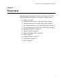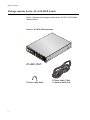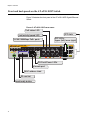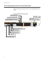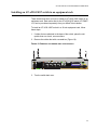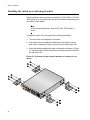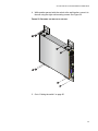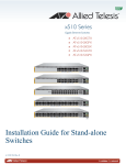
1
AT-x230-10GP AT-x230-18GP Gigabit Ethernet Switches x230-10GP 1 3 5 7 SFP 9 CONSOLE MAC Address Label SD FAULT SD 10 POWER 2 RS-232 1000 LINK MAC Address Label Installation Guide C613-04068-00 REV A ACT 10/100 LINK 4 ACT 6 8 PD ON PD ERR MAX CURRENT Copyright 2014 Allied Telesis, Inc. All rights reserved. No part of this publication may be reproduced without prior written permission from Allied Telesis, Inc. Allied Telesis and the Allied Telesis logo are trademarks of Allied Telesis, Incorporated. All other product names, company names, logos or other designations mentioned herein are trademarks or registered trademarks of their respective owners. Allied Telesis, Inc. reserves the right to make changes in specifications and other information contained in this document without prior written notice. The information provided herein is subject to change without notice. In no event shall Allied Telesis, Inc. be liable for any incidental, special, indirect, or consequential damages whatsoever, including but not limited to lost profits, arising out of or related to this manual or the information contained herein, even if Allied Telesis, Inc. has been advised of, known, or should have known, the possibility of such damages. Electrical Safety and Emissions Standards This product meets the following standards. U.S. Federal Communications Commission Radiated Energy Note: This equipment has been tested and found to comply with the limits for a Class A digital device pursuant to Part 15 of FCC Rules. These limits are designed to provide reasonable protection against harmful interference when the equipment is operated in a commercial environment. This equipment generates, uses, and can radiate radio frequency energy and, if not installed and used in accordance with this instruction manual, may cause harmful interference to radio communications. Operation of this equipment in a residential area is likely to cause harmful interference in which case the user will be required to correct the interference at his own expense. Note: Modifications or changes not expressly approved of by the manufacturer or the FCC, can void your right to operate this equipment. Industry Canada This Class A digital apparatus meets all requirements of the Canadian Interference-Causing Equipment Regulations. Cet appareil numérique de la classe A respecte toutes les exigences du Règlement sur le matériel brouilleur du Canada. EMC EN 55022 Class A EN 55024 EN 61000-3-2 EN 61000-3-3 EN 62311 FCC Part 15 (CFR 47) Class A VCCI Class A CISPR 22 Class A ICES-003 Warning: In a domestic environment this product may cause radio interference in which case the user may be required to take adequate measures. Environmental Compliance RoHS WEEE Electrical Safety EN 60950-1 (edition 2) IEC 60950-1 (edition 2) UL 60950-1 (edition 2) Laser Safety EN 60825 Regulatory Compliance RCM CE C-UL-US UL-EU i Translated Safety Statements Important: The indicates that a translation of the safety statement is available in a PDF document titled Translated Safety Statements posted on the Allied Telesis website at www.alliedtelesis.com. ii AT-x230-10GP and AT-x230-18GP Switches Installation Guide Contents Preface............................................................................................................................................................... 1 Symbol conventions ..................................................................................................................................... 2 Contacting Allied Telesis.............................................................................................................................. 3 Chapter 1: Overview..........................................................................................................................................5 Features ....................................................................................................................................................... 6 Twisted pair ports .................................................................................................................................. 6 SFP slots ............................................................................................................................................... 6 LEDs...................................................................................................................................................... 7 Installation options................................................................................................................................. 7 Power conservation ............................................................................................................................... 7 MAC address table ................................................................................................................................ 7 Package contents for the AT-x230-10GP Switch......................................................................................... 8 Package contents for the AT-x230-18GP Switch......................................................................................... 9 Front and back panels on the AT-x230-10GP Switch ................................................................................ 10 Front and back panels on the AT-x230-18GP Switch ................................................................................ 12 Management software................................................................................................................................ 14 Twisted pair ports....................................................................................................................................... 15 Power over Ethernet (PoE) ........................................................................................................................ 16 PoE standards ..................................................................................................................................... 16 Powered device classes ...................................................................................................................... 16 Cable requirements ............................................................................................................................. 17 Power budget ...................................................................................................................................... 19 Port prioritization.................................................................................................................................. 20 Wiring implementation ......................................................................................................................... 21 LEDs .......................................................................................................................................................... 22 POWER and FAULT LEDs.................................................................................................................. 22 10/1000BASE-T/100BASE-TX Link/Activity/Speed LED and PoE status LED ................................... 24 SFP LEDs............................................................................................................................................ 27 SD card LED........................................................................................................................................ 28 ecofriendly button....................................................................................................................................... 30 Power supply.............................................................................................................................................. 31 Fans ........................................................................................................................................................... 32 Chapter 2: Installation.................................................................................................................................... 33 Reviewing safety precautions .................................................................................................................... 34 Selecting a site for the switch..................................................................................................................... 36 Cable specifications ................................................................................................................................... 37 Unpacking the switch: AT-x230-10GP ....................................................................................................... 38 Unpacking the switch: AT-x230-18GP ....................................................................................................... 39 Installing the switch on a table or a desktop .............................................................................................. 40 Installing an AT-x230-10GP switch in an equipment rack.......................................................................... 42 Installing an AT-x230-18GP switch in an equipment rack.......................................................................... 45 Installing the switch on a wall using brackets............................................................................................. 48 Cabling the switch ...................................................................................................................................... 50 Powering on the switch .............................................................................................................................. 52 Starting a local management session ........................................................................................................ 54 Monitoring the initialization processes ....................................................................................................... 56 Installing optional SFP transceivers ........................................................................................................... 59 iii Contents Chapter 3: Troubleshooting........................................................................................................................... 63 Appendix A: Technical Specifications.......................................................................................................... 67 Physical specifications................................................................................................................................ 67 Dimensions .......................................................................................................................................... 67 Weight .................................................................................................................................................. 67 Environmental specifications ...................................................................................................................... 67 Power specifications................................................................................................................................... 68 Electrical safety and electromagnetic certifications .................................................................................... 68 Connectors and port pinouts ...................................................................................................................... 69 iv Figures Figure 1: AT-x230-10GP packaging ...................................................................................................................................... 8 Figure 2: AT-x230-18GP packaging ...................................................................................................................................... 9 Figure 3: AT-x230-10GP front panel.................................................................................................................................... 10 Figure 4: AT-x230-10GP back panel ................................................................................................................................... 11 Figure 5: AT-x230-18GP front panel.................................................................................................................................... 12 Figure 6: AT-x230-18GP back panel ................................................................................................................................... 13 Figure 7: POWER LED on an x230 Series Switch .............................................................................................................. 22 Figure 8: FAULT LED on an x230 Series Switch................................................................................................................. 23 Figure 9: AT-x230-10GP Link/Activity/Speed and PoE LEDs.............................................................................................. 25 Figure 10: AT-x230-18GP Link/Activity/Speed and PoE LEDs............................................................................................ 25 Figure 11: SFP Link/Activity LEDs on an x230 Series Switch ............................................................................................. 27 Figure 12: SD card slot LED on an x230 Series Switch ...................................................................................................... 28 Figure 13: ecofriendly button on an x230 Series Switch...................................................................................................... 30 Figure 14: Attaching the rubber feet to a switch .................................................................................................................. 41 Figure 15: Removing the rubber feet from a switch............................................................................................................. 42 Figure 16: Attaching rack mount brackets to an AT-x230-10GP ......................................................................................... 43 Figure 17: Mounting an AT-x230-10GP switch in an equipment rack ................................................................................. 44 Figure 18: Removing the rubber feet from a switch............................................................................................................. 45 Figure 19: Attaching rack mount brackets to the AT-x230-18GP switch............................................................................. 46 Figure 20: Mounting an AT-x230-18GP switch in an equipment rack ................................................................................. 47 Figure 21: Attaching the wall mount brackets to the side of the switch ............................................................................... 48 Figure 22: Securing the switch to the wall .......................................................................................................................... 49 Figure 23: Lifting the AC power cable hook on an x230 Series Switch ............................................................................... 52 Figure 24: Plugging in the AC power cord on an x230 Series Switch ................................................................................. 52 Figure 25: Connecting the management cable to the console port of an x230 Series Switch............................................. 54 Figure 26: Switch initialization messages ............................................................................................................................ 56 Figure 27: Switch initialization messages (continued) ......................................................................................................... 57 Figure 28: Switch initialization messages (continued) ........................................................................................................ 58 Figure 29: Removing the dust plug from an SFP slot .......................................................................................................... 59 Figure 30: Inserting an SFP transceiver into an SFP slot.................................................................................................... 60 Figure 31: Positioning the SFP handle in the upright position ............................................................................................ 60 Figure 32: Ejecting an SFP transceiver after lowering the SFP handle to the downwards position .................................... 61 Figure 33: RJ45 connector and port pin layout.................................................................................................................... 69 v List of Figures vi Tables Table 1. IEEE powered device classes ..............................................................................................................................17 Table 2. Twisted pair cable requirements for the 10BASE-T and 100BASE-TX ports at 10 or 100Mbps ..........................18 Table 3. Twisted pair cable requirements for the 10/1000BASE-T and 100BASE-TX ports at 1000Mbps ........................19 Table 4. AT-x230-10GP and AT-x230-18GP POWER LED functional descriptions ..........................................................23 Table 5. AT-x230-10GP and AT-x230-18GP FAULT LED functional descriptions ............................................................24 Table 6. AT-x230-10GP and AT-x230-18GP Link/Activity/Speed and PoE LED descriptions ...........................................26 Table 7. SFP Link/Activity LED functional descriptions ......................................................................................................28 Table 8. SD card LED functional descriptions ....................................................................................................................29 Table 9. Twisted pair cabling and distances ......................................................................................................................37 Table 10. Chassis dimensions ............................................................................................................................................67 Table 11. Chassis weight ...................................................................................................................................................67 Table 12. Environmental specifications ..............................................................................................................................67 Table 13. Chassis weight ...................................................................................................................................................68 Table 14. Safety and electromagnetic emissions certifications ..........................................................................................68 Table 15. MDI pin signals (10BASE-T or 100BASE-TX) ....................................................................................................69 Table 16. MDIX pin signals (10BASE-T or 100BASE-TX) ..................................................................................................69 Table 17. RJ-45 1000BASE-T connector pinouts ...............................................................................................................70 vii List of Tables viii AT-x230-10GP and AT-x230-18GP Switches Installation Guide Preface This guide contains the installation instructions for the AT-x230-10GP and AT-x230-18GP Gigabit Ethernet Switches. This preface contains the following sections: “Symbol conventions” on page 2 “Contacting Allied Telesis” on page 3 1 Symbol conventions This document uses the following conventions: Note Notes provide additional information. Caution Cautions inform you that performing or omitting a specific action may result in equipment damage or loss of data. Warning Warnings inform you that performing or omitting a specific action may result in bodily injury. Warning Warnings inform you that an eye and skin hazard exists due to the presence of a Class 1 laser device. 2 AT-x230-10GP and AT-x230-18GP Switches Installation Guide Contacting Allied Telesis If you need assistance with this product, you may contact Allied Telesis technical support by going to the Support & Services section of the Allied Telesis web site at www.alliedtelesis.com/support. You can find links for the following services on this page: 24/7 Online Support - Enter our interactive support center to search for answers to your questions in our knowledge database, check support tickets, learn about RMAs, and contact Allied Telesis technical experts. USA and EMEA phone support - Select the phone number that best fits your location and customer type. Hardware warranty information - Learn about Allied Telesis warranties and register your product online. Replacement Services - Submit a Return Merchandise Authorization (RMA) request via our interactive support center. Documentation - View the most recent installation guides, user guides, software release notes, white papers and data sheets for your product. Software Updates - Download the latest software releases for your product. For sales or corporate contact information, go to www.alliedtelesis.com/purchase and select your region. 3 4 AT-x230-10GP and AT-x230-18GP Switches Installation Guide Chapter 1 Overview This chapter provides descriptions of the AT-x230-10GP and AT-x23018GP Gigabit Ethernet Switches and contains the following sections: “Features” on page 6 “Package contents for the AT-x230-10GP Switch” on page 8 “Package contents for the AT-x230-18GP Switch” on page 9 “Front and back panels on the AT-x230-10GP Switch” on page 10 “Front and back panels on the AT-x230-18GP Switch” on page 12 “Management software” on page 14 “Twisted pair ports” on page 15 “Power over Ethernet (PoE)” on page 16 “LEDs” on page 22 “ecofriendly button” on page 30 “Power supply” on page 31 “Fans” on page 32 5 Chapter 1: Overview Features This section describes the hardware features of the AT-x230-10GP and AT-x230-18GP Gigabit Ethernet Switches. Twisted pair ports SFP slots Here are the basic features of the 10/100/1000Mbps twisted-pair ports: 8 or 16 PoE ports per switch 10BASE-T (IEEE 802.3i), 100BASE-TX (IEEE 802.3u) and 1000BASE-T (IEEE 802.3ab) compliant IEEE 802.3u Auto-Negotiation compliant Auto-MDI/MDIX PoE Plus Full wire-speed non-blocking IEEE 802.3x Flow Control in 10BASE-T/100BASE-TX full-duplex operation IEEE 802.3x Back Pressure in 10BASE-T/100BASE-TX halfduplex operation IEEE803.3z 1000BASE-T Flow Control Support for jumbo packets up to 10KB One RJ45 connector on front panel for RS232 console purposes. Each switch has two SFP ports on the front panel. The ports are available for 100Mbps or 1000Mbps of fiber, and 1000Mbps of copper, and support 100BASE-FX and 1000BASE-SX/LX transceivers. You need to purchase SFP transceivers separately. For a list of supported transceivers, contact your Allied Telesis distributor or reseller. Note See the product data sheets for the specific ATI SFP modules supported by the x230 Series Switches. 6 AT-x230-10GP and AT-x230-18GP Switches Installation Guide LEDs Here is a brief description of the port LEDs: POWER and FAULT LEDs; refer to “POWER and FAULT LEDs” on page 22. Link/Activity/Speed/PoE LEDs for the twisted pair ports; see “10/ 1000BASE-T/100BASE-TX Link/Activity/Speed LED and PoE status LED” on page 24. Link/Activity LEDs for the SFP slots; see “SFP LEDs” on page 27. SD card LED: refer to “SD card LED” on page 28. Note The ecofriendly button turns off the LEDs (excluding the POWER LED) to conserve electricity. See “ecofriendly button” on page 30. Installation options Power conservation MAC address table The AT-x230-10GP and AT-x230-18GP switches can be installed in the following ways: Rack mounted in a 19-inch equipment rack Mounted on a desk or tabletop Wall mounted The AT-x230-10GP and AT-x230-18GP switches implement Eco-Switch Green Power saving features and use less power than the METI specification. The switches have the following power conservation features: ecofriendly button to turn off the port LEDs when the system is not being monitored High efficiency power supply Power scaling based on traffic loads on ports operating at 1000Mbps (port power scaling not available at 10 or 100Mbps) Power shutdown on unused ports Here are the basic features of the MAC address table: Storage capacity up to 16KB MAC address entries Automatic learning and aging 7 Chapter 1: Overview Package contents for the AT-x230-10GP Switch Figure 1 illustrates the package contents for the AT-x230-10GP Gigabit Ethernet Switch. FIGURE 1. AT-X230-10GP PACKAGING x2 30 -10 GP MA CA dd ress SD Lab el CO NSO LE 1 RS23 3 SD FA 2 ULT PO WER 1000 5 7 LINK AC T 10/1 2 00 LINK SF 4 AC T P 6 9 PD 8 ON PD ER R MAX CU 10 RR EN T AT-x230-10GP 1 Power cable hook 8 1 Power cable (1.8m) 1 Console cable (2m) AT-x230-10GP and AT-x230-18GP Switches Installation Guide Package contents for the AT-x230-18GP Switch Figure 2 illustrates the package contents for the AT-x230-18GP Gigabit Ethernet Switch. FIGURE 2. AT-X230-18GP PACKAGING AT-x230-18GP 1 Power cable hook 1 Power cable (1.8m) 1 Console cable (2m) 9 Chapter 1: Overview Front and back panels on the AT-x230-10GP Switch Figure 3 illustrates the front panel of the AT-x230-10GP Gigabit Ethernet Switch. FIGURE 3. AT-X230-10GP FRONT PANEL PoE status LED SFP slots Link/activity/speed LED SFP LEDs: Upper (left), lower (right) 10/100/1000Mbps PoE+ ports x230-10GP 1 3 5 7 SFP 9 CONSOLE MAC Address Label SD FAULT SD 10 POWER 2 RS-232 1000 LINK ACT 10/100 LINK 4 ACT 6 8 PD ON SD/Fault/Power LEDs Console port MAC address label SD card slot ecofriendly button 10 PD ERR MAX CURRENT AT-x230-10GP and AT-x230-18GP Switches Installation Guide Figure 4 illustrates the back panel of the AT-x230-10GP Gigabit Ethernet Switch. FIGURE 4. AT-X230-10GP BACK PANEL Power connector Power cable hook Power cable hook mount 11 Chapter 1: Overview Front and back panels on the AT-x230-18GP Switch Figure 5 illustrates the front panel of the AT-x230-18GPGigabit Ethernet Switch. FIGURE 5. AT-X230-18GP FRONT PANEL PoE status LED SFP slots Link/activity/speed LED 10/100/1000Mbps PoE+ ports MAC Address Label SD/Fault/Power LEDs Console port MAC address label SD card slot ecofriendly button 12 SFP LEDs: Upper (left), lower (right) AT-x230-10GP and AT-x230-18GP Switches Installation Guide Figure 6 illustrates the back panel of the AT-x230-18GP Gigabit Ethernet Switch. FIGURE 6. AT-X230-18GP BACK PANEL Power connector Power cable hook Power cable hook mount 13 Chapter 1: Overview Management software The switches are shipped with the management software pre-installed. The software provides a command line interface and a GUI (Graphical User Interface) for in-band, over-the-network management. Refer to the: AlliedWare Plus Software Reference for x230 Series Switches In the unlikely event that the management software becomes corrupted or damaged on the switch, you can download the software from the Allied Telesis corporate web site and reinstall it on the switch. For instructions on how to install new management software, see the product documentation. 14 AT-x230-10GP and AT-x230-18GP Switches Installation Guide Twisted pair ports The AT-x230-10GP and AT-x230-18GP Gigabit Ethernet Switches feature 8 and 16 twisted pair ports, respectively. All ports are 10BASE-T, 100BASE-TX, and 1000BASE-T compliant. You can set the port speeds and duplex modes either automatically with IEEE 802.3u Auto-Negotiation or manually with the management software. The twisted pair ports feature 8-pin RJ45 connectors. For the port pinouts, see “Connectors and port pinouts” on page 69. The ports have a maximum operating distance of 100 m (328 feet). For 10 Mbps operation, the ports require Category 3 or better 100 ohm shielded or unshielded twisted pair cabling. For 100 or 1000Mbps operation, the ports require Category 5 or Enhanced Category 5 (5E) 100 ohm shielded or unshielded twisted pair cabling. The ports feature auto-MDI, which automatically configures the ports as MDI or MDIX. This feature allows you to use straight-through twisted pair cables regardless of the wiring configurations of the ports on the end nodes. Note A switch port connected to an end node that is not using AutoNegotiation should not use Auto-Negotiation to set the speed and duplex mode, as a duplex mode mismatch may occur. In this case, disable Auto-Negotiation and set the port’s speed and duplex mode manually. 15 Chapter 1: Overview Power over Ethernet (PoE) The AT-x230-10GP and AT-x230-18GP switches feature Power over Ethernet (PoE) on the 10/1000BASE-T and 100BASE-TX ports. PoE is used to supply power to network devices over the same twisted pair cables that carry the network traffic. The main advantage of PoE is that it can make it easier to install a network. The selection of a location for a network device is often limited by whether there is a power source nearby. This often limits equipment placement or requires the added time and cost of having additional electrical sources installed. But with PoE, you can install PoE-compatible devices wherever they are needed without having to worry about whether there are power sources nearby. A device that provides PoE to other network devices is referred to as power sourcing equipment (PSE). Both the AT-x230-10GP and AT-x23018GP switches act as PSE units by adding DC power to the network cable, thus functioning as a central power source for other network devices. Devices that receive their power from PSE are called powered devices (PD). Examples of PD include wireless access points, IP telephones, webcams, and even other Ethernet switches. The switch automatically determines if a device connected to a port is a powered device. Ports that are connected to network nodes that are not powered devices (that is, devices that receive their power from another power source) function as regular Ethernet ports, without PoE. The PoE feature remains activated on the ports but no power is delivered to the devices. PoE standards Powered device classes 16 The AT-x230-10GP and AT-x230-18GP switches support these PoE standards: PoE (IEEE 802.3af): This standard provides up to 15.4 watts at the switch port to support powered devices that require up to 12.95 watts. PoE+ (IEEE 802.3at): This standard provides up to 30.0 watts at the switch port to support powered devices that require up to 25.5 watts. Powered devices are grouped into the five classes listed in Table 1 on page 17. The classes are based on the amount of power the devices require. Both the AT-x230-10GP and AT-x230-18GP switches support all five classes. AT-x230-10GP and AT-x230-18GP Switches Installation Guide TABLE 1. IEEE POWERED DEVICE CLASSES Class Maximum power output from a switch port PD power range Margin of cable loss 0 16.2W 0.44W to 12.95W 0.8W 1 4.2W 0.44W to 3.84W 0.2W 2 7.4W 3.84W to 6.49W 0.4W 3 16.2W 6.49W to 12.95W 0.8W 4 31.2W 12.95W to 25.5W 1.2W Cable requirements The cable requirements for ports operating at 10 or 100Mbps are given in Table 2. The cable requirements for ports operating at 1000Mbps are given in Table 3. 17 Chapter 1: Overview TABLE 2. TWISTED PAIR CABLE REQUIREMENTS FOR THE 10BASE-T AND 100BASE-TX PORTS AT 10 OR 100MBPS 10Mbps Cable type 100Mbps Non PoE PoE PoE+ Non PoE PoE PoE+ Cat 3: Standard TIA/EIA 568-Bcompliant Category 3 shielded or unshielded cabling with 100 ohm impedance and a frequency of 16 MHz Yes Yes No Yes Yes No Cat 5: Standard TIA/EIA 568-Acompliant Category 5 shielded or unshielded cabling with 100 ohm impedance and a frequency of 100 MHz Yes Yes No Yes Yes No Cat 5e: Standard TIA/EIA 568B-compliant Enhanced Category 5 (Cat 5e) shielded or unshielded cabling with 100 ohm impedance and a frequency of 100 MHz Yes Yes Yes Yes Yes Yes Cat 6 or 6a: Standard TIA/EIA 568-B-compliant Category 6 or 6a shielded cabling Yes Yes Yes Yes Yes Yes 18 AT-x230-10GP and AT-x230-18GP Switches Installation Guide TABLE 3. TWISTED PAIR CABLE REQUIREMENTS FOR THE 10/1000BASE-T AND 100BASE-TX PORTS AT 1000MBPS 1000Mbps Cable type Power budget Non-PoE PoE PoE+ Cat 3: Standard TIA/EIA 568-Bcompliant Category 3 shielded or unshielded cabling with 100 ohm impedance and a frequency of 16 MHz No No No Cat 5: Standard TIA/EIA 568-Acompliant Category 5 shielded or unshielded cabling with 100 ohm impedance and a frequency of 100 MHz Yes Yes No Cat 5e: Standard TIA/EIA 568B-compliant Enhanced Category 5 (Cat 5e) shielded or unshielded cabling with 100 ohm impedance and a frequency of 100 MHz Yes Yes Yes Cat 6 or 6a: Standard TIA/EIA 568-B-compliant Category 6 or 6a shielded cabling Yes Yes Yes The AT-x230-10GP and AT-x230-18GP switches each have a power budget of 124 and 247 watts, respectively. This is the maximum amount of power the switches can provide at one time to the powered devices. The power requirements of the PoE devices determine the maximum number of devices the switch can support at one time. So long as the total power requirements of the powered devices is less than the power budget of the switch, the switch can supply power to all the devices. But if the total power requirements exceed the power budget, the switch denies power to one or more ports using a mechanism referred to as port prioritization. To determine whether the power requirements of the PoE devices you plan to connect to the switch exceed its power budget, refer to their documentation for their power requirements and add the requirements together. The switch should be able to power all of the devices simultaneously as long as the total is below its power budget. If the total exceeds the available power budget, you should consider reducing the 19 Chapter 1: Overview number of PoE devices so that all of the devices receive power. Otherwise, the switch powers a subset of the devices, based on port prioritization. The switch can handle different power requirements on different ports. This enables you to connect different classes of PoE equipment to the ports on the switch. Port prioritization If the power requirements of the powered devices exceed the switch’s power budget, the switch denies power to some ports based on a system called port prioritization. You may use this mechanism to ensure that powered devices critical to the operations of your network are given preferential treatment by the switch in the distribution of power should the demands of the devices exceed the available capacity. There are three priority levels: Critical High Low Ports set to the Critical level, the highest priority level, are guaranteed power before any of the ports assigned to the other two priority levels. Ports assigned to the other priority levels receive power only if all the Critical ports are receiving power. Ports that are connected to your most critical powered devices should be assigned to this level. If there is not enough power to support all the ports set to the Critical priority level, power is provided to the ports based on port number, in ascending order. The High level is the second highest level. Ports set to this level receive power only if all the ports set to the Critical level are already receiving power. If there is not enough power to support all of the ports set to the High priority level, power is provided to the ports based on port number, in ascending order. The lowest priority level is Low. This is the default setting. Ports set to this level only receive power if all of the ports assigned to the other two levels are already receiving power. As with the other levels, if there is not enough power to support all of the ports set to the Low priority level, power is provided to the ports based on port number, in ascending order. Power allocation is dynamic. Ports supplying power to powered devices may cease power transmission if the switch’s power budget is at maximum usage and new powered devices, connected to ports with higher priorities, become active. 20 AT-x230-10GP and AT-x230-18GP Switches Installation Guide Wiring implementation The IEEE 802.3af standard defines two methods for the delivery of DC power over twisted pair cable by a PSE, such as the switch, to PDs. These methods, known as modes A and B, identify the wires within the cable that carry the DC power from the PSE to a PD. Twisted pair cabling typically consists of eight wires. With 10BASE-T and 100BASE-TX devices, the wires connected to pins 1, 2, 3, and 6 on the RJ- 45 connectors carry the network traffic while the wires connected to pins 4, 5, 7, and 8 are unused. With 1000BASE-T devices, all eight wires are used to carry network data. It takes four wires to deliver DC power to a PD. With Mode A, the power is delivered on pins 1, 2, 3, and 6. These are the same pins in 10BASE-T and 100BASE-TX devices that carry the network data. With mode B, the power is provided over the spare wires. The ports on the AT-x230-10GP and AT-x230-18GP switches deliver the power using pins 1, 2, 3, and 6, which corresponds to mode A in the IEEE 802.3af standard. Powered devices that comply with the IEEE 802.3af standard are required to support both power delivery methods. Legacy devices that do not comply with the standard will work with the switch if they are powered on pins 1, 2, 3, and 6. 21 Chapter 1: Overview LEDs This section describes the four types of LEDs on the x230 Series Switches: POWER and FAULT LEDs “POWER and FAULT LEDs” on page 22 “10/1000BASE-T/100BASE-TX Link/Activity/Speed LED and PoE status LED” on page 24 “SFP LEDs” on page 27 “SD card LED” on page 28 The POWER LED reports the status of AC power and is located on the front panel of the of the switches beside the console port. See Figure 7. Note All port LEDs are OFF when the switch is operating in the low power mode. To toggle on the LEDs, use the ecofriendly button. See “ecofriendly button” on page 30 for more information. FIGURE 7. POWER LED ON AN X230 SERIES SWITCH 10GP 1 CONSOLE ess Label POWER LED Power LED SD FAULT D POWER 2 RS-232 1000 LINK 22 ACT 10/100 LINK ACT AT-x230-10GP and AT-x230-18GP Switches Installation Guide Table 4 describes the POWER LED for the AT-x230-10GP and AT-x23018GP switches. TABLE 4. AT-X230-10GP AND AT-X230-18GP POWER LED FUNCTIONAL DESCRIPTIONS LED Description State Off Indicates either the switch is not receiving AC power or the AC input power is operating outside the normal range Steady green The switch is receiving AC input power and is operating normally POWER Figure 8 shows the location of the FAULT LED. FIGURE 8. FAULT LED ON AN X230 SERIES SWITCH 10GP 1 CONSOLE Fault LED ess Label SD FAULT D POWER 2 RS-232 1000 LINK ACT 10/100 LINK ACT 23 Chapter 1: Overview Table 5 describes the functions of the FAULT LED for the AT-x230-10GP and AT-x230-18GP switches. TABLE 5. AT-X230-10GP AND AT-X230-18GP FAULT LED FUNCTIONAL DESCRIPTIONS LED State Off FAULT Red flashing once Red flashing six times 10/1000BASE-T/ 100BASE-TX Link/Activity/ Speed LED and PoE status LED Description The switch is receiving AC input power and is operating normally Indicates fan failure Indicates the switch’s temperature has exceeded the threshold The Link/Activity/Speed and PoE LEDs provide information about the 10/ 1000BASE-T and the 100BASE-TX ports. The AT-x230-10GP and AT-x230-18GP switches indicate Link/Activity/ Speed and PoE status with two LEDs for each port (Figure 9 and Figure 10). For each port: the left LED corresponds to Link/Activity/Speed the right LED corresponds to PoE status Note All of the port LEDs are OFF when the switch is operating in the low power mode. To toggle on the LEDs, use the ecofriendly button. See “ecofriendly button” on page 30 for more information. 24 AT-x230-10GP and AT-x230-18GP Switches Installation Guide FIGURE 9. AT-X230-10GP LINK/ACTIVITY/SPEED AND POE LEDS PoE status LED Link/activity/speed LED 10/100/1000Mbps PoE+ ports 1 3 5 7 LT WER 2 ACT 10/100 LINK 4 ACT 6 8 PD ON PD ERR MAX C FIGURE 10. AT-X230-18GP LINK/ACTIVITY/SPEED AND POE LEDS PoE status LED Link/activity/speed LED 10/100/1000Mbps PoE+ ports 25 Chapter 1: Overview Table 6 describes the AT-x230-10GP and AT-x230-18GP Link/Activity/ Speed and PoE status LEDs. TABLE 6. AT-X230-10GP AND AT-X230-18GP LINK/ACTIVITY/SPEED AND POE LED DESCRIPTIONS LED Link/Activity/ Speed (LEFT LED) State Description Off The port has not established a link with a network device, or the ecofriendly feature is enabled. Flashing green Steady green Flashing amber Steady amber Off PoE Steady green (RIGHT LED) Flashing amber Steady amber 26 Rx or Tx activities at 1000M The port has established a link with a network device and is active (1000M) Rx or Tx activities at 10/100M The port has established a link with a network device and is active (10/100M) No link, no power output, or ecofriendly feature is enabled PD is on PD maximum current PD error AT-x230-10GP and AT-x230-18GP Switches Installation Guide SFP LEDs The AT-x230-10GP and AT-x230-18GP switches have SFP Link/Activity LEDs on the front panel. See Figure 11. The SFP Link/Activity LEDs indicate the activity status for each SFP slot. Each SFP slot has ONE uni-color LED: The LEFT LED corresponds to the UPPER SFP port The RIGHT LED corresponds to the LOWER SFP port Note All of the port LEDs are OFF when the switch is operating in the low power mode. To toggle on the LEDs, use the ecofriendly button. See “ecofriendly button” on page 30 for more information. FIGURE 11. SFP LINK/ACTIVITY LEDS ON AN X230 SERIES SWITCH Upper (left) SFP LED Lower (right) SFP LED SFP 9 SFP slots 10 MAX CURRENT 27 Chapter 1: Overview Table 7 describes the functions of the SFP Link/Activity LEDs TABLE 7. SFP LINK/ACTIVITY LED FUNCTIONAL DESCRIPTIONS LED State The port on the SFP transceiver has not established a link with an end node, OR the ecofriendly feature is enabled Off SFP Flashing green Steady green SD card LED Description Rx or Tx activities The SFP transceiver has established a link with a network device The AT-x230-10GP and AT-x230-18GP switches have an SD card LED on the front panel (see Figure 12) Note All of the port LEDs are OFF when the switch is operating in the low power mode. To toggle on the LEDs, use the ecofriendly button. See “ecofriendly button” on page 30 for more information. FIGURE 12. SD CARD SLOT LED ON AN X230 SERIES SWITCH 10GP 1 CONSOLE SD card LED ess Label SD FAULT D POWER 2 RS-232 1000 LINK 28 ACT 10/100 LINK ACT AT-x230-10GP and AT-x230-18GP Switches Installation Guide The SD card LED indicates whether the SD card slot has a card inserted, or is reading or writing. Table 8 describes the functions of the SD card LED. TABLE 8. SD CARD LED FUNCTIONAL DESCRIPTIONS LED State Off SD card Description SD card is not inserted OR the ecofriendly feature is enabled Flashing green Writing or reading Steady green SD card is inserted Flashing amber Writing or reading error 29 Chapter 1: Overview ecofriendly button By pressing the ecofriendly button you can conserve energy. When you press the ecofriendly button for 1 to 4 seconds, the front panel port LEDs are disabled. You may use the button to turn off the LEDs when you are not monitoring the switch. To turn the port LEDs on, press the ecofriendly button for 1 to 4 seconds again. Toggling the LEDs does not affect the network operations of the switch. FIGURE 13. ECOFRIENDLY BUTTON ON AN X230 SERIES SWITCH x230-10G MAC Address Lab SD ecofriendly button Note The ecofriendly button does not control the POWER LED. 30 AT-x230-10GP and AT-x230-18GP Switches Installation Guide Power supply Each switch has an internal power supply with a single AC power supply socket on the back panel. To power the switch on or off, connect or disconnect the power cord provided with the switch. A power cord and a power cord retainer hook are supplied with the switch. For the power requirements, see “Power specifications” on page 68. 31 Chapter 1: Overview Fans Both the AT-x230-10GP and AT-x230-18GP switches have one and two internal fans respectively. You cannot remove or replace these fans in the field. The fan status is indicated with the FAULT LED. See “POWER and FAULT LEDs” on page 22 and Table 5 on page 24 for more information. 32 AT-x230-10GP and AT-x230-18GP Switches Installation Guide Chapter 2 Installation This chapter contains the following sections: “Reviewing safety precautions” on page 34 “Selecting a site for the switch” on page 36 “Cable specifications” on page 37 “Unpacking the switch: AT-x230-10GP” on page 38 “Unpacking the switch: AT-x230-18GP” on page 39 “Installing the switch on a table or a desktop” on page 40 “Installing an AT-x230-10GP switch in an equipment rack” on page 42 “Installing an AT-x230-18GP switch in an equipment rack” on page 45 “Installing the switch on a wall using brackets” on page 48 “Cabling the switch” on page 50 “Powering on the switch” on page 52 “Starting a local management session” on page 54 “Monitoring the initialization processes” on page 56 “Installing optional SFP transceivers” on page 59 33 Chapter 2: Installation Reviewing safety precautions Please review the following safety precautions before you begin to install the chassis or any of its components. Note The indicates that a translation of the safety statement is available in a PDF document titled Translated Safety Statements. Warning To prevent electric shock, do not remove the cover. No userserviceable parts inside. This unit contains hazardous voltages and should only be opened by a trained and qualified technician. To avoid the possibility of electric shock, disconnect electric power to the product before connecting or disconnecting the cables. E1 Warning Do not work on equipment or cables during periods of lightning activity. E2 Warning Power cord is used as a disconnection device. To de-energize equipment, disconnect the power cord. E3 Warning Class I Equipment. This equipment must be earthed. The power plug must be connected to a properly wired earth ground socket outlet. An improperly wired socket outlet could place hazardous voltages on accessible metal parts. E4 Pluggable equipment: The socket outlet shall be installed near the equipment and shall be easily accessible. E5 Caution Air vents must not be blocked and must have free access to the room ambient air for cooling. E6 Operating temperature: This product is designed for a maximum ambient temperature of 50° degrees C. E7 34 AT-x230-10GP and AT-x230-18GP Switches Installation Guide All countries: Install product in accordance with local and National Electrical Codes. E8 Circuit overloading: Consideration should be given to the connection of the equipment to the supply circuit and the effect that overloading of circuits might have on overcurrent protection and supply wiring. Appropriate consideration of equipment nameplate ratings should be used when addressing this concern. E21 Warning Mounting of the equipment in the rack should be such that a hazardous condition is not created due to uneven mechanical loading. E25 If installed in a closed or multi-unit rack assembly, the operating ambient temperature of the rack environment may be greater than the room ambient temperature. Therefore, consideration should be given to installing the equipment in an environment compatible with the manufacturer’s maximum rated ambient temperature (Tmra). E35 Caution Installation of the equipment in a rack should be such that the amount of air flow required for safe operation of the equipment is not compromised. E36 Warning Reliable earthing of rack-mounted equipment should be maintained. Particular attention should be given to supply connections other than direct connections to the branch circuits (e.g., use of power strips). E37 Warning To reduce the risk of electric shock, the PoE ports on this product must not connect to cabling that is routed outside the building in which the device is located. E40 35 Chapter 2: Installation Selecting a site for the switch Observe the following requirements when choosing a site for your switch: 36 If you plan to install the switch in an equipment rack, verify that the rack is safely secured and will not tip over. Devices in a rack should be installed starting at the bottom, with the heavier devices near the bottom of the rack. If you are installing the switch on a table, verify that the table is level and secure. The power outlet for the switch should be located near the unit and should be easily accessible. The site should provide for easy access to the ports on the front of the switch. This will make it easier for you to connect and disconnect cables, as well as view the switch’s LEDs. Air flow around the unit and through its vents on the side and rear should not be restricted so that the switch can maintain adequate cooling. Do not place objects on top of the switch. Do not expose the switch to moisture or water. Ensure that the site is in a dust-free environment. You should use dedicated power circuits or power conditioners to supply reliable electrical power to the network devices. AT-x230-10GP and AT-x230-18GP Switches Installation Guide Cable specifications Table 9 contains the cable specifications for the twisted pair ports. TABLE 9. TWISTED PAIR CABLING AND DISTANCES Speed Type of cable Maximum operating distance 10 Mbps Standard TIA/EIA 568-B-compliant Category 3 or better shielded or unshielded cabling with 100 ohm impedance and a frequency of 16 MHz. 100 m (328 ft) 100 Mbps Standard TIA/EIA 568-A-compliant Category 5 or TIA/EIA 568-Bcompliant Enhanced Category 5 (Cat 5e) shielded or unshielded cabling with 100 ohm impedance and a frequency of 100 MHz. 100 m (328 ft) 1000 Mbps Standard TIA/EIA 568-A-compliant Category 5 or TIA/EIA 568-Bcompliant Enhanced Category 5 (Cat 5e) shielded or unshielded cabling with 100 ohm impedance and a frequency of 100 MHz. 100 m (328 ft) Note The twisted pair ports on the switch feature auto-MDI when operating at 10, 100, or 1000 Mbps. A port is configured as MDI or MDIX when it is connected to an end node. Consequently, you can use a straight-through twisted pair cable when connecting any type of network device to a port on the switch. 37 Chapter 2: Installation Unpacking the switch: AT-x230-10GP To unpack the switch, perform the following procedure: 1. Remove all of the components from the shipping package. Note Store the packaging material in a safe location. You must use the original shipping material if you need to return the unit to Allied Telesis. 2. Place the switch on a level, secure surface. 3. Verify that the shipping container includes the following items: x2 30 -10 MA CA dd ress SD GP Lab el CO NS OL E 1 3 SD RS -232 FA UL T PO WER 1000 5 7 LIN K AC T 10/102 0 LIN K SF 4 AC T P 6 9 PD 8 ON PD ER R MA X CU RR 10 EN T AT-x230-10GP 1 Power cable hook 38 1 Power cable (1.8m) 1 Console cable (2m) AT-x230-10GP and AT-x230-18GP Switches Installation Guide Unpacking the switch: AT-x230-18GP To unpack the switch, perform the following procedure: 1. Remove all of the components from the shipping package. Note Store the packaging material in a safe location. You must use the original shipping material if you need to return the unit to Allied Telesis. 2. Place the switch on a level, secure surface. 3. Verify that the shipping container includes the following items: AT-x230-18GP 1 Power cable hook 1 Power cable (1.8m) 1 Console cable (2m) 39 Chapter 2: Installation Installing the switch on a table or a desktop You can install AT-x230-10GP and AT-x230-18GP switches on a desktop, in a standard 19-inch equipment rack, or on a wall. To install an AT-x230-10GP switch in a rack, see “Installing an AT-x23010GP switch in an equipment rack” on page 42. To install an AT-x230-18GP switch in a rack, see “Installing an AT-x23018GP switch in an equipment rack” on page 45. To install an AT-x230-10GP or an AT-x230-18GP switch on a wall, see “Installing the switch on a wall using brackets” on page 48. Here are the guidelines to selecting a suitable site for desktop or table use: The table should be level and stable and the power outlets should be located near the switches and be easily accessible. The site should allow for easy access to the ports on the front of the switches, so that you can easily connect and disconnect cables, and view the port LEDs. The site should allow for adequate air flow around the units and through the cooling vents on the front and rear panels (the ventilation direction is from front to back, with the fan on the back panel drawing the air out of the unit). The site should not expose the switches to moisture or water and the site should be a dust-free environment. The site should include dedicated power circuits or power conditioners to supply reliable electrical power to the network devices. The rubber feet on the base of the switches should be left on for table or desktop installation. If your switch does not already have rubber feet fitted, fit these as follows: 1. Remove all equipment from the package and store the packaging material in a safe place. 2. Turn the switch over and place it on a table. 3. Remove the rubber feet from the packaging and screw them firmly onto the base of the switch, as shown on Figure 14 on page 41: 40 AT-x230-10GP and AT-x230-18GP Switches Installation Guide FIGURE 14. ATTACHING THE RUBBER FEET TO A SWITCH 1000 LINK RS-232 ACT 10/100 LINK 2 ACT PD ON 4 6 PD ERR MAX CURRENT 8 POWER SD 10 FAULT MAC Address Label SD CONSOLE 9 x230-10GP 1 3 5 7 SFP 4. Turn the switch over again and place it on a flat, secure surface (such as a desk or table) leaving ample space around the unit for ventilation. 5. Go to “Cabling the switch” on page 50. 41 Chapter 2: Installation Installing an AT-x230-10GP switch in an equipment rack These instructions show you how to install an AT-x230-10GP switch in an equipment rack. Rack mount kits for the AT-x230-10GP switch, ATRKMT-J14, can be purchased separately from your Allied Telesis dealer. To install an AT-x230-10GP switch in a 19-inch equipment rack, follow these steps: 1. If rubber feet are attached to the base of the switch, place the unit upside down on a level, secure surface. 2. Remove the rubber feet with a screwdriver (Figure 15). FIGURE 15. REMOVING THE RUBBER FEET FROM A SWITCH 1000 LINK RS-232 ACT 10/100 LINK 2 ACT PD ON 4 6 PD ERR MAX CURRENT 8 POWER SD 10 FAULT MAC Address Label SD CONSOLE 9 1 3 5 7 SFP 42 x230-10GP 3. Turn the switch back over. AT-x230-10GP and AT-x230-18GP Switches Installation Guide 4. Attach two rack mount brackets to the sides of the switch using the eight bracket screws that come with the rack mount kit AT-RKMT-J14 (Figure 16). FIGURE 16. ATTACHING RACK MOUNT BRACKETS TO AN AT-X230-10GP x2 30 -10 GP MA CA dd re ss SD Lab el CO NS OL E 1 3 SD RS -232 FA ULT 5 PO WE R 1000 7 LIN K AC T 10/1 2 00 LIN K AC SF P 4 T 6 9 PD 8 ON PD ER R MAX CU 10 RR EN T 43 Chapter 2: Installation 5. Mount the AT-x230-10GP switch in a 19-inch equipment rack using four equipment rack screws (supplied with the equipment rack) (Figure 17). FIGURE 17. MOUNTING AN AT-X230-10GP SWITCH IN AN EQUIPMENT RACK x2 30 -10 GP MA CA dd re ss SD Lab el CO NSO LE 1 3 SD RS- 23 2 FA ULT PO WER 1000 5 7 LINK AC T 10/1 2 00 LINK AC SFP 4 T 6 9 PD 8 ON PD ER R MAX CU 10 RR EN T 6. Go to “Cabling the switch” on page 50 44 AT-x230-10GP and AT-x230-18GP Switches Installation Guide Installing an AT-x230-18GP switch in an equipment rack These instructions show you how to install an AT-x230-18GP switch in an equipment rack. Rack mount kits for the AT-x230-18GP switch, AT-RKMTJ13, can be purchased separately from your Allied Telesis dealer. To install an AT-x230-18GP switch in a 19-inch equipment rack, follow these steps: 1. If rubber feet are attached to the base of the switch, place the unit upside down on a level, secure surface. 2. Remove the rubber feet with a screwdriver (Figure 18). FIGURE 18. REMOVING THE RUBBER FEET FROM A SWITCH 1000 LINK RS-232 ACT 10/100 LINK 2 ACT PD ON 4 6 PD ERR MAX CURRENT 8 POWER SD 10 FAULT MAC Address Label SD CONSOLE 9 x230-10GP 1 3 5 7 SFP 3. Turn the switch back over. 45 Chapter 2: Installation 4. Attach two rack mount brackets to the sides of the switch using the six bracket screws that come with the rack mount kit AT-RKMT-J13 (Figure 19). FIGURE 19. ATTACHING RACK MOUNT BRACKETS TO THE AT-X230-18GP SWITCH 46 AT-x230-10GP and AT-x230-18GP Switches Installation Guide 5. Mount the AT-x230-18GP switch in a 19-inch equipment rack using four equipment rack screws (supplied with the equipment rack) (Figure 20). FIGURE 20. MOUNTING AN AT-X230-18GP SWITCH IN AN EQUIPMENT RACK 6. Go to “Cabling the switch” on page 50 47 Chapter 2: Installation Installing the switch on a wall using brackets These instructions show you how to install an AT-x230-10GP or AT-x23018GP switch on a wall. Wall mount kits can be purchased separately from your Allied Telesis dealer. Note In the following illustrations, only the AT-x230-10GP switch is shown. To install the switch on a wall, perform the following procedure: 1. Turn the switch over and place it on a table. 2. If the rubber feet are attached to the bottom of the switch, remove them with a screwdriver (Figure 18), then turn the switch back over. 3. Orient the brackets against the sides of the switch as shown in Figure 21, and secure them to the unit with the 16 brackets screws included in the wall mount kit. 21. ATTACHING THE WALL MOUNT BRACKETS TO THE SIDE OF THE FIGURE SWITCH x2 30 -10 GP MA CA dd ress SD Lab el CO NS OL E 1 3 SD RS -232 FA 5 UL T PO WER 1000 7 LIN K AC T 10/10 0 LIN K AC T PD ON PD ER R MA X CU RR EN T 48 AT-x230-10GP and AT-x230-18GP Switches Installation Guide 4. While another person holds the switch at the wall location, secure it to the wall using the eight wall mounting screws. See Figure 22. POWER 1000 LINK FAULT SD MAC Address Label x230-10GP CONSOLE RS-232 SD 1 ACT 3 10/100 LINK ACT 5 7 PD ON PD ERR MAX CURRENT FIGURE 22. SECURING THE SWITCH TO THE WALL 5. Go to “Cabling the switch” on page 50. 49 Chapter 2: Installation Cabling the switch Observe the following guidelines when connecting twisted pair and fiber optic cables to the ports on the switch: 50 The connector on the cable should fit snugly into the port on the switch. The tab on the connector should lock the connector into place. Because the twisted pair ports have auto-MDI/MDIX, you may use straight-through twisted pair cable to connect any type of network device to the switch. If your network topology contains a loop where two or more network devices can communicate with each other over more than one network path, do not connect the network cables that form the loop until after you activate a spanning tree protocol on the switch. Data loops can adversely affect network performance. If you are creating a port trunk, do not connect the cables of the trunk to the switch until after you have created the trunk in the switch’s management software. Otherwise, a network loop will result which can adversely affect network performance. The default setting for the wiring configurations of the ports is autoMDI/MDIX. The default setting is appropriate for switch ports that are connected to 10BASE-T and 100BASE-TX network devices that also support auto-MDI/MDIX. The default auto-MDI/MDIX setting is not appropriate for switch ports that are connected to 10BASE-T and 100BASE-TX network devices that do not support auto-MDI/MDIX and have a fixed wiring configuration. For switch ports connected to those types of network devices, you should disable auto-MDI/MDIX and set the wiring configurations manually. The appropriate MDI/MDIX setting for a switch port connected to a 10BASE-T and 100BASE-TX network device with a fixed wiring configuration depends on the setting of the network device and whether the switch and network device are connected with straight-through or crossover cable. If you are using straightthrough twisted pair cable, the wiring configurations of a port on the switch and a port on a network device must be opposite each other, such that one port uses MDI and the other MDIX. For example, if a network device has a fixed wiring configuration of MDI, you must disable auto-MDI/MDIX on the corresponding switch port and manually set it to MDIX. If you are using crossover twisted pair cable, the wiring configurations of a port on the switch and a port on a network device must be the same. AT-x230-10GP and AT-x230-18GP Switches Installation Guide The default speed setting for the ports is Auto-Negotiation. This setting is appropriate for ports connected to network devices that also support Auto-Negotiation. The default speed setting of Auto-Negotiation is not appropriate for ports connected to 10BASE-T and 100BASE-TX network devices that do not support Auto-Negotiation and have fixed speeds. For those switch ports, you should disable Auto-Negotiation and set the port’s speed manually to match the speeds of the network devices. The 10/1000BASE-T and 100BASE-TX ports must be set to AutoNegotiation, the default setting, to operate at 1000Mbps. The default duplex mode setting for the ports is Auto-Negotiation. This setting is appropriate for ports connected to network devices that also support Auto-Negotiation for duplex modes. The default duplex mode setting for the ports is Auto-Negotiation. This setting is appropriate for ports connected to network devices that also support Auto-Negotiation for duplex modes. The default duplex mode setting of Auto-Negotiation is not appropriate for ports connected to network devices that do not support Auto-Negotiation and have a fixed duplex mode. You should disable Auto-Negotiation on those ports and set their duplex modes manually to avoid the possibility of duplex mode mismatches. A switch port using Auto-Negotiation defaults to halfduplex if it detects that the end node is not using Auto-Negotiation, which can result in a mismatch if the end node is operating at a fixed duplex mode of full-duplex. Do not attach cables to ports of static or LACP port trunks until after you have configured the trunks on the switch. Otherwise, the ports will form network loops that can adversely affect network performance 51 Chapter 2: Installation Powering on the switch To power on the AT-x230-10GP or AT-x230-18GP switch, perform the following procedure: 1. Lift the power cable hook, as shown in Figure 23, on the back of the switch. FIGURE 23. LIFTING THE AC POWER CABLE HOOK ON AN X230 SERIES SWITCH Power cable hook Power cable hook mount 2. Plug the power cord into the AC power connector, as shown in Figure 24, on the back of an AT-x230-10GP or AT-x230-18GP switch. FIGURE 24. PLUGGING IN THE AC POWER CORD ON AN X230 SERIES SWITCH Power cable 52 AT-x230-10GP and AT-x230-18GP Switches Installation Guide 3. Plug the other end of the power cord into a wall outlet. Warning Power cord is used as a disconnection device. To de-energize equipment, disconnect the power cord. E3 Pluggable Equipment: The socket outlet shall be installed near the equipment and shall be easily accessible. E5 4. Verify that the POWER LED is green. If the LED is OFF, see Chapter 3, “Troubleshooting” on page 63. The switch is now powered on and ready for network operations. For information on how to manage the switch, see the following manual: AlliedWare Plus Software Reference for x230 Series Switches 53 Chapter 2: Installation Starting a local management session This procedure requires a terminal or a terminal emulator program and the management cable that comes with the switch. To start a local management session on the switch, perform the following procedure: 1. Connect the RJ45 connector on the management cable to the console port on the front panel of the switch, as shown below. FIGURE 25. CONNECTING THE MANAGEMENT CABLE TO THE CONSOLE PORT OF AN X230 SERIES SWITCH x230-1 0GP 1 3 MAC Ad dre ss Label CONSO LE SD SD FAULT RS-232 POWER 1000 LINK ACT 2 10/100 LI NK 4 ACT 2. Connect the other end of the cable to an RS-232 port on a terminal or PC with a terminal emulator program. 3. Configure the terminal or terminal emulator program as follows: 54 Baud rate: 9600 bps (The baud rate of the Console Port is adjustable from 1200 to 115200 bps. The default is 9600 bps.) Data bits: 8 Parity: None Stop bits: 1 Flow control: None AT-x230-10GP and AT-x230-18GP Switches Installation Guide Note The port settings are for a DEC VT100 or ANSI terminal, or an equivalent terminal emulator program. 4. If you have not already done so, power up the switch as described in the previous steps. 55 Chapter 2: Installation Monitoring the initialization processes It takes about thirty seconds for the switch to initialize its management software programs and features, and load the default configuration. You may also monitor the bootup sequence by connecting a terminal or computer that has a terminal emulator program, to the console port on the master switch. You will see the messages from Figure 26 below to Figure 28 on page 58. FIGURE 26. SWITCH INITIALIZATION MESSAGES Verifying release... OK Booting... Starting base/first... [ OK ] Mounting virtual filesystems... [ OK ] Mounting static filesystems... [ OK ] Checking flash filesystem... [ OK ] Mounting flash filesystem... [ OK ] Checking for last gasp debug output... [ OK ] Checking NVS filesystem... [ OK ] Formatting NVS... [ OK ] Mounting NVS filesystem (second attempt)... [ OK ] Starting base/dbus... [ OK ] Starting base/syslog... [ OK ] Starting base/loopback... [ OK ] Starting base/poe_done... [ OK ] Starting base/sysctl... [ OK ] ______________ /\ \ / / / / /______\ \ \_ \ | \ \ ____ __/ /| ______ | | / / / | ______ | \ ____ / /______/\____\ \/ /____________/ Allied Telesis Inc. AlliedWare Plus (TM) v0.0.0 Current release filename:x230-5.4.4.rel Original release filename: x230-5.4.4.rel Built: Mon Mar 31 12:15:15 NZDT 2014 56 AT-x230-10GP and AT-x230-18GP Switches Installation Guide FIGURE 27. SWITCH INITIALIZATION MESSAGES (CONTINUED) Starting base/portmapper... [ OK ] Starting base/reboot-stability... [ OK ] Checking system reboot stability... [ OK ] Starting base/cron... [ OK ] Starting base/appmond... [ OK ] Starting hardware/openhpi... [ OK ] Starting hardware/timeout... [ OK ] Starting base/inet... [ OK ] Starting base/modules... [ OK ] [ OK ] Starting network/startup... [ OK ] Starting base/external-media... [ OK ] Received event syslog.done Received event modules.done Received event board.inserted Starting network/poefw... Received event poefw.done Received event hardware.done Received event network.enabled Initializing HA processes: cntrd, hostd, hsl, nsm, sflowd, atmfd, auth epsr, imi, lacp, lldpd, loopprot, mstp, rmon udldd Received event network.initialized Received event standalone Assigning Active Workload to HA processes: hsl, lacpd, loopprotd, nsm, rmond, authd, epsrd lldpd, mstpd, sflowd, imi Received event network.activated Loading default configuration Warning: flash:/default.cfg does not exist, loading factory defaults. ... done! 57 Chapter 2: Installation FIGURE 28. SWITCH INITIALIZATION MESSAGES (CONTINUED) Received event network.configured awplus login: 58 AT-x230-10GP and AT-x230-18GP Switches Installation Guide Installing optional SFP transceivers To install an SFP transceiver, perform the following procedure: Note The transceiver can be hot-swapped; you do not need to power off the switch to install a transceiver. However, always remove the cables before removing the transceiver. Note You should always install the transceiver before connecting the fiber optic cables to it. 1. Remove the transceiver from its shipping container and store the packaging material in a safe location. Warning An SFP transceiver can be damaged by static electricity. Be sure to observe all standard electrostatic discharge (ESD) precautions, such as wearing an antistatic wrist strap, to avoid damaging the transceiver. 2. Remove the dust plug from an SFP slot. See Figure 29. FIGURE 29. REMOVING THE DUST PLUG FROM AN SFP SLOT SFP 59 Chapter 2: Installation 3. Position the SFP transceiver with the label facing up. 4. Gently slide the transceiver into the SFP slot until it clicks into place as shown in Figure 30. FIGURE 30. INSERTING AN SFP TRANSCEIVER INTO AN SFP SLOT SFP 5. Verify that the handle on the transceiver is in the upright position, as shown in Figure 31. This secures the transceiver and prevents it from being dislodged from the slot. FIGURE 31. POSITIONING THE SFP HANDLE IN THE UPRIGHT POSITION SFP SFP Transceiver Handle 60 AT-x230-10GP and AT-x230-18GP Switches Installation Guide 6. Eject SFP transceivers, as shown in Figure 32. First lower the SFP transceiver handle, then gently remove the SFP transceiver. FIGURE 32. EJECTING AN SFP TRANSCEIVER AFTER LOWERING THE SFP HANDLE TO THE DOWNWARDS POSITION SFP 7. Repeat steps 2 through 6 to install an additional SFP transceiver. Note SFP transceivers are dust sensitive. Always keep the plug in the optical bores when a fiber optic cable is not installed, or when storing the SFP. When you do remove the plug, keep it for future use. Note Unnecessary removal and insertion of an SFP transceiver can lead to premature failure. For information on the cable specifications of the SFP, consult the documentation shipped with the SFP. 8. Go to “Cabling the switch” on page 50. 61 Chapter 2: Installation 62 AT-x230-10GP and AT-x230-18GP Switches Installation Guide Chapter 3 Troubleshooting This chapter contains information on how to troubleshoot the switch if a problem occurs. Note For further assistance, please contact Allied Telesis Technical Support at www.alliedtelesis.com/support. Problem 1: The POWER LED on the front of the switch is off. Solutions: The unit is not receiving power. Try the following: Verify that the power cord is securely connected to the power source and to the AC connector on the back panel of the switch. Verify that the power outlet has power by connecting another device to it. Try connecting the unit to another power source. Try a different power cord. Verify that the voltage from the power source is within the required levels for your region. Problem 2: All of the port LEDs are off even though the ports are connected to active network devices. Solution: The switch is probably operating in low power mode. To toggle on the LEDs, press the ecofriendly button on the front panel for 1 to 4 seconds. Problem 3: A twisted pair port on the switch is connected to a network device but the port’s Link/Activity/Speed LED is off. Solutions: The port is unable to establish a link to a network device. Try the following: Verify that the network device connected to the twisted pair port is powered on and is operating properly. Verify that the twisted pair cable is securely connected to the port on the media converter channel and to the port on the remote network device. Verify that the port is connected to the correct twisted pair cable. This is to eliminate the possibility that the port is connected to the wrong network device, such as a powered off device. 63 Chapter 3: Troubleshooting Try connecting another network device to the twisted pair port with a different cable. If the twisted pair port is able to establish a link, then the problem is with the cable or the other network device. Verify that the twisted pair cable does not exceed 100 meters (328 feet). Verify that you are using the appropriate category of twisted pair cable: Category 3 or better for 10 Mbps operation and Category 5 and Category 5E for 100 and 1000 Mbps operation. Note A 1000BASE connection may require five to ten seconds to establish a link. Problem 4: The Link/Activity/Speed LED for an SFP transceiver is off. Solutions: The fiber optic port on the transceiver is unable to establish a link to a network device. Try the following: 64 Verify that the network device connected to the fiber optic port is operating properly. Verify that the fiber optic cable is securely connected to the port on the media converter channel and to the port on the remote network device. Check that the SFP module is fully inserted in the slot. Verify that the operating specifications of the fiber optic ports on the SFP transceiver and the remote network device are compatible. Verify that the correct type of fiber optic cabling is being used. Verify that the port is connected to the correct fiber optic cable. This is to eliminate the possibility that the port is connected to the wrong remote network device, such as a powered off device. Try connecting another network device to the fiber optic port using a different cable. If the port is able to establish a link, then the problem is with the cable or with the other network device. Use the switch’s management software to verify that the port is enabled. If the remote network device is a management device, use its management firmware to determine whether its port is enabled. Test the attenuation on the fiber optic cable with a fiber optic tester to determine whether the optical signal is too weak (sensitivity) or too strong (maximum input power). AT-x230-10GP and AT-x230-18GP Switches Installation Guide Problem 5: Network performance between a twisted pair port on the switch and a network device is slow. Solution: There might be a duplex mode mismatch between the port and the network device. This occurs when a twisted pair port using AutoNegotiation is connected to a device with a fixed duplex mode of full duplex. If this is the cause of the problem, adjust the duplex mode of the port on the network device or on the switch so that both ports are using the same duplex mode. Problem 6: A port’s Link/Activity/Speed LED is blinking. Solutions: The link between the port and the network device is intermittent. Try the following: Connect another network device with a different cable to the port. If the Link LED remains steady on, then the problem is with the original cable or the network device. If the problem is with an SFP transceiver, check that the transceiver is fully inserted in the slot. 65 Chapter 3: Troubleshooting 66 AT-x230-10GP and AT-x230-18GP Switches Installation Guide Appendix A Technical specifications This appendix describes the technical specifications of the AT-x230-10GP and AT-x230-18GP switches. Physical specifications Dimensions TABLE 10. CHASSIS DIMENSIONS Model W x D x H mm (in) AT-x230-10GP 210 mm x 275mm x 42.5 mm (8.27 in x 10.83 in x 1.67 in) AT-x230-18GP 341 mm x 231mm x 44mm (13.42 in x 9.10 in x 1.73 in) Weight TABLE 11. CHASSIS WEIGHT Model Weight AT-x230-10GP 2.1 kg (4.63 lb) AT-x230-18GP 3.0 kg (6.61 lb) Environmental specifications TABLE 12. ENVIRONMENTAL SPECIFICATIONS Operating temperature 0° C to +50° C (32° F to 122° F) Storage temperature -20° C to 70° C (-4° F to 158° F) Operating humidity < 80% non-condensing Storage humidity < 95% non-condensing Operating altitude range Up to 2,000 m (6,651 ft) 67 Appendix A: Technical specifications Power specifications Input supply voltage - 100-240 VAC, 50 - 60 Hz, 2.4A maximum TABLE 13. CHASSIS WEIGHT Model Power budget Maximum power consumption AT-x230-10GP 123 W 180 W AT-x230-18GP 247 W 247 W Electrical safety and electromagnetic certifications TABLE 14. SAFETY AND ELECTROMAGNETIC EMISSIONS CERTIFICATIONS 68 EMC EN 55022 Class A EN 55024 EN 61000-3-2 EN 61000-3-3 EN 62311 FCC Part 15 (CFR 47) Class A VCCI Class A CISPR 22 Class A ICES-003 Environmental compliance RoHS WEEE Electrical safety EN 60950-1 (edition 2) IEC 60950-1 (edition 2) UL 60950-1 (edition 2) Laser safety EN 60825 Regulatory Compliance RCM CE C-UL-US UL-EU AT-x230-10GP and AT-x230-18GP Switches Installation Guide Connectors and port pinouts This section lists the connectors and connector pinouts. Figure 33 illustrates the pin layout for an RJ45 connector and port. FIGURE 33. RJ45 CONNECTOR AND PORT PIN LAYOUT Table 15 lists the RJ45 pin signals when a twisted pair port is operating in the MDI configuration. TABLE 15. MDI PIN SIGNALS (10BASE-T OR 100BASE-TX) Pin Signal 1 TX+ 2 TX- 3 RX+ 6 RX- Table 16 lists the RJ45 port pin signals when a twisted pair port is operating in the MDIX configuration. TABLE 16. MDIX PIN SIGNALS (10BASE-T OR 100BASE-TX) Pin Signal 1 RX+ 2 RX- 3 TX+ 6 TX- 69 Appendix A: Technical specifications Table 17 lists the RJ45 connector pins and their signals when a 1000BASE-T port is operating at 1000Mbps. TABLE 17. RJ-45 1000BASE-T CONNECTOR PINOUTS 70 Pin Pair Signal 1 1 TX and RX+ 2 1 TX and RX- 3 2 TX and RX+ 4 3 TX and RX+ 5 3 TX and RX- 6 2 TX and RX- 7 4 TX and RX+ 8 4 TX and RX-