1
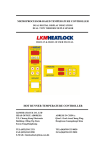
For Technical Assistance in the U.S.,
Call Toll-Free: 800-782-6776
For Technical Assistance Outside the U.S.,
Call: 610-828-2490
SERIES
RMB
HOT RUNNER CONTROLLER
Instruction
Manual
CORPORATE HEADQUARTERS
EUROPE
Athena Controls, Inc.
5145 Campus Drive
Plymouth Meeting, PA 19462 U.S.A.
Tel: (610) 828-2490
Fax: (610) 828-7084
Toll-Free in U.S.: 1-800-782-6776
E-Mail: [email protected]
Internet: www.athenacontrols.com
Athena Controls, Ltd.
P.O. Box 176
Stockport, SK3 0LF
England
Tel: +44 (0) 161 428 9966
Fax: +44 (0) 161 428 9977
E-Mail: [email protected]
Fax (610) 828-7084
Introduction
Thank you for choosing Athena Controls. Congratulations on your purchase.
Used properly, this precision instrument will provide you with many years of
trouble-free and productive service.
The RMB Series zone controllers offer many advanced features designed to
increase productivity and ensure fast, accurate and repeatable mold
temperature control.
!
Compatible with all previous G1 and G+ units and all existing Hot
Runner Controls for easy retrofit/replacement.
Simultaneous display of both process/setpoint temperature and
process temperature/percent power output or heater current.
Autotuning independently adjusts zone control characteristics.
Built-in diagnostics alert operator to fault conditions.
CompuStep® circuitry provides for safe heater warm-up through
gradual phase angle-fired voltage control (Soft Start).
!
!
!
!
While most technical questions concerning the operation of the Series RMB
controllers can be answered by referring to this manual, you may contact
your Athena representative for additional support, or Athena Customer
Service directly, at 800-782-6776 (outside the U.S. call 610-828-2490).
Safety Warning
Precautions
After unpacking, inspect the instrument for any physical damage that may
have occurred in shipping. Save all packing materials and report any
damage to the carrier immediately.
NOTES ON CE EMC COMPLIANCE
In addition to presenting a potential fire hazard, high voltage and high
temperature can damage equipment and cause severe injury or death.
When installing or using this instrument, follow all instructions carefully and
use approved safety controls (high limit, etc.). Only suitably trained
personnel should perform electrical wiring of connections.
Do not locate this instrument where it may be subjected to excessive
shock, vibration, dirt, moisture, oil, or other liquids.
This unit is compliant with the following standards when properly installed
into a grounded metal housing: (EMC testing was conducted with a load
of 1Amp and setpoint of 400°F.)
EMC Directive (89/336/EEC)
EN 50081-1 (1992 edition)
EN 50082-1 (1992 edition)
Low Voltage Directive (73/23/EEC)
EN 61010-1 (1992 edition, Amendments 1, 2, 3, 4 and 11)
Safe operating temperature range is 32 to 131°F (0 to 55°C ).
WARNING
This is a Class A product. In a domestic enviroment this product may
cause radio interference in which case the user may be required to take
adequate measures.
Never insert or remove a controller from a mainframe with the AC power on.
Hazardous potentials exist on components inside the mainframe and
controller. Always disconnect AC power to the mainframe when servicing!
Because these temperature controls or associated equipment may not
always fail safe, an approved temperature and/or pressure safety control
should be used for safe operation.
1
G is a registered trademark of the DME Corporation.
2
© Copyright 1999, Athena Controls, Inc.
Caution
3
Table of
Contents
General
Description
General Description .................................................................... 5
Installation ................................................................................... 6
Jumper Selections ...................................................................... 6
Factory Default Settings .............................................................. 7
Entering and Changing Parameter Values ................................. 8
Parameter Descriptions ............................................................... 9
The Series RMB zone temperature controller is a PID-controlled instrument
specifically designed for runnerless (hot runner) plastic injection molding
applications. The controller is self-adjusting and capable of maintaining a
very high degree of temperature accuracy over a wide range of operating
conditions.
Proportional Bandwidth
Rate
Reset
Autotune
Modes of Operation ..................................................................... 10
Manual Mode
Auto Mode
Functions ..................................................................................... 11
Sensor Sampling
Closed-Loop Control
Open-Loop Control
CompuStep® (Heater Bake-Out)
Output Failure Override Option
Loop-Break Protection
Temperature Indication
Heat-On Indication
Current Monitoring
CompuStep/Bake-Out/Soft-Start
Autotune
Auto Control Mode
Manual Control Mode
Bumpless Transfer
Ground Fault Detection Option
Preset Deviation Alarms
Current Monitor/Output Failure Detection
Sensor Error Detection
Normal Operating Mode Display Functions
Autotune Active Indication
Simplified controls and the use of status indicators allow the operator to
make adjustments easily. The status display also provides visual indication
of normal or abnormal operating conditions existing in both the controller
and/or load.
The RMB is a microcontroller-based “Hot-Runner” family control module that
provides temperature control and operator interface functions. It controls one
temperature zone by sensing a J or K thermocouple (see jumper table). The
RMB’s operator input is via a 4-button keypad. The controller has two
displays consisting of seven-segment LEDs. The upper display is a threecharacter display and the lower display is a four-character display. Additionally, the unit has three discrete LED indicators to indicate system status.
The RMB consists of two electronics boards (microcontroller and display), a
triac/heat-sink assembly, and a front-panel assembly. It is physically and
electrically compatible with the existing Athena mainframe system.
Display and Error Codes ............................................................ 16
Specifications ............................................................................. 17
Warranty ...................................................................................... 18
Repairs and Spare Parts ............................................................ 19
4
5
Installation
Set jumper configuration to desired operation (see jumper table). To install
the controller in a mainframe, release the locking device on the lower edge of
the unit by pulling the plunger gently away from the panel. NOTE: For CE
units use appropriate tool to remove locking screw. Align the upper and lower
edges of the controller printed circuit board with the respective card guides
on the mainframe and slide the unit all the way into the mainframe until the
rear connector is completely engaged. Lock the controller into the frame by
depressing the plunger on the locking device.
Factory
Default Settings
MENU
SETPOINT
AUTOTUNE
PROPORTIONAL BAND
RATE
DEVIATION ALARMS
Jumper
Selections
JUMPERS
JP1
JP2
JP3
6
100 °F (37.8 °C)
ONCE
24
7
+/- 30 °F (+/- 17°C)
SOFT START
SENSOR
CENTIGRADE / FAHRENHEIT
7
Entering and Changing
Parameter Values
Parameter
Descriptions
Process Temperature Display (3 Digit)
PROPORTIONAL BANDWIDTH
Setpoint, Percent Output, or Heater
Current Display (4 Digit)
Proportional Band is the amount of deviation of the controlled variable
required to move through the full range (expressed in % of span or degrees
of temperature). It is an expression of Gain (the wider the band, the lower the
gain.) This item is accessible within the Menu. This PID control parameter is
adjustable from 0.1 to 999 oF/537 oC.
Heat On Indicator (Orange)
Alarm Indicator (Orange)
Up Arrow
Increases temperature setpoint in normal
mode or increases values in menu mode
(Hold for fast-step progression)
Display - Setpoint, Percent Output, or
Heater Current. When held for 3 seconds ,
it displays menu (PID).
Auto / Manual Mode (Green)
(LED On Indicates “Manual”)
Down Arrow
Decreases temperature setpoint in normal
mode or decreases values in menu mode
(Hold for fast-step progression)
Power
(MUST BE OFF TO REMOVE OR
INSTALL UNIT)
RATE
Rate is a control function that produces a corrective signal proportional to
the rate at which the controlled variable is changing. Rate action produces a
faster corrective action than proportional action alone. Also referred to as
Derivative action, Rate is useful in eliminating overshoot and undershoot.
This item is accessible within the Menu. This PID control parameter is
adjustable from 0.0 to 999.
RESET
Reset is a control function that produces a corrective signal proportional to
the length of time and magnitude the controlled variable has been away from
the setpoint. Reset action accommodates load changes, and is also known
as Integral action. This item is not accessible within the Menu as the Reset
parameter tracks the Rate parameter by a fixed ratio.
The PID menu contains three items. Enter the menu by holding down the
DISPLAY KEY for three seconds and pressing the MODE KEY to index
through the parameters. Exit the menu by holding down the DISPLAY KEY
for three seconds.
AUTOTUNE
Pb
rAte
At.OP
EnA
oncE
Proportional Band
Derivative w/tracking integral
Autotune Operation (enable/once/disable)
! To adjust parameters use the up or down keys.
! To select next item in menu use the MODE key.
8
When “At.OP” appears on the display, it will toggle with one of the following.
Press the UP/DOWN keys to change setting.
dlS
ENABLE: Tunes every time power is applied.
ONCE: Tunes the first time power is applied, then reverts
to disable.
DISABLE: Uses currently stored PID values.
9
Modes of
Operation
Functions
SENSOR SAMPLING
Manual Mode
To switch to Manual Mode from Auto Mode, press the MODE key until the
“Manual” LED illuminates. This mode allows the operator to adjust the
Manual Output Percentage (0 to 100%) by pressing the UP/DOWN arrow
keys.
There are two different parameters that can be viewed on the lower display
while in MANUAL mode. Pressing the DISPLAY key will toggle between
them.
1) Manual Control Output Percent (modifiable by user) (display followed
by “P”)
2) Measured Heater Current (display followed by “A”)
A “J” or “K” (OPTIONAL) thermocouple is sampled using a 16-bit dual-slope
integrating A/D converter. Input voltages corresponding to temperatures from
32 to 999 °F (0 to 537 °C) are processed with a resolution of 1 °F (°C).
CLOSED-LOOP CONTROL
A PID control algorithm is used to adjust the amount of power delivered to
the load. The Proportional Band and Derivative (rate) parameters are individually and directly adjustable. The Integral (reset) parameter tracks the
Derivative parameter by a fixed ratio.
OPEN-LOOP CONTROL
In open-loop (MANUAL CONTROL MODE), the operator is able to set the
output percentage.
COMPUSTEP® (HEATER BAKE-OUT)
Graduated phase-angle activation of the triac is provided for drying heaters
on startup.
OUTPUT FAILURE OVERRIDE (OPTIONAL)
Auto Mode
To switch to Auto Mode from Manual Mode, press the MODE key until the
“Manual” LED turns off. This mode allows the operator to adjust the setpoint
temperature value by pressing the UP/DOWN arrow keys.
There are three different parameters that can be viewed on the lower display
while in Auto Mode. Pressing the DISPLAY key will toggle between them.
An optional relay on the RMB is used by the microcontroller to interrupt
current to the load in the event of triac shorting or error condition.
LOOP-BREAK PROTECTION
Software will monitor the response of the system to changes in the output
for the purpose of detecting a control loop break. When this error occurs the
display will read “LPbr”.
TEMPERATURE INDICATION
1) Setpoint value (modifiable by user)
2) Output Percent (display followed by “P”)
Actual process temperature is indicated on the Process Display (upper
display). Units (°F or °C) for this display are determined by a jumper (see
page 6) and displayed on the lower display after the setpoint temperature.
3) Measured Heater Current (display followed by “A”)
HEAT ON INDICATION
A single orange LED is lit whenever the output is on. For additional output
state information, the operator may select to monitor Heater Output
Percentage from the front panel’s lower display. See page 8.
CURRENT MONITORING
10
The RMB is capable of monitoring and displaying the average current being
delivered to the load. The display is in 0.1 ampere increments.
11
Functions (cont’d)
Functions (cont’d)
COMPUSTEP® / BAKE OUT / SOFT START
MANUAL CONTROL MODE
Gradually applying power to the heaters extends the life of the heaters and
the mold. Phase angle firing is used to implement the CompuStep feature.
The CompuStep will last for 5 minutes or until the temperature reaches 200
°F.
Switching between Auto and Manual mode is easily accomplished by
pressing the MODE key to toggle between both states. In Manual mode, the
LED indicator labeled “Manual” is illuminated. In Auto mode, it is not.
Manual control is also activated at zero percent when input error conditions
arise and under these circumstances is activated automatically regardless of
the “MODE” key Enable state. The initial control percent, established when
manual control is activated, is dependent upon the cause of activation.
When entered normally because of operator actions, a bumpless transfer is
attempted. Pressing the “MODE” Key again (when in manual mode) returns
the control to automatic mode.
CompuStep is a self-terminating feature but the operator may also terminate
it by pressing the MODE key.
AUTOTUNE
The Athena® autotune process executes according to the value established
for the autotune parameter in the PID menu (default is to operate “ONCE”).
BUMPLESS TRANSFER
The tune operation will follow CompuStep. The tuner looks for stability in the
process temperature before it proceeds. If system stability cannot be
achieved within a fixed time period then the tune process will terminate. The
operator has the ability to terminate autotuner execution by pressing the
MODE key while the autotuner is active. During autotuning, the display
alternately flashes “tun” and the process value.
The RMB employs an intelligent bumpless transfer. When the process is
within five degrees of setpoint, the controller periodically records the output
percent necessary to maintain setpoint. When an operator initiated transition
to Manual Control occurs, the recorded output percentage is used.
This is adjustable 0 - 100%.
AUTO CONTROL MODE
GROUND FAULT DETECTION OPTION (standard on domestic units)
The default (auto) control mode is PID. The rate and proportional band
parameters appear in the menu system. The reset parameter is always set
to a value equal to five times the rate. The RMB has a fixed cycle time of
100 ms (10 Hz).
If a ground fault is detected during power up and if the unit is below 200 °F
(93.3 ° C) during any operating mode the RMB makes up to three attempts
to use CompuStep® to resolve the problem.
If the ground fault signal is still asserted when the unit is above 200 °F
(93.3 ° C), a steady “gFi” will appear in the lower display, and the Alarm
LED will illuminate. All other indicators will be off and all control processing
will terminate. Power to the unit must be reset to resume control.
12
13
Functions (cont’d)
Functions (cont’d)
PRESET DEVIATION ALARMS
NORMAL OPERATING MODE DISPLAY FUNCTIONS
The RMB provides two deviation alarms, preset to 30 °F or 17 °C above and
below setpoint value. If the process temperature falls below the setpoint
minus the low deviation alarm value, or if the process temperature rises
above the setpoint plus the high deviation alarm value, the controller enters
the alarm state. The Alarm LED will illuminate. A port line is enabled on the
communications connector strip that can be used to activate the audible
alarm on Athena’s ACM or ASM communications module (or similar
module like the mainframe endplate module) if one is included in the system. When a deviation alarm condition occurs, this port is activated.
In the absence of any special circumstances or error conditions, the upper
display (3-character display) of the RMB is dedicated to the presentation of
the Process Value when the unit is in Normal Operating MODE. The
Process Value is displayed in accordance with the temperature scale
established by the “Units” jumper.
In the absence of any error conditions, the lower display (4 character
display) of the RMB is used to present a variety of items. The operator can
index through the available items with brief presses of the DISPLAY key.
CURRENT MONITOR / OUTPUT FAILURE DETECTION
The Current Monitor processor continually monitors heater current readings
to ensure that they correlate with output activity.
If the output device signal (HEAT) is off and a current flow is detected, then
the processor will post a triac short error, the lower display will toggle
between “Out” and “SHrt,” and the Alarm LED will illuminate. All other
indicators will be off, and all control processing will terminate.
If the output device is on but no current flow is detected, then the processor
will post a bad heater error, the lower display will toggle between “bAd” and
“Htr,” and the Alarm LED will illuminate. All other indicators will be off, and all
control processing will terminate.
If either of these error conditions is detected, and the Power Interrupt option
is installed, a relay will open to shut off power between the triac and heater.
AUTOTUNE ACTIVE INDICATION
Whenever the Autotune Process is active, the upper display will alternately
flash between Autotune (tUn) and Process Value.
The Autotune process will terminate when completed, or when an error has
been detected. When autotuning is completed, the flashing Autotune Active
display (tUn) will revert to a steady display of the process value. When the
process self-terminates due to an error condition, the Autotune Active
display will flash alternately with an error code, indicating the specific error
condition that has occurred. (see page 16).
The Autotune process can also be terminated by pressing the Mode key
while the Autotune process is active. The unit will revert to auto control
mode, and the flashing Autotune Active display will be replaced with a
steady readout of the process value.
There is no automatic recovery from either of these error conditions. Once
detected and posted, power to the unit must be reset for control processing
to resume.
SENSOR ERROR DETECTION
When a sensor error is detected, the upper display will alternately flash
between “TC” and the cause of the thermocouple error. “rEv” occurs if the
thermocouple is reversed, and “oPn” occurs if the thermocouple is open. The
alarm LED will illuminate, and the output will be disabled. When “rEv” or
“oPn” occur, the unit goes into Manual Mode 0%.
14
15
Display and
Error Codes
DISPLAY CODE
Pb
RAte
At.OP
EnA
oncE
dIS
tUn
Specifications
DESCRIPTION
Proportional Band
Derivative w/tracking integral
Autotune Operation (enable/once/disable)
Enable
Once
Disable
Autotuning
ERROR CODE
Err.L
Err.h
gFi
LPbr
SHrt Out (display alternates)
tC
OPn (display alternates)
tC
rEv (display alternates)
Htr
bAd (display alternates)
DESCRIPTION
Input too low
Input too high
Ground Fault
Loop Break
Output Short
Open Thermocouple
Reverse Thermocouple
Open Heater
Operating Temperature
Shipping Temperature
Humidity
Sensor Type (Jumper Selectable)
Sensor Range
Sampling Rate
Noise Rejection
Temperature Accuracy
Repeatability
Displays
Upper Display Height
Lower Display Height
Output Status Indication
Alarm Status Indication
Manual Mode Indicator
Control Output Device Type
Operator Activation/Interface
Power Requirements
32 to 131 °F (0 to 55 °C).
-40 to 158 °F (-40 to 70 °C).
10 to 95% Non-Condensing.
J or K Thermocouple
32 to 999 °F (0 to 537 °C)
10 Hz (100 ms)
Common Mode > 100 dB
Series Mode > 70 dB
±0.3% of span.
± 0.1% of span.
7-Segment LEDs; 3-digit upper
(orange) and 4-digit lower (green)
14.2mm / 0.56”
9.15mm / 0.36”
Orange LED
Orange LED
Green LED
Triac, 15 A at 120/240 Vac
optional 30 A
4 Momentary Switches, 16 A Power
Switch
115 to 240 V 50/60 Hz Nominal
CE Compliant
All specifications are subject to change without notice.
16
17
Two-Year
Limited Warranty
THIS EQUIPMENT IS WARRANTED TO BE FREE FROM DEFECTS OF
MATERIAL AND WORKMANSHIP. IT IS SOLD SUBJECT TO OUR
MUTUAL AGREEMENT THAT THE LIABILITY OF ATHENA CONTROLS,
INCORPORATED IS TO REPLACE OR REPAIR THIS EQUIPMENT AT
ITS FACTORY, PROVIDED THAT IT IS RETURNED WITH
TRANSPORTATION PREPAID WITHIN TWO (2) YEARS OF ITS
PURCHASE.
THE PURCHASER AGREES THAT ATHENA CONTROLS, INCORPORATED ASSUMES NO LIABILITY UNDER ANY CIRCUMSTANCES FOR
CONSEQUENTIAL DAMAGES RESULTING FROM ITS USE OR FROM
IMPROPER HANDLING OR PACKAGING OF SHIPMENTS RETURNED
TO THE FACTORY.
COMPONENTS WHICH WEAR OR WHICH ARE DAMAGED BY MISUSE ARE NOT WARRANTED. THESE INCLUDE CONTACT POINTS,
FUSES, ELECTROMECHANICAL RELAYS, AND TRIACS. UNITS
WHICH HAVE BEEN MODIFIED BY A CUSTOMER IN ANY WAY ARE
NOT WARRANTED.
Other than those expressly stated herein, THERE ARE NO OTHER
WARRANTIES OF ANY KIND, EXPRESS OR IMPLIED, AND
SPECIFICALLY EXCLUDED BUT NOT BY WAY OF LIMITATION, ARE
THE IMPLIED WARRANTIES OF FITNESS FOR A PARTICULAR
PURPOSE AND MERCHANTABILITY.
IT IS UNDERSTOOD AND AGREED THE SELLER’S LIABILITY
WHETHER IN CONTRACT, IN TORT, UNDER ANY WARRANTY, IN
NEGLIGENCE OR OTHERWISE SHALL NOT EXCEED THE RETURN OF
THE AMOUNT OF THE PURCHASE PRICE PAID BY THE PURCHASER
AND UNDER NO CIRCUMSTANCES SHALL SELLER BE LIABLE FOR
SPECIAL, INDIRECT, INCIDENTAL OR CONSEQUENTIAL DAMAGES.
THE PRICE STATED FOR THE EQUIPMENT IS A CONSIDERATION IN
LIMITING SELLER’S LIABILITY. NO ACTION, REGARDLESS OF FORM,
ARISING OUT OF THE TRANSACTIONS OF THIS AGREEMENT MAY
BE BROUGHT BY PURCHASER MORE THAN ONE YEAR AFTER THE
CAUSE OF ACTION HAS ACCRUED.
SELLER’S MAXIMUM LIABILITY SHALL NOT EXCEED AND BUYER’S
REMEDY IS LIMITED TO EITHER (i) REPAIR OR REPLACEMENT OF
THE DEFECTIVE PART OR PRODUCT, OR AT SELLER’S OPTION (ii)
RETURN OF THE PRODUCT AND REFUND OF THE PURCHASE
PRICE, AND SUCH REMEDY SHALL BE BUYER’S ENTIRE AND
EXCLUSIVE REMEDY. THE SPECIFICATIONS PUT FORTH IN THIS
MANUAL ARE SUBJECT TO CHANGE WITHOUT NOTICE.
18
Repairs and
Spare Parts
It is recommended that units requiring service be returned to an authorized
service center. Before a controller is returned for service, please consult the
service center nearest you. In many cases, the problem can be cleared up
over the telephone. When the unit needs to be returned, the service center
will ask for a detailed explanation of problems encountered and a Purchase
Order to cover any charge. This information should also be put in the box
with the unit. This should expedite return of the unit to you.
SPARE PARTS
A spare parts list can be supplied upon request if the complete model
number is supplied.
DISCLAIMER
This document is based on information available at the time of its publication. While efforts have been made to render accuracy to its content, the
information contained herein does not purport to cover all details or variations
in the hardware, nor to provide for every possible contingency in connection
with the installation and maintenance. Features may be described herein
which are not present in all hardware. Athena Controls assumes no obligation of notice to holders of this document with respect to changes subsequently made.
Proprietary information of Athena Controls, Incorporated is furnished for
customer use only. No other use is authorized without the written permission of Athena Controls, Incorporated.
Part Number: 900M046U00 Revision “A”
19