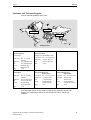
1
Preface, Table of Contents
SIMATIC HMI
Panel PC 670
Panel PC 870
Commissioning Instructions
Edition 11/01
A5E00135748-01
Installing and Connecting
the Panel PC 670/870
1
Notes on the
Panel PC 670/870
2
Setting Up and Operating
Panel PC 670/870
3
Electromagnetic Compatibility
4
Appendix
Safety Guidelines
This manual contains notices which you should observe to ensure your own personal safety, as
well as to protect the product and connected equipment. These notices are marked as follows
according to the level of danger:
Danger
indicates an imminently hazardous situation which, if not avoided, will result in death or serious
injury.
Warning
indicates a potentially hazardous situation which, if not avoided, could result in death or serious
injury.
Caution
used with the safety alert symbol indicates a potentially hazardous situation which, if not avoided,
may result in minor or moderate injury.
Caution
used without safety alert symbol indicates a potentially hazardous situation which, if not avoided,
may result in property damage.
Attention
indicates that unwanted events or status can occur if the relevant information is not observed.
Note
draws your attention to particularly important information on the product, handling the product, or to
a particular part of the documentation.
Qualified Personnel
Equipment may be commissioned and operated only by qualified personnel. Qualified personnel
within the meaning of the safety notices in this manual are persons who are authorized to
commission, ground and identify equipment, systems and circuits in accordance with safety
engeneering standards.
Correct Usage
Note the following:
Warning
The equipment may be used only for the applications stipulated in the catalog and in the technical
description and only in conjunction with other equipment and components recommended or
approved by Siemens.
Startup must not take place until it is established that the machine, which is to accommodate this
component, is in conformity with the guideline 98/37 ECC.
Faultless and safe operation of the product presupposes proper transportation, proper storage,
erection and installation as well as careful operation and maintenance.
Trademarks
The registered trademarks of the Siemens AG can be found in the preface. The remaining
trademarks in this publication may be trademarks, whose use by third parties for their own
purposes could violate the rights of the owner.
Impressum
Editor and Publisher: A&D PT1 D1
Copyright Siemens AG 2001 All rights reserved
Exclusion of liability
The transmission and reproduction of this documentation and the exploitation and
communication of its contents are not allowed, unless expressly granted. Violators are
liable for damages. All rights reserved, especially in the case of the granting of a
patent or registration by GM.
We have checked the content of this publication for compliance with the described
hard and software. However, discrepancies cannot be excluded, with the result that
we assume no guarantee for total compliance. The information in this publication is
checked regularly, and any necessary corrections are included in the following
editions. We would be grateful for any suggestions for improvement.
Siemens AG
Bereich Automation & Drives
Geschäftsgebiet SIMATIC HMI
Postfach 4848, D-90327 Nuernberg
ã Siemens AG 2001
Technical data subject to change.
Siemens Aktiengesellschaft
Order number A5E00135748-01
1Preface
Purpose
This Commissioning Instruction manual is a component part of the
documentation for the SIMATIC Panel PC 670 and SIMATIC Panel PC 870
(subsequently referred to as Panel PC 670/870). It provides installation
engineers, system operators and maintenance staff with information concerning
installing and commissioning the Panel PC 670/870.
Caution
The contents of the Commissioning Instructions of the Panel PC 670/870 are
superordinated to those of the Equipment Manual of the Panel PC 670/870.
Siemens AG assumes no liability resulting from failure to observe the
instructions.
Documentation
• Commissioning Instructions (this document)
The startup instructions are supplied on paper. It is directed at startup
personnel and system administrators.
The commissioning instructions briefly describe the major steps required for
starting up the hardware and software.
• SIMATIC Panel PC 670, Operating Unit, Equipment Manual
SIMATIC Panel PC 870, Operating Unit, Equipment Manual
This manual is supplied in electronic form with the Panel PC 670/870 in
PDF format on CD. The device manual is directed at startup personnel and
service/maintenance technicians, who install the Panel PC and perform
maintenance tasks on the operating unit.
In addition, the device manual provides an overview of the application of the
operating unit's control elements.
• SIMATIC Panel PC 670, Computer Unit, Equipment Manual
SIMATIC Panel PC 870, Computer Unit, Equipment Manual
The manual is supplied in electronic form with the Panel PC 670/870 in PDF
format on CD. It is directed at startup personnel and service/maintenance
technicians who install expansions or perform error analyses on the
computer unit.
SIMATIC Panel PC 670/870 Commissioning Instructions
A5E00135748-01
i
Preface
11/01
Notation
Different font formats simplify orientation within the text:
The text on the screen of the operating unit is displayed in
typewriter font.
Inputs and outputs on the screen of the operating unit are
displayed in italic typewriter font.
Menu items, dialog names, tab controls and buttons of the
operating system and the application are displayed in italic
font.
In context with menu items, the complete path is always
described.
Motor on
Output
File → Edit
Trademarks
The following names are registered trademarks of the Siemens AG:
•
•
•
•
•
•
•
•
•
•
•
ii
®
SIMATIC
®
SIMATIC HMI
®
SIMATIC Multi Panel
®
SIMATIC Multifunctional Platform
®
SIMATIC Panel PC
®
HMI
®
MP 270
®
ProAgent
®
ProTool
®
ProTool/Lite
®
ProTool/Pro
SIMATIC Panel PC 670/870 Commissioning Instructions
A5E00135748-01
11/01
Preface
Customer and Technical Support
Can be reached worldwide at any time:
Nuernberg
Johnson City
Singapore
SIMATIC Hotline
Worldwide (Nuernberg)
Worldwide (Nuernberg)
Technical Support
Technical Support
(FreeContact)
(charged, only with SIMATIC Card)
Local Time:
Mo. - Fr. 7:00 AM 5:00 PM
Telephone:
+49 (180) 5050-222
Fax:
+49 (180) 5050-223
E-mail:
techsupport@
ad.siemens.de
GMT:
+1:00
Local Time:
Mo. - Fr. 0:00 to 24:00
Telephone:
+49 (911) 895-7777
Fax:
+49 (911) 895-7001
GMT:
+01:00
Europe/Africa (Nuernberg)
America (Johnson City)
Asia/Australia (Singapore)
Authorization
Technical Support and
Authorization
Technical Support and
Authorization
Local Time:
Mo. - Fr. 7:00 AM 5:00 PM
Local Time:
Mo. - Fr. 8:00 to 19:00
Local Time:
Telephone:
+1 423 461-2522
Telephone:
+65 740-7000
Telephone:
+49 (911) 895-7200
Fax:
+1 423 461-2289
Fax:
+65 740-7001
Fax:
+49 (911) 895-7201
E-mail:
authorization@
nbgm.siemens.de
simatic.hotline@
sea.siemens.com
E-mail:
E-mail:
simatic.hotline@
sae.siemens.com.sg
GMT:
-5:00
GMT:
+8:00
GMT:
+1:00
Mo. - Fr. 8:30 to 17:30
The languages spoken by the SIMATIC Hotlines are generally German and
English, the Authorization Hotline is also provided in French, Italian and
Spanish.
SIMATIC Panel PC 670/870 Commissioning Instructions
A5E00135748-01
iii
Preface
11/01
Other support
In the case of technical queries, please contact the Siemens representatives in
the subsidiaries and branches responsible for your area.
SIMATIC Customer Support Online Services
The SIMATIC Customer Support provides you with additional information about
SIMATIC products through online services:
• General and current information can be obtained
–
In the Internet under http://www.ad.siemens.de/simatic
• Latest product information and downloads can be found
–
in the Internet under http://www.ad.siemens.de/simatic-cs and
–
via the Bulletin Board System (BBS) in Nürnberg (SIMATIC Customer
Support Mailbox) under the number +49 (911) 895-7100.
To dial the mailbox, use a modem with a capacity up to
V.34 (28.8 kBaud) whose parameters are set as follows:
– 8, N, 1, ANSI or
– dial via ISDN (x.75, 64 kBit).
• Your contact partner for Automation & Drives can be found in the contact
partner database
–
iv
in the Internet under http://www3.ad.siemens.de/partner/search.asp
SIMATIC Panel PC 670/870 Commissioning Instructions
A5E00135748-01
Table of Contents
1
Installing and Connecting the Panel PC 670/870............................. 1–1
1.1
1.2
1.3
1.4
1.5
1.6
2
Notes on the Panel PC 670/870 ......................................................... 2–1
2.1
2.2
2.3
2.4
2.5
2.6
3
General Information ......................................................................................... 2–1
Panel PC 670/870 – Touchscreen Version...................................................... 2–2
Panel PC 670 – Windows 98 ........................................................................... 2–6
Panel PC 670/870 – Windows NT 4.0 ............................................................. 2–8
Panel PC 670/870 – Windows 2000 .............................................................. 2–10
Panel PC 870 – Without Operating System................................................... 2–14
Setting Up and Operating Panel PC 670/870 ................................... 3–1
3.1
3.2
3.3
3.4
4
Unpacking and Checking the Delivery Contents ............................................. 1–1
Installation of the Panel PC 670/870................................................................ 1–2
Operating Units with Keyboard Fronts ............................................................. 1–7
Operating Units with Touchscreen Fronts........................................................ 1–8
Use of USB Peripheral Devices ....................................................................... 1–9
Connection to the Power Supply.................................................................... 1–11
Initial Startup and Normal Operation................................................................ 3–1
Data Backup..................................................................................................... 3–2
Restart.............................................................................................................. 3–3
Installation of Drivers........................................................................................ 3–3
Electromagnetic Compatibility.......................................................... 4–1
Appendix................................................................................................. a
SIMATIC Panel PC 670/870 Commissioning Instructions
A5E00135748-01
v
Table of Contents
vi
11/01
SIMATIC Panel PC 670/870 Commissioning Instructions
A5E00135748-01
1
Installing and Connecting the
Panel PC 670/870
1.1
Unpacking and Checking the Delivery Contents
Unpacking
• Check the packaging of the Panel PC 670/870 for visible signs of transport
damage.
• Remove the packaging.
Note
Do not dispose of the original packaging – save it for a future transportation of the
Panel PC 670/870.
Keep all the documents supplied! They belong to the Panel PC 670/870 and are
required for the initial startup.
Checking
• Check the contents of the packaging for visible signs of transport damage.
• Should you find any transport damage on the Panel PC 670/870, contact your
sales outlet immediately.
Registering device numbers
Enter the SVP number (production number) and the MLFB number of the
Panel PC 670/870 into the following table.
Both numbers are on the rating plate located on the top of the unit on the right side.
SVP number
MLFB number
SIMATIC Panel PC 670/870 Commissioning Instructions
A5E00135748-01
1–1
Installing and Connecting the Panel PC 670/870
11/01
The SVP number and the MLFB number enable the device to be identified by the
service center in case of any repairs required.
MLFB number
Figure 1–1
1.2
SVP number
Model Edition,
Power Supply
Rating Plate
Installation of the Panel PC 670/870
Note
The Panel PC 670/870 is approved for operation in closed rooms.
When installing the Panel PC 670/870 observe the Chapter "Technical Data" of the
Panel PC 670 or Panel PC 870 Equipment Manual as well as the following points:
• Place the screen in such a way that it is not exposed to direct radiation by
sunlight or other light sources.
• Place the screen in an ergonomic position for the user; select a corresponding
installation height.
• The installation should not cover the ventilation openings in the case.
• Ensure that the cabinet/panel has sufficient volume for the air exchange. The
free space around the Panel PC 670/870 must be at least 100 mm. A free
space of 10 mm is permissible on the rear side.
The maximum air inlet temperature must not exceed 45 °C when the unit is
operating at maximum capacity.
• Observe the proper installation positions of the Panel PC 670/870.
1–2
SIMATIC Panel PC 670/870 Commissioning Instructions
A5E00135748-01
11/01
Installing and Connecting the Panel PC 670/870
Installation position
Warning
If the Panel PC 670/870 is installed in a position which is not permissible, all
approvals complying with UL 1950 and EN 60950 are annulled.
The permissible installation positions depend on the computer unit mounted.
The following installation positions are possible for the Panel PC 670/870:
+20° –20°
Figure 1–2
Permissible Installation Positions of the Panel PC 670/870
Vertical installation and deviations up to ±20° in the indicated directions are
permitted.
SIMATIC Panel PC 670/870 Commissioning Instructions
A5E00135748-01
1–3
Installing and Connecting the Panel PC 670/870
11/01
Installation cut-out
When selecting the installation cut-out, ensure that the switching cabinet/panel
contains reinforcement bars to stabilize the plate. If necessary, install such
reinforcement bars.
An installation cut-out is required corresponding to the following diagram:
2 to 6
2
H+1
B+1
T+1
Unit depth T
Installation cut-out
B
H
PC 670
PC 870
Panel PC 670/870, 12", Keys
Panel PC 670/870, 15", Keys
450
450
295 ± 0,5
326 ± 0,5
114
142
202
227
Panel PC 670/870, 12", Touch
Panel PC 670/870, 15", Touch
368
450
290
290
–
137
–
229
Figure 1–3
Unit depth T
All figures in mm.
Installation Cut-out for Standard Installation
Specifications without the CD-ROM option.
Note
Ensure sufficient air volume for heat transportation within the switching
cabinet/panel. There must be at least 100 mm free space around the
Panel PC 670/870. 10 mm are permissible on the rear side.
Also ensure sufficient free space to pull out the Panel PC 670/870 from the
installation cut-out.
1–4
SIMATIC Panel PC 670/870 Commissioning Instructions
A5E00135748-01
11/01
Installing and Connecting the Panel PC 670/870
Installation
The operating unit can be mounted in the installation cut-out either with clamp
saddles or screw mountings. Fixation using screw mountings is not possible for the
12” touch screen model.
Fixation using clamping saddles, in conjunction with a continuous seal, meets the
requirements for IP65 Degree of Protection.
Installations using bolts meet the IP 54 Degree of Protection.
Installation positions and dimensions
The permissible installation positions are dependent on the Panel PC type
installed.
Threaded
Befestigungsspannbügel mit
clamping saddle
Gewindestiften
A2 ± 1
A1 ± 1
L5 ± 0,2
Pressure
points für
for
Druckpunkte
clamping saddle
Befestigungsspannbügel
Rz 120
L4 ± 0,2
Vorderseite:
Dichtungsbereich
bzw.
Front
side: seal
area
Rückseite:
Bereich saddle
für Befestigungsspannbügel
Rear
side: clamping
area
Screw
Mounting and Sealing
Area
Schraubbefestigung
und Dichtungsbereich
Within
the seal area
Im Dichtungsbereich
L4
L5
A1
A2
Panel PC 670/870, 12", Keys
Tasten
Panel PC 670/870, 15", Keys
Tasten
465
465
235
279
16
16
10
17
Panel PC 670/870, 12", Touch
Panel PC 670/870, 15", Touch
–
465
–
235
16
16
10
10
Angaben
in mm.
AllAlle
figures
in mm.
Figure1–4
Dimensions for Installation of the Operating Unit
SIMATIC Panel PC 670/870 Commissioning Instructions
A5E00135748-01
1–5
Installing and Connecting the Panel PC 670/870
11/01
Installation using clamps
For the installation, use the clamps with screw fittings supplied. Proceed as follows:
1. Install the assembled operating unit and computer unit components in the
prepared installation cut-out from the front.
2. From the back, fasten the operating unit in the installation cut-out by tightening
the setscrews (torque: 0.4 - 0.5 Nm) of the six clamps (see Figure 2–2).
Installation Using Screw Mountings
Note
The Panel PC 670/870 12" touchscreen is not designed for installation using screw
mountings.
Proceed as follows:
1. Drill appropriate holes around the prepared installation cut-out in accordance
with the specifications to L4 and L5 in Figure1–4.
2. Carefully break out the drill hole caps on the front of the operating unit.
Drill hole caps
Figure 1–5
Drill Holes with Caps
3. Install the assembled operating unit and computer unit components in the
prepared installation cut-out from the front.
4. Fasten the operating unit with suitable nuts and bolts through the drill holes.
The installation with bolts meets the IP 54 Degree of Protection.
1–6
SIMATIC Panel PC 670/870 Commissioning Instructions
A5E00135748-01
11/01
1.3
Installing and Connecting the Panel PC 670/870
Operating Units with Keyboard Fronts
The front side of the Panel PC 670/870 is equipped with a membrane keyboard
and mouse.
The integrated USB mouse with two mouse buttons is a "piezo mouse", i.e. the
direction of the mouse pointer movement is controlled by the position of pressure
on the pressure surface, while the speed of the mouse pointer movement is
controlled by the force of pressure applied.
Optionally, an external mouse can be connected to the USB port at the front. The
piezo mouse remains active in this case.
The arrangement of the operating elements is illustrated in Figure 2–5.
Status indicators
Function keys/Softkeys
Alphanumeric, cursor and
control keys
Display
USB interface
Figure 1–6
Integrated mouse
Front View of the Operating Unit
Note
The Panel PC 670/870 Documentation & Drivers CD contains several master files
to create labeling strips with which to label the keys. These labeling strips can be
edited and printed using MS Word or Coral Draw.
SIMATIC Panel PC 670/870 Commissioning Instructions
A5E00135748-01
1–7
Installing and Connecting the Panel PC 670/870
1.4
11/01
Operating Units with Touchscreen Fronts
The 12” and 15” versions with touchscreen fronts differ with regard to their
dimensions and display sizes. The 12” model has no drill hole caps on the side.
Figure 2–6 illustrates an example of the 15” model with indicator lights, USB port
and display.
Status indicators
Display
USB interface
Figure 1–7
Example of a 15” Operating Unit with Touchscreen Front
Operation
The device is operated by touching the touch-sensitive screen which contains
application-specific functions, e.g. touching a button displayed.
1–8
SIMATIC Panel PC 670/870 Commissioning Instructions
A5E00135748-01
11/01
1.5
Installing and Connecting the Panel PC 670/870
Use of USB Peripheral Devices
Panel PC 670/870 – Windows NT 4.0 with USB Stack
The operating system manufacturer does not support USB in the case of
Windows NT 4.0. In order to use the integrated mouse and the membrane
keyboard with the Windows NT 4.0 operating system, the Panel PC 670/870 has
been extended by the introduction of USB driver software. This extension makes
the internal keyboard and mouse operational.
Only external USB keyboards with integrated HUB, which fulfill the USB
specification 1.1, and standard USB mice (without any special additional
functionality such as scroll wheel) are approved for connection to the USB interface
at the front and the USB interface on the computer.
Notice
In order to be able to use the additional functions provided by the USB driver, the
menu item USB Legacy Support must be set to Disabled in the BIOS.
Panel PC 670 – Windows 98/Windows 2000
The Panel PC 670 has a USB (Universal Serial Bus) interface integrated on the
front and back.
The USB interface is a flexible and easy way to use standard USB peripheral
components.
For example, either an external USB-capable keyboard or USB-capable mouse
can be connected to this port in additional to the keyboard and mouse already
integrated. If the USB-capable keyboard is also equipped with an external USB
port (USB hub), other USB-capable devices (e.g. mouse) can be connected to it.
Note
When using standard USB peripheral devices, note that their electromagnetic
interference immunity is often only sufficient for office environments. Such devices
are adequate for startup and maintenance purposes. However, components
suitable for an industrial environment must be used for the process operation.
The USB peripheral devices (e.g. keyboard, printer) are developed and marketed
by individual vendors. Support for the USB periphery devices is provided via the
respective product supplier. The terms of liability of the individual vendors or
suppliers apply.
The following types of USB peripheral devices can be distinguished:
•
•
low power USB components:
max. 100 mA current; e.g. mouse, keyboard,
high power USB components:
max. 500 mA current; e.g. hard disk, floppy drive etc.
SIMATIC Panel PC 670/870 Commissioning Instructions
A5E00135748-01
1–9
Installing and Connecting the Panel PC 670/870
11/01
In the case of Panel PC 670 with power supply up to model edition C (refer to the
rating plate, Figure 1–1), the following applies:
• High power USB devices can only be used with the front USB port of the Panel
PC 670 if those devices have their own power supply or the devices are
connected via an external USB hub with a separate power supply.
• This restriction is not applicable for devices with a power supply from model
edition D (refer to rating plate).
Panel PC 870 – Windows 2000
The Panel PC 870 has one USB interface on the front and two on the back.
The USB interface is a flexible and easy way to use standard USB peripheral
components.
In this way, for example, an external USB-compliant keyboard and mouse can be
connected. If the USB-capable keyboard is also equipped with an external USB
port (USB hub), other USB-capable devices (e.g. mouse) can be connected to it.
Notice
Only disconnect the plugs from the USB periphery devices after the Panel PC 870
operating system has been terminated.
Note
When using standard USB peripheral devices, note that their electromagnetic
interference immunity is often only sufficient for office environments. Such devices
are adequate for startup and maintenance purposes. However, components
suitable for an industrial environment must be used for the process operation.
The USB peripheral devices (e.g. keyboard, printer) are developed and marketed
by individual vendors. Support for the USB periphery devices is provided via the
respective product supplier. The terms of liability of the individual vendors or
suppliers apply.
USB periphery devices with a power consumption of up to 500 mA can be
connected to the Panel PC 870.
1–10
SIMATIC Panel PC 670/870 Commissioning Instructions
A5E00135748-01
11/01
1.6
Installing and Connecting the Panel PC 670/870
Connection to the Power Supply
The Panel PC 670/870 can be operated on 120/230 V AC power supplies using the
power cable provided. The voltage selection is performed automatically.
Plug the supplied power cable into the device's socket. Plug the power cable into a
grounded outlet. The device is now in operation.
Danger
Since the device does not possess a power switch, turning off and completely
disconnecting power requires pulling the power plug.
This location should be easily accessible. In the case of installation in a cabinet, a
central power disconnect switch must be provided.
To prevent an unintentional unplugging of the power plug, we recommend using
the power plug lock contained in the accessories kit.
The device can also be supplied with a 24 V DC power supply, according to the
order option. Plug the 3-point power supply connector into the socket on the Panel
PC 670/870. Note the pin assignment depicted on the housing.
Danger
Since the device does not possess an on-off switch, the power plug must be
disconnected from the power supply socket to switch off and completely disconnect
the power supply.
SIMATIC Panel PC 670/870 Commissioning Instructions
A5E00135748-01
1–11
Installing and Connecting the Panel PC 670/870
1–12
11/01
SIMATIC Panel PC 670/870 Commissioning Instructions
A5E00135748-01
2
Notes on the Panel PC 670/870
2.1
General Information
Operating systems
The Panel PC 670/870 is approved for the following operating systems:
Panel PC 670
• Windows 98 SE, German/English
• Windows NT 4.0 with USB driver extension, German/English
• Windows 2000 Professional Multi-Language;
German, English, French, Italian, Spanish
Panel PC 870
• Windows NT 4.0 with USB driver extension, German/English
• Windows 2000 Professional Multi-Language;
German, English, French, Italian, Spanish
Note
The Recovery-CD can be used for the installation or restoring one of these
operating systems. Only those drivers required for that specific operating system
are installed.
Keyboard
The layout of the membrane keyboard is USA International. Please ensure that the
layout of any other keyboard that may be connected also complies with this
character set. Only those characters inscribed on the external keyboard match
those displayed on the screen.
Danger
Simultaneously pressing more than one function key can trigger malfunctions on
the Panel PC 670/870.
Only press the function keys and softkeys in succession (refer to Figure 1–6).
SIMATIC Panel PC 670/870 Commissioning Instructions
A5E00135748-01
2–1
Notes on the Panel PC 670/870
11/01
USB interfaces
2.2
Panel PC 670
operating system
With membrane
keyboard
With
touchscreen
Windows 98 SE, German/English
Yes
Yes
Windows NT 4.0 with USB driver
extension, German/English
With restrictions
Windows 2000 Professional MultiLanguage
Yes
Panel PC 870
operating system
With membrane
keyboard
With
touchscreen
Windows NT 4.0 with USB driver
extension, German/English
With restrictions
With restrictions
Windows 2000 Professional MultiLanguage
Yes
2
3
2)
3
1
With restrictions
2)
Yes
3
2)
Yes
3
Panel PC 670/870 – Touchscreen Version
The following information is applicable to the following operating systems:
• Windows 98 (not Panel PC 870)
• Windows NT 4.0
• Windows 2000
Initial startup
When a Panel PC 670/870 is started up for the first time, the system may request
entry of the appropriate OEM license number during the operating system boot
routine. This number is stuck on the Panel PC 670/870.
Please note that an external keyboard (PS/2 or USB) is required when specifying
the license number. The external keyboard must be connected to the Panel
PC 670/870 before switching the power on.
After entering the license number and the first logon, a prompt appears on the
screen requesting calibration of the touchscreen.
Note
Please allow the Panel PC 670/870 to warm up for a few minutes prior to
calibration.
1
2
3
2–2
In the case of installation of unknown USB devices, it is recommended to use an external keyboard and mouse.
For connection to the USB interfaces, only external USB keyboards without integrated HUB and standard USB
mouse (without special, additional functionality, e.g. scroll wheel) are approved.
Log off the USB device from the operating system before pulling the plug.
SIMATIC Panel PC 670/870 Commissioning Instructions
A5E00135748-01
11/01
Notes on the Panel PC 670/870
Confirm using the external keyboard and then follow the instructions provided by
the application.
Touchware settings
User-specific touchware settings can be defined via the settings Touch Settings
and Tools in the Touchware (refer to Figure 2–1). The MicroTouch Touchscreen
Properties window can be called in via the MicroTouch TouchWare icon located on
the desktop or via the menu sequence Start → Settings → Control Panel →
MicroTouch Touchscreen.
1. Select the Touch Settings tab control. The following window appears:
Figure 2–1
MicroTouch Touchscreen Properties
Note
Explanatory text concerning the buttons provided in the following windows can be
called in by pressing the Help button.
2. Define the Touch Settings.
3. Select the tab control Tools, and press the Options button. The MicroTouch
Touchscreen Options window opens.
4. Select the Advanced button. The following window appears:
SIMATIC Panel PC 670/870 Commissioning Instructions
A5E00135748-01
2–3
Notes on the Panel PC 670/870
Figure 2–2
11/01
Advanced Touchscreen Settings
5. Select the option 2 Point for Calibration Style.
6. Activate the checkboxes as depicted in Figure 2–2.
7. Confirm the input twice using Close.
8. Select the Calibrate tab control.
Figure 2–3
Calibrate
9. Select the Calibrate button.
A window for touch calibration appears.
2–4
SIMATIC Panel PC 670/870 Commissioning Instructions
A5E00135748-01
11/01
Notes on the Panel PC 670/870
10. Touch the touchscreen at the cross-hairs.
During calibration, two cross-hairs are displayed which must be pressed for a
minimum of 3 sec. to a maximum of 10 sec. Finally, the Calibration Complete
window appears.
11. Press the Done button to terminate the calibration process.
Special features
The touch controller, integrated in the front, is designed to automatically
compensate for changes in the surface tensions of the touch sensor (e.g. due to
large temperature fluctuations). As a consequence, however, this feature may
initiate an automatic calibration when exactly the same point is continually pressed
for a while (>15 seconds).
If this happens,
After releasing the screen and allowing a short operating pause, the system is
automatically recalibrated to its original state.
An incidentally located background function is activated by the software
ProTool/Pro if touched when setting the touch parameters in the window
Microtouch → Touchsettings: Desktop or when the screen saver is activated.
Warning
Do not touch the screen:
• during the PC boot routine (until the acoustic BEEP signal),
• when plugging USB components in or out, and
• if the warning message Do not touch the screen... appears. Wait at
least 1 second after the message has disappeared.
SIMATIC Panel PC 670/870 Commissioning Instructions
A5E00135748-01
2–5
Notes on the Panel PC 670/870
2.3
11/01
Panel PC 670 – Windows 98
When the Panel PC 670 is started up for the first time, the system requests entry of
the appropriate OEM license number during the operating system boot routine.
This number is adhered to the device. After entering the license number, enter a
name for the computer so that it can be identified within a network.
Special features
The Panel PC 670 is shipped with BIOS setting LEGACY SUPPORT DISABLED.
This means the full functional range of a USB keyboard is not available during the
initial boot sequence (before Windows is started). There are no restrictions for
using a USB keyboard to make changes in the BIOS Setup. When using a touch
panel, changes can only be made to the BIOS using an externally connected USB
or PS/2 keyboard.
Notice
If Legacy Support is disabled in the BIOS, problems may occur with ISA/PCI
extension boards.
After improper operation, a faulty shutdown of the system or after a loss of power,
the Panel PC 670/870 starts the Scandisk program during the subsequent boot
routine. It is not possible for the user to stop this automatically started program
using an integrated membrane keyboard or external USB keyboard.
The following steps are recommended in order to interrupt this automatic process:
1. When Scandisk has been completed, switch the device off and on again.
Windows reboots without any keyboard input.
If Windows is not rebooted, switch the device off again. Carry out the following
steps:
2. Plug in the USB keyboard and switch on the power supply.
3. Press the "F2" key during the boot routine.
4. Select Hardware Options in the BIOS Setup and switch the LEGACY
SUPPORT setting to ENABLED.
The USB keyboard is also supported in Enabled mode. It is possible to
deactivate Enabled mode again.
5. After rebooting the system again, select Hardware Options in the BIOS
Setup and switch LEGACY SUPPORT back to DISABLED.
If Windows 98 is terminated and Start in MS DOS Mode is selected, input is
only possible using an external PS/2 keyboard.
Power management
The default Power Saving setting Disabled must not be changed in the BIOS
setup.
2–6
SIMATIC Panel PC 670/870 Commissioning Instructions
A5E00135748-01
11/01
Notes on the Panel PC 670/870
Keypad
The Keypad tool in Windows 98 can be used to alter the predefined key
assignments for the membrane keyboard (refer to the directory
drivers.w98/keypad).
The screen brightness can be adjusted using the Setbrightness tool in Windows 98
(refer to the directory drivers.w98/setbrightness).
Keyhook (Version 1.0) for WinCC
Functioning method
The function keys F13 to F20 and S1 to S12 issue key combinations. Pressing the
F13 button, for example, represents pressing the key combination Shift, F1 and
releasing it represents the key combination Shift, F1. A different sequence of key
combinations may be necessary for certain software products. Using the Keyhook
tool, the Makecode "Shift, F1" and Breakcode "Shift, F1" are changed to Makecode
"Shift, F1" and Breakcode "F1, Shift
Installation
Call in the Keyhook Setup in order to install it.
SIMATIC Panel PC 670/870 Commissioning Instructions
A5E00135748-01
2–7
Notes on the Panel PC 670/870
2.4
11/01
Panel PC 670/870 – Windows NT 4.0
Notice
Do not forget that, when installing or restoring Windows NT 4.0, SP5 or higher
must also be installed.
The DHCP utility is set up during the installation of Windows NT. It is predefined as
disabled.
If the DHCP utility is to be used, it must be activated.
1. Select the buttons Start → Settings → Control Panel → Utilities. The Utilities
window opens.
2. Select DHCP Client Utility. Double-clicking on it opens the Utility window.
3. Select the Automatic option button and confirm the selection with OK.
4. Close the window which is open.
Check the entries relating to the computer name after ending the network
configuration.
1. Select the buttons Start → Settings → Control Panel → Network → Protocols.
2. Select TCP/IP. A double-click opens the Microsoft TCP/IP Properties window.
3. Select the DNS tab control, then the Automatic option button and confirm the
selections with OK.
4. The Host Name field contains the computer name; correct it as necessary and
confirm using OK.
When a Panel PC 670/870 is started up for the first time, the system may request
entry of the appropriate OEM license number during the operating system boot
routine. This number is adhered to the device. After entering the license number,
enter a name for the computer so that it can be identified within a network. It is
advisable to enter an administrator password when using Microsoft Windows NT
4.0.
Auto logon
If Auto Logon should be activated, set the following.
Log on as system administrator:
1. Select Start → Settings → Control Panel → Users and Passwords:
2. Deactivate the check box Users must enter user name and password for the
computer.
3. Apply the settings and enter the password.
2–8
SIMATIC Panel PC 670/870 Commissioning Instructions
A5E00135748-01
11/01
Notes on the Panel PC 670/870
Special features
The Panel PC 670/870 is shipped with BIOS setting LEGACY SUPPORT
DISABLED. This means the full functional range of a USB keyboard is not available
during the initial boot sequence (before Windows is started). There are no
restrictions for using a USB keyboard to make changes in the BIOS Setup. When
using a touch panel, changes can only be made to the BIOS using an externally
connected USB or PS/2 keyboard.
Notice
If Legacy Support is disabled in the BIOS, problems may occur with ISA/PCI
extension boards.
The USB Legacy Support is preset to DISABLED in the BIOS Setup under
menu item Hardware.
The Windows NT 4.0 USB driver extension for use of the integrated membrane
keyboard, mouse, and touchscreen has already been pre-installed.
Selection of an operating menu when starting Windows NT 4.0 is only possible with
an external PS/2 keyboard or by changing the BIOS option USB Legacy
Support to ENABLED.
Power management
The default Power Saving setting Disabled must not be changed in the BIOS
setup.
Restrictions
Only applicable to Panel PC 670/870 with keyboard front panels:
• The LEDs on an externally connected PS/2 keyboard have no function.
• The LEDs in the integrated function keys are not supported with
Windows NT 4.0.
• No keyboard code tables can be loaded.
• The brightness of the back-lighting cannot be altered.
• Only external USB keyboards without integrated HUB or standard USB mice
(without special, additional functionality, e.g. scroll wheel) are approved for
connection to the front side USB interface and the USB interface on the
computer.
SIMATIC Panel PC 670/870 Commissioning Instructions
A5E00135748-01
2–9
Notes on the Panel PC 670/870
2.5
11/01
Panel PC 670/870 – Windows 2000
If external PS/2 and USB keyboards are used at the same time, it is possible that
the keyboard LEDs are not updated correctly.
When a Panel PC 670/870 is started up for the first time, the system may request
entry of the appropriate license number during the operating system boot routine.
After entering the license number, enter a name for the computer so that it can be
identified within a network. It is advisable to enter an administrator password under
Microsoft Windows 2000.
Auto logon
Auto Logon is a tool which can be used to start the operating system without calling
in the Logon window.
If Auto Logon should be activated, set the following.
Log on as system administrator:
1. Select Start → Settings → Control Panel → Users and Passwords:
2. Deactivate the check box Users must enter user name and password for the
computer.
3. Apply the settings and enter the password.
Special features
The Panel PC 670/870 is shipped with BIOS setting LEGACY SUPPORT
DISABLED. This means the full functional range of a USB keyboard is not available
during the initial boot sequence (before Windows is started). There are no
restrictions for using a USB keyboard to make changes in the BIOS Setup. When
using a touch panel, changes can only be made to the BIOS using an externally
connected USB or PS/2 keyboard.
Notice
If Legacy Support is disabled in the BIOS, problems may occur with ISA/PCI
extension boards.
The USB Legacy Support is preset to DISABLED in the BIOS Setup under
menu item Hardware.
Set brightness
Only applies to Panel PC 870
The intensity of the back-lighting can be adjusted by using the Setbrightness
software tool.
In order to use the functions provided by Setbrightness, the application must be
installed. Call in the file c:\drivers.w2k\setbrightness\setup.exe. The installation is
performed without any system input requests..
2–10
SIMATIC Panel PC 670/870 Commissioning Instructions
A5E00135748-01
11/01
Notes on the Panel PC 670/870
Keypad
The KEYPAD tool in Windows 2000 can be used to alter the preconfigured key
assignments for the membrane keyboard (refer to the directory
…\drivers.w2k\keypad).
The screen brightness can be adjusted using the tool Setbrightness in
Windows 2000 (refer to the directory …\drivers.w2k\setbrightness) or via the
Control Panel.
Keyhook (Version 1.0) for WinCC
Functioning methods
The function keys F13 to F20 and S1 to S12 issue key combinations. Pressing the
F13 button, for example, represents pressing the key combination Shift, F1 and
releasing it represents the key combination Shift, F1. A different sequence of key
combinations may be necessary for certain software products. Using the Keyhook
tool, the Makecode "Shift, F1" and Breakcode "Shift, F1" are changed to Makecode
"Shift, F1" and Breakcode "F1, Shift
Installation
Call in the Keyhook Setup in order to install it.
Using south-east Asian languages
Only applicable for Panel PC 670 using Windows 2000 with Touchfront
Changing user interface languages
The user interface language can be changed using the Multilanguage User
Interface desktop button.
Figure 2–4
Changing user interface languages
SIMATIC Panel PC 670/870 Commissioning Instructions
A5E00135748-01
2–11
Notes on the Panel PC 670/870
11/01
The languages installed are listed in the above dialog. The bottom field indicates
the language currently set.
In order to change the languages, select the relevant language in the bottom field.
The change takes effect when the user logs off and on again or initiates a restart.
If the user interface language should be changes to one of the four Asian select
Start → Settings → Control Panel → Language. The following window appears.
Figure 2–5
Language setting
In order to define a standard language, select the Define standard button. Select
the language required in the window which subsequently opens. Confirm the
selection by clicking OK twice.
Notice
If the standard language is not selected as described, applications do not display
the Asian characters correctly.
2–12
SIMATIC Panel PC 670/870 Commissioning Instructions
A5E00135748-01
11/01
Notes on the Panel PC 670/870
Changing the standard language
If a different standard language needs to be activated, select Start → Settings →
Control Panel → Language and select the Input tab.
Figure 2–6
Standard language
In order to install another standard language, select the Add button. The languages
available for selection corresponds to the range selected in Figure 2–5 under
System languages.
It is also possible to change the standard language by clicking on the Language
icon, located in the message field, with the right mouse button.
SIMATIC Panel PC 670/870 Commissioning Instructions
A5E00135748-01
2–13
Notes on the Panel PC 670/870
2.6
11/01
Panel PC 870 – Without Operating System
Note
The Panel PC 870 is optionally available without an operating system.
During the installation of a third party operating system, the user must integrate all
software components (e.g. drivers) required for the operating system by himself.
The Panel PC 870 offers specific application functions (e.g. touchscreen, function
keys on the front side) beyond the functional scope of a standard PC. When a third
party operating system is installed by the user, the usability of these application
functions cannot be guaranteed, in contrast to a Panel PC 870 with operating
system supplied by Siemens.
When a third party operating system is integrated in the Panel PC 870, support can
only be provided to a minimum extent for the reasons explained.
Information on installing the operating systems is available in:
• Windows NT
• Windows Millenium Edition
• Windows 2000
in Internet under www.ad.siemens.de/hmi.
Service Packs
The following Service Packs are required:
• Windows NT:
Service Pack 5 or higher
Service Pack 6a is contained with the Panel PC 670/870 supplied.
• Windows 2000:Service Pack 1 or higher
Service Pack 1 for Windows 2000 multilingual is contained on the
'Panel PC 670/80 Documentation & Drivers' CD.
2–14
SIMATIC Panel PC 670/870 Commissioning Instructions
A5E00135748-01
3
Setting Up and Operating
Panel PC 670/870
3.1
Initial Startup and Normal Operation
The operating system is installed on the hard disk.
Checklist before startup
Before startup, go through the following checklist:
• Have you considered the environmental conditions of the Panel PC 670/870
and the peripheral devices connected?
• Are the peripheral devices connected properly and have all the required
presettings been made?
Caution
Risk of damage to the Panel PC 670/870.
Ensure that no condensation is formed on or in the device when transporting it
during cold weather periods or when it is exposed to extreme temperature
fluctuations.
Before commissioning, the device must be brought slowly to room temperature.
In case of condensation, wait approximately 4 hours before switching on the
device.
Activation
After connecting the peripheral devices and the system unit, the mains power
can be applied to the Panel PC 670/870.
Connect the Panel PC 670/870 to the mains. The green power LED lights up.
Initial startup
After connection to the mains, the Panel PC 670/870 performs a self-test.
During the self-test, the message Press <F2> to enter SETUP appears
briefly.
SIMATIC Panel PC 670/870 Commissioning Instructions
A5E00135748-01
3–1
Setting Up and Operating Panel PC 670/870
11/01
After the self-test has been completed, the operating system is loaded.
The "Welcome" page is displayed. Follow the on-screen prompts.
1. Go to the next page.
2. Accept the license agreement and continue to the next page.
3. Enter the license number and continue to the next page. The system
settings are then updated and the desktop is set up. This finalizes the initial
startup.
Normal operation
After connection to the mains, the Panel PC 670/870 performs a self-test.
During the self-test, the message Press <F2> to enter SETUP appears
briefly.
After the self-test has been completed, the operating system is loaded and the
desktop displayed.
Shutdown
Exit the operating system. Only disconnect the Panel PC 670/870 from the
mains power supply after the corresponding message has appeared.
3.2
Data Backup
Panel PC 670/870
The Panel PC 670/870 hard disk drive is divided into two partitions, namely in
drives C and D. The operating system is located on drive C.
An image of drive C is provided on the Restore-CD supplied. Using the
program EasyRestore, it is possible to restore the initial state of drive C. In this
case, the current content of drive C is deleted.
Note
Check whether the active Partition C still exists. Use the MS-DOS tool fdisk, for
example, to do this. If the active partition is no longer available, recreate it,
observing the following:
Notice
If the active Partition C is no longer available and the EasyRestore program is
started, data is lost on Partition D.
Restore the initial state of drive C:
Windows NT, Windows 98
• Call in the BIOS, select the settings Main → Boot Options and check the
menu item Boot Sequence. The menu item must be set so that it is possible
to boot from the CD-ROM.
• Insert the Restore-CD and restart the Panel PC anew.
3–2
SIMATIC Panel PC 670/870 Commissioning Instructions
A5E00135748-01
11/01
Setting Up and Operating Panel PC 670/870
• Affirm the license agreement and read the warning message.
After confirmation, the original image is restored on drive C.
Windows 2000
• Call in the BIOS, select the settings Main → Boot Options and check the
menu item Boot Sequence. The menu item must be set so that it is possible
to boot from disk.
• Insert the Restore disk and Restore CD 1 and restart the Panel PC anew.
• Insert Restore-CD 2 when the corresponding request appears.
Affirm the license agreement and read the warning message.
After confirmation, the original image is restored on drive C. Follow the
instructions which appear on the screen.
3.3
Restart
After exchanging or formatting the hard disk drive, proceed as follows to restart
the Panel PC 670/870:
1. Format and partition the hard disk.
2. Copy the data backed up after the initial startup to drives C and D using the
same backup tools.
3.4
Installation of Drivers
The 'Panel PC 670/870 Documentation & Drivers' CD contains all the
necessary drivers. In order to install a driver, it is necessary to execute Setup.
This is located under:
Panel PC 670: \pc 670\installshield drivers\setup.exe
Panel PC 870: \pc 870\installshield drivers\setup.exe
After calling in the Setup, the drivers are copied into the appropriate directory.
Installation of the individual drivers is executed either from the CD-ROM or the
hard disk drive by calling in the corresponding file.
SIMATIC Panel PC 670/870 Commissioning Instructions
A5E00135748-01
3–3
Setting Up and Operating Panel PC 670/870
3–4
11/01
SIMATIC Panel PC 670/870 Commissioning Instructions
A5E00135748-01
4
Electromagnetic Compatibility
The Panel PC 670/870 meets the requirements of German EMC laws as well as
European Directives concerning EMC.
The following section includes information on interference immunity of the
Panel PC 670/870 and on interference suppression.
The Panel PC 670/870s have been conceived as installation devices with
Protection Class IP65 on the front side. Their installation in grounded metal
cabinets (e.g. 8 MC cabinet according to the NV21 catalog) guarantees compliance
with EN 61000-4-2 standards.
Pulse-shaped interference
Pulse-shaped interference
Tested with
Corresponds to
severity level
Electrostatic discharge
complying with
EN 61000-4-2
8 kV
4 kV
3 (Air Discharge)
2 (Contact Discharge)
Burst pulses (rapid, temporary 2 kV (Power Line)
3
interference) complying with
2 kV (Process Data Line) 3
EN 61000-4-4
High-energy single pulse
(Surge) complying with
EN 61000-4-5
(24 V model only with
protective lightning conductor
KT Type A D 24 V, Order No.
DSN:919253)
Asymmetric Connection
Symmetric Connection
SIMATIC Panel PC 670/870 Commissioning Instructions
A5E00135748-01
2 kV (Power Line)
1 kV (Power Line)
3
3
4–1
Electromagnetic Compatibility
11/01
Sinusoidal wave interference
RF radiation complying with EN 61000-4-3
• Electromagnetic RF field, amplitude-modulated
from 80–1000 MHz
10 V/m
80 % AM (1 kHz)
• Electromagnetic RF field, pulse-modulated
900 ± 5 MHz
10 V/m
50 % ED
200 Hz Pulse Repetition Frequency
• RF interference on signal lines, data lines, etc. complying with EN 61000-4-6,
radio frequency, asymmetric, amplitude-modulated
from 0.15 –80 MHz
10 V RMS value
80 % AM (1 kHz)
Interference emission
Radiated interference of electromagnetic fields complying with
EN 55011: Limit Value Class A, Group 1.
From 30–230 MHz
< 30 dB (µV/m)Q
From 230–1000 MHz
< 37 dB (µV/m)Q
Measured from a 30 m distance
Radiated interference from AC line power supply complying with
EN 55011: Limit Value Class A, Group 1 (only 230V device)
4–2
From 0,15–0,5 MHz
< 79 dB (µV)Q
< 66 dB (µV)A
From 0.5–5 MHz
< 73 dB (µV)Q
< 60 dB (µV)A
From 5–30 MHz
< 73 dB (µV)Q
< 60 dB (µV)A
SIMATIC Panel PC 670/870 Commissioning Instructions
A5E00135748-01
5
Appendix
Abbreviations
The abbreviations used in this Commissioning Instruction manual have the
following significance:
ANSI
American National Standards Institute
ASCII
American Standard Code for Information Interchange
BIOS
Basic Input Output System
CD-ROM
Compact Disk – Read Only Memory
CPU
Central Processing Unit
DC
Direct Current
DHCP
Dynamic Host Configuration Protocol
DNS
Domain Name Service
DP
Decentralized Periphery
DSN
Data Source Name
ESD
Electrostatically Sensitive Devices
EMC
Electromagnetic Compatibility
H
Height
HF
High Frequency
HMI
Human Machine Interface
IF
Interface
LCD
Liquid Crystal Display
LED
Light Emitting Diode
PC
Personal Computer
PLC
Programmable Logic Controller
PPI
Point to Point Interface (SIMATIC S7)
SIMATIC Panel PC 670/870 Commissioning Instructions
A5E00135748-01
a
Appendix
b
11/01
PS/2
Personal System 2
PU
Programming Unit
TCP/IP
Transmission Control Protocol/Internet Protocol
USB
Universal Serial Bus
VGA
Video Graphics Array
W
Width
SIMATIC Panel PC 670/870 Commissioning Instructions
A5E00135748-01