1
Maintenance Manual
Hardware: CDA
REFERENCE
77 A7 48UU 03
DPS7000/XTA
NOVASCALE 7000
CDA 7 5630
DPS7000/XTA
NOVASCALE 7000
CDA 7 5630
Maintenance Manual
Hardware: CDA
December 1999
BULL CEDOC
357 AVENUE PATTON
B.P.20845
49008 ANGERS CEDEX 01
FRANCE
REFERENCE
77 A7 48UU 03
The following copyright notice protects this book under Copyright laws which prohibit such actions as, but not
limited to, copying, distributing, modifying, and making derivative works.
Copyright
Bull SAS 1994, 1999
Printed in France
Suggestions and criticisms concerning the form, content, and presentation of this
book are invited. A form is provided at the end of this book for this purpose.
To order additional copies of this book or other Bull Technical Publications, you
are invited to use the Ordering Form also provided at the end of this book.
Trademarks and Acknowledgements
We acknowledge the right of proprietors of trademarks mentioned in this book.
Intel® and Itanium® are registered trademarks of Intel Corporation.
Windows® and Microsoft® software are registered trademarks of Microsoft Corporation.
UNIX® is a registered trademark in the United States of America and other countries licensed exclusively through
the Open Group.
Linux® is a registered trademark of Linus Torvalds.
The information in this document is subject to change without notice. Bull will not be liable for errors contained
herein, or for incidental or consequential damages in connection with the use of this material.
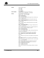
Preface
Scope and
Objectives
This manual is part of the documentation set for the CDA 7 family of products.
The CDA 7 is a very reliable high performance Integrated Cached Disk Array
(ICDA) designed for online data storage.
This manual describes CDA 7 maintenance and ORU replacement procedures.
Intended
Readers
This manual is intended for personnel involved in maintaining and repairing the
CDA 7 5330.
Versions of the Product
• For GCOS 7 systems, the CDA 7 5330 subsystem is available with two disk
technologies giving two different disk capacities: 9 GB and 18 GB.
9 GB refers to the formatted disk capacity. This is equivalent to an unformatted
disk capacity of 11.5 GB.
18 GB refers to the formatted disk capacity. This is equivalent to an unformatted
disk capacity of 23 GB.
This manual applies to both the 9 GB and 18 GB disk technologies. However, if
a section of text applies only to just one disk technology (9 GB or 18 GB), then
this is explicitly stated in the text. If no such indication is given, then the text
concerned applies to both the 9 GB and the 18 GB disks.
• CDA 7 5630 is available with 18 GB or 36 GB disk devices.
18 GB refers to the formatted disk capacity. This is equivalent to an unformatted
disk capacity of 23 GB.
36 GB refers to the formatted disk capacity. This is equivalent to an unformatted
disk capacity of 47 GB.
77 A7 48UU Rev03
iii
CDA 7 Maintenance Manual
Structure
iv
This manual is structured as follows:
Chapter 1
Introduction, provides a overview of the CDA 7
system.
Chapter 2
About the Lap-Top shows the place and connections
of the Lap-Top in the CDA 7 5330 subsystem.
Chapter 3
System Repairs, contains instructions for replacing
CDA 7 components.
Chapter 4
Part Catalog, provides a list of part numbers to be
used when ordering replacement parts for the CDA 7.
Chapter 5
Add-On/Microcode Upgrade, describes how to
perform add-ons to the CDA 7 subsystem.
Appendix A
Software Release and CDA 7 Configurations (9 GB
Disks). This describes how the software release is
identified and the outlines the possible CDA 7
subsystem configurations. Appendix A applies to
systems with 9 GB disks only.
Appendix B
Error Report (GCOS 7 PRLOG). This contains the
channel exeption messages and the information on the
cause of this state. Appendix B applies both to
systems with 9 GB disks and to systems with 18 GB
disks.
Appendix C
Installing the CDA 7 5330 With Microcode
Release 5263. Release 5263 of the Microcode can run
on systems only 9 GB disks only. Therefore,
Appendix C applies to systems with 9 GB disks only.
Appendix D
Software Release and CDA 7 Configurations
(18 GB Disks). This is the equivalent of Appendix A
except that Appendix D applies to systems with
18 GB disks only.
Appendix E
Installing the CDA 7 5330 With Microcode
Release 5264. Release 5264 of the Microcode can run
on systems with either 9 GB disks or 18 GB disks.
Appendix F
Installing the CDA 7 5630 With Microcode
Release 5265. Release 5265 of the Microcode can run
on systems with either 18 GB disks or 36 GB disks.
Glossary
Defines the terms used in this manual.
77 A7 48UU Rev03
Preface
Bibliography
The following manuals discuss related subjects:
Bull DPS 7000 User’s Guide Firmware Release Bulletin ........................77 A7 67US
Bull DPS 7000 - System Repair Manual ...................................................77 A7 72US
CDA/x Product Manual .............................................................................96 A1 70EC
CDA 7 Maintenance Manual...................................................................77 A7 48UU
CDA 7 5330 Site Preparation...................................................................77 A1 97UU
CDA 7 5330 Product Manual (9 GB)....................................................... 77 A1 61UP
CDA 7 5330-23 Product Manual (18 GB) ............................................... 77 A1 66UP
CDA 7 5630 Site Preparation................................................................... 77 A1 70UP
CDA 7 5630 Product Manual ................................................................... 77 A1 69UP
77 A7 48UU Rev03
v
CDA 7 Maintenance Manual
vi
77 A7 48UU Rev03
Table of Contents
1.
2.
3.
Introduction................................................................................................. 1-1
1.1
System Performance .................................................................................................. 1-1
1.2
Logical Architecture.................................................................................................... 1-5
1.3
POWER Subsystem ..................................................................................................1-22
1.3.1 Fan Assemblies............................................................................................1-23
1.3.2 Operator Panel .............................................................................................1-24
1.4
CDA 7 System Connection Example..........................................................................1-26
1.4.1 External Cable Requirements .......................................................................1-27
1.4.2 LABEL Command.........................................................................................1-28
1.4.3 Cable Requirements (View From MNCONF).................................................1-29
1.5
Installation Conditions ...............................................................................................1-29
About the Lap-Top ...................................................................................... 2-1
2.1
Location of the Lap-Top.............................................................................................. 2-1
2.2
Types of Lap-Top ....................................................................................................... 2-2
2.3
Verifying the Lap-Top Connections ............................................................................. 2-2
2.4
Connecting the Modem .............................................................................................. 2-4
System Repairs........................................................................................... 3-1
3.1
ORU Classes ............................................................................................................. 3-2
3.2
Power Down/power up Procedure .............................................................................. 3-3
3.2.1 Routine Power Down ..................................................................................... 3-3
3.2.2 Emergency Power Down ............................................................................... 3-3
3.2.3 Power On ...................................................................................................... 3-4
3.3
Non-disruptive Replacement of Components .............................................................. 3-4
3.3.1 Replacing a Disk-Drive .................................................................................. 3-5
77 A7 48UU Rev03
vii
CDA 7 Maintenance Manual
3.3.2
3.3.3
3.3.4
3.3.5
3.3.6
3.3.7
3.3.8
4.
5.
viii
Replacing the Director and Communication Card..........................................3-11
Replacing the DA#1 from the Lap-Top Access Change.................................3-13
Replacing the Memory Board........................................................................3-15
Replacing the Battery ...................................................................................3-16
Replacing a Fan Module ...............................................................................3-17
Replacing the Power Supply .........................................................................3-19
Replacing the Lap-Top .................................................................................3-21
3.4
Disruptive Replacement Procedures..........................................................................3-22
3.4.1 Replacing the Power Distribution Module......................................................3-22
3.4.2 Replacing the Adapter Card..........................................................................3-22
3.5
Alarm Codes and Errors ............................................................................................3-23
3.5.1 COM Card Alarm Code.................................................................................3-23
3.5.2 Director Alarm Codes ...................................................................................3-23
3.5.3 Environment Faults.......................................................................................3-24
3.5.4 Displaying the Memory Error Map.................................................................3-27
3.5.5 Displaying the Hardware Status Revision......................................................3-29
3.6
Log Files ...................................................................................................................3-31
3.6.1 Types of Log Files ........................................................................................3-31
3.6.2 Displaying the Log Files................................................................................3-32
3.6.3 Copying a Log File........................................................................................3-34
Parts Catalog............................................................................................... 4-1
4.1
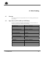
Overview.................................................................................................................... 4-1
4.2
Spare Parts List 5330 (9 GB and 18 GB Disks)........................................................... 4-1
4.3
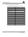
Spare Parts List 5630 (18 GB and 36 GB Disks)......................................................... 4-2
Add-On/Microcode Upgrade....................................................................... 5-1
5.1
DPS 7000 Add-on Hardware ...................................................................................... 5-2
5.1.1 Step 1 ........................................................................................................... 5-3
5.1.2 Step 2 ........................................................................................................... 5-4
5.1.3 Step 3 ........................................................................................................... 5-4
5.1.4 Step 4 ........................................................................................................... 5-5
5.2
Microcode Upgrade/Modification................................................................................. 5-5
77 A7 48UU Rev03
A.
B.
C.
Software Release and CDA 7 Configurations (9 GB Disks)......................A-1
A.1
Software Level ........................................................................................................... A-1
A.2
Bin Files ..................................................................................................................... A-2
A.3
CDA 7 5330 Disk Configurations ................................................................................ A-3
A.4
Basic Models.............................................................................................................. A-4
A.4.1 MSPD038-0000: 4 Mirror ............................................................................... A-4
A.4.2 MSPD039-0000: 8 Mirror ............................................................................... A-5
A.4.3 MSPD040-0000: 12 Mirror ............................................................................. A-6
A.4.4 MSPD041-0000: 16 Mirror ............................................................................. A-7
A.4.5 MSPD042-0000: 6 RAID-S ............................................................................ A-8
A.4.6 MSPD039-0000: 9 RAID-S ............................................................................ A-9
A.4.7 MSPD040-0000: 12 RAID-S ........................................................................ A-10
A.4.8 MSPD041-0000: 15 RAID-S ........................................................................ A-11
A.4.9 MSPD042-0000: 18 RAID-S ........................................................................ A-12
A.4.10 MSPD043-0000: 21 RAID-S ........................................................................ A-13
A.4.11 MSPD044-0000: 24 RAID-S ........................................................................ A-14
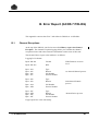
Error Report (GCOS 7 PRLOG) ..................................................................B-1
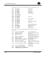
B.1
Channel Exceptions ................................................................................................... B-1
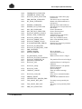
B.2
I/O Errors ................................................................................................................... B-5
B.3
Disk PSB/DSB Termination Report ............................................................................. B-5
Installing the CDA 7 5330 with Microcode Release 5263 ..........................C-1
C.1
Before Installation....................................................................................................... C-1
C.2
Installation Conditions/Auxiliaries................................................................................ C-2
C.3
Installing the CDA 7 on a Host System ....................................................................... C-3
C.3.1 Unpacking the CDA 7 .................................................................................... C-3
C.3.2 Powering Up the CDA 7................................................................................. C-5
C.3.3 Setting the CDA 7 Internal Clocks.................................................................. C-6
C.3.4 Setting the Site Information............................................................................ C-8
C.3.5 Verifying the Site Information ....................................................................... C-12
C.3.6 Setting the Modem Parameters ................................................................... C-14
C.3.7 Verifying the CDA 7 Configuration ............................................................... C-15
C.3.8 Declaring the CDA 7 Subsystem under GCOS 7.......................................... C-30
77 A7 48UU Rev03
ix
CDA 7 Maintenance Manual
D.
E.
F.
x
Software Release and CDA 7 Configurations (18 GB Disks)...................D-1
D.1
Software Level ........................................................................................................... D-1
D.2
BIN Files .................................................................................................................... D-2
D.3
CDA 7 5330 Disk Configurations ................................................................................ D-3
D.4
Basic Models.............................................................................................................. D-4
D.4.1 Binary File S01-200.BIN ................................................................................ D-4
D.4.2 Binary File S02-200.BIN ................................................................................ D-5
D.4.3 Binary File S03-200.BIN ................................................................................ D-6
D.4.4 Binary File S04-200.BIN ................................................................................ D-7
D.4.5 Binary File S05-200.BIN ................................................................................ D-8
D.4.6 Binary File S06-200.BIN ................................................................................ D-9
D.4.7 Binary File S07-200.BIN .............................................................................. D-10
D.4.8 Binary File S08-200.BIN .............................................................................. D-11
Installing the CDA 7 5330 with Microcode Release 5264 .......................... E-1
E.1
Before Installation....................................................................................................... E-1
E.2
Installation Conditions/auxiliaries ................................................................................ E-2
E.3
Installing the CDA 7 on a Host System ....................................................................... E-3
E.3.1 Unpacking the CDA 7 .................................................................................... E-3
E.3.2 Powering Up the CDA 7................................................................................. E-5
E.3.3 Setting the PC Parameters ............................................................................ E-6
E.3.4 Setting the Site Information............................................................................ E-8
E.3.5 Verifying the Site Information ....................................................................... E-13
E.3.6 Setting the Modem Parameters ................................................................... E-15
E.3.7 Verifying the CDA 7 Configuration ............................................................... E-17
E.3.8 Declaring the CDA 7 Subsystem under GCOS 7.......................................... E-34
Installing the CDA 7 5630 with Microcode Release 5265 .......................... F-1
F.1
Before Installation....................................................................................................... F-1
F.2
Installation Conditions/auxiliaries ................................................................................ F-2
F.3
Installing the CDA 7 on a Host System ....................................................................... F-3
F.3.1 Unpacking the CDA 7 .................................................................................... F-3
F.3.2 Powering Up the CDA 7................................................................................. F-5
F.3.3 Setting the PC Parameters ............................................................................ F-6
F.3.4 Setting the Site Information............................................................................ F-8
F.3.5 Verifying the Site Information ....................................................................... F-13
77 A7 48UU Rev03
F.3.6
F.3.7
F.3.8
Setting the Modem Parameters ................................................................... F-16
Verifying the CDA 7 Configuration ............................................................... F-18
Declaring the CDA 7 Subsystem under GCOS 7.......................................... F-30
Glossary ............................................................................................................. g-1
Index .................................................................................................................... i-1
77 A7 48UU Rev03
xi
CDA 7 Maintenance Manual
Table of Graphics
Figures
1-1.
1-2.
1-3.
1-4.
1-5.
1-6.
1-7.
1-8.
1-9.
1-10.
1-11.
1-12.
1-13.
1-14.
1-15.
1-16.
1-17.
1-18.
1-19.
1-20.
1-21.
1-22.
1-23.
1-24.
1-25.
1-26.
1-27.
1-28.
2-1.
2-2.
2-3.
3-1.
3-2.
3-3.
3-4.
3-5.
xii
CDA 7 Subsystem ..................................................................................................... 1-1
CDA 7 (Rear View - 9 GB).......................................................................................... 1-2
CDA 7 (Rear View - 18 GB and 36 GB) ...................................................................... 1-3
CDA 7 Main Components (Exploded View)................................................................. 1-4
Interconnection of Main Components.......................................................................... 1-6
CDA 7 Front View (Covers Off)................................................................................... 1-7
Disk Director Device (Front View) ............................................................................... 1-8
Disk Device Director (Rear View)................................................................................ 1-9
Front Card Cage (Location of Channel Director) ........................................................1-10
Dual Processor Directors...........................................................................................1-11
Memory Board (Close Up) .........................................................................................1-12
CDA 7 Rear View (Covers Off) - 9 GB Disks..............................................................1-13
CDA 7 Rear View (Covers Off) - 18 GB Disks............................................................1-14
Rear Card Cage (Location of SCSI Adapters)............................................................1-15
SCSI Adapter Switch Positions ..................................................................................1-16
SCSI Cable Connection.............................................................................................1-17
SCSI Adapter Locations and Port Assignments .........................................................1-18
Location of COM Card...............................................................................................1-19
COM Card - 2 Types .................................................................................................1-20
3.5 inch. Disk-Drives..................................................................................................1-21
CDA 7 Power Subsystem ..........................................................................................1-22
Fan Assemblies.........................................................................................................1-23
Operator Panel - 9 GB...............................................................................................1-24
Operator Panel - 18 GB .............................................................................................1-25
System Connection Example (Configurations) ...........................................................1-26
CDA 7 External Cable Requirements.........................................................................1-27
CDA 7 Connections...................................................................................................1-28
Cable Requirements (View From MNCONF)..............................................................1-29
CDA 7 and its Lap-Top ............................................................................................... 2-1
Lap-Top Connections ................................................................................................. 2-2
Cover of the Modem Plug ........................................................................................... 2-4
Marking the Mirror Disk-Drive 1000 ............................................................................ 3-7
Director and COM Card Replacement Procedure ......................................................3-11
Unmounting Lateral Panel .........................................................................................3-16
Location of Fan Modules ...........................................................................................3-17
Unmounting Fan Modules..........................................................................................3-18
77 A7 48UU Rev03
3-6.
3-7.
3-8.
3-9.
3-10.
3-11.
5-1.
C-1.
C-2.
C-3.
C-4.
C-5.
C-6.
C-7.
C-8.
C-9.
C-10.
C-11.
C-12.
C-13.
C-14.
C-15.
C-16.
C-17.
C-18.
C-19.
E-1.
E-2.
E-3.
E-4.
E-5.
E-6.
E-7.
E-8.
E-9.
E-10.
E-11.
E-12.
E-13.
E-14.
E-15.
E-16.
E-17.
E-18.
E-19.
E-20.
F-1.
F-2.
F-3.
F-4.
F-5.
Battery With Extension ..............................................................................................3-19
Power Supply (Rear View).........................................................................................3-20
Lap-Top in the Front Door .........................................................................................3-21
Power Distribution Module.........................................................................................3-22
Alarm Codes .............................................................................................................3-23
Environment Fault Display.........................................................................................3-26
Add-On Procedure Overview ...................................................................................... 5-2
CDA 7 5330, Removing the Shipping Brackets ........................................................... C-4
Symm4 Main Window................................................................................................. C-7
Site Information - 1 ..................................................................................................... C-8
Site Information - 2 ..................................................................................................... C-8
Site Information - 3 ..................................................................................................... C-9
Site Information - 4 ................................................................................................... C-10
Site Information - 5 ................................................................................................... C-10
Customer Name ....................................................................................................... C-12
Cabinet Serial Number ............................................................................................. C-13
Modem Parameter Setting........................................................................................ C-14
Checking the Configuration ...................................................................................... C-17
The Automatic Install Command ............................................................................... C-21
Automatic Install Screens ......................................................................................... C-22
Warning before a Disk-Device Format ...................................................................... C-22
Installation Dialog ..................................................................................................... C-23
The Change Command - 1 ....................................................................................... C-24
The Change Command - 2 ....................................................................................... C-25
The Change Command - 3 ....................................................................................... C-26
Distribution of Logical Units ...................................................................................... C-27
CDA 7 5330, Removing the Shipping Brackets ........................................................... E-4
PC Configuration - 1 ................................................................................................... E-6
PC Configuration - 2 ................................................................................................... E-7
Site Information - 1 ..................................................................................................... E-8
Site Information - 2 ..................................................................................................... E-9
Site Information - 3 ................................................................................................... E-10
Site Information - 4 ................................................................................................... E-11
Site Information - 5 ................................................................................................... E-11
Customer Name ....................................................................................................... E-13
Cabinet Serial Number ............................................................................................. E-14
Modem Parameter Setting........................................................................................ E-15
Checking the Configuration ...................................................................................... E-19
The Automatic Install Command ............................................................................... E-23
Automatic Install Screens ......................................................................................... E-24
Current Configuration ............................................................................................... E-25
Installation Dialog (1/3)............................................................................................. E-26
The Change Command - 1 ....................................................................................... E-28
The Change Command - 2 ....................................................................................... E-29
The Change Command - 3 ....................................................................................... E-30
Distribution of Logical Units ...................................................................................... E-31
CDA 7 5630, Removing the Shipping Brackets ........................................................... F-4
PC Configuration - 1 ................................................................................................... F-6
PC Configuration - 2 ................................................................................................... F-7
Site Information - 1 ..................................................................................................... F-8
Site Information - 2 ..................................................................................................... F-9
77 A7 48UU Rev03
xiii
CDA 7 Maintenance Manual
F-6.
F-7.
F-8.
F-9.
F-10.
F-11.
F-13.
F-14.
F-15.
F-16.
F-17.
F-18.
F-19.
F-20.
Site Information - 3 ................................................................................................... F-10
Site Information - 4 ................................................................................................... F-11
Site Information - 5 ................................................................................................... F-11
Customer Name ....................................................................................................... F-13
Cabinet Serial Number ............................................................................................. F-15
Modem Parameter Setting........................................................................................ F-16
The Automatic Install Command ............................................................................... F-19
Automatic Install Screens ......................................................................................... F-20
Current Configuration ............................................................................................... F-21
Installation Dialog (1/3)............................................................................................. F-22
The Change Command - 1 ....................................................................................... F-24
The Change Command - 2 ....................................................................................... F-25
The Change Command - 3 ....................................................................................... F-26
Distribution of Logical Units ...................................................................................... F-27
Tables
3-1.
xiv
ORU Classes ............................................................................................................. 3-2
77 A7 48UU Rev03
1. Introduction
This chapter provides an overview of the CDA 7 Integrated Cache Disk Array
(ICDA) highlighting its performance and reliability features.
1.1
System Performance
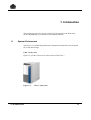
The CDA 7 is a reliable high performance Integrated Cached Disk Array designed
for on-line data storage.
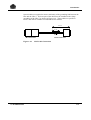
CDA 7 (front view)
Figure 1-1 provides a front view of the exterior of the CDA 7.
Figure 1-1.
77 A7 48UU Rev03
CDA 7 Subsystem
1-1
CDA 7 Maintenance Manual
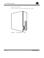
CDA 7 (rear view) - 9 GB
Figure 1-2 provides a rear view of the exterior of the CDA 7 (9 GB).
I I
E
P
O
0 0
Figure 1-2.
1-2
A
C
I
N
CDA 7 (Rear View - 9 GB)
77 A7 48UU Rev03
Introduction
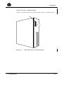
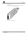
CDA 7 (rear view) - 18 GB and 36 GB
Figure 1-3 provides a rear view of the exterior of the CDA 7 (18 GB and 36 GB).
EPO
I I
0 0
Figure 1-3.
77 A7 48UU Rev03
AC IN
CDA 7 (Rear View - 18 GB and 36 GB)
1-3
CDA 7 Maintenance Manual
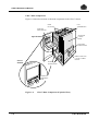
CDA 7 Main Components
Figure 1-4 shows the location of the main components in the CDA 7 chassis.
DISK
DEVICES
FAN
ASSEMBLIES
SERVICE
PROCESSOR
ADAPTER
CARDS
REAR
Open Position
BATTERY
SUBSYSTEM
DIRECTOR AND
CACHE CARDS
FRONT
Closed
Position
POWER
SUBSYSTEM
INTERNAL
ETHERNET
HUB
Figure 1-4.
1-4
CDA 7 Main Components (Exploded View)
77 A7 48UU Rev03
Introduction
1.2
Logical Architecture
Links to the system are established with a Fast-Wide / Ultra SCSI type interface.
Director channels and adapter channels are specific to the SCSI interface of the
DPS 7000.
1
3
3
IMPORTANT:
The abbreviations used in this document are:
77 A7 48UU Rev03
1.
Channel Director = SD (SCSI Director)
2.
Channel Adapter = SA (SCSI Adapter for the link with the WSP board).
1-5
CDA 7 Maintenance Manual
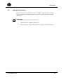
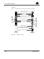
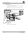
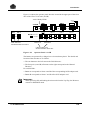
Interconnection of Main Components
Figure 1-5 shows the interconnection of the main components of the CDA 7.
Main AC
Power Dist.
Module
Main switches
EPO
POWER Distribution
Module (PDM)
50 V
DC
PS1
EPO
Modem
Power
Supply
FANS
PS2
56V, 24V 56V, 24V
12V, 5V 12V, 5V
BATTERY
BACKUP
MODEM
PC Power
Supply
HUB
ETHERNET
LAPTOP PC
24 V
DC
RS232
Parallel
12 V DC
Operator Panel
Mem
24 V DC
Mem
SA
SA
SA
SA
SD
SD
SD
SD
X bus
Y bus
DA
Figure 1-5.
1-6
DA
Interconnection of Main Components
77 A7 48UU Rev03
Introduction
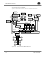
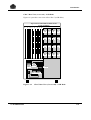
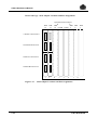
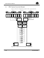
CDA 7 Front View (covers off)
Top Cover is removable to
allow access to fan assemblies
DIR-2b DIR-2b DIR-2b DIR-2b
C0
C1
C2
C3
DIR-2b DIR-2b DIR-2b DIR-2b
D1
D2
D4
D0
DIR-2a DIR-2a DIR-2a DIR-2a
C0
C1
C2
C3
DIR-2b DIR-2b DIR-2b DIR-2b
D0
D1
D2
D3
JL1 5V blue
JL2 5V red
JL3 12V blue
JL4 12V red
JL5 24V blue
JL6 24V red
ADJ ADJ ADJ
5V 12V 24V
123456
PS1
123
JL1 5V
JL2 12V
JL3 24V
JL1
JL2
JL3
JL4
JL5
JL6
Modem Plug
Figure 1-6.
77 A7 48UU Rev03
5V blue
5V red
12V blue
12V red
24V blue
24V red
ADJ ADJ ADJ
5V 12V 24V
123456
PS2
123
JL1 5V
JL2 12V
JL3 24V
CDA 7 Front View (Covers Off)
1-7
CDA 7 Maintenance Manual
Disk Director Device
Figures 1-7 and 1-8 provide a front and rear view of the disk director device.
Front View
DIR 02, slot 1
#0 #1
#2
#3
SCSI C
Bus C
SCSI D
Processor B
Bus D
SCSI C
Bus C
SCSI D
Bus D
Example:
Processor A
SCSI D,
Address #3
Figure 1-7.
1-8
Disk Director Device (Front View)
77 A7 48UU Rev03
Introduction
Rear View
DIR 01, slot 0
(Rear view)
#0
#1
SCSI C
Processor B
#2
#3
Example:
SCSI D,
Address #3
SCSI D
SCSI C
Processor A
SCSI D
Figure 1-8.
77 A7 48UU Rev03
Disk Device Director (Rear View)
1-9
CDA 7 Maintenance Manual
Front Card Cage - Channel Director Location
Figure 1-9 shows the location of the channel directors in the CDA 7.
SCSI
Channel Directors
Disk Directors
Slot
DIR
0
1
Figure 1-9.
1-10
1
2
SCSI
Channel Directors
Memory
2
3
3
M
c
M
d
14
e
15
f
16
Front Card Cage (Location of Channel Director)
77 A7 48UU Rev03
Introduction
Dual Processor Director
Figure 1-10 provides a close-up view of a dual processor director.
Right side view
(Floor)
Screw
Ejector tab
Hard Reset
Push button
Display
(OF = Off Line)
E
D
C
B
A
Rotary
switches
Power for
external tests
RS232
(Engineering)
Yellow led
Attention
button
Director
Enable/Disable
(Down = Enable)
Green led
E
D
C
B
A
F 0 1
9 8 7
F 0 1
9 8 7
2
3
4
5
6
2
3
4
5
6
B -Processor
A -Processor
Display
(OF = Off Line)
RS232
(Engineering)
Yellow led
Attention
button
Green led
Ejector tab
Screw
Figure 1-10.
77 A7 48UU Rev03
Dual Processor Directors
1-11
CDA 7 Maintenance Manual
Front Card Cage - Memory Board Location
Refer to the Front Card Cage figure above to locate the memory boards in the
CDA 7.
Memory Board
Figure 1-11 provides a close-up view of a memory board.
Ejector tab
Hardware Reset
Yellow LED
(X-Bus error)
Green LED - (Cache active)
Green LED - (X-Bus active)
SW2 X-Bus - (Up=Enable - Down=Disable)
Yellow LED
(Y-Bus error)
Green LED - (Y-Bus active)
SW2 Y-Bus - (Up=Enable - Down=Disable)
Power for
External test
Ejector tab
Figure 1-11.
1-12
Memory Board (Close Up)
77 A7 48UU Rev03
Introduction
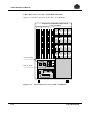
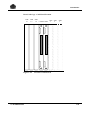
CDA 7 Rear View (covers off) - 9 GB Disks
Figure 1-12 provides a rear view of the CDA 7 (9 GB disks).
Top Cover is removable to allow access
to fan assemblies
f
e
d c
3
2 1 0
DIR-1b DIR-1b DIR-1b DIR-1b
C0
C1
C2
C3
DIR-1b DIR-1b DIR-1b DIR-1b
D0
D1
D2
D3
DIR-1a DIR-1a DIR-1a DIR-1a
C0
C1
C2
C3
DIR-1a DIR-1a DIR-1a DIR-1a
D0
D1
D2
D3
PS1 PS2
EPO
Switch
AC
Switch
AC Input
DC to Battery
Figure 1-12.
77 A7 48UU Rev03
CDA 7 Rear View (Covers Off) - 9 GB Disks
1-13
CDA 7 Maintenance Manual
CDA 7 Rear View (covers off) - 18 GB Disks and 36GB
Figure 1-13 provides a rear view of the CDA 7 (18 GB Disks).
Top Cover is removable to allow access
to fan assemblies
f
e
d c
3
2 1
0
DIR-1b DIR-1b DIR-1b DIR-1b
C0
C1
C2
C3
DIR-1b DIR-1b DIR-1b DIR-1b
D0
D1
D2
D3
DIR-1a DIR-1a DIR-1a DIR-1a
C0
C1
C2
C3
DIR-1a DIR-1a DIR-1a DIR-1a
D0
D1
D2
D3
Switches On/Off
PS1
PS2
Dual AC Input
PS1
PS2
DC to Battery
Figure 1-13.
1-14
CDA 7 Rear View (Covers Off) - 18 GB Disks
77 A7 48UU Rev03
Introduction
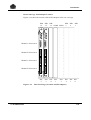
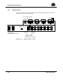
Rear Card Cage -SCSI Adapter Location
Figures 1-14 shows the location of the SCSI Adapters in the rear card cage.
DIR
16
DIR
15
DIR
DIR
14 COM0 COM1 3
DIR
2
DIR
1
Slot
f
Slot
e
Slot
d
Slot Slot
1
0
Channel A Processor b
Channel B Processor b
Channel A Processor a
Channel B Processor a
Figure 1-14.
77 A7 48UU Rev03
Slot
c
Slot
3
Slot
2
Rear Card Cage (Location of SCSI Adapters)
1-15
CDA 7 Maintenance Manual
Rear Card Cage - SCSI Adapter Switch Positions
Figures 1-14 shows the SCSI Adapter switch positions in the rear card cage.
FUSES
TERMPOWER
SCSI C
SWC2
ENABLE
VCC
SWC1
DISABLE
LED
TERMPOWER
SCSI D
SWD2
ENABLE
SWD1
VCC
DISABLE
LED
TERMPOWER
SWE2
SCSI E
VCC
ENABLE
SWE1
DISABLE
LED
TERMPOWER
SCSI F
SWF2
VCC
ENABLE
SWF1
DISABLE
LED
Figure 1-15.
1-16
FUSES
SCSI Adapter Switch Positions
77 A7 48UU Rev03
Introduction
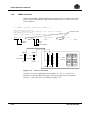
Special cables are required to ensure conformity of the grounding link between the
host and the CDA 7. The bare part of the cable must be installed in the clamp
grounding of the CDA 7 as shown in Figure 1-16. These cables are specific to
CDA 7 and will be available for refurbished 5100 models.
90 cm
5 cm
Shield
Host Interface
Figure 1-16.
77 A7 48UU Rev03
CDA 7 Interface
SCSI Cable Connection
1-17
CDA 7 Maintenance Manual
Rear Card Cage - SCSI Adapter Locations and Port Assignments
Optional SCSI Locations
DIR
16
DIR
15
DIR
DIR
14 COM0 COM1 3
e
d
DIR
2
DIR
1
Channel A Processor b
Channel B Processor b
Channel A Processor a
Channel B Processor a
f
Figure 1-17.
1-18
c
3
2
1
0
SCSI Adapter Locations and Port Assignments
77 A7 48UU Rev03
Introduction
Rear Card Cage - COM Card Location
DIR
16
DIR
15
Figure 1-18.
77 A7 48UU Rev03
DIR
DIR
14 COM0COM1 3
DIR
2
DIR
1
Location of COM Card
1-19
CDA 7 Maintenance Manual
COM Card
Figure 1-19, below, provides a close-up view of two types of COM cards.
3 positions slider switch
(Must be in low position)
Jumper J1
RS232 connector, (Engeenering)
Remote power connector
CR4
CR19
CR15
CR17
CR11
CR10
CR18
CR16
SW5 Attention switch
CR4
CR19
CR15
CR17
CR11
CR10
CR18
CR16
SW6 Enable/Disable switch
(8) Green LED’s (8)
(2) Yellow LED’s (7)
CR9
CR22
CR9
CR20
CR23
CR24
C25
CR26
CR22
Rotary switches
(Must be in "00" position)
SW4 Enable/Disable (Hot replacement)
(Up = Disable / Down = Enable)
Hexadecimal display
COM card
type "028"
Figure 1-19.
1-20
COM card
type "692"
COM Card - 2 Types
77 A7 48UU Rev03
Introduction
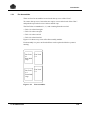
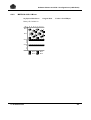
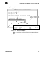
3.5 inch. Disk-Drives
The CDA 7 uses 3.5" disk-drives with a formatted capacity of 9 or 18 GBytes. 18
Gbyte devices are split into two logical 9 Gbyte drives.
Figure 1-20.
77 A7 48UU Rev03
3.5 inch. Disk-Drives
1-21
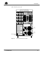
CDA 7 Maintenance Manual
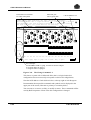
1.3
POWER Subsystem
The CDA 7 power subsystem provides a redundant source of DC power to the
major components in the CDA 7 cabinet.
Figure 1-21 provides an overview of the EPO assembly and power supplies
above it.
8
7
6
5
4
3
3.5 DISK CAGE
DRIVE CAGE FRONT
F1
2
1
POWER
BUSS
BARS 3.5 DISK CAGE
+24V
F2
CARD CAGE
BACKPLANE
24VRTN
DRIVE CAGE REAR
F1
PAN
TACHS
+24V
F2
PARALLEL PORT CABLE
24VRTN
RS232 CABLE
DRIVE CAGE FRONT
F1
F2
F3
F4
POWER SUPPLY STATUS
/ CONTROL CABLE
+24V
24VRTN
DRIVE CAGE REAR
PS#1
F1
F2
F3
F4
+24V
+ + +
5V 12V 24V
-
24VRTN
AC PH1
AC PH2
GND
PS#2
EPO BOX
RED SW BLK SW
BAT
+ + + STATUS
5V 12V 24V CONN
AC PH1AC PH2
GND
AC MAIN
INPUT
STATUS
CONN
-
-
BAT
+
-
DC/DC
CONV
12 VOLTS
BATTERY BOX
- +
BAT4
- +
BAT3
- +
BAT2
- +
BAT1
In the case of 9 GB disks,
the 2nd power supply is optional.
Figure 1-21.
1-22
CDA 7 Power Subsystem
77 A7 48UU Rev03
Introduction
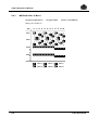
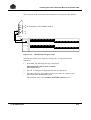
1.3.1
Fan Assemblies
There are four fan assemblies located under the top cover of the CDA 7.
To remove the top cover, loosen the two captive screws in the back of the CDA 7
and push the top back one to two inches and lift it up.
The Fan Tachs are numbered 1, 2 ,3 and 4 starting from the rear left:
• Tach 3 is at the front right.
• Tach 2 is at the rear right.
• Tach 1 is at the rear left.
• Tach 4 is at the front left.
Figure 1-22 shows a top view of the fan assembly module.
Each assembly is a press-on fit and all fans can be replaced while the system is
running.
Fan Tach
#1
Rear Disk
Cage
Fan Tach
#4
Front Disk
Cage
Figure 1-22.
77 A7 48UU Rev03
Fan Tach
#2
Fan Tach
#3
Fan Assemblies
1-23
CDA 7 Maintenance Manual
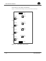
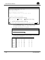
1.3.2
Operator Panel
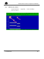
Figure 1-23 shows the operator panel which is located in the upper part of the front
door of the CDA 7 5330 unit (9 GB).
Active/Ready LEDS
DIR3
POWER
A
B
DA 1
Re a dy
Active
CA
DB
DA 2
C A
D B
DIR 14
EN
RESET
DIR16
DIR15
DIR14
C A
D B
DIR 15
C
D
DIR 16
ENABLE
DISABLE
DIS
Disk Director
Enable/Disable Switches
Button A
Button B
Channel Director
Enable/Disable Switches
Figure 1-23.
1-24
Operator Panel - 9 GB
77 A7 48UU Rev03
Introduction
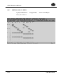
Figure 1-24 shows the operator panel which is located in the upper part of the front
door of the CDA 7 5330 unit (18 GB).
Active/Ready LEDS
DIR3
POWER
A
B
DA 1
Ready
Active
DA 2
BA
b a
B A
b a
DIR 14
EN
RESET
DIR16
DIR15
DIR14
B A
b a
DIR 15
B
b
DIR 16
ENABLE
DISABLE
DIS
Disk Director
Enable/Disable Switches
Button A
Button B
Channel Director
Enable/Disable Switches
Figure 1-24.
Operator Panel - 18 GB
The buttons are protected by a hinged cover in translucent plastic. The details and
location of the switches are as follows:
• The two buttons to the left concern the Disk Directors.
• The four pairs (A and B) of buttons on the right correspond to the Channel
Directors.
For an SCSI link:
• Button A corresponds to Ports A and B of the corresponding SCSI Adapter card.
• Button B corresponds to Ports C and D of the SCSI Adapter card.
1
3
3
IMPORTANT:
When powering ON and loading the microcode from the Lap-Top, the Directors
must be in DISABLE mode.
77 A7 48UU Rev03
1-25
CDA 7 Maintenance Manual
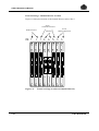
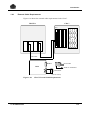
1.4
CDA 7 System Connection Example
Figure 1-25 shows the configurations possible for CDA 7 system connection.
MB2-04
GRP 0-0
19
18
17
GRP 0-3
16
15
WSP WSP
0-1
MB2-05
(DPS 7000)
14
13
GRP 0-1
12
08
07
WSP WSP
0-1
0-1
D
05
04
WSP WSP
0-1
A
B
C
06
GRP 0-2
0-1
ESDS
CHANNEL
DIRECTOR
1
CHANNEL
DIRECTOR
2
DIRECTORY
DIRECTORY
CACHE
CACHE
DISK
DIRECTOR
1
03
02
01
WSP WSP
0-1
0-1
0-1
A
B
C
D
DISK
DIRECTOR
2
DISK
DISK
DISK
DISK
DISK
DISK
DISK
A
B
C
D
DISK
CHANNEL
DIRECTOR
3
Figure 1-25.
1-26
CHANNEL
DIRECTOR
4
A
B
C
D
System Connection Example (Configurations)
77 A7 48UU Rev03
Introduction
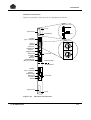
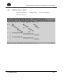
1.4.1
External Cable Requirements
Figure 1-26 shows the external cable requirements for the CDA 7.
HOST#1
CDA 7
SA
Disks
SCSI cable
Port 0
SCSI cable
WSP
"built-in" terminator
Terminator
Port 1 (Never used !)
Figure 1-26.
77 A7 48UU Rev03
CDA 7 External Cable Requirements
1-27
CDA 7 Maintenance Manual
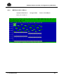
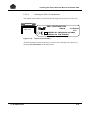
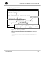
1.4.2
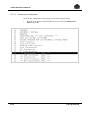
LABEL Command
Entering the LABEL command displays the connections file as shown in the figure
below. For more information, refer to the Bull DPS 7000 User’s Guide Firmware
Release Bulletin.
*** LABELs and CDA7 connections: MYCDA
Iom WSP-R slot 15
port 0 connected
Iom WSP-R slot 04
port 0 connected
*MB2-0-15-2
*
*
*
PX43
to Scsi Adaptor slot f port A cda #01
PX14
to Scsi Adaptor slot e port A cda #01
*MC01 SA f-A
*MS01
Slot #
MB2 #
MB2-0
***
*
*
*MB2-1-04-2
*MS02
*
*
*MC21 SA e-A
*MS03
*
*MS04
Port
Slot
SCSI Adapter
MB2-1
Port 0
Port 0
C
C
C
Terminator
Terminator
D
D
D
A
A
A
B
B
B
Slot 15
Controller name
Slot 04
Slot f
Figure 1-27.
CDA
cabinet
MS01
MS02
MS03
MS04
Slot e
CDA 7 Connections
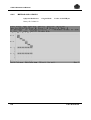
In Figure 1-27 (lower right hand side), the letters "A", "B", "C", and "D" are
references used by the MNCONF utility. Their meanings in terms of: Channel
Director <-> Processor pairs, are defined in Figure 1-28.
1-28
77 A7 48UU Rev03
Introduction
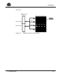
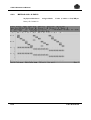
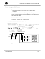
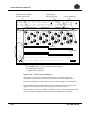
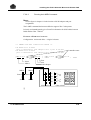
1.4.3
Cable Requirements (View From MNCONF)
Figure 1-28 shows the cable requirements for the CDA 7.
SCSI’s
SA-03A
B
C
D
SA-14A
B
C
D
20 21 22 23 24 25 26 27 . . . . . . . .
. . . . . . . . 20 21 22 23 24 25 26 27
. . . . . . . . . . . . . . . .
. . . . . . . . . . . . . . . .
20 21 22 23 24 25 26 27 . . . . . . . .
. . . . . . . . 20 21 22 23 24 25 26 27
. . . . . . . . . . . . . . . .
. . . . . . . . . . . . . . . .
Half Channel Director with B Processor
C
D
A
B
bA
bB
Half Channel Director with A Processor
aA
aB
Port Name
Figure 1-28.
1.5
Cable Requirements (View From MNCONF)
Installation Conditions
Fore more information about installation conditions, refer to:
• Appendix C, Installing the CDA 7 5330 With Microcode Release 5263, or
• Appendix E, Installing the CDA 7 5330 With Microcode Release 5264, or
• Appendix F, Installing the CDA 7 5630 With Microcode Release 5265, or
• the CDA 7 5330 Site Preparation Guide,
• the CDA 7 5630 Site Preparation Guide.
77 A7 48UU Rev03
1-29
CDA 7 Maintenance Manual
❑
1-30
77 A7 48UU Rev03
2. About the Lap-Top
2.1
Location of the Lap-Top
The Lap-Top for the CDA 7 is a TwinHead PC model used as a Service Processor.
It is located in the front door of the subsystem. The following figure shows the
position of the Lap-Top in the front door of the CDA 7.
Figure 2-1.
77 A7 48UU Rev03
CDA 7 and its Lap-Top
2-1
CDA 7 Maintenance Manual
2.2
Types of Lap-Top
There are two types of Lap-Top:
• the TwinHead 5 (090-000-039)
• the TwinHead 9 (090-000-040)
2.3
Verifying the Lap-Top Connections
The CDA 7 is delivered with an integral Lap-Top. The following figure shows the
connection that must be in place. In case of problems, refer to this figure and
verify that all the cables are in the right position.
To the HUB Ethernet
Parallel Port
RS232 Port
Power Cable
Verify the position Connection
Board
of the two plugs
Lap-Top
TwinHead
To the Bulkhead
and Modem
Figure 2-2.
1
3
3
Lap-Top Connections
IMPORTANT:
When connecting the TwinHead Lap-Top, verify that the Ethernet and the
Modem cables present the arrow on each plug as shown in Figure 2-2.
2-2
77 A7 48UU Rev03
About the Lap-Top
When you define the setup parameters of your Lap-Top, you need to enter the type
of the interface board. To find out the type, proceed as follows:
1.
Unplug the Modem and Ethernet cables.
2.
To extract the board, press on the lock and remove the board.
3.
Read the socket identifier on the board. The two possible values are:
− Socket I/O
− Silicom
For more information, refer to either: Appendix C, Installing the CDA 7 5330
With Microcode Release 5263, Appendix E Installing the CDA 7 5330 With
Microcode Release 5264 (depending on your Microcode release) or Appendix
F Installing the CDA 7 5630 With Microcode Release 5265.
4.
77 A7 48UU Rev03
Enter the parameter value in the corresponding field.
2-3
CDA 7 Maintenance Manual
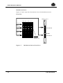
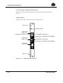
2.4
Connecting the Modem
Use a modem in the standard of the country where the CDA 7 is to be installed.
The COM card connector dedicated to the modem is at the end of a cable and is
accessible at the Bus & Tag BULKHEAD on the front, by means of internal
cabling:
1.
To locate the cables and connectors, refer to the figure Lap-Top Connections
above.
2.
The two cables on the left of the Lap-top have an arrow on the upper side of
the connectors. Connect the Hub Ethernet and the Modem cables as shown on
the figure (the arrow is on the outside part of the connectors).
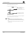
3.
Remove the RFI shielding that protects the access of the connectors in the
lower part of the CDA 7 subsystem. To do this, unscrew the two screws as
shown in the following figure:
CDA 7 Subsystem
Front View
Screws
RFI Shielding
Figure 2-3.
4.
2-4
Cover of the Modem Plug
Connect the cable to the connector, and put the RFI shielding in place. You
can put the modem on this shielding in the front part of the subsystem.
77 A7 48UU Rev03
3. System Repairs
This chapter contains only a broad outline of the procedures for removing and
replacing CDA 7 components. The replacement procedure used depends on the
category to which the component in question belongs. For full details of the
procedures, refer to the SYMMETRIX Maintenance Manual Part Number
PN-200-858-551, and in all cases contact your Bull Competence Center.
77 A7 48UU Rev03
3-1
CDA 7 Maintenance Manual
3.1
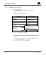
ORU Classes
There are two classes for ORU replacement:
• Class A, "non-disruptive procedure": Those that can be removed and replaced
while the system remains on-line.
• Class B, "disruptive procedure": Those that must be removed and replaced
off-line.
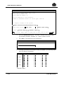
Table 3-1.
ORU Classes
Class A
Not PC Menu Driven
DISK DIRECTOR
Channel DIRECTOR
Memory Card
Adapter Card
Disk-drive
COM Card
Power Supply
PDM
Battery
LAP-TOP
Fan Unit
Microcode
Operator Panel
Class A
PC Menu Driven
X
X
Class B
X
X
X
X
X
X
X
X
X
X
X
X
NOTE:
ORUs replaced with the assistance of a PC Lap-Top are distinguished from
other ORUs. A number of components do not appear in this table since they are
obviously replaced off-line.
3-2
77 A7 48UU Rev03
System Repairs
3.2
Power Down/power up Procedure
This procedure describes the steps for powering down and powering up the CDA 7.
There are two procedures for powering down:
• routine
• emergency
3.2.1
Routine Power Down
To power down your CDA 7 subsystem:
3.2.2
1.
From your GCOS console, set the channels off-line. To do this, use the
TSYS 1 and HOLD MC commands.
2.
TS All (under SPV).
3.
Verify that all information in the cache has been "destaged".
4.
Switch the Directors to Disable status on the operator panel.
5.
Set the AC POWER SWITCH on the Power Distribution Module to the down
position and wait for the cooling fans to stop.
6.
In any circumstances, do not touch the EPO SWITCH.
7.
Turn the battery OFF.
Emergency Power Down
In case of emergency power down:
1.
Turn the EPO switch OFF. The AC power switch will drop automatically and
the cooling fans will stop after approximately 20 seconds.
2.
Before powering up the CDA 7, call the Bull Competence Center.
CAUTION:
Restarting after an Emergency Power Down must be done only after contacting
the Bull Competence Center.
77 A7 48UU Rev03
3-3
CDA 7 Maintenance Manual
3.2.3
Power On
To power ON your CDA 7 subsystem:
3.3
1.
Turn the battery ON.
2.
Verify that the EPO switch is in the up position.
3.
Set the AC power switch on the Power Distribution Module to the up position
and wait for the end of IML operations. The DIRECTORS hexadecimal
displays will then show "0F".
4.
Switch the DIRECTORS to the ENABLE state on the operator panel.
5.
Set the channels on the GCOS console to on-line.
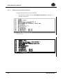
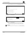
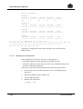
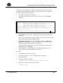
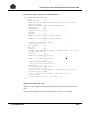
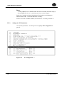
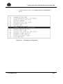
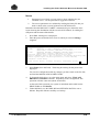
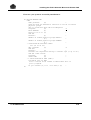
Non-disruptive Replacement of Components
The replacement is done using the hot remplacement menu of the lap top. The
following paragraphs give the guidelines for each type of component.
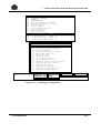
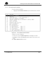
Before carrying out replacement procedures, you must ensure that the Write
Pending status is at 0. Switch to INLINES session mode and send the ’A7’
command.
DA- 1a: DISK SUBSYSTEM=> A7
UTILITY A7 -- Show system devices Attrib/WP/Invalid : TIME: NOV/10/98 12:32:46
----------------------------------------------------NOT RDY WR DIS TYPE DEV
WRT
FMT |
INVALID TRACKS COUNTS
DV# M1234 M1234 M1234 ATTR
PEND PEND |
M1
M2
M3
M4
--------------------------------------------------|----------------------------0F XX-- ..-- mm-- ofs...........
0
0 |
0
0 276240 276240
10 XX-- ..-- mm-- ofs...........
0
0 |
0
0 276240 276240
11 XX-- ..-- mm-- ofs...........
0
0 |
0
0 276240 276240
12 XX-- ..-- mm-- ofs...........
0
0 |
0
0 276240 276240
13 XX-- ..-- mm-- ofs...........
0
0 |
0
0 276240 276240
14 XX-- ..-- mm-- ofs...........
0
0 |
0
0 276240 276240
15 XX-- ..-- mm-- ofs...........
0
0 |
0
0 276240 276240
16 XX-- ..-- mm-- ofs...........
0
0 |
0
0 276240 276240
17 XX-- ..-- mm-- ofs...........
0
0 |
0
0 276240 276240
TOTAL
TOTAL
WR PEND TRACKS / FMT PEND:
M1/M2/M3/M4 INVALID TRACKS:
GLOBAL WR PEND TRACKS / FMT PEND:
GLOBAL M1/M2/M3/M4 INVALID TRACKS:
--- DONE --DA- 1a: DISK SUBSYSTEM=>
3-4
0 / 0 START/END_DV:
0 / 0 / 0 / 0
F /
17
0 / 0
0 / 0 / 0 / 0
77 A7 48UU Rev03
System Repairs
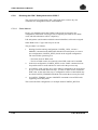
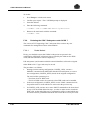
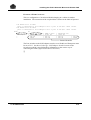
3.3.1
Replacing a Disk-Drive
To replace a disk-drive, follow the procedure described hereafter:
• Identify the disk-drive.
• Replace the identified disk-drive.
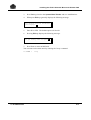
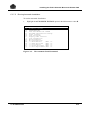
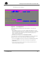
3.3.1.1
Identifying the Disk-Drive
To identify a disk-drive in the cluster:
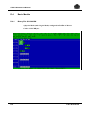
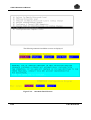
1.
Using the deplacement arrows, go to the Disk Utilities Menu or enter P. A
window is displayed.
CDA7 5330 version
CDA7 5630 version
77 A7 48UU Rev03
3-5
CDA 7 Maintenance Manual
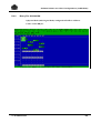
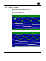
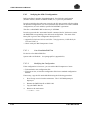
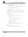
2.
Select the Mark a Volume option or enter A.
CDA7 5330 version
CDA7 5630 version
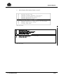
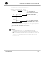
3.
A window is displayed. Highlight the Turn LED ON option and press Enter
to select it. A window is displayed.
Highlight the Single Device option and press Enter to select it. A dialog box
displays the following message: Enter Entire Device Number to Mark.
5.
Enter a four digit number. From the right to the left:
the first digit
is 1 for a data or mirror 1 disk
or 2 for a mirror 2 or parity disk
three last digits
is the number of the disk-drive (DV)
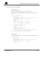
EXAMPLE:
To turn ON the LED of the mirror disk-drive 0: enter 1000. The LED turns ON as
shown in the following figure.
3-6
77 A7 48UU Rev03
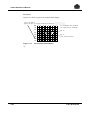
System Repairs
Disk Cage Rear View
LED ON
Mirror 1
Disk 000
Figure 3-1.
Marking the Mirror Disk-Drive 1000
The information of the mirror Disk-drive 1000 is as follows:
❑
77 A7 48UU Rev03
3-7
CDA 7 Maintenance Manual
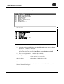
3.3.1.2
Replacing the Identified Disk-Drive
To replace the disk-drive you just identified:
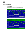
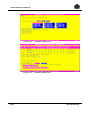
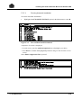
1.
From the main window, select the Hot Replacement Menu or enter Q. A
window is displayed.
CDA7 5330 version
CDA7 5630 version
3-8
77 A7 48UU Rev03
System Repairs
2.
Select the Replace Disk Drive option or press A.
CDA7 5330 version
CDA7 5630 version
A window displays the following information.
Non Mirror
Mirror 3
RDF R1
RDF R3 Mirror For
An R2
Mirror 1
RAID DATA
RDF R2
BCV Volume
Mirror 2
RAID Parity
RDF R3 Mirror For
An R1
Spare Device
3.
Using the arrows, highlight the Mirror 2 option and press Enter. A dialog
box displays the following message: Checking Mirrored Device Ready
Status.
4.
To validate this message, press Enter. Several messages are displayed, then
you are prompted to extract the disk-drive.
77 A7 48UU Rev03
3-9
CDA 7 Maintenance Manual
3-10
5.
Extract the disk-drive. Several messages are displayed, then you are
prompted to place the new disk-drive.
6.
Place the new disk-drive. The data is rebuilt from the mirror disk-drive.
77 A7 48UU Rev03
System Repairs
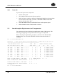
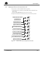
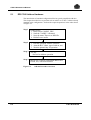
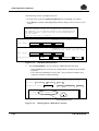
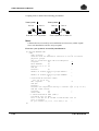
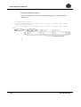
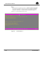
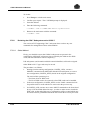
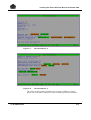
3.3.2
Replacing the Director and Communication Card
This procedure is valid for all DIRECTORS except DA#1:
• switch Disk Director to ENABLE, Channel DIRECTORS to DISABLE on the
operator panel.
• display the Hot replacement menu, then select the card type.
The figure below illustrates schematically the steps involved in this procedure:
DIRECTOR Number Choice
Confirmation ?
1
2
Disable DIRECTOR
3
Extract DIRECTOR
4
Put New DIRECTOR in place
Enable New DIRECTOR
Disable New DIRECTOR
5
6
Pull New DIRECTOR out
7
Put New DIRECTOR in place again
8
Enable New DIRECTOR
Figure 3-2.
77 A7 48UU Rev03
Director and COM Card Replacement Procedure
3-11
CDA 7 Maintenance Manual
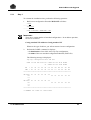
The details of the procedure are as follows:
1.
Enter the number of directors to be replaced.
2.
Transfer the data load from DIR 1 to DIR 2.
3.
Change the DIR 1. A message box is displayed and, it prompts you to enter
the LAN Number.
4.
Enter 2.
5.
Transfer the data load from DIR 2 to DIR 1.
2 <Enter>
Director 2 Must be ONLINE!
Are you sure? Y<Enter>
Please verify Director 2 is disabled by the tiny yellow switch on the board.
Done? Y <Enter>
Please pull director 2 out.
Done? Y <Enter>
Please disable the new directory using the tiny yellow switch on the board.
Done? Y <Enter>
Please put new director in place.
Done? Y <Enter>
Learning Configuration from Hardware.
Directors: 1-2,15-16
Replacement director type: D
New dir_ty: D
Old dir_ty: D
Candidates 1 are: 1
Candidates 3 are: 1
Please disable the new director using the tiny yellow switch on the board.
Done? Y <Enter>
Please wait few seconds before you answer!\
Does the director display "DD" or "BE"? Y <Enter>
Please pull director 2 out\and put back in again to reset the board.
Done? Y <Enter>
New director already displays "DD" or "BE"? Y <Enter>
Please enable the new director using the tiny yellow switch on the board.
Done? Y <Enter>
Please make sure the dials of director 2 are 08.
Done? Y <Enter>
UTILITY FD -- Fast ONLINE IMPL: TIME: SEP/12/95 15:25:45----O.K.
3-12
77 A7 48UU Rev03
System Repairs
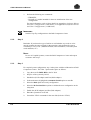
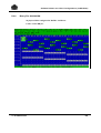
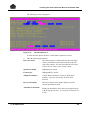
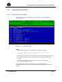
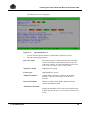
3.3.3
Replacing the DA#1 from the Lap-Top Access Change
NOTE:
Before replacing the DA#1 from the Lap-Top access change, call the Bull
Competence Center.
To define the default access on DA#1:
1.
Using the deplacement arrows, highlight the PC Configuration option or
press L. The Site Information window is displayed.
CDA7 5330 version
CDA7 5630 version
77 A7 48UU Rev03
3-13
CDA 7 Maintenance Manual
3-14
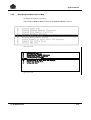
2.
Highlight the RS-232 MUX option and press Enter. The default value of the
MUX ’Local’ director is 02.
3.
Enter the number of the DIRECTOR to MUX ’Local’ director.
4.
At the end of the operation, highlight the Parallel port option: Not in use and
press Enter.
77 A7 48UU Rev03
System Repairs
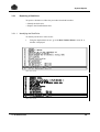
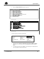
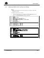
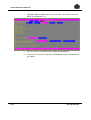
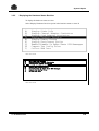
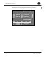
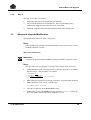
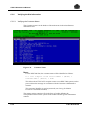
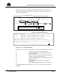
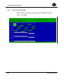
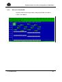
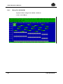
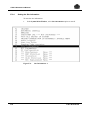
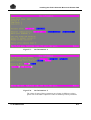
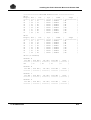
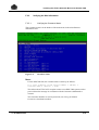
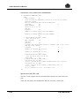
3.3.4
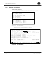
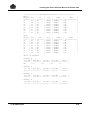
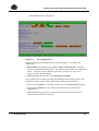
Replacing the Memory Board
To replace the memory board:
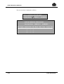
1.
Highlight the Hot Replacement Menu and press Enter.
2.
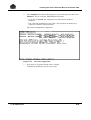
Select the type of board. The procedure is as follows:
Replace memory board
........
Memory MAP: HEX
Slot
03
0000
0008
0010
0028
0C
0020
0028
0030
0038
..........................................
Total bank count: 40
"CACHE START ADD":09977000 (bank: 0004)
"CACHE LAST ADD":F777B000 (bank: 003F)
Slot number (one of 3-C) to replace: 3 Are you sure? Y
0030
0038
.................
Total bank count: 40
"CACHE START ADD": 09977000 (bank: 004)
"CACHE LAST ADD" : 7FFFB000 (bank: 003F)
Slot number (one of 3-C) to replace: C Are you sure? Y
Disable banks 0020-003F
Verifying directors: 1 2 3 14 15 16
Verify DAs have no write pending
Waiting for Channel adapters
Program board in slot: 0C bank: 0380 count: 20 option/F
0030
0038
...........................
Total bank count: 40
"CACHE START ADD": 0997700 (bank: 0004)
"CACHE LAST ADD" : 7FFFB000 (bank: 003F)
Slot number (one of 3-C) to replace: C Are you sure? Y
******Memory test may take considerable time.*******
Do you want to skip the test? Y
Waiting for memory test
Type Ctrl Q to skip forward XX:XX minutes passed
77 A7 48UU Rev03
3-15
CDA 7 Maintenance Manual
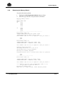
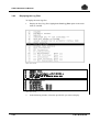
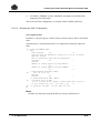
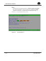
3.3.5
Replacing the Battery
The procedure for replacing the battery is as follows:
1.
2.
3.
4.
5.
6.
7.
8.
Turn the battery OFF.
Remove the two screws from the left of the battery.
Remove the PS1/PS2 Power/Battery cables.
Use the handle to pull the battery backwards (be careful, it is very heavy)
Position the new battery in the cabinet.
Replace the battery retaining screws.
Plug in the PS1/PS2 Power/Battery cables.
Turn the battery ON.
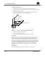
Figure 3-3 shows you how to unmount the lateral panel if necessary:
1. Pull down the lock
2. Slide the right cover
3. Extract the cover
CDA frame
Right cover
Figure 3-3.
1.
2.
3.
4.
3-16
Right cover
Unmounting Lateral Panel
Locate the locking tab under the right cover.
Pull it down to clear the lock.
Slide the cover at the same time to clear it from its four retaining lugs.
Remove the cover by pulling it towards you.
77 A7 48UU Rev03
System Repairs
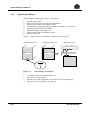
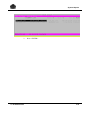
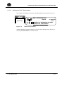
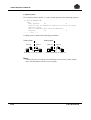
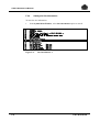
3.3.6
Replacing a Fan Module
Figure 3-4 shows you the location of fan modules:
Fan Tach #1
Fan Tach #2
Fan Tach #4
Fan Tach #3
Figure 3-4.
77 A7 48UU Rev03
Location of Fan Modules
3-17
CDA 7 Maintenance Manual
Unmount the upper cover of the cabinet, and remove the two fan fixing screws
which are accessible from behind, then slide backward and lift slowly as shown in
figure 3-5.
REAR
FRONT
1. Remove the
two screws
Figure 3-5.
3-18
2. Slide backward
3. Lift slowly
Unmounting Fan Modules
77 A7 48UU Rev03
System Repairs
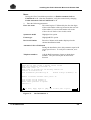
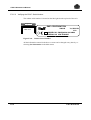
3.3.7
Replacing the Power Supply
Figure 3-6 shows the battery with an extension cable:
PS1
PS2
Bat.
Figure 3-6.
Battery With Extension
1.
Remove the battery and attach it if necessary to an extension cable.
2.
Turn the power supply being replaced OFF at the Power Distribution Module
(PDM).
3.
Disconnect the power supply from the tension buses using the blue key
delivered in the tool kit.
77 A7 48UU Rev03
3-19
CDA 7 Maintenance Manual
Figure 3-7 shows a rear view of the power supplies:
PS1 & PS2 Rear View
Power Supply
Control Cable
AC Power
Cable
Battery
Connection
Figure 3-7.
4.
5.
3-20
Assembling Bolts
to Busbar
Fan Power
Cable
Power Supply (Rear View)
On the rear of the power supply, remove the four connectors:
− Sense cable connector (or power supply control cable in the diagram above)
− AC power connector
− Fan connector
− Battery connector
Unscrew the fixing screw on the front and remove the power supply from its
casing (from the front).
6.
Slide in the new power supply and secure it with the screws from the front,
then tighten the torque bullets with the blue key until they click (the system is
designed to limit tightening to a correct value).
7.
Turn the power supply ON.
8.
Remount the battery in the cabinet removing its extension cable.
77 A7 48UU Rev03
System Repairs
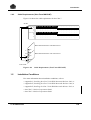
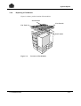
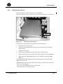
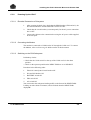
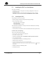
3.3.8
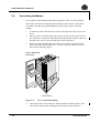
Replacing the Lap-Top
The Lap-Top in the CDA 7 subsystem is a TwinHead PC.
Figure 3-8 shows the Lap-Top in place in the front door of the CDA 7 subsystem.
Plate
Figure 3-8.
Lap-Top in the Front Door
To replace the Lap-Top follow the procedure described hereafter:
1.
Make sure the Lap-Top is off.
2.
Disconnect the plugs from the Lap-Top (tension and logical), leaving the
cables in place.
3.
Unmount the Lap-Top.
4.
Place the new Lap-Top in position, and connect it plug-to-plug.
5.
Power up the Lap-Top, wait for the main menu to appear and enter MS-DOS.
6.
Make a directory New Code and copy the six diskettes in this New Code
directory.
The MICROCODE installation procedure will take place, follow the messages
displayed on the screen.
While the subsystem can operate without the Lap-Top, you should be aware that:
• there is no error logging,
• there are no AUTOCALLS if there is an incident,
• hot replacement is no longer possible.
77 A7 48UU Rev03
3-21
CDA 7 Maintenance Manual
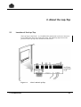
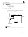
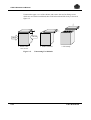
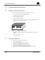
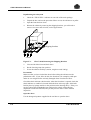
3.4
Disruptive Replacement Procedures
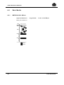
3.4.1
Replacing the Power Distribution Module
The Power Distribution Model replacement procedure is as follows:
1.
Power down the system, including PS1 and PS2.
2.
Disconnect the AC main cable.
3.
Remove the PDM fixing screw.
4.
Remove the Module carefully.
5.
Unplug the PS1, PS2 and Modem power supply cables from the back of the
module, as shown in Figure 3-9, below:
Modem
Figure 3-9.
3.4.2
PS2
PS1
Power Distribution Module
6.
Insert the replacement module by connecting the cables on the back of the
module.
7.
Secure it to the frame.
8.
Power up the system.
Replacing the Adapter Card
To replace the Adapter Card, proceed as follows:
1.
2.
3.
4.
5.
6.
3-22
Power down the system.
Disconnect the SCSI/FIPS cables from the card.
Remove the two fixing screws from the card.
Be sure to take appropriate anti-static precautions.
Remove the card from its casing using its extractors.
Remount the new card by following the unmounting steps in reverse.
77 A7 48UU Rev03
System Repairs
3.5
Alarm Codes and Errors
3.5.1
COM Card Alarm Code
Figure 3-10, below, shows the hexadecimal display on the two COM card types.
3 positions slider switch
(Must be in low position)
Jumper J1
RS232 connector, (Engeenering)
Remote power connector
CR4
CR19
CR15
CR17
CR11
CR10
CR18
CR16
SW5 Attention switch
CR4
CR19
CR15
CR17
CR11
CR10
CR18
CR16
SW6 Enable/Disable switch
(8) Green LED’s (8)
(2) Yellow LED’s (7)
CR9
CR22
CR9
CR20
CR23
CR24
C25
CR26
CR22
Rotary switches
(Must be in "00" position)
SW4 Enable/Disable (Hot replacement)
(Up = Disable / Down = Enable)
Hexadecimal display
COM card
type "028"
Figure 3-10.
3.5.2
COM card
type "692"
Alarm Codes
Director Alarm Codes
There are two Director alarm codes.
• .OF = The DIRECTOR is Off-line.
• .DD = The DIRECTOR is no longer functioning (dead).
77 A7 48UU Rev03
3-23
CDA 7 Maintenance Manual
3.5.3
Environment Faults
To display the environmental faults:
1.
From the main window, select the Statistics Menu or enter O. A window is
displayed.
CDA7 5330 version
CDA7 5630 version
3-24
77 A7 48UU Rev03
System Repairs
2.
Select Display Environment Faults or enter F.
CDA7 5330 version
CDA7 5630 version
77 A7 48UU Rev03
3-25
CDA 7 Maintenance Manual
EXAMPLE:
Figure 3-11 shows a typical environment fault display.
Type N to update
Type Q to quit, A to toggle scanning all directors
Figure 3-11.
00
0
0
0
0
0
0
0
0
10
0
0
0
0
0
0
0
0
20
0
0
0
0
0
0
0
0
30
0
0
0
1
0
1
0
0
40
0
0
0
0
0
0
0
0
50
0
0
0
0
0
0
0
0
60
0
0
0
0
0
0
0
0
70
0
0
0
0
0
0
0
0
33: POWER FAIL ALMPS1
35: CHG STATE ALMPS2
Bit 35
Bit 33
Quit, return to menu
Environment Fault Display
❑
3-26
77 A7 48UU Rev03
System Repairs
3.5.4
Displaying the Memory Error Map
To display the memory error map:
Select Display Memory Errors option in the Statistics menu or enter E.
CDA7 5330 version
CDA7 5630 version
77 A7 48UU Rev03
3-27
CDA 7 Maintenance Manual
The scan start date is displayed as follows:
DISPLAY MEMORY ERRORS MAP
Use data Since
M M/DD/YY
HH/MM/SS
DISPLAY MEMORY ERRORS MAP
Use data Since
MM/DD/YY
HH/MM/SS
DIR Symp Address Bit Slot Bank Date Time
#
#
#
3-28
***
***
***
*
*
*
Count Pipe
**
**
**
77 A7 48UU Rev03
System Repairs
3.5.5
Displaying the Hardware Status Revision
To display the hardware status revision:
Select Display Hardware Revision option in the Statistics menu or enter D.
CDA7 5330 version
CDA7 5630 version
77 A7 48UU Rev03
3-29
CDA 7 Maintenance Manual
The following screen is an example of the information you can display.
Hardware Revision
DIR
DA-01
DA-02
SA-15
SA-16
PN
200-811-909
.....
200-881-902
.....
REV
SN
F19
F19
E02
E01
B1052421362
.....
05914409818
.....
WO HWR
0
0
0
0
905
905
906
906
MEMORY BOARDS
MEM
03
OC
3-30
PN
200-828-903
200-828-903
REV
A4
A4
SN
WO
10591420096
****
77 A7 48UU Rev03
System Repairs
3.6
Log Files
You can consult and copy log files from your Lap-Top. For more information,
refer to the appropriate CDA 7 5330 Product Manual or CDA 7 5630 Product
Manual. There are two product manuals one for 9 GB disks and one for 18 GB
disks. See the Bibliography in the Preface for the reference numbers.
3.6.1
Types of Log Files
The types of Log files you can display are listed below:
LOG_ALL.LOG
Entered in the Lap-Top. When it is full, it is renamed
in LOG_00.LOG, then LOG_01.LOG, etc.
DISKINFO.LOG
displays the disk-module information.
CA_STAT,DA_STAT
Result of Display Channel (or Disk) Directors
command in the Statistics menu.
MEM_ERRS.LOG
Single and multiple memory errors detected by the
Directors. Created with the Display Memory Errors
command in the Statistics menu.
ENVFAULT.LOG
Result of the Display Environment Fault command.
REVISION.LOG
Result of the Display Code Revision command.
SYMPFILE.LOG
Error codes.
77 A7 48UU Rev03
3-31
CDA 7 Maintenance Manual
3.6.2
Displaying the Log Files
To display the main log files:
1.
Display the list of log files: highlight the List Log Files option in the main
menu or enter H.
CDA7 5330 version
CDA7 5630 version
2.
3-32
In the following window, select the specific file you want to display.
77 A7 48UU Rev03
System Repairs
3.
77 A7 48UU Rev03
Press <ENTER>.
3-33
CDA 7 Maintenance Manual
3.6.3
Copying a Log File
If the files are too large, first use the PKZIP utility which is on the PC disk. For
example (with an empty and formatted diskette):
C:\SYMM4\>PKZIP A:<target-file>.ZIP <log-file>.LOG
For PKZIP/PKUNZIP help:
C:\SYMM4>PKZIP<Enter>
C:\SYMM4>PKUNZIP<Enter>
Then copy the files:
C:\SYMM4>DIR *.LOG <Enter>
C:\SYMM4>COPY<filename>.LOG A: <Enter>
3-34
77 A7 48UU Rev03
4. Parts Catalog
4.1
Overview
This chapter provides a list of part numbers for use in ordering replacement parts
for the CDA 7.
4.2
Spare Parts List 5330 (9 GB and 18 GB Disks)
Except for part numbers of the disk modules themselves, these part numbers are
common to systems with 9 GB disks and 18 GB disks.
Description
Disk Module 9 GB
Disk Module 18 GB
Ultra SCSI Director board
Ultra SCSI Adapter Board
Fast Wide SCSI Director Board
Fast Wide SCSI Adapter Board
Fast Wide SCSI Adapter Board
Dual Initiator Adapter Board
Wide Dual Initiator Board
512 MB Memory Board
1 GB Memory Board
Communication Board
Communication Board (Depop)
Front Panel Board
Power Supply Assy.
Battery Box Assy.
EPO Box Assy.
Front Cage Fan Module Assy.
Ultra SCSI Cable Length
10 m
20 m
WSP card
77 A7 48UU Rev03
EMC Part number
100-815-037, 100-815-043
100-815-062
201-277-917, 201-277-927
201-254-900
201-207-917, 201-207-927
201-211-903 without/term & term power
201-254-900 with switch
200-896-917, 200-896-927
201-809-903
200-947-924
200-947-904
200-692-901
200-028-900
201-260-900
071-000-077
100-855-020
100-855-027, 100-855-051
045-000-038
Bull Part Number
91129001-001
91129002-001
76496495-314
4-1
CDA 7 Maintenance Manual
4.3
Spare Parts List 5630 (18 GB and 36 GB Disks)
Except for part numbers of the disk modules themselves, these part numbers are
common to systems with 18 GB disks and 36 GB disks.
Description
Ultra SCSI Director Board
Ultra SCSI Adapter Board
Fibre Channel Director Board
Fibre Channel Adapter Board
Dual Initiator Disk Director
Dual Initiator Adapter Board
4-port Remote Link Director
(RLD for SRDF)
512 MB Memory Board
1 GB Memory Board
2 GB Memory Board
4 GB Memory Board
Communication Board
PCB, Communication Board
Front Panel Board
Power Supply Assy.
Battery Box Assy.
EPO Box Assy.
Front Cage Fan Module
Rear Cage Fan Module
Drives Cage Fan Module
Fan Assembly
18 GB 3.5 inch Disk
36 GB 3.5 inch Disk
PC - Service Processor NT
DC/DC Converter (for PC)
External Modem (US)
Ultra SCSI Cable Length
10 m
20 m
WSP card
4-2
EMC Part number
201-277-977
201-254-900 (with switch)
200-521-970
201-236-907
200-896-977
201-833-903
200-895-974
201-293-982
201-293-942
201-293-922
201-293-902
200-289-901
201-289-901
201-260-900
071-000-126
100-857-021
100-857-012
045-000-038
045-000-037
045-000-062
045-000-068
100-845-044
100-845-136
090-000-058
071-000-089
200-900-055
Bull Part Number
91129001-001
91129002-001
76496495-314
77 A7 48UU Rev03
5. Add-On/Microcode Upgrade
The Add-On procedures are those provided by the BICC (Bull International
Intervention Center). The following paragraphs should be treated as guidelines.
Add-Ons or Microcode upgarades are to be performed either by BICC
personnel or by accredited persons.
77 A7 48UU Rev03
5-1
CDA 7 Maintenance Manual
5.1
DPS 7000 Add-on Hardware
The introduction of standard configuration files has greatly simplified Add-Ons.
This chapter describes how to perform such an add-on to a CDA 7 cabinet already
installed in the configuration. Perform the required operations in the order shown
in Figure 5-1.
Step 1
Step 2
Under GCOS:
1. Build a new CONFIG_FILE.
2. Send the "LABEL" command.
3. Note the name "Dxxxx-xx.BIN"file.
4. BLOAD on a media.
1. Plan the operation with the customer.
2. Alert the BCC (Date, type of add-on, etc.)
3. Wait the planned day of operation
Step 3
"D" day:
- Proceed to Add-on operation
Step 4
Init GCOS (CONFIG, RESTORE/RESTART
COLD, etc.) with new BLOAD.
Figure 5-1.
5-2
Add-On Procedure Overview
77 A7 48UU Rev03
Add-On/Microcode Upgrade
5.1.1
Step 1
To estimate the installation time, perform the following operation:
1.
Build a new configuration file under MNCONF as follows:
S:FGF
......
F:MNCONF
......
N:MD <OLDCONF> <NEWCONF> CDA7
1
3
3
IMPORTANT:
There are a certain number of standard configurations. In an add-on operation,
the rule is as follows:
Config standard XX+Add-On=Config standard YY
Whatever the type of add-on, you will encounter a known configuration.
2.
Perform the LABEL command, it displays:
− the distribution of new disks in the Lap-Top configuration,
− the name of the new standard configuration obtained ("BIN" file).
The following message is displayed:
Lap top configuration dor cda #01
Name of the bin file is: C4000-20 for 5130 model
or D4000-20 for 5330 model
MS
* 01 02 03 04 05 06 09 0A 0B 0C 0D 0E
DEV * 00 01 02 03 04 05 06 07 08 09 0A 0B
********************************************************
SA-15A * 20 21 22 23 24 25
B *
20 21 22 23 24 25
C *
D *
SA-16A * 20 21 22 23 24 25
B *
20 21 22 23 24 25
C *
D *
********************************************************
***LABELS for other 10 controllers
77 A7 48UU Rev03
5-3
CDA 7 Maintenance Manual
3.
Perform the following two commands:
− FIRMGEN,
− BLOAD on a media intended for the next initialization of the new
configuration.
For more information, refer to Basic Models in Appendix A, Software Release
and CDA 7 Configurations (9 GB Disks), or in Appendix D, Software Release
and CDA 7 Configurations (18 GB Disks).
1
3
3
IMPORTANT:
Send the Lap-Top configuration to the Bull Competence Center.
5.1.2
Step 2
Reminder: If you know the type of add-on as well whether any cards are to be
moved, estimate the time required for the operation, and calculate the system
availability to carry it out. (Additional WSPs, cable installation, CDA subsystem
cards and disks, etc.)
NOTE:
In case of Coupled Systems, contact the Bull Competence Center and request
assistance with step 3.
5.1.3
Step 3
For coupled system configuration, step 3 takes place with the collaboration of Bull
Competence Center. The CDA 7 portion takes place as follows:
5-4
1.
Copy the new file IMPL.BIN to the PC disk.
2.
Stop use of the system by GCOS.
3.
Disable SA (SCSI Adaptor) and DA (Disk Adaptor).
4.
In the main menu, highlight the Automatic Install option or enter B.
5.
Select the Disk option and verify configuration.
6.
Select the B=Load and Save option to validate the new configuration to the
subsystem.
7.
Enable SA (SCSI Adaptor) and DA (Disk Adaptor).
8.
Hand the system back to GCOS.
9.
Launch the VTOC command for the new disk (Selective VTOC).
77 A7 48UU Rev03
Add-On/Microcode Upgrade
5.1.4
Step 4
The step 4 procedure is as follows:
5.2
1.
Reinitialize the entire system with the new BLOAD.
2.
Any new disk-modules are in NSTD state. Enter a VOLPREP [short]
command to assign them the label chosen by your client.
3.
Terminate with BLOAD (final)/BLOAD-BACKUP if not already done.
Microcode Upgrade/Modification
This modification affects the CDA 7 subsystem.
NOTE:
If the modification procedure must be performed in one or more steps, contact
the Bull Competence Center.
Microcode Modification
1
3
3
IMPORTANT:
Complete the procedure below before contacting the Bull Competence Center.
NOTE:
This procedure can vary slightly according to the revision of the microcode.
1.
Under MS-DOS, create a working directory and copy the entire C:\SYMM4
directory into it. The procedure is as follows:
C:\SYMM4>CD..
C:\>MKDIR <dirname>
C:>COPY C:\SYMM4\*.* C:\<dirname>
2.
After taking the appropriate operating precautions, stop subsystem operation.
3.
Under MS-DOS, create a New Code directory:
C:\SYMM4> mkdir NewCode
4.
Copy the six diskettes in the NewCode directory.
5.
Under DOS, go to the NewCode directory and enter install. Follow the
procedure under control of the Bull Competence Center.
77 A7 48UU Rev03
5-5
CDA 7 Maintenance Manual
❑
5-6
77 A7 48UU Rev03
A. Software Release and CDA 7
Configurations (9 GB Disks)
This Appendix concerns the CDA 7 with 9 GB disks only.
For the equivalent information for a system with 18 GB disks, see Appendix D.
A.1
Software Level
The software release level is identified according to the following format:
XXXX.yy.zz
where:
XXXX
yy
zz
is the Base Code Family (4 digits)
is the change number in Emulation Code (2 digits)
is the change number in Lap-Top Code (2 digits)
EXAMPLE:
SOFTWARE LEVEL
5263.46.32
❑
77 A7 48UU Rev03
A-1
CDA 7 Maintenance Manual
A.2
Bin Files
For the 9 GB disks, the following BIN files are available:
5300-9M:
D0100-20.BIN
8 HDAs Mirrored (4 M1 + 4 M2)
D0200-20.BIN
16 HDAs Mirrored (8 M1 + 8 M2)
D0300-20.BIN
24 HDAs Mirrored (12 M1 + 12 M2)
D0400-20.BIN
32 HDAs Mirrored (16 M1 + 16 M2)
5300-9S
A-2
D2000-20.BIN
8 HDAs RAID-S (6 Data + 2 Parity)
D3000-20.BIN
12 HDAs RAID-S (9 Data + 3 Parity)
D4000-20.BIN
16 HDAs RAID-S (12 Data + 4 Parity)
D5000-20.BIN
20 HDAs RAID-S (15 Data + 5 Parity)
D6000-20.BIN
24 HDAs RAID-S (18 Data + 6 Parity)
D7000-20.BIN
28 HDAs RAID-S (21 Data + 7 Parity)
D8000-20.BIN
32 HDAs RAID-S (24 Data + 8 Parity)
77 A7 48UU Rev03
Software Release and CDA 7 Configurations (9 GB Disks)
A.3
CDA 7 5330 Disk Configurations
A CDA 7 5330 cabinet is organized into from one to four physical groups (0 to 3)
of eight physical disks each. Each physical group may be:
• six RAID-S devices (8 physical disks), or
• four MIRROR devices (8 physical disks).
The initial cabinet configuration must be:
1.
all physical RAID-S groups, or
2.
all physical MIRROR groups.
The basic models are designated by EMC5330 rmns and the corresponding binary
file is: Drmns-xy.Binary where:
r
m
n
s
x
y
is the number of physical half RAID-S groups (4
physical disks)
is the number of MIRROR physical groups
number of NO-MIRROR physical groups without
spare
number of NO-MIRROR physical groups with one
spare
is the number of SCSI adapters (2 or 4)
is the coding (0 to Hex. F) of the coupled physical
groups (0= for CDA Binary files)
EXAMPLE 1:
Basic Model: CDA5330 with binary file D0200-20 (8 mirror groups)
• no physical RAID-S groups,
• two physical MIRROR groups.
❑
EXAMPLE 2:
Basic Model: CDA5330 with binary file D3000-20 (9 Raid-S)
• three physical RAID-S groups,
• no physical MIRROR groups.
❑
77 A7 48UU Rev03
A-3
CDA 7 Maintenance Manual
A.4
Basic Models
A.4.1
MSPD038-0000: 4 Mirror
8 physical disk drives
4 logical disks
Cache: 2*512 MBytes
Binary file: D0100-20
DEV
00
01
02
03
0
DA-01
0
0
0
0
DA-02
0
0
0
A-4
SA-15A
B
C
DD
20
21
22
23
SA-16A
B
C
DD
20
21
22
23
0
Mirror-1
0
Mirror-2
77 A7 48UU Rev03
Software Release and CDA 7 Configurations (9 GB Disks)
A.4.2
MSPD039-0000: 8 Mirror
16 physical disk drives
8 logical disks
Cache: 2*512 MBytes
Binary file: D0200-20
DEV
00
01
02
03
04
0
DA-01
05 06
07
1
0
1
0
1
0
1
0
DA-02
1
0
1
0
1
0
77 A7 48UU Rev03
1
SA-15A
B
C
DD
20
21
22
23
24
25
26
27
SA-16A
B
C
DD
20
21
22
23
24
25
26
27
0
Mirror-1
1
Mirror-1
0
Mirror-2
1
Mirror-2
A-5
CDA 7 Maintenance Manual
A.4.3
MSPD040-0000: 12 Mirror
24 physical disk drives
12 logical disks
Cache: 2*512 MBytes
Binary file: D0300-20
DEV
DA-01
00 01 02 03 04 05 06 07 08 09 0A 0B
0
1
2
0
1
0
0
2
1
2
0
1
0
0
A-6
2
1
0
DA-02
2
1
2
1
1
2
2
SA-15A
B
C
DD
20 21 22 23 24 25 26 27
SA-16A
B
C
DD
20 21 22 23 24 25 26 27
20 21 22 23
20 21 22 23
0
Mirror-1
1
Mirror-1
2
Mirror-1
0
Mirror-2
1
Mirror-2
2
Mirror-2
77 A7 48UU Rev03
Software Release and CDA 7 Configurations (9 GB Disks)
A.4.4
MSPD041-0000: 16 Mirror
32 physical disk drives
16 logical disks
Cache: 2*512 MBytes
Binary file: D0400-20
77 A7 48UU Rev03
A-7
CDA 7 Maintenance Manual
A.4.5
MSPD042-0000: 6 RAID-S
8 physical disk drives
6 logical disks
Cache: 2*512 MBytes
Binary file: D2000-20
A-8
77 A7 48UU Rev03
Software Release and CDA 7 Configurations (9 GB Disks)
A.4.6
MSPD039-0000: 9 RAID-S
12 physical disk drives
9 logical disks
Cache: 2*512 MBytes
Binary file: D3000-20
77 A7 48UU Rev03
A-9
CDA 7 Maintenance Manual
A.4.7
MSPD040-0000: 12 RAID-S
16 physical disk drives
12 logical disks
Cache: 2*512 MBytes
Binary file: D4000-20
A-10
77 A7 48UU Rev03
Software Release and CDA 7 Configurations (9 GB Disks)
A.4.8
MSPD041-0000: 15 RAID-S
20 physical disk drives
15 logical disks
Cache: 2*512 MBytes
Binary file: D5000-20
77 A7 48UU Rev03
A-11
CDA 7 Maintenance Manual
A.4.9
MSPD042-0000: 18 RAID-S
24 physical disk drives
18 logical disks
Cache: (1*1024 + 1*512) MBytes
Binary file: D6000-20
A-12
77 A7 48UU Rev03
Software Release and CDA 7 Configurations (9 GB Disks)
A.4.10
MSPD043-0000: 21 RAID-S
28 physical disk drives
21 logical disks
Cache: (1*1024 + 1*512) MBytes
Binary file: D7000-20
77 A7 48UU Rev03
A-13
CDA 7 Maintenance Manual
A.4.11
MSPD044-0000: 24 RAID-S
32 physical disk drives
24 logical disks
Cache: (1*1024 + 1*512) MBytes
Binary file: D8000-20
A-14
77 A7 48UU Rev03
B. Error Report (GCOS 7 PRLOG)
This Appendix concerns the CDA 7 with either 9 GB disks or 18 GB disks.
B.1
Channel Exceptions
At the top of the PRLOG you find an area called History report for Channel
Exception. The channel exception logging allows you to define the channel
exception reasons and at the same time information on the cause of this state.
The format of the 16 bytes at the Address is as follows:
Logging LC#0 format:
Bytes 400-401
Verstab
Bytes 402-403
RFU
Byte
Byte
Byte
Byte
Type
Reason
Job Number
Process Number
404
405
406
407
Byte 408
Byte 409
Type
Reason
Byte 40A
Byte 40B
Job Number
Process Number
Byte
Byte
Byte
Byte
Type
Reason
Job Number
Process Number
40C
40D
40E
40F
WSP Firmware revision
level
1st aborted Channel process
2nd aborted Channel
process
Aborted Driver process
If type equal 10 it is the auto-termp.
77 A7 48UU Rev03
B-1
CDA 7 Maintenance Manual
The "Reason" list of Termp code on abnormal execution of GPOS primitive are:
0x01
0x02
0x03
0x04
0x05
0x06
0x07
0x08
0x09
0x0A
0x0B
0x0C
0x0D
0x0E
0x0F
0x10
0x11
0x12
0x13
0x14
0x15
0x16
RC_RQTM
RC_DELRQT
RC_SEPM
RC_SEPMTST
RC_SEVM
RC_NOTIFY
RC_GETDATA
RC_PUTDATA
RC_GETCMD
RC_ENDCB
RC_RESGET
RC_CRCTRL
RC_CRSERV
RC_TERMP
RC_INITSEM
RC_STARTP
RC_SETCTRL
RC_IDS
RC_SEPMT
RC_DLSERV
RC_SCTDESC
RC_GETSCT
Request timer
Delete timer
P operation
P operation test
V operation
Notify (attention)
Terminaison
Create controller
Create server
Semaphores initialization
Start process
Automatic Detailed Status
P operation with timer
Delete server
Descriptors SCT
Primitive getsct
The "Reason" list Termp code on abnormal execution detected by a channel
process are:
B-2
0x50
0x51
0x52
0x53
DEV_TYPE_UNKNOWN
ERR_MES_P0_DRV
ERR_CS_TESTSEM
ERR_CS_CCE
0x54
0x55
0x56
0x57
0x58
0x59
0x5A
ERR_CS_DP_SUPSCSI
ERR_RC_CMDSCSI
ILLEGAL_TAG
TAG_NOT_EXPECTED_HERE
ILLEGAL_TAG_IN_MS_IN_CNL
ILLEGAL_CCE_CODE
ILLEGAL_CMD_SCSI_ASKED
0x5B
ILLEGAL_MSG_SCSI_ASKED
0x5C
0x5D
0x5E
0x5F
ILLEGAL_SCSI_REQUEST
SCSI_COMMAND_ERROR
TIMER_START_SUP_EXPECTED
TIMER_DELAY_SUP_EXPECTED
Device type unknown
Message error from driver or P0
No more used
Internal error, the return code of
cce processing is not correct.
Internal dp_supscsi function error
Internal cmdscsi function error
Tag message error detected
Tag unexpected
Tag error detected
Illegal CCE from P0 received.
Internal error, this SCSI command
is unexpected
Internal error, this SCSI message
is unexpected
No more used
No more used
77 A7 48UU Rev03
Error Report (GCOS 7 PRLOG)
0x60
0x61
0x62
TIMERQUEUE_EXPECTED
TIMERBUSY_EXPECTED
ILLEGAL_PAGE_SELECTED
0x63
0x64
ERR_DRIVER_UNKNOWN
RC_GPOS_UNKNOWN
0x65
0x66
SENDER_UNKNOWN
SENDER_NOT_EXPECTED
0x67
0x68
0x69
0x6A
SRC_SID_UNKNOWN
SRC_SID_NOT_EXPECTED
ILLEGAL_DEVICE_STATUS
SENSE_CODE_UNKNOWN
0x6B
0x6C
0x6D
0x6E
ILLEGAL_SENSE_KEY
ILLEGAL_ERROR_CODE
ILLEGAL_ERROR_CLASS
SCSI_PARAMETERS_ERROR
0x6F
0x70
0x71
0x72
0x73
ILLEGAL_P0_REQUEST
ILLEGAL_P0_REQUEST_TYPE
ERR_STATEDEV
TERMP_DRIVER
DELETE_SERVER
0x74
0x75
0x76
0x77
0x78
NO_REVISION_LEVEL
ILLEGAL_ID_TAPE_POSITION
ILLEGAL_PARTITION_ID
QUEUEP0_OVERFLOW
ILLEGAL_ASC
0x79
ILLEGAL_ASCQ
0x7A
0x7B
ILLEGAL_SVID
TIMEOUT_ABORT
0x7C
ILLEGAL_COM_NB
0x7D
0x7E
0x7F
ERROR_ABORT
UNEXPECTED_ DRIVER_ERR
TOO_MANY_RST_BUS
0x80
TOO_MANY_DRV_RST
0x81
ERR_NOT_EXPECTED
77 A7 48UU Rev03
Internal error, mode select page
not foreseen.
This driver error is unexpected
Return code GPOS unknown or
unexpected.
Message from sender unknown
This message is not expected from
this sender
Source ID unknown
Source ID unexpected
Status unexpected
Additional sense code (SCSI)
incorrect or unknown.
Sense key undefined (SCSI)
Sense code undefined (SCSI)
No more used
Internal error, incorrect parameter
in SCSI command
Driver did termp.
Abnormal delete server
processing.
WSP revision is 00 00 = illegal.
The partition ID received is illegal.
Additional Sense Code illegal or
unknown
Additional Sense Code qualifier
illegal or unknown
Server Id illegal
Time out on abort message
request.
Error driver: Command number
incorrect
Abort SCSI command incorrect
Too many reset reported by the
device
Too many reset reported by WSP
driver
B-3
CDA 7 Maintenance Manual
0x82
0x83
NO_SYC_PARAMETER
LUN_NOT_PRESENT
0x84
UNKNOWN_CONFIG
0x85
UNKNOWN_MESSAGE
0x86
UNKNOWN_SP
0x87
LUN#8_NOT_PERMIT
No SYC parameter in the table.
ID2, LUN # 0 mandatory, is not
present
Configuration is neither RAID-1
nor RAID-5
Monitoring Process Message
received is unknown
No reply from SP during test
switch LUN
LUN # 8 not permit in RAID-1
configuration
The "Reason" list Termp code on abnormal execution detected by a driver process
are:
0x20
0x21
0x22
0x23
0x24
ERR_PIOPROC
ERR_INMESS
ERR_VALTAG
QUEUE_MESS_FULL
PROC_OVF
0x25
0x26
0x27
0x28
0x29
DRIV_OVF
VRAM_OVF
SCRIPT_OVF
ERR_SCHEDULE
ERR_SCRIPTLCA
0x2A
ERR_DATALCA
0x2B
ERR_VRAMLCA
0x2C
ERR_DIFFSENS
0x2D
0x2E
0x2F
0x30
0x31
0x32
ERR_UNKNOWN
ERR_MESSLEN
ERR_CONFIG
ERR_MESSIDENT
ERR_MESSREF
UNEXPECTED_ITNCR
0x33
ITNCR_LOOP
Abnormal value in pioproc pointer
Non identified Message
Unknown Type of message
Message Queue is full
The number of the process
channels under execution is too
big
driv[] table overflow
data overflow in VRAM
script overflow in VRAM
scheduler entry number incorrect
SCRIPT Error parity detected by
the CA
Buffer data error parity detected
by the LCA
access VRAM error parity
detected by the LCA
Single ended device type
connected to the SCSI bus
Unknown LCA Interrupt
Message (out) length too long.
Transfer configuration error.
Identify message error.
Configuration message error.
T NCR without command under
process on the device.
Loop in IT sequence
For more information about the logging area, refer to the technical note DES-NT
209.
B-4
77 A7 48UU Rev03
Error Report (GCOS 7 PRLOG)
B.2
I/O Errors
The PRLOG contains an area dedicated to each logical device named History
report for MSxx FSA. This area reports all types of I/O errors such as: NT with
marginal conditions, ASR, ANR, AMR) and the Attentions.
NOTE:
Some I/O errors and attentions, reported by WSP-A, are filtered by GCOS 7
(AVAIL & PIARS) and are not displayed in the PRLOG.
B.3
Disk PSB/DSB Termination Report
PSB and DSB terminations from DSB0 to DSB15 are listed below, see PA1605
(FSA) for details.
The DSBs beyond DSB15 are specific to devices. The values are given here for
WSP and disc:
PSB1
bit 0
bit 1
bit 2
bit 3
bit 4
bit 5
bit 6
bit 7
PSB2
bit 0
bit 1
bit 2
bit 3
bit 4
bit 5-7
PSB3
bit 0
bit 1
bit 2
bit 3
bit 4
bit 5-6
bit 7
77 A7 48UU Rev03
Modifier Always 1
Status Control (Origin of status)
Channel Program Check (Programming Error)
Detailed Status Pending
Data Error
Hardware condition: Hardware fault
Operational Check
Device Condition
Channel Interface Parity Error
Header Field Missing
Header Field Unrecoverable error
Physical Block Field Missing
Physical Block Unrecoverable
RFU
Unequal Length Check
Device or Path Reserved
RFU
Write Protect
Operating Mode Violation
RFU
Physical End of File
B-5
CDA 7 Maintenance Manual
STANDARDIZED DETAILED STATUS
DSB0
bit 0
bit 1
bit 2
bit 3
bit 4
bit 5
bit 6
bit 7
DSB1
bit 0
bit 1
bit 2
bit 3
bit 4
bit 5
bit 6
bit 7
DSB2
bit 0
bit 1
bit 2
bit 3-5
bit 6
bit 7
Illegal command
Illegal count
Invalid data
Illegal sequence
Resume error
RFU
RFU
Programmed release
Underrun/Overrun (for WSP the meaning is: device busy
longer than expected)
Device not initialized
Device Fault
Device Off-line
Device Interface error
RFU
Device Standby
Device Time-out
No More Space Available
Extra Byte (Last byte not valid)
Partition Overflow
RFU
Manufacturer Defect List(Error occurred)
Current Defect List
"
DSB3: Partition Identifier, 0xFF if no block has been accessed during channel
program execution.
DSB4 to DSB7: Offset in data blocks from the beginning of the partition to the
block error or last block accessed during channel program.
DSB8
bit 0
bit 1
bit 2
bit 3
bit 4
bit 5
bit 6
bit 7
B-6
Recovered Error With Retries
Recovered Error With ECC Correction
Automatic Reassign
Recovered Device Fault
Recovered Underrun/Overrun
Reassign Required
Header/Physical block fielderror
RFU
77 A7 48UU Rev03
Error Report (GCOS 7 PRLOG)
DSB9
bit 0-1
bit 2
bit 3
bit 4
bit 5-7
RFU
Device Explicitly Seized
Device Implicitly Seized
Device Was Reserved
RFU
DSB10 to DSB12: Current Operating Mode
DSB13
Type of Device:
0x00=Illegal Value (Device unknown)
0x01=ST42400N; 2,1Gbytes
0x02=ST41600N; 1,4Gbytes
0x03=XT-4380S; 320Mbytes
0x04=XT-8760S; 680Mbytes
0x06=DFHSS2E ; 2,1Gbytes
0x07=XP32150W ;2,1Gbytes
0x08=XP34300WD;4,3Gbytes
0x80=EMC5130, 4,2 Gbytes
0x81= EMC5330, 9 Gbytes
0x8A=Disk Array 7000, 4 Gbytes
0x8B=Disk Array 7000, 5 Gbytes
0x8C=Disk Array 7000, 9 Gbytes
0x8D=Disk Array 7000, 12 Gbytes
DSB14 to DSB15
Firmware Revision Level
77 A7 48UU Rev03
B-7
CDA 7 Maintenance Manual
CONTROLLER/DEVICE STATUS
DSB16-DSB27
DSB28
DSB29
0x0
0x1
0x2
0x3
0x4
0x5
0x6
0x7
0x8
0x9
0xA
0xB
0xC
0xD
0xE
0xF
DSB30
DSB31
DSB32-DSB35
DSB36-DSB39
B-8
Last failed SCSI command. These bytes report the last
failed command descriptor block as described in SCSI
specification (ANSI X3T9.2/86).
Valid field. This byte reports the first byte of extended sense
table as described in SCSI specification (ANSI X3T9.2/86)
bit 0 tape mark detected
bit 1 EOM
bit 2 ILI (incorrect length indicator)
bit 3 mbz.
bit 4-7 Sense key
No sense information.
Recovered Error.
Device not ready.
Medium Error
Hardware Error.
Illegal request
Unit attention.
Data protect.
Blank check.
Vendor unique sense key error.
Copy Aborted (not used)
Aborted command.
RFU
Volume overflow.
RFU
RFU
Additional sense code
Additional sense code qualifier
Information bytes:
Depend on DSB[28] to [30] values
If DSB[28] to [30] is not equal to "70 01 5D": the
information bytes contains a value which represents the
number of unprocessed blocks or bytes of data resulting
from check condition status for the read,write commands.
If DSB[28] to [30] equals "70 01 5D": the information bytes
contain a value which represents the Degraded mode event:
DSB[32], DSB[33]: SP Error Code like Unsolicited event
log messages. Refer to Unsolicited Event Log Messages in
this document.
DSB[34]: LUN number (0xFF if CRU is not a member of a
LUN)
DSB[35]: CRU Type.
Execution time of the CP between connect received to
termination. (Hexadecimal value in microseconds)
77 A7 48UU Rev03
Error Report (GCOS 7 PRLOG)
DSB40
DSB41-DSB44
DSB45
77 A7 48UU Rev03
SCSI Controller Type:
0x00: MSP
0x10: WSP
0x11: WSP-R
0x12: WSP-B
Complementary device type revision level
If Device Type= 06 IBM disks -->FW Disks
Degraded Mode Information byte:
If Device type = 80 or 81 (EMC) .
0x00 : Normal Mode.
0xXX : Degraded Mode:
0xFF= One or both WSP SCSI termpwr fuse are blown (see
details in DSB104-107)
0x60 = A physical disk configured as Dynamic spare has
been successfuly invoked
0x61 = A Source-Target volume pair has been successfuly
resynchronized.
0x62 = A Source-Target volume pair has been successfuly
resynchronized.
0x63 = Disk adapter failure.
0x65 = An Unsynchronized Source-Target volume pair has
started to resynchronize.
0x66 = A physical disk configured as a Dynamic Spare has
been invoked for SRDF Secondary volume.
0x70 = Temperature fault
0x72 = Environmental fault.
0x73 = One volume of Source-Target volume pair has been
detected as NOT READY.
0x74 = One volume has been detected as write disable.
0x75 = SRDF source / target no longer synchronized.
0x76 = EMC Service processor did not check in with
directors.
0x77 = EMC Service processor was unable to call Customer
center.
0x78 = Reprogramming 12v remained On and should have
turned Off.
0x79 = Cable Missing (Environmental cable is not detected).
0x7A = AC line problems.
0x7B = Battery high state was not detected as expected.
0x7C = Latched envirronmental alarms were detected.
0x7E= Verification process failure
0x7D = SRDF link problem.
0x7E = SRDF link restored.
0x7F = Service processor successfully called the Customer
Center.
B-9
CDA 7 Maintenance Manual
DSB46
DSB47
DSB48-DSB51
DSB52-DSB63
DSB64
DSB65
DSB66
B-10
Vendor Identification
0x00 illegal code.
0x01 SEAGATE
0x03 MAXTOR
0x04 IBM
0x06 BULL
0x08 QUANTUM
0x00 illegal code
0x01=ST42400N; 2,1Gbytes
0x02=ST41600N; 1,4Gbytes
0x03=XT-4380S; 320Mbytes
0x04=XT-8760S; 680Mbytes
0x06=DFHSS2E ; 2,1Gbytes
0x07=XP32150W ;2,1Gbytes
0x08=XP34300WD;4,2Gbytes
0x80= EMC5130, 4,3 Gbytes
0x81= EMC5330, 9 Gbytes
0x8A= Disk Array 7000, 4 Gbytes
0x8B= Disk Array 7000, 5 Gbytes
0x8C= Disk Array 7000, 9 Gbytes
0x8D= Disk Array 7000, 12 Gbytes
Device firmware revision level as returned by the device. (4
ASCII characters )
Current SCSI command. These bytes report the current
command descriptor block as described in SCSI
specification (ANSI X3T9.2/86)
Device Status
0x00 Good.
0x02 Check condition.
0x08 Busy.
0x18 Reservation conflict.DSB109
Driver Status (err_driv)
0x00 NOERR_DRV
0x01 SELECTION_TIMOUT
0x80 RESET_BUS
0xAC ABORT_COMMAND
Message in.
Last message in on SCSI bus
0x00 Command complete
0x01 Extended Message
0x02 Save Data Pointer
0x03 Restore pointer
0x04 Disconnect
0x07 Message reject
0x8X Identify
77 A7 48UU Rev03
Error Report (GCOS 7 PRLOG)
DSB67
DSB68-DSB71
DSB72
DSB73
DSB74
DSB75
DSB76
DSB77
DSB78
DSB79
77 A7 48UU Rev03
Message out.
Last message out on SCSI bus
0x01 Extended message
0x05 Initiator detected error
0x06 Abort
0x07 Message reject
0x08 No operation
0x09 Message parity error
0x0C Bus device reset
0x8x Identify
0xCx Identify
Last event on SCSI bus
File termp code. This byte gives an internal source code of
file which caused the termp (terminate process) condition.
Order termp code in file. This byte gives an internal order
code inside file which caused the termp (terminate process)
condition.
GPOS return code
GPOS return code if primitive "IDS" is unsuccessfully
executed.
GPOS return code if primitive "ENDCB" is unsuccessfully
executed.
Driver first response code if 2 responses (first_err).
0x00 NOERR_DRV
0x02 GENERAL_TIMOUT
0x03 PHASE_MISMATCH
0x04 UNEXPECTED_PHASE
0x05 UNEXPECTED_DISC
0x06 PARITY_ERR
0x07 UNEXPECTED_MESSAGE
0x08 UNEXPECTED_LENGTH
0x09 INITIATOR_SELECT
0x0A ILLEGAL_INST
0x0B WATCHDOG_TIMOUT
0x0C BUS_FAULT
0x0D HOST_PARITY_ERR
0x0E SCSI_GROSS_ERROR
0x0F IT_SCSI_UNKNOWN
0x10 IT_DMA_UNKNOWN
0x11 IT_PROG_UNKNOWN
0x12 ABORT_NCR
0x13 REJECT_MESSAGE
0x14 HANDSHAKE_TIMOUT
RFU
if DSB79=0xFF :error in endcb processing, codend was 0.
B-11
CDA 7 Maintenance Manual
DSB80-DSB95
DSB96-DSB103
DSB104-DSB107
DSB 108-DSB115
DSB116
B-12
DEFINE EXTENT/LOCATE DATA
Drive serial number
If (DSB104 = 0xFF)
DSB105 = 0x00
DSB106 = 0x00 ou 0x01( Fuse SCSI port0 blown)
DSB107 = 0x00 ou 0x01( Fuse SCSI port1 blown)
Else if ( Device type = 80 or 81(EMC) and DSB[45] not
equal to 00)
The information bytes contains a value which represents a
complementary Degraded mode information.
RFU
Error type
0x01 air_error
0x02 rstrecov_successful but error in recovery.
0x03 rstrecov_timeout
0x04 rstrecov_bsy_nrdy (busy or not ready after reset)
0x05 rstrecov_fault (device fault on retry command)
0x06 rstrecov_reserv (reserved after reset)
0x07 rst_unk_err
0x08 rstrecov_fetchcce_err (recovery err during fetch_cce)
0x09 rstrecov_ok
0x0A endcb_modsel_err
0x0B endcb_seize_err
0x0C unlock_recov_err
0x0D arc_test_ok
0x0E arc_test_ko
0x0F reserv_after_chkcond_extd
0x10 modsel_chd
0x80 endcb_release_err: 10xx xxxx =>xx xxxx (compl. err)
77 A7 48UU Rev03
Error Report (GCOS 7 PRLOG)
If DSB116 different 0 and different 1:
DSB117
DSB118
DSB119
DSB120
DSB121
err_driver.
device status
Skc
ASC
ASCQ
If DSB116 equal 1 (AIR error):
DSB122
DSB123
DSB124
DSB125
DSB126
DSB127
77 A7 48UU Rev03
err_driver
device status
Skc
ASC
ASCQ
If (Device type= 8A or 8B or 8C or 8D and DSB[127] =
zyyy yyyy;
if DSB 127 (yyy yyyy) not equal 0 --> reconfiguration
through FGF is needed
z = 0: the Disk Array 7000 mode seen from WSP is
REDUNDANT MODE (2 Storage Processors allocated for
DPS 7000). Default value: REDUNDANT.
z = 1: the Disk Array 7000 mode seen from WSP is NON
REDUNDANT MODE (1 Storage Processor allocated for
DPS 7000)
yyy yyyy:
0x7E= Surveillance process failure
0x7D= Time-out Connect (SP failed or SCSI cable
disconnected)
0x7C= Time-Out Abort (One driver failed)
0x7B= LUN not assigned to the default SP
0x7A= too many driver reset bus
0x79= too many device reset bus
B-13
CDA 7 Maintenance Manual
❑
B-14
77 A7 48UU Rev03
C. Installing the CDA 7 5330 with
Microcode Release 5263
This Appendix concerns Release 5263 of the Microcode only. This release runs on
the CDA 7 with 9 GB disks only.
The following table shows the relationship Microcode Release <-> Disk Size.
Disks
Release 5263
Release 5264
9 GB
Yes
Yes
18 GB
No
Yes
If you are using Microcode Release 5264, Appendix E applies (and not
Appendix C).
C.1
Before Installation
Before installing the CDA 7:
1.
Disconnect AC power supply cable to your machine before doing any work
(except for specific hot replacements of elements).
2.
Do not switch the system on if the ground conductor is disconnected.
3.
Take anti-static precautions (bracelets, anti-static packaging) when working
on electronic parts.
4.
Unless specifically mentioned in the documentation, do not connect or
disconnect elements (for example cards), when live.
5.
Allow the temperature to stabilize before unpacking the cabinet.
77 A7 48UU Rev03
C-1
CDA 7 Maintenance Manual
C.2
Installation Conditions/Auxiliaries
These characteristics are mentioned as a reminder, and are given in the
CDA 7 5330 Site Preparation Guide.
Electrical environment:
• 220 V - 20 A single phase, output by an electric box (International).
• Maximum distance from box 6 feet (2 m).
• 20 A (International) breaker.
• Maximum consumption 1.047 kVA.
Physical dimensions and size:
• Height: 46 inches (116.9 cm)
• Width: 21 inches (53.3 cm)
• Depth: 36 inches (91.4 cm)
• Floor area: 15.75 sq.ft. (1.4 square meters)
• Service width in front and behind: 36 inches (91.4 cm)
Heat dissipation:
3,575 BTU/hr in maximum configuration
C-2
77 A7 48UU Rev03
Installing the CDA 7 5330 with Microcode Release 5263
C.3
Installing the CDA 7 on a Host System
Two ways are possible:
• Installation of a CDA 7 subsystem in an existing configuration. This case is
described hereafter.
• Installation of a CDA 7 subsystem delivered with a new system. For more
information, refer to the On-Line Help of the BUILD P2 command of FGF.
C.3.1
Unpacking the CDA 7
Two packages are delivered on pallets:
• the first package contains the subsystem (the largest package).
• the second package contains:
− the modem and its power supply
− the documentation
− tools and miscellaneous cables
You will find two self-adhesive envelopes on the main cardboard box containing:
• depalletizing instructions
• a sheet with the serial numbers of the cards and disks delivered (keep this sheet)
Contents of the second package
There are the following main elements:
• the AC power source cable for the subsystem
• the modem connection cable
• a media box (MICROCODE). The media box must be present on the site.
• a 5/16 hexagonal spanner
• a small insulated screwdriver (for handling rotactors)
• a plastic tool (for card resets)
• a spanner with expansion rod to access connection nuts
• a black/red connection cable used as extension cable if the battery is taken out of
the cabinet
• loopback connectors for Bus&Tag cables
• an anti-static bracelet
77 A7 48UU Rev03
C-3
CDA 7 Maintenance Manual
De-palletizing the subsystem
1.
Check the "TIP-N-TELL" indicator on one side of the main package.
2.
Unpack the box, and cut the protection film to access the cabinet on its pallet.
3.
Open the front and rear doors.
4.
Release the cabinet by removing the shipping brackets, you will need to
remove six screws and six bolts, see the figure below.
3 Screws
Shipping brackets
3 bolts
Figure C-1.
CDA 7 5330, Removing the Shipping Brackets
5.
Close and lock the front and back doors.
6.
Put the lowering ramp into position.
7.
Lower the cabinet carefully (caution, weight exceeds 300 kg).
Precautions
Make sure that you have locked the doors before tilting the cabinet onto the
palletization rails. If you fail to do this, the front door (for example) could open
under its own weight and be seriously damaged when it touches the floor.
Check the shock indicator (shockwatch): when the front door is opened, check the
shock indicator (a small box) located inside the door at the top right. Steel balls
held in place by springs must be in the position on the drawing above. If they are
not, the cabinet has undoubtedly been subjected to a shock with sufficient
amplitude to make the balls fall, and you may need to make a more detailed
inspection.
Open the doors
Use the hexagonal spanner supplied in the tool box to open the doors.
C-4
77 A7 48UU Rev03
Installing the CDA 7 5330 with Microcode Release 5263
C.3.2
Powering Up the CDA 7
C.3.2.1
Electrical Connection of Subsystem
C.3.2.2
1.
After opening the back door, check that the PDM breakers (EPO and AC), the
PS1 and PS2 breakers and the BATTERY switch are OFF.
2.
Check that the circuit breaker, (customer panel), for the AC power connection
box is OFF.
3.
Connect the cabinet to the connection box using the AC power cable supplied
in the tool pack.
Connecting the Modem
The modem is connected to COM2 on the PC through the COM card. To connect
the Modem, refer to Connecting the Modem earlier in this document.
C.3.2.3
Switching on the CDA Subsystem
Preliminary checks:
• Check that the "slider switch" at the top of the COM card is in the down
position.
• Check on the operator panel that the DIRECTORS are set to DISABLE.
Procedure in the following order:
1.
Electrical control panel circuit breaker ON.
2.
PS1 and PS2 breaker ON.
3.
BATTERY switch ON.
4.
EPO switch ON.
5.
AC switch ON.
You can monitor the subsystem loading traffic on the front of the DIRECTORS.
Loading can takes about 25 minutes, and is finished when the DIRECTORs
display 0F.
77 A7 48UU Rev03
C-5
CDA 7 Maintenance Manual
NOTE:
A faulty DIRECTOR or a DIRECTOR which has been badly initialized displays
the value DD. In this case, restart the operation or contact support.
In this case, "loading" includes initialization of the hardware and loading the
MICROCODE (IML = Initial MICROCODE Loading).
If there is no traffic on DIRECTORS, check that the PC is actually switched on.
C.3.3
Setting the CDA 7 Internal Clocks
To set the internal clocks of the CDA 7 subsystem:
• Set the PC internal clock.
• Load the defined values to the CDA 7 subsystem clock.
C.3.3.1
Setting the PC Internal Clock
When CDA 7 subsystem is switched on:
1.
Set the PC Lap-Top date under DOS. To do this:
− Enter the C:\Symm4 directory.
− Enter the following command:
C:\Symm4 > date
2.
The current date is displayed. Enter the new date.
Using in the following format: mm-dd-yy, enter the date.
3.
Using in the following format: HH-mm-ss, enter the time.
4.
Validate the parameters.
5.
Ask for a remote link to the Bull Competence Center.
The information you provided is stored in a Lap-Top file called SITEINFO.DAT.
C-6
77 A7 48UU Rev03
Installing the CDA 7 5330 with Microcode Release 5263
C.3.3.2
Loading the Defined Parameter Values to the CDA 7 Clock
To set the SYMMETRIX clock of the CDA 7 subsystem:
1.
Set All directors OFF line.
2.
In the main window, select the Maintenance Menu or press M.
A)
B)
C)
D)
E)
F)
G)
H)
I)
J)
K)
L)
M)
N)
O)
P)
Q)
INLINES
AUTOMATIC INSTALL
ANALYZE
SUBSYSTEM IML
VTOC ALL DRIVES IN SYSTEM
ON LINE Configuration Change
Start logging
List Log files
Display Code revision
Site Information
MII Parameters
PC Configuration
*** Maintenance
Menu ***
*** RDF Utilities
Menu ***
*** Statistics
Menu ***
*** Disk Utilities Menu ***ilities
*** Hot Replacement Menu ***
Figure C-2.
3.
77 A7 48UU Rev03
Menu ***
Symm4 Main Window
Select the Set Symmetrix Clock option or press K. You automatically launch
the procedure and the parameters of the PC configuration file are entered in
the CDA 7. The Symm4 Main Window is displayed.
C-7
CDA 7 Maintenance Manual
C.3.4
Setting the Site Information
To enter the site information:
1.
In the Symm4 Main Window, select Site information option or enter J.
A)
B)
C)
D)
E)
F)
G)
H)
I)
J)
K)
L)
M)
N)
O)
P)
Q)
INLINES
AUTOMATIC INSTALL
ANALYZE
SUBSYSTEM IML
VTOC ALL DRIVES IN SYSTM
ON LINE Configuration Change
Start logging
List Log files
Display Code revision
Site Information
MII Parameters
PC Configuration
*** Maintenance
Menu ***
*** RDF Utilities
Menu ***
*** Statistics
Menu ***
*** Disk Utilities Menu ***
*** Hot Replacement Menu ***
Figure C-3.
Site Information - 1
The following three screens are displayed in sequence:
Site information
Enter site name: G7XXXX CUSTOMER MILANO
Symmetrix model: 57xx 54xx "53xx"
Format type: IBM
DELTA
"BULL " COVIA_A
COVIA_B
Enter first Phone No: xxxxxxxxxxxx
Network:
Enter SYMMETRIX modem Phone No: xxxxxxxxx
Enter Customer Phone No: xxxxxxxxx
Enter Box Serial Number: xxxxxxxxx
Hardware Configuration:
memory size: xxxxMB
Enable Machine Initiated Interrupts? N
Enable Automatic Calls to FieldWatch? N
Notify operator on? N
call home result? Y
Report AC errors? Y
Enter second Phone No: xxxxx.....
Network:
Enter third Phone No: xxxxx.....
Network:
Enter fourth Phone No: xxxxx.....
Network:
BT-CORK
BT-CORK
BT-CORK
BT-CORK
to move, PgUp , PgDn to jump, F10 to exit, Esc to quit. More
Figure C-4.
Site Information - 2
To enter the three phone numbers, call the Bull Competence Center.
C-8
77 A7 48UU Rev03
Installing the CDA 7 5330 with Microcode Release 5263
NOTE:
During the CDA 7 installation procedure, set Enable Automatic Calls to
FieldWatch? to N. After the installation, verify the connection by changing
Enable Automatic Calls to FieldWatch? to Y.
2.
Enter the following parameters:
Enter site name:
This name begins G7 followed by the four last digits
of the serial number of the tag located on the rear side
of the cabinet. For more information refer to the
Cabinet Serial Number, later in this section.
Symmetrix model
Highlight 53xx option.
Format type
Highlight BULL option.
Box Serial Number
Enter the Cabinet serial number displayed on the
cabinet identification label.
Automatic Calls to Fieldwatch
During the installation, leave this parameter equal to N
except special cases. To verify the connection, set it
to Y.
Telephone numbers
Call the Bull Competence Center to obtain these
numbers. They are used by the AUTOCALLS
function.
Site information
Phone No: in user "first " second third fourth
Wait for connection in seconds: 60
Modem rest (sec): 10
Time limit in seconds for one dailing session: 30
Collect IO statistics? N
Call Fieldwatch periodically? N
Period in days (0=Never): 14
Number of minutes between error pcils: 20
Site filter for CA errors? N
Site filter for DA errors? N
Enter sense patterns to ignore:
COM Port: 1
to move, PgUp, PgDn to jump, F10 to exit, Esc to quit.
Figure C-5.
77 A7 48UU Rev03
More
Site Information - 3
C-9
CDA 7 Maintenance Manual
Note some redundancies between the two first Site information screens.
Site information
Modem port:
Modem Baud rate: 9600
Parity: N
Stop bits: 1
Data bits: 8
Parrallel port: "Not in use" RS-232 MUX
Use only black and white? N
Return to default colors? N
Modify screen colors? N
Reboot after calling home? N
Periodically reset modem? N
to move, PgUp, PgDn to jump, F10 to exit, Esc to quit.
Figure C-6.
More
Site Information - 4
Site information
Environmental tests from PC: Enabled Disable:
Existing EPOs: EPO1 EPO2
Active Heat Sensors:
Sensor 1
Comm Board: 0
to move, PgUp, PgDn to jump, F10 to exit, Esc to quit.
Figure C-7.
More
Site Information - 5
The values of some of these parameters may change in different versions,
please refer to the Bull Competence Center to obtain up-to-date parameters.
1
3
3
IMPORTANT:
Remember that the function of the ESCape key is to exit without modification.
C-10
77 A7 48UU Rev03
Installing the CDA 7 5330 with Microcode Release 5263
3.
Press F10 to go back to the Symm4 Main Window and save modifications.
4.
When press ESCape generally displays the following message:
All changes will be abandoned.
Quit anyway? Y
5.
Enter Y for YES. The default option is N for NO.
6.
Pressing ESCape displays the following message:
Do you really want to quit? Y
7.
Press Enter to return to MS-DOS.
You can return to the main menu by entering the "loop" command:
C:\SYMM4 >
77 A7 48UU Rev03
loop
C-11
CDA 7 Maintenance Manual
C.3.5
Verifying the Site Information
C.3.5.1
Verifying the Customer Name
The Customer name is in the header of the main menu in the miscellaneous
information area:
Figure C-8.
Customer Name
NOTE:
For the DPS 7000 line, the customer name will be identified as follows:
G7 + last 4 digits of the serial number + (Blank) +
Customer Name + (Blank ) + Town
This allows the AUTOCALL reception center to sort DPS 7000 systems, and to
process/direct the message in accordance with the Customer’s Maintenance
contract.
This customer identifier is used as password (see Setting the Modem
Parameters described hereafter).
The remote station contains a file in the form of a table defining the
correspondence between the system serial number and the type of maintenance
contract.
C-12
77 A7 48UU Rev03
Installing the CDA 7 5330 with Microcode Release 5263
C.3.5.2
Verifying the CDA 7 Serial Number
The cabinet serial number is located on the label glued at the top back of the rack.
Top cover
EMC CORPORATION
V 50/60 Hz
10 A
MODEL NO EMCFRA5330 5330-9M08
SERIAL NO CRK 81800557
208/240
Rear view
Figure C-9.
Cabinet Serial Number
All the information entered in the above screens can be changed at any time by reselecting Site Information in the Main menu.
77 A7 48UU Rev03
C-13
CDA 7 Maintenance Manual
C.3.6
Setting the Modem Parameters
To set the Modem parameters:
1.
Under the SYMM4 prompt, enter the following command:
C:\SYMM4> scsetup
The following dialog box is displayed.
SymmCom
Target Configuration
Modem
Multitech MULTIMODEM
Comm Port
COM (3F8 hex- IRQ4)
Port Rate
19200
Connectivity
Allowed
Encryption
OFF
Call Back disabled
Prefix if any to access an
outide line
Is Symmetrix attached to an
Ethernet LAN for use as its
communication mode ? (Y/N)
Generate Configuration
Figure C-10.
C-14
Y
Modem Parameter Setting
2.
At first installation, change the password. This password is generally
G70xxx, where xxx are the three last digits of the serial number of the CDA 7
subsystem.
3.
Answer N to the first message: CDA 7 5330 is not attached to an Ethernet
LAN. The Make a Model window is displayed.
4.
Enter N. Successive dialog boxes are displayed.
77 A7 48UU Rev03
Installing the CDA 7 5330 with Microcode Release 5263
5.
To enter the values of the parameters displayed in the above table, answer to
these dialog boxes as follows:
Modem
Multitech MULTIMODEM
Comm Port
COM2 (2F8 hex.)
Port Rate
9600
Connectivity
Allowed
Password Change
Enter G7xxx.
Encryption
OFF
Call Back disabled
Press Enter.
Prefix if any to access an outside line
Press Enter.
Generate Configuration
Y
After the last message, you automatically go back to the DOS prompt.
6.
C.3.7
To display the Symm4 Main window, enter the loop command.
Verifying the CDA 7 Configuration
Bull has defined a number of standard models, for which the configuration
(number of disks, number of DIRECTORS, etc.) is precisely determined.
In order to initialize the subsystem correctly, the PC must contain a file describing
the installed configuration; it is obvious that this file describes one of the standard
configurations (or basic models) specified in Bull/EMC agreements.
This file is called IMPL.BIN in the directory:
C:\SYMM4
In order to proceed this "Automatic Install" command, the PC disk must contain
the IMPL.BIN corresponding to the delivered configuration.
C.3.7.1
List of Available BIN Files
For a system with 9 GB disks, see paragraph A.2 (Appendix A).
77 A7 48UU Rev03
C-15
CDA 7 Maintenance Manual
C.3.7.2
Standard Configuration
The standard configuration of a basic CDA 7 contains:
• 2 to 4 SCSI Channel DIRECTORS
• 2 Disk DIRECTORS
• 2 Memory boards
• 8 physical disk-modules
For more information about CDA 7 subsystems with 9 GB disks, refer to the
Appendix A Software Release and CDA 7 Configurations (9 GB Disks) earlier in
this document.
C.3.7.3
Checking the Configuration
To check the configuration on the laptop, you can choose the following procedure:
C-16
1.
From the main menu, using the Up/Down arrows select the Maintenance
menu or press M.
2.
Using the Up/Down arrows, select the View IMPL files command or press B.
The four following screens are displayed:
77 A7 48UU Rev03
Installing the CDA 7 5330 with Microcode Release 5263
A)
B)
C)
D)
E)
F)
G)
H)
I)
J)
K)
L)
M)
N)
O)
P)
Q)
INLINES
AUTOMATIC INSTALL
ANALYZE
SUBSYSTEM IML
VTOC ALL DRIVES IN SYSTEM
ON LINE Configuration Change
Start logging
List Log files
Display Code revision
Site Information
MII Parameters
PC Configuration
*** Maintenance
Menu ***
*** RDF Utilities
Menu ***
*** Statistics
Menu ***
*** Disk Utilities Menu ***
*** Hot Replacement Menu ***
A)
B)
C)
D)
E)
F)
G)
H)
I)
J)
K)
L)
M)
N)
O)
P)
Q)
Command Files Menu
View IMPL Files
Check Diskette Files (Checksum)
Download Disk microcode
Download EPROM
Factory Format A11 Disks
Mean Time Patch Fix
Automatic MTPF
Reverse MTPF
Clear Lost Writes
Set Symmetrix Clock
Display Current Configuration
Display Emulation Revs
Online Patch Load
COM Boards Commands
Hardware Stamp Directory
Hardware Stamp Memory
IMPL file to report IMPL4134.BIN
IMPL4129.BIN
Figure C-11.
77 A7 48UU Rev03
IMPLCA.BIN
TEST
IMPLDA.BIN
"IMPL.BIN
"
Checking the Configuration
C-17
CDA 7 Maintenance Manual
And an example of the final result:
IMPL File: C:\SYMM4\IMPL.BI1
08/29/97 15:14:04
aced: ACED version: 4220 internal date: 08/29/1997
================== IMPL HEADER ==================
Host:
Server/Bull
Emulation:
FBA
Disk size:
:Mix
Physical drives:
16
Volumes:
8
Mirrors:
8
Memory (MB):
1024
Hot Spare:
Disable
Mirroring:
Enable
RDF:
Disable
False disconnect:
Disable
Auto restore lost writes:
Enable
Perma-Cache:
Disable
Prefetch:
Enable
Record Cache:
Disable
FIFO / LRU:
LRU
Cache Fast Write:
Enable
Write Pending Ceiling (%):
80
Cache F.W. Track Ceiling:
32000
9370 Mode:
Disable
Multiplexing:
Enable
DA DMA Burst:
0
CA DMA Burst:
0
Image:
09
SCU ID:
E0
Controller ID:
30
Diagnostics:
No
Battery Backup:
180
Shutoff:
300
Track Mask:
FFFF
Processor Instruction Cache: Enable
Processor Data Cache:
Enable
PC Alive:
Enable
================== Directors ==================
01 | 02 | 03 | 04 | 05 | 06 | 07 | 08 | 09 | 10 | 11 | 12 | 13 | 14 | 15 | 16 |
--------------------------------------------------------------------------DA4 |DA4 |
|
|
|
|
|
|
|
|
|
|
|
|SA4 |SA4 |
---------------------------------------------------------------------------
C-18
77 A7 48UU Rev03
Installing the CDA 7 5330 with Microcode Release 5263
================== Detailed Director list ==================
DA-01
Target | Dev. |
Int.
| Cyl. |
Label
|
Flags
====== | ==== | ======== | ====== | ========== | ==============
00
| 00
| C0
| 18414 | SYM000
| M1
01
| 04
| C1
| 18414 | SYM004
| M1
02
| 02
| D0
| 18414 | SYM002
| M1
03
| 06
| D1
| 18414 | SYM006
| M1
04
| 03
| E0
| 18414 | SYM003
| M2
05
| 07
| E1
| 18414 | SYM007
| M2
06
| 01
| F0
| 18414 | SYM001
| M2
07
| 05
| F1
| 18414 | SYM005
| M2
|
|
|
|
|
|
|
|
|
|
DA-02
Target
======
00
01
02
03
04
05
06
07
|
|
|
|
|
|
|
|
|
|
|
|
|
|
|
|
|
|
|
|
Dev.
====
01
05
03
07
02
06
00
04
|
|
|
|
|
|
|
|
|
|
Int.
========
C0
C1
D0
D1
E0
E1
F0
F1
|
|
|
|
|
|
|
|
|
|
Cyl.
======
18414
18414
18414
18414
18414
18414
18414
18414
|
|
|
|
|
|
|
|
|
|
Label
==========
SYM001
SYM005
SYM003
SYM007
SYM002
SYM006
SYM000
SYM004
|
|
|
|
|
|
|
|
|
|
Flags
==============
M1
M1
M1
M1
M2
M2
M2
M2
SA-15: (4 Channels)
Channel:
1st dev
========
000
A
| last dev | 1st chn | last dev |
count |
| ======== | ======== | ======== | ======== |
| 07
| 20
| 27
| 8
|
Channel: B
1st dev | last dev | 1st chn | last dev |
count |
======== | ======== | ======== | ======== | ======== |
Channel: C
1st dev | last dev | 1st chn | last dev |
count |
======== | ======== | ======== | ======== | ======== |
Channel: D
1st dev | last dev | 1st chn | last dev |
count |
======== | ======== | ======== | ======== | ======== |
77 A7 48UU Rev03
C-19
CDA 7 Maintenance Manual
SA-16: (4 Channels)
Channel:
1st dev
========
000
A
| last dev | 1st chn | last dev |
count |
| ======== | ======== | ======== | ======== |
| 07
| 20
| 27
| 8
|
Channel: B
1st dev | last dev | 1st chn | last dev |
count |
======== | ======== | ======== | ======== | ======== |
Channel: C
1st dev | last dev | 1st chn | last dev |
count |
======== | ======== | ======== | ======== | ======== |
Channel: D
1st dev | last dev | 1st chn | last dev |
count |
======== | ======== | ======== | ======== | ======== |
================== System IDs ==================
00 | 01 | 02 | 03 | 04 | 05 | 06 | 07 | 08 | 09 | 0A | 0B | 0C | 0D | 0E | 0F |
==================================================================
E0 | E0 | E0 | E0 | E0 | E0 | E0 | E0 |
This shows a configuration with 16 Mirrored disks, and 4 SCSI Channel
DIRECTORS.
C.3.7.4
Modifying the Configuration
If the configuration is incorrect, there are several solutions:
• The Bull Competence Center download your IMPL.New file.
• The Bull Competence Center may be present at the installation and have the
diskette containing standard files.
If necessary, copy the file under MS-DOS using the following procedure:
1.
Press Escape to exit from the main menu. The C:\SYMM4 prompt is
displayed.
2.
Rename the IMPL.Bin file as IMPL.Old.
3.
Copy the IMPL.Bin file.:
4.
Return to the main menu:
C:\SYMM4 > LOOP
C-20
77 A7 48UU Rev03
Installing the CDA 7 5330 with Microcode Release 5263
C.3.7.5
Running Automatic Installation
To run the Automatic Installation:
1.
Highlight the AUTOMATIC INSTALL option in the Main menu or enter B.
A)
B)
C)
D)
E)
F)
G)
H)
I)
J)
K)
L)
M)
N)
O)
P)
Q)
INLINES
AUTOMATIC INSTALL
ANALYZE
SUBSYSTEM IML
VTOC ALL DRIVES IN SYSTEM
ON LINE Configuration Change
Start logging
List Log files
Display Code revision
Site Information
MII Parameters
PC Configuration
*** Maintenance
Menu ***
*** RDF Utilities
Menu ***
*** Statistics
Menu ***
*** Disk Utilities Menu ***
*** Hot Replacement Menu ***
Figure C-12.
77 A7 48UU Rev03
The Automatic Install Command
C-21
CDA 7 Maintenance Manual
The following screens are displayed in turn.
• In each screen, press the up/down/right/left keys to highlight your choice.
• Press Enter to validate the highlighted parameter and go to the next line or next
screen.
WARNING: USE OF CERTAIN FEATURES IN THIS MICROCODE REQUIRE
SEPARATE SOFTWARE LICENCE NOT AUTOMATICALLY INCLUDED WITH
THE SYMMETRIX. IF YOU ARE NOT CERTAIN IF YOU ARE ENTITLED TO
USE THESE FEATURES, CONTACT YOUR EMC ACCOUNT REPRESENTATIVE
FOR ASSISTANCE.
Press the space bar to continue ...
SYMMETRIX Configuration Program
Revision 1.12 Date: June 26, 1995
User level:
"Standard"
Advanced
Expert
SYMMETRIX Configuration Program
Revision 1.12 Date: June 26, 1995
User level:
"Standard"
Configuration source:
Figure C-13.
2.
Advanced
"Disk
Expert
"
System
Production
Default
Automatic Install Screens
Select Standard/Disk. The PC reads the IMPL.BIN file from disk.
− If the System option is chosen, the configuration is read from the installed
hardware.
− If it is the first installation of your CDA 7, the procedure terminates by a
request to format the subsystem disks.
SYMMETRIX Configuration Program
Revision 1.12 Date: June 26, 1995
User level: "Standard"
Configuration source:
Advanced
"Disk
"
Expert
System
Production
Default
"Disk" option should be chosen, only for new systems.
It requires VTOC formatting of all volumes!
Does your system contain live data?
N
First installation only
Figure C-14.
C-22
Warning before a Disk-Device Format
77 A7 48UU Rev03
Installing the CDA 7 5330 with Microcode Release 5263
The next screen gives a warning concerning a format operation on disks. The
following dialog box asks if the PC is connected to a CDA 7 cabinet ("box"),
which is usually the case.
Current procedure
First installation only
Upgrade/modification operations
SYMMETRIX Configuration Program
Revision 1.12 Date: June 26, 1995
User level: "Standard"
Configuration source:
Advanced
"Disk
"
Expert
System
Are you connected to be actual box?
Production
Default
Y
The box is in fact the CDA cabinet
CURRENT CONFIGURATION:
DA Code:
REVISION: CC73DA01; CHECKSUM: 01EF2E96: DATE: 01/27/1995
MTPF number: 000059C1; MTPF date: 07/06/1995;
SA Code:
REVISION: FB73AA01; CHECKSUM: 018DCCBC: DATE: 01/27/1995
MTPF number: 000059C7; MTPF date: 07/06/1995;
RS232 baud: 33400 8 bits; Cache Fast Write Ceiling: 80%;
Cache Fast Write Track Ceiling: 32000
Number of volumes: 8
Emulation: FBA:Mix; Time to shut off Battery: 120 Seconds; Mirroring: YES;
Prefetch: Yes; Dynamic Spare: NO; Microprocessor I/O cache: YES/YES;
Server/Bull: Online Tests;
<L>oad, <S>ave, <B>oth, <C>hange, <D>isplay, <A>dvanced, <Q>uit?
Figure C-15.
C
Installation Dialog
The final screen contains several options (see the line at the bottom of the screen):
L
S
B
C
D
A
Q
Load and activate the (new) configuration
Save the configuration on disk after modification
without loading it
Save and Load at the same time after modification
Change (or adapt) what is displayed
Display the IMPL.BIN file as described above in the
previous section
Advanced functions reserved for specialists or
engineering
Exit without changing and return to the main menu
Now that the IMPL.BIN file is correct , you can go on and select the "LOAD"
command.
77 A7 48UU Rev03
C-23
CDA 7 Maintenance Manual
C.3.7.6
Running the Change Command
To change (or check) the configuration or some parameters, proceed as follows:
1.
If you modify an existing configuration in the case of an Add-on, select
Change to make any changes to the configuration, or to check the
configuration.
CAUTION:
This procedure presents certain dangers for the customer’s data, so you must
contact Bull Competence Center or an experienced person before proceeding.
The F10 key is used to exit and save. If you accidentally modify and change a
live configuration, there is a risk of destroying data.
To quit without saving any change, press ESCape.
The following screens are displayed:
2.
Highlight the chosen parameter.
3.
Press Enter.
Fixed Block Architecture
Bull DPS 7000
SYMMETRIX III Configuration Information
SYSTEM
-----System Serial Number: 0008116000177
Emulation code:
"FBA
"
Host system:
IBM
Server/UOD
AS/400-480R
Drive Capacity:
1.2 GB
Mix/Hyper"
3300-OLD
UNISYS
SERIES-A
Mix
1.6 GB
3390
3300-NEW
Server
AS/400-240
2.2 GB
MIX-CKD
"Server/Bull"
AS/400-480
3.0 GB
9.0 GB
Enable Dynamic Path Reconnection? N
RDF System? N
Raid-S mode? N
Open Systems Concurrent Copy?
N
to move, PgUp, PgDn to jump, F10 to exit, Esc to quit.
Figure C-16.
C-24
More
The Change Command - 1
77 A7 48UU Rev03
Installing the CDA 7 5330 with Microcode Release 5263
Pressing "Enter" on this selection causes
the map to be displayed
SYMMETRIX III Configuration Information
Enter Total System memory (MB): 1024
Enter SCU-ID number: E0
Enter CTRL-ID number: 30
Enable Mirroring? Y
Enable Dynamic Spare? N
Number of PHYSICAL drives: 16
Drive type: Cuda-9X
Custom or default, internal
labels, not visible by GCOS
8 Logical Volumes in the system.
"Edit Directors/Volumes/Channels map"
Perma Cache option:
Labels:
"NOT used
Custom Labels
"
Perma Cache used
"Default Labels"
to move. 8
PgUp,
exit,MBEsc to (100%))
quit.
VolsPgDn to jump,
138408F10
of to
138931
Emulation
3370-12Y
3370-12
Figure C-17.
4.
Cylinders
18414
958
Count
8
0
More
Type
RDF
2-MIR
NORMAL
Grp Range
000-007
The Change Command - 2
Highlight the Edit Directors/Volumes/Channels map option, and then press
Enter. A screen displays the distribution of volumes as shown in the figure
above.
The following screen contains a representation of physical disks and access
channels.
77 A7 48UU Rev03
C-25
CDA 7 Maintenance Manual
Internal device number
for CDA subsystem
Mirrored pair
One logical disk
= SCSI Address #2
[CTRL] Arrow, PgUp, PgDn move. F10 exit. <R>estore. <O>riginal.
Space Bar Add/Del. "M" to toggle No-Mirror ( ) -> Mirror-1 ( ) -> Mirror-2 ( )
"S": Rearrange. "P": Pack in physical drives. "+ -" Add/Remove volumes.
F5: Zoom. F6: Dirs. "Z": sizes Shift F1 for more help.
DEV
DA-01
00
01
02
03
0
04
05
06
0
SA-14 A
B
C
D
Size
20
21
20
21
22
22
23
23
23
24
24
24
25
25
26
26
26
0F
3
3
3
3
3
2
2
0
3
2
25
0E
2
1
1
22
0D
3
1
0
0C
2
2
0
21
0B
2
1
1
0
0A
1
0
20
09
1
0
SA-03 A
B
C
D
08
2
1
0
DA-02
07
3
27
20
21
22
23
24
25
26
27
20
21
22
23
24
25
26
27
27
27
30’ 30’ 30’ 30’ 30’ 30’ 30’ 30’ 30’ 30’ 30’ 30’ 30’ 30’ 30’ 30’
to move. PgUp, PgDn to jump. F10 to exit. Esc, to quit.
More
For example:
SCSI DIRECTOR #3, plug A and B on SCSI Adapter
S Logical disks on plug A
A Logical disks on plug B
Figure C-18.
The Change Command - 3
This shows a system with 32 Mirrored disks, that is 16 logical units (this
configuration does not necessarily correspond to a delivered configuration).
Note the SCSI address of each disk on its bus, at the top right of each ideogram.
Documentation about possible commands and symbols used is displayed in the
upper part of the screen (Non-mirror, primary or secondary disks).
You can remove a resource (a disk), or modify its status. These commands will be
used by Bull Competence Center if the disk configuration is changed.
C-26
77 A7 48UU Rev03
Installing the CDA 7 5330 with Microcode Release 5263
The lower part of the screen shows the distribution of logical units per channel.
C
D
A
B
A
} B SCSI Adaptor for SCSI DIRECTOR #3
} a CD
b
SCSI’s
SA-03A
B
C
D
SA-14A
B
C
D
20 21 22 23 24 25 26 27 . . . . . . . .
. . . . . . . . 20 21 22 23 24 25 26 27
. . . . . . . . . . . . . . . .
. . . . . . . . . . . . . . . .
20 21 22 23 24 25 26 27 . . . . . . . .
. . . . . . . . 20 21 22 23 24 25 26 27
. . . . . . . . . . . . . . . .
. . . . . . . . . . . . . . . .
Figure C-19.
Distribution of Logical Units
The final part of the screen shows the wiring of the 16 logical units in the
subsystem.
1.
Press F10. The following message is displayed:
Channel/interface has no active volumes.
Proceed any way ?
2.
Enter Y. A dialog box is displayed and asks for a password.
3.
Enter the password. This returns the last screen but one, with the cursor
positioned on the Permacache option.
The maximum value of the Number of PHYSICAL drives is 08.
77 A7 48UU Rev03
C-27
CDA 7 Maintenance Manual
SYMMETRIX III Configuration Information
Enter Total System memory (MB): 2048
Enter SCU-ID number: E0
Enter CTRL-ID number: 30
Are you updating a live system? N
Number of PHYSICAL drives: 02
Drive type: Cuda-9X
16 Logical Volumes in the system.
"Edit Directors/Volumes/Channels map"
Perma Cache option:
Labels:
"NOT used
Custom Labels
"
Perma Cache used
"Default Labels"
to move. PgUp, PgDn to jump, F10 to exit, Esc to quit. More
4.
Select the Default labels option. This label is internal to the system, of the
type SYM000, SYM001, SYM003, etc ., and not visible to GCOS.
5.
Press Enter. The following screen is displayed.
SYMMETRIX III Configuration Information
DIRECTORS
--------"Edit Directors Information"
6.
To display information about DIRECTORS, press Enter. The following table
shows the Director information.
DA-01a
DA-02a
T
T
SA-15a
T
T
SA-15b
T
T
SA-16a
T
T
SA-16b
T
T
END OF TABLE
C-28
L
L
L
L
L
L
L
L
L
L
Y
Y
Y
Y
Y
Y
Y
Y
Y
Y
W
W
W
W
W
W
W
W
W
W
S
S
S
S
S
S
S
S
S
S
E
E
E
E
E
E
E
E
E
E
77 A7 48UU Rev03
Installing the CDA 7 5330 with Microcode Release 5263
Remember that the MNCONF "LABEL" command will give almost the same
layout showing the distribution of disks on each SCSI channel, for cabling the
subsystem and the name of the binfile.
1.
Press F10. A dialog box is displayed.
2.
Enter the password and the first screen in which you selected Change
reappears.
CURRENT CONFIGURATION:
--------------------DA Code:
REVISION: CC73DA01; CHECKSUM: 01EF2E96: DATE: 01/27/1995
MTPF number: 000059C1; MTPF date: 07/06/1995;
SA Code:
REVISION: FB73AA01; CHECKSUM: 018DCCBC: DATE: 01/27/1995
MTPF number: 000059C7; MTPF date: 07/06/1995;
RS232 baud: 33400 8 bits; Cache Fast Write Ceiling: 80%;
Emulation: FBA:Mix; Time to shut off Battery: 120 Seconds; Mirroring: YES;
Prefetch: Dynamic Spare: NO; Microprocessor I/O cache: YES/YES;
Server/Bull: Online Tests;
<L>oad, <S>ave, <B>oth, <C>hange, <D>isplay, <A>dvanced, <Q>uit? C
3.
Select Both (Save and Load). The dialog box asking for the password is
displayed.
You save the configuration with any changes you have made on the PC disk,
and load the MICROCODE in DIRECTORS.
4.
To format the disk-drives, go to the main menu and select VTOC ALL
DRIVES IN SYSTEM or enter E. Depending on the configuration, this
operation will take some time (about 20 minutes).
At the end of this operation your system is initialized and loaded, but the
DIRECTORS are still disable.
5.
Under MS-DOS, save the IMPL.BIN and SITEINFO.DAT files onto a
diskette. Keep this diskette carefully as a backup.
To do this:
1.
Press Escape to exit the main menu.
2.
Confirm your request. The C:\SYMM4 prompt is displayed.
3.
Insert the diskette.
4.
Enter the following command:
C:\SYMM4 > COPY C:\SYMM4\IMPL.BIN A:\<goodfile.bin>
5.
Return to the main menu with the command:
C:\SYMM4 > LOOP
77 A7 48UU Rev03
C-29
CDA 7 Maintenance Manual
C.3.8
Declaring the CDA 7 Subsystem under GCOS 7
The version of FGF supporting CDA 7 subsystem does not have any new
commands for management of these subassemblies.
C.3.8.1
Global Method
Firstly, you should be aware that if MSC4 subsystems are present in the
configuration, MNCONF will assign slots occupied by the PxM cards to WSP
cards, and that substitution will be compulsory.
LSS subsystems (and channels and disk external identifiers) will not be assigned.
Other PRM or NCC7 type cards may be moved.
The procedure is as follows:
1.
Starting from the running configuration (CONFIG_OLD), execute a
MODIFY command under MNCONF and add CDA subsystems to create a
new configuration (CONFIG_NEW), based on the original configuration.
The result of this operation gives:
− The future slots for WSP cards.
− The list of IOM cards to be removed so that WSP cards can be installed.
2.
In the new configuration, CONFIG_NEW, use the "IOM" command to look
for possible slots for cards which were removed in the previous step.
3.
In CONFIG_OLD, execute one or more MOVE commands to the slots found
in step 2, for the IOMs deleted in step 1, in order to make room to install the
WSP cards. At the end of this step, a configuration will be created which may
be called CONFIG_TEMPRY and which will contain the necessary free slots.
4.
In CONFIG_TEMPRY, execute a MODIFY command to insert WSP cards
supporting CDA subsystems.
This creates the final configuration, for example named CONFIG_MYCDA.
C-30
77 A7 48UU Rev03
Installing the CDA 7 5330 with Microcode Release 5263
C.3.8.2
Declaring the CDA 7 Subsystems
Non-coupled system
Definition: a "physical group" of disks always contains 8 disks.
The following is a standard declaration of a configuration containing 8 physical
disks.
(1) N: MD OLD NEWCDA CDA7
CDA7
CDA7 present?
(0)
:1
Some Grx will be defined in function of its nb of 8-disk
physical groups
One Gr correlates with CDA Scsi Adaptator
Coupled?
(0)
:
CDA #01
Number of 8-disk physical groups RAID-S
(0)
:
Number of 8-disk physical groups MIRROR
(1 )
:1
-> Generated MS external names:
(2)
Gr1 (01 02 03 04)
CDA #02
Present?
(0)
:
--> Generated WSP-R IOMs (CDA7):
(3)
Iom WSP-R slot 15 PX43
Port 0 cab #01 Gr #1 linked to WSP-R PX54 slot 04 port 0
Do you confirm (Y, N or / for exit)? (Y)
:Y
(4) *** previous iom PSM
slot 06 PX43 is lost
N:
Coupled systems
For a coupled system answer "1" to the second question in the following sequence:
N: MD OLD NEWCDA CDA7
CDA7
CDA7 present?
(0)
:1
Some Grx will be defined in function of its nb of 8-disk
physical groups
One Gr correlates with CDA Scsi Adaptator
Coupled?
(0)
:1
.........etc .....
77 A7 48UU Rev03
C-31
CDA 7 Maintenance Manual
Coupling refers to both of the following possibilities:
Your system
Inst # 0
Your system
Inst # 1
From inst # 1 to "myinstall"
Inst # 0
Inst # 1
From "myinstall" to install # 1
NOTE:
Cabinets that are accessed by two installations are incorrectly called "4 path"
since each installation can have only two paths.
First case: your system is accessed by installation #1
N: MD OLD NEWCDA CDA7
CDA7
CDA7 present?
(0)
:
Some Grx will be defined in function of its nb of 8-disk
physical groups
One Gr correlates with CDA Scsi Adaptator
Coupled?
(0)
:1
With AURIGA?
(1)
:
Instal # <0 or 1> (0)
:
CDA #01
Present?
(1)
:
Number of 8-disk physical groups RAID-S
(0 )
:
Number of 8-disk physical groups MIRROR
(1 )
:
-> Generated MS external names:
Gr1 (01 02 03 04)
GR1 coupled?
(0)
:1
CDA #02
Present?
(0)
:
Possible nb coupled LCs belong to another syst (0 up to 48 )
CDA #01 other instal.
Coupled?
(0)
:
Other CDA?
(0)
:
--> Generated WSP-R IOMs (CDA7):
Iom WSP-R slot 15 PX43
Port 0 cab #01 Gr #1 linked to WSP-R PX54 slot 04
port 0,coupled
Do you confirm (Y, N or / for exit)? (Y)
:
N:
C-32
77 A7 48UU Rev03
Installing the CDA 7 5330 with Microcode Release 5263
Second case: your system accesses installation #1 :
N: MD TEMPCDA REMPCDA1 CDA7
CDA7
CDA7 present?
(1)
:
Some Grx will be defined in function of its nb of 8-disk
physical groups
One Gr correlates with CDA Scsi Adaptator
Coupled?
(0)
:1
With AURIGA?
(1)
:
Instal # <0 or 1> (0)
:
CDA #01
Present?
(1)
:
Number of 8-disk physical groups RAID-S
(0 )
:
Number of 8-disk physical groups MIRROR
(1 )
:
-> Generated MS external names:
Gr1 (01 02 03 04)
GR1 coupled?
(0)
:
CDA #02
Present?
(0)
:
Possible nb coupled LCs belong to another syst (4 up to 48 )
CDA #01 other instal.
Coupled?
(0)
:1
Number of coupled LCs for Gr1
(0 )
:8
Number of coupled LCs for Gr2
(0 )
:
-> Generated MS external names:
Gr1 (YQ YR YS YT YU YV YW YX)
Other CDA?
(0)
:
--> Generated WSP-R IOMs (CDA7):
Iom WSP-R slot 15 PX43
Port 0 cab #01 Gr #1 linked to WSP-R PX54 slot 04 port 0
Iom WSP-R slot 12 PX40
Port 0 cab #01 Gr #1 linked to WSP-R PX57 slot 01
port 0,other
Do you confirm (Y, N or / for exit)? (Y)
:
N:
Special case of the NCC card
The NCC7 card occupies two slots, therefore there must be two consecutive free
slots.
There you may need to do an additional "MOVE" to release a second slot.
77 A7 48UU Rev03
C-33
CDA 7 Maintenance Manual
C.3.8.3
Running the LABEL Command
The LABEL command has been modified to support CDA 7 subsystems.
It clearly and unambiguously gives From/To information for SCSI cables between
IOSS and the CDA 7 cabinet.
EXAMPLE 1 WITHOUT COUPLING:
Configuration: 8 mirrored disks = 4 logical volumes
*** LABELS and CDA7 connections: MYCDA ***
Iom WSP-R slot 15
port 0 connected
Iom WSP-R slot 04
port 0 connected
*MB2-0-15-2
*
*
*
PX43
to Scsi Adaptor slot f port A cda #01 Controller name
PX14
to Scsi Adaptor slot e port A cda #01
*MC01 SA f-A
*MS01
Slot #
MB2 #
MB2-0
Port 0
*MB2-1-04-2
*MS02
*
*
*MC21 SA e-A
*MS03
*
*MS04
Port
Slot
SCSI Adapter
MB2-1
Port 0
Slot 15
*
*
Slot 04
C
C
D
D
A
A
B
B
Slot f Slot e
C} A
b
D B
MS01 MS02
A}
aA
B B
MS03 MS04
CDA cabinet
❑
C-34
77 A7 48UU Rev03
Installing the CDA 7 5330 with Microcode Release 5263
EXAMPLE 2 DISK CONFIGURATION ON LAP-TOP:
**Lap top configuration for cda #01
---> Name of the bin file is: Cxxxx-xx
i.e. corresponds to file
Dxxxx-xx.BIN on the hard disk
MS
DEV
01 02 03 04
00 01 02 03
SA-15A
B
C
D
SA-16A
B
C
D
20 21 22 23
External identifier MSxx
Device number for CDA sub-system
20 21 22 23
i.e. SCSI Adaptor corresponding
to SCSI DIRECTOR #16, port A
The file name Dxxxx-xx.BIN must correspond to one of the typical configurations.
The active file IMPL.BIN in the PC must be identical.
❑
CAUTION:
The information that you note is the only unambiguous record of the
correspondence between external identifiers of logical disk units (MS), seen
from GCOS, and physical disk drives (DEV) seen from the CDA 7 cabinet LapTop.
You must keep a copy of this document and send another copy to the Bull
Competence Center.
77 A7 48UU Rev03
C-35
CDA 7 Maintenance Manual
EXAMPLE 3 WITH COUPLING:
This is a configuration of 16 mirrored disks belonging to a cabinet in another
installation.
Iom WSP-R slot 19
port 0 connected
Iom WSP-R slot 08
port 0 connected
From
*MB2-0-19-2
*inst #0
*
*
PX47
to Scsi Adaptor slot 0 port D cda #01 other instal
PX10
to Scsi Adaptor slot 2 port D cda #01 other instal
To
* *MC1M SA d-DA
* *inst #1
* *MS YH
* *MSYL
*
*
*
*
*MB2-1-08-2
*inst #0
*MS YI
*MS YM
*
*
*
*
*MC3M SA 2-D
*inst #1
*MS YJ
*MS YN
* *MS YK
* *MSYP
External identifier
❑
C-36
77 A7 48UU Rev03
D. Software Release and CDA 7
Configurations (18 GB Disks)
This Appendix concerns the CDA 7 with 18 GB disks.
For the equivalent information for a system with 9 GB disks, see Appendix A.
D.1
Software Level
The software release level is identified according to the following format:
XXXX.yy.zz
where:
XXXX
yy
zz
is the Base Code Family (4 digits)
is the change number in Emulation Code (2 digits)
is the change number in Lap-Top Code (2 digits)
EXAMPLE:
SOFTWARE LEVEL
5263.18.48
❑
77 A7 48UU Rev03
D-1
CDA 7 Maintenance Manual
D.2
BIN Files
The 18 GB configuration implies sharing with UNIX. In this case, the BIN files
described below are just the base from which you create the real BIN files. The
BIN files supplied describe just the disks accessed by GCOS 7.
In the case of sharing between the CDA 7 and UNIX, the ESP option is
implemented.
The following BIN files are available:
5300-18M:
S01-200.BIN
4 HDAs Mirrored (4 M1 + 4 M2)
S02-200.BIN
8 HDAs Mirrored (8 M1 + 8 M2)
S03-200.BIN
12 HDAs Mirrored (12 M1 + 12 M2)
S04-200.BIN
16 HDAs Mirrored (16 M1 + 16 M2)
S05-200.BIN
20 HDAs Mirrored (20 M1 + 20 M2)
S06-200.BIN
24 HDAs Mirrored (24 M1 + 24 M2)
S07-200.BIN
28 HDAs Mirrored (28 M1 + 28 M2)
S08-200.BIN
32 HDAs Mirrored (32 M1 + 32 M2)
As the HDA capacity is divided by two, the capacity of M1 and M2 is "9G".
D-2
77 A7 48UU Rev03
Software Release and CDA 7 Configurations (18 GB Disks)
D.3
CDA 7 5330 Disk Configurations
A CDA 7 5330 cabinet is organized into from one to four physical groups (0 to 3)
of eight physical disks each. Each physical group is four MIRROR devices (8
physical disks).
The initial cabinet configuration must be all physical MIRROR groups.
The basic models are designated by EMC5330 srm and the corresponding binary
file is: srm-xyz.bin where:
d or s
r
m
x
y, z
s indicates an 18 GB disk that is logically split,
otherwise d
indicates the type of disk: 0=RAID 1
number of physical groups of four disks
is the number of SCSI adapters (2 or 4)
is the coding of the coupled physical groups (00= for
CDA Binary files)
EXAMPLE:
CDA5330 model with binary file S02-200 (2 mirror groups)
• 18 Gbyte disks logically split
• two physical MIRROR groups.
❑
77 A7 48UU Rev03
D-3
CDA 7 Maintenance Manual
D.4
Basic Models
D.4.1
Binary File S01-200.BIN
4 physical disks (and 4 logical disks) configured in RAID1: 4 Mirror.
Cache: 2*512 MBytes.
D-4
77 A7 48UU Rev03
Software Release and CDA 7 Configurations (18 GB Disks)
D.4.2
Binary File S02-200.BIN
8 physical disks (and 8 logical disks) configured in RAID 1: 8 Mirror.
Cache: 2*512 MBytes.
77 A7 48UU Rev03
D-5
CDA 7 Maintenance Manual
D.4.3
Binary File S03-200.BIN
12 physical disks (and 12 logical disks) configured in RAID 1: 12 Mirror.
Cache: 2*512 MBytes.
D-6
77 A7 48UU Rev03
Software Release and CDA 7 Configurations (18 GB Disks)
D.4.4
Binary File S04-200.BIN
16 physical disks (and 16 logical disks) configured in RAID 1: 16 Mirror.
Cache: 2*512 MBytes.
77 A7 48UU Rev03
D-7
CDA 7 Maintenance Manual
D.4.5
Binary File S05-200.BIN
20 physical disks configured in RAID 1: 20 Mirror.
Cache: 2*512 MBytes.
D-8
77 A7 48UU Rev03
Software Release and CDA 7 Configurations (18 GB Disks)
D.4.6
Binary File S06-200.BIN
24 physical disks configured in RAID 1: 24 Mirror.
Cache: 2*512 MBytes.
77 A7 48UU Rev03
D-9
CDA 7 Maintenance Manual
D.4.7
Binary File S07-200.BIN
28 physical disks configured in RAID 1: 28 Mirror.
Cache: 2*512 MBytes.
MI: For example, MSPD054-0000.
D-10
77 A7 48UU Rev03
Software Release and CDA 7 Configurations (18 GB Disks)
D.4.8
Binary File S08-200.BIN
32 physical disks configured in RAID 1: 32 Mirror.
Cache: 2*512 MBytes.
The first figure shows the left hand side, the second shows the right hand side.
77 A7 48UU Rev03
D-11
CDA 7 Maintenance Manual
❑
D-12
77 A7 48UU Rev03
E. Installing the CDA 7 5330 with
Microcode Release 5264
This Appendix concerns the CDA 7 with Microcode Release 5264. This release of
the Microcode can run on systems with 9 GB or with 18 GB disks.
The following table shows the relationship Microcode Release <-> Disk Size.
E.1
Disks
Release 5263
Release 5264
9 GB
Yes
Yes
18 GB
No
Yes
Before Installation
Before installing the CDA 7:
1.
Disconnect the AC power supply cable from your machine before doing any
work (except for specific hot replacements of elements).
2.
Do not switch the system on if the ground conductor is disconnected.
3.
Take anti-static precautions (bracelets, anti-static packaging) when working
on electronic parts.
4.
Unless specifically mentioned in the documentation, do not connect or
disconnect elements (for example cards), when live.
5.
Allow the temperature to stabilize before unpacking the cabinet.
77 A7 48UU Rev03
E-1
CDA 7 Maintenance Manual
E.2
Installation Conditions/auxiliaries
These characteristics are mentioned as a reminder, and are given in the
CDA 7 5330 Site Preparation Guide.
Electrical environment:
• 220 V - 20 A single phase, output by an electric box (International).
• Maximum distance from box 6 feet (2 m)
• 20 A (International) breaker
• Maximum consumption 1.547 kVA
Physical dimensions and size:
• Height: 46 inches (116.9 cm)
• Width: 21 inches (53.3 cm)
• Depth: 36 inches (91.4 cm)
• Floor area: 15.75 sq.ft. (1.4 square meters)
• Service width in front and behind: 36 inches (91.4 cm)
Heat dissipation:
5,174 BTU/hr in maximum configuration
E-2
77 A7 48UU Rev03
Installing the CDA 7 5330 with Microcode Release 5264
E.3
Installing the CDA 7 on a Host System
Two ways are possible:
• Installation of a CDA 7 subsystem in an existing configuration. This case is
described hereafter.
• Installation of a CDA 7 subsystem delivered with a new system. For more
information, refer to the On-Line Help of the BUILD P2 command of FGF.
E.3.1
Unpacking the CDA 7
Two packages are delivered on pallets:
• the first package contains the subsystem (the largest package).
• the second package contains:
− the modem and its power supply
− the documentation
− tools and miscellaneous cables
You will find two self-adhesive envelopes on the main cardboard box containing:
• depalletizing instructions
• a sheet with the serial numbers of the cards and disks delivered (keep this sheet)
Contents of the second package
There are the following main elements:
• the AC power source cable for the subsystem
• the modem connection cable
• a media box (MICROCODE) The media box must be present on the site.
• a 5/16 hexagonal spanner
• a small insulated screwdriver (for handling rotactors)
• a plastic tool (for card resets)
• a spanner with expansion rod to access connection nuts
• a black/red connection cable used as extension cable if the battery is taken out of
the cabinet
• loopback connectors for Bus&Tag cables
• an antistatic bracelet
77 A7 48UU Rev03
E-3
CDA 7 Maintenance Manual
Depalletizing the subsystem
1.
Check the "TIP-N-TELL" indicator on one side of the main package.
2.
Unpack the box, and cut the protection film to access the cabinet on its pallet.
3.
Open the front and rear doors.
4.
Release the cabinet by removing the shipping brackets, you will need to
remove six screws and six bolts, see the figure below.
3 Screws
Shipping brackets
3 bolts
Figure E-1.
CDA 7 5330, Removing the Shipping Brackets
5.
Close and lock the front and back doors.
6.
Put the lowering ramp into position.
7.
Lower the cabinet carefully (caution, weight exceeds 300 kg).
Precautions
Make sure that you have locked the doors before tilting the cabinet onto the
palletization rails. If you fail to do this, the front door (for example) could open
under its own weight and be seriously damaged when it touches the floor.
Check the shock indicator (shockwatch): when the front door is opened, check the
shock indicator (a small box) located inside the door at the top right. Steel balls
held in place by springs must be in the position on the drawing above. If they are
not, the cabinet has undoubtedly been subjected to a shock with sufficient
amplitude to make the balls fall, and you may need to make a more detailed
inspection.
Open the doors
Use the hexagonal spanner supplied in the tool box to open the doors.
E-4
77 A7 48UU Rev03
Installing the CDA 7 5330 with Microcode Release 5264
E.3.2
Powering Up the CDA 7
E.3.2.1
Electrical Connection of Subsystem
E.3.2.2
1.
After opening the back door, check that the PDM breakers (EPO and AC), the
PS1 and PS2 breakers and the BATTERY switch are OFF.
2.
Check that the circuit breaker, (customer panel), for the AC power connection
box is OFF.
3.
Connect the cabinet to the connection box using the AC power cable supplied
in the tool pack.
Connecting the Modem
The modem is connected to COM2 on the PC through the COM card. To connect
the Modem, refer to Connecting the Modem earlier in this document.
E.3.2.3
Switching On the CDA Subsystem
Preliminary checks:
• Check that the "slider switch" at the top of the COM card is in the down
position.
• Check on the operator panel that the DIRECTORS are set to DISABLE.
Procedure in the following order:
1.
Electrical control panel circuit breaker ON.
2.
PS1 and PS2 breaker ON.
3.
BATTERY switch ON.
4.
EPO switch ON.
5.
AC switch ON.
You can monitor the subsystem loading traffic on the front of the DIRECTORS.
Loading can takes about 25 minutes, and is finished when the DIRECTORs display
0F.
77 A7 48UU Rev03
E-5
CDA 7 Maintenance Manual
NOTE:
A faulty DIRECTOR or a DIRECTOR which has been badly initialized displays
the value DD. In this case, restart the operation or contact support.
In this case, "loading" includes initialization of the hardware and loading the
MICROCODE (IML = Initial MICROCODE Loading).
If there is no traffic on DIRECTORS, check that the PC is actually switched on.
E.3.3
Setting the PC Parameters
To set the PC parameters: use the Up arrow to highlight PC Configuration or
press L.
Figure E-2.
E-6
PC Configuration - 1
77 A7 48UU Rev03
Installing the CDA 7 5330 with Microcode Release 5264
The following screen is displayed:
Figure E-3.
PC Configuration - 2
This screen displays the standard values of the parameters. If you select the
Parallel port:
• RS-232 MUX, the following line displays: MUX "local" director: 1 and the
cursor goes automatically to this line. Use the RS-232 port when you change the
DA-01. To do this, refer to Replacing the DA#1 from the Lap-Top Access
Change earlier in this document.
• Not in use, the following line is Use only black and white?
You navigate in the screen by pressing the Up/Right/Down/Left keys. Select each
parameter in turn to set the values shown above and then press ENTER.
• You can use the F10 key at any time to quit and save modified/displayed values.
• You can use the ESC key at any time to exit from the screen ignoring all
modifications.
• Values shown between quotes are those active when you enter the screen or
chosen in the modification sequence.
77 A7 48UU Rev03
E-7
CDA 7 Maintenance Manual
E.3.4
Setting the Site Information
To enter the site information:
1.
In the Symm4 Main Window, select Site information option or enter J.
Figure E-4.
E-8
Site Information - 1
77 A7 48UU Rev03
Installing the CDA 7 5330 with Microcode Release 5264
The following screen is displayed:
Figure E-5.
Site Information - 2
To enter the three phone numbers, call the Bull Competence Center.
2.
Enter the following parameters:
Enter site name:
This name begins G7 followed by the four last digits
of the serial number on the label located on the rear
side of the cabinet. For more information refer to the
Cabinet Serial Number, later in this section.
Symmetrix model
Highlight 53xx option.
Format type
Highlight BULL option.
Telephone numbers
Call the Bull Competence Center to obtain these
numbers. They are used by the AUTOCALLS
function.
Box Serial Number
Enter the Cabinet serial number displayed on the
cabinet identification label.
Automatic Calls Home
During the installation, leave this test parameter equal
to N except special cases. To verify the connection, set
it to Y.
77 A7 48UU Rev03
E-9
CDA 7 Maintenance Manual
NOTE:
During the CDA 7 installation procedure, set Enable Automatic Calls Home?
to N. After the installation, verify the connection by changing both Enable
Automatic Calls Home? and Enable Machine Initiated Interrupts to Y.
Click on More to proceed from screen to screen.
Figure E-6.
E-10
Site Information - 3
77 A7 48UU Rev03
Installing the CDA 7 5330 with Microcode Release 5264
Figure E-7.
Site Information - 4
Figure E-8.
Site Information - 5
The values of some of these parameters may change in different versions,
please refer to the Bull Competence Center to obtain up-to-date parameters.
77 A7 48UU Rev03
E-11
CDA 7 Maintenance Manual
1
3
3
IMPORTANT:
Remember that the function of the ESCape key is to exit without modification.
3.
Press F10 to go back to the Symm4 Main Window and save modifications.
4.
If you press ESCape the following message is displayed:
All changes will be abandoned.
Quit anyway? Y
5.
Enter Y for YES. The default option is N for NO.
6.
Press Enter to return to MS-DOS.
You can return to the main menu by entering the "loop" command:
C:\SYMM4 >
E-12
loop
77 A7 48UU Rev03
Installing the CDA 7 5330 with Microcode Release 5264
E.3.5
Verifying the Site Information
E.3.5.1
Verifying the Customer Name
The Customer name is in the header of the main menu in the miscellaneous
information area:
Figure E-9.
Customer Name
NOTE:
For the DPS 7000 line, the customer name is made up as follows:
G7 + last 4 digits of the serial number + (Blank) +
Customer Name + (Blank ) + Town
This allows the AUTOCALL reception center to sort DPS 7000 systems, and to
process/direct the message in accordance with the Customer’s Maintenance
contract.
This customer identifier is used as password (see Setting the Modem
Parameters described hereafter).
The remote station contains a file in the form of a table defining the
correspondence between the system serial number and the type of maintenance
contract.
77 A7 48UU Rev03
E-13
CDA 7 Maintenance Manual
E.3.5.2
Verifying the CDA 7 Serial Number
The cabinet serial number is located on the label glued at the top back of the rack.
Top cover
EMC CORPORATION
V 50/60 Hz
10 A
MODEL NO EMCFRA5330 5330-9M08
SERIAL NO CRK 81800557
208/240
Rear view
Figure E-10.
Cabinet Serial Number
All the information entered in the above screens can be changed at any time by reselecting Site Information in the Main menu.
E-14
77 A7 48UU Rev03
Installing the CDA 7 5330 with Microcode Release 5264
E.3.6
Setting the Modem Parameters
To set the Modem parameters:
1.
Under the SYMM4 prompt, enter the following command:
C:\SYMM4> scsetup
The following dialog box is displayed.
SymmCom
Target Configuration
Modem
Multitech MULTIMODEM
Comm Port
COM (3F8 hex- IRQ4)
Port Rate
19200
Connectivity
Allowed
Encryption
OFF
Call Back disabled
Prefix if any to access an
outide line
Is Symmetrix attached to an
Ethernet LAN for use as its
communication mode ? (Y/N)
Generate Configuration
Figure E-11.
Y
Modem Parameter Setting
2.
At first installation, change the password. This password is generally
G70xxx, where xxx are the three last digits of the serial number of the CDA 7
subsystem.
3.
Answer N to the first message: CDA 7 5330 is not attached to an Ethernet
LAN. The Make a Model window is displayed.
4.
Enter N. Successive dialog boxes are displayed.
77 A7 48UU Rev03
E-15
CDA 7 Maintenance Manual
5.
To enter the values of the parameters displayed in the above table, answer to
these dialog boxes as follows:
Modem
Multitech MULTIMODEM
Comm Port
COM2 (2F8 hex.)
Port Rate
9600
Connectivity
Allowed
Password Change
Enter G7xxx.
Encryption
OFF
Call Back disabled
Press Enter.
Prefix if any to access an outside line
Press Enter.
Generate Configuration
Y
After the last message, you automatically go back to the DOS prompt.
E-16
6.
To display the Symm4 Main window, enter the loop command.
7.
Reboot the PC to validate the parameters you have set.
77 A7 48UU Rev03
Installing the CDA 7 5330 with Microcode Release 5264
E.3.7
Verifying the CDA 7 Configuration
Bull has defined a number of standard models, for which the configuration
(number of disks, number of DIRECTORS, etc.) is precisely determined.
In order to initialize the subsystem correctly, the PC must contain a file describing
the installed configuration; it is obvious that this file describes one of the standard
configurations (or basic models) specified in Bull/EMC agreements.
This file is called IMPL.BIN in directory C:\SYMM4
In order to proceed this "Automatic Install" command, the PC disk must contain
the IMPL.BIN corresponding to the delivered configuration. The name of the
binary file is given in the configuration descriptions in:
• Appendix A, Software Release and CDA 7 Configurations (9 GB Disks), or
• Appendix D, Software Release and CDA 7 Configurations (18 GB Disks), or
• Check with your Bull Competence Center.
E.3.7.1
List of Available BIN Files
For the list of available BIN files:
E.3.7.2
System with 9 GB disks
See paragraph A.2 (Appendix A).
System with 18 GB disks
See paragraph D.2 (Appendix D).
Standard Configuration
The standard configuration of a basic CDA 7 contains:
• 2 to 4 SCSI Channel DIRECTORS
• 2 Disk DIRECTORS
• 2 Memory boards
• 8 physical disk-modules
For more information about CDA 7 subsystems, refer to:
• Appendix A, Software Release and CDA 7 Configurations (9 GB Disks), or
• Appendix D, Software Release and CDA 7 Configurations (18 GB Disks).
77 A7 48UU Rev03
E-17
CDA 7 Maintenance Manual
E.3.7.3
Checking the Configuration
To check the configuration on the laptop, use the following procedure:
1.
E-18
From the main menu, using the Up/Down arrows select the Maintenance
menu or press M.
77 A7 48UU Rev03
Installing the CDA 7 5330 with Microcode Release 5264
2.
Using the Up/Down arrows, select Display Current Configuration or
press I.
Figure E-12.
77 A7 48UU Rev03
Checking the Configuration
E-19
CDA 7 Maintenance Manual
EXAMPLE RESULT:
IMPL File: C:\SYMM4\IMPL.BI1
08/29/97 15:14:04
aced: ACED version: 4220 internal date: 08/29/1997
================== IMPL HEADER ==================
Host:
Server/Bull
Emulation:
FBA
Disk size:
:Mix
Physical drives:
16
Volumes:
8
Mirrors:
8
Memory (MB):
1024
Hot Spare:
Disable
Mirroring:
Enable
RDF:
Disable
False disconnect:
Disable
Auto restore lost writes:
Enable
Perma-Cache:
Disable
Prefetch:
Enable
Record Cache:
Disable
FIFO / LRU:
LRU
Cache Fast Write:
Enable
Write Pending Ceiling (%):
80
Cache F.W. Track Ceiling:
32000
9370 Mode:
Disable
Multiplexing:
Enable
DA DMA Burst:
0
CA DMA Burst:
0
Image:
09
SCU ID:
E0
Controller ID:
30
Diagnostics:
No
Battery Backup:
180
Shutoff:
300
Track Mask:
FFFF
Processor Instruction Cache: Enable
Processor Data Cache:
Enable
PC Alive:
Enable
================== Directors ==================
01 | 02 | 03 | 04 | 05 | 06 | 07 | 08 | 09 | 10 | 11 | 12 | 13 | 14 | 15 | 16 |
--------------------------------------------------------------------------DA4 |DA4 |
|
|
|
|
|
|
|
|
|
|
|
|SA4 |SA4 |
---------------------------------------------------------------------------
E-20
77 A7 48UU Rev03
Installing the CDA 7 5330 with Microcode Release 5264
================== Detailed Director list ==================
DA-01
Target | Dev. |
Int.
| Cyl. |
Label
|
Flags
====== | ==== | ======== | ====== | ========== | ==============
00
| 00
| C0
| 18414 | SYM000
| M1
01
| 04
| C1
| 18414 | SYM004
| M1
02
| 02
| D0
| 18414 | SYM002
| M1
03
| 06
| D1
| 18414 | SYM006
| M1
04
| 03
| E0
| 18414 | SYM003
| M2
05
| 07
| E1
| 18414 | SYM007
| M2
06
| 01
| F0
| 18414 | SYM001
| M2
07
| 05
| F1
| 18414 | SYM005
| M2
|
|
|
|
|
|
|
|
|
|
DA-02
Target
======
00
01
02
03
04
05
06
07
|
|
|
|
|
|
|
|
|
|
|
|
|
|
|
|
|
|
|
|
Dev.
====
01
05
03
07
02
06
00
04
|
|
|
|
|
|
|
|
|
|
Int.
========
C0
C1
D0
D1
E0
E1
F0
F1
|
|
|
|
|
|
|
|
|
|
Cyl.
======
18414
18414
18414
18414
18414
18414
18414
18414
|
|
|
|
|
|
|
|
|
|
Label
==========
SYM001
SYM005
SYM003
SYM007
SYM002
SYM006
SYM000
SYM004
|
|
|
|
|
|
|
|
|
|
Flags
==============
M1
M1
M1
M1
M2
M2
M2
M2
SA-15: (4 Channels)
Channel:
1st dev
========
000
A
| last dev | 1st chn | last dev |
count |
| ======== | ======== | ======== | ======== |
| 07
| 20
| 27
| 8
|
Channel: B
1st dev | last dev | 1st chn | last dev |
count |
======== | ======== | ======== | ======== | ======== |
Channel: C
1st dev | last dev | 1st chn | last dev |
count |
======== | ======== | ======== | ======== | ======== |
Channel: D
1st dev | last dev | 1st chn | last dev |
count |
======== | ======== | ======== | ======== | ======== |
77 A7 48UU Rev03
E-21
CDA 7 Maintenance Manual
SA-16: (4 Channels)
Channel:
1st dev
========
000
A
| last dev | 1st chn | last dev |
count |
| ======== | ======== | ======== | ======== |
| 07
| 20
| 27
| 8
|
Channel: B
1st dev | last dev | 1st chn | last dev |
count |
======== | ======== | ======== | ======== | ======== |
Channel: C
1st dev | last dev | 1st chn | last dev |
count |
======== | ======== | ======== | ======== | ======== |
Channel: D
1st dev | last dev | 1st chn | last dev |
count |
======== | ======== | ======== | ======== | ======== |
================== System IDs ==================
00 | 01 | 02 | 03 | 04 | 05 | 06 | 07 | 08 | 09 | 0A | 0B | 0C | 0D | 0E | 0F |
==================================================================
E0 | E0 | E0 | E0 | E0 | E0 | E0 | E0 |
❑
This shows a configuration with 16 Mirrored disks, and 4 SCSI Channel
DIRECTORS. Check that the disks are in the right place.
E.3.7.4
Modifying the Configuration
If the configuration is incorrect, you can ask the Bull Competence Center:
• To download a new configuration file.
• If present on site, to load the configuration file from a standard configuration
diskette.
If necessary, copy the file under MS-DOS using the following procedure:
1.
Press Escape to exit from the main menu. The C:\SYMM4 prompt is
displayed.
2.
Rename the IMPL.Bin file as IMPL.Old.
3.
Copy the IMPL.Bin file.
4.
Return to the main menu:
C:\SYMM4 > LOOP
E-22
77 A7 48UU Rev03
Installing the CDA 7 5330 with Microcode Release 5264
E.3.7.5
Running Automatic Installation
To run the Automatic Installation:
1.
Highlight the AUTOMATIC INSTALL option in the Main menu or enter B.
Figure E-13.
The Automatic Install Command
A sequence of screens is displayed.
• In each screen, press the up/down/right/left keys to highlight your choice.
• Press Enter to validate the highlighted parameter and go to the next line or next
screen.
Select Edit Configuration File or press G.
77 A7 48UU Rev03
E-23
CDA 7 Maintenance Manual
The following automatic installation screens are displayed:
Figure E-14.
E-24
Automatic Install Screens
77 A7 48UU Rev03
Installing the CDA 7 5330 with Microcode Release 5264
2.
Select Impl.bin and, after the Warning screen, press the space bar, then select
Standard. The PC reads the IMPL.BIN file from disk.
− If you choose System, the configuration is read from the installed
hardware.
− If it is the first installation of your CDA 7, the procedure terminates by a
request to format the subsystem disks.
The current configuration is displayed:
Figure E-15.
3.
Current Configuration
Press Enter to accept the default choice, Change.
Complete the following screens as necessary.
77 A7 48UU Rev03
E-25
CDA 7 Maintenance Manual
E-26
Figure E-16.
Installation Dialog (1/3)
Figure E-16.
Installation Dialog (2/3)
77 A7 48UU Rev03
Installing the CDA 7 5330 with Microcode Release 5264
Figure E-16.
Installation Dialog (3/3)
When the configuration details are correct, press F10 to return to the Current
Configuration screen.
Type S for Save and press Enter.
Now that the IMPL.BIN file is correct , you can go on and select the "LOAD"
command (option C "Load & Config Change, page E-24).
77 A7 48UU Rev03
E-27
CDA 7 Maintenance Manual
Fixed Block Architecture
Bull DPS 7000
SYMMETRIX III Configuration Information
SYSTEM
-----System Serial Number: 0008116000177
Emulation code:
Host system:
Drive Capacity:
"FBA
"
IBM
Server/UOD
AS/400-480R
1.2 GB
Mix/Hyper"
3300-OLD
UNISYS
SERIES-A
Mix
1.6 GB
3390
3300-NEW
Server
AS/400-240
2.2 GB
MIX-CKD
"Server/Bull"
AS/400-480
3.0 GB
9.0 GB
Enable Dynamic Path Reconnection? N
RDF System? N
Raid-S mode? N
Open Systems Concurrent Copy?
N
to move, PgUp, PgDn to jump, F10 to exit, Esc to quit.
Figure E-17.
E-28
More
The Change Command - 1
77 A7 48UU Rev03
Installing the CDA 7 5330 with Microcode Release 5264
Pressing "Enter" on this selection causes
the map to be displayed
SYMMETRIX III Configuration Information
Enter Total System memory (MB): 1024
Enter SCU-ID number: E0
Enter CTRL-ID number: 30
Enable Mirroring? Y
Enable Dynamic Spare? N
Number of PHYSICAL drives: 16
Drive type: Cuda-9X
Custom or default, internal
labels, not visible by GCOS
8 Logical Volumes in the system.
"Edit Directors/Volumes/Channels map"
Perma Cache option:
Labels:
"NOT used
Custom Labels
Perma Cache used
"Default Labels"
8 Vols
to move. PgUp,
PgDn to
Emulation
3370-12Y
3370-12
Figure E-18.
"
138408 of 138931 MB
(100%))
jump,
F10 to Count
exit, Esc
to quit.
More
Cylinders
Type
RDF
Grp Range
18414
8
2-MIR
000-007
958
0
NORMAL
The Change Command - 2
Highlight the Edit Directors/Volumes/Channels map option, and then press
Enter. A screen displays the distribution of volumes as shown in the figure
hereabove.
The following screen contains a representation of physical disks and access
channels.
77 A7 48UU Rev03
E-29
CDA 7 Maintenance Manual
Internal device number
for CDA subsystem
Mirrored pair
One logical disk
= SCSI Address #2
[CTRL] Arrow, PgUp, PgDn move. F10 exit. <R>estore. <O>riginal.
Space Bar Add/Del. "M" to toggle No-Mirror ( ) -> Mirror-1 ( ) -> Mirror-2 ( )
"S": Rearrange. "P": Pack in physical drives. "+ -" Add/Remove volumes.
F5: Zoom. F6: Dirs. "Z": sizes Shift F1 for more help.
DEV
DA-01
01
00
02
03
0
04
05
06
0
SA-14 A
B
C
D
Size
20
23
24
26
0F
3
3
3
3
2
3
2
0
3
2
25
0E
2
1
1
22
0D
3
1
0
0C
2
2
0
21
0B
2
1
1
0
0A
1
0
20
09
1
0
SA-03 A
B
C
D
08
2
1
0
DA-02
07
3
27
20
21
22
23
24
25
26
27
LUN #
21
22
23
24
25
26
27
20
20
21
22
23
24
25
26
21
22
23
24
25
26
27
27
30’ 30’ 30’ 30’ 30’ 30’ 30’ 30’ 30’ 30’ 30’ 30’ 30’ 30’ 30’ 30’
to move. PgUp, PgDn to jump. F10 to exit. Esc, to quit.
More
For example:
SCSI DIRECTOR #3, plug A and B on SCSI Adapter
S Logical disks on plug A
A Logical disks on plug B
Figure E-19.
The Change Command - 3
This shows a system with 32 Mirrored disks, that is 16 logical units (this
configuration does not necessarily correspond to a delivered configuration).
Note the SCSI address of each disk on its bus, at the top right of each ideogram.
Documentation about possible commands and symbols used is displayed in the
upper part of the screen (Non-mirror, primary or secondary disks).
You can remove a resource (a disk), or modify its status. These commands will be
used by the Bull Competence Center if the disk configuration is changed.
E-30
77 A7 48UU Rev03
Installing the CDA 7 5330 with Microcode Release 5264
The lower part of the screen shows the distribution of logical units per channel.
A
C
b
D} B
A
C
a
B } D
SCSI Adaptor for SCSI DIRECTOR #3
SCSI’s
SA-03A
B
C
D
SA-14A
B
C
D
20 21 22 23 24 25 26 27 . . . . . . . .
. . . . . . . . 20 21 22 23 24 25 26 27
. . . . . . . . . . . . . . . .
. . . . . . . . . . . . . . . .
20 21 22 23 24 25 26 27 . . . . . . . .
. . . . . . . . 20 21 22 23 24 25 26 27
. . . . . . . . . . . . . . . .
. . . . . . . . . . . . . . . .
Figure E-20.
Distribution of Logical Units
The final part of the screen shows the wiring of the 16 logical units in the
subsystem.
1.
Press F10. The following message is displayed:
Channel interface has no active volumes.
Proceed any way ?
2.
Enter Y. A dialog box is displayed and asks for a password.
3.
Enter the password. This returns the last screen but one, with the cursor
positioned on the Permacache option.
The maximum value of the Number of PHYSICAL drives is 08.
77 A7 48UU Rev03
E-31
CDA 7 Maintenance Manual
SYMMETRIX III Configuration Information
Enter Total System memory (MB): 2048
Enter SCU-ID number: E0
Enter CTRL-ID number: 30
Are you updating a live system? N
Number of PHYSICAL drives: 02
Drive type: Cuda-9X
16 Logical Volumes in the system.
"Edit Directors/Volumes/Channels map"
Perma Cache option:
Labels:
"NOT used
Custom Labels
"
Perma Cache used
"Default Labels"
to move. PgUp, PgDn to jump, F10 to exit, Esc to quit. More
4.
Select the Default labels option. This label is internal to the system, of the
type SYM000, SYM001, SYM003, etc ., and not visible to GCOS.
5.
Press Enter. The following screen is displayed.
SYMMETRIX III Configuration Information
DIRECTORS
--------"Edit Directors Information"
6.
To display information about DIRECTORS, press Enter. The following table
shows the Director information.
DA-01a
DA-02a
SA-15a
SA-15b
SA-16a
SA-16b
Tn
Tn
Tn
Tn
Tn
Tn
Tn
Tn
Tn
Tn
Ln
Ln
Ln
Ln
Ln
Ln
Ln
Ln
Ln
Ln
Wn
Wn
Wn
Wn
Wn
Wn
Wn
Wn
Wn
Wn
Sn
Sn
Sn
Sn
Sn
Sn
Sn
Sn
Sn
Sn
En
En
En
En
En
En
En
En
En
En
END OF TABLE
E-32
77 A7 48UU Rev03
Installing the CDA 7 5330 with Microcode Release 5264
NOTES:
1.
Parameters have a black or green square to show whether they are
validated or not. Use the space bar to toggle the selections.
2.
The correct parameters are validated by loading the binary file but you
need to check in the event of replacement of SCSI directors.
Remember that the MNCONF "LABEL" command will give almost the same
layout showing the distribution of disks on each SCSI channel, for cabling the
subsystem and the name of the binfile.
1.
Press F10. A dialog box is displayed.
2.
Enter the password and the first screen in which you selected Change
reappears.
CURRENT CONFIGURATION:
--------------------DA Code:
REVISION: CC73DA01; CHECKSUM: 01EF2E96: DATE: 01/27/1995
MTPF number: 000059C1; MTPF date: 07/06/1995;
SA Code:
REVISION: FB73AA01; CHECKSUM: 018DCCBC: DATE: 01/27/1995
MTPF number: 000059C7; MTPF date: 07/06/1995;
RS232 baud: 33400 8 bits; Cache Fast Write Ceiling: 80%;
Emulation: FBA:Mix; Time to shut off Battery: 120 Seconds; Mirroring: YES;
Prefetch: Dynamic Spare: NO; Microprocessor I/O cache: YES/YES;
Server/Bull: Online Tests;
<L>oad, <S>ave, <B>oth, <C>hange, <D>isplay, <A>dvanced, <Q>uit? C
3.
Select Both (Save and Load). The dialog box asking for the password is
displayed.
You save the configuration with any changes you have made on the PC disk,
and load the MICROCODE in DIRECTORS.
4.
To format the disk-drives, go to the main menu and select VTOC ALL
DRIVES IN SYSTEM or enter E. Depending on the configuration, this
operation will take some time (about 20 minutes).
At the end of this operation your system is initialized and loaded, but the
DIRECTORS are still disable.
5.
77 A7 48UU Rev03
Under MS-DOS, save the IMPL.BIN and SITEINFO.DAT files onto a
diskette. Keep this diskette carefully as a backup.
E-33
CDA 7 Maintenance Manual
To do this:
1.
Press Escape to exit the main menu.
2.
Confirm your request. The C:\SYMM4 prompt is displayed.
3.
Insert the diskette.
4.
Enter the following command:
C:\SYMM4 > COPY C:\SYMM4\IMPL.BIN A:\<goodfile.bin>
5.
Return to the main menu with the command:
C:\SYMM4 > LOOP
E.3.8
Declaring the CDA 7 Subsystem under GCOS 7
The version of FGF supporting CDA 7 subsystem does not have any new
commands for management of these subassemblies.
E.3.8.1
Global Method
Firstly, you should be aware that if MSC4 subsystems are present in the
configuration, MNCONF will assign slots occupied by the PxM cards to WSP
cards, and that substitution will be compulsory.
LSS subsystems (and channels and disk external identifiers) will not be assigned.
Other PRM or NCC7 type cards may be moved.
The procedure is as follows:
1.
Starting from the running configuration (CONFIG_OLD), execute a
MODIFY command under MNCONF and add CDA subsystems to create a
new configuration (CONFIG_NEW), based on the original configuration.
The result of this operation gives:
− The future slots for WSP cards.
− The list of IOM cards to be removed so that WSP cards can be installed.
E-34
2.
In the new configuration, CONFIG_NEW, use the "IOM" command to look
for possible slots for cards which were removed in the previous step.
3.
In CONFIG_OLD, execute one or more MOVE commands to the slots found
in step 2, for the IOMs deleted in step 1, in order to make room to install the
WSP cards. At the end of this step, a configuration will be created which may
be called CONFIG_TEMPRY and which will contain the necessary free slots.
77 A7 48UU Rev03
Installing the CDA 7 5330 with Microcode Release 5264
4.
In CONFIG_TEMPRY, execute a MODIFY command to insert WSP cards
supporting CDA subsystems.
This creates the final configuration, for example named CONFIG_MYCDA.
E.3.8.2
Declaring the CDA 7 Subsystems
Non-coupled system
Definition: a "physical group" of disks always contains 8 mirror disks or 4 RAID-S
disks.
The following is a standard declaration of a configuration containing 8 physical
disks.
(1) N: MD OLD NEWCDA CDA7
CDA7
CDA7 present?
(0)
:1
Some Grx will be defined in function of its nb of 8-disk
physical groups
One Gr correlates with CDA Scsi Adaptator
Coupled?
(0)
:
CDA #01
Number of 4-disk physical groups RAID-S
(0)
:
Number of 8-disk physical groups MIRROR
(1 )
:1
-> Generated MS external names:
(2)
Gr1 (01 02 03 04)
CDA #02
Present?
(0)
:
--> Generated WSP-R IOMs (CDA7):
(3)
Iom WSP-R slot 15 PX43
Port 0 cab #01 Gr #1 linked to WSP-R PX54 slot 04 port 0
Do you confirm (Y, N or / for exit)? (Y)
:Y
(4) *** previous iom PSM
slot 06 PX43 is lost
N:
NOTE:
Number of 4-disk physical group RAID-S is always positionned at 0.
77 A7 48UU Rev03
E-35
CDA 7 Maintenance Manual
Coupled systems
For a coupled system, answer "1" to the second question in the following sequence:
N: MD OLD NEWCDA CDA7
CDA7
CDA7 present?
(0)
:1
Some Grx will be defined in function of its nb of 8-disk
physical groups
One Gr correlates with CDA Scsi Adaptator
Coupled?
(0)
:1
.........etc .....
Coupling refers to both of the following possibilities:
Your system
Inst # 0
Your system
Inst # 1
From inst # 1 to "myinstall"
Inst # 0
Inst # 1
From "myinstall" to install # 1
NOTE:
Cabinets that are accessed by two installations are incorrectly called "4 path"
since each installation can have only two paths.
E-36
77 A7 48UU Rev03
Installing the CDA 7 5330 with Microcode Release 5264
First case: your system is accessed by installation #1
N: MD OLD NEWCDA CDA7
CDA7
CDA7 present?
(0)
:
Some Grx will be defined in function of its nb of 8-disk
physical groups
One Gr correlates with CDA Scsi Adaptator
Coupled?
(0)
:1
With AURIGA?
(1)
:
Instal # <0 or 1> (0)
:
CDA #01
Present?
(1)
:
Number of 4-disk physical groups RAID-S
(0 )
:
Number of 8-disk physical groups MIRROR
(1 )
:
-> Generated MS external names:
Gr1 (01 02 03 04)
GR1 coupled?
(0)
:1
CDA #02
Present?
(0)
:
Possible nb coupled LCs belong to another syst (0 up to 48 )
CDA #01 other instal.
Coupled?
(0)
:
Other CDA?
(0)
:
--> Generated WSP-R IOMs (CDA7):
Iom WSP-R slot 15 PX43
Port 0 cab #01 Gr #1 linked to WSP-R PX54 slot 04
port 0,coupled
Do you confirm (Y, N or / for exit)? (Y)
:
N:
77 A7 48UU Rev03
E-37
CDA 7 Maintenance Manual
Second case: your system accesses installation #1 :
N: MD TEMPCDA REMPCDA1 CDA7
CDA7
CDA7 present?
(1)
:
Some Grx will be defined in function of its nb of 8-disk
physical groups
One Gr correlates with CDA Scsi Adaptator
Coupled?
(0)
:1
With AURIGA?
(1)
:
Instal # <0 or 1> (0)
:
CDA #01
Present?
(1)
:
Number of 4-disk physical groups RAID-S
(0 )
:
Number of 8-disk physical groups MIRROR
(1 )
:
-> Generated MS external names:
Gr1 (01 02 03 04)
GR1 coupled?
(0)
:
CDA #02
Present?
(0)
:
Possible nb coupled LCs belong to another syst (4 up to 48 )
CDA #01 other instal.
Coupled?
(0)
:1
Number of coupled LCs for Gr1
(0 )
:8
Number of coupled LCs for Gr2
(0 )
:
-> Generated MS external names:
Gr1 (YQ YR YS YT YU YV YW YX)
Other CDA?
(0)
:
--> Generated WSP-R IOMs (CDA7):
Iom WSP-R slot 15 PX43
Port 0 cab #01 Gr #1 linked to WSP-R PX54 slot 04 port 0
Iom WSP-R slot 12 PX40
Port 0 cab #01 Gr #1 linked to WSP-R PX57 slot 01
port 0,other
Do you confirm (Y, N or / for exit)? (Y)
:
N:
Special case of the NCC card
The NCC7 card occupies two slots, therefore there must be two consecutive free
slots.
There you may need to do an additional "MOVE" to release a second slot.
E-38
77 A7 48UU Rev03
Installing the CDA 7 5330 with Microcode Release 5264
E.3.8.3
Running the LABEL Command
NOTE:
See the figure in chapter 1 for the location of SCSI adapters and port
assignments.
The LABEL command has been modified to support CDA 7 subsystems.
It clearly and unambiguously gives From/To information for SCSI cables between
IOSS and the CDA 7 cabinet.
EXAMPLE 1 WITHOUT COUPLING:
Configuration: 8 mirrored disks = 4 logical volumes
*** LABELS and CDA7 connections: MYCDA ***
Iom WSP-R slot 15
port 0 connected
Iom WSP-R slot 04
port 0 connected
*MB2-0-15-2
*
*
*
PX43
to Scsi Adaptor slot f port A cda #01
PX14
to Scsi Adaptor slot e port A cda #01
*MC01 SA f-A
*MS01
Slot #
MB2 #
MB2-0
Port 0
*MB2-1-04-2
*MS02
*
*
*MC21 SA e-A
*MS03
*
*MS04
Port
Slot
SCSI Adapter
MB2-1
Port 0
Slot 15
*
*
Controller name
Slot 04
C
C
C
D
D
D
A
A
A
B
B
Slot f Slot e
}
}
b
A
B
aA
B B
MS01 MS02
MS03 MS04
CDA cabinet
❑
77 A7 48UU Rev03
E-39
CDA 7 Maintenance Manual
EXAMPLE 2 DISK CONFIGURATION ON LAP-TOP:
**Lap top configuration for cda #01
---> Name of the bin file is: Cxxxx-xx
i.e. corresponds to file
Dxxxx-xx.BIN on the hard disk
MS
DEV
01 02 03 04
00 01 02 03
SA-15A
B
C
D
SA-16A
B
C
D
20 21 22 23
External identifier MSxx
Device number for CDA sub-system
20 21 22 23
i.e. SCSI Adaptor corresponding
to SCSI DIRECTOR #16, port A
❑
The file name Dxxxx-xx.BIN must correspond to one of the typical configurations.
The active file IMPL.BIN in the PC must be identical.
CAUTION:
The information that you note is the only unambiguous record of the
correspondence between external identifiers of logical disk units (MS), seen
from GCOS, and physical disk drives (DEV) seen from the CDA 7 cabinet LapTop.
You must keep a copy of this document and send another copy to the Bull
Competence Center.
E-40
77 A7 48UU Rev03
Installing the CDA 7 5330 with Microcode Release 5264
EXAMPLE 3 WITH COUPLING:
This is a configuration of 16 mirrored disks belonging to a cabinet in another
installation. The connection of the coupled disks is shown in the label of System 0.
Iom WSP-R slot 19
port 0 connected
Iom WSP-R slot 08
port 0 connected
From
*MB2-0-19-2
*inst #0
*
*
PX47
to Scsi Adaptor slot 0 port D cda #01 other instal
PX10
to Scsi Adaptor slot 2 port D cda #01 other instal
To
* *MC1M SA d-DA
* *inst #1
* *MS YH
* *MSYL
*
*
*
*
*MB2-1-08-2
*inst #0
*MS YI
*MS YM
*
*
*
*
*MC3M SA 2-D
*inst #1
*MS YJ
*MS YN
* *MS YK
* *MSYP
External identifier
The Port switches on the SCSI adapters must be set to Enable and Termpower must
be set to VCC. See Rear Card Cage - SCSI Adapter Switch Positions in the
Introduction which is also followed by information on the correct way of
connecting the cables (figure SCSI Cable Connection.)
❑
77 A7 48UU Rev03
E-41
CDA 7 Maintenance Manual
❑
E-42
77 A7 48UU Rev03
F. Installing the CDA 7 5630 with
Microcode Release 5265
This Appendix concerns the CDA 7 with Microcode Release 5265. This release of
the Microcode can run on systems with 18 GB or with 36 GB disks.
The following table shows the relationship Microcode Release <-> Disk Size.
Disks
Release 5265
18 GB
Yes
36 GB*
Yes
* : Open system only
F.1
Before Installation
Before installing the CDA 7:
1.
Disconnect the AC power supply cable from your machine before doing any
work (except for specific hot replacements of elements).
2.
Do not switch the system on if the ground conductor is disconnected.
3.
Take anti-static precautions (bracelets, anti-static packaging) when working
on electronic parts.
4.
Unless specifically mentioned in the documentation, do not connect or
disconnect elements (for example cards), when live.
5.
Allow the temperature to stabilize before unpacking the cabinet.
77 A7 48UU Rev03
F-1
CDA 7 Maintenance Manual
F.2
Installation Conditions/auxiliaries
These characteristics are mentioned as a reminder, and are given in the
CDA 7 5630 Site Preparation Guide.
Electrical environment:
• 220 V - 20 A single phase, output by an electric box (International).
• Maximum distance from box 6 feet (2 m)
• 20 A (International) breaker
• Maximum consumption 1.547 kVA
Physical dimensions and size:
• Height: 46 inches (116.9 cm)
• Width: 21 inches (53.3 cm)
• Depth: 36 inches (91.4 cm)
• Floor area: 15.75 sq.ft. (1.4 square meters)
• Service width in front and behind: 36 inches (91.4 cm)
Heat dissipation:
5,174 BTU/hr in maximum configuration
F-2
77 A7 48UU Rev03
Installing the CDA 7 5630 with Microcode Release 5265
F.3
Installing the CDA 7 on a Host System
Two ways are possible:
• Installation of a CDA 7 subsystem in an existing configuration. This case is
described hereafter.
• Installation of a CDA 7 subsystem delivered with a new system. For more
information, refer to the On-Line Help of the BUILD P2 command of FGF.
F.3.1
Unpacking the CDA 7
Two packages are delivered on pallets:
• the first package contains the subsystem (the largest package).
• the second package contains:
− the modem and its power supply
− the documentation
− tools and miscellaneous cables
You will find two self-adhesive envelopes on the main cardboard box containing:
• depalletizing instructions
• a sheet with the serial numbers of the cards and disks delivered (keep this sheet)
Contents of the second package
There are the following main elements:
• the AC power source cable for the subsystem
• the modem connection cable
• a media box (MICROCODE) The media box must be present on the site.
• a 5/16 hexagonal spanner
• a small insulated screwdriver (for handling rotactors)
• a plastic tool (for card resets)
• a spanner with expansion rod to access connection nuts
• a black/red connection cable used as extension cable if the battery is taken out of
the cabinet
• loopback connectors for Bus&Tag cables
• an antistatic bracelet
77 A7 48UU Rev03
F-3
CDA 7 Maintenance Manual
Depalletizing the subsystem
1.
Check the "TIP-N-TELL" indicator on one side of the main package.
2.
Unpack the box, and cut the protection film to access the cabinet on its pallet.
3.
Open the front and rear doors.
4.
Release the cabinet by removing the shipping brackets, you will need to
remove six screws and six bolts, see the figure below.
3 Screws
Shipping brackets
3 bolts
Figure F-1.
CDA 7 5630, Removing the Shipping Brackets
5.
Close and lock the front and back doors.
6.
Put the lowering ramp into position.
7.
Lower the cabinet carefully (caution, weight exceeds 300 kg).
Precautions
Make sure that you have locked the doors before tilting the cabinet onto the
palletization rails. If you fail to do this, the front door (for example) could open
under its own weight and be seriously damaged when it touches the floor.
Check the shock indicator (shockwatch): when the front door is opened, check the
shock indicator (a small box) located inside the door at the top right. Steel balls
held in place by springs must be in the position on the drawing above. If they are
not, the cabinet has undoubtedly been subjected to a shock with sufficient
amplitude to make the balls fall, and you may need to make a more detailed
inspection.
Open the doors
Use the hexagonal spanner supplied in the tool box to open the doors.
F-4
77 A7 48UU Rev03
Installing the CDA 7 5630 with Microcode Release 5265
F.3.2
Powering Up the CDA 7
F.3.2.1
Electrical Connection of Subsystem
1.
After opening the back door, check that the PDM breakers (EPO and AC), the
PS1 and PS2 breakers and the BATTERY switch are OFF.
2.
Check that the circuit breaker, (customer panel), for the AC power connection
box is OFF.
3.
Connect the cabinet to the connection box using the AC power cable supplied
in the tool pack.
F.3.2.2
Connecting the Modem
The modem is connected to COM2 on the PC through the COM card. To connect
the Modem, refer to Connecting the Modem earlier in this document.
F.3.2.3
Switching On the CDA Subsystem
Preliminary checks:
• Check that the "slider switch" at the top of the COM card is in the down
position.
• Check on the operator panel that the DIRECTORS are set to DISABLE.
Procedure in the following order:
1.
Electrical control panel circuit breaker ON.
2.
PS1 and PS2 breaker ON.
3.
BATTERY switch ON.
4.
EPO switch ON.
5.
AC switch ON.
You can monitor the subsystem loading traffic on the front of the DIRECTORS.
Loading can takes about 25 minutes, and is finished when the DIRECTORs display
0F.
77 A7 48UU Rev03
F-5
CDA 7 Maintenance Manual
NOTE:
A faulty DIRECTOR or a DIRECTOR which has been badly initialized displays
the value DD. In this case, restart the operation or contact support.
In this case, "loading" includes initialization of the hardware and loading the
MICROCODE (IML = Initial MICROCODE Loading).
If there is no traffic on DIRECTORS, check that the PC is actually switched on.
F.3.3
Setting the PC Parameters
To set the PC parameters: use the Up arrow to highlight PC Configuration or
press L.
Figure F-2.
F-6
PC Configuration - 1
77 A7 48UU Rev03
Installing the CDA 7 5630 with Microcode Release 5265
The following screen is displayed:
Figure F-3.
PC Configuration - 2
This screen displays the standard values of the parameters. If you select the
Parallel port:
• RS-232 MUX, the following line displays: MUX "local" director: 1 and the
cursor goes automatically to this line. Use the RS-232 port when you change the
DA-01. To do this, refer to Replacing the DA#1 from the Lap-Top Access
Change earlier in this document.
• Not in use, the following line is Use only black and white?
You navigate in the screen by pressing the Up/Right/Down/Left keys. Select each
parameter in turn to set the values shown above and then press ENTER.
• You can use the F10 key at any time to quit and save modified/displayed values.
• You can use the ESC key at any time to exit from the screen ignoring all
modifications.
• Values shown between quotes are those active when you enter the screen or
chosen in the modification sequence.
77 A7 48UU Rev03
F-7
CDA 7 Maintenance Manual
F.3.4
Setting the Site Information
To enter the site information:
1.
In the Symm4 Main Window, select Site information option or enter J.
Figure F-4.
F-8
Site Information - 1
77 A7 48UU Rev03
Installing the CDA 7 5630 with Microcode Release 5265
The following screen is displayed:
Figure F-5.
Site Information - 2
To enter the three phone numbers, call the Bull Competence Center.
2.
Enter the following parameters:
Enter site name:
This name begins G7 followed by the four last digits
of the serial number on the label located on the rear
side of the cabinet. For more information refer to the
Cabinet Serial Number, later in this section.
Symmetrix model
Highlight 53xx option.
Format type
Highlight BULL option.
Telephone numbers
Call the Bull Competence Center to obtain these
numbers. They are used by the AUTOCALLS
function.
Box Serial Number
Enter the Cabinet serial number displayed on the
cabinet identification label.
Automatic Calls Home
During the installation, leave this test parameter equal
to N except special cases. To verify the connection, set
it to Y.
77 A7 48UU Rev03
F-9
CDA 7 Maintenance Manual
NOTE:
During the CDA 7 installation procedure, set Enable Automatic Calls Home?
to N. After the installation, verify the connection by changing both Enable
Automatic Calls Home? and Enable Machine Initiated Interrupts to Y.
Click on More to proceed from screen to screen.
Figure F-6.
F-10
Site Information - 3
77 A7 48UU Rev03
Installing the CDA 7 5630 with Microcode Release 5265
Figure F-7.
Site Information - 4
Figure F-8.
Site Information - 5
The values of some of these parameters may change in different versions,
please refer to the Bull Competence Center to obtain up-to-date parameters.
77 A7 48UU Rev03
F-11
CDA 7 Maintenance Manual
1
3
3
IMPORTANT:
Remember that the function of the ESCape key is to exit without modification.
3.
Press F10 to go back to the Symm4 Main Window and save modifications.
4.
If you press ESCape the following message is displayed:
All changes will be abandoned.
Quit anyway? Y
5.
Enter Y for YES. The default option is N for NO.
NOTE:
To return to MS-DOS press Enter.
From DOS, You can return to the main menu by entering the "loop" command :
C:\SYMM4 > loop
F-12
77 A7 48UU Rev03
Installing the CDA 7 5630 with Microcode Release 5265
F.3.5
Verifying the Site Information
F.3.5.1
Verifying the Customer Name
The Customer name is in the header of the main menu in the miscellaneous
information area:
Figure F-9.
Customer Name
NOTE:
For the DPS 7000 line, the customer name is made up as follows:
G7 + last 4 digits of the serial number + (Blank) +
Customer Name + (Blank ) + Town
This allows the AUTOCALL reception center to sort DPS 7000 systems, and to
process/direct the message in accordance with the Customer’s Maintenance
contract.
This customer identifier is used as password (see Setting the Modem
Parameters described hereafter).
77 A7 48UU Rev03
F-13
CDA 7 Maintenance Manual
The remote station contains a file in the form of a table defining the
correspondence between the system serial number and the type of maintenance
contract.
F-14
77 A7 48UU Rev03
Installing the CDA 7 5630 with Microcode Release 5265
F.3.5.2
Verifying the CDA 7 Serial Number
The cabinet serial number is located on the label glued at the top back of the rack.
Top cover
EMC CORPORATION
V 50/60 Hz
10 A
MODEL NO EMCFRA5330 5330-9M08
SERIAL NO CRK 81800557
208/240
Rear view
Figure F-10.
Cabinet Serial Number
All the information entered in the above screens can be changed at any time by reselecting Site Information in the Main menu.
77 A7 48UU Rev03
F-15
CDA 7 Maintenance Manual
F.3.6
Setting the Modem Parameters
To set the Modem parameters:
1.
Under the SYMM4 prompt, enter the following command:
C:\SYMM4> scsetup
The following dialog box is displayed.
SymmCom
Target Configuration
Modem
Multitech MULTIMODEM
Comm Port
COM (3F8 hex- IRQ4)
Port Rate
19200
Connectivity
Allowed
Encryption
OFF
Call Back disabled
Prefix if any to access an
outide line
Is Symmetrix attached to an
Ethernet LAN for use as its
communication mode ? (Y/N)
Generate Configuration
Figure F-11.
F-16
Y
Modem Parameter Setting
2.
At first installation, change the password. This password is generally
G70xxx, where xxx are the three last digits of the serial number of the CDA 7
subsystem.
3.
Answer N to the first message: CDA 7 5330 is not attached to an Ethernet
LAN. The Make a Model window is displayed.
4.
Enter N. Successive dialog boxes are displayed.
77 A7 48UU Rev03
Installing the CDA 7 5630 with Microcode Release 5265
5.
To enter the values of the parameters displayed in the above table, answer to
these dialog boxes as follows:
Modem
Multitech MULTIMODEM
Comm Port
COM2 (2F8 hex.)
Port Rate
9600
Connectivity
Allowed
Password Change
Enter G7xxx.
Encryption
OFF
Call Back disabled
Press Enter.
Prefix if any to access an outside line
Press Enter.
Generate Configuration
Y
After the last message, you automatically go back to the DOS prompt.
6.
To display the Symm4 Main window, enter the loop command.
7.
Reboot the PC to validate the parameters you have set.
77 A7 48UU Rev03
F-17
CDA 7 Maintenance Manual
F.3.7
Verifying the CDA 7 Configuration
Bull has defined a number of standard models, for which the configuration
(number of disks, number of DIRECTORS, etc.) is precisely determined.
In order to initialize the subsystem correctly, the PC must contain a file describing
the installed configuration; it is obvious that this file describes one of the standard
configurations (or basic models) specified in Bull/EMC agreements.
This file is called IMPL.BIN in directory C:\SYMM4
In order to proceed this "Automatic Install" command, the PC disk must contain
the IMPL.BIN corresponding to the delivered configuration. The name of the
binary file is given in the configuration descriptions in:
• Appendix D, Software Release and CDA 7 Configurations (18 GB Disks for
5330 and 5630), or
• Check with your Bull Competence Center.
F.3.7.1
List of Available BIN Files
For the list of available BIN files:
System with 18 GB disks
F.3.7.2
See paragraph D.2 (Appendix D).
Modifying the Configuration
If the configuration is incorrect, you can ask the Bull Competence Center:
• To download a new configuration file.
• If present on site, to load the configuration file from a standard configuration
diskette.
If necessary, copy the file under MS-DOS using the following procedure:
1.
Press Escape to exit from the main menu. The C:\SYMM4 prompt is
displayed.
2.
Rename the IMPL.Bin file as IMPL.Old.
3.
Copy the IMPL.Bin file.
4.
Return to the main menu:
C:\SYMM4 > LOOP
F-18
77 A7 48UU Rev03
Installing the CDA 7 5630 with Microcode Release 5265
F.3.7.3
Running Automatic Installation
To run the Automatic Installation:
1.
Highlight the AUTOMATIC INSTALL option in the Main menu or enter B.
Figure F-12.
The Automatic Install Command
A sequence of screens is displayed.
• In each screen, press the up/down/right/left keys to highlight your choice.
• Press Enter to validate the highlighted parameter and go to the next line or next
screen.
Select Edit Configuration File or press G.
77 A7 48UU Rev03
F-19
CDA 7 Maintenance Manual
The following automatic installation screens are displayed:
Figure F-13.
F-20
Automatic Install Screens
77 A7 48UU Rev03
Installing the CDA 7 5630 with Microcode Release 5265
2.
Select Impl.bin and, after the Warning screen, press the space bar, then select
Standard. The PC reads the IMPL.BIN file from disk.
− If you choose System, the configuration is read from the installed
hardware.
− If it is the first installation of your CDA 7, the procedure terminates by a
request to format the subsystem disks.
The current configuration is displayed:
Figure F-14.
3.
Current Configuration
Press Enter to accept the default choice, Change.
Complete the following screens as necessary.
77 A7 48UU Rev03
F-21
CDA 7 Maintenance Manual
F-22
Figure F-15.
Installation Dialog (1/3)
Figure F-15.
Installation Dialog (2/3)
77 A7 48UU Rev03
Installing the CDA 7 5630 with Microcode Release 5265
Figure F-15.
Installation Dialog (3/3)
When the configuration details are correct, press F10 to return to the Current
Configuration screen.
Type S for Save and press Enter.
Now that the IMPL.BIN file is correct , you can go on and select the "LOAD"
command (option C "Load & Config Change, page F-19).
77 A7 48UU Rev03
F-23
CDA 7 Maintenance Manual
Fixed Block Architecture
Bull DPS 7000
SYMMETRIX III Configuration Information
SYSTEM
-----System Serial Number: 0008116000177
Emulation code:
Host system:
Drive Capacity:
"FBA
"
IBM
Server/UOD
AS/400-480R
1.2 GB
Mix/Hyper"
3300-OLD
UNISYS
SERIES-A
Mix
1.6 GB
3390
3300-NEW
Server
AS/400-240
2.2 GB
MIX-CKD
"Server/Bull"
AS/400-480
3.0 GB
9.0 GB
Enable Dynamic Path Reconnection? N
RDF System? N
Raid-S mode? N
Open Systems Concurrent Copy?
N
to move, PgUp, PgDn to jump, F10 to exit, Esc to quit.
Figure F-16.
F-24
More
The Change Command - 1
77 A7 48UU Rev03
Installing the CDA 7 5630 with Microcode Release 5265
Pressing "Enter" on this selection causes
the map to be displayed
SYMMETRIX III Configuration Information
Enter Total System memory (MB): 1024
Enter SCU-ID number: E0
Enter CTRL-ID number: 30
Enable Mirroring? Y
Enable Dynamic Spare? N
Number of PHYSICAL drives: 16
Drive type: Cuda-9X
Custom or default, internal
labels, not visible by GCOS
8 Logical Volumes in the system.
"Edit Directors/Volumes/Channels map"
Perma Cache option:
Labels:
"NOT used
Custom Labels
Perma Cache used
"Default Labels"
8 Vols
to move. PgUp,
PgDn to
Emulation
3370-12Y
3370-12
Figure F-17.
"
138408 of 138931 MB
(100%))
jump,
F10 to Count
exit, Esc
to quit.
More
Cylinders
Type
RDF
Grp Range
18414
8
2-MIR
000-007
958
0
NORMAL
The Change Command - 2
Highlight the Edit Directors/Volumes/Channels map option, and then press
Enter. A screen displays the distribution of volumes as shown in the figure
hereabove.
The following screen contains a representation of physical disks and access
channels.
77 A7 48UU Rev03
F-25
CDA 7 Maintenance Manual
Internal device number
for CDA subsystem
Mirrored pair
One logical disk
= SCSI Address #2
[CTRL] Arrow, PgUp, PgDn move. F10 exit. <R>estore. <O>riginal.
Space Bar Add/Del. "M" to toggle No-Mirror ( ) -> Mirror-1 ( ) -> Mirror-2 ( )
"S": Rearrange. "P": Pack in physical drives. "+ -" Add/Remove volumes.
F5: Zoom. F6: Dirs. "Z": sizes Shift F1 for more help.
DEV
DA-01
01
00
02
03
0
04
05
06
0
SA-14 A
B
C
D
Size
20
23
24
26
0F
3
3
3
3
2
3
2
0
3
2
25
0E
2
1
1
22
0D
3
1
0
0C
2
2
0
21
0B
2
1
1
0
0A
1
0
20
09
1
0
SA-03 A
B
C
D
08
2
1
0
DA-02
07
3
27
20
21
22
23
24
25
26
27
LUN #
21
22
23
24
25
26
27
20
20
21
22
23
24
25
26
21
22
23
24
25
26
27
27
30’ 30’ 30’ 30’ 30’ 30’ 30’ 30’ 30’ 30’ 30’ 30’ 30’ 30’ 30’ 30’
to move. PgUp, PgDn to jump. F10 to exit. Esc, to quit.
More
For example:
SCSI DIRECTOR #3, plug A and B on SCSI Adapter
S Logical disks on plug A
A Logical disks on plug B
Figure F-18.
The Change Command - 3
This shows a system with 32 Mirrored disks, that is 16 logical units (this
configuration does not necessarily correspond to a delivered configuration).
Note the SCSI address of each disk on its bus, at the top right of each ideogram.
Documentation about possible commands and symbols used is displayed in the
upper part of the screen (Non-mirror, primary or secondary disks).
You can remove a resource (a disk), or modify its status. These commands will be
used by the Bull Competence Center if the disk configuration is changed.
F-26
77 A7 48UU Rev03
Installing the CDA 7 5630 with Microcode Release 5265
The lower part of the screen shows the distribution of logical units per channel.
A
C
b
D} B
A
C
a
B } D
SCSI Adaptor for SCSI DIRECTOR #3
SCSI’s
SA-03A
B
C
D
SA-14A
B
C
D
20 21 22 23 24 25 26 27 . . . . . . . .
. . . . . . . . 20 21 22 23 24 25 26 27
. . . . . . . . . . . . . . . .
. . . . . . . . . . . . . . . .
20 21 22 23 24 25 26 27 . . . . . . . .
. . . . . . . . 20 21 22 23 24 25 26 27
. . . . . . . . . . . . . . . .
. . . . . . . . . . . . . . . .
Figure F-19.
Distribution of Logical Units
The final part of the screen shows the wiring of the 16 logical units in the
subsystem.
1.
Press F10. The following message is displayed:
Channel interface has no active volumes.
Proceed any way ?
2.
Enter Y. A dialog box is displayed and asks for a password.
3.
Enter the password. This returns the last screen but one, with the cursor
positioned on the Permacache option.
The maximum value of the Number of PHYSICAL drives is 08.
77 A7 48UU Rev03
F-27
CDA 7 Maintenance Manual
SYMMETRIX III Configuration Information
Enter Total System memory (MB): 2048
Enter SCU-ID number: E0
Enter CTRL-ID number: 30
Are you updating a live system? N
Number of PHYSICAL drives: 02
Drive type: Cuda-9X
16 Logical Volumes in the system.
"Edit Directors/Volumes/Channels map"
Perma Cache option:
Labels:
"NOT used
Custom Labels
"
Perma Cache used
"Default Labels"
to move. PgUp, PgDn to jump, F10 to exit, Esc to quit. More
4.
Select the Default labels option. This label is internal to the system, of the
type SYM000, SYM001, SYM003, etc ., and not visible to GCOS.
5.
Press Enter. The following screen is displayed.
SYMMETRIX III Configuration Information
DIRECTORS
--------"Edit Directors Information"
6.
To display information about DIRECTORS, press Enter. The following table
shows the Director information.
DA-01a
DA-02a
SA-15a
SA-15b
SA-16a
SA-16b
Tn
Tn
Tn
Tn
Tn
Tn
Tn
Tn
Tn
Tn
Ln
Ln
Ln
Ln
Ln
Ln
Ln
Ln
Ln
Ln
Yn
Wn
Wn
Wn
Wn
Wn
Wn
Wn
Wn
Wn
Wn
Sn
Sn
Sn
Sn
Sn
Sn
Sn
Sn
Sn
Sn
En
En
En
En
En
En
En
En
En
En
END OF TABLE
F-28
77 A7 48UU Rev03
Installing the CDA 7 5630 with Microcode Release 5265
NOTES:
1.
Parameters have a black or green square to show whether they are
validated or not. Use the space bar to toggle the selections.
2.
The correct parameters are validated by loading the binary file but you
need to check in the event of replacement of SCSI directors.
Remember that the MNCONF "LABEL" command will give almost the same
layout showing the distribution of disks on each SCSI channel, for cabling the
subsystem and the name of the binfile.
1.
Press F10. A dialog box is displayed.
2.
Enter the password and the first screen in which you selected Change
reappears.
CURRENT CONFIGURATION:
--------------------DA Code:
REVISION: CC73DA01; CHECKSUM: 01EF2E96: DATE: 01/27/1995
MTPF number: 000059C1; MTPF date: 07/06/1995;
SA Code:
REVISION: FB73AA01; CHECKSUM: 018DCCBC: DATE: 01/27/1995
MTPF number: 000059C7; MTPF date: 07/06/1995;
RS232 baud: 33400 8 bits; Cache Fast Write Ceiling: 80%;
Emulation: FBA:Mix; Time to shut off Battery: 120 Seconds; Mirroring: YES;
Prefetch: Dynamic Spare: NO; Microprocessor I/O cache: YES/YES;
Server/Bull: Online Tests;
<L>oad, <S>ave, <B>oth, <C>hange, <D>isplay, <A>dvanced, <Q>uit? C
3.
Select Both (Save and Load). The dialog box asking for the password is
displayed.
You save the configuration with any changes you have made on the PC disk,
and load the MICROCODE in DIRECTORS.
4.
To format the disk-drives, go to the main menu and select VTOC ALL
DRIVES IN SYSTEM or enter E. Depending on the configuration, this
operation will take some time (about 20 minutes).
At the end of this operation your system is initialized and loaded, but the
DIRECTORS are still disable.
5.
77 A7 48UU Rev03
Under MS-DOS, save the IMPL.BIN and SITEINFO.DAT files onto a
diskette. Keep this diskette carefully as a backup.
F-29
CDA 7 Maintenance Manual
To do this:
1.
Press Escape to exit the main menu.
2.
Confirm your request. The C:\SYMM4 prompt is displayed.
3.
Insert the diskette.
4.
Enter the following command:
C:\SYMM4 > COPY C:\SYMM4\IMPL.BIN A:\<goodfile.bin>
5.
Return to the main menu with the command:
C:\SYMM4 > LOOP
F.3.8
Declaring the CDA 7 Subsystem under GCOS 7
The version of FGF supporting CDA 7 subsystem does not have any new
commands for management of these subassemblies.
F.3.8.1
Global Method
Firstly, you should be aware that if MSC4 subsystems are present in the
configuration, MNCONF will assign slots occupied by the PxM cards to WSP
cards, and that substitution will be compulsory.
LSS subsystems (and channels and disk external identifiers) will not be assigned.
Other PRM or NCC7 type cards may be moved.
The procedure is as follows:
1.
Starting from the running configuration (CONFIG_OLD), execute a
MODIFY command under MNCONF and add CDA subsystems to create a
new configuration (CONFIG_NEW), based on the original configuration.
The result of this operation gives:
− The future slots for WSP cards.
− The list of IOM cards to be removed so that WSP cards can be installed.
F-30
2.
In the new configuration, CONFIG_NEW, use the "IOM" command to look
for possible slots for cards which were removed in the previous step.
3.
In CONFIG_OLD, execute one or more MOVE commands to the slots found
in step 2, for the IOMs deleted in step 1, in order to make room to install the
WSP cards. At the end of this step, a configuration will be created which may
be called CONFIG_TEMPRY and which will contain the necessary free slots.
77 A7 48UU Rev03
Installing the CDA 7 5630 with Microcode Release 5265
4.
In CONFIG_TEMPRY, execute a MODIFY command to insert WSP cards
supporting CDA subsystems.
This creates the final configuration, for example named CONFIG_MYCDA.
F.3.8.2
Declaring the CDA 7 Subsystems
Non-coupled system
Definition: a "physical group" of disks always contains 8 mirror disks or 4 RAID-S
disks.
The following is a standard declaration of a configuration containing 8 physical
disks.
(1) N: MD OLD NEWCDA CDA7
CDA7
CDA7 present?
(0)
:1
Some Grx will be defined in function of its nb of 8-disk
physical groups
One Gr correlates with CDA Scsi Adaptator
Coupled?
(0)
:
CDA #01
Number of 4-disk physical groups RAID-S
(0)
:
Number of 8-disk physical groups MIRROR
(1 )
:1
-> Generated MS external names:
(2)
Gr1 (01 02 03 04)
CDA #02
Present?
(0)
:
--> Generated WSP-R IOMs (CDA7):
(3)
Iom WSP-R slot 15 PX43
Port 0 cab #01 Gr #1 linked to WSP-R PX54 slot 04 port 0
Do you confirm (Y, N or / for exit)? (Y)
:Y
(4) *** previous iom PSM
slot 06 PX43 is lost
N:
NOTE:
Number of 4-disk physical group RAID-S is always positionned at 0.
77 A7 48UU Rev03
F-31
CDA 7 Maintenance Manual
Coupled systems
For a coupled system, answer "1" to the second question in the following sequence:
N: MD OLD NEWCDA CDA7
CDA7
CDA7 present?
(0)
:1
Some Grx will be defined in function of its nb of 8-disk
physical groups
One Gr correlates with CDA Scsi Adaptator
Coupled?
(0)
:1
.........etc .....
Coupling refers to both of the following possibilities:
Your system
Inst # 0
Your system
Inst # 1
From inst # 1 to "myinstall"
Inst # 0
Inst # 1
From "myinstall" to install # 1
NOTE:
Cabinets that are accessed by two installations are incorrectly called "4 path"
since each installation can have only two paths.
F-32
77 A7 48UU Rev03
Installing the CDA 7 5630 with Microcode Release 5265
First case: your system is accessed by installation #1
N: MD OLD NEWCDA CDA7
CDA7
CDA7 present?
(0)
:
Some Grx will be defined in function of its nb of 8-disk
physical groups
One Gr correlates with CDA Scsi Adaptator
Coupled?
(0)
:1
With AURIGA?
(1)
:
Instal # <0 or 1> (0)
:
CDA #01
Present?
(1)
:
Number of 4-disk physical groups RAID-S
(0 )
:
Number of 8-disk physical groups MIRROR
(1 )
:
-> Generated MS external names:
Gr1 (01 02 03 04)
GR1 coupled?
(0)
:1
CDA #02
Present?
(0)
:
Possible nb coupled LCs belong to another syst (0 up to 48 )
CDA #01 other instal.
Coupled?
(0)
:
Other CDA?
(0)
:
--> Generated WSP-R IOMs (CDA7):
Iom WSP-R slot 15 PX43
Port 0 cab #01 Gr #1 linked to WSP-R PX54 slot 04
port 0,coupled
Do you confirm (Y, N or / for exit)? (Y)
:
N:
77 A7 48UU Rev03
F-33
CDA 7 Maintenance Manual
Second case: your system accesses installation #1 :
N: MD TEMPCDA REMPCDA1 CDA7
CDA7
CDA7 present?
(1)
:
Some Grx will be defined in function of its nb of 8-disk
physical groups
One Gr correlates with CDA Scsi Adaptator
Coupled?
(0)
:1
With AURIGA?
(1)
:
Instal # <0 or 1> (0)
:
CDA #01
Present?
(1)
:
Number of 4-disk physical groups RAID-S
(0 )
:
Number of 8-disk physical groups MIRROR
(1 )
:
-> Generated MS external names:
Gr1 (01 02 03 04)
GR1 coupled?
(0)
:
CDA #02
Present?
(0)
:
Possible nb coupled LCs belong to another syst (4 up to 48 )
CDA #01 other instal.
Coupled?
(0)
:1
Number of coupled LCs for Gr1
(0 )
:8
Number of coupled LCs for Gr2
(0 )
:
-> Generated MS external names:
Gr1 (YQ YR YS YT YU YV YW YX)
Other CDA?
(0)
:
--> Generated WSP-R IOMs (CDA7):
Iom WSP-R slot 15 PX43
Port 0 cab #01 Gr #1 linked to WSP-R PX54 slot 04 port 0
Iom WSP-R slot 12 PX40
Port 0 cab #01 Gr #1 linked to WSP-R PX57 slot 01
port 0,other
Do you confirm (Y, N or / for exit)? (Y)
:
N:
Special case of the NCC card
The NCC7 card occupies two slots, therefore there must be two consecutive free
slots.
There you may need to do an additional "MOVE" to release a second slot.
F-34
77 A7 48UU Rev03
Installing the CDA 7 5630 with Microcode Release 5265
F.3.8.3
Running the LABEL Command
NOTE:
See the figure in chapter 1 for the location of SCSI adapters and port
assignments.
The LABEL command has been modified to support CDA 7 subsystems.
It clearly and unambiguously gives From/To information for SCSI cables between
IOSS and the CDA 7 cabinet.
EXAMPLE 1 WITHOUT COUPLING:
Configuration: 8 mirrored disks = 4 logical volumes
*** LABELS and CDA7 connections: MYCDA ***
Iom WSP-R slot 15
port 0 connected
Iom WSP-R slot 04
port 0 connected
*MB2-0-15-2
*
*
*
PX43
to Scsi Adaptor slot f port A cda #01
PX14
to Scsi Adaptor slot e port A cda #01
*MC01 SA f-A
*MS01
Slot #
MB2 #
MB2-0
Port 0
*MB2-1-04-2
*MS02
*
*
*MC21 SA e-A
*MS03
*
*MS04
Port
Slot
SCSI Adapter
MB2-1
Port 0
Slot 15
*
*
Controller name
Slot 04
C
C
C
D
D
D
A
A
A
B
B
Slot f Slot e
}
}
b
A
B
aA
B B
MS01 MS02
MS03 MS04
CDA cabinet
❑
77 A7 48UU Rev03
F-35
CDA 7 Maintenance Manual
EXAMPLE 2 DISK CONFIGURATION ON LAP-TOP:
**Lap top configuration for cda #01
---> Name of the bin file is: Cxxxx-xx
i.e . co rresponds to file
S xxxx-xx .B IN on the hard d isk
MS
DEV
01 02 03 04
00 01 02 03
SA-15A
B
C
D
SA-16A
B
C
D
20 21 22 23
Ex terna l iden tifierM Sxx
D evice num ber fo r CDA sub -system
20 21 22 23
i.e . SCS I A dap to r co rrespond ing
to SCS I D IRECTOR #16 , po rtA
❑
The file name Dxxxx-xx.BIN must correspond to one of the typical configurations.
The active file IMPL.BIN in the PC must be identical.
CAUTION:
The information that you note is the only unambiguous record of the
correspondence between external identifiers of logical disk units (MS), seen
from GCOS, and physical disk drives (DEV) seen from the CDA 7 cabinet LapTop.
You must keep a copy of this document and send another copy to the Bull
Competence Center.
F-36
77 A7 48UU Rev03
Installing the CDA 7 5630 with Microcode Release 5265
EXAMPLE 3 WITH COUPLING:
This is a configuration of 16 mirrored disks belonging to a cabinet in another
installation. The connection of the coupled disks is shown in the label of System 0.
Iom WSP-R slot 19
port 0 connected
Iom WSP-R slot 08
port 0 connected
From
*MB2-0-19-2
*inst #0
*
*
PX47
to Scsi Adaptor slot 0 port D cda #01 other instal
PX10
to Scsi Adaptor slot 2 port D cda #01 other instal
To
* *MC1M SA d-DA
* *inst #1
* *MS YH
* *MSYL
*
*
*
*
*MB2-1-08-2
*inst #0
*MS YI
*MS YM
*
*
*
*
*MC3M SA 2-D
*inst #1
*MS YJ
*MS YN
* *MS YK
* *MSYP
External identifier
The Port switches on the SCSI adapters must be set to Enable and Termpower must
be set to VCC. See Rear Card Cage - SCSI Adapter Switch Positions in the
Introduction which is also followed by information on the correct way of
connecting the cables (figure SCSI Cable Connection.)
❑
77 A7 48UU Rev03
F-37
CDA 7 Maintenance Manual
❑
F-38
77 A7 48UU Rev03
Glossary
This glossary contains terms related to disk storage subsystems. Many of these
terms are used in this manual.
C
CA
Channel Adapter
CD
Channel Director
CDA
Cache Disk Array
COM
Communication (card)
D
DA
Disk Adapter (=Disk Director)
DASD
Disk Access Storage Device
DD
Disk Director
E
ECC
Error Checking and Correction
EIP
Enterprise Information Processing
77 A7 48UU Rev03
g-1
CDA 7 Maintenance Manual
EPO
Emergency Power Off
ESCON
Enterprise System Connection
ESDS
Enterprise Storage Disk Subsystem
IMPL
Initial Microcode Program Loading
L
LRC
Longitude Redundancy Code
LUN
Logical Unit Number
Midplane
Two sided backpanel
N
NVRAM
Non Volatile RAM
P
PCB
Printed Circuit Board
PCD
Parallel Channel Director
PDM
Power Distribution Module
PDU
Power Distribution Unit
S
SA
SCSI Adapter
g-2
77 A7 48UU Rev03
Glossary
SCD
Serial Channel Director
SCSI
Small Computer Channel Interface
SD
SCSI Director
W
WSP
Wide SCSI Processor
77 A7 48UU Rev03
g-3
CDA 7 Maintenance Manual
g-4
77 A7 48UU Rev03
Index
A
AC switch,C-5, E-5, F-5
access channels,F-25
Adapter Card,3-22
AUTOCALLS function,C-9
Automatic Install,F-18
AUTOMATIC INSTALL,E-23
Automatic Installation,C-21, F-19
B
battery,3-16, 3-19
BATTERY,C-5, E-5, F-5
BIN files,A-2
BLOAD,5-4
BUILD P2,C-3
Bull Competence Center,5-4, C-6, C-8, C-9,
C-20, C-26, C-35, E-11, E-30, E-40, F-9,
F-11, F-26, F-36
Bull International Intervention Center,5-1
C
Channel Director Location,1-10
clock,C-6
Code Revision,3-31
COM,3-23
COM Card Location,1-19
configuration,C-16, C-20, E-17, E-18
Configuration,E-22
Configuration File,F-19
Customer Name,C-12, E-13, F-13
D
Director alarm codes,3-23
Director information,E-32, F-28
Directors/Volumes/Channels map,C-25, E-29
Disk Director Device,1-8
77 A7 48UU Rev03
disk-module,3-31
DPS 7000,F-13
Dual Processor Director,1-11
E
Electrical environment,C-2, E-2, F-2
EMC5330 srm,D-3
Environment Fault,3-31
EPO,1-22, C-5, E-5, F-5
EPO SWITCH,3-3
Error codes,3-31
F
fan,1-23
fan modules,3-17
FGF,C-3
FIRMGEN,5-4
H
hardware status revision,3-29
Heat dissipation,C-2, E-2, F-2
hexagonal spanner,C-4, E-4, F-4
History report,B-1, B-5
Hub Ethernet,2-4
I
IMPL.BIN,C-15, E-17, F-18, F-29
IOM,E-34, F-30
IOSS,E-39
L
LABEL command,1-28, E-39, F-35
Lap-Top,3-21
List 5630,4-2
log files,3-31
i-1
CDA 7 Maintenance Manual
loop,C-11, E-12, F-12
LSS,C-30, E-34, F-30
M
Maintenance menu,E-18
memory board,3-15
Memory Board Location,1-12
memory error map,3-27
Microcode,C-1, F-1
MICROCODE,3-21, C-29, E-33
MIRROR,A-3
mirror disk-drive,3-10
MNCONF,C-30, E-34, F-30
Modem,2-4, C-5, C-14
Modem parameters,E-15, F-16
N
NCC card,C-33
NCC7,F-30
NCC7 card,F-34
NewCode directory,5-5
O
Operator Panel,1-24
ORU,3-2
P
Parts List 5330,4-1
password,C-14, E-15, F-16
PC Configuration,F-6
PC parameters,F-6
PDM,E-5, F-5
PDM breakers,C-5
i-2
Permacache,E-31, F-27
Physical dimensions,C-2, E-2
Physical dimensions and size,F-2
physical disks,F-25
Power Distribution Module,3-22
power supply,3-20
PRM,F-30
PS1,C-5, E-5, F-5
PS2,C-5, E-5, F-5
R
RAID-S,A-3, E-35
Replacement of Components,3-4
RFI,2-4
RS-232 MUX,E-7, F-7
S
SCSI Adapter Location,1-15
SCSI Adapter Switch Positions,1-16
SCSI address,C-26, E-30, F-26
serial number,E-14, F-15
shipping brackets,C-4, E-4, F-4
site information,F-8
Site information,C-10, E-8
Site Information,E-14
SITEINFO.DAT,E-33, F-29
software release level,D-1
Statistics Menu,3-24
SYMMETRIX,C-7
W
WSP,C-30, E-34, F-30
77 A7 48UU Rev03
Technical publication remarks form
Title :
DPS7000/XTA NOVASCALE 7000 CDA 7 5630 Maintenance Manual Hardware:
CDA
Reference Nº :
77 A7 48UU 03
Date:
December 1999
ERRORS IN PUBLICATION
SUGGESTIONS FOR IMPROVEMENT TO PUBLICATION
Your comments will be promptly investigated by qualified technical personnel and action will be taken as required.
If you require a written reply, please include your complete mailing address below.
NAME :
COMPANY :
ADDRESS :
Please give this technical publication remarks form to your BULL representative or mail to:
Bull - Documentation Dept.
1 Rue de Provence
BP 208
38432 ECHIROLLES CEDEX
FRANCE
[email protected]
Date :
Technical publications ordering form
To order additional publications, please fill in a copy of this form and send it via mail to:
BULL CEDOC
357 AVENUE PATTON
B.P.20845
49008 ANGERS CEDEX 01
FRANCE
CEDOC Reference #
_ _
_ _
_ _ _ _
_
[ _ _ ]
_ _
_ _
_ _ _ _
_
[ _ _ ]
_ _
_ _
_ _ _ _
_
[ _ _ ]
_ _
_ _
_ _ _ _
_
[ _ _ ]
_ _
_ _
_ _ _ _
_
[ _ _ ]
_ _
_ _
_ _ _ _
_
[ _ _ ]
_ _
_ _
_ _ _ _
_
[ _ _ ]
_ _
_ _
_ _ _ _
_
[ _ _ ]
_ _
_ _
_ _ _ _
_
[ _ _ ]
_ _
_ _
_ _ _ _
_
[ _ _ ]
_ _
_ _
_ _ _ _
_
[ _ _ ]
_ _
_ _
_ _ _ _
_
[ _ _ ]
[ _ _ ]
Phone:
FAX:
E-Mail:
+33 (0) 2 41 73 72 66
+33 (0) 2 41 73 70 66
[email protected]
Designation
Qty
: The latest revision will be provided if no revision number is given.
NAME:
Date:
COMPANY:
ADDRESS:
PHONE:
E-MAIL:
For Bull Subsidiaries:
Identification:
For Bull Affiliated Customers:
Customer Code:
For Bull Internal Customers:
Budgetary Section:
For Others: Please ask your Bull representative.
FAX:
BULL CEDOC
357 AVENUE PATTON
B.P.20845
49008 ANGERS CEDEX 01
FRANCE
REFERENCE
77 A7 48UU 03