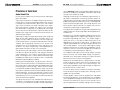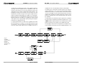
1
CE 4000 © 2001 by Crown Audio, Inc., P.O. Box 1000, Elkhart, IN 46515-1000 U.S.A. Telephone: 219-294-8000. Fax: 219-294-8329. Trademark Notice: Crown ® is a registered trademark of Crown International, Inc. Other trademarks are the property of their respective owners. Some models may be exported under the name Amcron.® Obtaining Other Language Versions: To obtain information in another language about the use of this product, please contact your local Crown Distributor. If you need assistance locating your local distributor, please contact Crown at 219-294-8200. Note: The information provided in this manual was deemed accurate as of the publication date. However, updates to this information may have occurred. To obtain the latest version of this manual, please visit the Crown website at www.crownaudio.com. 127393-2A 3/01 CE 4000 The amp with an Attitude! CE 4000 The amp with an Attitude! Important Safety Instructions Contents 1) Read these instructions. 2) Keep these instructions. 3) Heed all warnings. 4) Follow all instructions. 5) Do not use this apparatus near water. 6) Clean only with a dry cloth. 7) Do not block any ventilation openings. Install in accordance with the manufacturer’s instructions. 8) Do not install near any heat sources such as radiators, heat registers, stoves, or other apparatus that produce heat. 9) Do not defeat the safety purpose of the polarized or grounding-type plug. A polarized plug has two blades with one wider than the other. A grounding-type plug has two blades and a third grounding prong. The wide blade or the third prong is provided for your safety. If the provided plug does not fit into your outlet, consult an electrician for replacement of the obsolete outlet. 10) Protect the power cord from being walked on or pinched, particularly at plugs, convenience receptacles, and the point where they exit from the apparatus. 11) Only use attachments/accessories specified by the manufacturer. 12) Use only with a cart, stand, bracket, or table specified by the manufacturer, or sold with the apparatus. When a cart is used, use caution when moving the cart/apparatus combination to avoid injury from tip-over. Da Rules ...................................................................... 4 Quick Start ................................................................... 6 1 Welcome ............................................................... 8 How To Use This Manual ..................................... 10 Unpacking Your CE 4000 Amplifier ...................... 10 Features .............................................................. 11 Controls, Indicators & Connectors ....................... 12 2 Installation ........................................................... 14 3 Operation ............................................................ 24 4 Crown Pro Information Guides: Balancing the Line .............................................. 29 The Dastardly Duo: Hum and Buzz ..................... 30 Guide to Neutrik Speakon NL4FC Connector Assembly ............................................................ 33 5 Advanced Features and Options: BCA .................................................................... 37 Switching Power Supply with PFC ....................... 37 Crown SST Modules ............................................ 38 Fault Monitoring .................................................. 43 Handle Kit ........................................................... 44 Optional Output Connectors ................................ 44 6 Principles of Operation ........................................ 46 7 Specifications ..................................................... 52 8 Service ................................................................ 57 13) Unplug this apparatus during lightning storms or when unused for long periods of time. 14) Refer all servicing to qualified service personnel. Servicing is required when the apparatus has been damaged in any way, such as power-supply cord or plug is damaged, liquid has been spilled or objects have fallen into the apparatus, the apparatus has been exposed to rain or moisture, does not operate normally, or has been dropped. 15) To reduce the risk of fire or electric shock, do not expose this apparatus to rain or moisture. Page 2 Reference Manual Reference Manual Page 3 CE 4000 The amp with an Attitude! Da Rules 1. Read all safety and operating instructions before operating the CE 4000 amplifier. Follow all instructions carefully and heed any warnings given. 2. Do not drop or spill any foreign object or liquid into the CE 4000 amplifier. Hey! I'm Eric Let me fill you in about your new CE 4000 Amp!! Page 4 3. WARNING: Shock hazard. To reduce the risk of fire or electric shock, do not expose this unit to rain, moisture or splashing. Do not immerse your CE 4000 amplifier in any liquid. Do not operate your amplifier near a pool, bathtub or other standing water (even on a dare). 4. Do not bypass or defeat the grounding or polarization means used on the CE 4000 amplifiers. Make sure all blades on the polarized power plug can be fully inserted into the receptacle or other outlet that will be used with the unit. 5. Your CE 4000 amp should be cleaned only with a dry cloth. 6. Take care of the power cord attached to your CE 4000 amplifier. Avoid situations where your cord might be stretched, pinched, or otherwise abused. Route it to avoid foot traffic. Pay special attention to the cord connector and attachment points. Reference Manual CE 4000 The amp with an Attitude! 7. Do not attempt to service this unit beyond instructions contained in this manual. Refer all servicing to the Crown Service Department. 8. Keep your CE 4000 amplifier away from sources of heat, such as a radiator or oven. Do not cover or surround your amp with material which may retain heat, such as a blanket or curtain. 9. Obtain assistance from qualified service personnel if any of the following occurs: • The power cord or plug has been damaged in any way. • Foreign objects or liquid have fallen into the amplifier enclosure. • The amplifier has been exposed to rain or has been partially or totally immersed in any liquid. • The amplifier has been dropped or the chassis has been damaged. • You notice a marked change in performance, or your CE 4000 amp does not Reference Manual appear to operate normally. 10. CAUTION: Do not locate sensitive, high-gain equipment such as preamplifiers or tape decks directly above or below the unit. If an equipment rack is used, we recommend locating the amplifier(s) in the bottom of the rack and the preamplifier or other sensitive Ke equipment at the top.ep th ese instr uctio n wher e you s can look a t em later ! Lightning Bolt Symbol: This symbol is used to alert the user to the presence of dangerous voltages and the possible risk of electric shock. Exclamation Mark Symbol: This symbol is used to alert the user to make special note of important operating or maintenance instructions found in the reference manual. Page 5 CE 4000 The amp with an Attitude! CE 4000 The amp with an Attitude! Did You Remember To Get Your Speakons®? Quick Start! You’ve waited a long time for this! We know you just can’t wait to crank up your new Crown® CE 4000 amplifier. And you sure don’t want to flip through pages of tech-talk just to find out where the on switch is. So that’s why we provided you with this quick and simple page to get you up and running right away. Just take a few minutes to read through this—no more than five or ten, max—you’ll be glad you did. 1. Make sure the CE 4000 amp and all other equipment is turned off (“O”) before you begin wiring. By the way, the amp power switch is located on the far left side of the front panel. It is off (“O”) when depressed on the left. 2. Mount your CE 4000 amp securely in the rack, or position it on a solid surface. 3. Connect the left and right inputs coming from your mixer, preamp, or processor. You can use either balanced 1/4-inch (6.35-mm) phone, 3-pin XLR or barrier block connectors. You can also choose to run in MONO mode. (See Figure 2.5.)3.2.2 Output Wiring The Fault light blinks a few times, and the “Power” light will glow a bright green to indicate power is on. 8. (Now comes the fun!) Supply input, adjust amp levels and enjoy. 9. You can check the green signal light to verify input, if necessary. CAUTION: Excessive output levels may toast your speakers. Crown’s CE 4000 amplifiers have such low distortion, you may not realize the actual level being reached until it’s too late. Please exercise caution and drive your speakers responsibly (or at least warn your neighbors!). Typical Stereo Hookup WARNING: Output terminals marked with the symbol are dangerous when live. External wiring connected to these terminals requires installation by an instructed person, or should make use of prebuilt wiring and connectors. 4. Connect the output wiring (left and right speakers). You can use your choice of Neutrik® Speakon® NL4FC, banana, spade lug or bare wire, depending on the output connector configuration you have chosen. 5. Connect your CE 4000 amp and other equipment to your power source. 6. Turn on your mixer, preamp, signal processor, or any other equipment in your system EXCEPT your CE 4000 amplifier. (Remember: the best is worth waiting for.) 7. Make sure the Channel 1 and Channel 2 level (volume) controls on your CE 4000 amplifier are turned all the way down (counterclockwise), then flip the power switch on (“I”). Note: Page 6 Reference Manual Reference Manual Page 7 CE 4000 The amp with an Attitude! CE 4000 The amp with an Attitude! Fig. 1.1 The CE 4000 Amplifier 1 Welcome Thanks for buying this CE 4000 amplifier. Here at Crown, we appreciate your support, and we think you’ll find that you’ve also done yourself a favor by choosing Crown. You see, CE 4000 amplifiers have been engineered from the bottom up for top-notch performance and unmatched reliability. Designed using Crown’s patented, award-wining BCA® (Balanced Current Amplifier) engineering, the CE 4000 provides superior power output, increased efficiency, legendary Crown sound and extraordinary reliability. With typical output power at 3,600 watts*, the CE 4000 not only handles but excels at handling 2-ohm loads. In repeated stress tests, the CE 4000 continued to perform at levels 12 dB into clip, long after the competition had shut down. easily add a sub-bass system. Additional signal control is available via Crown’s optional SST (System Solution Topologies) modules, which offer a wide variety of active crossover configurations.** Your choice of optional output connectors is also available: Neutrik Speakon® plus 5-way binding post, 5-way binding post plus barrier strip, or dual Neutrik Speakon. Weighing in at a mere 33.3 pounds, the CE 4000 is easy to transport and set up. What’s more, Crown’s enhanced, switchmode power supply (featuring power factor correction) results in a universal power supply, so you can plug it in anywhere. And with the lowest cost per watt of any amp in its class, the CE 4000 is the obvious choice for serious musicians everywhere. Designed for the utmost in flexibility, the CE 4000 features selectable on-board high- and low-pass filter sets, so you can * 3,600 watts in Bridge-Mono mode at 4 ohms, 1,800 watts per channel at 2 ohms. See the Specifications Section for details. Page 8 Reference Manual ** Your amplifier may have come already outfitted with a factory-installed SST module, or your choice of SST modules can be added to an existing amplifier by an authorized Crown Service Center. For more information on factory-installed SST modules, please refer to the Crown SST Crossover Reference Manual included in your literature package. Reference Manual Page 9 CE 4000 The amp with an Attitude! How to Use This Manual CE 4000 The amp with an Attitude! Features This manual will help you correctly install, set up and operate your CE 4000 amplifier, including mounting, mode selection, standard input and output wiring, advanced features and options setup, and typical operation. Please be sure to read all instructions, warnings and cautions. If your amplifier came equipped with an optional Crown SST crossover module, please refer to the SST Crossover Reference Manual included in your literature package for information on amplifier setup. For your protection, please send in the warranty registration card today. And save your bill of sale—it’s your official proof of purchase. Unpacking Your CE 4000 Amp Please unpack and inspect your amplifier for any damage that may have occurred during transit. If damage is found, notify the transportation company immediately. Only you can initiate a claim for shipping damage. Crown will be happy to help as needed. Save the shipping carton as evidence of damage for the shipper’s inspection. We also recommend that you save all packing materials so you will have them if you ever need to transport the unit. NEVER SHIP THE UNIT WITHOUT THE FACTORY PACK. * See Specification section for details. Page 10 Reference Manual Reference Manual Page 11 CE 4000 The amp with an Attitude! CE 4000 The amp with an Attitude! Controls, Indicators & Connectors Fig. 1.2 The Big Picture: Controls, Indicators & Connectors* * Shown with standard input module and Neutrik Speakon® / 5-way binding post output connectors option. Page 12 Reference Manual Reference Manual Page 13 CE 4000 The amp with an Attitude! 2 Installation Follow these instructions for a detailed explanation of CE 4000 installation procedures and options. If you just want to get up and running as quickly as possible, see the Quick Start section on page 6. 2.1—Begin with the amplifier turned off and disconnected from the power receptacle. The CE4000 power switch is located on the left side of the front panel; it is off (“O”) when depressed on the left. Equipment that will be connected to the inputs of the amplifier (such as mixers,equalizers or signal processors) should also be turned off. 2.2—Mount the amplifier. Your CE 4000 amp can be mounted in a standard, 19-inch (48.3-cm) equipment rack, or it can be simply stacked with other equipment. The CE 4000 amp is provided with a convenient 3-foot (1-meter) power cord to minimize excess cordage when installed in a rack. Do not use extension cords. Properly wired power outlets must be provided close to the mounted amplifier. If you choose to mount your amp in a rack, you should secure the back of the rack as well as the front. Securing the amp at both front and rear will assure that the amp stays in place, even when the rack is transported or accidentally dropped (which we know never happens). Fig. 2.1 Mounting Dimensions CE 4000 The amp with an Attitude! 2.3—Set the mode switch. Make sure your amplifier is turned off (“O”) before moving this switch. The Mode switch should be in the “Stereo” position when you’re running in Stereo Mode. Stereo Mode allows independent inputs on the left and right channels to feed separate speakers at the output. It’s the configuration typically chosen for everyday audio applications. Fig. 2.2 Mode Switch Turn the Mode switch to “Bridge-Mono” to have a single input that feeds to a single output with twice the voltage of Stereo Mode. Use this configuration if you want to give up stereo capabilities in order to drive your speakers louder. Note that the wiring will also need to be adjusted for this configuration—that includes both input and output wiring. See Step 2.5 (Connecting the Outputs) and Figure 4.8 later in this section for correct wiring when running in Bridge-Mono mode. 2.4—Connect the inputs of the CE 4000 amp to your mixer, equalizers, or signal processors ahead of the amp. Three types of balanced input connectors are provided, allowing you to choose barrier strip,1/4-inch (6.35-mm) phone or 3-pin XLR connectors.* You can also choose to use either balanced or unbalanced wiring. (See the information on “Balancing the Line” in the Crown Pro Information Guide section for an explanation of balanced vs. unbalanced wiring.) If the Mode switch is in “Bridge-Mono” position, only the Channel 1 input connectors should be used. *Optional SST crossover may provide other input connector options. Page 14 Reference Manual Reference Manual Page 15 CE 4000 The amp with an Attitude! Fig. 2.3 Typical Input Wiring CE 4000 The amp with an Attitude! Output Wiring Tips 1. This amp offers Neutrik Speakon® connectors to minimize wiring mistakes.* We also encourage you to choose carefully when selecting speaker enclosure connectors. 2. To prevent possible short circuits, wrap or otherwise insulate exposed loudspeaker cable connectors. 3. Do not use connectors that might accidentally tie conductors together when making or breaking the connection (for example, a standard, 1/4-inch (6.35-mm) stereo phone plug). 4. Never use connectors that could be plugged into AC power sockets. Accidental AC input will be an electrifying experience for your equipment. But you will find out real quick if your speakers are any good at 60 Hz. symbol WARNING: Output terminals marked with the are dangerous when live. External wiring connected to these terminals requires installation by an instructed person, or should make use of prebuilt wiring and connectors. 2.5—Connect the outputs of the CE 4000 amp to your loudspeakers. For Stereo mode, refer to the Stereo Output Hookup diagram (Figure 2.4). For Bridge-Mono mode, refer to the Bridge-Mono Output Hookup diagram (Figure 2.5). Input Wiring Tips 1. For all input connectivity, use shielded wire only. Cables with a foil wrap shield or a high-density braid are superior. Cables with a stranded spiral shield, although very flexible, will break down over time and cause noise problems. 2. Try to avoid using unbalanced lines with professional equipment. If you have no choice, keep the cables as short as possible. (Refer to the information on “Balancing the Line” in the Crown Pro Information Guide section.) 3. To minimize hum and crosstalk, avoid running low-level input, high-level output and AC power feeds in the same path. Try to run differing signal paths at 90° to one another. If you must use a common path for all cables, use a star-quad cable for the low-level signals. 4. When changing input connectors or wiring, turn the amplifier level controls all the way down (counter-clockwise) before connecting or disconnecting input plugs. 5. When changing output connections, turn the amplifier level down and the AC power off to minimize the chance of short-circuiting the output. Page 16 Reference Manual 5. Avoid using connectors with low current-carrying capacity, such as XLRs. 6. Do not use connectors that have any tendency to short. 7. To maintain good bass response, use the lowest DC resistance cable you can afford which will terminate safely in your connectors. You will need two high-quality speaker cables terminated with the appropriate connectors to fit your CE 4000 amp at one end and your speakWIRING SPEAKON® ers at the other end. Output Connector opOUTPUT CONNECTORS: tions for the CE 4000 ampflifier include See the Crown Pro InformaNeutrik Speakon® plus 5-way binding tion Guide section of this post, 5-way binding post plus barrier strip, manual. or dual Neutrik Speakon® outputs. If you prefer, you can wire custom speaker cables to fit your exact requirements. For detailed instructions on wiring and assembling the Neutrik® Speakon® NL4FC connectors, see the “Guide to Neutrik Speakon NL4FC Connector Assembly” in the Crown Pro Information Guide section of this manual. You may also choose to connect to the amplifier using banana, spade lugs, or bare wire connectors depending on the output options specified for your amplifier. IMPORTANT: Custom wiring should only be installed by qualified personnal. * Some optional output configurations may not offer Neutrik Speakon® connectors. Reference Manual Page 17 CE 4000 The amp with an Attitude! 2.6—Check to make sure that adequate ventilation has been provided. Even though this amplifier has some of the most efficient heat sinks in the marketplace, it must be able to breathe. So make sure that the front vents are never blocked and that the exhaust fan (out the back) notblocked or covered by cables. An amplifier running at high sound pressure levels into low-impedance loads will typically put out lots of hot air, so make sure it can go somewhere. CE 4000 The amp with an Attitude! Cooling Tips If you allow spaces between pieces of equipment in your rack, make sure you block the front with blank, solid (not perforated) panels. This will allow the rack to act as a chimney with hot air exhausting at the top, not recirculating between adjacent amplifiers. If you are running your equipment in dusty or dirty environments, it is advisable to pre-filter the air using industrial furnace filters. These filters can be taped or fastened to the front of the equipment rack, ensuring a clean air supply through a large surface area that will require minimum maintenance. 2.7—Check once more to make sure the amplifier has been set up correctly. Then follow the steps in the Operation section to operate the amplifier. Page 18 Reference Manual Reference Manual Page 19 CE 4000 The amp with an Attitude! CE 4000 The amp with an Attitude! Fig. 2.4 Stereo Hookup— Two Stacks, One Amp, Stereo In, Stereo Out Page 20 Reference Manual Reference Manual Page 21 CE 4000 The amp with an Attitude! CE 4000 The amp with an Attitude! Fig. 2.5 DJ Application Note: Mono hookup requires custom wiring on Neutrik connectors. See Figure 4.8 for more information. Page 22 Reference Manual Reference Manual Page 23 CE 4000 The amp with an Attitude! CE 4000 The amp with an Attitude! 3 Operation Figure 3.1 Front Panel Indicators & Controls Your CE 4000 amp is really very easy to operate, once it has been properly configured. If your amplifier has not yet been set up or configured, please refer to the installation instructions found in Section 2 of this manual, or consult with your system installer. Follow these steps when first turning on your amplifier: 1 Turn down the level of your audio source. For example, set your mixer’s volume to “ ” off. ¥ 2 Turn down the amplifier’s level controls (counter-clockwise to “ ”). ¥ 3 Turn the power switch to the on (“I”) position. The power indicator beside the switch will turn on. 4 After the Power light turns on, test the operating range of your input by turning up the level of your audio source to the highest possible operating level before distortion. You should notice the green signal indicators glowing on your amplifier. 5 turn up the level controls on the front of the amplifier until the maximum desired loudness or power level is achieved. Be prepared for astounding output! S-L-O-W-L-Y 6 Turn down the level of your audio source to its normal range. Controls & Indicators Refer to the following for information on how to operate and read your CE 4000 controls and indicators. See Figures 3.1 and 3.2 for location of controls and indicators. Page 24 Power Switch: The power switch is conveniently located on the front panel so you can easily turn the amplifier on (“I”) or off (“O”). When the switch is depressed left, the amp is off. Fault Indicators: Two red LEDs (one for each channel) are located on the front panel. The Fault Indicators are normally OFF, but will blink under five different conditions: Note that dangerous voltages may still be present in the amplifier even when the power switch is in the off (“O”) position. Before moving the amplifier or making any wiring or installation changes, it is important to also disconnect the power cord from the amplifier or power source. 1. When the amplifier is first powered up, until the unit is ready for operation. Reference Manual 2. If the heatsinks reach a temperature above normal working limits. Reference Manual Page 25 CE 4000 The amp with an Attitude! CE 4000 The amp with an Attitude! Figure 3.2 Back Panel Controls 3. If the transformer thermal protection circuit is activated. 4. If amplifier output wires develop a short-circuit. 5. Should the amplifier output stage become non-operational. The fault status of the amplifier can also be monitored remotely by attaching a signalling device to the Fault jack located on the amplifier back-panel. See the Advanced Features and Options section of this manual for more information on fault monitoring and suggestions for signalling device circuity. Some fault conditions may cause the output of the amplifier to be muted. Clip Indicator: Two red LEDs (one for each channel) are located on the front panel. The Clip indicators turn on when distortion is audible in the amplifier output. Signal Indicator: Two green LEDs (one for each channel) are located on the front panel. Unlike some of our other amplifiers, the Signal indicators on the CE 4000 amplifier lluminate when a signal (>–40 dBm) is present at the INPUT of the amplifier for that channel. Because these indicators receive the signal before the level controls, they can be used to troubleshoot wiring problems within a system. If the Signal indicator for a channel is not lit, no signal is reaching the amplifier on that channel. Power Indicator: A green LED is located on the front panel. The Power indicator lights when your CE 4000 amp has been turned on and has power. Level Controls: Two rotary level controls (one for each channel) are located on the front panel. Use these controls to adjust each channel’s output. To decrease the level, rotate the control counter-clockwise (to “ ”). To increase the level, rotate it clockwise (to “0”). ¥ Input Sensitivity Switch: A three-position Input Sensitivity switch is located on the back panel near the input connectors. Your amplifier is shipped from the factory with this switch set to the 1.4-V position. At this setting , a 1.4-V input signal will drive the amplifier to full power into an 8-ohm load when the level controls are turned to maximum. This translates to an amplifier gain of 33.8 dB or +4 dBu—a level at which most professional equipment operates. If required, the Input Sensitivity switch can be moved to the 3.46-volt (26-dB) position, so that the amplifier provides a fixed voltage gain of 20 (or 26 dB: 1 volt in, 20 volts out). This setting works best with output levels of +10 dBu (2.5 volts RMS) or more. Some brands of DJ mixers, in particular, have output levels in this range. You can also choose the 0.775-volt setting for a gain of 39.0 dB. This setting operates with a lower-level output and so may be appropriate for use with consumer-grade CD players and similar items. Consult the owner’s manual of your input device for recommended sensitivity settings. Selecting the correct sensitivity will allow your equipment to operate at its optimum level and improve the signal-to-noise of the system. Page 26 Reference Manual Reference Manual Page 27 CE 4000 The amp with an Attitude! CE 4000 The amp with an Attitude! Mode Switch: This two-position switch, located on the back panel, allows the selection of either Stereo or Bridge-Mono mode of operation. 4 Crown Pro Information Guides Stereo mode provides identical power output to each of the two amplifier output channels. Bridge-Mono Mode combines the two amplifier output channels into a single mono channel with twice the voltage of a single stereo channel. This means the output will be much more powerful! It does this by bridging the outputs, and it requires special output wiring. Do NOT select Bridge-Mono mode without first making sure the amplifier has been wired in a Bridge-Mono configuration. For more information on wiring for Bridge-Mono mode, see the Installation section of this manual, or consult your system installer. A balanced audio circuit typically will have both positive (+) and negative (–) legs of the circuit isolated from the ground circuit. These balanced legs exhibit identical impedance characteristics with respect to ground, and may also carry the audio signal at the same level, but with opposite polarities. This results in a line that offers excellent rejection of unwanted noise. When Bridge-Mono Mode is selected, only the Channel 1 Level control and the Channel 1 Signal LED will work. If the Channel 2 input is wired, the Channel 2 Level control should be turned to “¥” (counter/anti-clockwise) to prevent distortion. ÿ CH1 and CH2 Filter Switches: A three-position low-pass and a four-position high-pass filter switch for each channel are located on the back panel below the input and output modules. Low-pass filter is switchable among settings for Flat, 80 Hz and 100 Hz, with a 24-dB per octave rolloff. Highpass filter is switchable among settings for Flat, 30 Hz, 40 Hz, and 50 Hz, with an 18-dB per octave rolloff. Fault Jack: This RJ11 jack (which looks like a phone jack) is located on the back panel. By attaching a signalling device to the Fault jack, you can monitor the amplifier’s Fault status from a remote location. See the Advanced Features and Options section of this manual for more information on fault monitoring and suggestions for signalling device circuitry. Balancing the Line BALANCED UNBALANCED GND 1 1 – + 3 2 FROM SOURCE INPUT SHIELD 3 2 + FROM SOURCE INPUT + Fig. 4.1 Balanced & Unbalanced Input Wiring + – SHIELD SHIELD On the other hand, an unbalanced circuit usually holds one leg at ground potential, while the second leg is “hot.” Unbalanced line is less expensive, but is much more susceptible to noise, and is not usually used in professional applications. For the cleanest signal, without unwanted hum and buzz, balanced line is always recommended. It is especially helpful if you have a long cable run (over 10 feet (3 m)), since noise is easily introduced into long, unbalanced lines. 1/4 inch (6.35 mm) Tip = Ring = Sleeve = XLR + – = Pin 2 = Pin 3 = Pin 1 Fig. 4.2 Polarity Conversions Refer to Figure 4.2 for proper pin assignments for both ¼ inch (6.35-mm) and 3-pin XLR balanced audio wiring. Page 28 Reference Manual Reference Manual Page 29 CE 4000 The amp with an Attitude! CE 4000 The amp with an Attitude! Fig. 4.3 Balanced Input Wiring Hum and Buzz Tips 1. It is imperative that all of your electrical equipment share the same power ground reference. 2. Unless you are interfacing to a microphone, the shield of the cable should only be connected at one end. (See Fig.4.3) 3. Do not pass signal ground between electrical components in a grounded source system. 4. If you wish to avoid ground loops, it doesn’t matter if you lift the input or output signal ground for your system topology, just be consistent. Personally I prefer to lift the input signal ground and it has always been successful...so far! 5. NEVER use a ground lift adapter to lift the power ground on a 3-wire AC cord; this is not its intended purpose. It is better to have it SAFE than SILENT!! Look for the true source of the noise. 6. Even when interfacing to an unbalanced load, it is preferable to use two-conductor shielded cable. 7. Get rid of the lighting company! The Dastardly Duo: Dr. Hum and Mr. Buzz If you have noticeable hum or buzz in your system, you may want to check your cable connections to see if the unwanted noise is being introduced via a ground loop. To determine the proper wiring, first check whether the output from your source is unbalanced or balanced (if you don’t know, refer to the unit’s back panel or instruction manual). If the source is balanced, refer to Figure 4.3; if it is unbalanced refer to Figure 4.4. Next, determine if the source’s power cable is floating (ungrounded, 2-prong) or grounded (3-prong). Finally, if the source is unbalanced, check the type of wiring: twin-lead or single coax. Page 30 Reference Manual Check Figure 4.4 to see if your cable has been wired with the proper shield and ground connection. If the cabling is incorrect, you may be able to avoid the ground loop (and associated hum) by plugging all of your equipment into the same AC circuit (on the same breaker). If this is impractical, you will need to fix the cable to match the appropriate illustration. Or you may want to simply replace the offending cable with a commercially manufactured cable of the appropriate type. Reference Manual Page 31 CE 4000 The amp with an Attitude! CE 4000 The amp with an Attitude! Fig. 4.4 Unbalanced Input Wiring Why Speakon? For amplifiers, the most popular termination device on professional products has been the dual banana (which incidentally was pioneered by Crown with the DC300 model). However, recent regulatory requirements in Europe have outlawed the use of the dual banana plug and forced users to terminate speaker cables with spade lugs or bare ends—an approach that is clearly not advantageous to the customer who wants to reconfigure his system or quickly change out a defective product. It is possible that similar regulatory controls will appear worldwide over the next few years. One solution to this problem is to use the Neutrik® Speakon® connector. Here at Crown, we wanted to develop a system for you that eliminated the need for specialized, time-consuming, interface cables. The major loudspeaker manufacturers have been using Speakon® connectors for the input termination on their products for several years now, so you can be assured of the connector’s reliability in the workplace. With Speakon® connectors, you can plug straight from the amp to the speaker, and start making those great sounds right away. The Speakon® connector meets all known safety regulations. Once wired correctly, the connector cannot be plugged in backwards, causing the type of inverted polarity situations that are common with banana hookups. It will provide a safe, secure and reliable method of interfacing your amplifier to the load. Guide to Neutrik ® Speakon® NL4FC Connector Assembly To custom wire Neutrik Speakon NL4FC connectors, you willl need the following materials: two (2) Neutrik Speakon® NL4FC connectors* plus high-quality two- or four-conductor speaker cable with the appropriate end-connectors to fit the inputs on your speakers, a pair of needle-nosed pliers and a (1.5-mm) Allen wrench or a flat blade screw driver. IMPORTANT: Custom wiring should only be installed by qualified personnal. NOTE: You can purchase the Speakon® NL4FC connectors from your local dealer, or contact NEUTRIK AG, Im alten riet 34, Schaan FL-9494, Furstentum Liechtenstein, 41-75-237-2424, FAX 41-75-232-5393, www.neutrik.com or Neutrik USA, Inc., 195 Lehigh Ave., Lakewood, NJ 08701-4527, 908-901-9488, FAX 908-901-9608, www.neutrikusa.com or Crown Audio, Inc., 1718 West Mishawaka Road, Elkhart, IN 46517-4095, USA, 219-294-8000, FAX 219-294-8329, www.crownaudio.com. Page 32 Reference Manual Reference Manual Page 33 CE 4000 The amp with an Attitude! CE 4000 The amp with an Attitude! To assemble the Neutrik Speakon NL4FC connector, complete the following steps: Fig.4.7 Stereo Output Wiring 1. Slide the bushing (E) and chuck (D) onto the end of the cable as shown in Figure 4.5.* Fig.4.5 Order of Assembly for theNeutrik® Speakon®NL4FC Connector 3b. If the Mode switch is in the “Stereo” position (for stereo configuration), connect the positive (+) and negative (–) leads of each wire to the appropriate Channel 1 and Channel 2 connectors as shown in Figure 4.7. You may use all 4 poles of the Channel 1 output connector to feed both speakers, if you wish. Fig.4.8 Bridge-Mono Output Wiring 2. Strip approximately 3/4-inch (20-mm) of casing from the cable end. Strip approximately 3/8-inch (8-mm) from the end of each of the conductors down to bare wire (C). Fig.4.5 Wiring for the Neutrik® Speakon® NL4FC Connector 3c. If the Mode switch is in the “Bridge” position (for mono configuration), connect the load across the positive (+) terminals of the connector as shown in Figure 4.8. For Bridge-Mono Mode, non-inverting output, Ch1+ is the positive (+) and Ch2+ is the negative (–). 3d. Never short or parallel the output channels of an amplifier to itself or any other amplifier. Fig. 4.9 Connector Assembly: Insert into Connector 3a. Insert each wire into the top of appropriate slot of the connector insert (B) as shown in Figure 4.6. Use a (1.5-mm) Allen wrench or flat blade screwdriver to tighten the side connecting screws. * Your NL4FC connector kit should contain both a black and a white chuck. Use the white chuck for cable with a diameter of 0.25 to 0.5 inch (6.35 to 12.7 mm). Use the black chuck for cable with a diameter of 0.375 to 0.625 inch (9.525 to 15.875 mm). Page 34 Reference Manual 4. Slide the connector insert (B) into the connector housing (A), making sure that the large notch on the outer edge of the insert lines up with the large groove on the inside of the connector housing. The insert should slide easily through the housing and out the other side until it extends approximately 3/4-inch (19-mm) from the end of the housing. (See Figure 4.9.) Reference Manual Page 35 CE 4000 The amp with an Attitude! Fig.4.10 Connector Assembly: Chuck into Connector Housing 5 Advanced Features & Options BCA® 5. Slide the chuck (D) along the cable and insert into the housing, making sure that the large notch on the outer edge of the chuck lines up with the large groove on the inside of the connector housing. The chuck should slide easily into the insert/housing combination until only approximately 3/8-inch (9.5-mm) of the chuck end extends from the back end of the connector as shown in Figure 4.10. BCA® (Balanced Current Amplifier) is Crown’s patented, cutting-edge technology that gets more power out of an amplifier with less waste than was ever before possible. A completely new adaptation of standard amplifier design, Crown’s BCA “switching” amplifier design provides for high output, exceptional reliability and nearly twice the efficiency of typical amplifier designs. While switching designs have been used successfully in other applications, these designs were never before suitable for use in precision, high-power audio amplifier applications. Crown’s BCA technology changes that, with a totally new paradigm for amplifier design that represents the future of professional amplifiers. With their superior efficiency, BCA amplifiers can help to keep your power bills down, while still putting out amazing, bassthumping lows and crystal clear highs. And your Crown BCA amp is tough—easily handling very low (and highly reactive) load impedances, even under extreme conditions. In fact, Crown BCA amps have far out-performed competitive amplifiers in tests where the amplifier was run as much as 12-dB into clip for extended periods of time. Fig.4.11 Connector Assembly: Bushing onto Connector Housing Assembly 6. Slide the bushing along the cable and screw onto the end of the connector combination as shown in Figure 4.11. Note that the bushing features a special locking construction which will prevent disassembly of the NL4FC connector once this cap is tightened into place. Before tightening, you may want to test the connector in a live system to make sure it has been assembled properly. Page 36 CE 4000 The amp with an Attitude! Reference Manual High efficiency, tough robust design and great Crown sound make Crown BCA amplifiers the clear choice for professional musicians everywhere. Switching Power Supply with PFC Crown’s new Switching Power Supply with PFC provides a range of benefits over both non-switching and conventional switching power-supply designs. Reference Manual Page 37 CE 4000 The amp with an Attitude! Typical non-switching power supplies require large, heavy transformers in order to produce the required power at the output stage. These transformers must be large to absorb the substantial waste that occurs when operating at 50 to 60 Hz (standard AC supplied by the power company). By contrast, switching power supplies can operate with a much smaller (and lighter) transformer because they first convert the AC up to a much higher frequency, thereby reducing waste. However, in both non-switching and conventional switching designs, phase differences occur within the power supply due to the inductance of the transformer. This phase difference prevents much of the available power from the AC mains from making its way to the load. PFC, however, compensates for phase differences in the power supply, allowing more true power to be transferred to the amplifier. The result is more power with less waste than any other conventional switching or non-switching design. As an added benefit, PFC also allows the amp to be connected to any common AC line voltage, without converting the power supply. This means that whether you’re running one or two amps on a household circuit or several amps on a power distro, your CE 4000 amplifiier is ready—right out of the box. Crown SST Modules Crown’s optional SST (System Solution Topologies) modules were specially designed to improve the fidelity and versatility of your audio system. They feature a variety of professional signal routing and filtering capabilities, with active crossovers that allow the audio signal to be split and sent to auxiliary amplifiers. Your amplifier may have come with an SST module already factory-installed, or your choice of SST modules can be easily added to the amplifier by any authorized Crown Service Center. Page 38 Reference Manual CE 4000 The amp with an Attitude! Why Biamped? When you use one of Crown’s SST crossover modules to split the power drive to your loudspeaker components, you gain a wide range of advantages, including: 1. Increased gain because the insertion loss of passive crossover networks is eliminated. 2. Consistent power bandwidth: power bandwidth is changed in multiway passive systems if transducers change impedance or vaporize (blow up). 3. Levels can be matched more accurately to the components. 4. Quicker troubleshooting. 5. Improved dynamic range. 6. Better protection of components due to steep 24-dB/octave filters. For information on wiring and configuration of amplifiers equipped with an optional Crown SST crossover module, please refer to the SST Crossover Reference Manual included in your literature package. Refer to the following descriptions for an overview of available Crown SST crossover modules. SST-MX Crossover The SST-MX crossover module features 24-dB/octave LinkwitzRiley tuned filters and stereo sub-bass outputs for biamp operation of subs. See Figure 5.1 for SST-MX block diagram. Features of the SST-MX crossover include: • Stereo biamp. • 100-Hz fixed crossover • 24-dB/octave Linkwitz-Riley tuned filters. Reference Manual Page 39 CE 4000 The amp with an Attitude! CE 4000 The amp with an Attitude! Features of the SST-SX crossover include: • Neutrik® Combo ¼-inch (6.35-mm) and XLR input jacks. • Barrier block balanced outputs. • Mono-summed sub-bass output. • Optional high-pass filter bypass on amplified outputs adapts system for full-range use. • 24-dB/octave Linkwitz-Riley tuned filters. • Crossover switchable between 80 and 120 Hz. • Neutrik® Combo ¼-inch (6.35-mm) and XLR input jacks. • Male 3-pin XLR outputs • Optional high-pass filter bypass on amplified output adapts system for full-range use. + CH2 SUB OUT Fig. 5.2 SST-SX Crossover Block Diagram Page 40 100 Hz LP 24 dB/oct. slope IN 100 Hz HP 24 dB/oct. slope BYPASS BYPASS + 1 3 2 CH2 CH1 2 1 3 – – + 100 Hz LP 24 dB/oct. slope 100 Hz HP 24 dB/oct. slope IN 100 Hz HP HOST AMPLIFIER CH2 INPUT HOST AMPLIFIER CH1 INPUT – – + + TB – + – 100 Hz LP Fig. 5.1 SST-MX Crossover Block Diagram CH1 SUB OUT SST-SX Crossover The SST-SX crossover module features 24-dB/octave LinkwitzRiley tuned filters and mono-summed sub-bass outputs for biamp operation of subs. See Figure 5.2 for SST-SX block diagram. Reference Manual Reference Manual Page 41 CE 4000 The amp with an Attitude! SST-SBSC (Summed Bass Stereo Crossover) Module Crown’s advanced SST-SBSC module offers ten user-specified crossover frequencies, CD horn EQ and summed subbass output for driving subs (see Figure 5.3 for block diagram). The SST-SBSC offers the following features: • Stereo biamp. • 12-, 18- and 24-dB (Linkwitz-Riley) / octave filters. • CD horn equalization. • Mono summing of sub-bass output for driving subs. Crown plans to release additional accessory plug-in modules offering a range of advanced features and capabilities. Watch for new releases. CE 4000 The amp with an Attitude! Fault Monitoring The Fault (RJ11) jack, which looks like a telephone plug, is located on the back of your CE 4000 amplifier. It gives you an easy way to remotely monitor the amplifier’s fault status. To set up a circuit that will cause an LED to light whenever a fault status occurs, you can simply use the suggested circuit shown in Figure 5.4. When using this circuit, the LED will glow whenever the amplifier is in one of four states: a channel’s heatsink has reached its temperature limit, the transformer has reached its temperature limit, the amplifier has just been turned on and is in its turn-ondelay mode, or the amplifier is turned off. Figure 5.3 Block Diagram for Crown’s SST-SBSC Page 42 Reference Manual Reference Manual Page 43 CE 4000 The amp with an Attitude! Fig. 5.4 Fault Status LED Circuitry CE 4000 The amp with an Attitude! (model CE4C) connectors installed in your amplifier in place of the standard Neutrik Speakon® plus 5-way binding post outputs (model CE4D) at time of ordering. See Figures 5.6 and 5.7. For information on adding optional output connector modules to an existing CE 4000 amplifier, please contact Crown Technical Support. Fig. 5.6 Model CE4E Dual Neutrik Speakon® Output Connectors If you choose to design your own circuit to interface this signal to your system, note that this RJ jack is polarity sensitive. Pin 2 must be grounded, and Pin 5 must be supplied with a positive voltage pull up (positive with respect to ground). Refer to Figure 5.5 for RJ jack pin assignments.* The maximum signal that can be exposed to the fault jack is 35 VDC and 10 mA. Best results are obtained with 10 mA LEDs. Fig. 5.5 RJ Jack Wiring and Pin Assignments Fig. 5.7 Model CE4C 5-way Binding Post plus Barrier Strip Output Connectors Handle Kit Handles complement your amplifier’s appearance, aid in transportation, and the placement in or removal from racks. They are available from Crown’s Sales Department. Optional Output Connectors For added system flexibility, Crown offers optional output connector configurations for your CE 4000 amplifier. If you prefer, you can choose to have dual Neutrik Speakon® output connectors (model CE4E) or 5-way binding post plus barrier strip * The mating connector for the CE 4000’s RJ11 jack contains 4 contact pins in a 6-slot case, as shown. For additional information please contact your local dealer or Crown Technical Support. Page 44 Reference Manual Reference Manual Page 45 CE 4000 The amp with an Attitude! Principles of Operation mance. Warning: Details of closed loop amplifier design are beyond the scope of this description and if discussed, would surely put most readers to sleep! Audio Signal Path For the sake of simplicity, only channel one of the audio signal path is described. Signal is presented to the CE 4000 through one of three connectors when using the standard input module. Each channel is outfitted with a balanced XLR / phone jack, and a barrier strip. These connectors are wired in parallel, which allows daisy chaining when needed. The signal is then converted from balanced to unbalanced in the Balanced Input Stage where it also receives RFI protection. Signal then flows into the Variable Gain Stage where the front panel level controls are allowed to affect the gain. Following this stage, the signal goes through a gain stage that allows for the various positions of the sensitivity switch. The signal is then put under the control of a full-time compressor circuit comprised of a symmetrical window detector, a buffer amplifier, and the gating op amp which uses several small components to set the compressor’s attack and decay characteristics. The actual compressing is accomplished by an opto-isolator that affects the gain in the signal path. The signal then is passed through a series of switchable filters that allow the signal to be low-pass and high-pass filtered at various frequencies. The switches are located at the back panel. The low-pass filter is a fourth-order Linkwitz-Riley type (24-dB/octave rolloff) and the high-pass filter is a third-order Butterworth type (18-dB/octave rolloff). Following the switchable filters, the signal enters a 32 kHz 7th Order Gaussian Low-Pass Filter. This filter prevents the modulator stage and the output filter (both described below) from receiving signals that are too high. Without the 32 kHz filter, the modulator would be unable to process signals that are too high and the output filter would not yield the proper frequency response behavior. The Gaussian filter type is unique in that it has minimal ringing and excellent phase response so even a high-order filter such as this one does not adversely affect the sonic excellence of the product. The signal next enters the main amplifier error amp where it is mixed with a small portion of the output voltage and current in such a way as to control the amplifier’s overall output perforPage 46 CE 4000 The amp with an Attitude! Reference Manual Following the error amp is the modulator stage where the audio signal is compared to an extremely accurate 250 kHz triangle waveform. Comparators output a Pulse Width Modulated (PWM) string of pulses at 250 kHz that vary in width depending on the level of the input signal. These strings of pulses, one for the positive side and one for the negative side, are connected to the output stage via optocouplers. The signals from the optos are then passed to gate drivers that amplify the pulses to the level required to drive output devices. The driven ou tput devices are now able to produce PWM pulses that have an output voltage from the negative high-voltage rail (-Vcc) to the positive high-voltage rail (+Vcc). This output voltage is always the same (2 * Vcc) but the width of the pulses is still dependent on the level of the input signal. The positive and negative output PWM pulses then pass through inductors and are summed together. Summing the output signals through inductors reconstructs the audio signal, amplified to the desired level. There is a small amount of ripple on the output that is at double the switching frequency (500 kHz). The amplified audio signal is then passed through an output filter that removes the residual ripple voltage. The power is delivered to the load cables through the output connector panel which consists of one of several options. Protection for the output devices is performed by a very precise pulse-by-pulse current limiter circuit that operates each time the output devices switch. The current limiting is “flat” meaning that, regardless of the output voltage, the output current always limits at a certain value. The turn-on delay circuitry functions to keep the modulators turned off (which keeps the outputs from switching) until all supplies are up and stable. Thermal probes monitor Heatsink temperatures and power transformer temperature. As the temperatures rise, the probes send a proportional voltage to the fan control circuit and the Thermal Limit Control (TLC) circuit. The fan normally runs at very low speed when the amplifier is idling or when it is being Reference Manual Page 47 CE 4000 The amp with an Attitude! used for low to moderate duty work. If the amplifier is delivering large amounts of power into low impedance loads, the heatsinks or transformer may heat up enough to increase the speed of the fan to medium and possibly to high speed. If the temperature continues to increase, the TLC circuit uses the compressor to reduce the gain of the input stage and thus reduce the power dissipated by the amplifier. As a further protective measure, if the temperature continues to rise (due to blocked airflow for example), the amplifier will stop running and keep the fan on high speed to quickly bring the temperature back to an operational level. If a signal presented at the input of the amplifier will not be passed through to the output, the Fault LED will blink to get your attention. The turn-on delay, for example, will cause each channel’s LED to blink because the amplifier remains in CE 4000 The amp with an Attitude! standby for a few seconds before it allows audio output. A modular jack is mounted on the back panel (same type as used on telephones). Pins 2 and 5 are connected to an optoisolator that is always in a low-resistance state whenever the unit is on and happy. Should a fault be detected or should the amplifier lose AC power, the opto-isolator will change to a high resistance, allowing the user to remotely detect the status of the amplifier. The Signal Presence Indicators tap the signal chain just before the level controls and prior to the power amplifier chain. They are not amplifier output indicators and should only be used to indicate the presence of signal to the amplifier front end. The Clip light is driven from the output of the compressor circuitry and lights to indicate the onset of audible distortion. The Fig. 6.1 CE 4000 Amplifier Block Diagram (Shown with Standard Input Module) Page 48 Reference Manual Reference Manual Page 49 CE 4000 The amp with an Attitude! Power LED is driven from the low-voltage supply. Power Supply Operation AC power enters the amplifier through a power cord equipped with an IEC (unplugable) connector. It then is passed through the EMI filter. Circuits that use switching technology will normally send a small amount of high-frequency noise back down the power cord and into the power distribution system. This noise must be removed in order to sell the unit in certain parts of the world. Since the CE4000 is a worldwide product, the EMI filter removes this noise so that it does not exit the box. The power then enters the Power Factor Correction (PFC) Boost stage. This stage is what allows the CE4000 to be plugged into any outlet in the world without any modifications to the amplifier. The PFC stage uses switching power supply technology to take whatever AC line voltage comes in, convert it to DC and boost it to 400 Volts. The circuit also uses intelligence to draw the current from the line sinusoidally and in phase with the line voltage. This reduces the load on the power companies and also allows the amplifier to pull more peak power from the power source (the outlet). The power is drawn in small amounts 62,500 times each second and is used to provide power to the isolation stage and to fill the large energy reservoir capacitors. The power then goes to the “buck” isolation stage. This stage Page 50 Reference Manual CE 4000 The amp with an Attitude! takes the 400 Volt PFC voltage and, again using switching power supply technology, converts it down (“bucks” it down) to the level needed to power the audio output stage. The isolation stage also satisfies a safety requirement by providing isolation, using a transformer, between the AC mains power and the power that is delivered to your speakers. The isolation stage moves power 125,000 times each second from the primary to the secondary to power the audio output stage and keep its large energy reservoir capacitors full. In order to keep the power supply controllers, protection circuits, and the audio signal path components powered, another switching power supply is used, this one also running at 125 kHz. This one is also a “buck” type supply in that it takes voltage from the 400 Volt PFC bus and converts it down to the low voltages needed. This circuit also uses a transformer to provide safety isolation. Like the audio signal path parts of the amplifier, there are many ways that the power supply protects itself. Part of the start-up time delay mentioned above occurs while the power supply is ramping up all of its voltages (soft-start) so that large inrush currents are avoided. Current limiters and over-current detectors are used to protect the power supply output devices. The power supply will also detect severe brownouts and shut off the supply until the brown-out is over if the line voltage is drastically less than normal. Reference Manual Page 51 CE 4000 The amp with an Attitude! 7 Specifications CE 4000 The amp with an Attitude! Damping Factor: Greater than 1000 from 10 Hz to 400 Hz.* Note: All measurements are in Stereo mode with 8-ohm loads and an input sensitivity of 26-dB gain at 1-kHz rated power unless otherwise specified. Power Crosstalk: Better than 50 dB below rated power, 20 Hz to 20 kHz. Common Mode Rejection (CMR): Better than 70 dB from 20 Hz to 1 kHz. Output Power: (see Figure 7.1). DC Output Offset (Shorted Input): ±10 mV. Load Impedance: Safe with all types of loads. Rated for 2, 4 and 8 ohms in Stereo mode, 4 and 8 ohms in Bridge-Mono mode. Controls & Connectors Voltage Gain to 1-kHz, 8-ohm rated output: 39.0-dB gain at 0.775-volt sensitivity; 33.8-dB gain at 1.4-volt sensitivity; 26-dB gain at 3.46-volt sensitivity. Power: An on/off rocker switch located on the front panel. Required AC Mains: 50/60 Hz , 100-240VAC (±10%). AC Line Current, 100 Volts: 8.5 A; 120 Volts: 7.1 A; 230-240 Volts: 3.7 A; At Idle: Amp draws no more than 140 watts. AC Line Connector: 15A IEC Connector with Country Specific Cord and Plug. Performance Frequency Response: ±0.25 dB from 20 Hz to 20 kHz at 1 watt (See Figure 7.2). Phase Response: ±15 degrees deviation from linear phase from 20 Hz to 20 kHz at 1 watt. Signal to Noise Ratio, A-Weighted, 20 Hz to 20 kHz: Better than 102 dB below rated 1-kHz power; Total Harmonic Distortion (THD): 1-kHz rated power, 0.5% or less THD from 20 Hz to 20 kHz. Intermodulation Distortion (IMD): (60 Hz and 7 kHz at 4:1) Less than 0.5% at rated power to 30 dB below rated power at 8 ohms. Level: A detented rotary level control for each channel located on the front panel. Mode: Turn power off before switching. A two-position switch located on the back panel below the input connectors which, when turned to stereo, operates the amplifier as two independent channels. When “Bridge-Mono” mode is selected, the amplifier bridges the two output channels for twice the output voltage. Sensitivity: A three-position switch located on the back panel next to the Mode switch. Switchable among 0.775 volts or 1.4 volts for full output into an 8-ohm load (default setting), or 3.46 volts for a fixed voltage gain of 26 dB. Fault Jack: A back-panel RJ11 jack that may be remotely monitored to signal amplifier Fault condition. An LED or other signalling device (not supplied) may be used. Filter Switches: Low Pass: A three-position switch for each channel located on the back panel below the input and output modules. Switchable among settings for Flat, 80 Hz and 100 Hz. Filter rolloff is 24-dB per octave. High Pass: A four-position switch for each channel located on the back panel below the input and output modules. Switchable among settings for Flat, 30 Hz, 40 Hz and 50 Hz. Filter rolloff is 18-dB per octave. Indicators Signal: A green LED for each channel which flashes when a very low-level signal (>–40 dBm) is present at input. May be used for troubleshooting cable runs. * Measured using binding-post output connectors. Page 52 Reference Manual Reference Manual Page 53 CE 4000 The amp with an Attitude! Clip: A red LED for each channel which turns on when distortion becomes audible in the amplifier output. Fault: Normally off, this red indicator will blink under five different conditions: 1. When the amplifier is first powered up, until the unit is ready for operation. 2. If the heatsinks reach a temperature above normal working limits. 3. If the transformer thermal protection circuit is activated. 4. If amplifier output wires develop a short-circuit. 5. Should the amplifier output stage become non-operational. This circuit may be monitored remotely by plugging a simple switching circuit using an LED or other signaling device into the back-panel RJ11 (Fault) jack. Under some conditions, the output of the amplifier will be muted. Power: A green LED that turns on when the amplifier has been turned on and has power. Input/Output Input Connector (standard module): One Neutrik Combo connector for each channel which features a balanced ¼-inch (6.35-mm) phone jack and a 3-pin female XLR connector, in parallel with a barrier strip termination. ® CE 4000 The amp with an Attitude! Output Signal, Stereo: Unbalanced, two-channel; Bridge-Mono: Balanced, single-channel. Channel 1 controls are active; Channel 2 should be turned down. Wiring Configuration: (see Figure: 7.3). Protection CE 4000 amplifiers are protected against shorted, open or mismatched loads; overloaded power supplies; excessive temperature, chain destruction phenomena, input overload damage and high-frequency blowups. They also protect loudspeakers from input/output DC, large or dangerous DC offsets and turn-on/turn-off transients. Construction Rugged steel chassis is formed into a durable package any stagehand could love. Coated with environmentally friendly powder for long life and ease of maintenance. Cooling: Proportional-speed fan-on-demand. Dimensions: EIA Standard 19-inch rack mount width (EIA RS310-B), 5.25-inch (13.34-cm) height and 16.25-inch (36.56cm) depth with additional 1-inch rear rack ears. Weight: The CE 4000 net weight is 33.3 pounds (15.1 kg). Shipping weight is 39.3 pounds. Input Stage: Input is electronically balanced and employs precision 1% resistors. Input Impedance: Nominally 20 k ohms, balanced. Nominally 10 k ohms, unbalanced. Input Sensitivity: 0.775 volts or 1.4 volts for standard 1-kHz power, or fixed 26-dB gain. Output Connectors: Three options available: Four (4) Neutrik® Speakon® NL4MP (mates with NL4FC) output connectors; (2) 5-way binding posts in parallel with two (2) Speakon® connectors; or barrier strip outputs in parallel with two (2) 5-way binding posts. Page 54 Reference Manual Reference Manual Page 55 CE 4000 The amp with an Attitude! Fig.7.1 CE4000 Output Power CE 4000 The amp with an Attitude! CE 4000 Power Chart 8 Service Maximum power @ 1 kHz with 0.5% THD Your amplifier should only be serviced by a fully trained technician at an authorized service center. 4 ohm Dual 1800W* 1200W 8 ohm Dual 600W 2 ohm Dual CAUTION: To prevent electric shock, do not remove covers. No user serviceable parts inside. Refer servicing to a qualified technician. 4 ohm Bridge-Mono 3600W* Worldwide Service 8 ohm Bridge-Mono 2400W Service may be obtained from an authorized service center. (Contact your local Crown/Amcron representative or our office for a list of authorized service centers.) To obtain service, simply present the bill of sale as proof of purchase along with the defective unit to an authorized service center. They will handle the necessary paperwork and repair. * Remember to transport your unit in the original factory packing! Fig. 7.2 Awesome Frequency (Amplitude) Response North American Service Service may be obtained in one of two ways: from an authorized service center or from the factory. You may choose either. It is important that you have your copy of the bill of sale as your proof of purchase. Service at a North American Service Center This method usually saves the most time and effort. Simply present your bill of sale along with the defective unit to an authorized service center to obtain service. They will handle the necessary paperwork and repair. Remember to transport the unit in the original factory packing. A list of authorized service centers in your area can be obtained from our Technical Support Group. Factory Service To obtain factory service, fill out the service information page found in the back of this manual and send it along with your proof of purchase and the defective unit to the Crown factory. Fig. 7.3 Output Pin Assignments When Using Speakon Connectors Option Page 56 For warranty service, we will pay for ground shipping both ways in the United States. Contact Crown Factory Service or Technical Support to obtain prepaid shipping labels prior to sending the unit. Or, if you prefer, you may prepay the cost of shipping, and Crown will reimburse you. Reference Manual Reference Manual Page 57 CE 4000 The amp with an Attitude! CE 4000 The amp with an Attitude! Send copies of the shipping receipts to Crown to receive reimbursement. Your repaired unit will be returned via UPS ground. Please contact us if other arrangements are required. Factory Service Shipping Instructions: Always use the original factory packing to transport the unit. 1 When sending a Crown product to the factory for service, be sure to fill out the service information form found in the back of this manual and enclose it inside your unit’s shipping pack. Do not send the service information form separately. 2 To ensure the safe transportation of your unit to the factory, ship it in an original factory packing container. If you don’t have one, call or write Crown’s Parts Department. Do not use loose, small size packing materials. 3 Do not ship the unit in any kind of cabinet or rack (wood or metal). Ignoring this warning may result in extensive damage to the unit and the cabinet. Accessories are not needed—do not send cables and other hardware. Do not send this instruction manual, if we forget what we said, we have duplicates! If you have any questions, please call or write the Crown Technical Support Group. Crown Customer Service Technical Support / Factory Service Plant 2 SW, 1718 W. Mishawaka Rd., Elkhart, Indiana 46517 U.S.A. Telephone: 219-294-8200 800-342-6939 (North America, Puerto Rico, and Virgin Islands only) Page 58 Facsimile: 219-294-8301 (Technical Support) 219-294-8124 (Factory Service) Internet: http://www.crownaudio.com Reference Manual Reference Manual Page 59 3 YEAR NORTH AMERICA WORLDWIDE SUMMARY OF WARRANTY The Crown Audio Division of Crown International, Inc., 1718 West Mishawaka Road, Elkhart, Indiana 46517-4095 U.S.A. warrants to you, the ORIGINAL PURCHASER and ANY SUBSEQUENT OWNER of each NEW Crown product, for a period of three (3) years from the date of purchase by the original purchaser (the “warranty period”) that the new Crown product is free of defects in materials and workmanship. We further warrant the new Crown product regardless of the reason for failure, except as excluded in this Warranty. SUMMARY OF WARRANTY The Crown Audio Division of Crown International, Inc., 1718 West Mishawaka Road, Elkhart, Indiana 46517-4095 U.S.A. warrants to you, the ORIGINAL PURCHASER and ANY SUBSEQUENT OWNER of each NEW Crown1 product, for a period of three (3) years from the date of purchase by the original purchaser (the “warranty period”) that the new Crown product is free of defects in materials and workmanship, and we further warrant the new Crown product regardless of the reason for failure, except as excluded in this Crown Warranty. WHAT THE WARRANTOR WILL DO We will remedy any defect, regardless of the reason for failure (except as excluded), by repair, replacement, or refund. We may not elect refund unless you agree, or unless we are unable to provide replacement, and repair is not practical or cannot be timely made. If a refund is elected, then you must make the defective or malfunctioning product available to us free and clear of all liens or other encumbrances. The refund will be equal to the actual purchase price, not including interest, insurance, closing costs, and other finance charges less a reasonable depreciation on the product from the date of original purchase. Warranty work can only be performed at our authorized service centers or at the factory. We will remedy the defect and ship the product from the service center or our factory within a reasonable time after receipt of the defective product at our authorized service center or our factory. All expenses in remedying the defect, including surface shipping costs in the United States, will be borne by us. (You must bear the expense of shipping the product between any foreign country and the port of entry in the United States and all taxes, duties, and other customs fees for such foreign shipments.) HOW TO OBTAIN WARRANTY SERVICE You must notify us of your need for warranty service not later than ninety (90) days after expiration of the warranty period. All components must be shipped in a factory pack, which, if needed, may be obtained from us free of charge. Corrective action will be taken within a reasonable time of the date of receipt of the defective product by us or our authorized service center. If the repairs made by us or our authorized service center are not satisfactory, notify us or our authorized service center immediately. DISCLAIMER OF CONSEQUENTIAL & INCIDENTAL DAMAGES YOU ARE NOT ENTITLED TO RECOVER FROM US ANY INCIDENTAL DAMAGES RESULTING FROM ANY DEFECT IN THE NEW CROWN PRODUCT. THIS INCLUDES ANY DAMAGE TO ANOTHER PRODUCT OR PRODUCTS RESULTING FROM SUCH A DEFECT. SOME STATES DO NOT ALLOW THE EXCLUSION OR LIMITATIONS OF INCIDENTAL OR CONSEQUENTIAL DAMAGES, SO THE ABOVE LIMITATION OR EXCLUSION MAY NOT APPLY TO YOU. 1 Note: If your unit bears the name “Amcron,” please substitute it for the name “Crown” in this warranty. ITEMS EXCLUDED FROM THIS CROWN WARRANTY This Crown Warranty is in effect only for failure of a new Crown product which occurred within the Warranty Period. It does not cover any product which has been damaged because of any intentional misuse, accident, negligence, or loss which is covered under any of your insurance contracts. This Crown Warranty also does not extend to the new Crown product if the serial number has been defaced, altered, or removed. WHAT THE WARRANTOR WILL DO We will remedy any defect, regardless of the reason for failure (except as excluded), by repair, replacement, or refund. We may not elect refund unless you agree, or unless we are unable to provide replacement, and repair is not practical or cannot be timely made. If a refund is elected, then you must make the defective or malfunctioning product available to us free and clear of all liens or other encumbrances. The refund will be equal to the actual purchase price, not including interest, insurance, closing costs, and other finance charges less a reasonable depreciation on the product from the date of original purchase. Warranty work can only be performed at our authorized service centers. We will remedy the defect and ship the product from the service center within a reasonable time after receipt of the defective product at our authorized service center. HOW TO OBTAIN WARRANTY SERVICE You must notify us of your need for warranty service not later than ninety (90) days after expiration of the warranty period. All components must be shipped in a factory pack. Corrective action will be taken within a reasonable time of the date of receipt of the defective product by our authorized service center. If the repairs made by our authorized service center are not satisfactory, notify our authorized service center immediately. DISCLAIMER OF CONSEQUENTIAL & INCIDENTAL DAMAGES YOU ARE NOT ENTITLED TO RECOVER FROM US ANY INCIDENTAL DAMAGES RESULTING FROM ANY DEFECT IN THE NEW CROWN PRODUCT. THIS INCLUDES ANY DAMAGE TO ANOTHER PRODUCT OR PRODUCTS RESULTING FROM SUCH A DEFECT. WARRANTY ALTERATIONS No person has the authority to enlarge, amend, or modify this Crown Warranty. This Crown Warranty is not extended by the length of time which you are deprived of the use of the new Crown product. Repairs and replacement parts provided under the terms of this Crown Warranty shall carry only the unexpired portion of this Crown Warranty. WARRANTY ALTERATIONS No person has the authority to enlarge, amend, or modify this Crown Warranty. This Crown Warranty is not extended by the length of time which you are deprived of the use of the new Crown product. Repairs and replacement parts provided under the terms of this Crown Warranty shall carry only the unexpired portion of this Crown Warranty. DESIGN CHANGES We reserve the right to change the design of any product from time to time without notice and with no obligation to make corresponding changes in products previously manufactured. DESIGN CHANGES We reserve the right to change the design of any product from time to time without notice and with no obligation to make corresponding changes in products previously manufactured. LEGAL REMEDIES OF PURCHASER THIS CROWN WARRANTY GIVES YOU SPECIFIC LEGAL RIGHTS, YOU MAY ALSO HAVE OTHER RIGHTS WHICH VARY FROM STATE TO STATE. No action to enforce this Crown Warranty shall be commenced later than ninety (90) days after expiration of the warranty period. LEGAL REMEDIES OF PURCHASER No action to enforce this Crown Warranty shall be commenced later than ninety (90) days after expiration of the warranty period. THIS STATEMENT OF WARRANTY SUPERSEDES ANY OTHERS CONTAINED IN THIS MANUAL FOR CROWN PRODUCTS. Telephone: 219-294-8200. Facsimile: 219-294-8301 9/90 Telephone: 219-294-8200. Facsimile: 219-294-8301 THIS STATEMENT OF WARRANTY SUPERSEDES ANY OTHERS CONTAINED IN THIS MANUAL FOR CROWN PRODUCTS. 9/90 THREE YEAR FULL WARRANTY THREE YEAR FULL WARRANTY ITEMS EXCLUDED FROM THIS CROWN WARRANTY This Crown Warranty is in effect only for failure of a new Crown product which occurred within the Warranty Period. It does not cover any product which has been damaged because of any intentional misuse, accident, negligence, or loss which is covered under any of your insurance contracts. This Crown Warranty also does not extend to the new Crown product if the serial number has been defaced, altered, or removed. 3 YEAR Crown Factory Service Information Shipping Address: Crown Audio, Inc., Factory Service, Plant 2 SW, 1718 W. Mishawaka Rd., Elkhart, IN U.S.A. 46517 Phone: 1-800-342-6939 or 1-219-294-8200 Fax: 1-219-294-8124 Owner’s Name: __________________________________________________________ Shipping Address: ______________________________________________________ Phone Number: _______________________ Fax Number: ___________________ Model: _______________________________ Serial Number: _________________ Purchase Date: __________________________________________________________ NATURE OF PROBLEM (Be sure to describe the conditions that existed when the problem occurred and what attempts were made to correct it.) _______________________________________________________________________ _______________________________________________________________________ _______________________________________________________________________ _______________________________________________________________________ _______________________________________________________________________ Other equipment in your system: __________________________________________ _______________________________________________________________________ _______________________________________________________________________ _______________________________________________________________________ _______________________________________________________________________ If warranty has expired, payment will be: Cash/Check VISA MasterCard o o o o C.O.D. Card Number:___________________________ Exp. Date: __________ Signature:____________________________ ENCLOSE THIS PORTION WITH THE UNIT. DO NOT MAIL SEPARATELY.