1
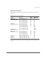
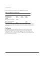
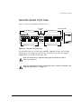
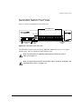
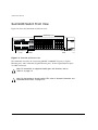
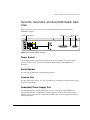
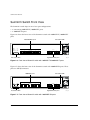
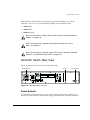
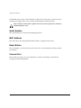
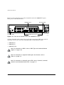
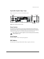
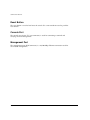
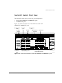
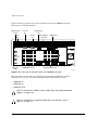
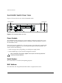
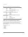
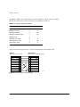
Summit Switch Hardware
Installation Guide
Extreme Networks, Inc.
3585 Monroe Street
Santa Clara, California 95051
(888) 257-3000
http://www.extremenetworks.com
Published: December 2000
Part number: 100037-00 Rev. C
©2000 Extreme Networks, Inc. All rights reserved. Extreme Networks and BlackDiamond are
registered trademarks of Extreme Networks, Inc. in the United States and certain other jurisdictions.
ExtremeWare, ExtremeWare Vista, ExtremeWorks, ExtremeAssist, ExtremeAssist1, ExtremeAssist2,
PartnerAssist, Extreme Standby Router Protocol, ESRP, SmartTraps, Alpine, Summit, Summit1i,
Summit4, Summit4/FX, Summit5i, Summit7i, Summit24, Summit48, Summit48i, Summit Virtual
Chassis, SummitLink, SummitGbX, SummitRPS and the Extreme Networks logo are trademarks of
Extreme Networks, Inc., which may be registered or pending registration in certain jurisdictions. The
Extreme Turbodrive logo is a service mark of Extreme Networks, which may be registered or pending
registration in certain jurisdictions. All other registered trademarks, trademarks and service marks are
property of their respective owners. Specifications are subject to change without notice.
ii
Contents
Preface
Introduction
xi
Conventions
xii
Related Publications
1
xiii
Summit Switch Overview
Summit Switch Models
1-1
Summary of Features
1-2
Memory Requirements
Port Connections
Full-Duplex
1-3
1-3
1-6
Summit4 Switch Front View
1-7
Summit4/FX Switch Front View
1-8
Summit24 Switch Front View
1-9
Summit48 Switch Front View
1-10
Summit4, Summit24, and Summit48 Switch Rear View
Power Socket
Serial Number
Console Port
Redundant Power Supply Port
MAC Address
1-11
1-11
1-11
1-11
1-11
1-12
Summit Switch Hardware Installation Guide
iii
Reset Button
iv
1-12
Summit4, Summit24, and Summit48 Switch LEDs
1-12
Summit1i Switch Front View
1-14
Summit1i Switch Rear View
Power Sockets
Serial Number
MAC Address
Reset Button
Console Port
1-15
1-15
1-16
1-16
1-16
1-16
Summit5i Switch Front View
1-17
Summit5i Switch Rear View
Power Sockets
Serial Number
MAC Address
Reset Button
Console Port
Management Port
1-19
1-19
1-19
1-19
1-20
1-20
1-20
Summit7i Switch Front View
Reset Button
Console Port
Modem Port
Management Port
PCMCIA Slot
1-21
1-23
1-23
1-23
1-23
1-23
Summit7i Switch Rear View
Power Sockets
Serial Number
MAC Address
1-24
1-24
1-24
1-24
Summit48i Switch Front View
1-25
Summit48i Switch Rear View
Power Sockets
Serial Number
MAC Address
Reset Button
Console Port
1-26
1-26
1-26
1-26
1-27
1-27
Summit Switch Hardware Installation Guide
2
A
Summit1i, Summit5i, Summit7i, and Summit48i Switch LEDs
1-27
GBIC Type and Hardware/Software Support
1-28
Installation and Setup
Following Safety Information
2-1
Determining the Switch Location
2-1
Installing the Summit Switch
Rack Mounting
Free-Standing
Stacking the Switch and Other Devices
2-2
2-2
2-5
2-5
Connecting Equipment to the Console Port
2-5
Powering On the Switch
2-7
Checking the Installation
2-7
Logging In for the First Time
2-8
Installing the Gigabit Interface Connector (GBIC)
2-9
Safety Information
Important Safety Information
Power
Power Cord
Fuse
Connections
Lithium Battery
B
A-1
A-1
A-2
A-2
A-3
A-3
Technical Specifications
Summit4, Summit4/FX, Summit24, and Summit48 Switch
Specifications
B-1
Summit1i, Summit5i, Summit7i, and Summit48i Switch
Specifications
B-2
Index
Summit Switch Hardware Installation Guide
v
vi
Summit Switch Hardware Installation Guide
Figures
1-1
1-2
1-3
1-4
1-5
1-6
1-7
1-8
1-9
1-10
1-11
1-12
1-13
1-14
1-15
1-16
1-17
2-1
2-2
2-3
2-4
2-5
Summit Switch Hardware Installation Guide
Summit4 switch front view
Summit4/FX switch front view
Summit24 switch front view
Summit48 switch front view
Summit switch rear view
Front view of Summit1i switch with 100BASE-TX/
1000BASE-T ports
Front view of Summit1i switch with 1000BASE-SX ports
Summit1i switch rear view
Front view of Summit5i switch with 100BASE-TX/
1000BASE-T ports
Front view of Summit5i switch with 1000BASE-SX ports
Front view of Summit5i switch with 1000BASE-LX ports
Summit5i switch rear view
Front view of Summit7i switch with 100BASE-TX/
1000BASE-T ports
Front view of Summit7i switch with 1000BASE-SX ports
Summit7i switch rear view
Front view of Summit48i switch
Summit48i switch rear view
Rack-mount helper bracket
Fitting the mounting bracket
Null-modem cable pin-outs
PC-AT serial null-modem cable pin-outs
GBIC modules
1-7
1-8
1-9
1-10
1-11
1-14
1-14
1-15
1-17
1-17
1-18
1-19
1-21
1-22
1-24
1-25
1-26
2-3
2-4
2-6
2-7
2-9
vii
viii
Summit Switch Hardware Installation Guide
Tables
1
2
1-1
1-2
1-3
1-4
1-5
2-1
Summit Switch Hardware Installation Guide
Notice Icons
Text Conventions
Summit Switch Port Configurations
Media Types and Distances
1000BASE-LX70 Specifications
Summit4, Summit24, and Summit48 Switch LED Behavior
Summit1i, Summit5i, Summit7i, and Summit48i Switch
LED Behavior
Console Connector Pinouts
xii
xii
1-4
1-5
1-6
1-12
1-27
2-6
ix
x
Summit Switch Hardware Installation Guide
Preface
This Preface provides an overview of this guide, describes guide conventions, and lists
other publications that might be useful.
Introduction
This guide provides the required information to install the Summit™ switch.
This guide is intended for use by network administrators who are responsible for
installing and setting up network equipment. It assumes a basic working knowledge of
the following:
• Local Area Networks (LANs)
• Ethernet concepts
• Ethernet switching and bridging concepts
• Routing concepts
• Simple Network Management Protocol (SNMP)
For information on configuring the Summit switch, refer to the ExtremeWare Software
User Guide.
Note: If the information in the Release Notes shipped with your switch differs
from the information in this guide, follow the Release Notes.
Summit Switch Hardware Installation Guide
xi
Preface
Conventions
Table 1 and Table 2 list conventions used throughout this guide.
Table 1: Notice Icons
Icon
Notice Type
Alerts you to...
Note
Important features or instructions.
Caution
Risk of personal injury, system damage,
or loss of data.
Warning
Risk of severe personal injury.
Table 2: Text Conventions
Convention
Description
Screen displays
This typeface represents information as it appears on the screen,
or command syntax.
Screen displays bold
This typeface represents commands that you type.
The words “enter”
and “type”
When you see the word “enter” in this guide, you must type
something, and then press the Return or Enter key. Do not press
the Return or Enter key when an instruction simply says “type.”
[Key] names
Key names appear in text in one of two ways:
■
Referred to by their labels, such as “the Return key” or “the
Escape key”
■
Written with brackets, such as [Return] or [Esc]
If you must press two or more keys simultaneously, the key names
are linked with a plus sign (+). Example:
Press [Ctrl]+[Alt]+[Del].
Words in italicized type
xii
Italics emphasize a point or denote new terms at the place where
they are defined in the text.
Summit Switch Hardware Installation Guide
Related Publications
Related Publications
The Summit switch documentation set includes the following:
• ExtremeWare Software User Guide
• ExtremeWare Quick Reference Guide
• ExtremeWare Release Notes
Documentation for Extreme Networks products is available on the World Wide Web at
the following location:
• Extreme Networks home page http://www.extremenetworks.com/
Summit Switch Hardware Installation Guide
xiii
Preface
xiv
Summit Switch Hardware Installation Guide
1
Summit Switch Overview
This chapter describes the following:
• Summit switch models
• Summit switch features
• Summit switch memory requirements
• Summit switch front views
• Summit switch rear views
• Summit switch LEDs
• Factory default settings
Summit Switch Models
The following models comprise the Summit family of switches:
• Summit4 switch
• Summit4/FX switch
• Summit24 switch
• Summit48 switch
• Summit1i switch
• Summit5i switch
• Summit7i switch
Summit Switch Hardware Installation Guide
1-1
Summit Switch Overview
• Summit48i switch
Summary of Features
Summit switches support the following ExtremeWare features:
• Virtual local area networks (VLANs) including support for IEEE 802.1Q and IEEE
802.1p
• VLAN aggregation
• Spanning Tree Protocol (STP) (IEEE 802.1D) with multiple STP domains
• Policy-Based Quality of Service (PB-QoS)
• Wire-speed Internet Protocol (IP) routing
• IP Multinetting
• DHCP/BOOTP Relay
• Extreme Standby Router Protocol (ESRP)
• Routing Information Protocol (RIP) version 1 and RIP version 2
• Open Shortest Path First (OSPF) routing protocol
• Border Gateway Protocol (BGP) version 4
• IPX routing, including RIP and Service Advertisement Protocol (SAP)
• Wire-speed IP multicast routing support
• Diffserv support
• Access-policy support for routing protocols
• Access list support for packet filtering
• IGMP snooping to control IP multicast traffic
• Distance Vector Multicast Routing Protocol (DVMRP)
• Protocol Independent Multicast-Dense Mode (PIM-DM)
• Protocol Independent Multicast-Sparse Mode (PIM-SM)
• Wire-speed IPX, IPX/RIP, and IPX/SAP support
• Server Load Balancing (SLB) support
• RADIUS client and per-command authentication support
• TACACS+ support
1-2
Summit Switch Hardware Installation Guide
Memory Requirements
• Console command-line interface (CLI) connection
• Telnet CLI connection
• SSH2 connection
• ExtremeWare Vista Web-based management interface
• Simple Network Management Protocol (SNMP) support
• Remote Monitoring (RMON)
Memory Requirements
Your “i” series Summit switch must have 32 MB of DRAM in order to support the
features in ExtremeWare version 4.0 and above. This is not an issue for Summit24 and
Summit48 switch models, and all currently shipping switches contain 32 MB. Some
earlier models of the Summit switch shipped with 16 MB, and must be upgraded to
support ExtremeWare version 4.0 and above.
To determine the memory size in your switch, use the following command:
show memory
For Summit switches running ExtremeWare 4.0 and above, the switch indicates the total
DRAM size in megabytes as part of the output. For Summit switches running previous
ExtremeWare releases, you must calculate the memory by taking the sum of the bytes
listed under current free and adding to it the bytes listed under current alloc. If
the sum is greater than 16,000,000, there is no need to upgrade the memory on the
switch. If this is not the case, please contact your supplier.
Port Connections
The major difference between the models of the Summit switch is the port
configurations on each switch model. Summit switches use a combination of the
following types of ports:
• 1000BASE-SX ports using 850 nm duplex SC connectors
• 1000BASE-LX ports using 1300 nm duplex SC connectors
• 1000BASE-SX ports using MT-RJ connectors
• 1000BASE-LX ports using MT-RJ connectors
Summit Switch Hardware Installation Guide
1-3
Summit Switch Overview
• Modular 1000BASE-SX and 1000BASE-LX using Gigabit Interface Connectors
(GBICs)
• 10BASE-T/100BASE-TX ports using RJ-45 connectors
• 100BASE-FX ports using 1300 nm duplex SC connectors
• 100BASE-TX/1000BASE-T ports using RJ-45 connectors
Table 1-1 describes port configurations available on the different Summit switch models.
Table 1-1: Summit Switch Port Configurations
Ethernet Ports
Switch Model
1000BASE 1000BASE
-SX
-LX
Summit4
6
Summit4/FX
6
100/1000
BASE-T
Redun- 10BASE-T/
dant
100BASE- 100BASE
-FX
GBIC GBIC
TX
16
16
Summit24
1
1
24
Summit48
2
2
48
2
48
Summit1i (SX)
6
2
Summit1i (TX)
Summit5i (SX)
6
12
Summit5i (LX)
Summit7i (SX)
Summit7i (TX)
Summit48i (TX)
1-4
4
12
Summit5i (TX)
2
4
12
28
4
4
28
4
2
Summit Switch Hardware Installation Guide
Memory Requirements
Media Types and Distances
Table 1-2 describes the media types and distances for the different types of Summit
switch ports.
Table 1-2: Media Types and Distances
Standard
Media Type
MHz•km
Rating
Maximum Distance (Meters)
1000BASE-SX
(850 nm optical window)
50/125 µm Multimode Fiber
400
500
50/125 µm Multimode Fiber
500
550
62.5/125 µm Multimode Fiber
160
220
62.5/125 µm Multimode Fiber
200
275
50/125 µm Multimode Fiber
400
550
50/125 µm Multimode Fiber
500
550
62.5/125 µm Multimode Fiber
500
550
10/125 µm Single-mode Fiber
–
5,000
10/125 µm Single-mode Fiber*
–
10,000
1000BASE-LX70
(1550 nm optical window)
10/125 µm Single-mode Fiber
–
70,000
100BASE-FX
(1300 nm optical window)
50/125 µm Multimode Fiber
400
2000
50/125 µm Multimode Fiber
500
2000
62.5/125 µm Multimode Fiber
400
2000
62.5/125 µm Multimode Fiber
500
2000
1000BASE-LX
(1300 nm optical window)
1000BASE-T
Category 5 and higher UTP Cable
–
100
100BASE-TX
Category 5 and higher UTP Cable
–
100
10BASE-T
Category 3 and higher UTP Cable
–
100
*Extreme Networks proprietary. Connections between two Extreme Networks 1000BASE-LX interfaces can use a maximum
distance of 10,000 meters. However, it interoperates with standard 1000BASE-LX ports and supports a maximum distance of
5,000 meters.
Summit Switch Hardware Installation Guide
1-5
Summit Switch Overview
Table 1-3 describes the specifications for the 1000BASE-LX70 interface.
Table 1-3: 1000BASE-LX70 Specifications
Parameter
Minimum
Typical
Maximum
Optical Output Power
0 dBm
3 dBm
5 dBm*
Center Wavelength
1540 nm
1550 nm
1560 nm
Transceiver
Receiver
Optical Input Power Sensitivity
-20 dBm
Optical Input Power Maximum
Operating Wavelength
-3 dBm
1200 nm
1560 nm
*The transmitter output power level for the 1000BASE-LX70 is +5 dBm. The maximum allowable receiver input power level is
-3 dBm. Therefore, there is a minimum of 8 dB loss required for the link to operate without errors. This minimum required loss
can be achieved using a fiber length of 32 km (0.25 dB/km provides 8 dB loss), or by adding 10 dB of fixed optical attenuator
at the receiver end.
Full-Duplex
The Summit switch provides full-duplex support for all ports. Full-duplex allows
frames to be transmitted and received simultaneously and, in effect, doubles the
bandwidth available on a link. All 10/100/1000 Mbps ports on the Summit switch
autonegotiate for half- or full-duplex operation. Gigabit Ethernet and 100BASE-FX ports
operate in full-duplex mode, only.
1-6
Summit Switch Hardware Installation Guide
Summit4 Switch Front View
Summit4 Switch Front View
Figure 1-1 shows the Summit4 switch front view.
1
2
3
4
5
6
Unit status LEDs
Port status
LEDs
10/100 Mbps ports
7
8
AMBER
= ACTIVITY
GREEN
= LINK OK
FLASHING GREEN = DISABLED
1
2
9
10 11 12 13 14
3
4
5
6
7
10/100 Mbps ports
9
10
11
12
13
14
15
16
8
15 16
ACTIVITY
17 18 19 20 21 22
17 18 19 20 21 22
17
18
19
LINK
Gigabit Ethernet ports
20
21
22
Gigabit Ethernet ports
Sum4fr
Figure 1-1: Summit4 switch front view
The Summit4 switch has 16 autosensing 10BASE-T/100BASE-TX ports and 6 Gigabit
Ethernet ports. The Gigabit Ethernet ports use standard SC connectors and support
1000BASE-SX over multimode fiber-optic cable.
Note: For information on supported media types and distances, refer to
Table 1-2 on page 1-5.
Note: For information on Summit switch LEDs, refer to “Summit4, Summit24, and
Summit48 Switch LEDs,” on page 1-12.
Summit Switch Hardware Installation Guide
1-7
Summit Switch Overview
Summit4/FX Switch Front View
Figure 1-2 shows the Summit4/FX switch front view.
1
2
Unit status LEDs
Port status
LEDs
100 Mbps ports
3
4
100 Mbps ports
5
6
7
8
13
14
15
16
FLASHING AMBER = TRAFFIC
SOLID AMBER
= DISABLED
GREEN
= ENABLED, LINK OK
9
10
1
11
2
1
2
9
10 11 12 13 14
3
12
3
4
5
6
7
8
15 16
LINK
1
2
3
4
5
6
1
2
3
4
5
6
ACTIVITY
Gigabit Ethernet ports
4
5
6
Gigabit Ethernet ports
Sum4fx
Figure 1-2: Summit4/FX switch front view
The Summit4/FX switch has 16 100BASE-FX ports and 6 Gigabit Ethernet ports. All
ports use standard SC connectors. The Gigabit Ethernet ports support 1000BASE-SX
over multimode fiber-optic cable.
Note: For information on supported media types and distances, refer to
Table 1-2 on page 1-5.
Note: For information on Summit switch LEDs, refer to “Summit4, Summit24, and
Summit48 Switch LEDs,” on page 1-12.
1-8
Summit Switch Hardware Installation Guide
Summit24 Switch Front View
Summit24 Switch Front View
Figure 1-3 shows the Summit24 switch front view.
10/100 Mbps ports
AMBER
= ACTIVITY
GREEN
= LINK OK
FLASHING GREEN = DISABLED
1
1
2
3
4
7
8
9
10 11 12
5
2
3
4
5
6
7
8
9
10
11
12
10/100BASE-TX
MDI-X
POWER
6
A 25 25R 13 14 15 16 17 18
1000BASE-X
L 25 25R 19 20 21 22 23 24
25
25R
Gigabit Ethernet
ports
13
14
15
Port status
LEDs
16
17
18
19
20
21
22
23
24
MGMT.
Unit status
LEDs
Sum24_co
Figure 1-3: Summit24 switch front view
The Summit24 switch has 24 autosensing 10BASE-T/100BASE-TX ports, one Gigabit
Ethernet port, and one redundant Gigabit Ethernet port.
Note: For information on supported media types and distances, refer to
Table 1-2 on page 1-5.
Note: For information on Summit switch LEDs, refer to “Summit4, Summit24, and
Summit48 Switch LEDs,” on page 1-12.
Summit Switch Hardware Installation Guide
1-9
Summit Switch Overview
Summit48 Switch Front View
Figure 1-4 shows the Summit48 switch front view.
10/100 Mbps ports
1
2
3
4
7
8
9
10 11 12
5
1
2
3
4
5
6
7
8
9
10
11
12
13
25
14
26
15
27
16
28
17
29
18
30
19
31
20
32
21
33
22
34
23
35
24
36
6
A 49 49R 13 14 15 16 17 18
L 49 49R 19 20 21 22 23 24
49
49R
1000 BASE-X
AMBER
= ACTIVITY
GREEN
= LINK OK
FLASHING GREEN = DISABLED
10/100 BASE-X
MDI-X
25 26 27 28 29 30
Power
31 32 33 34 35 36
A 50 50R 37 38 39 40 41 42
Mgmt.
L 50 50R 43 44 45 46 47 48
50
50R
Gigabit Ethernet
ports
37
38
39
Port status
LEDs
40
41
42
43
44
45
46
47
48
Unit status
LEDs
Sum48fr
Figure 1-4: Summit48 switch front view
The Summit48 switch has 48 autosensing 10BASE-T/100BASE-TX ports, 2 Gigabit
Ethernet ports, and 2 redundant Gigabit Ethernet ports. All the Gigabit Ethernet ports
use GBIC connectors.
Note: For information on supported media types and distances, refer to
Table 1-2 on page 1-5.
Note: For information on Summit switch LEDs, refer to “Summit4, Summit24, and
Summit48 Switch LEDs,” on page 1-12.
1-10
Summit Switch Hardware Installation Guide
Summit4, Summit24, and Summit48 Switch Rear View
Summit4, Summit24, and Summit48 Switch Rear
View
Figure 1-5 shows the rear view for the Summit4, Summit4/FX, Summit24, and
Summit48 switches.
Power socket and fuse
RPS port
Console port
Reset button
rear_Sum
Figure 1-5: Summit switch rear view
Power Socket
The Summit switch automatically adjusts to the supply voltage. The power supply
operates down to 90 V. The fuse is suitable for both 110 VAC and 220-240 VAC
operation.
Serial Number
Use this serial number for fault-reporting purposes.
Console Port
Use the console port (9-pin, “D” type connector) for connecting a terminal and carrying
out local management.
Redundant Power Supply Port
The redundant power supply (RPS) port is used to connect to a Summit RPS. The
Summit RPS provides a redundant, load-shared power source to the Summit. If the
primary power source for the switch fails, the RPS takes over, ensuring uninterrupted
network operation.
Summit Switch Hardware Installation Guide
1-11
Summit Switch Overview
When connected to a Summit RPS, the Summit switch can provide status on power and
fan operation of the RPS through SNMP, the command-line interface, and the Web
interface.
The Summit RPS can simultaneously provide power for as many as two Summit
switches.
MAC Address
This label shows the unique Ethernet MAC address assigned to this device.
Reset Button
The reset button is used to hard reset the switch. Use a non-conductive tool to push the
reset button.
Summit4, Summit24, and Summit48 Switch
LEDs
Table 1-4 describes the light emitting diode (LED) behavior on the Summit4,
Summit4/FX, Summit24, and Summit48 switches.
.
Table 1-4: Summit4, Summit24, and Summit48 Switch LED Behavior
Unit Status LEDs
LED
Color
Indicates
Power
Green
The Summit switch is powered up.
Yellow
The Summit switch is indicating a power, overheat, or fan failure.
MGMT
Green flashing
■
Slow
The Summit switch is operating normally.
■
Fast
Power On Self Test (POST) or software download in progress.
Yellow
1-12
The Summit has failed its POST.
Summit Switch Hardware Installation Guide
Summit4, Summit24, and Summit48 Switch LEDs
Table 1-4: Summit4, Summit24, and Summit48 Switch LED Behavior (continued)
10/100 Mbps Port Status LEDs
Color
Indicates
Green
Link is present; port is enabled.
Yellow
Frames are being transmitted/received on this port.
Green flashing
Link is present; port is disabled.
Off
Link is not present.
Gigabit Ethernet Port Status LEDs
LED
Color
Indicates
Packet
Yellow
Frames are being transmitted/received on this port.
Off
No activity on this port.
Green on
Link is present; port is enabled; full-duplex operation.
Green flashing
Link is present; port is disabled.
Off
Link is not present.
Status
Summit Switch Hardware Installation Guide
1-13
Summit Switch Overview
Summit1i Switch Front View
The Summit1i switch ships in one of two port configurations:
• 6 autosensing 100BASE-TX/1000BASE-T ports
• 6 1000BASE-SX ports
Figure 1-6 shows the front view of the Summit1i switch with 100BASE-TX/1000BASE-T
ports.
100/1000 Mbps ports
TOP ROW:
GREEN
= 1000Mbps
BOTTOM ROW:
AMBER
GREEN
FLASHING GREEN
= ACTIVITY
= LINK OK
= DISABLED
1
2
3
100BASE-TX/
1000BASE-T
4
5
Unit status LEDs
6
7
1000BASE-X
8
PSU A
PSU B
1
2
3
4
5
6
7
8
MGMT
Port status LEDs
Gigabit Ethernet ports
SHG_S1T
Figure 1-6: Front view of Summit1i switch with 100BASE-TX/1000BASE-T ports
Figure 1-7 shows the front view of the Summit1i switch with 1000BASE-SX ports. These
ports use MT-RJ connectors.
1000 Mbps ports
1
1
2
3
4
5
6
7
2
3
4
Unit status LEDs
5
6
7
8
8
Port status LEDs
Gigabit Ethernet ports
SHG_S1SX
Figure 1-7: Front view of Summit1i switch with 1000BASE-SX ports
1-14
Summit Switch Hardware Installation Guide
Summit1i Switch Rear View
Both Summit1i switch models also provide two unpopulated GBIC ports with SC
connectors. You can use any of the following GBICs in the Summit1i switch:
• 1000BASE-SX
• 1000BASE-LX
• 1000BASE-LX70
Note: For information on GBICs, refer to “GBIC Type and Hardware/Software
Support,” on page 1-28.
Note: For information on supported media types and distances, refer to
Table 1-2 on page 1-5.
Note: For information on Summit1i switch LEDs, refer to “Summit1i, Summit5i,
Summit7i, and Summit48i Switch LEDs,” on page 1-27.
Summit1i Switch Rear View
Figure 1-8 shows the rear view for the Summit1i switch.
AC Connectors
Reset
Console port
SHG_Rr1
Figure 1-8: Summit1i switch rear view
Power Sockets
The Summit1i switch supports up to two power supplies. Each power supply has its
own power socket. When a second power supply is installed, both provide a redundant,
Summit Switch Hardware Installation Guide
1-15
Summit Switch Overview
load-shared power source to the Summit1i switch. If one of the power sources fails, the
second power supply takes over, ensuring uninterrupted network operation.
Note: Summit1i switch power supplies must be serviced by personnel trained by
Extreme Networks, only.
Serial Number
The serial number is used for fault-reporting purposes.
MAC Address
This label shows the unique Ethernet MAC address assigned to this device.
Reset Button
The reset button is used to hard reset the switch. Use a non-conductive tool to push the
reset button.
Console Port
The console port (9-pin, “D” type connector) is used for connecting a terminal and
carrying out local management.
1-16
Summit Switch Hardware Installation Guide
Summit5i Switch Front View
Summit5i Switch Front View
The Summit5i switch ships in one of three port configurations:
• 12 autosensing 100BASE-TX/1000BASE-T ports
• 12 1000BASE-SX ports
• 12 1000BASE-LX ports
Figure 1-9 shows the front view of the Summit5i switch with 100BASE-TX/1000BASE-T
ports.
100/1000 Mbps ports
TOP ROWS:
GREEN
1
2
3
1
2
3
4
9
10
11
12
100BASE-TX/
1000BASE-T
5
Unit status LEDs
6
7
8
= 1000Mbps
4
5
BOTTOM ROWS:
AMBER
GREEN
FLASHING GREEN
6
7
8
= ACTIVITY
= LINK OK
= DISABLED
13
1000BASE-X
14
15
16
PSU A
PSU B
9
10
11
12
13
14
15
16
MGMT
Port status LEDs
Gigabit Ethernet ports
SHG_S5T
Figure 1-9: Front view of Summit5i switch with 100BASE-TX/1000BASE-T ports
Figure 1-10 shows the front view of the Summit5i switch with 1000BASE-SX ports.
These ports use MT-RJ connectors.
1000 Mbps ports
1
2
3
4
9
10
11
12
Port status LEDs
5
13
Unit status LEDs
6
14
7
8
15
16
Gigabit Ethernet ports
SHG_S5SX
Figure 1-10: Front view of Summit5i switch with 1000BASE-SX ports
Summit Switch Hardware Installation Guide
1-17
Summit Switch Overview
Figure 1-11 shows the front view of the Summit5i switch with 1000BASE-LX ports.
These ports use MT-RJ connectors.
1000 Mbps ports
1
2
3
4
9
10
11
12
Port status LEDs
5
13
Unit status LEDs
6
14
7
8
15
16
Gigabit Ethernet ports
SHG_S5LX
Figure 1-11: Front view of Summit5i switch with 1000BASE-LX ports
All three Summit5i switch models also provide four unpopulated GBIC ports with SC
connectors. You can use any of the following GBICs in the Summit5i switch:
• 1000BASE-SX
• 1000BASE-LX
• 1000BASE-LX70
Note: For information on GBICs, refer to “GBIC Type and Hardware/Software
Support,” on page 1-28.
Note: For information on supported media types and distances, refer to
Table 1-2 on page 1-5.
Note: For information on Summit5i switch LEDs, refer to “Summit1i, Summit5i,
Summit7i, and Summit48i Switch LEDs,” on page 1-27.
1-18
Summit Switch Hardware Installation Guide
Summit5i Switch Rear View
Summit5i Switch Rear View
Figure 1-12 shows the rear view for the Summit5i switch.
AC Connectors
Reset
Console port
Ethernet port
SHG_Rr5
Figure 1-12: Summit5i switch rear view
Power Sockets
The Summit5i switch supports up to two power supplies. Each power supply has its
own power socket. When a second power supply is installed, both provide a redundant,
load-shared power source to the Summit5i switch. If one of the power sources fails, the
second power supply takes over, ensuring uninterrupted network operation.
Note: Summit5i switch power supplies must be serviced by personnel trained by
Extreme Networks, only.
Serial Number
The serial number is used for fault-reporting purposes.
MAC Address
This label shows the unique Ethernet MAC address assigned to this device.
Summit Switch Hardware Installation Guide
1-19
Summit Switch Overview
Reset Button
The reset button is used to hard reset the switch. Use a non-conductive tool to push the
reset button.
Console Port
The console port (9-pin, “D” type connector) is used for connecting a terminal and
carrying out local management.
Management Port
The management port (RJ-45 connector) is a 10/100 Mbps Ethernet connection used for
out-of-band management.
1-20
Summit Switch Hardware Installation Guide
Summit7i Switch Front View
Summit7i Switch Front View
The Summit7i switch ships in one of two port configurations:
• 28 autosensing 100BASE-TX/1000BASE-T ports
• 28 1000BASE-SX ports
Figure 1-13 shows the front view of the Summit7i switch with
100BASE-TX/1000BASE-T ports.
Module status
LEDs
Console
port
Reset
button
Management
port
Modem
port
Management
port LED
PCMCIA slot
PSU A
PSU B
MGMT
LINK/ACTIVITY
CONSOLE
1
2
3
4
5
TOP ROWS:
GREEN
6
7
PCMCIA
10BASE-T/100BASE-TX
MGMT PORT
MODEM
1
2
3
4
5
6
7
8
9
10
11
12
13
14
15
16
17
18
19
20
21
22
23
24
25
26
27
28
8
= 1000 Mbps
9 10 11 12 13 14 15 16
BOTTOM ROWS:
AMBER
GREEN
FLASHING GREEN
= ACTIVITY
= LINK OK
= DISABLED
17 18 19 20 21 22 23 24
29
30
31
32
25 26 27 28 29 30 31 32
Port status
LEDs
100/1000 Mbps ports
Gigabit Ethernet ports
EW_S7iTX
Figure 1-13: Front view of Summit7i switch with 100BASE-TX/1000BASE-T ports
Summit Switch Hardware Installation Guide
1-21
Summit Switch Overview
Figure 1-14 shows the front view of the Summit7i switch with 1000BASE-SX ports.
These ports use MT-RJ connectors.
Module status
LEDs
Console
port
Reset
button
Management
port
Modem
port
Management
port LED
PCMCIA slot
PSU A
PSU B
MGMT
LINK/ACTIVITY
CONSOLE
1
2
3
4
5
6
7
8
MODEM
PCMCIA
10BASE-T/100BASE-TX
MGMT PORT
1
2
3
4
5
6
7
8
9
10
11
12
13
14
15
16
17
18
19
20
21
22
23
24
25
26
27
28
9 10 11 12
13 14 15 16
AMBER
GREEN
FLASHING GREEN
= ACTIVITY
= LINK OK
= DISABLED
17 18 19 20
21 22 23 24
29
30
31
32
25 26 27 28
29 30 31 32
Port status
LEDs
1000BASE-SX ports
Gigabit Ethernet ports
EW_S7iSX
Figure 1-14: Front view of Summit7i switch with 1000BASE-SX ports
Both Summit7i switch models also provide four unpopulated GBIC ports with SC
connectors. You can use any of the following GBICs in the Summit7i switch:
• 1000BASE-SX
• 1000BASE-LX
• 1000BASE-LX70
Note: For information on GBICs, refer to “GBIC Type and Hardware/Software
Support,” on page 1-28.
Note: For information on supported media types and distances, refer to
Table 1-2 on page 1-5.
1-22
Summit Switch Hardware Installation Guide
Summit7i Switch Front View
Note: For information on Summit7i switch LEDs, refer to “Summit1i, Summit5i,
Summit7i, and Summit48i Switch LEDs,” on page 1-27.
Reset Button
The reset button is used to hard reset the switch. Use a non-conductive tool to push the
reset button.
Console Port
The console port (9-pin, “D” type connector) is used for connecting a terminal and
carrying out local management.
Modem Port
The modem port is used to connect a modem for remote access to the command line
interface (CLI).
Management Port
The management port (RJ-45 connector) is a 10/100 Mbps Ethernet connection used for
out-of-band management.
PCMCIA Slot
The PCMCIA slot is reserved for future use.
Summit Switch Hardware Installation Guide
1-23
Summit Switch Overview
Summit7i Switch Rear View
Figure 1-15 shows the rear view for the Summit7i switch.
Power socket
Power socket
EW_S7iRr
Figure 1-15: Summit7i switch rear view
Power Sockets
The Summit7i switch supports up to two power supplies. Each power supply has its
own power socket. When a second power supply is installed, both provide a redundant,
load-shared power source to the Summit7i switch. If one of the power sources fails, the
second power supply takes over, ensuring uninterrupted network operation.
Note: Summit7i switch power supplies must only be serviced by personnel
trained by Extreme Networks.
Serial Number
The serial number is used for fault-reporting purposes.
MAC Address
This label shows the unique Ethernet MAC address assigned to this device.
1-24
Summit Switch Hardware Installation Guide
Summit48i Switch Front View
Summit48i Switch Front View
The Summit48i switch ships with 48 autosensing 10BASE-T/100BASE-TX ports.
Figure 1-16 shows the front view of the Summit48i switch.
Gigabit Ethernet ports
49
49R
50
Unit status LEDs
1
2
3
4
5
6
7
8
50R
49 49R
50 50R
Port status LEDs
17
18
19
20
21
22
23
24
9
25
10
26
11
27
12
28
13
29
14
30
15
31
16
32
33
34
35
36
37
38
39
40
41
42
43
44
45
46
47
48
10/100 Mbps ports
S48i_fr
Figure 1-16: Front view of Summit48i switch
The Summit48i switch has 2 Gigabit Ethernet ports and 2 redundant Gigabit Ethernet
ports. All the Gigabit Ethernet ports use GBIC connectors. You can use any of the
following GBICs in the Summit48i switch:
• 1000BASE-SX
• 1000BASE-LX
• 1000BASE-LX70
Note: For information on GBICs, refer to “GBIC Type and Hardware/Software
Support,” on page 1-28.
Note: For information on supported media types and distances, refer to
Table 1-2 on page 1-5.
Note: For information on Summit48i switch LEDs, refer to “Summit1i, Summit5i,
Summit7i, and Summit48i Switch LEDs,” on page 1-27.
Summit Switch Hardware Installation Guide
1-25
Summit Switch Overview
Summit48i Switch Rear View
Figure 1-17 shows the rear view for the Summit48i switch.
AC Connectors
Console port
Reset
S48i_rr
Figure 1-17: Summit48i switch rear view
Power Sockets
The Summit48i switch supports two power supplies. Each power supply has its own
power socket. The power supplies provide a redundant, load-shared power source to
the Summit48i switch.
If one of the power supplies fails, or if source power to one of the power supplies fails,
the second power supply takes over, ensuring uninterrupted network operation. The
switch also does the following:
• Send a message to the syslog telling you which power supply failed
• Send an SNMP trap to your network management software
Note: Summit48i switch power supplies must only be serviced by personnel
trained by Extreme Networks.
Serial Number
The serial number is used for fault-reporting purposes.
MAC Address
This label shows the unique Ethernet MAC address assigned to this device.
1-26
Summit Switch Hardware Installation Guide
Summit1i, Summit5i, Summit7i, and Summit48i Switch LEDs
Reset Button
The reset button is used to hard reset the switch. Use a non-conductive tool to push the
reset button.
Console Port
The console port (9-pin, “D” type connector) is used for connecting a terminal and
carrying out local management.
Summit1i, Summit5i, Summit7i, and Summit48i
Switch LEDs
Table 1-5 describes the light emitting diode (LED) behavior on the Summit1i, Summit5i,
Summit7i, and Summit48i switches.
Table 1-5: Summit1i, Summit5i, Summit7i, and Summit48i Switch LED Behavior
Unit Status LEDs
LED
Color
Indicates
Power
(A and B)
Green
The indicated power supply unit (PSU) is powered up.
Yellow
The indicated PSU has a failure.
Green/Yellow
Flashing
The AC power cord is not inserted correctly.
Off
The PSU is not receiving power or no PSU is present.
MGMT
Green flashing
■
Slow
The switch is operating normally.
■
Fast
Power On Self Test (POST) or software download in progress.
Yellow
Summit Switch Hardware Installation Guide
The switch has failed its POST or is experiencing an overheat
or fan failure.
1-27
Summit Switch Overview
Table 1-5: Summit1i, Summit5i, Summit7i, and Summit48i Switch LED Behavior
Port Status LEDs (bottom row for 100BASE-TX/1000BASE-T ports)
Color
Indicates
Green
Link is present; port is enabled.
Yellow
Frames are being transmitted/received on this port.
Green flashing
Link is present; port is disabled.
Off
Link is not present.
100/1000 Mbps Speed LEDs (top row for 100BASE-TX/1000BASE-T ports)
Color
Indicates
Green
1000 Mbps
Off
100 Mbps
10/100 Management Port LED (right of 10BASE-T/100BASE-TX Management Port on
Summit5i and Summit7i)
Color
Indicates
Green
Link is present.
Yellow
Frames are being transmitted.
Off
Link is not present.
GBIC Type and Hardware/Software Support
The switch supports two types of GBICs: the Parallel ID GBIC and the Serial ID GBIC.
The system uses identifier bits to determine the media type for the GBIC that is
installed. Initial ExtremeWare versions do not support Serial ID GBICs. If Serial ID
GBICs are installed in a switch with an initial software release, the switch will not bring
up the link on GBIC ports.
GBICs are used in these switches:
• Summit24
• Summit48
• Summit1i
• Summit5i
• Summit7i
• Summit48i
1-28
Summit Switch Hardware Installation Guide
2
Installation and Setup
This chapter describes the following:
• How to decide where to install the Summit switch
• Gigabit Ethernet configuration rules
• How to install the switch in a rack or free-standing
• How to connect equipment to the console port
• How to check the installation using the Power On Self-Test (POST)
Caution: Use of controls or adjustments of performance or procedures other than
those specified herein can result in hazardous radiation exposure.
Following Safety Information
Before installing or removing any components of the switch, or before carrying out any
maintenance procedures, read the safety information provided in Appendix A of this
guide.
Determining the Switch Location
The Summit switch is suited for use in the office, where it can be free-standing or
mounted in a standard 19-inch equipment rack. Alternately, the device can be
Summit Switch Hardware Installation Guide
2-1
Installation and Setup
rack-mounted in a wiring closet or equipment room. Two mounting brackets are
supplied with the switch.
When deciding where to install the switch, ensure that:
• The switch is accessible and cables can be connected easily.
• Water or moisture cannot enter the case of the unit.
• Air-flow around the unit and through the vents in the side of the case is not
restricted. You should provide a minimum of 25 mm (1 inch) clearance.
• No objects are placed on top of the unit.
• Units are not stacked more than four high if the switch is free-standing.
Installing the Summit Switch
The Summit switch can be mounted in a rack, or placed free-standing on a tabletop.
Rack Mounting
Caution: Do not use the rack mount kits to suspend the switch from under a
table or desk, or to attach the switch to a wall.
To rack mount the Summit switch, follow these steps:
1 If you are installing a Summit7i switch, mount the helper bracket in the rack using
four appropriate rack-mounting screws (not provided), as shown in Figure 2-1.
Note: Only the Summit7i switch uses the helper bracket. The helper bracket is
not required to rack mount a Summit4, Summit4/FX, Summit24, Summit48,
Summit1i, Summit5i, or Summit48i switch.
2-2
Summit Switch Hardware Installation Guide
Installing the Summit Switch
BDbrackt
Figure 2-1: Rack-mount helper bracket
2 Place the switch upright on a hard flat surface, with the front facing you.
3 Remove the existing screws from the sides of the case (retain the screws for Step 5).
4 Locate a mounting bracket over the mounting holes on one side of the unit.
5 Insert the screws and fully tighten with a suitable screwdriver, as shown in
Figure 2-2.
Summit Switch Hardware Installation Guide
2-3
Installation and Setup
EW_rack
Figure 2-2: Fitting the mounting bracket
6 Repeat steps 3 - 5 for the other side of the switch.
7 Insert the switch into the 19 inch rack. If you are installing a Summit7i switch, place
it on the helper bracket. Ensure that ventilation holes are not obstructed.
8 Secure the switch with suitable screws (not provided).
2-4
Summit Switch Hardware Installation Guide
Connecting Equipment to the Console Port
9 If you are installing a Summit7i switch, remove the helper bracket after the chassis is
secured.
10 Connect the Summit switch to the redundant power supply (if applicable).
11 Connect cables.
Free-Standing
The Summit switch is supplied with four self-adhesive rubber pads. Apply the pads to
the underside of the device by sticking a pad in the marked area at each corner of the
switch.
Stacking the Switch and Other Devices
You can place up to four Summit switches on top of one another.
Note: This relates only to physically placing the devices on top of one another.
Apply the pads to the underside of the device by sticking a pad at each corner of the
switch. Place the devices on top of one another, ensuring that the corners align.
Connecting Equipment to the Console Port
Connection to the console port is used for direct local management. The switch console
port settings are set as follows:
• Baud rate — 9600
• Data bits — 8
• Stop bit — 1
• Parity — None
• Flow control — XON/XOFF
The terminal connected to the console port on the switch must be configured with the
same settings. This procedure is described in the documentation supplied with the
terminal.
Summit Switch Hardware Installation Guide
2-5
Installation and Setup
Appropriate cables are available from your local supplier. To make your own cables,
pinouts for a DB-9 male console connector are described in Table 2-1.
Table 2-1: Console Connector Pinouts
Function
Pin Number
Direction
DCD (data carrier detect)
1
In
RXD (receive data)
2
In
TXD (transmit data)
3
Out
DTR (data terminal ready)
4
Out
GND (ground)
5
-
DSR (data set ready)
6
In
RTS (request to send)
7
Out
CTS (clear to send
8
In
Figure 2-3 shows the pin-outs for a 9-pin to RS-232 25-pin null-modem cable.
Summit
PC/Terminal
Cable connector: 9-pin female
Cable connector: 25-pin male/female
Screen Shell
TxD
3
RxD
2
Ground
5
RTS
7
CTS
8
DSR
6
DCD
1
DTR
4
1
3
2
7
4
20
5
6
8
Screen
RxD
TxD
Ground
RTS
DTR
CTS
DSR
DCD
ser_sum1
Figure 2-3: Null-modem cable pin-outs
2-6
Summit Switch Hardware Installation Guide
Powering On the Switch
Figure 2-4 shows the pin-outs for a 9-pin to 9-pin PC-AT null-modem serial cable.
Summit
PC-AT Serial Port
Cable connector: 9-pin female
Cable connector: 9-pin female
Screen Shell
DTR
4
TxD
3
RxD
2
CTS
8
Ground
5
DSR
6
RTS
7
DCD
1
Shell Screen
DCD
1
RxD
2
TxD
3
DTR
4
Ground
5
DSR
6
RTS
7
CTS
8
ser_sum2
Figure 2-4: PC-AT serial null-modem cable pin-outs
Powering On the Switch
To turn on power to the switch, connect the AC power cable to the switch and then to
the wall outlet. For the Summit4, Summit24, and Summit48 switches, turn the on/off
switch to the on position.
Note: The Summit1i, Summit5i, Summit7i, and Summit48i switches do not have
on/off switches.
Checking the Installation
After turning on power to the Summit switch, the device performs a Power On Self-Test
(POST).
During the POST, all ports are temporarily disabled, the packet LED is off, the power
LED is on, and the MGMT LED flashes. The MGMT LED flashes until the switch
successfully passes the POST.
If the switch passes the POST, the MGMT LED blinks at a slow rate (1 blink per
second). If the switch fails the POST, the MGMT LED shows a solid yellow light.
Note: For more information on the LEDs, refer to Chapter 1.
Summit Switch Hardware Installation Guide
2-7
Installation and Setup
Logging In for the First Time
After the Summit switch completes the POST, it is operational. Once operational, you
can log in to the switch and configure an IP address for the default VLAN (named
default).
To manually configure the IP settings, perform the following steps:
1 Connect a terminal or workstation running terminal-emulation software to the
console port.
2 At your terminal, press [Return] one or more times until you see the login prompt.
3 At the login prompt, enter the default user name admin to log on with administrator
privileges. For example:
login: admin
Administrator capabilities allow you to access all switch functions.
Note: For more information on switch security, refer to the ExtremeWare User
Guide.
4 At the password prompt, press [Return].
The default name, admin, has no password assigned. When you have successfully
logged on to the switch, the command-line prompt displays the name of the switch
(for example, Summit24) in its prompt.
5 Assign an IP address and subnetwork mask for VLAN default by typing
config vlan default ipaddress 123.45.67.8 255.255.255.0
Your changes take effect immediately.
6 Save your configuration changes so that they will be in effect after the next switch
reboot, by typing
save
Note: For more information on saving configuration changes, refer to the
ExtremeWare Software User Guide.
7 When you are finished using the facility, logout of the switch by typing
logout
2-8
Summit Switch Hardware Installation Guide
Installing the Gigabit Interface Connector (GBIC)
Note: After two incorrect login attempts, the Summit switch locks you out of the
login facility. You must wait a few minutes before attempting to log in again.
Installing the Gigabit Interface Connector (GBIC)
GBICs can be added and removed from the switch without powering off the system.
The two types of GBIC modules are shown in Figure 2-5.
Module A
Module B
EW_GBIC
Figure 2-5: GBIC modules
GBICs are a Class 1 laser device. Use only Extreme-approved devices.
Note: Ensure that the SC fiber-optic connector is removed from the GBIC prior to
removing the GBIC from the I/O module.
Caution: Invisible laser radiation can occur when open. Avoid direct eye
exposure to beam.
To remove the GBIC module labeled “Module A,” lift up on the front handle and pull
the GBIC out of the slot.
To remove the GBIC module labeled “Module B,” gently squeeze the sides to release it,
and pull the GBIC out of the slot.
To insert a GBIC module, follow these steps:
1 Holding the GBIC by its sides, insert the GBIC into the slot on the I/O module.
2 Slide the GBIC as far back into the slot as possible, until you hear it click.
3 If the GBIC has a handle, push down on the handle to secure the GBIC in the slot.
Summit Switch Hardware Installation Guide
2-9
Installation and Setup
2-10
Summit Switch Hardware Installation Guide
A
Safety Information
Important Safety Information
Warning: Read the following safety information thoroughly before installing
the Summit switch. Failure to follow this safety information can lead to
personal injury or damage to the equipment.
Installation, maintenance, removal of parts, and removal of the unit and components
must be done by qualified service personnel only.
Service personnel are persons having appropriate technical training and experience
necessary to be aware of the hazards to which they are exposed in performing a task
and of measures to minimize the danger to themselves or other persons.
Install the unit only in a temperature- and humidity-controlled indoor area free of
airborne materials that can conduct electricity. Too much humidity can cause a fire. Too
much dryness can produce electrical shock and fire.
Power
The unit must be grounded. Do not connect the power supply unit to an AC outlet
without a ground connection.
The unit must be connected to a grounded outlet to comply with European safety
standards.
Summit Switch Hardware Installation Guide
A-1
Safety Information
This unit operates under Safety Extra Low Voltage (SELV) conditions according to IEC
950. The conditions are only maintained if the equipment to which it is connected also
operates under SELV conditions.
The appliance coupler (the connector to the unit and not the wall plug) must have a
configuration for mating with an EN60320/IEC320 appliance inlet.
France and Peru only: This unit cannot be powered from IT† supplies. If your supplies
are of IT type, this unit must be powered by 230 V (2P+T) via an isolation transformer
ratio 1:1, with the secondary connection point labeled Neutral, connected directly to
ground.
Power Cord
This must be approved for the country where it is used:
• USA and Canada
— The cord set must be UL-listed and CSA-certified.
— The minimum specification for the flexible cord is No. 18 AWG (1.5 mm2), Type
SVT or SJT, 3-conductor.
— The cord set must have a rated current capacity of at least 10 A.
— The attachment plug must be an Earth-grounding type with a NEMA 5-15P
(10 A, 125 V) configuration.
• Denmark
— The supply plug must comply with section 107-2-D1, standard DK2-1a or
DK2-5a.
• Switzerland
— The supply plug must comply with SEV/ASE 1011.
• Argentina
— The supply plug must comply with Argentinian standards.
Fuse
Disconnect power from the unit before opening the fuse holder cover. The unit
automatically adjusts to the supply voltage. The fuse is suitable for both 110 VAC and
200-240 VAC operation.
A-2
Summit Switch Hardware Installation Guide
Important Safety Information
To change the fuse, release the fuse holder by gently levering a small screwdriver under
the fuse holder catch. Use only fuses of the same manufacturer, rating, and type as the
original. Close the fuse holder.
Note: The fuse on the Summit7i switch is not user-replacable.
Fuse
UK_fuse
To comply with European safety standards, a spare fuse must not be fitted to the
appliance inlet. Use only fuses of the same manufacturer, make, and type.
Connections
Fiber Optic ports - Optical Safety. Never look at the transmit LED/laser through a
magnifying device while it is powered on. Never look directly at the fiber TX port and
fiber cable ends when they are powered on.
CLASS 1 LASER DEVICE
Warning: Use only for data communications applications that require optical fiber.
Use only with the appropriate connector. When not in use, replace dust cover.
Using this module in ways other than those described in this manual can result in
intense heat that can cause fire, property damage, or personal injury.
Lithium Battery
The battery in the bq4830/DS1644 device is encapsulated and not user-replaceable.
If service personnel disregard the instructions and attempt to replace the
bq4830/DS1644, replace the lithium battery with the same or equivalent type, as
recommended by the manufacturer.
Summit Switch Hardware Installation Guide
A-3
Safety Information
Warning: Danger of explosion if battery is incorrectly replaced. Replace only with
the same or equivalent type recommended by the manufacturer. Dispose of used
batteries according to the manufacturer’s instructions.
Disposal requirements vary by country and by state. Lithium batteries are not listed by
the Environmental Protection Agency (EPA) as a hazardous waste. Therefore, they can
typically be disposed of as normal waste. If you are disposing of large quantities,
contact a local waste-management service.
No hazardous compounds are used within the battery module. The weight of the
lithium contained in each coin cell is approximately 0.035 grams.
Two types of batteries are used interchangeably:
• CR chemistry uses manganese dioxide as the cathode material.
• BR chemistry uses poly-carbonmonofluoride as the cathode material.
A-4
Summit Switch Hardware Installation Guide
B
Technical Specifications
Summit4, Summit4/FX, Summit24, and
Summit48 Switch Specifications
The following table lists specifications for the Summit4, Summit4/FX, Summit24, and
Summit48 switch.
Physical Dimensions
Height: 3.5 inches (8.9 cm)
Width: 17.32 inches (44 cm)
Depth: 17.32 inches (44 cm)
Weight: 22 lbs (10 kg)
Environmental Requirements
Operating Temperature
0 to 40° C
Storage Temperature
-10 to 70 ° C
Operating Humidity
10% to 95% relative humidity, noncondensing
Standards
EN60068 (IEC68)
Safety
Agency Certifications
UL 1950 3rd Edition, listed
cUL listed to CSA 22.2#950
TUV GS mark & GOST safety approval to the following
EN standards:
Summit Switch Hardware Installation Guide
■
EN60950:1992/A3:1995 plus Deviations
■
EN60825-1; 1994, all 1996 ZB/ZC
B-1
Technical Specifications
Electromagnetic Compatibility
FCC part 15 Class A
CSA C108.8-M11983 (A)
VCCI Class A
EN55022 Class A
EN50082 -1 (1997)
C-Tick mark to AS/NZS 3548:1995
Heat Dissipation
135 W maximum (341.2 BTU/hr maximum)
Power Supply
AC Line Frequency
50 Hz to 60 Hz
Input Voltage Options
90 VAC to 264 VAC, auto-ranging
Current Rating
100-120/200-240 VAC 3.0/1.5 A
Summit1i, Summit5i, Summit7i, and Summit48i
Switch Specifications
The following table lists the specifications for the Summit1i, Summit5i, Summit7i, and
Summit48i switches.
Physical Dimensions
Summit1i
Height: 3.5 inches (8.9 cm)
Width: 17.25 inches (43.8 cm)
Depth: 19.0 inches (48.3 cm)
Weight: 22 lbs (10 kg)
Summit5i
Height: 3.5 inches (8.9 cm)
Width: 17.25 inches (43.8 cm)
Depth: 19.0 inches (48.3 cm)
Weight (single power supply): 21.7 lbs (9.8 kg)
Weight (dual power supply): 27.4 lbs (12.4 kg)
Summit7i
Height: 7.0 inches (17.8 cm)
Width: 17.25 inches (43.8 cm)
Depth: 19.0 inches (48.3 cm)
Weight (single power supply): 45 lbs (20.4 kg)
Weight (dual power supply): 55 lbs (24.9 kg)
B-2
Summit Switch Hardware Installation Guide
Summit1i, Summit5i, Summit7i, and Summit48i Switch Specifications
Summit48i
Height: 3.5 inches (8.9 cm)
Width: 17.25 inches (43.8 cm)
Depth: 19.0 inches (48.3 cm)
Weight: 24 lbs (10.8 kg)
Environmental Requirements
Operating Temperature
0 to 40° C
Storage Temperature
-10 to 70 ° C
Operating Humidity
10% to 95% relative humidity, noncondensing
Standards
EN60068 to Extreme IEC68 schedule
Certification Marks
CE (European Community)
TUV/GS (German Notified Body)
TUV/S (Argentina)
GOST (Russian Federation)
C-Tick (Australian Communication Authority)
Underwriters Laboratories (USA and Canada)
MIC (South Korea)
NOM (Mexican Official Normalization, Electronic
Certification and Normalization)
Summit Switch Hardware Installation Guide
B-3
Technical Specifications
Safety
Agency Certifications
UL 1950 3rd Edition, listed
EN60950:1992/A1-4:1997 plus ZB/ZC Deviations
IEC 950CB
Low Voltage Directive (LVD)
CSA 22.2#950-95
AS/NZS 3260
EN60825-1
FCC CFR 21
Electromagnetic Interference/
Compatibility (EMI/EMC)
FCC CFR 47 part 15 Class A
ICES-0003 A/C108.8-M1983 Class A
VCCI Class A
AS/NZS 3548
EN55022 Class A
CISPR 22 Class A
EN50082 -1:1997 include ENV 50204
EN55024:1998 includes IEC 61000-4-2, 3, 4, 5, 6, 8, 11
EN 61000-3-2, 3
CNS 13438 Class A
Heat Dissipation
Summit1i
91 W maximum (311 BTU/hr maximum)
Summit5i
287 W maximum (979 BTU/hr maximum)
Summit7i
372 W maximum (1272 BTU/hr maximum)
Summit48i
136 W maximum (464 BTU/hr maximum)
B-4
Summit Switch Hardware Installation Guide
Summit1i, Summit5i, Summit7i, and Summit48i Switch Specifications
Power Supplies
Summit1i
AC Line Frequency: 50 Hz to 60 Hz
Input Voltage Options: 85 VAC to 250 VAC
Current Rating: 100-120/200-240 VAC 3/1.5 A
Summit5i
AC Line Frequency: 50 Hz to 60 Hz
Input Voltage Options: 100 VAC to 240 VAC
Current Rating: 100-120/200-240 VAC 4/2
Summit7i
AC Line Frequency: 50 Hz to 60 Hz
Input Voltage Options: 90 VAC to 264 VAC
Current Rating: 100-120/200-240 VAC 10/5 A
Summit48i
AC Line Frequency: 50 Hz to 60 Hz
Input Voltage Options: 85 VAC to 250 VAC
Current Rating: 100-120/200-240 VAC 3/1.5 A
Summit Switch Hardware Installation Guide
B-5
Technical Specifications
B-6
Summit Switch Hardware Installation Guide
Index
A
agency certifications
H
B-4
hardware address
1-12, 1-16, 1-19, 1-24, 1-26
heat dissipation
B-2, B-4
helper bracket, installing
2-2
C
cable types and distances
1-5
certification marks
B-1, B-3
console port
connecting equipment to
2-5
location
1-11, 1-15, 1-19, 1-22, 1-26
conventions
notice icons
xii
text
xii
D
dimensions, Summit switch
LEDs, behavior
logging in
B-2, B-4
B-1, B-3
M
2-5
1-6
G
GBICs, installing and removing
2-5
2-9
2-2
2-2
2-7
L
F
free-standing installation
full-duplex
installation
free-standing
GBICs
helper bracket
rack
verifying
B-1, B-2
E
electromagnetic compatibility
environmental requirements
I
2-9
1-12, 1-27
2-8
MAC address
1-12, 1-16, 1-19, 1-24, 1-26
management port
1-20, 1-23
media types and distances
1-5
modem port
1-23
P
port
connections
1-3
redundant power supply
1-11
power socket
1-11, 1-15, 1-19, 1-24, 1-26
power supply
1-11, 1-15, 1-19, 1-24, 1-26
I
power supply specifications
powering on the switch
B-2, B-5
2-7
R
rack mounting the switch
redundant power supply port
related publications
reset button
1-12, 1-16, 1-20, 1-23,
2-2
1-11
xiii
1-27
S
safety information
A-1
serial number
1-11, 1-16, 1-19, 1-24, 1-26
serial port. See console port
show memory
1-3
size, Summit switch
B-1, B-2
socket, power
1-11, 1-15, 1-19, 1-24, 1-26
Summit switch, general
features
1-2
free-standing installation
2-5
installing
2-2
location
2-1
media distances, supported
1-5
media types, supported
1-5
models
1-1
port connections
1-3
powering on
2-7
rack mounting
2-2
stacking with other devices
2-5
verifying the installation
2-7
Summit1i switch
agency certifications
B-4
certification marks
B-3
console port location
1-15
dimensions
B-2
electromagnetic compatibility
B-4
environmental requirements
B-3
front view
1-14
GBIC support
1-15
heat dissipation
B-4
LEDs
1-27
MAC address
1-16
port configurations
1-14
power supply
1-15
power supply specifications
B-5
rear view
1-15
reset button
1-16
serial number
1-16
size
B-2
weight
B-2
Summit24 switch
certification marks
B-1
console port
1-11
dimensions
B-1
electromagnetic compatibility
B-2
environmental requirements
B-1
II
- INDEX
front view
heat dissipation
LEDs
MAC address
power supply
power supply specifications
rear view
redundant power supply port
reset button
serial number
size
weight
Summit4 switch
certification marks
console port
dimensions
electromagnetic compatibility
environmental requirements
front view
heat dissipation
LEDs
MAC address
power supply
power supply specifications
rear view
redundant power supply port
reset button
serial number
size
weight
Summit4/FX switch
front view
Summit48 switch
certification marks
console port
dimensions
electromagnetic compatibility
environmental requirements
front view
heat dissipation
LEDs
MAC address
power supply
power supply specifications
rear view
redundant power supply port
reset button
serial number
size
weight
Summit48i switch
agency certifications
certification marks
console port location
dimensions
electromagnetic compatibility
environmental requirements
1-9
B-2
1-12
1-12
1-11
B-2
1-11
1-11
1-12
1-11
B-1
B-1
B-1
1-11
B-1
B-2
B-1
1-7
B-2
1-12
1-12
1-11
B-2
1-11
1-11
1-12
1-11
B-1
B-1
1-8
B-1
1-11
B-1
B-2
B-1
1-10
B-2
1-12
1-12
1-11
B-2
1-11
1-11
1-12
1-11
B-1
B-1
B-4
B-3
1-26
B-2
B-4
B-3
front view
GBIC support
heat dissipation
LEDs
MAC address
port configurations
power supply
power supply specifications
rear view
reset button
serial number
size
weight
Summit5i switch
agency certifications
certification marks
console port location
dimensions
electromagnetic compatibility
environmental requirements
front view
GBIC support
heat dissipation
LEDs
MAC address
management port
port configurations
power supply
power supply specifications
rear view
reset button
serial number
size
weight
Summit7i switch
agency certifications
certification marks
console port location
dimensions
electromagnetic compatibility
environmental requirements
front view
GBIC support
heat dissipation
LEDs
MAC address
management port
modem port
port configurations
power supply
power supply specifications
rear view
reset button
serial number
size
weight
1-25
1-25
B-4
1-27
1-26
1-25
1-26
B-5
1-26
1-27
1-26
B-2
B-2
V
verifying the installation
2-7
W
weight, Summit switch
B-1, B-2
B-4
B-3
1-19
B-2
B-4
B-3
1-17
1-18
B-4
1-27
1-19
1-20
1-17
1-19
B-5
1-19
1-20
1-19
B-2
B-2
B-4
B-3
1-22
B-2
B-4
B-3
1-21
1-22
B-4
1-27
1-24
1-23
1-23
1-21
1-24
B-5
1-24
1-23
1-24
B-2
B-2
INDEX -
III