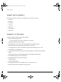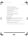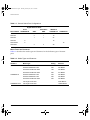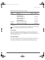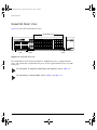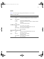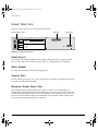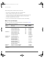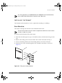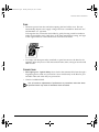
1
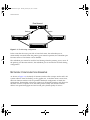
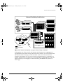
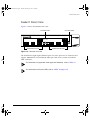
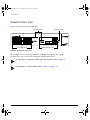
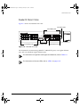
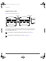
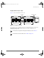
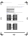
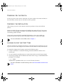
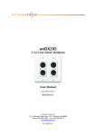
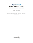
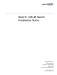
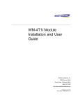
SummitInstall.book Page i Thursday, February 25, 1999 12:54 PM
Summit Hardware
Installation Guide
Extreme Networks, Inc.
10460 Bandley Drive
Cupertino, California 95014
(888) 257-3000
http://www.extremenetworks.com
Published: April 1999
Part number: 120087-00 Rev. A
SummitInstall.book Page ii Thursday, February 25, 1999 12:54 PM
Copyright © Extreme Networks, Inc., 1999. All rights reserved. No part of this documentation may be
reproduced in any form or by any means or used to make any derivative work (such as translation,
transformation, or adaptation) without permission from Extreme Networks, Inc.
Extreme Networks, ExtremeWare, ExtremeWare Vista, BlackDiamond, Summit, and the Extreme
Networks logo are trademarks of Extreme Networks.
ii
SummitInstall.book Page iii Thursday, February 25, 1999 12:54 PM
Contents
PREFACE
Introduction ix
Conventions x
Related Publications
1
xi
SUMMIT OVERVIEW
About the Summit Family of Switches 1-1
Summit Switch Models 1-2
Summary of Features 1-2
Port Connections 1-3
Media Types and Distances 1-4
Full-Duplex 1-5
Port Redundancy 1-5
Network Configuration Example 1-6
Summit1 Front View 1-9
Summit2 Front View 1-10
Summit3 Front View 1-11
Summit4 Front View 1-12
Summit4/FX Front View 1-13
Summit48 Front View 1-14
LEDs 1-15
Summit Rear View 1-16
Power Socket 1-16
Serial Number 1-16
Console Port 1-16
III
SummitInstall.book Page iv Thursday, February 25, 1999 12:54 PM
Redundant Power Supply Port
MAC Address 1-17
2
INSTALLATION
AND
1-16
SETUP
Following Safety Information 2-1
Determining the Switch Location 2-1
Media Types and Distances 2-2
Installing the Summit 2-3
Rack Mounting 2-3
Free-Standing 2-4
Stacking the Switch and Other Devices 2-4
Connecting Equipment to the Console Port 2-4
Powering On the Switch 2-6
Checking the Installation 2-6
Logging In for the First Time 2-6
A
SAFETY INFORMATION
Important Safety Information
Power A-1
Power Cord A-2
Fuse A-3
Connections A-3
Lithium Battery A-4
B
IV
TECHNICAL SPECIFICATIONS
A-1
SummitInstall.book Page v Thursday, February 25, 1999 12:54 PM
Figures
1-1
1-2
1-3
1-4
1-5
1-6
1-7
1-8
1-9
2-1
2-2
2-3
Dual-homing configuration 1-6
Network configuration using the Summit family of
switches 1-7
Summit1 front view 1-9
Summit2 front view 1-10
Summit3 front view 1-11
Summit4 front view 1-12
Summit4/FX front view 1-13
Summit48 front view 1-14
Summit rear view 1-16
Fitting the mounting bracket 2-3
Null-modem cable pin-outs 2-5
PC-AT serial null-modem cable pin-outs 2-5
V
SummitInstall.book Page vi Thursday, February 25, 1999 12:54 PM
VI
SummitInstall.book Page vii Thursday, February 25, 1999 12:54 PM
Tables
1
2
1-1
1-2
1-3
2-1
2-2
Notice Icons x
Text Conventions
xi
Summit Switch Port Configurations
Media Types and Distances
1-4
Summit LEDs
1-15
Media Types and Distances
2-2
Console Connector Pin-Outs 2-5
1-4
VII
SummitInstall.book Page viii Thursday, February 25, 1999 12:54 PM
VIII
SummitInstall.book Page ix Thursday, February 25, 1999 12:54 PM
Preface
This Preface provides an overview of this guide, describes guide conventions, and lists
other publications that may be useful.
INTRODUCTION
This guide provides the required information to install the Summit™ switch.
This guide is intended for use by network administrators who are responsible for
installing and setting up network equipment. It assumes a basic working knowledge of
• LLocal area networks (LANs)
• Ethernet concepts
• Ethernet switching and bridging concepts
• Routing concepts
• Internet Protocol (IP) concepts
• Routing Information Protocol (RIP) and Open Shortest Path First (OSPF)
• IP Multicast concepts
• Distance Vector Multicast Routing Protocol (DVMRP) concepts
• Protocol Independent Multicast-Dense Mode (PIM-DM) concepts
SUMMIT HARDWARE INSTALLATION GUIDE
IX
SummitInstall.book Page x Thursday, February 25, 1999 12:54 PM
PREFACE
• Internet Packet Exchange (IPX) concepts
• Simple Network Management Protocol (SNMP)
For information on configuring the Summit switch, refer to the ExtremeWare Software
User Guide.
If the information in the “Release Notes” shipped with your switch differs from the
information in this guide, follow the “Release Notes.”
CONVENTIONS
Table 1 and Table 2 list conventions used throughout this guide.
Table 1: Notice Icons
Icon
X
Notice Type
Alerts you to...
Note
Important features or instructions.
Caution
Risk of personal injury, system damage,
or loss of data.
Warning
Risk of severe personal injury.
SUMMIT HARDWARE INSTALLATION GUIDE
SummitInstall.book Page xi Thursday, February 25, 1999 12:54 PM
RELATED PUBLICATIONS
Table 2: Text Conventions
Convention
Description
Screen displays
This typeface represents information as it appears on the screen,
or command syntax.
Screen displays bold
This typeface represents commands that you type.
The words “enter”
and “type”
When you see the word “enter” in this guide, you must type
something, and then press the Return or Enter key. Do not press
the Return or Enter key when an instruction simply says “type.”
[Key] names
Key names appear in text in one of two ways:
■
Referred to by their labels, such as “the Return key” or “the
Escape key”
■
Written with brackets, such as [Return] or [Esc]
If you must press two or more keys simultaneously, the key
names are linked with a plus sign (+). Example:
Press [Ctrl]+[Alt]+[Del].
Words in italicized type
Italics emphasize a point or denote new terms at the place where
they are defined in the text.
RELATED PUBLICATIONS
The following is a list of related publications:
• ExtremeWare Software User Guide
• ExtremeWare Command Reference
• ExtremeWare Quick Reference Guide
• ExtremeWare “Release Notes”
• BlackDiamond Hardware Installation Guide
Documentation for Extreme Networks products is available on the World Wide Web at
the following location:
• Extreme Networks home page http://www.extremenetworks.com/
SUMMIT HARDWARE INSTALLATION GUIDE
XI
SummitInstall.book Page xii Thursday, February 25, 1999 12:54 PM
PREFACE
XII
SUMMIT HARDWARE INSTALLATION GUIDE
SummitInstall.book Page 1 Thursday, February 25, 1999 12:54 PM
1
Summit Overview
This chapter describes the following:
• Summit switch models
• Summit features
• How to use the Summit family of switches in your network configuration
• Summit front views
• Summit rear view
• Summit LEDs
• Factory default settings
ABOUT
THE
SUMMIT FAMILY
OF
SWITCHES
Network managers are currently faced with the challenge of creating networks that can
provide ultra-fast speed and high performance to serve the needs of today’s network
users, while simultaneously preserving the investment they have made in Ethernet and
Fast Ethernet technology.
By addressing the entire spectrum of Ethernet data rates (10/100/1000 Mbps), the
Summit family of LAN switches enables you to introduce high-speed Gigabit Ethernet
backbones into your existing network, while maintaining established connections to the
10 Mbps and 100 Mbps segments that already exist.
SUMMIT HARDWARE INSTALLATION GUIDE
1-1
SummitInstall.book Page 2 Thursday, February 25, 1999 12:54 PM
SUMMIT OVERVIEW
SUMMIT SWITCH MODELS
The Summit family of switches is comprised of six models, as follows:
• Summit1
• Summit2
• Summit24
• Summit3
• Summit4
• Summit4/FX
• Summit48
SUMMARY
OF
FEATURES
Summit switches support the following features:
• Fully nonblocking operation
— All ports transmit and receive packets at wire speed
• Optional redundant power supply
• 128K addresses in the switch forwarding database in bridging mode
• Redundant physical Gigabit Ethernet backbone connection
• Autonegotiation for half- or full-duplex operation (Fast Ethernet ports, only)
• Load-sharing on multiple ports
• Virtual local area networks (VLANs) including support for IEEE 802.1Q and IEEE
802.1p
• Spanning Tree Protocol (STP) (IEEE 802.1D) with multiple STP domains
• Policy-Based Quality of Service (PB-QoS)
• Wire-speed Internet Protocol (IP) routing
• IP Multinetting
• DHCP/BOOTP Relay
• Routing Information Protocol (RIP) version 1 and RIP version 2
• Open Shortest Path First (OSPF) routing protocol
1-2
SUMMIT HARDWARE INSTALLATION GUIDE
SummitInstall.book Page 3 Thursday, February 25, 1999 12:54 PM
SUMMARY
OF
FEATURES
• Wire-speed IP multicast routing support
• IGMP snooping to control IP multicast traffic
• Distance Vector Multicast Routing Protocol (DVMRP)
• Protocol Independent Multicast-Dense Mode (PIM-DM)
• IPX, IPX/RIP, and IPX/SAP support
• Load sharing on multiple ports
• Console command-line interface (CLI) connection
• Telnet CLI connection
• ExtremeWare Vista Web-based management interface
• Simple Network Management Protocol (SNMP) support
• Remote Monitoring (RMON)
• Traffic mirroring for all ports
PORT CONNECTIONS
The major difference between the models of the Summit switch is the port
configurations on each switch model. Summit switches use a combination of the
following types of ports:
• Fixed 1000BASE-SX ports using 850nm duplex SC connectors
• Modular 1000BASE-LX and 1000BASE-LX10 using Gigabit Interface Connectors
(GBICs)
• 10BASE-T/100BASE-TX ports using standard RJ-45 connectors
• 100BASE-FX ports using standard SC connectors
Table 1-1 describes port configurations available on the different Summit switch models.
SUMMIT HARDWARE INSTALLATION GUIDE
1-3
SummitInstall.book Page 4 Thursday, February 25, 1999 12:54 PM
SUMMIT OVERVIEW
Table 1-1: Summit Switch Port Configurations
Gigabit Ethernet Ports
Switch Model
Fixed
1000BASE-SX
GBIC
6
2
Summit1
Redundant
GBIC
10BASE-T/
100BASE-TX
Summit2
2
1
16
Summit3
1
1
24
Summit4
6
Summit4/FX
6
Summit48
MEDIA TYPES
16
16
2
AND
100BASE-FX
2
48
DISTANCES
Table 1-2 describes the media types and distances for the different types of Summit
ports.
Table 1-2: Media Types and Distances
Standard
Media Type
Mhz/Km
Rating
Maximum
Distance
1000BASE-SX
50/125um Multimode Fiber
400
500 Meters
50/125um Multimode Fiber
500
550 Meters
62.5/125um Multimode Fiber
160
220 Meters
62.5/125um Multimode Fiber
200
275 Meters
50/125um Multimode Fiber
400
550 Meters
50/125um Multimode Fiber
500
550 Meters
62.5/125um Multimode Fiber
500
550 Meters
1000BASE-LX
1000BASE-LX10*
1-4
10u Single-mode Fiber
5,000 Meters
10u Single-mode Fiber
10,000 Meters
SUMMIT HARDWARE INSTALLATION GUIDE
SummitInstall.book Page 5 Thursday, February 25, 1999 12:54 PM
SUMMARY
OF
FEATURES
Table 1-2: Media Types and Distances (continued)
Mhz/Km
Rating
Maximum
Distance
Standard
Media Type
100BASE-FX
50/125um Multimode Fiber
(half-duplex operation
400 Meters
50/125um Multimode Fiber
(full-duplex operation)
2000 Meters
62.5/125um Multimode Fiber
(half-duplex operation)
400 Meters
52.5/125um Multimode Fiber
(full-duplex operation)
2000 Meters
100BASE-TX
Category 5 UTP Cable (100Mbps)
100 Meters
10BASE-T
Category 3 UTP Cable (10Mbps)
100 Meters
*EXTREME NETWORKS
OF 5,000 METERS.
PROPRIETARY.
CAN
BE CONNECTED TO
1000BASE-LX
ON SINGLE-MODE FIBER USING A MAXIMUM DISTANCE
For more information on 1000BASE-SX and 1000BASE-LX link characteristics,
refer to IEEE Draft P802.3z/D4.2, Table 38-2 and Table 38-6.
FULL-DUPLEX
The Summit switch provides full-duplex support for all ports. Full-duplex allows
frames to be transmitted and received simultaneously and, in effect, doubles the
bandwidth available on a link. All 10/100 Mbps ports on the Summit autonegotiate for
half- or full-duplex operation.
PORT REDUNDANCY
The Summit2, Summit3, and Summit48 have an optional redundant Gigabit Ethernet
port. Using the redundant port, you can dual-home these models to one or two
switches. Figure 1-1 illustrates a Summit2 dual-homed to two different switches.
SUMMIT HARDWARE INSTALLATION GUIDE
1-5
SummitInstall.book Page 6 Thursday, February 25, 1999 12:54 PM
SUMMIT OVERVIEW
Dual-homed
Backup
Active
Figure 1-1: Dual-homing configuration
In the event that the active port fails or loses link status, the redundant port is
automatically activated. When the primary port resumes operation, the redundant port
becomes inactive. This feature can be disabled.
The redundant port cannot be used for load sharing when the primary port is active. If
the primary port becomes inactive, the redundant port is activated in the load sharing
configuration.
NETWORK CONFIGURATION EXAMPLE
As shown in Figure 1-2, the family of Summit switches offer a unique end-to-end LAN
system solution. From the desktop, to the gigabit core, to the data center/server farm,
there are Summit switches with an optimized hardware configuration to match the
requirements. ExtremeWare software is common to all Summit switches, and allows for
the same services to operate across the entire product family. All Summit switches
deliver wire-speed throughput and end-to-end policy based Quality of Service.
1-6
SUMMIT HARDWARE INSTALLATION GUIDE
SummitInstall.book Page 7 Thursday, February 25, 1999 12:54 PM
NETWORK CONFIGURATION EXAMPLE
Intranet Switching Architecture
Desktop switches
Segment switches
Desktop switches
Routers
Data Center
Gigabit
10/100 Mbps
Integrated Server switch
L2/L3
Figure 1-2: Network configuration using the Summit family of switches
In the gigabit core of the network, the Summit1 and Summit2 act as aggregators of
Gigabit Ethernet links from the edge and data center switches, as well as Ethernet and
Fast Ethernet links from legacy routers and hubs. In the core of the network, the
Summit1 and Summit2 can scale in port density and performance by connecting to a
Summit Virtual Chassis to support up to 32 non-blocking Gigabit Ethernet ports at 48
million packets per second (pps), or 128 non-blocking 10/100BASE-TX ports at 19
million pps.
SUMMIT HARDWARE INSTALLATION GUIDE
1-7
SummitInstall.book Page 8 Thursday, February 25, 1999 12:54 PM
SUMMIT OVERVIEW
In the data center or server farm, the Summit4 offers the right mix of ports and features
for servers. Data centers and server farms require integrated wire-speed routing to
eliminate the performance penalty associated with legacy routers when servers had to
be separated into different subnets. In addition, the Summit4 supports trunking of
either Ethernet, Fast Ethernet, or Gigabit Ethernet ports to match the performance of the
LAN connection to the performance of the server. The goal is to only buy the amount of
bandwidth that is needed and can be used. This is ideal for servers that can drive 400
Mbps on trunk Fast Ethernet ports, but would not be capable of more than 400 Mbps
performance on a Gigabit Ethernet port. The port density and performance of the
Summit4 can be scaled with the Summit Virtual Chassis to 16 Gigabit Ethernet ports,
and 128 10/100BASE-TX ports at 43 million pps.
At the edge of the network, higher-performance desktops need dedicated throughput,
while other devices can use small, shared segments. For higher-performance
connections, use the Summit3 and Summit48 switches (which offer 24 10/100BASE-TX
ports) and a single Gigabit Ethernet port, or 48 10/100BASE-TX ports and two Gigabit
Ethernet ports, respectively. For shared desktop segments, the Summit2 offers 16
10/100BASE-TX ports and two Gigabit Ethernet ports. Combining the Summit3 and the
Summit48 with the Summit Virtual Chassis, desktop switching port densities can scale
to 192 10/100BASE-TX ports at 28 million pps, and 384 10/100BASE-TX ports at 28
million pps, respectively.
1-8
SUMMIT HARDWARE INSTALLATION GUIDE
SummitInstall.book Page 9 Thursday, February 25, 1999 12:54 PM
SUMMIT1 FRONT VIEW
SUMMIT1 FRONT VIEW
Figure 1-3 shows the Summit1 front view.
Port status LEDs
Unit status LEDs
1
8
AMBER
= ACTIVITY
GREEN
= LINK OK
FLASHING GREEN = DISABLED
ACTIVITY
2
3
4
Gigabit Ethernet ports
1
2
9
10 11 12 13 14 15 16
3
4
5
LINK
6
7
8
5
6
7
Gigabit Ethernet ports
Figure 1-3: Summit1 front view
The Summit1 has eight Gigabit Ethernet ports. Six of the ports use SC connectors and
support 1000BASE-SX over multimode fiber-optic cable. Ports 1 and 8 use modular
GBIC connectors.
For information on supported media types and distances, refer to Table 1-2.
For information on Summit LEDs, refer to “LEDs,” on page 1-15.
SUMMIT HARDWARE INSTALLATION GUIDE
1-9
SummitInstall.book Page 10 Thursday, February 25, 1999 12:54 PM
SUMMIT OVERVIEW
SUMMIT2 FRONT VIEW
Figure 1-4 shows the Summit2 front view.
Port status LEDs
1
2
3
4
5
6
7
Unit status LEDs
18
8
AMBER
= ACTIVITY
GREEN
= LINK OK
FLASHING GREEN = DISABLED
9
10
11
12
13
14
15
16
10/100 Mbps ports
1
2
9
10 11 12 13 14 15 16
3
4
5
6
7
8
17R
17
Gigabit Ethernet ports
Figure 1-4: Summit2 front view
The Summit2 has 16 autosensing 10BASE-T/100BASE-TX ports and two Gigabit
Ethernet ports, one of which has a redundant Gigabit Ethernet port.
For information on supported media types and distances, refer to Table 1-2.
For information on Summit LEDs, refer to “LEDs,” on page 1-15.
1-10
SUMMIT HARDWARE INSTALLATION GUIDE
SummitInstall.book Page 11 Thursday, February 25, 1999 12:54 PM
SUMMIT3 FRONT VIEW
SUMMIT3 FRONT VIEW
Figure 1-5 shows the Summit3 front view.
Unit status LEDs
10/100 Mbps ports
1
2
3
4
5
6
7
17
8
18
19
20
21
22
23
24
AMBER
= ACTIVITY
GREEN
= LINK OK
FLASHING GREEN = DISABLED
9
10
11
12
13
14
15
16
10/100 Mbps ports
1
2
9
10 11 12 13 14
15 16
25 25 ACTIVITY
17 18 19 20 21 22
3
4
5
6
23 24
7
8
25 25 LINK
R
Port status LEDs
25R
25
Gigabit Ethernet ports
Figure 1-5: Summit3 front view
The Summit3 has 24 autosensing 10BASE-T/100BASE-TX ports, one Gigabit Ethernet
port, and one redundant Gigabit Ethernet port.
For information on supported media types and distances, refer to Table 1-2.
For information on Summit LEDs, refer to “LEDs,” on page 1-15.
SUMMIT HARDWARE INSTALLATION GUIDE
1-11
SummitInstall.book Page 12 Thursday, February 25, 1999 12:54 PM
SUMMIT OVERVIEW
SUMMIT4 FRONT VIEW
Figure 1-6 shows the Summit4 front view.
10/100 Mbps ports
1
2
3
4
5
6
Unit status LEDs
Port status
LEDs
7
8
AMBER
= ACTIVITY
GREEN
= LINK OK
FLASHING GREEN = DISABLED
1
2
9
10 11 12 13 14
3
4
5
6
7
10/100 Mbps ports
9
10
11
12
13
14
15
16
8
15 16
ACTIVITY
17 18 19 20 21 22
17 18 19 20 21 22
17
18
19
Gigabit Ethernet ports
LINK
20
21
22
Gigabit Ethernet ports
Figure 1-6: Summit4 front view
The Summit4 has 16 autosensing 10BASE-T/100BASE-TX ports and 6 Gigabit Ethernet
ports. The Gigabit Ethernet ports use standard SC connectors and support 1000BASE-SX
over multimode fiber-optic cable.
For information on supported media types and distances, refer to Table 1-2.
For information on Summit LEDs, refer to “LEDs,” on page 1-15.
1-12
SUMMIT HARDWARE INSTALLATION GUIDE
SummitInstall.book Page 13 Thursday, February 25, 1999 12:54 PM
SUMMIT4/FX FRONT VIEW
SUMMIT4/FX FRONT VIEW
Figure 1-7 shows the Summit4/FX front view.
100 Mbps ports
1
2
Unit status LEDs
Port status
LEDs
3
4
100 Mbps ports
5
6
7
8
13
14
15
16
FLASHING AMBER = TRAFFIC
SOLID AMBER
= DISABLED
GREEN
= ENABLED, LINK OK
9
10
1
11
2
1
2
9
10 11 12 13 14
3
12
4
5
6
7
2
1
2
3
Gigabit Ethernet ports
3
4
5
6
3
4
5
6
ACTIVITY
8
15 16
LINK
1
4
5
6
Gigabit Ethernet ports
Figure 1-7: Summit4/FX front view
The Summit4/FX has 16 100BASE-FX ports and 6 Gigabit Ethernet ports. All ports use
standard SC connectors. The Gigabit Ethernet ports support 1000BASE-SX over
multimode fiber-optic cable.
For information on supported media types and distances, refer to Table 1-2.
For information on Summit LEDs, refer to “LEDs,” on page 1-15.
SUMMIT HARDWARE INSTALLATION GUIDE
1-13
SummitInstall.book Page 14 Thursday, February 25, 1999 12:54 PM
SUMMIT OVERVIEW
SUMMIT48 FRONT VIEW
Figure 1-8 shows the Summit48 front view.
10/100 Mbps ports
1
2
3
4
5
7
8
9
10 11 12
1
2
3
4
5
6
7
8
9
10
11
12
13
25
14
26
15
27
16
28
17
29
18
30
19
31
20
32
21
33
22
34
23
35
24
36
37
38
39
40
41
42
43
44
45
46
47
48
6
A 49 49R 13 14 15 16 17 18
L 49 49R 19 20 21 22 23 24
49
49R
1000 BASE-X
= ACTIVITY
AMBER
= LINK OK
GREEN
FLASHING GREEN = DISABLED
10/100 BASE-X
MDI-X
25 26 27 28 29 30
Power
31 32 33 34 35 36
A 50 50R 37 38 39 40 41 42
Mgmt.
L 50 50R 43 44 45 46 47 48
50
50R
Gigabit Ethernet
ports
Port status
LEDs
Unit status
LEDs
Figure 1-8: Summit48 front view
The Summit48 has 48 autosensing 10BASE-T/100BASE-TX ports, 2 Gigabit Ethernet
ports, and 2 redundant Gigabit Ethernet ports. All the Gigabit Ethernet ports use GBIC
connectors.
For information on supported media types and distances, refer to Table 1-2.
For information on Summit LEDs, refer to “LEDs,” on page 1-15.
1-14
SUMMIT HARDWARE INSTALLATION GUIDE
SummitInstall.book Page 15 Thursday, February 25, 1999 12:54 PM
LEDS
LEDS
Table 1-3 describes the light emitting diode (LED) behavior on the Summit.
Table 1-3: Summit LEDs
LED
Color
Indicates
Power
Green
The Summit is powered up.
Yellow
The Summit is indicating a power, overheat, or fan failure.
MGMT
Green flashing
■
Slow
The Summit is operating normally.
■
Fast
Power On Self Test (POST) in progress, or software download
in progress.
Yellow
The Summit has failed its POST.
10/100Mbps Port Status LEDs
Green
Link is present; port is enabled.
Yellow
Frames are being transmitted/received on this port.
Green flashing
Link is present; port is disabled.
Off
Link is not present.
Gigabit Ethernet Port Status LEDs
Packet
Status
Yellow
Frames are being transmitted/received on this port.
Off
No activity on this port.
Green on
Link is present; port is enabled;
full-duplex operation.
Green flashing
Link is present; port is disabled.
Off
Link is not present.
SUMMIT HARDWARE INSTALLATION GUIDE
1-15
SummitInstall.book Page 16 Thursday, February 25, 1999 12:54 PM
SUMMIT OVERVIEW
SUMMIT REAR VIEW
Figure 1-9 shows the rear view for the Summit switch.
Power socket and fuse
U
L
RPS port
C
Console port
U
L
!
MODEL/NUMBER
MADE IN USA
PART NUMBER
SERIAL NUMBER
MAC ADDRESS
130001-00 Rev.03
Figure 1-9: Summit rear view
POWER SOCKET
The Summit automatically adjusts to the supply voltage. The power supply operates
down to 90 V. The fuse is suitable for both 110 V AC and 220-240 V AC operation.
SERIAL NUMBER
Use this serial number for fault-reporting purposes.
CONSOLE PORT
Use the console port (9-pin, “D” type connector) for connecting a terminal and carrying
out local out-of-band management.
REDUNDANT POWER SUPPLY PORT
The redundant power supply (RPS) port is used to connect to a Summit RPS or a
Summit Virtual Chassis. Both the Summit RPS and the Summit Virtual Chassis provide
a redundant, load-shared power source to the Summit. If the primary power source for
the switch fails, the RPS in either the Summit RPS or the Summit Virtual Chassis takes
over, ensuring uninterrupted network operation.
1-16
SUMMIT HARDWARE INSTALLATION GUIDE
SummitInstall.book Page 17 Thursday, February 25, 1999 12:54 PM
SUMMIT REAR VIEW
In addition, when connected to a Summit RPS or Summit Virtual Chassis, the Summit
switch can provide status on power and fan operation of the RPS through SNMP, the
command-line interface, and the Web interface (power supply status only).
The Summit RPS and Summit Virtual Chassis can simultaneously provide power for as
many as two Summit switches.
MAC ADDRESS
This label shows the unique Ethernet MAC address assigned to this device.
SUMMIT HARDWARE INSTALLATION GUIDE
1-17
SummitInstall.book Page 18 Thursday, February 25, 1999 12:54 PM
SUMMIT OVERVIEW
1-18
SUMMIT HARDWARE INSTALLATION GUIDE
SummitInstall.book Page 1 Thursday, February 25, 1999 12:54 PM
2
Installation and Setup
This chapter describes the following:
• How to decide where to install the Summit
• Gigabit Ethernet configuration rules
• How to install the switch in a rack or free-standing
• How to connect equipment to the console port
• How to check the installation using the Power On Self-Test (POST)
FOLLOWING SAFETY INFORMATION
Before installing or removing any components of the switch, or before carrying out any
maintenance procedures, you must read the safety information provided in Appendix A
of this guide.
DETERMINING
THE
SWITCH LOCATION
The Summit is suited for use in the office, where it can be free-standing or mounted in a
standard 19-inch equipment rack. Alternatively, the device can be rack-mounted in a
wiring closet or equipment room. Two mounting brackets are supplied with the switch.
SUMMIT HAREWARE INSTALLATION GUIDE
2-1
SummitInstall.book Page 2 Thursday, February 25, 1999 12:54 PM
INSTALLATION
AND
SETUP
When deciding where to install the switch, ensure that:
• The switch is accessible and cables can be connected easily.
• Water or moisture cannot enter the case of the unit.
• Air-flow around the unit and through the vents in the side of the case is not
restricted. You should provide a minimum of 25mm (1-inch) clearance.
• No objects are placed on top of the unit.
• Units are not stacked more than four high if the switch is free-standing.
MEDIA TYPES
AND
DISTANCES
The connectors, media types, and maximum distances are described in Table 2-1.
Table 2-1: Media Types and Distances
Standard
Media Type
Mhz/Km
Rating
Maximum
Distance
1000BASE-SX
50/125um Multimode Fiber
400
500 Meters
50/125um Multimode Fiber
500
550 Meters
62.5/125um Multimode Fiber
160
220 Meters
62.5/125um Multimode Fiber
200
275 Meters
50/125um Multimode Fiber
400
550 Meters
50/125um Multimode Fiber
500
550 Meters
62.5/125um Multimode Fiber
500
550 Meters
1000BASE-LX
10u Single-mode Fiber
5,000 Meters
1000BASE-LX10*
10u Single-mode Fiber
10,000 Meters
100BASE-FX
50/125um Multimode Fiber
(half-duplex operation
400 Meters
50/125um Multimode Fiber
(full-duplex operation)
2000 Meters
62.5/125um Multimode Fiber
(half-duplex operation)
400 Meters
52.5/125um Multimode Fiber
(full-duplex operation)
2000 Meters
100BASE-TX
Category 5 UTP Cable (100Mbps)
100 Meters
10BASE-T
Category 3 UTP Cable (10Mbps)
100 Meters
*EXTREME NETWORKS
OF 5,000 METERS.
2-2
PROPRIETARY.
CAN
BE CONNECTED TO
1000BASE-LX
ON SINGLE-MODE FIBER USING A MAXIMUM DISTANCE
SUMMIT HAREWARE INSTALLATION GUIDE
SummitInstall.book Page 3 Thursday, February 25, 1999 12:54 PM
INSTALLING
THE
SUMMIT
For more information on 1000BASE-SX and 1000BASE-LX link characteristics,
refer to IEEE Draft P802.3z/D4.2, Table 38-2 and Table 38-6.
INSTALLING
THE
SUMMIT
The Summit can be mounted in a rack, or placed free-standing on a tabletop.
RACK MOUNTING
The switch is 2U high and will fit in most standard 19-inch racks.
The rack mount kits must not be used to suspend the switch from under a table
or desk, or attach it to a wall.
To rack mount the Summit, follow these steps:
1 Place the switch the right way up on a hard flat surface, with the front facing toward
you.
2 Remove the existing screws from the sides of the chassis and retain for Step 4.
3 Locate a mounting bracket over the mounting holes on one side of the unit.
4 Insert the four screws and fully tighten with a suitable screwdriver, as shown in
Figure 2-1.
Figure 2-1: Fitting the mounting bracket
SUMMIT HAREWARE INSTALLATION GUIDE
2-3
SummitInstall.book Page 4 Thursday, February 25, 1999 12:54 PM
INSTALLATION
AND
SETUP
5 Repeat the three previous steps for the other side of the switch.
6 Insert the switch into the 19-inch rack and secure with suitable screws (not
provided). Ensure that ventilation holes are not obstructed.
7 Connect the Summit to the redundant power supply (if applicable).
8 Connect cables.
FREE-STANDING
The Summit is supplied with four self-adhesive rubber pads. Apply the pads to the
underside of the device by sticking a pad in the marked area at each corner of the
switch.
STACKING
THE
SWITCH
AND
OTHER DEVICES
Up to four Summit switches can be placed on top of one another.
This section relates only to physically placing the devices on top of one another.
Apply the pads to the underside of the device by sticking a pad at each corner of the
switch. Place the devices on top of one another, ensuring that the corners align.
CONNECTING EQUIPMENT
TO THE
CONSOLE PORT
Connection to the console port is used for direct local management. The switch console
port settings are set as follows:
• Baud rate — 9600
• Data bits — 8
• Stop bit — 1
• Parity — None
• Flow control — XON/XOFF
The terminal connected to the console port on the switch must be configured with the
same settings. This procedure will be described in the documentation supplied with the
terminal.
2-4
SUMMIT HAREWARE INSTALLATION GUIDE
SummitInstall.book Page 5 Thursday, February 25, 1999 12:54 PM
CONNECTING EQUIPMENT
TO THE
CONSOLE PORT
Appropriate cables are available from your local supplier. In order to make your own
cables, pin-outs for a DB-9 male console connector are described in Table 2-2.
Table 2-2: Console Connector Pin-Outs
Function
Pin Number
TXD (transmit data)
3
RXD (receive data)
2
GND (ground)
5
Figure 2-2 shows the pin-outs for a 9-pin to RS-232 25-pin null-modem cable.
Summit
PC/Terminal
Cable connector: 9-pin female
Cable connector: 25-pin male/female
Screen Shell
3
TxD
2
RxD
5
Ground
7
RTS
8
CTS
6
DSR
1
DCD
4
DTR
1
3
2
7
4
20
5
6
8
Screen
RxD
TxD
Ground
RTS
DTR
CTS
DSR
DCD
Figure 2-2: Null-modem cable pin-outs
Figure 2-3 shows the pin-outs for a 9-pin to 9-pin PC-AT null-modem serial cable.
Summit
PC-AT Serial Port
Cable connector: 9-pin female
Cable connector: 9-pin female
Screen Shell
4
DTR
3
TxD
2
RxD
8
CTS
5
Ground
6
DSR
7
RTS
1
DCD
Shell Screen
1
DCD
2
RxD
3
TxD
4
DTR
5
Ground
6
DSR
7
RTS
8
CTS
Figure 2-3: PC-AT serial null-modem cable pin-outs
SUMMIT HAREWARE INSTALLATION GUIDE
2-5
SummitInstall.book Page 6 Thursday, February 25, 1999 12:54 PM
INSTALLATION
AND
SETUP
POWERING ON
THE
SWITCH
To turn on power to the switch, connect the AC power cable to the switch and then to
the wall outlet, and turn the on/off switch to the on position.
CHECKING
THE INSTALLATION
After turning on power to the Summit, the device performs a Power On Self-Test
(POST).
During the POST, all ports are temporarily disabled, the packet LED is off, the power
LED is on, and the MGMT LED flashes. The MGMT LED flashes until the switch has
successfully passed the POST.
If the switch passes the POST, the MGMT LED blinks at a slow rate (1 blink per
second). If the switch fails the POST, the MGMT LED shows a solid yellow light.
For more information on the LEDs, refer to Chapter 1.
LOGGING IN
FOR THE
FIRST TIME
After the Summit has completed the POST, it is operational. Once operational, you can
log in to the switch and configure an IP address for the default VLAN (named default).
To manually configure the IP settings, perform the following steps:
1 Connect a terminal or workstation running terminal-emulation software to the
console port.
2 At your terminal, press [Return] one or more times until you see the login prompt.
3 At the login prompt, enter the default user name admin to log on with administrator
privileges. For example:
login: admin
Administrator capabilities allow you to access all switch functions.
For more information on switch security, refer to the ExtremeWare Software User
Guide.
2-6
SUMMIT HAREWARE INSTALLATION GUIDE
SummitInstall.book Page 7 Thursday, February 25, 1999 12:54 PM
LOGGING IN
FOR THE
FIRST TIME
4 At the password prompt, press [Return].
The default name, admin, has no password assigned. When you have successfully
logged on to the switch, the command-line prompt displays the name of the switch
(for example, Summit1) in its prompt.
5 Assign an IP address and subnetwork mask for VLAN default by typing
config vlan default ipaddress 123.45.67.8 255.255.255.0
Your changes take effect immediately.
6 Save your configuration changes so that they will be in effect after the next switch
reboot, by typing
save
For more information on saving configuration changes, refer to the ExtremeWare
Software User Guide.
7 When you are finished using the facility, logout of the switch by typing
logout
After two incorrect login attempts, the Summit locks you out of the login facility.
You must wait a few minutes before attempting to log in again.
SUMMIT HAREWARE INSTALLATION GUIDE
2-7
SummitInstall.book Page 8 Thursday, February 25, 1999 12:54 PM
INSTALLATION
2-8
AND
SETUP
SUMMIT HAREWARE INSTALLATION GUIDE
SummitInstall.book Page 1 Thursday, February 25, 1999 12:54 PM
A
Safety Information
IMPORTANT SAFETY INFORMATION
Please read the following safety information thoroughly before installing the
Summit switch.
• Installation and removal of the unit must be carried out by qualified personnel only.
• To reduce the risk of fire or electrical shock, install the unit in a temperature- and
humidity-controlled indoor area free of conductive contaminants.
POWER
• Disconnect power from the unit before removing the cover of the unit.
• To ensure compliance with international safety standards, only use the power
adapter that is supplied with the unit.
• Disconnect the power adapter before removing the unit.
• The unit must be grounded.
• The unit must be connected to a grounded outlet to comply with European safety
standards.
• Do not connect the unit to an A C outlet (power supply) without a ground
connection.
• The socket outlet must be near to the unit and easily accessible. You can only remove
power from the unit by disconnecting the power cord from the outlet.
SUMMIT HARDWARE INSTALLATION GUIDE
A-1
SummitInstall.book Page 2 Thursday, February 25, 1999 12:54 PM
SAFETY INFORMATION
• This unit operates under Safety Extra Low Voltage (SELV) conditions according to
IEC 950. The conditions are only maintained if the equipment to which it is
connected also operates under SELV conditions.
• The appliance coupler (the connector to the unit and not the wall plug) must have a
configuration for mating with an EN60320/IEC320 appliance inlet.
• France and Peru only
This unit cannot be powered from IT† supplies. If your supplies are of IT type, this
unit must be powered by 230V (2P+T) via an isolation transformer ratio 1:1, with the
secondary connection point labeled Neutral, connected directly to ground.
POWER CORD
• This must be approved for the country where it is used:
USA and
Canada
• The cord set must be UL-approved and CSAcertified.
• The minimum specification for the flexible cord is
No. 18 AWG, Type SV or SJ, 3-conductor.
• The cord set must have a rated current capacity of
at least 10A.
• The attachment plug must be an earth-grounding
type with a NEMA 5-15P (15A, 125V) or NEMA
6-15P (15A, 250V) configuration.
Denmark
• The supply plug must comply with section
107-2-D1, standard DK2-1a or DK2-5a.
Switzerland
• The supply plug must comply with SEV/ASE 1011.
• If the power cord plug is unsuitable and must be replaced, you may find other
codings for the respective connections. Connect the power supply wires for the unit
according to the following scheme:
— Brown wire to the Live (Line) plug terminal, which may be marked with the
letter “L” or colored red.
— Blue wire to the Neutral plug terminal, which may be marked with the letter “N”
or colored black.
— Yellow/Green wire to the Ground plug terminal, which may be marked with the
letter “E” or the Earth symbol
or colored yellow/green.
A-2
SUMMIT HARDWARE INSTALLATION GUIDE
SummitInstall.book Page 3 Thursday, February 25, 1999 12:54 PM
IMPORTANT SAFETY INFORMATION
FUSE
• Disconnect power from the unit before opening the fuse holder cover. The unit
automatically adjusts to the supply voltage. The fuse is suitable for both 110V A.C.
and 220-240V A.C. operation.
To change the fuse, release the fuse holder by gently levering a small screwdriver
under the fuse holder catch. Only fuses of the same manufacturer, rating, and type
as the original must be used with the unit. Close the fuse holder.
Fuse
• To comply with European safety standards, a spare fuse must not be fitted to the
appliance inlet. Only fuses of the same manufacturer, make, and type must be used
with the unit.
CONNECTIONS
• Fiber Optic ports - Optical Safety. Never look at the transmit LED/laser through a
magnifying device while it is powered on. Never look directly at the fiber TX port
and fiber cable ends when they are powered on.
• CLASS 1 LASER DEVICE
Use of controls or adjustments of performance or procedures other than those
specified herein may result in hazardous laser emissions.
SUMMIT HARDWARE INSTALLATION GUIDE
A-3
SummitInstall.book Page 4 Thursday, February 25, 1999 12:54 PM
SAFETY INFORMATION
LITHIUM BATTERY
• Replace the lithium battery with the same or equivalent type, as recommended by
the manufacturer.
There is a danger of explosion if the battery is incorrectly replaced.
•Dispose of used batteries according to the manufacturer’s instructions.
— Do not dispose of the batteries in water, or by fire.
— Disposal requirements vary by country and by state.
— Lithium batteries are not listed by the Environmental Protection Agency (EPA) as
a hazardous waste. Therefore, they can typically be disposed of as normal waste.
— If you are disposing of large quantities, contact a local waste-management
service.
• No hazardous compounds are used within the battery module.
• The weight of the lithium contained in each coin cell is approximately 0.035 grams.
• Two types of batteries are used interchangeably:
— CR chemistry uses manganese dioxide as the cathode material.
— BR chemistry uses poly-carbonmonofluoride as the cathode material.
• The battery in the bq4830 device is encapsulated and not user-replaceable.
A-4
SUMMIT HARDWARE INSTALLATION GUIDE
SummitInstall.book Page 1 Thursday, February 25, 1999 12:54 PM
B
Technical Specifications
Physical Dimensions
Height: 3.5 inches x Width: 17.32 inches x Depth: 17.32
inches
Weight: 10 kg
Environmental Requirements
Operating Temperature
0 to 40° C
Storage Temperature
-10 to 70 ° C
Operating Humidity
10% to 95% relative humidity, noncondensing
Standards
EN60068 (IEC68)
Safety
Agency Certifications
UL 1950 3rd Edition, listed
cUL listed to CSA 22.2#950
TUV GS mark & GOST safety approval to the following
EN standards:
Electromagnetic Compatibility
■
EN60960:1992/A3:1995 plus ZB/ZC Deviations
■
EN60825-1
FCC part 15 Class A
CSA C108.8-M11983 (A)
VCCI Class 2
EN55022 Class B
EN50082 -1 (1997)
C-Tick mark to AS/NZS 3548:1995
Summit products that have RJ-45 ports comply with EN55022 Class B when
used with shielded UTP cable.
SUMMIT HARDWARE INSTALLATION GUIDE
B-1
SummitInstall.book Page 2 Thursday, February 25, 1999 12:54 PM
TECHNICAL SPECIFICATIONS
Heat Dissipation
118W maximum (341.2 BTU/hr maximum)
Power Supply
AC Line Frequency
47Hz to 63Hz
Input Voltage Options
90VAC to 264VAC, auto-ranging
Current Rating
100-120/200-240 VAC 3.0/1.5 A
B-2
SUMMIT HARDWARE INSTALLATION GUIDE
SummitInstall.book Page i Thursday, February 25, 1999 12:54 PM
Index
C
P
cable types and distances 1-4, 2-2
console port 1-16
connecting equipment to 2-4
conventions
notice icons x
text xi
port
connections 1-3
console 1-16
redundant power supply 1-16
power socket 1-16
power supply 1-16
powering on the switch 2-6
F
free-standing installation 2-4
full-duplex 1-5
R
rack mounting the switch 2-3
redundant power supply port 1-16
reset button 1-16
H
hardware address 1-17
I
installing the switch 2-3
L
LED, description 1-15
location 1-16
logging in 2-6
M
MAC address 1-17
media types and distances 1-4, 2-2
S
safety information
English A-1
serial number 1-16
serial port. See console port
socket, power 1-16
Summit
configuration example 1-6
dimensions B-1
features 1-2
free-standing installation 2-4
installing 2-3
LEDs 1-15
MAC address 1-17
media distances, supported 1-4
media types, supported 1-4
models 1-2
port connections 1-3
SummitInstall.book Page ii Thursday, February 25, 1999 12:54 PM
positioning 2-1
powering on 2-6
rack mounting 2-3
rear view 1-16
size B-1
stacking with other devices 2-4
weight B-1
Summit1, front view 1-9
Summit2, front view 1-10
Summit3, front view 1-11
Summit4, front view 1-12
Summit4/FX, front view 1-13
Summit48, front view 1-14
V
verifying the installation 2-6
II
- INDEX