1
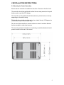
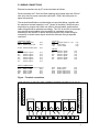
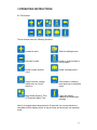
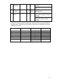
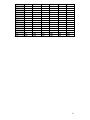
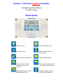
Autolux ~ Universal Lighting Controller
Installation and User Manual
for UNI/L version
Quick Guide
Increase a value.
Enter the settings menu.
Decrease a value.
Initiate or quickly extend a
time program.
Accept a newly entered value.
Initiate a holiday period.
Cancel overtime, holiday,
edited value or current
submenu.
End overtime, holiday or reset
time logs in engineers menu.
Apply British Summer Time or
Greenwich Mean Time.
Toggle the display between
time and sensor readings
Autolux ~ Universal Lighting Controller
Installation and User Manual
CONTENTS
Introduction .............................................................................3
1 Technical Specifications .............…..............................….. 3
1.1 Operating Environment .................................................….. 3
1.2 Performance Specifications .……………............................. 3
1.3 Electrical Specifications ………………….........…………......4
2 Installation Instructions ........................................……....... 5
2.1 Mounting the Control Assembly .................. ………….........5
2.2 General Wiring Specifications ........................………………7
2.3 Wiring Connections .………………….......... ..........…………8
2.4 Occupancy Sensor Wiring Connections…………..…………9
2.5 Light Level Sensor Wiring Connections …..…………………9
2.6 Remote Switch Wiring Connections ……… ………………..10
2.7 Remote Panic Switch Wiring Connections …..……………..10
3 Operating Instructions ....................….......................……...11
3.1 The buttons .......................................................…………... 11
3.2 The display … .........................................................………. 12
3.3 Remote equipment……….. ................................................ 12
3.4 Setting User Parameters…………………………………….. 13
3.5 Setting the Clock …………………………………………….. 13
3.6 Setting the Auto Mode ……………………………………….. 14
3.7 Setting the Program (on / off times)………………………… 15
3.8 Setting the Lux level ………………………………………….. 16
3.9 Setting BST / GMT ……………………………………………. 16
3.10 Setting the Extend feature……………………………………17
3.11 Setting holiday…………………………………………………18
3.12 Viewing info…………………………………………………… 18
4 Engineer Functions ..................................................…....... 20
4.1 General Password (PIN protection).........…………………...20
4.2 Programming the engineering functions........……………….21
2
Autolux ~ Universal Lighting Controller
Installation and User Manual
INTRODUCTION
This manual describes the Installation and Operation of the Autolux ~
Universal Lighting Controller
This control must be installed according to the current IEE Wiring Regulations
and should include full disconnection means and fusing appropriate to the
connected loads.
1 TECHNICAL SPECIFICATIONS
1.1 Operating Environment
1.2 Performance Specifications
Operating temperature range:
0º C to 40º C
An independently mounted
electronic control for surface
mounting.
Operating humidity range:
0 to 90% RH.
Control IP rating:
IP30
Operation is by Class A software
and Type 1A action.
The mains supply to the electronic
circuit is to be protected by a fuse.
Pollution degree:
II environment
Control safety construction:
Class II
Remote switch inputs will be volt
free, 12Vdc/5mA
Mains supply:
230Vac nominal, 200Vac to
265Vac actual, 50Hz.
Occupancy sensor inputs are volt
free, normally closed (contacts
open on detection of occupancy) as
BW/MINI, BW/35, BW/CUR,
BW/MW and PIR/CM.
On board supply fuse: 1AT
Maximum sensor rating: 90 mA
Rated impulse voltage: 2500V
Recommended control supply fuse:
3A
Rated impulse voltage: 2500V
Dimensions: 216mm X 124mm X
62mm
Conformities: EMC – 89/336/EEC
LVD – 73/23/EEC
Push switch inputs are volt free,
normally closed (push to break).
Lux sensor readings are from a
photo-diode, operating at 12v dc as
UNI/LUX or UNI/LUX/WP.
Panic switch input is volt free,
normally open (contacts make for
panic operation)
Temperature sensor input is from a
thermistor sensor, as UNI/RS
.
3
1.3 Electrical Specifications
The power supply is SELV isolated, therefore all remote sensor and remote
switch wiring to the control does not need to be mains level rated, but should
be insulated to the highest voltage present where entering the control box.
Relay 1 is rated
16A/240Vac resistive
6A/240Vac inductive / fluorescent
3A/240Vac compact fluorescent
Relay 2 is rated
16A/240Vac resistive
6A/240Vac inductive / fluorescent
3A/240Vac compact fluorescent
Relays 1 and 2 are rated
16A/240Vac resistive
6A/240Vac inductive / fluorescent
3A/240Vac compact fluorescent.
Total maximum load for relays 1
and 2 is 12A.
Relays 3 to 7 are rated
10A/240Vac resistive
4A/240Vac inductive / fluorescent
2A/240Vac compact fluorescent.
Maximum load for each of relays
3 and 4 is 6A.
Total maximum load for relays 5
to 7 is 12A.
Generally, it is recommended that
the relays are used to operate
contactor relays. Using the
engineers menu, the relays can be
assigned en-masse to control
either as contacts open for lighting
on (normally closed contactors
required for fail safe operation) or
contacts close for lighting on
(normally open contactors
required).
0 – 10V signals:
A 0 to 10Vdc output signal is
provided for dimming control.
Output impedance is 50 Ohm and
maximum current drive capacity is
5mA. The output signal is not
isolated from the control circuit but
the common ground may be
Earthed.
Sensors can be sited up to 100m
from the control; the cable
may be screened to improve noise
rejection. Cable resistance must be
less than 10 Ohms to minimise
errors.
4
2 INSTALLATION INSTRUCTIONS
2.1 Mounting the Control Assembly
Ensure that the controller is installed no less than 1.5m above the floor level.
The controller should be positioned to allow the user easy access to the push
buttons and to read the LCD display.
The controller can be positioned with the cable entry to the bottom or the top
depending on the cable routing.
The lid with the controller circuit board can be rotated through 180 degrees to
accommodate top or bottom cable entry.
Do not mount the controller on a warm surface or where it could be affected
by direct sunlight or other heat sources.
The mounting surface should be non-conducting or earth bonded and should
prevent access to the rear of the control.
5
The housing consists of a two
part plastic moulding held
together by four screws.
Plugs are supplied to cover
the screws following
installation.
Knockouts are provided for cable
glands to allow mains and remote
sensor and switch cables to be
fitted to the control assembly.
Knock the plastic out to
fit the glands as required. Never
leave holes that allow finger
access.
Whenever possible, keep mains wiring and signal wiring separated and use
separate knockouts for each type of wiring system. Consider the termination
points when selecting the appropriate knockouts.
6
2.2 General Wiring Specifications
Connect as shown below.
A suitably qualified person must make all wiring connections.
Please refer to the following wiring connection drawings (see 2.3) and
observe the notes referring to cable type and length. Failure to follow these
guidelines may result in electrical interference or unsatisfactory operation.
When making connections to screw terminals please ensure that no more
than 6mm of insulation is stripped back and that no stray wire strands escape.
0-12V outputs, Analogue 0 – 10V output and remote switch inputs for
occupancy, push switch and panic switch should be connected by 0.75mm2
cable of maximum length 100m.
The remote light level sensor(s) and remote temperature sensor can be sited
up to 100m from the control; the cable may be screened to improve noise
rejection. Cable resistance must be less than 10 Ohms to minimise errors.
Connect the screen to the ground terminal (GND).
All sensor and signal wiring should be kept separate from mains wiring to
minimise noise pick-up.
7
2.3 WIRING CONNECTIONS
External connections are by 27 screw terminals as follows:
Screw terminals are 7.5mm and 5mm spacing rising clamp style with 2.5mm²
wire entry size for power connections and with 1.5mm² wire entry size for
signal connections.
The terminal identification and description are provided below, together with
the maximum terminal capacity in mm2 (shown in brackets). Note that some
terminals may require more than one cable to be terminated, and therefore
cable sizing should be selected accordingly. The 12V dc and 0V dc terminals
may require several cables to be terminated in a separate connector,
according to the number of remote sensors required. Any series wiring for
occupancy or switch sensor inputs should be achieved using a separate
connector.
CONTROLS SUPPLY
LIVE
Live supply input
NEUT Neutral supply input
(2.5)
(2.5)
E stud
(2.5)
INPUTS
S1+
S1S2+
S2S3+
S3-
Earth termination point
Sensor 1 signal +
Sensor 1 signal Sensor 2 signal +
Sensor 2 signal Sensor 3 signal +
Sensor 3 signal -
OUTPUTS
ANO
Analogue output 0 – 10V
GND
0V dc output
12V
12V dc output
(1.5)
(1.5)
(1.5)
(1.5)
(1.5)
(1.5)
RELAY CONNECTIONS
R12I
Relay 1 and 2 common input(2.5)
R1O
Relay 1 output
(2.5)
R2O
Relay 2 output
(2.5)
R3O
Relay 3 output
(2.5)
R3I
Relay 3 input
(2.5)
(1.5)
(1.5)
(1.5)
INPUTS
S4+
S4S5+
S5S6+
S6-
Sensor 4 signal +
Sensor 4 signal Sensor 5 signal +
Sensor 5 signal Sensor 6 signal +
Sensor 6 signal -
(1.5)
(1.5)
(1.5)
(1.5)
(1.5)
(1.5)
R4O
R4I
R5O
R6O
R7O
Relay 4 output
Relay 4 input
Relay 5 output (Live)
Relay 6 output (Live)
Relay 7 output (Live)
(2.5)
(2.5)
(2.5)
(2.5)
(2.5)
Figure – Terminal connections
*NOTE: RELAYS 1-4 ARE VOLT FREE. CONNECT SUITABLE VOLTAGE TO R12I, R3I, R4I*
ANO GND 12V S4+ S4- S5+ S5- S6+ S6-
S1+ S1- S2+ S2- S3+ S3R12I
R1O
R2O
R3O
R3I
R40
R4I
R5O
R6O
R7O
LIVE NEUT
8
2.4 OCCUPANCY SENSOR WIRING CONNECTIONS – S1 to S6
Where occupancy detection is required, a range of BlueWave sensors are
designed for use with the Universal Controller.
The preferred cable is 4-core stranded and connections will be as follows:
Universal Controller
12V
GND
S+
S-
BlueWave Sensor
+
ALM (ALARM)
ALM (ALARM)
Note – Tamper and LED terminals on the BlueWave sensor(s) are not used.
Where more than one sensor is required for a sensor input, installation should
be as above with the exception of the wiring. To use two or more sensors
connect + & - in parallel and connect ALM contacts (ALARM) in series. The
connections on different versions of sensors may vary slightly to the drawing
below:
2.5 LIGHT LEVEL SENSOR WIRING CONNECTIONS – S1 to S4
Where light level sensing is required, Universal sensors are designed for use
with the Universal controller. An inside sensor (UNI/LUX) is suitable for wall
mounting. An outside sensor (UINI/LUX/WP) is suitable for fixing in to a 20mm
conduit and may be used inside or externally. The sensor fits over the conduit
like a hat.
The preferred cable is 4-core stranded and connections will be as follows:
Universal Controller
12V
GND
S+
S -
Lux Sensor (UNI/LUX or UNI./LUX/WP)
+
(Pre-wired in RED)
(Pre-wired in BLUE)
LUX (Pre-wired in YELLOW)
LUX (Pre-wired in GREEN)
No more than one lux sensor can be connected to each sensor input
9
2.6 REMOTE SWITCH WIRING CONNECTIONS – S1 to S6
Where remote switches are to be connected, two switch options exist:
a) Momentary push button / retractive switch / push switch
Universal Controller
Push switch
S + Æ COM
S - Æ PUSH TO BREAK (N/C)
Note Where more than one push switch is required on an input, simply
connect additional switches in series.
Ranges of suitable push buttons are available, engraved to suit the
application, eg Override, Lighting etc.
b) On / Off switch (hand or key operated)
Note Where On / Off switches are used, they will operate lighting instantly so
long as there are no PIR sensors with time delay on the system. If PIR
sensors with time delay are used, then a time delay will also apply to the On /
Off switches.
Universal Controller
Permanent switch
S + Æ COM
S - Æ N/C
Note Where more than one push switch is required on an input, simply
connect additional switches in series.
Ranges of suitable on / off switches are available, engraved to suit the
application, eg On / Off etc.
2.7 REMOTE PANIC SWITCH WIRING CONNECTIONS – S5
Universal Controller
Panic switch
S5+ Æ COM
S5 - Æ N/O
Note Where more than one panic switch is required, simply connect additional
switches in parallel.
2.8 REMOTE TEMPERATURE SENSOR WIRING CONNECTIONS – S6
Universal Controller
Temperature sensor (UNI/RS)
S6+ Æ +
S6 - Æ -
10
3 OPERATING INSTRUCTIONS
3.1 The buttons
The ten buttons have the following functions:
Increase a value.
Enter the settings menu.
Decrease a value.
Initiate or quickly extend a
time program.
Accept a newly entered
value.
Initiate a holiday period.
Cancel overtime, holiday,
edited value or current
submenu.
End overtime, holiday or
reset time logs in engineers
menu.
Apply British Summer Time
or Greenwich Mean Time.
Toggle the display
between time and sensor
readings.
Note if no keypad action takes place for 60 seconds, the current selection is
cancelled and the display returns to day and time and previously set operating
mode.
11
3.2 The display
During normal operation the time and day will be displayed.
When the user is not programming or inspecting a parameter, the display will cycle
through the status of each zone.
The status shows the demand for each of the controlling elements, Timer (t), Lux (L),
PIR / Push Switch (P) or Frost (F). These are each shown as “t”, “L”, “P” and “F” to
denote the appropriate element.
Demand is defined as present if:
The clock is with a programmed timer period (t)
The Lux level assigned is low (L)
The PIR sensor / Push Switch / On – Off switch has been triggered (P)
The temperature sensor has detected a frost condition (F).
When there is demand the letter denoting that element will be solid. When there is
no demand it will be flashing. If that element does not apply then the letter will not be
displayed. Eg, if there is no lux sensor applied “L” will not be displayed, or if the
mode set as Auto-Lux (no time control) then “t” will not be displayed.
If zone 6 is set as a temperature alarm it will show the target for the alarm, if alarm
condition is met the display will show the “ON” icon and the target temperature will
be solid. If the alarm condition is not met the display will show the “OFF” icon and
the target temperature will be flashing.
3.3 Remote equipment
The Universal Controller will often have remote equipment connected. Remote
equipment can include:
•
•
•
•
Occupancy sensors
Daylight sensors
Press button switches
Override switches
The controller will react to the information provided by the switches and sensors.
The function of the controller will depend on the settings selected in the programme.
BlueWave
Occupancy Sensor
Universal
Light Level Sensor
Inside Sensor
Engraved
Override key switch
External
Sensor
12
3.4 Setting user parameters
The controller can be set to operate in a variety of modes to suit the
application.
Press the SET button when in normal display mode allows the user to set
various parameters within the unit. Repeat presses of SET cycle through the
parameters to be set as follows.
1.
2.
3.
4.
Set Clock
Set Auto Mode
Set Timer Program
Set Lux level
3.5 Setting the Clock
Press the SET button. (Enter your PIN if prompted.)
The icons SET, CLOCK and OK? Will be displayed with the CLOCK icon
flashing.
Press the OK button to accept the set clock function.
One of the days will now flash.
Press + or - until the correct day is displayed and press OK to accept.
Next the hours display will flash.
Press + or – until the correct hours are displayed and then press OK to
accept.
Next the minutes display will flash.
Press + or – until the correct minutes are displayed and press OK to accept.
The controller will return to normal operation.
13
3.6 Setting the Auto Mode
Auto Mode defines which controller or sensor inputs the zone will respond to
when activating the zone relay.
Auto Off means the zone will only respond to the panic override and frost
settings.
Auto Lux means that the zone will be controlled by light level sensors and/or
PIR sensors, as assigned under the Engineers Menu.
Auto Clock means the zone will be controlled by the on off time settings
made under the set program menu.
Auto Lux Clock means that the zone will be controlled by the timer and any
assigned sensors for that zone (see Engineers Menu to find out how to assign
sensors to a zone)
Press the set button twice from the main screen to access the set auto option.
The icons SET AUTO and OK? Will be displayed with the AUTO icon flashing.
Press OK to accept the set Auto function.
A prompt for the applied zone will appear to the right of the display, with “A”
meaning that the setting will be applied to all zones.
Use the + and – keys to select the zone to be configured, either all zones
(denoted by A as illustrated) or zones 1 to 6, then press OK.
The current auto setting for that zone will be shown, according to the following
table.
Clock – Auto flashing
Clock –Auto – Lux flashing
Auto – Lux flashing
Auto – Off flashing
Mode: Auto Clock
Mode: Auto Clock Lux
Mode: Auto Lux
Mode: Auto Off
Use the + and – keys to cycle through these modes and press OK to accept.
When completed, press the cancel button to return to the main screen.
14
3.7 Setting the Program (on / off times)
Each zone relay can be programmed to be active during certain times of the
day. Two active periods can be programmed, between ON 1 and OFF 1 and
between ON 2 and OFF 2. The second on/off period can be skipped if not
required. A different program can be set for each day of the week.
Press the set button three times from the main screen to access the set
program option.
The icons SET and OK? Will be displayed with the PROGRAM icon flashing.
Press OK to accept the Set Program function.
Zone number 1 will be displayed flashing.
Use the + and – keys to cycle through to the zone which needs to be
programmed. Press OK.
The day of the week will flash (The time area will be blank) Press the + and –
keys if you want to select the day to be programmed and press OK to accept.
The timeslot icon [ON 1] will be displayed and the hours and minutes display
will flash.
Press + or – until the required ON time is displayed. The time will change in
ten-minute steps. Press OK to accept.
Press OK will advance the display as follows:
•
An ON time will advance to its corresponding OFF time. If an ON time
is programmed, its corresponding OFF time must be programmed for
that same day.
•
The default value for ON2 time is unused, “--:--“. To change this to a
usable ON/OFF slot, press the – button.
•
If ON2 time is set to unused, “--:--“, pressing OK will then allow you to
select a different day.
•
IMPORTANT:If a day, eg Saturday and Sunday, does not require a
program, then adjust ON1 time from “00:00” to unused, “--:--“.
(Press the + button until it changes from “23:50” to “--:--“.)
15
Two timeslots per day are allowed, where each timeslot includes an ON and
OFF time.
Once a day’s time program has been completed the day icon will flash for the
next day.
To finish with the program settings press cancel or reset after pressing OK for
the last programmed day.
3.8 Setting the Lux level
Lux levels can be programmed for each zone. There will be light level demand
when any lux sensor assigned to a zone reads a lux level equal to or less than
the programmed value.
Press the set button four times from the main screen to access the set lux
option.
The SET and OK? Icons will be displayed, with the LUX icon flashing.
Press OK to accept the Set Lux function.
A zone number will now be flashing to the right of the display. Use the + and –
keys to select the required zone and press OK.
A lux level will flash in the centre of the display.
Use the + and – keys to adjust the assigned lux level. The lux trigger level is
shown in thousands of lux and can range from 0.1 (100 lux) to 20(20,000 lux).
Pressing and holding a key will force an accelerated cycle through values.
Press OK to confirm the required level.
A prompt to program the next zone in sequence will now appear. Continue
programming lux levels as required, and press cancel when finished.
3.9 Setting GMT/ BST
The SUMMER/WINTER key offers a quick means to change between GMT
and BST, without the need to re-programme the clock.
Press the SUMMER/WINTER key when in normal display mode. The clock
value will be displayed with the hour digit flashing one hour advanced.
A second press of SUMMER/WINTER key will set the clock to one hour
behind. A third press will return the clock to its current value.
Further presses cycle through these clock values.
Press OK to accept the appropriate time.
16
3.10 Setting the Extend feature
The EXTEND key can be used to initiate or extend a temporary override
timer.
When in Auto-Clock mode, this will
override the clock programme on or
off.
When in Auto-Lux mode, this will
override the occupancy or press
switch status only.
When in Auto-Lux-Clock mode, this
will override the clock programme
on or off.
When in Auto-Off mode this will
override the zone to on.
Press the EXTEND key to access the Extend function.
The Set, Overtime and OK? icons will be displayed with the clock icon and
“on” flashing in the centre display.
Use + and – to choose what kind of override will be applied. This will scroll
between the following options:
EXTEND CLOCK ON
EXTEND LUX ON
EXTEND CLOCK AND LUX ON
EXTEND OFF
EXTEND CLOCK ON : An extend with clock override will behave as though
the clock is programmed to an on time period. Lux and sensor control still
applies.
EXTEND LUX ON : An extend with lux override will behave as though lux
levels are at their lowest. This will override the lux sensor to create demand.
EXTEND CLOCK AND LUX ON : An extend with clock and lux override
creates both of the effects described above.
EXTEND OFF: An extend off forces lighting off.
Press OK to select.
Now select the zones the extend will be applied to, using + and -. You will first
be offered the option to apply the overtime period to all zones. (“A” will flash
as the zone) Enter yes to choose all zones, or use + and – to change from
“yes” to “no”. Press OK to go on and individually select the zone(s) to which
the extend will be applied.
Enter the length of the extend period with + and -. The time duration will
advance in units of ten minutes.
17
Press OK to initiate the extend period. The normal clock display will be
replaced with an overtime countdown.
While in extend mode the extend period can be increased or decreased by
pressing the extend key. The time can be modified without having to
reprogram the extend type or applicable zones.
Pressing the reset button or cancel button during the extend period will cancel
the extension setting and revert to automatic operation.
3.11 Setting Holiday
A holiday period of a number of days can be set by pressing the holiday key
when in normal display mode. During a holiday period, the zone is off and will
only respond to panic override or temperature alarm sensors.
You will first be offered the option to apply the holiday period to all zones. (“A”
will flash as the zone). Enter yes to choose all zones, or use + and – to
change to “no” to individually select which zones the holiday mode will be
applied to.
Enter the length of the holiday period using the + and - keys. The duration will
advance in units of days, to a maximum of 99 days.
Press OK to initiate the holiday period. The normal clock display will now
include the logo holiday in the lower left corner, indicating that a holiday is
scheduled. The holiday will not become active until the next day.
When in an active holiday period the normal clock display will be replaced
with a holiday countdown. Selected zones will show whether the zone is
selected for holiday or not, by showing the HOLIDAY icon when in holiday
mode.
3.12 Viewing Info
When in the normal display mode the status of each of the sensor inputs can
be viewed by pressing the Info key. Consecutive presses of the info key will
cycle through all sensors, returning to the normal display after sensor 6.
The status of PIR sensors or Press
Switches will be shown as either on
or off.
Lux sensor status will show the lux
level read by that sensor.
Temperature sensors will show the
temperature in degrees centigrade.
Temperature alarm will be shown
as either on or off.
18
3.13 Battery Type & Replacement
The real time clock and program information is battery backed up by a lithium
coin cell. When mains power is interrupted, the clock, backed by the battery,
will continue to operate normally for seven days after which it will stop. The
battery will continue to back up the program information.
The battery has a service life of approximately five years. The condition of the
battery is monitored and when replacement becomes necessary, this will be
indicated on the display. Replacement will be indicated on the display only if
mains supply is present.
To replace the battery, isolate the control from the mains electricity supply and
remove the plugs / screws securing the front panel to the rear case. Carefully
remove the panel and detach the ribbon cable from the power PCB assembly.
Remove the old battery and fit the new battery as shown in the photograph.
19
4. Engineer Functions.
The engineer functions allow you to program various advanced parameters.
In order to access the engineer function press and hold the + button and
press the SET button. The [SET] and[ENGINEER] icons are displayed.
All control functions may be optionally password protected by a PIN code.
Pressing the CANCEL button during programming will cause the setting being
programmed to change back to its original value.
Pressing the CANCEL button twice consecutively, at any time while in the
engineer function, will cause the controller to exit the engineer function and
return to normal operation. Only items that have been OK’d will be changed.
If no keypad action takes place for 60 seconds while in the engineer function,
the controller will exit the engineer function and return to normal operation.
Only items that have been OK‘d will be changed.
4.1 General password (PIN Protection)
When the ENGINEER function is invoked, the controller will prompt you for
the password; the PIN will be displayed and four zeros will be displayed with
the first zero flashing.
Press the + or – buttons until the correct first digit of the PIN code is
displayed. Press OK to enter this dighit.
Once accepted the second zero will flash. Press the + or – buttons until the
correct second digit of the PIN code is displayed. Press OK to enter this digit.
The third zero will flash. Press the + or – buttons until the correct third digit of
the PIN code is displayed. Press OK to enter this digit.
Next the fourth zero will flash. Press the + or – buttons until the correct fourth
digit of the PIN code is displayed. Press OK to enter this digit.
Once the PIN code has been set and accepted, you will immediately gain
acess to the control settings (explained below)
•
Access will remain available for 60 seconds after the last button press,
after which the PIN code will have to be entered again to get access to
the settings.
•
If the PIN code is not available, contact the manufacturer for the
master PIN code.
20
4.2 Programming the engineering functions
All engineer functions are displayed as a code in the first two digits if the
display, e.g. C1, t1, t2 and a variable in the second two digits.
Press the SET button to cycle through the engineering variables until the
desired variable is displayed.
Pres OK button to accept this variable. The variable value (second two digits)
will start flashing.
Press the + or – buttons until the desired variable value is displayed.
Press OK to accept this value. The variable value will stop flashing.
Press the SET button to advance to another variable.
The Engineer Variables
Code Name
H1
On
Hours
H2
Saved
Hours
H3
Service
Hours
Properties Default Values Meaning
Read
00
00 to
Displays the relay ‘on’ hours
Only
65
since last service reset in units
of 1000 hours. Reset is
achieved by pressing the
RESET button whilst the log is
displayed.
H1 is displayed for zones 1 to 6
in order.
Read
00
00 to
Displays the saved relay ‘on’
Only
65
hours since last service reset in
units of 1000 hours. Saved
hours are the times when the
time program is on but the
control relay is not on. Reset is
achieved by pressing the
RESET
button whilst the log is
displayed.
H2 is displayed for zones 1 to 6
in order.
Read
12
00 to
Relay ‘on’ hours limit before
Only
65
service icon displayed in units
of 1000 hours. The number of
relay ‘on’ hours allowed before
the [SERVICE] icon is
displayed.
H3 is displayed for zones 1 to 6
in order.
21
t1
Extend Time
Read/Write 06 00
to
60
t2
PIR / Press
switch
Runback time
Read/Write 20 00
to
99
t3
Lux Change
Delay time
Read/Write 30 00
to
99
Read/Write 06 00
to
06
E1 Active Zones
Extend maximum allowed time in
units of 10 minutes, e.g. “09”
allows 90 minutes. Setting 00
effectively disables the function.
PIR runback time in minutes.
Applies to all PIR sensor inputs.
Setting 00 allows connection of On
/ Off switches where no time delay
is applied.
LUX level relay change delay time
in seconds.
S1 Sensor 1
Configuration
Read/Write 01 00
to
01
1=Zone 1 only active
2=Zones 1 and 2 active
3=Zones 1, 2 and 3 active
4=Zones 1, 2, 3 and 4 active
5=Zones 1, 2, 3, 4 and 5 active
6=All zones active
Note: If E1 is set to 6 then S6 is
automatically set as 0.
0 = sensor is PIR
sensor/pushbutton/switch input
1 = sensor is LUX sensor input
S2 Sensor 2
Configuration
Read/Write 01 00
to
01
0 = sensor is PIR
sensor/pushbutton/switch input
1 = sensor is LUX sensor input
S3 Sensor 3
Configuration
Read/Write 00 00
to
01
0 = sensor is PIR
sensor/pushbutton/switch input
1 = sensor is LUX sensor input
S4 Sensor 4
Configuration
Read/Write 00 00
to
01
0 = sensor is PIR
sensor/pushbutton/switch input
1 = sensor is LUX sensor input
S5 Sensor 5
Configuration
Read/Write 01 00
to
01
0 = sensor is PIR
sensor/pushbutton/switch input
1 = sensor is Panic switch input
S6 Sensor 6
Configuration
Read/Write 00 00
to
01
0 = sensor is PIR
sensor/pushbutton/switch input
1 = sensor is temperature sensor
input
Note: If S6 is set to 1 then E1 is
automatically limited to 5.
22
C1 Zone 1 Sensor
Assignment
C2 Zone 2 Sensor
Assignment
C3 Zone 3 Sensor
Assignment
C4 Zone 4 Sensor
Assignment
C5 Zone 5 Sensor
Assignment
C6 Zone 6 Sensor
Assignment
L1
Lux Level
hysteresis
A1
Alarm
Temperature
A2
Alarm Relay
Operation
F1
Frost Protection
Temperature
b1
Analogue Output
Bandwidth
O1 Zone Relay
Operation
Read/Write 00 00
to
63
Read/Write 00 00
to
63
Read/Write 00 00
to
63
Read/Write 00 00
to
63
Read/Write 00 00
to
63
Read/Write 00 00
to
63
Read/Write 05 01
to
25
Read/Write 00 -9
to
30
Read/Write 00 00
to
01
Sensors assigned to lighting
zone 1.
(see tables on pages 24 & 25)
Sensors assigned to lighting
zone 2.
(see tables on pages 24 & 25)
Sensors assigned to lighting
zone 3.
(see tables on pages 24 & 25)
Sensors assigned to lighting
zone 4.
(see tables on pages 24 & 25)
Sensors assigned to lighting
zone 5.
(see tables on pages 24 & 25)
Sensors assigned to lighting
zone 6.
(see tables on pages 24 & 25)
Hysteresis applied as a
percentage of lux level.
Read/Write 00 -9
to
20
Read/Write 10 01
to
50
Read/Write 00 00
to
01
Frost protection temperature
set point, in degrees C.
Alarm temperature set point, in
degrees C.
0=Alarm relay contacts close
when temperature is below A1.
1= Alarm relay contacts close
when temperature is above A1.
Analog output LUX level
bandwidth for full output, in %
decrease from set lux level.
0=zone relays 1 to 6 have
normally closed operation
(open for light).
1=zone relays 1 to 6 have
normally open operation (close
for light).
23
P1 PIN
Protection
P2 PIN
Number
P3 Factory
Reset
Read/Write 00
00 to
01
Read/Write 00
00 to
01
0=settings menu not protected
by PIN.
1=settings menu protected by
PIN.
Read/Write 0000 0000 to The PIN number for the
9999
settings menu.
0=do not reset all of program
and engineering data to default
settings.
1=reset all of program and
engineering data to default
settings.
Values C1 to C6 are used to assign the sensors which are to be considered
by each zone. This table can be used for each zone to establish the correct
setting for C1 to C6.
Sensor Number
S1
S2
S3
S4
S5
S6
‘1’ if used, /’0’ if Multiplier
not
x1=
x2=
x4=
x8=
x 16 =
x 32 =
Total value
(use for C1 to C6)
Multiplied Value
24
Add all values in column four to produce the variable to be programmed for
each zone in Engineering Functions C1 to C6. Check results in the table
below which shows the assignment values for C1 to C6
Value
0
1
2
3
4
5
6
7
8
9
10
11
12
13
14
15
16
17
18
19
20
21
22
23
24
25
26
27
28
29
30
31
32
33
34
35
36
37
38
39
40
41
42
43
44
45
46
47
S1
No
Yes
No
Yes
No
Yes
No
Yes
No
Yes
No
Yes
No
Yes
No
Yes
No
Yes
No
Yes
No
Yes
No
Yes
No
Yes
No
Yes
No
Yes
No
Yes
No
Yes
No
Yes
No
Yes
No
Yes
No
Yes
No
Yes
No
Yes
No
Yes
S2
No
No
Yes
Yes
No
No
Yes
Yes
No
No
Yes
Yes
No
No
Yes
Yes
No
No
Yes
Yes
No
No
Yes
Yes
No
No
Yes
Yes
No
No
Yes
Yes
No
No
Yes
Yes
No
No
Yes
Yes
No
No
Yes
Yes
No
No
Yes
Yes
S3
No
No
No
No
Yes
Yes
Yes
Yes
No
No
No
No
Yes
Yes
Yes
Yes
No
No
No
No
Yes
Yes
Yes
Yes
No
No
No
No
Yes
Yes
Yes
Yes
No
No
No
No
Yes
Yes
Yes
Yes
No
No
No
No
Yes
Yes
Yes
Yes
S4
No
No
No
No
No
No
No
No
Yes
Yes
Yes
Yes
Yes
Yes
Yes
Yes
No
No
No
No
No
No
No
No
Yes
Yes
Yes
Yes
Yes
Yes
Yes
Yes
No
No
No
No
No
No
No
No
Yes
Yes
Yes
Yes
Yes
Yes
Yes
Yes
S5
No
No
No
No
No
No
No
No
No
No
No
No
No
No
No
No
Yes
Yes
Yes
Yes
Yes
Yes
Yes
Yes
Yes
Yes
Yes
Yes
Yes
Yes
Yes
Yes
No
No
No
No
No
No
No
No
No
No
No
No
No
No
No
No
S6
No
No
No
No
No
No
No
No
No
No
No
No
No
No
No
No
No
No
No
No
No
No
No
No
No
No
No
No
No
No
No
No
Yes
Yes
Yes
Yes
Yes
Yes
Yes
Yes
Yes
Yes
Yes
Yes
Yes
Yes
Yes
Yes
25
48
49
50
51
52
53
54
55
56
57
58
59
60
61
62
63
No
Yes
No
Yes
No
Yes
No
Yes
No
Yes
No
Yes
No
Yes
No
Yes
No
No
Yes
Yes
No
No
Yes
Yes
No
No
Yes
Yes
No
No
Yes
Yes
No
No
No
No
Yes
Yes
Yes
Yes
No
No
No
No
Yes
Yes
Yes
Yes
No
No
No
No
No
No
No
No
Yes
Yes
Yes
Yes
Yes
Yes
Yes
Yes
Yes
Yes
Yes
Yes
Yes
Yes
Yes
Yes
Yes
Yes
Yes
Yes
Yes
Yes
Yes
Yes
Yes
Yes
Yes
Yes
Yes
Yes
Yes
Yes
Yes
Yes
Yes
Yes
Yes
Yes
Yes
Yes
26
27
Document reference: Autolux ~ Universal Lighting Controller Instructions Issue 1 – 1st June 2006
Chalmor Ltd, Unit 1, Albert Road Industrial Estate, Luton, , LU1 3QF
www.chalmor.co.uk Tel: 01582 748700 Fax: 01582 748748
28