1
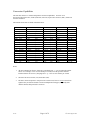
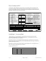
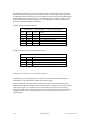
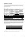
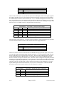
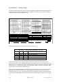
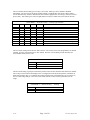
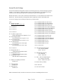
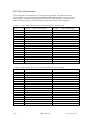
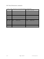
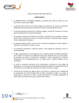
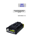
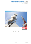
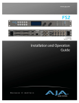
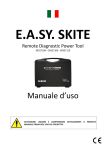
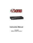
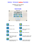
Model HD-8021 Up/Down and Cross Format Converter HD/SD-SDI Dual-Rate INPUT Model HD8021 HD/SD-SDI Dual-Rate OUTPUT HD/SD-SDI UP/DOWN/CROSS CONVERTER HD/SD-SDI Dual-Rate OUTPUT DIGITAL INPUTS HD SMPTE-292 or SD 259M-C Auto-Switching 8021 FEATURES ANALOG OUTPUTS HD: YPbPr, RGB and XGA SD: Composite, Component and Y/C HD/SD-SDI Dual-Rate OUTPUT DIGITAL OUTPUTS 2) Dual-Rate HD/SD-SDI Reclocked input copies 2) Dual-Rate HD/SD-SDI UP/DOWN or CROSS Converted HD/SD-SDI Dual-Rate OUTPUT POWER 5 VDC 1.8A or 6-18 VDC 9W User Adjustable Aspect Ratio and Overlay Reticules 3:2 Pull-down Insertion and i > p and p > i Conversion 1080i/p to/from 720p conversion Cobalt Digital Inc. G 5 12V Voice 217.344.1243 Fax 217.344.1245 www .cobaltdigital.com Owner’s Manual HD/SD Analog YPbPr RGB XGA OUTPUT SD - Analog Composite Y/G SD - Analog Composite Pb / B / Y SD - Analog Composite Pr / R / C Control RS-232 RS-485 Table of Contents: Overview ............................................................................................................................. 3 Block Diagram .................................................................................................................... 4 Signal Flow ......................................................................................................................... 4 Conversion Capabilities ...................................................................................................... 6 How to Configure an 8021 .................................................................................................. 7 Switch Bank 1 - Conversion Mode.................................................................................. 7 Detailed 8021 Switch Configuration Guide ................................................................. 9 Switch Bank 2 - Aspect Mode ....................................................................................... 10 Switch Bank 3 – Analog Output .................................................................................... 12 Switch Bank 4 – Reticule Overlay................................................................................. 15 Internal Switch Settings ................................................................................................. 17 8021 Delay Characteristics................................................................................................ 18 Glossary............................................................................................................................. 20 Specifications .................................................................................................................... 21 0.11a Page 2 of 21 Cobalt Digital 2004 Overview The HD-8021 is a high quality 10-bit, Down and Cross Format converter with monitoring grade up-conversion, that bridges SMPTE 292 high definition (HD) and 259M-C standard definition (SD) signal formats. The 8021 can Upconvert SD, Downconvert HD and Format convert from one HD standard into another and output HD/SD serial digital, HD analog and SD analog video. In addition, the 8021 can re-aspect the image, change i to p, p to i and add 3:2 pull-down. Safe Area reticules, 4x3 and 16x9, full aperture for 4x3 and center cross can be selected on any or all outputs. The image processing is full 10-bit using a 24-tap spatial filter. Down conversions of HD to SD signals are de-jittered to reduce chroma phase jitter of SD analog signals. All analog outputs are encoded at 12-bits to preserve the 10-bit video signal. HD/SD-SDI Dual-Rate INPUT Model HD8021 HD/SD-SDI Dual-Rate OUTPUT HD/SD-SDI UP/DOWN/CROSS CONVERTER HD/SD-SDI Dual-Rate OUTPUT DIGITAL INPUTS HD SMPTE-292 or SD 259M-C Auto-Switching 8021 FEATURES ANALOG OUTPUTS HD: YPbPr, RGB and XGA SD: Composite, Component and Y/C HD/SD-SDI Dual-Rate OUTPUT DIGITAL OUTPUTS 2) Dual-Rate HD/SD-SDI Reclocked input copies 2) Dual-Rate HD/SD-SDI UP/DOWN or CROSS Converted HD/SD-SDI Dual-Rate OUTPUT POWER 5 VDC 1.8A or 6-18 VDC 9W User Adjustable Aspect Ratio and Overlay Reticules 3:2 Pull-down Insertion and i > p and p > i Conversion 1080i/p to/from 720p conversion Cobalt Digital Inc. G 5 12V Voice 217.344.1243 Fax 217.344.1245 www .cobaltdigital.com HD/SD Analog YPbPr RGB XGA OUTPUT SD - Analog Composite Y/G SD - Analog Composite Pb / B / Y SD - Analog Composite Pr / R / C Control RS-232 RS-485 The input and outputs of the 8021 are the following. One dual-rate HD/SD serial digital input, with a set of reclocked dual-rate serial outputs and a set of imaged processed dual-rate digital outputs. Two sets of analog outputs, the first set is on HD-15 (XGA) connector and can be dualrate analog HD or SD analog. The second analog output is SD only and is supplied through three BNCs. All analog video outputs are encoded to 12-bits. The HD analog video can be YPbPr or GBR with either embedded tri-level or bi-level signals or H & V sync. The SD analog outputs on the BNC connectors, can be User configured as three composite, or one composite and one Y/C, or component in YPbPr (BetaCam, MII or SMPTE levels) or GBR with embedded sync. The SD output on the HD-15 (XGA) connector, in dual-rate analog mode can be either RGB or YPbPr in BetaCam, MII or SMPTE levels with embedded bi-level sync. 0.11a Page 3 of 21 Cobalt Digital 2004 Block Diagram The 8021 has a very flexible signal flow path and feature set that combines several products into one compact package. To understand the capabilities of the 8021, this section reviews the basic structure of the 8021. HD/SD Input Reclocked HD/SD Output Dual Rate Input Eq. Dual Rate Reclock, Decode and De-serialize Dual Rate Driver RS-485 RS-232 Serial I/O Down/Up & Format Conversion HD/SD Encoder Path Routing Sync Gen and Reticule Overlay Pb/B Pr/R Y/G/Cmpst SD-Analog Output HD/SD Dual Rate Serializer microprocessor Y/G HD/SD Analog Output Analog HD/SD Output Pb/B/Y Pr/R/C Dual Rate Driver HDSDI or SDI Output HD8021 Block Diagram Signal Flow Starting in the upper left of the block diagram, the dual-rate (HD/SD) serial digital signal is equalized, reclocked and then deserialized. During this process, the video standard and frame rate is determined. A copy of the reclocked digital serial is sent to a distribution amplifier to create two active and reclocked output loops. Each output is dual-rate and follows the input signal. Coming out of the deserializer, the parallel video data path goes in two directions. The first is to the conversion engine where it is up, down, format, aspect and/or frame rate converted depending on the signal input and User settings. The second copy of the deserializer goes is to an FPGA who’s function is to select which input goes to which output (digital, HD/SD analog) and what overlays are to be applied to individual outputs. Based on the Users setting of the external configuration dip switches and the type of signal detected at the deserializer, the hardware is automatically configured and the signal processing is sent to the correct output device to the right of the routing chip. Either, the converted signal or the raw signal is sent to the following: HD Digital to analog encoder (HD D/A), SD digital to analog encoder (SD D/A) or dual-rate serializer with or without reticule overlays on any of these paths as preset by the User. For example, this will allow the User to feed a HD monitor and have SD automatically be converted to HD for that monitor and with the aspect ratio and overlay pattern desired. When an HD signal is present, the preset conditions are set to bypass any conversions and thus the input HD signal is sent to the monitor. 0.11a Page 4 of 21 Cobalt Digital 2004 This works well if the monitor is 16x9 as HD input signals are likely to be in 16x9 format, but what if is an HD 4 x 3 monitor? In this case, the 8021 is configured such that the SD signal is in correct aspect, but not the HD. When the SD is sent to the scalar engine, it will be upconverted and kept in 4x3 aspect space. And the HD inputs would also go through the scalar engine, and be aspect changed to letterbox or center cut, depending on the User desired mode. For a SD output example, you’d have SD signals configured to bypass processing and HD signals downconverted and set to 4x3 aspect ratios. If your monitor were 16x9, the as above, you’d ARC the SD signal to 16x9 space (0.75H) and downconvert HD to SD without aspect correction. Outputting to an XGA monitor works the same way, but in this case a 4x3 XGA monitor would have SD being upconverted and HD being downconverted with aspect change. For a 16x9 XGA monitor, the SD would be upconverted and aspect changed while the HD would be downconverted. Should an alternate aspect ratio display be used, for example a 16x10 flat panel, set the user’s aspect settings (internal rotary switches) to adjust for the correct aspect ratio for both HD and SD signals. The user settings can be saved for recall should the 8021 be powered down. 0.11a Page 5 of 21 Cobalt Digital 2004 Conversion Capabilities The 8021 has extensive re-format and up/down conversion capabilities. It can act as an upconverted, downconverter, format (1080-720) converter, aspect ratio converter (ARC), frame rate converter and DVE. The Format conversions are listed in the chart below. From 1080 1080 1080 1080 1080 1080 1080 1080 1080 1080 720 720 720 720 720 720 486 575 To sF 23.98 p 23.98 sF 24 p 24 i 25 p 25 i 29.97 p 29.97 i 30 p 30 p 25 p 29.97 p 30 p 50 p 59.94 p 60 i 29.97 i 25 HD 1080 i 29.97 i 29.97 i 30 i 30 i 25 i 25 i 29.97 i 29.97 i 30 i 30 i 25 i 29.97 i 30 i 25 i 29.97 i 30 i 29.97 i 25 sF/p 23.98 p/sF 23.98 p 24 sF 24 p 25 p 25 p 29.97 p 29.97 p 30 p 30 p 25 p 29.97 p 30 p 50 p 29.97 p 30 p 29.97 p 25 HD 720 ---- p 59.94 XGA 1024x768 p 59.94 ---- p 59.94 p 59.94 ------p 25 p 25 p 29.97 p 29.97 p 30 p 30 p 25 p 29.97 p 30 p 25 p 29.97 p 30 p 29.97 p 25 p 60 p 60 p 50 p 50 p 59.94 p 59.94 p 60 p 60 p 50 p 59.94 p 60 p 50 p 59.94 p 60 p 59.94 p50 p 60 p 60 p 50 p 50 p 59.94 p 59.94 p 60 p 60 p 50 p 59.94 p 60 p 50 p 59.94 p 60 p 59.94 p 50 SD 486 i 29.97 486 i 29.97 ------575 i 25 575 i 25 486 i 29.97 486 i 29.97 ------575 i 25 486 i 29.97 ---575 i 25 486 i 29.97 ---486 i 29.97 575 i 25 Notes: 1. All rates translated to effective frame rates, interlaced rates “ i ” are two times the number shown. For example, i 29.97 is 59.94 fields per second (two fields per frame thus the interlaced frame rate is 29.97); but progressive “ p ” 29.97 is 29.97 frames per second. 2. SD active line rates are PAL (575) and NTSC (486). 3. The 8021 cannot accept native 720 p24/23.98 or sF24/23.98, however it can convert those signals if they are delivered inside a 59.94/60 transportation wrapper (as typically done with this format) and processed as 59.94/60. 0.11a Page 6 of 21 Cobalt Digital 2004 How to Configure an 8021 At first glance, understanding how to setup an 8021 can be daunting, but it does break down into four basic switch groups. The first bank (S1) sets the conversion mode, the second bank (S2), sets the aspect ratio and digital output rules, the third bank (S3) sets the analog encoder for both SD and HD and the fourth bank (S4) sets the overlay reticules. 8021 Switch Settings: The 8021 auto-detects the input standard and applies the conversion according to the user settings below. Aspect Control Switch 2 Conversion Mode Switch 1 1 2 ON OFF OFF ON OFF OFF ON ON 3 5 4 ON OFF OFF OFF ON OFF OFF OFF OFF ON OFF ON OFF ON ON ON ON ON 7 6 OFF OFF OFF ON ON OFF ON ON 8 9 10 IF SD Input then: SD Upconvert to 720 SD Upconvert to 1080 SD Re-aspect to SD Force to Analog XGA 1024x768 IF HD Input then: HD Downconvert HD Cross-Convert (1080 <> 720) HD Re-aspect to HD Force 720 p59.94/60/50 Force 1080 i 29.97/30/25 Output Analog XGA 1024x768 Video vs. Special Film Modes Video conversions (see below) Film i to p (e.g. 24sF to 24p) Film p to i (e.g. 24p to 24sF) Film p to i add 3:2 (24p/sF to 30i) Reserved Reserved Reserved Conversion Mode Examples: S1 NTSC to 1080i 29.97 NTSC to 720p 59.94 1080i 29.97 to NTSC 720p 59.97 to NTSC 1080p/sF 29.97 to 720p 59.94 720p 59.94 to 1080i 29.97 1080p/sF 23.98 to NTSC X X 1080p/sF 23.98 to 1080i 29.97 2 3 4 5 ON X X X OFF X X X X ON OFF OFF X ON OFF OFF X OFF ON OFF X OFF ON OFF S1 1 2 3 4 5 6 7 8 9 10 SD Input to SD/HD/XGA No Aspect change 0.75 Vert (Letter Box) 1.33 Vert 0.75 H (Pillar Box) 1.33 H (Center Cut) User Aspect Setting SD 10% Underscan HD Input to SD/HD/XGA No Aspect Change 0.75 Vert (Letter Box) 1.33 Ver 0.75 H (Pillar Box) 1.33 H (Center Cut) User Aspect Setting * HD 10% Underscan Digital Output Selection Analog Output Switch 3 Reticule (Overlay) Switch 4 2 3 1 ON ON ON ON OFF ON OFF ON ON OFF ON OFF OFFOFF ON OFF OFF OFF 4 5 6 7 8 ON OFF 1 2 3 Digital Out Follows Scalling Digital Out is always SD Digital Out is always HD Digital Out is copy of Input 6 OFF OFF OFF OFF OFF OFF X X ON OFF OFF OFF ON ON S2 1 2 3 4 5 6 7 8 9 10 Conversion Mode ON 0.10 1 OFF ON X X X X 1 2 3 ON ON ON OFF OFF ON OFF ON OFF ON OFF ON ON ON OFF OFF OFF OFF 4 5 7 6 ON ON ON OFF OFF ON OFF ON OFF ON OFF ON ON ON OFF OFF OFF OFF 8 9 10 OFF OFF ON OFF OFF ON ON ON 7 OFF OFF OFF OFF OFF OFF 9 ON OFF 10 ON OFF SD Analog configuration SD Composite 3 Copies SD Composite & Y/C SD YPbPr BetaCam ** SD YPbPr MII ** SD YPbPr SMPTE ** SD GBR ** SD Color ON/OFF SD Setup ON/OFF-NTSC SD Color Bars (Analog) Force SD to HD-Port * Oversample mode 2X on HD analog 16x on SD analog HD Analog Output HD Analog YPbPr ** HD Analog RGB ** HD Analog Sync Type Sync on Video - Tri-level H & V on External BNCs 4 5 6 7 8 9 10 4x3 Safe Area ON/OFF 4x3 Full Aperture ON/OFF 15x9 Safe Area ON/OFF User Reticle vs. Default ON/OFF Reticule Color WHT/ON-BLK/OFF Reticule Follows Zoom ON/OFF LED STATUS ON Locked and Operating No Power OFF Blink Slow No Input Signal Blink Fast Bad signal/mis-configuration * ** Dual Rate Analog - See Owner's Manual Only one component signal HD/SD at a time Video conversion chart for normal modes (S-1: 6-OFF; 7-OFF) 1080i<>720p i30 <> p60; i29.97 <> p59.94; 25i <> 50p 1080p<>720p 30p <> 30p; 29.97p <> 29.97p; 25p <> 25p All > XGA Auto > p60; p59.95, p50, p48(3:2 on 24/23.98) 1080 <> NTSC 23.98sF/p > i29.97; i/p29.97 > i29.97 720 <> NTSC p29.97 > i29.97; 59.94 > i29.97 OFF OFF OFF OFF Digital Out Reticules ON/OFF SD Analog Out Reticules ON/OFF HD Analog Out Reticules ON/OFF Center Cross ( + ) ON/OFF 1080 > PAL i25 > i25; p25 > i25 720 > PAL NTSC > 1080 p25 > i25; p50 > i25 NTSC > 720 PAL > 1080 PAL > 720 i29.97 > i29.97 i29.97 > p59.94 i25 > i25 i25 > p50 PAL settings are the same for PAL to PAL frame Rates Aspect Control Analog Output S3 1 2 3 4 5 6 7 8 9 10 Reticule (Overlay) S4 1 2 3 4 5 6 7 8 9 10 OFF Switch Bank 1 - Conversion Mode The first bank, S1 or Conversion Mode, is where the preset conversion rules are set for the obtaining the signal formats in the conversion capability chart. In the this group, the there are presets for SD inputs and presets for HD inputs. The first two switches (1-2) are for SD and determine what type of conversion to do when an SD signal is present. The next four switches (3-6) are for HD and determine what type of conversion to do when an HD signal is present. When SD is present, there are four types of SD conversion: SD upconvert to 720; SD upconvert to 1080; SD re-aspect to SD and SD to XGA (1024x768 The SD switch functions are: Switch Bank 1 – Conversion Mode - SD Conversion Settings S1-1 ON OFF OFF ON 0.11a S1-2 OFF ON OFF ON Function SD Upconvert to HD – 720 SD Upconvert to HD – 1080 SD Re-aspect to SD (DVE or ARC mode) SD Upconvert to XGA (analog 1024 x 768) Page 7 of 21 Cobalt Digital 2004 When HD is present, there are four types of HD conversions and four additional processing steps, such as interlaced to/from progressive and frame rate control. The four types of HD conversions are, HD Downconvert to SD, HD Cross-convert (Format Convert) 1080 to/from 720, HD Re-aspect to HD and HD to XGA (analog 1024x768). The additional controls for HD are: operate in video modes, convert interlaced signals to progressive, convert progressive to interlaced, and convert progressive to interlaced and add 3:2 pull down. The HD conversion switch functions are: Switch Bank 1 - Conversion Mode - HD Conversion Settings S1-3 S1-4 S1-5 Function ON OFF OFF ON OFF ON OFF ON OFF OFF ON ON OFF OFF OFF ON ON ON HD Downconvert to SD HD Crossconvert 1080 to/from 720 HD Re-aspect to HD (DVE or ARC) Force 720 p 60 / 59.94 / 50 Force 1080 i30 / i29.97 / i25 Force XGA (analog 1024 x 768) The HD extended conversion mode switch functions are: Switch Bank 1 - Conversion Mode – HD Extended Settings S1-6 OFF OFF ON ON S1-7 OFF ON OFF ON Function Normal HD conversion mode for Video applications Force interlace to progressive where possible Force progressive to interlace where possible Add 3:2 pull-down to 23.98/24 sF/p signals Switches S1-8, S1-9 and S1-10 are reserved for future use. A detailed listing of all input and output conversion modes with the corresponding settings for Switch Bank 1, is given the detailed settings chart on the next page. To use this chart, select the input on the left and go across until you find the match the desired output function at the top of the chart. If the conversion mode is supported, a letter will be present in the intersecting box. To configure the 8021 for this mode, look up the dip-switch settings associated with the “letter” at the bottom of the chart. In some cases, there is more than one way to configure the 8021 for the desired result and this is reflect by having more than on letter in the intersecting box. 0.11a Page 8 of 21 Cobalt Digital 2004 Detailed 8021 Switch Configuration Guide Serial Digital or Analog Output 1920 x 1080i i 30 i 30 i 29.97 H i 29.97 J 1920 x 1080 K K H,L K L D p 59.59 E D p 50 p 30 L H J H M,P A,C M,P A,C M J H K D A,B M,P L E D F M,N D,G E F D A,B M,P H D p 29.97 H K M,N D,G J A M J H K A M A M,N H M,N A,B p 25 F D K H M,N A,B 720x 625 1280 x720 p 60 K L p 23.98 J A i 25 Q R S T V U i 29.97 Q R S Switch Settings for Conversion Mode switch bank 1, switches 1-7 HD > SD HD<>HD 720<>1080 T V HD > HD (Re-aspect) HD > XGA SD > HD XX 101 00 D XX 011 00 H XX 001 00 M XX 111 00 Q 01 XXX 00 B XX 101 10 E XX 011 01 J XX 001 01 N XX 111 10 R 01 XXX 01 C XX 101 11 F XX 011 10 K XX 001 10 P XX 111 11 S 10 XXX 00 G XX 011 11 L XX 001 11 T 10 XXX 01 Page 9 of 21 U Note: 1 = ON 0 = Off X = doesn't matter A 0.11a i 29.97 M,N D F K M M D H i 25 M E F p 50 720x 525 Serial Digital Input p 24 F H p 60 p 59.95 E D H H,L sF 23.98 1024 x 768 Analog only 720x625 720x525 E D J K p 25 sF 24 D J H p 29.97 1280x720 p 30 p 29.97 p 25 sF 24 sF 23.98 p 24 p 23.98 p 60 p 59.59 p 50 p 30 p 29.97 p 25 H i 25 p 30 i 25 Cobalt Digital 2004 SD > SD U 00 XXX 00 SD > XGA V 11 XXX 00 Switch Bank 2 - Aspect Mode This bank controls the aspect mode for SD and HD inputs and the SDI output configuration. The first four switches determine the SD aspect rules for SD inputs and the second four switches determine the aspect rules for HD inputs. This enables preset rules that are unique for SD vs. HD signals as rule that will be applied automatically by the 8021. 8021 Switch Settings: The 8021 auto-detects the input standard and applies the conversion according to the user settings below. Aspect Control Switch 2 Conversion Mode Switch 1 1 2 ON OFF OFF ON OFF OFF ON ON 3 5 4 ON OFF OFF OFF ON OFF OFF OFF OFF ON OFF ON OFF ON ON ON ON ON 7 6 OFF OFF OFF ON ON OFF ON ON 8 9 10 Video vs. Special Film Modes Video conversions (see below) Film i to p (e.g. 24sF to 24p) Film p to i (e.g. 24p to 24sF) Film p to i add 3:2 (24p/sF to 30i) Reserved Reserved Reserved Conversion Mode Examples: NTSC to 1080i 29.97 NTSC to 720p 59.94 1080i 29.97 to NTSC 720p 59.97 to NTSC 1080p/sF 29.97 to 720p 59.94 720p 59.94 to 1080i 29.97 1080p/sF 23.98 to NTSC 1080p/sF 23.98 to 1080i 29.97 S1 S1 4 X X Reticule (Overlay) Switch 4 2 1 3 ON ON ON ON OFF ON OFF ON ON OFF ON OFF OFFOFF ON OFF OFF OFF 1 2 3 Digital Out is always SD Digital Out is always HD Digital Out is copy of Input X X X X X X ON OFF OFF ON OFF OFF OFF ON OFF X X OFF OFF OFF OFF X X X X ON OFF OFF OFF ON ON OFF OFF OFF OFF S2 1 2 3 4 5 6 7 8 9 10 ON 5 X X Analog Output Switch 3 Digital Out Follows Scalling 2 ON OFF 1 2 3 4 5 6 7 8 9 10 3 X X SD Input to SD/HD/XGA No Aspect change 0.75 Vert (Letter Box) 1.33 Vert 0.75 H (Pillar Box) 1.33 H (Center Cut) User Aspect Setting SD 10% Underscan HD Input to SD/HD/XGA No Aspect Change 0.75 Vert (Letter Box) 1.33 Ver 0.75 H (Pillar Box) 1.33 H (Center Cut) User Aspect Setting * HD 10% Underscan Digital Output Selection 1 OFF ON Conversion Mode ON 0.10 1 2 3 ON ON ON OFF OFF ON OFF ON OFF ON OFF ON ON ON OFF OFF OFF OFF 4 5 7 6 ON ON ON OFF OFF ON OFF ON OFF ON OFF ON ON ON OFF OFF OFF OFF 8 9 10 OFF OFF ON OFF OFF ON ON ON IF SD Input then: SD Upconvert to 720 SD Upconvert to 1080 SD Re-aspect to SD Force to Analog XGA 1024x768 IF HD Input then: HD Downconvert HD Cross-Convert (1080 <> 720) HD Re-aspect to HD Force 720 p59.94/60/50 Force 1080 i 29.97/30/25 Output Analog XGA 1024x768 6 7 OFF OFF OFF OFF OFF OFF OFF OFF OFF OFF Aspect Control 4 5 6 7 8 ON OFF 9 ON OFF 10 ON OFF 4 5 6 7 8 9 Digital Out Reticules ON/OFF SD Analog Out Reticules ON/OFF HD Analog Out Reticules ON/OFF Center Cross ( + ) ON/OFF 4x3 Safe Area ON/OFF 4x3 Full Aperture ON/OFF 15x9 Safe Area ON/OFF User Reticle vs. Default ON/OFF Reticule Color WHT/ON-BLK/OFF 10 Reticule Follows Zoom ON/OFF LED STATUS ON Locked and Operating No Power OFF Blink Slow No Input Signal Blink Fast Bad signal/mis-configuration * ** Dual Rate Analog - See Owner's Manual Only one component signal HD/SD at a time Video conversion chart for normal modes (S-1: 6-OFF; 7-OFF) 1080i<>720p i30 <> p60; i29.97 <> p59.94; 25i <> 50p 1080p<>720p 30p <> 30p; 29.97p <> 29.97p; 25p <> 25p All > XGA Auto > p60; p59.95, p50, p48(3:2 on 24/23.98) 1080 <> NTSC 23.98sF/p > i29.97; i/p29.97 > i29.97 720 <> NTSC p29.97 > i29.97; 59.94 > i29.97 1080 > PAL i25 > i25; p25 > i25 720 > PAL NTSC > 1080 p25 > i25; p50 > i25 NTSC > 720 PAL > 1080 PAL > 720 i29.97 > i29.97 i29.97 > p59.94 i25 > i25 i25 > p50 PAL settings are the same for PAL to PAL frame Rates Analog Output S3 SD Analog configuration SD Composite 3 Copies SD Composite & Y/C SD YPbPr BetaCam ** SD YPbPr MII ** SD YPbPr SMPTE ** SD GBR ** SD Color ON/OFF SD Setup ON/OFF-NTSC SD Color Bars (Analog) Force SD to HD-Port * Oversample mode 2X on HD analog 16x on SD analog HD Analog Output HD Analog YPbPr ** HD Analog RGB ** HD Analog Sync Type Sync on Video - Tri-level H & V on External BNCs 1 2 3 4 5 6 7 8 9 10 Reticule (Overlay) S4 1 2 3 4 5 6 7 8 9 10 OFF The first four switches (S2 - 1,2,3,4) control the aspect ratio of SD inputs. When an SD signal is applied at the input, regardless of how it will be format converted in the output, the aspect rules for the SD input are controlled by first three switches (S2 – 1,2,3). If the SD is being upconverted to HD (16x9 space), then for correct aspect ratios, the User has to either Pillar box (reduce the H axis by multiplying by 0.75) otherwise the aspect ratio will be incorrect. Enabling User aspect mode allows the User to set ASPECT ratios by using the internal switch settings. Switch Bank 2 - Aspect Mode - SD Aspect Ratio Settings S2-1 ON OFF OFF ON ON OFF S2-2 ON OFF ON OFF ON OFF S2-3 ON ON OFF ON OFF OFF Function is applied to SD inputs only No aspect Change for SD inputs 0.75 V (letter box) – reduce Vertical to 75% 1.33 V – expand Vertical by 133% 0.75 H (pillar box) – reduce Horiz. to 75% 1.33 H (center cut) – expand Horiz. by 133% User Aspect settings (set via internal switches) The fourth switch (S2 – 4) controls electronic underscan. When enabled, the 8021 provides a convenient underscan mode which is useful on CRT monitors that do have underscan controls. 0.11a Page 10 of 21 Cobalt Digital 2004 Switch Bank 2 - Aspect Mode - SD Underscan Control S2-4 Function ON Reduce image by an additional 10 percent OFF No aspect reduction The next four switches (S2 – 5,6,7,8) control the aspect ratio of HD inputs. When an HD signal is applied at the input, regardless of how it will be format converted in the output, the aspect rules for the HD input are controlled by the first three of these switches (S2 - 5,6,7). If the HD is being downconverted to a 4x3 space, the to be aspect correct the User has to either Letter box (reduce the vertical axis to 0.75) or Center cut, by expand the H axis by 1.333 otherwise the aspect ratio will be incorrect. Enabling User aspect mode allows the User to set ASPECT ratios by using the internal switch settings. Switch Bank 2 - Aspect Mode - HD Aspect Ratio settings S2-6 S2-7 Function is applied to HD inputs only ON ON No aspect change OFF ON 0.75 V (letter box) – reduce Vertical to 75% ON OFF 1.33 V – expand Vertical by 133% OFF ON 0.75 H (pillar box) – reduce Horiz. to 75% ON OFF 1.33 H (center cut) – expand Horiz. by 133% OFF OFF User Aspect settings (set via internal switches) S2-5 ON OFF OFF ON ON OFF The fourth switch of this group (S2 – 8) controls electronic underscan. When enabled, the 8021 provides a convenient underscan which is useful on CRT monitors that do not support underscans. Switch Bank 2 - Aspect Mode - HD Underscan Control S2-8 ON OFF Function Reduce image by an additional 10 percent No aspect reduction The last two switches of bank 2 control the Dual-rate HD/SD SDI image processed outputs. They can be set to track the output of the scaling engine, which is setup by S1 (1-7), forced to always be SD, forced to always be HD and set to be reclocked copies of the input. The forced SD or HD functions are use full if you are driving an SD only or HD only source. For example if you are using a SD Digital Waveform monitor to monitor the output of a dual rate router. The 8021 could be configured to output only SD on the imaged processed HD/SD SDI output BNCs. If the source selected on the router were SD, then the signal would bypass image scaling and go directly to the output BNCs. On the other hand if and HD source were called up on the router, the HD signal would be downconverted and sent to the output BNCs. This does require that the input conversion mode switches, S1 (3,4,5) be set to downconvert. Otherwise the HD downconversion does not take place and the “force SD” outputs we be muted. Switch Bank 2 – Aspect Mode - HD/SD-SDI Output Configuration S2-9 OFF OFF ON ON 0.11a S2-10 OFF ON OFF ON Function Digital OUT Follows Scaling Digital OUT is Forced SD Digital OUT is Forced HD Digital OUT is a copy of Digital Input Page 11 of 21 Cobalt Digital 2004 Switch Bank 3 – Analog Output The third switch bank controls the analog encoder’s configuration. Both the HD and SD analog outputs are configured by these switches. Additional analog configuration is available using the interior switches as described in the Internal Switch Setting section. 8021 Switch Settings: The 8021 auto-detects the input standard and applies the conversion according to the user settings below. Aspect Control Switch 2 Conversion Mode Switch 1 1 2 ON OFF ON OFF OFF OFF ON ON 3 5 4 ON OFF OFF OFF ON OFF OFF OFF OFF ON OFF ON OFF ON ON ON ON ON 7 6 OFF OFF OFF ON ON OFF ON ON 8 9 10 Video vs. Special Film Modes Video conversions (see below) Film i to p (e.g. 24sF to 24p) Film p to i (e.g. 24p to 24sF) Film p to i add 3:2 (24p/sF to 30i) Reserved Reserved Reserved Conversion Mode Examples: S1 NTSC to 1080i 29.97 NTSC to 720p 59.94 1080i 29.97 to NTSC 720p 59.97 to NTSC 1080p/sF 29.97 to 720p 59.94 720p 59.94 to 1080i 29.97 1080p/sF 23.98 to NTSC 1080p/sF 23.98 to 1080i 29.97 S1 4 X X Reticule (Overlay) Switch 4 2 1 3 ON ON ON ON OFF ON OFF ON ON OFF ON OFF OFFOFF ON OFF OFF OFF 1 2 3 Digital Out is always SD Digital Out is always HD Digital Out is copy of Input X X X X X X ON OFF OFF ON OFF OFF OFF ON OFF X X OFF OFF OFF OFF X X X X ON OFF OFF OFF ON ON OFF OFF OFF OFF S2 1 2 3 4 5 6 7 8 9 10 ON 5 X X Analog Output Switch 3 Digital Out Follows Scalling 2 ON OFF 1 2 3 4 5 6 7 8 9 10 3 X X SD Input to SD/HD/XGA No Aspect change 0.75 Vert (Letter Box) 1.33 Vert 0.75 H (Pillar Box) 1.33 H (Center Cut) User Aspect Setting SD 10% Underscan HD Input to SD/HD/XGA No Aspect Change 0.75 Vert (Letter Box) 1.33 Ver 0.75 H (Pillar Box) 1.33 H (Center Cut) User Aspect Setting * HD 10% Underscan Digital Output Selection 1 OFF ON Conversion Mode ON 0.10 1 2 3 ON ON ON OFF OFF ON OFF ON OFF ON OFF ON ON ON OFF OFF OFF OFF 4 5 7 6 ON ON ON OFF OFF ON OFF ON OFF ON OFF ON ON ON OFF OFF OFF OFF 8 9 10 OFF OFF ON OFF OFF ON ON ON IF SD Input then: SD Upconvert to 720 SD Upconvert to 1080 SD Re-aspect to SD Force to Analog XGA 1024x768 IF HD Input then: HD Downconvert HD Cross-Convert (1080 <> 720) HD Re-aspect to HD Force 720 p59.94/60/50 Force 1080 i 29.97/30/25 Output Analog XGA 1024x768 6 7 OFF OFF OFF OFF OFF OFF OFF OFF OFF OFF Aspect Control 4 5 6 7 8 ON OFF 9 ON OFF 10 ON OFF Digital Out Reticules ON/OFF SD Analog Out Reticules ON/OFF HD Analog Out Reticules ON/OFF Center Cross ( + ) ON/OFF 4 5 6 7 8 9 4x3 Safe Area ON/OFF 4x3 Full Aperture ON/OFF 15x9 Safe Area ON/OFF User Reticle vs. Default ON/OFF Reticule Color WHT/ON-BLK/OFF 10 Reticule Follows Zoom ON/OFF LED STATUS ON Locked and Operating No Power OFF Blink Slow No Input Signal Blink Fast Bad signal/mis-configuration * ** Dual Rate Analog - See Owner's Manual Only one component signal HD/SD at a time Video conversion chart for normal modes (S-1: 6-OFF; 7-OFF) 1080i<>720p i30 <> p60; i29.97 <> p59.94; 25i <> 50p 1080p<>720p 30p <> 30p; 29.97p <> 29.97p; 25p <> 25p All > XGA Auto > p60; p59.95, p50, p48(3:2 on 24/23.98) 1080 <> NTSC 23.98sF/p > i29.97; i/p29.97 > i29.97 720 <> NTSC p29.97 > i29.97; 59.94 > i29.97 1080 > PAL i25 > i25; p25 > i25 720 > PAL NTSC > 1080 p25 > i25; p50 > i25 NTSC > 720 PAL > 1080 PAL > 720 i29.97 > i29.97 i29.97 > p59.94 i25 > i25 i25 > p50 PAL settings are the same for PAL to PAL frame Rates Analog Output S3 SD Analog configuration SD Composite 3 Copies SD Composite & Y/C SD YPbPr BetaCam ** SD YPbPr MII ** SD YPbPr SMPTE ** SD GBR ** SD Color ON/OFF SD Setup ON/OFF-NTSC SD Color Bars (Analog) Force SD to HD-Port * Oversample mode 2X on HD analog 16x on SD analog HD Analog Output HD Analog YPbPr ** HD Analog RGB ** HD Analog Sync Type Sync on Video - Tri-level H & V on External BNCs 1 2 3 4 5 6 7 8 9 10 Reticule (Overlay) S4 1 2 3 4 5 6 7 8 9 10 OFF The SD analog output type is selected by the first three switches of S3. Switch Bank 3 - Analog Output Configuration – SD Setup S3-1 ON ON OFF OFF OFF S3-2 ON OFF ON ON OFF S3-3 ON ON ON OFF ON Function - SD Analog Configuration SD Composite – 3 copies SD Composite and Y/C SD YPbPr BetaCam(tm) levels ** SD YPbPr MII (tm) levels ** SD YPbPr SMPTE levels ** ** The HD/SD analog encoder can support dual composite and component operation but not dual component at the time. Thus, if both the analog HD15 port and BNC ports are used simultaneously, only one port can be set to component encoding. If SD component encoding is selected for the SD BNC outputs and the unit is not in dual-rate analog mode, then the HD outputs (HD-15 connector) are shut down until the SD output is reconfigured for Composite or Y/C. However in dual-rate analog mode for the HD15 connector, the SD BNCs are shut down and component HD and SD are available on the HD15 port. This is possible because only one format, HD or SD is available on this port at a time. The dual-rate analog mode is designed for dual-rate analog monitors that accept both HD and SD inputs on the same input connector. When in Dual-rate analog mode, only analog 0.11a Page 12 of 21 Cobalt Digital 2004 component and HD component outputs are allowed on the HD-15 connector. The types of component analog outputs are configured via Switch Bank 3. In dual-rate analog mode, HD signals can be set to H&V sync or tri-level (also bi-level by the internal configuration switches). The SD signals will have normal SD bi-level sync. Switch Bank 3 - Analog Output Configuration - SD Setup Continued S3-4 ON OFF Function Color / Monochrome Mode SD color ON SD color OFF – useful for driving B&W monitors Switch Bank 3 - Analog Output Configuration - SD Setup Continued S3-5 ON OFF Function Setup Control for NTSC SD Setup ON (NTSC signals only) SD Setup OFF Switch Bank 3 - Analog Output Configuration - SD Color Bars S3-6 ON OFF Function Color Bars SD Analog Color Bars ON SD Analog Color Bars OFF Switch Bank 3 - Analog Output Configuration - HD/SD control S3-7 ON OFF Function Dual-rate Analog Mode Force SD to HD port (HD15-XGA connector) Keep SD on SD BNCs The purpose of the analog dual-rate mode is to allow a single connection to a multi-rate broadcast monitor, rather than a two connections (HD & SD) that would force an end user to select a different monitor input as the input standard changes between HD and SD. In dual-rate analog mode, both HD and SD inputs are routed to the HD analog output connector (HD-15). Aspect ratio rules and overlays can be pre-configured and applied automatically. The first production runs of the 8021, Revision A boards, can be upgraded to the latest dual-rate firmware. However in dual-rate analog output mode and only in this mode, the color difference BNCs on the HD break out cable must be reversed. The HD15 red cable is used for Pb or B and the blue cable for Pr R signals. Revision B and higher boards do not require this flip for dual-rate analog output mode. Switch Bank 3 - Analog Output Configuration - HD/SD S3-8 Function Oversample Mode ON Oversample HD by 2x (SD by 4x) OFF Oversample SD by 16x (HD by 1x) 0.11a Page 13 of 21 Cobalt Digital 2004 The oversample mode is only for the analog output encoder. Oversampling increases video quality and can only be applied to one of the two output banks, HD and SD. In dual-rate analog mode, only one bank (the HD bank) is used and the highest sampling rate for SD/HD is automatically configured (16x for SD and 2x for HD). In non-dual rate analog mode, the end user can choose which analog output group will have higher signal processing. The last two analog output switches set up the HD color type (YPbPr or RGB) and sync type. Switch Bank 3 - Analog Output Configuration - HD Setup S3-9 ON OFF Function Color Type HD Component YPbPr HD Component RGB Switch Bank 3 - Analog Output Configuration - HD Setup S3-10 ON OFF Function HD Sync selection Embedded Tri-level H & V external Sync can be either embedded on the HD video as tri-level or bi-level or as external H&V. To select bilevel you must use the internal rotary switches and change the embedded sync type to bi-level. The default embedded sync is tri-level and is on all three output HD channels (YPbPr or RGB). If H&V external sync is selected, the embedded sync is removed for RGB signals and H&V are sent to the H&V connections on the HD-15 connector. 0.11a Page 14 of 21 Cobalt Digital 2004 Switch Bank 4 – Reticule Overlay The Fourth Bank of switches control the reticule overlays. This overlay engine is very flexible and can be enabled or disabled at any of the outputs (SDI, HD analog and SD analog) and can be user programmed with other aspect ratios via the internal rotary switches and saved in non-volatile memory. This allows the creation of film aspect ratios or video aspect ratios specific to the project at hand. 8021 Switch Settings: The 8021 auto-detects the input standard and applies the conversion according to the user settings below. Aspect Control Switch 2 Conversion Mode Switch 1 1 2 ON OFF OFF ON OFF OFF ON ON 3 5 4 ON OFF OFF OFF ON OFF OFF OFF OFF ON OFF ON OFF ON ON ON ON ON 7 6 OFF OFF OFF ON ON OFF ON ON 8 9 10 Video vs. Special Film Modes Video conversions (see below) Film i to p (e.g. 24sF to 24p) Film p to i (e.g. 24p to 24sF) Film p to i add 3:2 (24p/sF to 30i) Reserved Reserved Reserved Conversion Mode Examples: NTSC to 1080i 29.97 NTSC to 720p 59.94 1080i 29.97 to NTSC 720p 59.97 to NTSC 1080p/sF 29.97 to 720p 59.94 720p 59.94 to 1080i 29.97 1080p/sF 23.98 to NTSC 1080p/sF 23.98 to 1080i 29.97 S1 S1 4 X X Reticule (Overlay) Switch 4 2 1 3 ON ON ON ON OFF ON OFF ON ON OFF ON OFF OFFOFF ON OFF OFF OFF 1 2 3 Digital Out is always SD Digital Out is always HD Digital Out is copy of Input X X X X X X ON OFF OFF ON OFF OFF OFF ON OFF X X OFF OFF OFF OFF X X X X ON OFF OFF OFF ON ON OFF OFF OFF OFF S2 1 2 3 4 5 6 7 8 9 10 ON 5 X X Analog Output Switch 3 Digital Out Follows Scalling 2 ON OFF 1 2 3 4 5 6 7 8 9 10 3 X X SD Input to SD/HD/XGA No Aspect change 0.75 Vert (Letter Box) 1.33 Vert 0.75 H (Pillar Box) 1.33 H (Center Cut) User Aspect Setting SD 10% Underscan HD Input to SD/HD/XGA No Aspect Change 0.75 Vert (Letter Box) 1.33 Ver 0.75 H (Pillar Box) 1.33 H (Center Cut) User Aspect Setting * HD 10% Underscan Digital Output Selection 1 OFF ON Conversion Mode ON 0.10 1 2 3 ON ON ON OFF OFF ON OFF ON OFF ON OFF ON ON ON OFF OFF OFF OFF 4 5 7 6 ON ON ON OFF OFF ON OFF ON OFF ON OFF ON ON ON OFF OFF OFF OFF 8 9 10 OFF OFF ON OFF OFF ON ON ON IF SD Input then: SD Upconvert to 720 SD Upconvert to 1080 SD Re-aspect to SD Force to Analog XGA 1024x768 IF HD Input then: HD Downconvert HD Cross-Convert (1080 <> 720) HD Re-aspect to HD Force 720 p59.94/60/50 Force 1080 i 29.97/30/25 Output Analog XGA 1024x768 6 7 OFF OFF OFF OFF OFF OFF OFF OFF OFF OFF Aspect Control 4 5 6 7 8 ON OFF 9 ON OFF 10 ON OFF 4 5 6 7 8 9 Digital Out Reticules ON/OFF SD Analog Out Reticules ON/OFF HD Analog Out Reticules ON/OFF Center Cross ( + ) ON/OFF 4x3 Safe Area ON/OFF 4x3 Full Aperture ON/OFF 15x9 Safe Area ON/OFF User Reticle vs. Default ON/OFF Reticule Color WHT/ON-BLK/OFF 10 Reticule Follows Zoom ON/OFF LED STATUS ON Locked and Operating No Power OFF Blink Slow No Input Signal Blink Fast Bad signal/mis-configuration * ** Dual Rate Analog - See Owner's Manual Only one component signal HD/SD at a time Video conversion chart for normal modes (S-1: 6-OFF; 7-OFF) 1080i<>720p i30 <> p60; i29.97 <> p59.94; 25i <> 50p 1080p<>720p 30p <> 30p; 29.97p <> 29.97p; 25p <> 25p All > XGA Auto > p60; p59.95, p50, p48(3:2 on 24/23.98) 1080 <> NTSC 23.98sF/p > i29.97; i/p29.97 > i29.97 720 <> NTSC p29.97 > i29.97; 59.94 > i29.97 1080 > PAL i25 > i25; p25 > i25 720 > PAL NTSC > 1080 p25 > i25; p50 > i25 NTSC > 720 PAL > 1080 PAL > 720 i29.97 > i29.97 i29.97 > p59.94 i25 > i25 i25 > p50 PAL settings are the same for PAL to PAL frame Rates Analog Output S3 SD Analog configuration SD Composite 3 Copies SD Composite & Y/C SD YPbPr BetaCam ** SD YPbPr MII ** SD YPbPr SMPTE ** SD GBR ** SD Color ON/OFF SD Setup ON/OFF-NTSC SD Color Bars (Analog) Force SD to HD-Port * Oversample mode 2X on HD analog 16x on SD analog HD Analog Output HD Analog YPbPr ** HD Analog RGB ** HD Analog Sync Type Sync on Video - Tri-level H & V on External BNCs 1 2 3 4 5 6 7 8 9 10 Reticule (Overlay) S4 1 2 3 4 5 6 7 8 9 10 OFF The overlay engine can be enable or disable for each type of 8021 output; HD/SD-SDI, HD Analog and SD Analog. This can allow a clean vs. dirty overlay feed. For example the 8021 can be used to create a digital to digital downconvert while outputting analog HD and analog SD with user overlays. Each output type can be enabled or disable separately as shown in the table below. Switch Bank 4 – Reticule Overlay - Output Enable S4-1 ON OFF S4-2 S4-3 ON OFF ON OFF 0.11a Function Enable overlays on dual-rate HD/SD SDI output Disable overlays on dual-rate HD/SD SDI output Enable overlays on analog SD output Disable overlays on analog SD output Enable overlays on analog HD output Disable overlays on analog HD output Page 15 of 21 Cobalt Digital 2004 The next switches define what type of overlay is to be used. Each type can be enabled or disabled individually. The user can use the factory default settings or program their own and save those settings. Use the internal rotary switches, defined in the next section to program the user settings. Place S4-8 to user presets (ON). This feature gives a total of eight different overlays of which four can be used at one time. Switch Bank 4 – Reticule Overlay - Overlay Type Selection S4-4 ON OFF S4-5 S4-6 S4-7 S4-8 ON OFF ON OFF ON OFF ON OFF Function Center Cross Enable or User Preset Center Cross Disable or User Preset 4 x 3 Safe Area Enable or User Preset 4 x 3 Safe Area Disable or User Preset 4 x 3 Full Aperture Enable or User Preset 4 x 3 Full Aperture Disable or User Preset 16 x 9 Safe Area Enable or User Preset 16 x 9 Safe Area Disable or User Preset User Presets Enabled (internal switches to configure) Factory Defaults Enabled The next switch setting selects black or white reticules. The overlay can be User programmed, via internal switches, to be any color and saved as a user default. This user color would be present when the User Preset Enable switch (S4-8) is ON. Switch Bank 4 – Reticule Overlay - Color Selection S4-9 ON OFF Function Reticule color is White or User Preset Reticule color is Black or User Preset The last switch setting of group for controls the position of the reticules when the DVE function is enabled. The overlays can be locked to the display raster or configured to track the DVE expansion, contraction or PAN along with the video. For example, the tracking reticule mode would enable the User to zoom in on one size of the image and get a close view of the video with the overlay correctly positioned over the image. Switch Bank 4 – Reticule Overlay - Tracking S4-10 ON OFF 0.11a Function Reticule tracks the DVE or ARC control Reticule is locked to picture raster Page 16 of 21 Cobalt Digital 2004 Internal Switch Settings The 8021 has additional configuration controls via internal register rotary selection and input (up/down) switches. To access these controls, disconnect power, remove the bottom cover and locate two rotary switches (S5, S6) and two push button (S7-UP, S8-Down) switches and reapply power. Default convention: Use S7 (UP) to increment or turn function on. Use S8 (Down) to decrement or turn function off. On most functions, pressing both S7 & S8 (Up & Down) restores the default mode. To save user settings, select 99 and press either the Up or Down switch. 60: User Reticule Mode Vert bars size H 61: User Reticule Mode Vert bars thickness 62: User Reticule Mode 4x3 box Horz size 63: User Reticule Mode 4x3 box Vert size 64: User Reticule Mode 4x3 box Horz Thickness 65: User Reticule Mode 4x3 box Vert Thickness 66: User Reticule Mode 16x9 box Horz size 67: User Reticule Mode 16x9 box Vert size 68: User Reticule Mode 16x9 box Horz Thickness 69: User Reticule Mode 16x9 box Vert Thickness S5S6 00: Normal User Mode Restore to 00 prior to device use 10-19: Reserved 20-29: Reserved 30-39: Reserved 40: User H & V aspect zoom Press both buttons to set aspect to 1 to 1 41: User H aspect zoom Press both buttons to set aspect to 1 to 1 42: User V aspect zoom Press both buttons to set aspect to 1 to 1 43: User H aspect pan Press both buttons to center H-pan 44: User V aspect pan Press both buttons to center V-pan 50-53: Reserved 54: Background color Y Push both buttons default to black 55: Background Cb color Push both buttons default to black 56: Background Cr color Push both buttons default to black 57: Enable over sampling on Encoder Default is on 70: User Reticule Mode Cross Horz size 71: User Reticule Mode Cross Vert size 72: User Reticule Mode Cross Horz Thickness 73: User Reticule Mode Cross Vert Thickness 74: User Reticule Mode Y Level 75: User Reticule Mode Cb Level 76: User Reticule Mode Cr Level 74-83, 86: Reserved 84: HD Analog Embedded SYNC UP = tri-level (default) Down = bi-level 85: SD-SDI/Analog Dejitter UP = Filter ON Down = Filter OFF 87: HD < > SD Color Matrix Bypass UP = Bypass color matrix Down = enable color matrix 88: Restore factory defaults 58: Enable HD VBI Default is on 59: Enable SD VB Default is on 89-98: Reserved 99: Save current values Make certain that the rotary switches are restored to 0, 0 before re-installing the bottom cover. 0.11a Page 17 of 21 Cobalt Digital 2004 8021 Delay Characteristics The processing delay varies with the type of conversion being performed. The charts below list the electrical length or processing time for the HD/SD-SDI and Analog HD/SD outputs. The first chart is for 1080 outputs, the second for 720 and the third for XGA and SD. Select the input rate on the left and the output rate and type on the top. The intersecting box contains the conversion time information. f = field; F = Frame – Delay rates (in f or F) are shown with respect to the input signal. From 1080 1080 1080 1080 1080 1080 1080 1080 1080 1080 720 720 720 720 720 720 486 575 To sF 23.98 p 23.98 sF 24 p 24 i 25 p 25 i 29.97 p 29.97 i 30 p 30 p 25 p 29.97 p 30 p 50 p 59.94 p 60 i 29.97 i 25 HD 1080 (SDI or Analog Output) HD 1080 (SDI or Analog Output) i 29.97 i 29.97 i 30 i 30 i 25 i 25 i 29.97 i 29.97 i 30 i 30 i 25 i 29.97 i 30 i 25 i 29.97 i 30 i 29.97 i 25 1/13.32-1/11.99 sec – 3.6-4f 1/13.32-1/11.99 sec – 1.8-2F 3/40-1/12 sec – 3.6-4f 3/40-1/12 sec – 1.8-2F 1/25 sec – 2f 1/12.5 sec – 2F 1/30 sec – 2f 1/15 sec – 2F 1/30 sec – 2f 1/15 sec – 2F 1/12.5 sec – 2F 1/14.98 sec – 2F 1/15 sec – 2F 1/25 sec – 2F 1/29.97 – 2F 1/30 sec – 2F 1/29.97 – 2f 1/25 – 2f sF/p 23.98 p/sF 23.98 p 24 sF 24 p 25 p 25 p 29.97 p 29.97 p 30 p 30 p 25 p 29.97 p 30 p 50 p 29.97 p 30 p 29.97 p 25 1/11.99 sec – 4f 1/11.99 sec – 2F 1/12 sec – 4f 1/12 sec – 2F 1/12.5 sec – 2f 1/12.5 sec – 2F 1/14.98 sec – 2f 1/14.98 sec – 2F) 1/15 sec – 4f 1/15 sec – 2F 1/12.5 sec – 2F 1/14.98 sec – 2F 1/15 sec – 2F 1/50 sec – 1F 1/14.98 – 4F 1/15 – 4F 1/14.98 – 4f 1/25 – 4f f = field; F = Frame – Delay rates (in f or F) are shown with respect to the input signal. From 1080 1080 1080 1080 1080 1080 1080 1080 1080 1080 720 720 720 720 720 720 486 575 0.11a To HD 720 sF 23.98 p 23.98 sF 24 p 24 i 25 p 25 i 29.97 p 29.97 i 30 p 30 p 25 p 29.97 p 30 p 50 p 59.94 p 60 i 29.97 i 25 ------------p 25 p 25 p 29.97 p 29.97 p 30 p 30 p 25 p 29.97 p 30 p 25 p 29.97 p 30 p 29.97 p 25 (SDI or Analog Output) 1/25 sec – 4f 1/12.5 sec – 2F 1/29.97 sec – 4f 1/14.98 sec – 2F 1/15 sec – 4f 1/15 sec – 2F 1/12.5 sec – 2F 1/14.98 sec – 2F 1/15 sec – 2F 1/12.5 sec – 4F 1/14.98 sec – 4F 1/15 sec – 4F 1/14.98 sec – 4f 1/12.5 sec – 4f Page 18 of 21 HD 720 (SDI or Analog Output) p 59.94 p 59.94 p 60 p 60 p 50 p 50 p 59.94 p 59.94 p 60 p 60 p 50 p 59.94 p 60 p 50 p 59.94 p 60 p 59.94 p50 1/13.32-1/11.99 sec – 3.6-4f 1/13.32-1/11.99 sec – 1.8-2F 3/40-1/12 sec – 3.6-4f 3/40-1/12 sec – 1.8-2F 1/25 sec – 2f 1/12.5 sec – 2F 1/29.97 sec – 2f 1/14.98 sec – 2F 1/15 sec – 4f 1/15 sec – 2F 1/12.5 sec – 2F 1/14.98 sec – 2F 1/15 sec – 2F 1/50 sec – 2F 1/29.97 sec – 2F 1/30 sec – 2F 1/29.97 sec – 2f 1/25 sec – 2f Cobalt Digital 2004 8021 Delay Characteristics (continued) f = field; F = Frame – Delay rates (in f or F) are shown with respect to the input signal. SD-SDI or SD-Analog Output From To XGA 1024x768 (Analog output) 486 = NTSC & 575 = PAL 1080 sF 23.98 p 59.94 1/13.32-1/11.99 sec – 3.6-4f 486 i 29.97 1/13.32-1/11.99 sec – 3.6-4f 1080 p 23.98 p 59.94 1/13.32-1/11.99 sec – 1.8-2F 486 i 29.97 1/13.32-1/11.99 sec – 1.8-2F 1080 sF 24 p 60 3/40-1/12 sec – 3.6-4f ---1080 p 24 p 60 3/40-1/12 sec – 1.8-2F ---1080 i 25 p 50 1/25 sec – 2f 575 i 25 1/25 sec – 2f 1080 p 25 p 50 1/12.5 sec – 2F 575 i 25 1/12.5 sec – 2F 1080 i 29.97 p 59.94 1/29.97 sec – 2f 486 i 29.97 1/29.97 sec – 2f 1080 p 29.97 p 59.94 1/14.98 sec – 2F 486 i 29.97 1/14.98 sec – 2F 1080 i 30 p 60 1/15 sec – 4f ---1080 p 30 p 60 1/15 sec – 2F ---720 p 25 p 50 1/12.5 sec – 2F 575 i 25 1/12.5 sec – 2F 720 p 29.97 p 59.94 1/14.98 sec – 2F 486 i 29.97 1/14.98 sec – 2F 720 p 30 p 60 1/15 sec – 2F ---720 p 50 p 50 1/50 sec – 2F 575 i 25 1/25 sec – 2F 720 p 59.94 p 59.94 1/29.97 sec – 2F 486 i 29.97 1/29.97 sec – 2F 720 p 60 p 60 1/30 sec – 2F ---486 i 29.97 p 59.94 1/29.97 sec – 2f 486 i 29.97 1/29.97 sec – 2f 575 i 25 p50 1/25 sec – 2f 575 i 25 1/25 sec – 2f 0.11a Page 19 of 21 Cobalt Digital 2004 Glossary Aspect ratio: Performing an aspect change on HD or SD raster, for example converting the image from 16x9 to 4x3 with letter box (0.75V) or non-letter box by expanding H by 1.333. Downconvert: Taking HD and down converting it to SD or XGA. Format convert: Taking HD from one resolution and crossing converting it over to another HD standard, for example (1080 to 720) or (720 to 1080). Sometimes this is referred to as crossconvert. HD SDI: High Definition – SMPTE 274M (1080) and 296M (720) 1.485-Gbit or 1.485/1.001Gbit i > p Output: Used to convert interlaced images to progressive. Safe area: Adding an additional 10% aspect ratio reduction to the H and V axis to allow the image to be seen on a monitor that does not support safe area raster reduction. This applies mainly to CRT based devices as they are manufactured with intentional over scan. SD SDI: Standard Definition – SMPTE 259M-C 4:2:2 SDI 270-Mbit video in either NTSC (720x486 i30) or PAL (720x575 i25). Upconvert: Taking SD and up converting it to a HD or XGA. XGA: Extended Graphics Adapter running at 1024 x 786. 3:2: Adding a copy of a field every fourth field to convert i 24/23.98 to i 30/29.97. 0.11a Page 20 of 21 Cobalt Digital 2004 Specifications DIGITAL INPUTS Input – Dual-Rate Input Equalization: Return Loss: DIGITAL OUTPUTS Active Loop Processed Return Loss: IMAGE PROCESSING Scaling: Resizing: Film Modes: ANALOG OUTPUTS Output Signal: Frequency Response: Encoding Path: Return Loss: Connectors: Sync: RETICULE OVERLAY Types: Reticule Color: Reticule Outputs: Options: Operating Range: Input Power: Options: Size: SMPTE-292 HDSDI (10-bit) and SMPTE259M-C (10-bit) ♦ HD: 720 i25/29.97/30/59.94/60 and p/23.98/24: embedded in p59.94/60 ♦ HD: 1080 i23.98.59.94/60/50 - p25/29.97/30 - p/sF 23.98/24 ♦ SD: 486 i29.97 NTSC - 575 i25 PAL 330ft (100 Meters) Belden 1505A > 15 dB Two HD or SD SDI reclocked copies of input (Dual-Rate) Dual SMPTE-292 HDSDI (10-bit) and SMPTE259M-C (10-bit) ♦ HD: 720 i25/29.97/30/59.94/60 and 24: embedded in 60P ♦ HD: 1080 i23.98.59.94/60/50 ♦ HD: 1080 p25/29.97/30 23.98/24p/sF ♦ HD: 488 i30 NTSC ♦ HD 576 i25 PAL > 15 dB 24-tap poly-phase with 10-bit processing Full zoom and pan functions (2-axis DVE) Presets for Letterbox, Pillar Box and Center Cut 3:2 pull down, i > p and p > i modes Both HD, SD and XGA Analog HD – YPbPr or GBR SD – Composite, Y/C or Component XGA – 1024x768 at various frame rates HD/XGA: Y/GBR: 0-28 MHz +/- 0.25 dB Pb/Pr: 0-13 MHz +/- 0.25 dB SD: 0-5.2 MHz +/- 0.25 dB 12-bit encoding and DAC – 10-bit input >36dB HD-HD15 with 5BNC breakout cable SD- Three 75 Ohm BNCs HD Bi/Tri-Level Sync on Video XGA - H/V Sync SD – Sync on Video 4x3, 16X9 Safe Area, 4x3 full aperture, and center cross - each type can be individually enabled and User size adjusted Black or White Individually enabled on all outputs (digital, HD-analog, SD-analog) Remote Reticule control 40-100 degrees F. (non-condensing) 5VDC input: + 5 VDC @ 01.8A (9 watts) 12VDC input: + 6.5 to 18 VDC @ (9 watts) Anton Bauer Mod-Tap cable 10.3 x 5.9 x 1” (260 x 150 x 25mm) This product is not authorized for use in life support systems. Product liability is limited only to the replacement of this unit. Cobalt Digital Inc. does not assume any liability for loss of use due to failure of this component. Specifications subject to change without notice. Cobalt Digital Inc. www.cobaltdigital.com 0.11a 2406 E. University Avenue, Urbana, IL 61802 Rev. 0.11a gjz Page 21 of 21 Office: 217-344-1243 Fax:217-344-1245 Copyright 2004 Cobalt Digital Inc. Cobalt Digital 2004