1
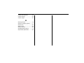
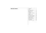
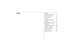
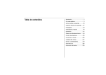
Table of Contents
Introduction .........................................1
In brief .................................................3
Keys, doors and windows.................17
Seats, restraints................................35
Storage..............................................59
Instruments and controls ..................71
Lighting............................................107
Infotainment system........................115
Climate controls ..............................185
Driving and operating......................197
Vehicle care ....................................229
Service and maintenance ...............297
Technical data.................................309
Customer information .....................317
Memo
Introduction
Introduction
When this Owner’s Manual refers to
a repairer visit, we recommend your
Chevrolet Service Partner.
Introduction
All Chevrolet Service Partners
provide first-class service at
reasonable prices. Experienced
mechanics trained by Chevrolet work
according to specific Chevrolet
instructions.
Your vehicle is a designed
combination of advanced
technology, safety, environmental
friendliness and economy.
This Owner’s Manual provides you
with all the necessary information to
enable you to drive your vehicle
safely and efficiently.
The customer literature pack should
always be kept ready to hand in the
vehicle.
Make sure your passengers are
aware of the possible risk of accident
and injury which may result from
improper use of the vehicle.
Using this Manual
You must always comply with the
specific laws and regulations of the
country that you are in. These laws
may differ from the information in this
Owner’s Manual.
This manual describes all options
and features available for this
model. Certain descriptions,
including those for display and
menu functions, may not apply to
your vehicle due to model variant,
country specifications, special
equipment or accessories.
The "In brief" section will give you
an initial overview.
1
The table of contents at the
beginning of this manual and
within each chapter shows where
the information is located.
The index will enable you to
search for specific information.
The Owner’s Manual uses the
factory engine designations. The
corresponding sales designations
can be found in the chapter
"Technical data".
Directional data, e.g. left or right,
or front or back, always relate to
the direction of travel.
The vehicle display screens may
not support your specific
language.
2
Introduction
Danger, Warnings and
Cautions
{Danger
Text marked ? Danger provides
information on risk of fatal injury.
Disregarding this information may
endanger life.
{Warning
Text marked ? Warning provides
information on risk of accident or
injury. Disregarding this
information may lead to injury.
Caution
Text marked Caution provides
information on possible damage to
the vehicle. Disregarding this
information may lead to vehicle
damage.
We wish you many hours of
pleasurable driving
Chevrolet
In brief
In brief
Initial drive information
3
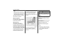
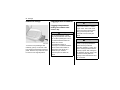
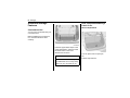
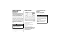
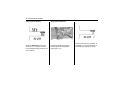
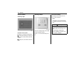
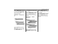
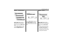
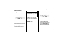
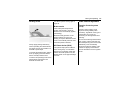
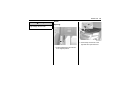
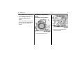
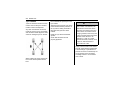
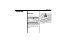
Seat adjustment
Seat positioning
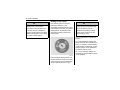
Unlocking the Vehicle
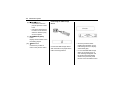
Radio remote control
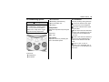
GO3E3014A
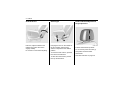
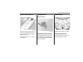
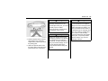
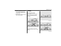
Press button K.
To move seat forward or backward,
pull the handle and slide seat to
desired position.
Unlocks all doors. Hazard lamps will
flash twice.
Release the handle and make sure
the seat is locked in place.
See Radio remote control on page
18.
See Seat adjustment on page 38.
TDL050A
See Central locking system on page
20.
See Seat position on page 37.
4
In brief
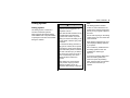
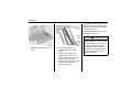
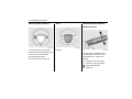
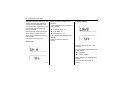
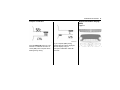
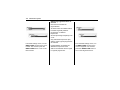
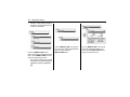
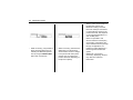
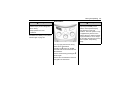
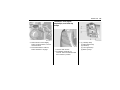
Seat backrests
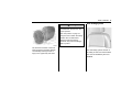
Head restraint adjustment
Seat height
Height adjustment
GO3E3015A
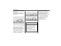
Pull lever, adjust inclination and
release lever. Allow the seat to
engage audibly.
Do not lean on seat when adjusting.
GO3E3016A
Pumping the lever on the outside of
the seat cushion until the seat
cushion is adjusted to the desired
position.
To lower the seat cushion, push the
lever down several times.
To raise the seat cushion, pull the
lever up several times.
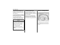
GO3E1003A
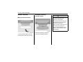
Pull the head restraint upwards.
To move down press the catch (1)
and push the head restraint
downwards.
See Head restraints on page 35.
In brief
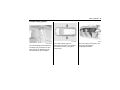
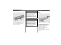
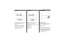
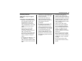
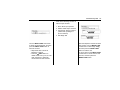
Safety Belt
Horizontal adjustment
5
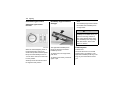
Mirror Adjustment
Interior mirrors
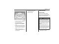
GO3E3002A
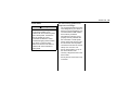
Pull the head restraint forwards. It is
adjusted to the three positions. To
move back pull the head restraint
forwards. Then it is moved
automatically backwards.
MD033
Withdraw belt from reel, guide it
untwisted across the body and
engage the latch plate in the buckle.
To reduce dazzle, pull the lever on
the underside of the mirror housing.
Tension the lap belt regularly whilst
driving by tugging the shoulder belt.
See Manual rearview mirror on page
28.
See Safety belts on page 41.
GO3E2007A
6
In brief
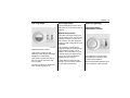
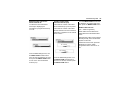
Steering Wheel Adjustment
Exterior mirrors
GC3N2006A
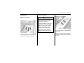
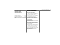
Select the relevant exterior mirror by
turning the control knob to left (L) or
right (R). Then swivel the control to
adjust the mirror.
When the position is in "o", mirror is
not selected.
See Remote control mirrors on page
27.
GC3N5001A
Unlock lever, adjust steering wheel,
then engage lever and ensure it is
fully locked. Do not adjust steering
wheel unless vehicle is stationary.
In brief
7
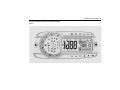
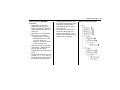
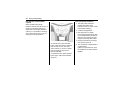
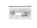
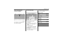
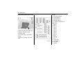
Instrument Panel Overview
LHD
GC3G1001A
8
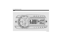
In brief
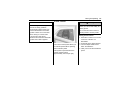
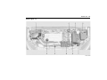
RHD
GC3G1001R
In brief
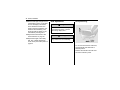
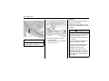
1. Side air vents
2. Exterior lamp switch
3. Turn signals
4. Cruise control
5. Cluster
6. Horn, Driver’s airbag
7. Steering wheel controls
8. Wiper and washer lever
9. Central air vents
10. Infotainment system
11. Storage
12. Passenger airbag ON-OFF
switch
13. Glove box
14. Passenger airbag ON-OFF light
15. Hazard warning flasher
16. Power outlet
17. Shift lever
18. Safety lock switch/HDC switch
19. Climate control system
20. ESC switch
21. Accelerator pedal
22. Brake pedal
23. Ignition switch
24. Steering wheel adjustment
25. Hood release lever
26. Clutch pedal
9
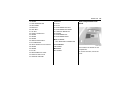
Exterior Lighting
GO3E6004A
Turn light switch knob.
O(OFF): To turn off all lamps, turn
the knob to OFF position. All lamps
are off and return knob to its original
AUTO position.
AUTO: Exterior lamps and
instrument panel lamps are
automatically turned on or off
depending on external lighting
conditions.
10
In brief
; : The tail lamps, number plate
lamps, and instrument panel lamps
are illuminated.
Headlamp high/low-beam
changer
Hazard warning flashers
2 : The headlamps and all of the
above lamps are illuminated.
Press light switch
#: Front fog lamp
s: Rear fog lamp
See Exterior lamp controls on page
107.
GC3N6001A
JD13A
To switch from low to high beam,
push lever.
To switch to low beam, push lever
again or pull.
See Headlamp high/low-beam
changer on page 108.
See Flash-to-pass on page 108.
Operated with the | button.
See Hazard warning flashers on
page 109.
In brief
Turn and lane-change signals
Horn
11
Washer and Wiper Systems
Windshield wiper
JD14A
lever up = right indicator
GC3N5003A
Press Y
TDL033A
lever down = left indicator
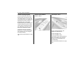
2: Continuous wipe, fast speed.
See Turn and lane-change signals
on page 110.
1: Continuous wipe, slow speed.
3: Intermittent operation.
O: System off.
3: Misting function.
For a single swipe when the
windshield wipers are off, lightly
move the lever down and release it.
12
In brief
See Windshield wiper/washer on
page 72.
Rear window wiper/washer
Washer
Wiper
Windshield washer
TDL031A
TEL021A
TDL030A
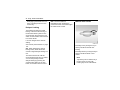
Pull lever.
See "Windshield washer" under
Windshield wiper/washer on page
72.
See Washer fluid on page 246.
Press the upward of switch to
operate wiper continue.
Press the downward of switch to
operate wiper interval.
To turn off the wiper set the switch in
neutral.
See Rear window wiper/washer on
page 74.
Push the lever toward the instrument
panel.
Washer fluid is sprayed onto the rear
window and the wiper swipes for a
few strokes.
See Rear window wiper/washer on
page 74.
See Washer fluid on page 246.
In brief
Climate control
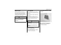
Heated rear window, heated
exterior mirrors
Demisting and defrosting the
windows
13
Transmission
Manual transmission
GC3E8003A
GC3N9007A
GC3N2011A
Operated by pressing the = button.
See Heated mirrors on page 27.
See Heated rear window on page 31.
Turn the air distribution knob to
DEFROST 5.
See "Defrosting windshield" under
Heating and ventilation system on
page 185.
See "Demisting windshield" under Air
conditioning system on page 189.
To engage reverse, with the vehicle
stationary pull up the button on the
selector lever and engage the gear.
If the gear does not engage, set the
lever in neutral, release the clutch
pedal and depress again; then
repeat gear selection.
See Manual transmission on page
211.
14
In brief
Automatic transmission
MD174
Push the release button to shift.
Arrows indicate shifts that do not
require you to push the release
button.
GC3N9003A
P (PARK): Locks the front wheels.
Select P only when the vehicle is
stationary and the parking brake is
applied.
MD172
Depress the brake pedal and push
release button to shift.
R (REVERSE): Select R only when
the vehicle is stationary.
Shifts that require you to push the
release button are indicated by
arrows.
N (NEUTRAL): Neutral gear.
D: For all normal driving conditions.
Allows the transmission to shift into
all 6 forward gears.
M: Manual mode position.
TDL148A
In brief
Getting Started
Check before starting off
15
Starting engine with the
ignition switch
Tyre pressure and condition.
Engine oil level and fluid levels.
MD173
Shift freely.
All windows, mirrors, exterior
lighting and number plates are
free from dirt, snow and ice and
are operational.
Proper position of seats, safety
belts and mirrors.
Check brake function at low
speed, particularly if the brakes
are wet.
MD098
Turn the key to position 1, move
the steering wheel slightly to
release the steering wheel lock
Manual transmission: operate
clutch
Automatic transmission : Move
selector lever to P or N.
Do not accelerate
16
In brief
Diesel engine: turn the key to
position 2 for preheating until K
goes out.
Turn the key to position 3,
depressing the clutch pedal and
footbrake then release when
engine is running
Before restarting or to switch off the
engine, turn key back to 0.
Parking
Do not park the vehicle on an
easily flammable surface. The
high temperature of the exhaust
system could ignite the surface.
Always apply parking brake
without pressing release button.
Apply as firmly as possible on
downhill or uphill slopes. Depress
the footbrake at the same time to
reduce operating force.
Switch off the engine and ignition.
Turn the steering wheel until the
steering wheel lock engages.
If the vehicle is on a level surface
or uphill slope, engage first gear
or "P" position before switching
off the ignition. On an uphill
slope, turn the front wheels away
from the kerb.
If the vehicle is on a downhill
slope, engage reverse gear
before switching off the ignition.
Turn the front wheels towards the
kerb.
Close windows.
Lock the vehicle.
Keys, doors and windows
Keys, doors and
windows
Keys and locks
17
Key with foldaway key section
Keys
Replacement keys
Keys and locks ..............................17
Doors .............................................23
Vehicle security .............................25
Exterior mirrors ..............................26
Interior mirrors ...............................28
Windows ........................................29
Roof ...............................................32
The key number is specified on a
detachable tag.
The key number must be quoted
when ordering replacement keys as
it is a component of the immobiliser
system.
See "Lock" under Exterior care on
page 289.
TDL046A
Press button to extend.
To fold the key, press the button and
fold the key manually.
18
Keys, doors and windows
Radio remote control
Handle with care, protect from
moisture and high temperatures and
avoid unnecessary operation.
Fault
If the central locking system cannot
be operated with the radio remote
control, it may be due to the
following:
Range exceeded,
Battery voltage too low,
Frequent, repeated operation of
the remote control while not in
range, which will require
resynchronisation,
TDL048A
Used to operate:
Central locking system
Anti-theft alarm system
The radio remote control has an
approximate range of up to 20
metres. This range can be affected
by outside influences.
The hazard warning flashers confirm
operation.
Overload of the central locking
system by operating at frequent
intervals, the power supply is
interrupted for a short time,
Interference from higher-power
radio waves from other sources.
Keys, doors and windows
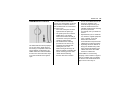
Radio remote control battery
replacement
Replace the battery as soon as the
range is noticeably diminished.
Batteries do not belong in household
waste. They must be disposed of at
an appropriate recycling collection
point.
Key with foldaway key section
1. Open the transmitter cover.
2. Remove the used battery. Avoid
touching the circuit board to other
components.
3. Install the new battery. Be sure
the negative side (-) faces down
toward the base.
4. Close the transmitter cover.
5. Check the operation of the
transmitter with your vehicle.
Caution
Avoid touching the flat surfaces of
the battery with your bare fingers.
Handling will shorten battery life.
Note
Used lithium batteries can harm
the environment.
TDL055A
Note
Use CR2032 (or equivalent)
replacement battery.
Follow local recycling laws for
disposal.
Do not discard with household
waste.
19
Note
In order to keep the transmitter
working properly, follow these
guidelines:
Avoid dropping the transmitter.
Do not place heavy objects on the
transmitter.
Keep the transmitter away from
water and direct sunlight. If the
transmitter gets wet, wipe it with a
soft cloth.
20
Keys, doors and windows
Central locking system
Central locking button
You can activate the central door
locking system from the front door.
This system allows you to lock and
unlock all the doors, the tailgate and
fuel filler door from the driver’s or
passenger’s door, using either
keyless remote (from outside) or the
central locking button (from inside).
<Driver’s door>
<Passenger’s door>
The key (from outside) and driver’s
door sill locking knob (from inside)
allows only central door locking.
If the driver's door is not closed
properly, the central locking system
can not work. It can be changed in
the Vehicle Setting.
See Vehicle personalization on page
102.
GC3N2002A
GC3N2001A
Locks or unlocks all doors, the
tailgate and fuel filler door.
Press button Q to lock.
Press button K to unlock.
If the driver's door is opened, driver’s
door and fuel filler door cannot be
locked. It can be changed in the
Vehicle Setting.
See Vehicle personalization on page
102.
Keys, doors and windows
21
Unlocking
Locking
Deadlock
Radio remote control
Radio remote control
For further protection when leaving
the vehicle, you can deadlock the
doors.
Deadlocking electronically jams all
the electric locks so that no door can
be opened, even if entry is gained by
breaking glass.
{Warning
TDL050A
TDL052A
Press button K.
Press button Q.
Unlock all doors.
Lock all doors.
Hazard lamps will flash twice.
If unlock driver's door only or change
the unlock feedback, it can be
changed in the Vehicle Setting.
See Vehicle personalization on page
102.
Do not use deadlocking if there are
people in the vehicle. The doors
cannot be unlocked from the
inside.
To engage deadlock, press button Q
on the radio remote control twice in
succession within 5 seconds.
To disengage deadlock, press button
K on the radio remote control.
Note
Deadlock function operates when
all doors, the tailgate and fuel filler
door are closed.
22
Keys, doors and windows
Disengaging the deadlock occurs
when unlocking the doors in the
normal way.
OFF: The doors will lock
immediately when pressing the
power lock switch or the button Q on
the radio remote control.
Manual Door Locks
Delayed Locking
This feature will delay the actual
locking of the doors and arming of
the anti-theft alarm system for five
seconds when the power door lock
switch or radio remote control is used
to lock the vehicle.
It can be changed in the Vehicle
Setting.
See Vehicle personalization on page
102.
ON: When pressing the central
locking button, three chimes are
sounds to signal delayed locking is in
use.
The doors will not lock until five
seconds after the last door is closed.
You can temporarily override
delayed locking by pressing the
central locking button or the lock
button on the radio remote control.
GO3E2014A
Manually lock by turning the key in
the key slot allows central door
locking.
Manually unlock by turning the key in
the key slot allows driver’s door
unlock.
Note
Tap the key slot or heat the key if
the door does not open with
freezing key slot in cold weather.
Keys, doors and windows
23
Doors
Safety locks
Caution
Tailgate
Do not pull the inside door handle
while the child security door lock is
set to LOCK position. To do so can
damage the inside door handle.
Opening
{Warning
Use the child security door locks
whenever children are occupying
the rear seats.
TDL002A
You can use a key or suitable
screwdriver.
To operate the child security door
lock, turn the child locks into
horizontal position.
To open a rear door when the child
security door lock is activated, open
the door from the outside.
To cancel the child security door
lock, turn the child locks into vertical
position.
GC3G2001A
To open the tailgate, push the
touchpad when the tailgate is
unlocked.
The tailgate is locked or unlocked
when all doors are locked or
unlocked with the radio remote
control or central locking button.
24
Keys, doors and windows
{Warning
Do not drive with the tailgate open
or ajar, e.g. when transporting
bulky objects, since toxic exhaust
gases could enter the vehicle.
Note
Closing
The installation of certain heavy
accessories onto the tailgate may
affect its ability to remain open and
opening performance.
To close the tailgate, push it down so
it latches securely.
Do not press the touchpad while
closing. It can cause opening again.
Caution
Caution
Before opening the tailgate check
overhead obstructions, such as a
garage door, to avoid damage of
the tailgate. Always check the
moving area above and behind the
tailgate.
Note
When engine is running, tailgate
can open with shift lever in "P"
position (automatic transmission) /
parking brake is engaged (manual
transmission).
Make sure your hands and any
other body parts, as well as those
of other persons are completely
away from the tailgate closure
area.
Keys, doors and windows
Vehicle security
The anti-theft alarm system is active
directly.
Anti-theft alarm system
Activation
25
Deactivation
Unlocking the vehicle by pressing
button K on the radio remote control
deactivates anti-theft alarm system.
Alarm
The alarm can be silenced by
pressing any button of the radio
remote control or by switching on the
ignition.
The anti-theft alarm system can be
deactivated by pressing the button K
or switching on the ignition.
GC3N2005A
TDL052A
Press button Q on the radio remote
control.
The anti-theft alarm system is active
automatically after 30 seconds.
Press button Q on the radio remote
control twice.
The indicator flashes quickly during
initial 30 seconds and then starts
flash slowly.
If the indicator still flashes quickly
after initial 30 seconds, driver's doors
is not completely closed or system
fault.
Seek the assistance of a repairer.
Auto door lock
If any of the door is not opened or the
position of Ignition key is not located
in ACC or ON within 3 minutes after
unlocking doors using the
transmitter, all the doors are locked
and anti-theft alarm system is
activated automatically.
26
Keys, doors and windows
Automatic door unlocks
All doors will be automatically
unlocked when the impact is
delivered to impact sensors while the
ignition is ON.
However, the doors may not be
unlocked if mechanical problems
occur with the door lock system or
battery.
Immobiliser
The immobiliser system provides an
additional theft deterrent to your
vehicle in which it is installed and
prevents it from being started by
unauthorised persons. The valid key
for a vehicle equipped with
immobiliser system is an ignition key
with integrated transponder, which is
electronically coded. The
transponder is placed invisibly in the
ignition key.
Only valid ignition keys can be used
to start the engine.
Invalid keys may only open the
doors.
Exterior mirrors
The engine is automatically
immobilised after the key is turned to
LOCK and has been removed from
the ignition switch.
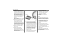
Convex mirror
If the immobiliser system detects a
fault when the ignition switch is in ON
position, the immobiliser indicator will
flash or illuminate and engine will not
start.
Have the vehicle checked, we
recommend an authorised repairer.
Note
Tap the key slot or heat the key if
the door does not open with
freezing key slot in cold weather.
The convex exterior mirror reduces
blind spots. The shape of the mirror
makes objects appear smaller, which
will affect the abilty to estimate
distances.
Keys, doors and windows
Remote control mirrors
Folding mirrors
27
Heated mirrors
Manual folding
GC3N2006A
Select the relevant exterior mirror by
turning the control knob to left (L) or
right (R). Then swivel the control to
adjust the mirror.
When the position is in "o", mirror is
not selected.
GC3N2011A
GC3N2007A
For pedestrian safety, the exterior
mirrors will swing out of their normal
mounting position if they are struck
with sufficient force. Reposition the
mirror by applying slight pressure to
the mirror housing.
Operated by pressing the + button.
Heating works with the engine
running and is switched off
automatically after a few minutes or
by pressing the button again.
28
Keys, doors and windows
Interior mirrors
Automatic dimming
rearview mirror
{Warning
Manual rearview mirror
Your view through the mirror may
lose some clarity when it is
adjusted for night vision.
Take special care with using your
inside rearview mirror when it is
adjusted for night vision.
Failure to ensure a clear rear view
while driving may result in a
collision causing damage to your
vehicle or other property, and/or
personal injury.
GO3E2008A
GO3E2007A
To reduce dazzle, pull the lever on
the underside of the mirror housing.
Dazzle from following vehicles at
night is automatically reduced.
Keys, doors and windows
Windows
29
Power windows
{Warning
Manual windows
Take care when operating the
power windows. Risk of injury,
particularly to children.
If there are children on the rear
seat, switch on the child safety
system for the power windows.
Keep a close watch on the
windows when closing them.
Ensure that nothing becomes
trapped in them as they move.
GO3E2009A
The door windows can be opened or
closed with the window winders.
GC3N2009
Power windows can be operated with
ignition ON.
Operate the switch for the respective
window by pushing to open or pulling
to close.
30
Keys, doors and windows
Operation
You may operate the power windows
when the ignition switch is ON by
using the power window switches on
each door panel.
To open the window, press down on
the switch.
To close the window, lift up on the
switch.
Release the switch when the window
reaches the desired position.
{Warining
Body parts outside vehicle can be
struck by passing objects. Keep all
parts of body inside vehicle.
Children can operate and become
entrapped in power windows.
Do not leave your keys or
unattended children in your car.
Serious injury or death can occur
from misuse of power windows.
Auto up/down
To fully open the window
automatically, press the switch fully
down. To fully close the window
automatically, pull the switch fully up.
In automatic operation, the window
will fully open or close even if you
let go of the switch.
To stop the window at the desired
position while the window is in
operation, pull up or press down and
release the switch to the opposite
direction of the movement.
Anti-pinch function
In case there is obstacle detection
while the driver's window is closed
automatically, the window will be
opened automatically for safety.
Initializing the power windows
If the windows cannot be closed
automatically (e.g. after
disconnecting the vehicle battery),
activate the window electronics as
follows:
1. Close doors.
2. Switch on ignition.
3. Close the window completely and
keep the switch pulled for
additional 2 seconds.
4. Repeat for each window.
{Warining
Anti-pinch function may not
operate after several times
operation.
Do not operate the window switch
with no purpose.
Keys, doors and windows
Child safety system for rear
windows
Heated rear window
31
Caution
Do not use sharp instruments or
abrasive window cleaners on your
rear window.
Do not scratch or damage the
defroster wires when you clean or
work around the rear window.
GC3N2011A
GC3N2010
Press switch v to deactivate rear
power windows.
To activate press v again.
Operated by pressing the + button.
Heating works with the engine
running and is switched off
automatically after a few minutes or
by pressing the button again.
32
Keys, doors and windows
Sun visors
Roof
The sun visors can be folded down
or swivelled to the side to prevent
dazzling.
Sunroof
The sun visors have mirror covers
should be closed when driving.
If the sun visors have vanity mirror
lamp, the lamp will illuminate when
opening the vanity mirror cover.
{Warining
Do not place the sun visor in such
a manner that it obscures visibility
of the roadway, traffic or other
objects.
{Warining
Take care when operating the
sunroof. There is risk of injury,
particularly to children.
Keep a close watch on the
movable parts when operating
them. Ensure that nothing
becomes trapped in them as they
move.
Sunroof can be operated with ignition
ON.
GO3E2013A
Open/Close
To open the desired position, press
lightly and hold the switch (1).
Release the switch when the sunroof
reaches the desired position.
To close the sunroof, press light and
hold the switch (2) until the sunroof is
closed.
Keys, doors and windows
Tilt Open/Close
To open the sunroof with tilting,
press the switch (3).
To close the sunroof, press the
switch (4).
Auto open/close
To open the sunroof automatically,
press firmly and release the switch
(1). To stop movement, press any of
the switches once more.
To close the sunroof automatically,
press firmly and release the switch
(2). To stop movement, press any of
the switches once more.
Safety function
If the sun roof encounters resistance
during automatic closing, it is
immediately stopped and opened
again.
Sunblind
The sunblind is operated manually.
Close or open the sunblind by
sliding.
When the sunroof is open, the
sunblind is always open.
{Warining
Body parts outside vehicle can be
struck by passing objects. Keep all
parts of body inside vehicle.
Serious injury or death can occur
from misuse of sunroof.
33
Dirt and debris may collect on the
sunroof seal or in the track that could
cause an issue with sunroof
operation, noise or plug the water
drainage system.Periodically open
the sunroof and remove any
obstacles or loose debris. Wipe the
sunroof seal and roof sealing area
using a clean cloth, mild soap, and
water. Do not remove grease from
the sunroof.
Memo
Seats, restraints
Seats, restraints
35
Head restraints
Head restraints
Head restraints ..............................35
Position
Front seats ....................................37
Safety belts....................................41
Airbag system................................45
Child restraints ..............................51
{Warning
Only drive with the head restraint
set to the proper position.
Removed or improperly adjusted
head restraints can result in
serious head and neck injuries in
case of a collision.
Make sure that the head restraint
readjusted before driving.
MD024
The middle of the head restraint
should be at eye level. If this is not
possible for extremely tall people, set
to highest position, and set to lowest
position for small people.
36
Seats, restraints
Head restraints on front seats
Head restraints on rear seats
Horizontal adjustment
Height adjustment
Height adjustment
GO3E3002A
GO3E3001A
Pull the head restraint upwards.
To move down press the catch (1)
and push the head restraint
downwards.
Pull the head restraint forwards. It is
adjusted to the three positions. To
move back pull the head restraint
forwards. Then it is moved
automatically backwards.
GO3E3003A
Pull the head restraint upwards.
To move down press the catch (1)
and push the head restraint
downwards.
Removing
Removing
Raise head restraint fully height.
Raise head restraint fully height.
Press the catches (1) and (2) at the
same time.
Press the catches (1) and (2) at the
same time.
Pull up the head restraint.
Pull up the head restraint.
Seats, restraints
Front seats
Rear headrest non-use
position
Seat position
{Warning
Only drive with the seat correctly
adjusted.
37
Sit with your buttocks as far back
against the backrest as possible.
Adjust the distance between the
seat and the pedals so that your
legs are slightly angled when you
fully depress the pedals. Slide the
passenger seat as far back as
possible.
Sit with your shoulders as far
back against the backrest as
possible. Set the backrest angle
so that you can easily reach the
steering wheel with your arms
slightly bent. Maintain contact
between your shoulders and the
backrest when turning the
steering wheel. Do not tilt the
backrest too far back. We
recommend a maximum angle of
approx. 25.
GO3E3022A
When the rear headrest is at the
pull-down position, this is the
non-use position of headrest.
MD028
Adjust the steering wheel. See
Steering wheel adjustment on
page 71.
38
Seats, restraints
Set the seat high enough to have
a clear field of vision on all sides
and on all display instruments.
There should be at least one
hand of clearance between your
head and the headlining. Your
thighs should rest lightly on the
seat without pressing into it.
Adjust the head restraint. See
Head restraints on page 35.
Adjust the height of the safety
belt. See "Height adjustment"
under Three-point safety belts on
page 43.
Seat adjustment
Seat positioning
{ Danger
Do not sit nearer than 25 cm(10in)
to the steering wheel, to permit
safe airbag deployment.
{Warning
Never adjust seats while driving as
they could move uncontrollably.
GO3E3014A
To move seat forward or backward,
pull the handle and slide seat to
desired position.
Release the handle and make sure
the seat is locked in place.
Seats, restraints
Seat backrests
Pull lever, adjust inclination and
release lever. Allow the seat to
engage audibly.
Note
Do not lean on seat when
adjusting.
Heated front seats
Seat height
GO3E3015A
39
GO3E3016A
Pumping the lever on the outside of
the seat cushion until the seat
cushion is adjusted to the desired
position.
To lower the seat cushion, push the
lever down several times.
To raise the seat cushion, pull the
lever up several times.
GC3N3008A
The seat heater buttons are located
in the climate control.
Seat heating is operational when the
engine is running.
To warm the seat, press the button
that you want to warm.
Indicator in the button will be
illuminated.
To turn the seat heater off, press the
button again.
40
Seats, restraints
{Warning
If you cannot feel temperature
change or pain to the skin, the seat
heater may cause burns even at
low temperatures.
To reduce the risk of burns, people
with such a condition should use
care when using the seat heater,
especially for long periods of time.
Do not place anything on the seat
that insulates against heat, such as
a blanket, cushion, cover or similar
item. This may cause the seat
heater to overheat. An overheated
seat heater may cause a burn or
may damage the seat.
Folding seatback
Front passenger’s seat
{Warning
If you fold the seatback forward to
carry longer objects, such as skis,
be sure any such cargo is not near
an airbag. In a crash, an inflating
airbag might force that object
toward a person. This could cause
severe injury or even death.
Secure object away from the area
in which an airbag would inflate.
Things you put on this seatback
can strike and injure people in a
sudden stop or turn, or in a crash.
Remove or secure all items before
driving.
GC3N3007A
To fold the seatback,
1. Lower the head restraint all the
way.
2. Pull up and hold the lever under
the front of the seat to slide the
seat as far back as it will go and
release the lever.
3. Lift the recliner lever (1) up fully
and fold the seatback (2) forward
until it is locked.
Seats, restraints
To raise the seatback,
1. Lift the seatback and push to
original position.
2. Latch the seatback into place by
pushing on the top of the
seatback.
3. Pull the seatback forward again
to make sure the seatback is
properly latched.
Safety belts
{Warning
Safety belts
Fasten safety belt before each trip.
In the event of an accident, people
not wearing safety belts endanger
their fellow occupants and
themselves.
Safety belts are only designed for
use by one person at a time. They
are not suitable for people younger
than 12 years of age or smaller than
150 cm(5 ft).
Caution
If the seatback is not locked, it
could move forward in a sudden
stop or crash.
That could cause injury to the
person sitting there. Always push
and pull on the seatback to be sure
it is locked.
41
MD033
The belts are locked during heavy
acceleration or deceleration of the
vehicle for the safety of the
occupants.
Periodically check all parts of the belt
system for damage and proper
functionality.
Have damaged components
replaced. After an accident, have the
belts and triggered belt tensioners
replaced by a repairer.
42
Seats, restraints
Note
Make sure that the belts are not
damaged by shoes or sharp-edged
objects or trapped. Prevent dirt
from getting into the belt retractors.
Safety belt reminder >. See Safety
belt reminders on page 85.
Pre-tensioners work only once. If the
pre-tensioners activate in a crash,
the pre-tensioners and probably
other new parts of the vehicle’s
safety belt system will be need to be
replaced.
Incorrect handling (e.g. removal or
fitting of belts or belt buckles) can
trigger the belt tensioners with risk
of injury.
Deployment of the belt tensioners is
indicated by illumination of control
indicator 9.
Belt force limiters
In the front seats, stress on the body
is reduced by the gradual release of
the belt during a collision.
See Airbag and safety belt tensioner
light on page 86.
Triggered belt tensioners must be
replaced by a repairer. Belt
tensioners can only be triggered
once.
Belt tensioners
This vehicle has safety belt
pre-tensioners for front outboard
occupants. Although the safety belt
pre-tensioners cannot be seen, they
are part of the safety belt assembly.
They can help tighten the safety belts
during the early stages of a moderate
to severe frontal and near frontal
crash if the threshold conditions for
pre-tensioner activation are met.
{Warning
Note
GO3E3017A
In the event of a head-on or side or
rear-end collision of a certain
severity, the front safety belts are
tightened.
Do not affix or install accessories
or other objects that may interfere
with the operation of the belt
tensioners.
Seats, restraints
Do not make any modifications to
belt tensioner components as this
will invalidate the vehicle type
approval.
43
Three-point safety belts
Fitting
{Warning
Do not bleach or dye safety belts. It
may severely weaken them. In a
crash, they might not be able to
provide adequate protection.
Clean safety belts only with mild
soap and lukewarm water.
MD036
MD035
Withdraw belt from reel, guide it
untwisted across the body and
engage the latch plate in the buckle.
Tension the lap belt regularly while
driving by tugging the shoulder belt.
Loose or bulky clothing prevents the
belt from fitting snugly. Do not place
objects such as handbags or mobile
phones between the belt and your
body.
{Warning
The belt must not rest against hard
or fragile objects in the pockets of
your clothing.
44
Seats, restraints
Height adjustment on front
seat safety belts
Safety belt use during
pregnancy
Removing
{Warning
The belt must be positioned as low
as possible across the pelvis to
prevent pressure on the abdomen.
Safety belts work for everyone,
including pregnant women.
MD038
GO3E3005A
1. Press button.
2. Adjust height and engage.
Adjust the height so that the belt lies
across the shoulder. It must not lie
across the throat or upper arm.
{Warning
Do not adjust while driving.
To release belt, press red button on
belt buckle.
Safety belts on the rear seats
The three point safety belt for the
rear central seat can only be
withdrawn from the retractor if the
backrest is in the rear position.
Like all occupants, pregnant women
are more likely to be seriously injured
if they do not wear safety belts.
In addition, when a safety belt is
worn properly, it is more likely that
the unborn child will be safe in a
crash.
To provide maximum protection, a
pregnant woman should wear a
safety belt.
She should wear the lap portion of
the belt as low as possible
throughout her pregnancy.
Seats, restraints
Airbag system
Airbag system
The airbag system consists of a
number of individual systems.
When triggered the airbags inflate
within milliseconds. They also deflate
so quickly that it is often unnoticeable
during the collision.
{Warning
If handled improperly the airbag
systems can be triggered in an
explosive manner.
The driver should sit back as far as
possible while still maintaining
control of the vehicle. If you are
sitting too close to the airbag, it can
cause death or serious injury when
it inflates.
For maximum safety protection in
all types of crashes, all occupants
including the driver should always
wear their safety belts to minimize
the risk of severe injury or death in
the event of a crash. Do not sit or
lean unnecessarily close to the
airbag while the vehicle is in
motion.
The airbag may cause facial or
body scratch, injury by broken
glasses or getting a burn by
explosion while airbag is deployed.
45
Note
The airbag systems and belt
tensioner control electronics are
located in the central console area.
Do not put any magnetic objects in
this area.
Do not stick anything on the airbag
covers and do not cover them with
other materials.
Each airbag is triggered only once.
Have deployed airbags replaced
by a repairer.
Do not make any modifications to
the airbag system as this will
invalidate the vehicle type
approval.
In the event of airbag deployment
have the steering wheel, the
instrument panel, all panelling
parts, the door seals, the handles
and the seats removed by a
repairer.
46
Seats, restraints
When an air bag deploys, there
may be a loud noise and smoke.
These conditions are normal and
are not dangerous but in case it
may irritate skin of the passenger.
If the irritation is continued, contact
a doctor.
{Danger
Never allow children or infants and
pregnant women and the old and
the weak sit in the front passenger
seats fitted with airbags.
Furthermore, do not drive with a
baby seat fitted thereon. In case of
an accident, the impact from the
inflated airbag can cause facial
injury or death.
Caution
If the vehicle is impacted by bumps
or objects on unpaved roads or
sidewalks, the air bag may inflate.
Drive slowly on the surfaces not
designed for vehicle traffic to
prevent unintended air bag
deployment.
Front airbag system
The front airbag system consists of
one airbag in the steering wheel and
one in the instrument panel on the
passenger side. These can be
identified by the word AIRBAG.
Control indicator 9 for airbag
systems.
See Airbag and safety belt tensioner
light on page 86.
GO3E3007A
The front airbag system is triggered
in the event of an accident of a
certain severity in the depicted area.
The ignition must be ON.
Seats, restraints
{Warning
47
Side airbag system
Optimum protection is only
provided when the seat is in the
proper position.
See Seat position on page 37.
Keep the area in which the airbag
inflates clear of obstructions.
Wear the seat belt properly
fastened. Only then the airbag is
able to protect.
MD039
The forward movement of the front
seat occupants is retarded, thereby
considerably reducing the risk of
injury to the upper body and head.
GO3E3008A
The side airbag system consists of
an airbag in each front seat backrest.
This can be identified by the word
AIRBAG.
48
Seats, restraints
Note
Only use protective seat covers
that have been approved for your
vehicle. Be careful not to cover the
airbags.
{Warning
GO3E3006A
The side airbag system is triggered
in the event of an accident of a
certain severity. The ignition must be
ON.
MD041
The risk of injury to the thorax and
pelvis in the event of a side-on
collision is considerably reduced.
{Warning
Keep the area in which the airbag
inflates clear of obstructions.
Children who are seated in close
proximity to a side airbag may be
at risk of serious or fatal injury if the
airbag deploys, especially if the
child's head, neck, or chest is close
to the airbag at the time of
deployment.
Never let your child lean on the
door or close to the side airbag
module.
Seats, restraints
49
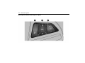
Curtain airbag system
GO3E3006A
GO3E3009A
The curtain airbag system consists of
an airbag in the roof frame on each
side. This can be identified by the
word AIRBAG on the roof pillars.
The curtain airbag system is
triggered in the event of an accident
of a certain severity. The ignition
must be ON.
MD043
The risk of injury to the head in the
event of a side impact is
considerably reduced.
50
Seats, restraints
{Warning
Keep the area in which the airbag
inflates clear of obstructions.
The hooks on the handles in the
roof frame are only suitable for
hanging up light articles of clothing,
without coat hangers. Do not keep
any items in these clothes.
Airbag on-off switch
{Warning
Front airbag system for the front
passenger seat have to be
deactivated if a child restraint system
is to be fitted on this seat. The curtain
airbag system, the belt tensioners
and all driver airbag systems will
remain active.
Deactivate front passenger airbag
system when the front passenger
seat is occupied by a child.
Activate front passenger airbag
system when an adult is on the
front passenger seat.
Use the ignition key to choose the
position:
U = front passenger airbags are
deactivated and will not inflate in the
event of a collision. Control indicator
U illuminates continuously. A child
restraint system can be installed in
accordance with the chart.
TEL014A
Front passenger airbag system can
be deactivated via a lock on the side
of the instrument panel, visible when
the front passenger door is open.
V = front passenger airbags are
activated. No child restraint systems
can be installed.
Seats, restraints
Child restraints
{Warning
Child restraint systems
When a child restraint system is
being used, pay attention to the
following usage and installation
instructions and also those supplied
with the child restraint system.
GC3G3001A
51
Always comply with local or national
regulations. In some countries, the
use of child restraint systems is
forbidden on certain seats.
As long as the control indicator U is
not illuminated, the airbag systems
for the front passenger seat will
inflate in the event of a collision.
NEVER use a rearward facing
child restraint on a seat protected
by an ACTIVE AIRBAG in front of
it, DEATH or SERIOUS INJURY to
the CHILD can occur.
{Warning
WARNING–EXTREME HAZARD
Do not use a rearward facing child
restraint on a seat protected by an
airbag in front of it.
The child could be seriously injured
if the airbag inflates, as the child's
head would be very close to the
inflating airbag.
Change status only when the vehicle
is stopped with the ignition off.
Status remains until the next change.
Control indicator for airbag
deactivation.
See Airbag on-off light on page 86.
GC3E3001A
52
Seats, restraints
{Warning
When using a child restraint
system on the front passenger
seat, the airbag systems for the
front passenger seat must be
deactivated; if not, the triggering of
the airbags poses a risk of fatal
injury to the child.
This is especially the case if
rearfacing child restraint systems
are used on the front passenger
seat.
Selecting the right system
The rear seats are the most
convenient location to fasten a child
restraint system.
Never carry a child while travelling in
the vehicle. The child will become too
heavy to hold in the event of a
collision.
Children should travel facing
rearwards in the vehicle as long as
possible. This makes sure that the
child's backbone, which is still very
weak, is under less strain in the
event of an accident.
When transporting children, use the
child restraint systems suitable for
the child’s weight.
Children under the age of 12 years
that are smaller than 150 cm (5 ft)
are only allowed to travel in a
restraint system that is suitable for
the child. Since a proper position of
the belt is rarely possible with a child
that is smaller than 150 cm (5 ft), we
strongly advise the use of an
appropriate child restraint system,
even though this might, due to the
age of the child, no longer be legally
binding.
Ensure that the mounting location of
the child restraint system within the
vehicle is correct.
Ensure that the child restraint system
to be installed is compatible with the
vehicle type.
Only allow children to enter and exit
the vehicle at the side facing away
from the traffic.
When the child restraint system is
not in use, secure the seat with a
safety belt or remove it from the
vehicle.
Note
Do not stick anything on the child
restraint systems and do not cover
them with any other materials.
Seats, restraints
A child restraint system which has
been subjected to stress in an
accident must be replaced.
Please ensure that infants and
children are seated in the rear
seats using child restraints.
Until the children can use safety
belts, please select a child restraint
suitable for its age and make sure
the child wears it. Please see the
instructions on the relevant
products for child restraints.
53
54
Seats, restraints
Child Restraint Installation Locations
Permissible options for fitting a child restraint system
On front passenger seat
Weight and age class
activated airbag
deactivated airbag
On rear outboard
seats
On rear central
seat1)
X
L2), U2)
L3), U3)
U3)
X
L2), U2)
L3), U3)
U3)
X
L2), U2)
L3), U3)
U3)
X
X
L3), U3)
X
X
X
L3), U3)
X
Group 0: up to 10 kg
or approx. 10 months
Group 0+: up to 13 kg
or approx. 2 years
Group I: 9 to 18 kg
or approx. 8 months to 4 years
Group II: 15 to 25 kg
or approx. 3 to 7 years
Group III: 22 to 36 kg
or approx. 6 to 12 years
1) CRS with support leg is not allowed due to incompatible vehicle floor such as Maxi cosi Cabriofix plus Easybase2
2) Only if front passenger seat airbag system is deactivated. If the child restraint system is being secured using a three-point seat
belt, move seat height adjustment to uppermost position and ensure that vehicle safety belt runs forwards from the upper
anchorage point. Adjust seat backrest inclination as far as necessary to a vertical position to ensure that the belt is tight on the
buckle side.
3) Move the head restraint to uppermost position. If it interferes with the proper installation of the child restraint system, remove
the headrest.
Seats, restraints
See Head restraints on page 35
Note
Move front seat to the foremost or adjust front seat backrest inclination as far as necessary to a vertical position to
ensure that there is no interference between child restraint system on rear seats and front seat backrest .
L: Suitable for particular child restraint systems of the "specific vehicle", "restricted" or "semi-universal" categories.
The restraint system must be approved for the" specific vehicle type", "restricted" or "semi-universal" categories.
U: Universal suitability in conjunction with three-point safety belt.
X: No child restraint system permitted in this weight class.
55
56
Seats, restraints
Permissible options for fitting an ISOFIX child restraint system
Weight class
Group 0: up to 10 kg
Group 0+: up to 13 kg
Group I: 9 to 18 kg
Size class
Fixture
On front
passenger seat
On rear
outboard seats
On rear
central seat
E
ISO/R1
X
IL1)
X
X
E
ISO/R1
X
IL1)
D
ISO/R2
X
IL1)
X
X
C
ISO/R3
X
IL1)
D
ISO/R2
X
IL1)
X
X
C
ISO/R3
X
IL2)
B
ISO/F2
X
IL, IUF
X
B1
ISO/F2X
X
IL, IUF
X
A
ISO/F3
X
IL, IUF
X
1) Move front seat to the foremost position or adjust front seat backrest inclination as far as necessary to a vertical position to
ensure that there is no interference between child restraint system and front seat backrest.
IL: Suitable for particular ISOFIX restraint systems of the "specific vehicle", "restricted" or "semi-universal" categories.
The ISOFIX restraint system must be approved for the" specific vehicle type", "restricted" or "semi-universal" categories.
IUF: Suitable for ISOFIX forward-facing child restraint systems of universal category approved for use in this mass
group.
X: No ISOFIX child restraint system approved in this weight class.
Seats, restraints
ISOFIX size class and seat device
A - ISO/F3: Forward-facing child restraint system for children of maximum size in the weight class 9 to 18 kg.
B - ISO/F2: Forward-facing child restraint system for smaller children in the weight class 9 to 18 kg.
B1 - ISO/F2X: Forward-facing child restraint system for smaller children in the weight class 9 to 18 kg.
C - ISO/R3: Rear-facing child restraint system for children of maximum size in the weight class up to 18 kg.
D - ISO/R2: Rear-facing child restraint system for smaller children in the weight class up to 18 kg.
E - ISO/R1: Rear-facing child restraint system for young children in the weight class up to 13 kg.
57
58
Seats, restraints
Isofix child restraint
systems
Top-tether fastening eyes
Top-Tether fastening eyes are
marked with the symbol I for a child
seat.
GO3E3011A
GC3N3004A
Fasten vehicle-approved ISOFIX
child restraint systems to the ISOFIX
mounting brackets. Specific vehicle
ISOFIX child restraint system
positions are marked in the table by
IL.
ISOFIX mounting brackets are
indicated by a label on the backrest.
The vehicle might be equipped with
guides in front of the mounting
brackets to support the installation of
the child restraint system. The lids of
the guides will swivel backwards
automatically when attaching the
olchild restraint system.
GO3E3013A
In addition to the ISOFIX mounting,
fasten the Top-Tether strap to the
Top-Tether fastening eyes. The strap
must run between the two guide rods
of the head restraint.
ISOFIX child restraint systems of
universal category positions are
marked in the table by IUF.
Storage
Storage
59
Storage compartments
Instrument panel storage
Storage compartments ..................59
Luggage/load locations .................62
Additional Storage Features ..........66
Roof Rack System.........................68
Information on loading the vehicle.69
GO3E4014A
GC3N4001A
It is located in the instrument panel.
To open the upper storage, slide the
latch.
It is located near the steering column
on the bottom of the instrument
panel.
To open, pull the handle.
60
Storage
Glovebox
Cupholders
GC3N4002A
It is located on top of the glove box.
To open, push the button.
GO3E4003A
To open, pull the grip.
It is used for small articles, etc.
To close, firmly push the storage
door shut.
{Warning
To reduce the risk of injury in an
accident or a sudden stop, always
keep the storages door closed
while driving.
{Warning
To reduce the risk of injury in an
accident or a sudden stop, always
keep the glovebox door closed
while driving.
GC3N4003A
Storage
{Warning
61
Sunglasses storage
Do not place uncovered cups of
hot liquid in the cup holder while
the vehicle is in motion. If the hot
liquid spills, you burn yourself.
Such a burn to the driver could
lead to loss of control of the
vehicle.
GO3E4005A
The cup holders are located in the
center console and the rear seat
armrest.
To use the rear seat cup holder, pull
the strap in the rear seat armrest.
To reduce the risk of personal
injury in the event of sudden stop
or collision, do not place
uncovered or unsecured bottles,
glasses, cans, etc., in the cup
holder while the vehicle is in
motion.
TDL063A
Fold down to open.
Caution
Do not use for storing heavy
objects.
62
Storage
Luggage/load locations
Underseat storage
Luggage compartment
Folding the seatback after
cushion flip
{Warning
Do not stack luggage or other
cargo higher than the front seats.
Do not allow passengers to sit on
the folded seatbacks while the
vehicle is in motion.
GO3E4006A
To use the front passenger seat
undertray, pull up on the end of the
tray and pull it toward the instrument
panel. Push the tray toward the seat
to return it to its original position.
Unrestrained luggage or
passengers on a folded seatback
can be thrown about within or
ejected from the vehicle in a
sudden stop or accident.
Serious injuries or death can
result.
{Warning
If either seatback is not locked, it
could move forward in a sudden
stop or crash. That could cause
injure to the person sitting there.
Always push and pull on the
seatbacks to be sure they are
locked.
{Warning
A safety belt that is improperly
routed, not properly attached or
twisted will not provide the
protection needed in a crash. The
person wearing the belt could be
seriously injured. After raising the
rear seatback, always check to be
sure that the safety belts are
properly routed and attached and
are not twisted.
Storage
To fold down the rear seatbacks :
Caution
Folding the rear seat backrest
before cushion flip, may cause
damage to the rear seat.
Always flip the cushion and fold the
rear seat backrest.
1. Push head restraints down by
pressing the catch.
Note
To ensure enough room for rear
seat cushion operation, slide the
front seat forward and adjust the
front seatback upright.
63
Note
Do not place anything in the floor.
It can cause improperly folding or
damage to the seat cushion.
Caution
Folding a rear seat with the safety
belts still fastened may cause
damage to the seat or the safety
belts. Always unbuckle the safety
belts and return them to their
normal stowed position before
folding a rear seat.
GO3E4009A
GO3E4007A
2. Pull the strap under the seat
cushion. Then, the seat cushion
is fallen automatically.
1. Pull the release lever on top of
the rear seatback.
64
Storage
The center rear safety belt may lock
when you raise the seatback. If this
happens, let the belt go back all the
way and start again.
If the safety belt still locked, try again
after pulling cushion out.
{Warning
GO3E4008A
2. Fold the seatback forward and
down.
GO3E4010A
3. Put the safety belts of the
outboard seats into the belt
guides.
4. To return the seatback to the
original position, pull out the
safety belt from the belt guides
and lift seatback up. Push
seatback firmly into place. Make
sure the safety belts are not
pinched by the latch.
To return the rear seat cushion, put
the rear part of the seat cushion in
its original position ensuring that
the safety belt buckle straps are
not twisted or caught under the
seat cushion, then push the front
part of the seat cushion firmly
down until it latches.
Storage
Caution
{Warning
When returning rear seatback to
the upright position, place the rear
safety belt and buckles between
the rear seatback and one cushion.
Make sure the rear safety belt and
buckles not to be pinched under
the rear seat cushion.
Ensure that the rear seatbacks are
all the way back and locked in
position before operating the
vehicle with passengers in the rear
seat.
Make sure the safety belts are not
twisted or caught in the seatback
and are arranged in their proper
position.
Do not pull the release levers on
the top of the seatback while the
vehicle is moving.
It can cause injuries or damage to
the occupants.
Caution
Folding a rear seat with the safety
belts still fastened may cause
damage to the seat or the safety
belts.
Always unbuckle the safety belts
and return them to their normal
stowed position before folding a
rear seat.
65
{Warning
Never allow passengers to sit on
top of the folded down seatback,
while the car is moving as this is
not a proper seating position and
no safety belts are available for
use.
This could result in serious injury or
death in case of an accident or
sudden stop.
Objects carried on the folded down
seatback should not extend higher
than the top of the front seats. This
could allow cargo to slide forward
and cause injury or damage during
sudden stops.
66
Storage
Additional Storage
Features
Rear Compartment/Storage
Panel Cover
Rear Compartment
Convenience Net
You can carry small loads with your
convenience net.
Before installing the convenience
net, read the instruction sheet
carefully.
GC3G4003A
Install the upper elastic loops to the
upper attachments, and then install
the lower hooks to the lower
attachments as shown.
Caution
GC3N4004A
You can place tools or spare tyre,
etc.
Pull the strap and lift it.
The convenience net is designed
for small loads. Do not carry heavy
objects in your convenience net.
Storage
Storage Panel Cover
Caution
Do not place heavy objects in
panel.
When lift the tailgate it lifted too,
keep clean panel to avoid objects
fall.
GO3E4024A
Fold the load floor and place the
hook into the shopping hook located
in the side trim as shown.
Note
If it is located in inappropriate
place may cause rattle noise and
wear by contact with rear seat.
GC3N4005A
You can place small objects or hide
items stored in the cargo area.
To use the panel, hang each loop to
both anchors of the tailgate.
When not in use, place the panel in
rear seat backward.
Note
If it is located in inappropriate
place may cause rattle noise and
wear by contact with rear seat.
67
68
Storage
Roof Rack System
Roof rack
Caution
{Warning
Ensure that the load is evenly
distributed over the side or cross
rails. The roof surface must not be
loaded.
If you try to carry something on top
of your vehicle that is longer or
wider than the roof rack, the wind
can catch it as you drive along.
This can cause you to lose control.
What you are carrying could be
violently torn off, and this could
cause you or other drivers to have
a collision, and of course damage
your vehicle.
A loaded luggage carrier alters the
vehicle's centre of gravity. Drive
carefully when in crosswinds and
do not drive at high speeds.
To prevent damage or loss of
cargo as you are driving, check
frequently to make sure your cargo
are securely fastened.
GC3E4001A
The roof rack can be used to
conveniently carry additional cargo,
or bulky items.
The roof rack has side rails attached
to the roof.
Consult an authorised repairer for
details and regulations on driving
with a loaded roof rack.
When you are carrying cargo on
the roof rack, do not operate the
sunroof.
Never carry something longer or
wider than the roof rack on top of
your vehicle.
A loaded roof rack changes the
vehicle's centre of gravity. Do not
drive at high speeds. Take
precautions when driving in
crosswinds.
Failure to follow this caution can
result in vehicle damage and
personal injury.
Storage
{Warning
The maximum load for the roof
rack rails is 165 lbs (75 kg). Do not
exceed the maximum vehicle
capacity when loading your
vehicle.
Information on loading
the vehicle
Information on loading the
vehicle
Heavy objects in the tailgate
should be placed against the seat
backrests. Ensure the backrests
are securely engaged. If objects
can be stacked, the heavier
objects should be placed at the
bottom.
Secure objects in tailgate to
prevent sliding.
When transporting objects in the
tailgate, the backrests of the rear
seats must not be angled
forward.
Do not allow the load to protrude
above the upper edge of the
backrests.
69
Do not place any objects on the
tailgate cover or the instrument
panel, do not cover the sensor on
top of the instrument panel.
The load must not obstruct the
operation of the pedals, parking
brake and gear selector, or
hinder the freedom of movement
of the driver. Do not place any
unsecured objects in the interior.
Do not drive with an open
tailgate.
The payload is the difference
between the permitted gross
vehicle weight (See Identification
plate on page 309) and the kerb
weight.
For the kerb weight in detail,refer
to the technical data section.
70
Storage
Driving with a roof load increases
the sensitivity of the vehicle to
cross-winds and has a
detrimental effect on vehicle
handling due to the vehicle’s
higher centre of gravity.
Distribute the load evenly and
secure it properly with retaining
straps. Adjust the tyre pressure
and vehicle speed according to
the load conditions. Check and
retighten the straps frequently.
Instruments and controls
Instruments and
controls
Controls
71
Caution
Steering wheel adjustment
Controls .........................................71
Warning lights, gauges and
indicators .......................................80
Information displays ......................93
Vehicle messages .........................98
Trip computer ................................99
Vehicle personalization ...............102
GC3N5001A
Unlock lever, adjust steering wheel,
then engage lever and ensure it is
fully locked.
Do not adjust steering wheel unless
vehicle is stationary.
If strong impact delivers to steering
column axle direction when the
steering wheel is adjusted or the
lever is locked, it may cause
damage to the parts related to
steering wheel.
72
Instruments and controls
Steering wheel controls
Horn
Windshield wiper/washer
Windshield wiper
GC3N5002A
The infotainment system and the
cruise control can be operated by the
controls on the steering wheel.
See Infotainment system.
See Cruise control on page 219.
GC3N5003A
Press Y
TDL033A
To operate the windshield wipers,
turn the ignition ON and move the
windshield wiper / washer lever
upward.
2: Continuous wipe, fast speed.
1: Continuous wipe, slow speed.
3: Intermittent operation.
O: System off.
Instruments and controls
3: Misting function.
Misting function
To operate the windshield wipers
once in case of light rain or mist,
lightly press the windshield wiper
/washer lever down and release it.
The lever will return automatically to
its normal position when released.
The wipers will operate through one
cycle.
Caution
73
Adjustable wiper interval
Less than clear vision for the driver
can lead to an accident resulting in
personal injury and damage to
your vehicle or other property.
Do not operate the windshield
wipers when the windshield is dry
or obstructed, as with snow or ice.
Using the wipers on an obstructed
windshield can damage the wiper
blades, wiper motor, and glass.
Check blades are not frozen to
windows before operating in cold
weather. Wiper operation while
blade is frozen can damage wiper
motor.
TDL032A
Turn the wheel to adjust the desired
wipe interval:
Short interval = turn adjuster wheel
upwards
Long interval = turn adjuster wheel
downwards
74
Instruments and controls
Windshield washer
Caution
Rear window wiper/washer
Wiper
Do not operate the windshield
washer continuously for more than
some seconds, or when the
washer fluid tank is empty. This
can cause the washer motor to
overheat resulting in costly repairs.
{Warning
TDL030A
Pull lever. Washer fluid is sprayed
onto the windshield and the wiper
swipes for one stroke.
Do not spray washer fluid on the
windshield in freezing weather.
Using washer fluid and wipers may
cause an accident in freezing
weather because washer fluid can
form ice on a frozen windshield
and obstruct your vision.
TEL021A
To operate the tailgate wiper, press
the switch in the end of the lever.
Press the upward of switch to
operate wiper continue.
Press the downward of switch to
operate wiper interval.
To turn off the wiper set the switch in
neutral.
Instruments and controls
Washer
Caution
Less than clear vision for the driver
can lead to an accident resulting in
personal injury and damage to
your vehicle or other property.
Do not operate the tailgate window
wiper when the tailgate window is
dry or obstructed, as with snow or
ice.
TDL031A
Push the lever toward the instrument
panel.
Washer fluid is sprayed onto the rear
window and the wiper swipes for a
few strokes.
Using the wiper on an obstructed
window can damage the wiper
blades, wiper motor, and glass.
Check blade is not frozen to
window before operating in cold
weather. Wiper operation while
blade is frozen can damage wiper
motor.
Do not spray washer fluid on the
tailgate window in freezing
weather.
Warm the tailgate window before
you operate the tailgate window
washer.
75
Caution
Washer fluid can form ice on a
frozen tailgate window and
obstruct your vision.
Do not operate the tailgate window
washer continuously for more than
some seconds, or when the
washer fluid tank is empty. This
can cause the washer motor to
overheat resulting in costly repairs.
76
Instruments and controls
Clock
Power outlets
<Type 2>
<Type 1>
GC3N5004A
GC3G5014A
Time and date are shown in the
infotainment display.
Settings for time and date can be
adjusted.
See Infotainment system.
GC3N5005A
A 12V power outlet is located in the
central console.
Do not exceed the maximum power
consumption of 120 watts.
Instruments and controls
Caution
Do not connect any current
delivering accessories, e.g.
electrical charging devices or
batteries.
Do not damage the sockets by
using unsuitable plugs.
{Warning
Sparks may occur when
connecting the unit to a power
source, this is normal.
Do not connect in the vicinity of
flammable or explosive
substances.
Do not start the engine where the
inverter is connected or running.
GC3N5006A
A 230V power outlet is located below
the backward of center console.
Do not exceed the maximum power
consumption of 150 watts.
With ignition off the power outlet is
deactivated.
Additionally the power outlet is
deactivated in case of low battery
voltage.
Note
Close the cover when not in use.
The inverter will not operate most
appliances designed to produce
heat, such as hair dryers, irons,
toasters, heaters and coffee
machines as these items drain
high amounts of current in excess
of 150 watts.
77
78
Instruments and controls
Cigarette lighter
Caution
Overheating the cigarette lighter
can damage the heating element
and the lighter itself.
Do not hold the lighter in while it is
heating. This can cause the lighter
to overheat.
Trying to operate a malfunctioning
cigarette lighter can be dangerous.
GC3G5001A
To operate the cigar lighter, turn the
ignition switch to ACC or ON and
push the lighter in all the way.The
cigar lighter will pop out
automatically when it is ready to use.
If the heated cigarette lighter does
not pop out pull it out and consult a
repairer to have it repaired. We
recommend that you consult your
authorised repairer. It can cause
injuries and damage to your
vehicle.
{Warning
If you leave the vehicle with an
inflammable explosive substance,
such as a disposable lighter, inside
the car in summer, it can explode
and cause fire due to an increase
of temperature in the passenger
compartment and the boot.
Please ensure that no inflammable
explosive substances are left or
kept inside the car.
Caution
The cigarette socket should only
be used with the cigarette lighter. If
other 12 V power adapters are
installed into the cigarette socket,
fuse failure or a potential thermal
incident may occur.
Instruments and controls
Caution
Ashtrays
79
The portable ashtray can be placed
in the cup holders.
To open the ashtray, gently lift the lid
of the ashtray. After using, close the
lid firmly.
The barrel of an operating cigarette
lighter can become very hot.
Do not touch the barrel of the
cigarette lighter and do not allow
children to operate or play with the
cigarette lighter.
To empty the ashtray for cleaning,
slightly rotate upper part of the
ashtray counterclockwise and
remove it.
This hot metal can cause personal
injuries and damage to your
vehicle or other property.
GC3G5002A
Caution
Cigarettes and other smoking
materials could set them on fire.
Do not put paper or other
flammable items in the ashtray.
An ashtray fire can lead to
personal injury or damage to your
vehicle or other property.
80
Instruments and controls
Warning lights, gauges
and indicators
Odometer
Speedometer
GC3G5015A
GC3N5016A
THR012A
Indicates vehicle speed.
The odometer shows how far your
car has been driven in kilometers or
miles.
There is independent trip odometer,
which measure the distance your
vehicle has travelled since you last
reset this function.
Each time you press the knob in the
cluster, the display changes in the
following order:
Odometer Trip odometer
Note
To reset trip odometer to zero,
press the knob for a few seconds.
Instruments and controls
Tachometer
81
Fuel gauge
Diesel
Petrol
GC3E5004A
GC3E5003A
Displays the engine revolutions per
minute.
Drive in a low engine speed range for
each gear as much as possible.
Caution
If the needle is in the warning
zone, the maximum permitted
engine speed is exceeded. Engine
is at risk.
TEL039A
Displays the fuel level in the tank.
Never run the tank dry.
Because of the fuel remaining in the
tank, the top-up quantity may be less
than the specified tank capacity.
Movement of the fuel within the fuel
tank causes the fuel gauge pointer to
move when you brake, accelerate or
turn.
82
Instruments and controls
{Danger
Before refueling, stop vehicle and
switch off the engine.
Service display
Control indicators
The control indicators described are
not present in all vehicles. The
description applies to all instrument
versions. The actual in the vehicle
may differ from the description.
When the ignition is switched on,
most control indicators will illuminate
briefly as a functionality test.
The control indicator colours mean:
red = danger, important reminder
yellow = warning, information, fault
green, bule, white = confirmation of
activation
Instruments and controls
83
Control indicators in the instrument cluster
Type 1
GC3E5001B
84
Instruments and controls
Type 2
GC3E5002B
Instruments and controls
Transmission display
Turn signal
Safety belt reminders
G flashes green.
> for driver’s seat illuminates or
flashes red.
Flashes
The control indicator flashes if a turn
signal or the hazard warning flashers
are activated.
Fast flashing
Failure of a turn signal lamp or
associated fuse.
See Bulb replacement on page 251.
See Fuses on page 258.
TGL023A
It indicates the selected gear or
transmission mode.
See Turn and lane-change signals
on page 110.
85
C for front passenger seat
illuminates or flashes, when seat is
occupied.
q>>>r for rear seats illuminate in
the Driver Information Center(DIC).
When the ignition switched ON, the
indicator light and warning chime
comes on and stay on for several
seconds to remind fasten safety
belts.
The light flashes until the safety belt
is buckled.
If safety belt remains unbuckled
when the vehicle is moving, lights
and chime repeat.
If the safety belt is buckled, light and
chime will go off.
See Three-point safety belts on page
43.
86
Instruments and controls
Airbag and safety belt
tensioner light
U for front passenger airbag
illuminates.
Airbag on-off light
When the control indicator
illuminates the front passenger
airbag is deactivated.
9 illuminates red.
When the ignition is switched on, the
control indicator illuminated for a few
seconds. If it does not illuminate,
does not go out after few seconds or
illuminates whilst driving, there is a
fault in the belt tensioner or in the
airbag system. The systems may fail
to trigger in the event of an accident.
Vehicle trouble or deployment of the
belt tensioners or airbags may be
indicated by continuous illumination
of 9.
{Warning
Have the cause of the fault
eliminated immediately by a
repairer.
See Airbag system on page 45.
See "Belt tensioners" under Safety
belts on page 41.
{Warning
If the both indicators remain on, or
both indicators go out, there is a
problem in the passenger airbag
status system.
GC3G3001A
The control indicators are in
instrument panel.
V for front passenger airbag
illuminates.
When the control indicator
illuminates the front passenger
airbag is activated and child or infant
seat should not be installed on the
front passenger seat.
Have the cause of the problem
eliminated immediately by a
repairer.
Instruments and controls
Charging system light
Caution
" illuminates red.
It illuminates when the ignition is
switched on and goes out shortly
after the engine starts.
Illuminates when the engine is
running
Stop, switch off engine. Battery is not
charging. Engine cooling may be
interrupted.
Seek the assistance of a repairer.
Malfunction indicator light
* illuminates yellow.
It illuminates when the ignition is
switched on and goes out shortly
after the engine starts.
If the indicator does not go out or if it
illuminates while driving, there is a
fault in the emission control system.
Have the vehicle checked by a
repairer.
The indicator light signals that your
vehicle has a problem that requires
attention.
Driving with the malfunction
indicator light on or flashing can
damage the emissions control
system and can affect the fuel
economy and drive ability of your
vehicle.
We recommend that you consult
your authorised repairer.
87
Service vehicle soon light
B illuminates when the vehicle
needs a service.
Have the vehicle checked by a
repairer immediately.
See Vehicle messages on page 98.
Apply clutch pedal light
# illuminates yellow.
It illuminates when clutch pedal
needs to be operated to restart the
engine.
See Automatic engine start/stop
feature on page 199.
88
Instruments and controls
Brake system warning light
$ illuminates red.
Illuminates when the parking brake is
released, if the brake fluid level is too
low or if there is a brake system fault.
See Brake fluid on page 247.
{Warning
Do not drive with the brake system
warning lamp on.
This may mean your brakes are
not working properly.
Driving with malfunctioning brakes
can lead to a collision resulting in
personal injuries and damage to
your vehicle and other property.
Illuminates after the ignition is
switched on if the manual parking
brake is applied.
See Parking brake on page 215.
Antilock brake system
(ABS) warning light
Hill descent control (HDC)
system light
! illuminates yellow.
5 illuminates green when system is
ready.
Illuminates for a few seconds after
the ignition is switched on. The
system is ready for operation when
the control indicator goes out.
If the control indicator does not go
out after a few seconds, or if it
illuminates while driving, there is a
fault in the ABS. The brake system
remains operational but without ABS
regulation.
See Antilock brake system (ABS) on
page 214.
Up-Shift Light
* illuminates when to shift to the
next higher gear for best fuel
economy.
See Manual transmission on page
211
5 blinks green when system is
activated.
See Ride control systems on page
215.
Power steering warning
light
E illuminates yellow.
It illuminates when the ignition is
switched on and goes out shortly
after the engine starts.
If the indicator does not go out after a
few seconds, or if it illuminates while
driving, there is a fault in the power
steering.
Seek the assistance of a repairer.
Instruments and controls
Electronic stability control
(ESC) indicator light
Electronic stability control
(ESC) off light
Fault due to sensors that are dirty
d illuminates or flashes yellow.
g illuminates yellow.
Covered by ice or snow
Illuminated
A fault in the system is present.
Continued driving is possible. Driving
stability, however, may deteriorate
depending on road surface
conditions.
Have the cause of the fault remedied
by a repairer.
Illuminates when the system is
deactivated.
Ultrasonic parking assist light
X illuminates yellow.
Outside ultrasonic waves
interference
When the source of interference is
removed, the system will operate
normally.
If the lamp does not go out, have the
cause of the fault in the system
remedied by a repairer.
Flashes
The system is actively engaged.
Engine output may be reduced and
the vehicle may be braked
automatically to a small degree.
Traction control (TC) off
light
i illuminates yellow.
Illuminate when the system is
deactivated.
Tyre pressure monitoring
system light
7 illuminates yellow.
It illuminates when the ignition is
switched on and goes out shortly
after the engine starts.
If the light comes on while driving,
the tyre pressure monitoring
system detects that one or more
of your tyres is significantly
under-inflated.
89
90
Instruments and controls
Stop the vehicle in safe place, check
tyres and inflate the tyres to the
recommended pressure on the tyre
inflation pressure label.
When the system detects a
malfunction, the light blinks for about
one minute and then stays on for the
remainder of the ignition cycle.
The malfunction light comes on until
the problem is corrected. Have the
vehicle checked by a repairer.
See Tyre Pressure Monitor
Operation on page 267.
Pre-Heating System and
Diesel Particle Filter Light
(Diesel only)
Engine coolant temperature
warning light
Preheating indicator light
This lamp tells you that the engine
coolant has overheated.
K illuminates yellow.
Illuminate when preheating is
activated. When the light goes out
the engine can be started.
Diesel particle filter indicator
light
L flashes yellow.
Flashes if the diesel particle filter
requires cleaning and previous
driving conditions did not permit
automatic cleaning. Continue driving
and if possible do not allow engine
speed to drop below 2000 rpm.
It goes off as soon as the self
cleaning operation is complete.
See Diesel particle filter on page
202.
C illuminates red.
If you have been operating your
vehicle under normal driving
conditions, you should pull off the
road, stop your vehicle and let the
engine idle for a few minutes.
If the lamp does not go out, you
should switch the engine off and
consult a repairer as soon as
possible. We recommend that you
consult your authorised repairer.
Instruments and controls
Engine oil pressure light
{Warning
: illuminates red.
It illuminates when the ignition is
switched on and goes out shortly
after the engine starts.
Illuminates when the engine is
running
Caution
Engine lubrication may be
interrupted. This may result in
damage to the engine and/or
locking of the drive wheels.
91
Low fuel warning light
. illuminates yellow.
When the engine is off,
considerably more force is needed
to brake and steer.
Do not remove key until vehicle
has come to a standstill, otherwise
the steering column lock could
engage unexpectedly.
Check oil level before seeking the
assistance of a repairer.
See Engine oil on page 238.
Illuminates when level in fuel tank is
too low.
Caution
Do not let your vehicle run out of
fuel.
This can damage the catalytic
converter.
See Catalytic converter on page 203.
Immobilizer light
If the engine oil pressure warning
lamp comes on while driving, pull off
the road, stop the engine and check
the oil level.
A illuminates yellow.
Illuminates when there is a fault. The
engine cannot be started.
Have the cause of the fault remedied
by a repairer.
92
Instruments and controls
Reduced Engine Power
light
Daytime running lamps
(DRL) light
Taillamp Indicator Light
w illuminates yellow.
i illuminates green.
It illuminates when the ignition is
switched on and goes out shortly
after the engine starts.
Illuminates when the daytime running
lamps are on.
Illuminated when the taillamps are
on.
If the light comes with the service
vehicle soon light while driving, there
is a problem in the vehicle.
Stop the vehicle in a safe place
restart after 10 seconds.
The vehicle may be driven at a
reduced speed while the reduced
engine power light is on.
See Daytime running lamps (DRL)
on page 109.
Fog lamp light
Illuminated when the cruise control
systems is on.
I illuminates green.
Illuminated when the cruise control
system is activated.
See Front fog lamps on page 110.
Door ajar light
High-beam on light
Illuminated when the rear fog lamps
is on.
See Headlamp high/low-beam
changer on page 108.
I illuminates white.
Illuminated when the front fog lamps
are on.
Rear fog lamp light
Illuminated when high beam is on
and during headlight flash.
Cruise control light
# illuminates green.
Have the vehicle checked by a
repairer immediately.
3 illuminates blue.
; illuminates green.
s illuminates yellow.
See Rear fog lamps on page 111.
U illuminates red.
It illuminates when a door or the
tailgate is open.
Instruments and controls
93
Compass recalibration
Information displays
Each menu can be selected turn the
adjuster wheel in the turn signal
lever.
Driver Information Center
(DIC)
Engine oil life
TDL169A
To select the setting menu, press the
MENU button in the turn signal lever.
You can select the following order:
GC3G5004A
The Driver Information Center (DIC)
is located in the instrument cluster.
Engine oil life
Unit setting
Language setting
Compass setting
Tyre learn
Tyre loading
Compass zone setting
GC3N5010A
It displays an estimate of the oil’s
remaining useful life.
If the number 98 is displayed, it
means 98% of the current oil life
remains.
94
Instruments and controls
When the remaining oil life is low, the
vehicle message code 82(Change
engine oil soon) will appear in the
Driver Information Center (DIC). The
engine oil should be changed as
soon as possible.
After engine oil change, the engine
oil life system must be reset. To
reset, press the SET/CLR button a
few seconds.
See Engine oil on page 238.
Press the SET/CLR button a few
seconds.
Language setting
Turn the adjuster wheel to select one
of the settings.
1: Imperial (MPH, C)
2: US (MPH, F)
3: Metric (km/h, C)
During change unit, selected unit is
flashed.
Press the SET/CLR button to
confirm.
Unit setting
TEL086A
Press the SET/CLR button a few
seconds.
Turn the adjuster wheel to select one
of the settings.
1: Alphabet
2: Arabic numeral
During change unit, selected unit is
flashed.
TEL085A
Press the SET/CLR button to
confirm.
Instruments and controls
Tyre learn
This display allows for matching new
tyre and wheel by the TPMS
sensors.
To process matching, press the
SET/CLR button a few seconds.
See Tyre pressure monitoring
system light on page 89.
Compass setting
Tyre loading
TNA020A
95
GC3E5005A
Press the SET/CLR button a few
seconds to select the menu.
Turn the adjuster wheel to select one
of the settings.
Compass display
This displays the vehicle's driving
direction to 8-direction (N, NE, E,
SE,S, SW, W, NW).
Load 1: Lo
Note
Load 2: Eco
Whenever the DIC or the battery is
disconnected, the DIC must be
recalibrated. To do this, the vehicle
must be driven through 360. Until
calibrated the compass will not
function correctly.
Load 3: Hi
96
Instruments and controls
Compass Zone Setting
Geographic Zone(Area)
GC3G5013A
Press the SET/CLR button a few
seconds to set compass zone and
turn the adjuster wheel to select one
of the settings.
Zone(Area) should be selected
properly based on Geographic
zones(Area 1-15).
Please confirm what you seleted , it
will display a few seconds and go to
Compass zone setting (set area).
Instruments and controls
97
Board information display
(BID)
Compass recalibration
<Type 1>
GC3G5011A
GC3G5010A
press the SET/CLR button for a few
seconds to recalibrate and drive in
circles (360) then compass will be
flashing during driving.
If you complete (360) driving,
learned direction will be displayed
and the display will go to
Compass recalibration within 30
seconds.
GC3G5014A
98
Instruments and controls
Vehicle messages
<Type 2>
Vehicle messages
The messages are given via the
Driver Information Center (DIC) or as
warning chime.
Depending on vehicle equipment and
vehicle personalization some of the
functions described below might not
be available.
Caution
GC3N5004A
Date, time, outside temperature and
infotainment system information are
displayed.
If the vehicle message is shown,
have the vehicle checked by a
repairer immediately.
GC3N5011A
The vehicle messages are displayed
as code numbers.
No. Vehicle message
When infotainment system is on,
settings for vehicle personalisation
are displayed.
15
High mounted brake light
failure
16
Service brake lights
See Vehicle personalization on page
102.
18
Left low beam failure
20
Right low beam failure
21
Left front position light failure
22
Right front position light
failure
Instruments and controls
No. Vehicle message
Warning buzzers
Trip computer
When starting the engine or
while driving
Trip computer
23
Reversing light failure
24
License plate light failure
25
Left front turn indicator failure
26
Left rear turn indicator failure
27
Right front turn indicator
failure
28
Right rear turn indicator
failure
73
Service All Wheel Drive
System
82
Change engine oil soon
When the key is in the ignition
switch.
84
Engine power is reduced
With exterior lights on.
89
Service vehicle soon
125 Compass calibrating - Drive
in circles
128 Hood open
173 All wheel drive off
256 AWD is temperately disabled.
99
If safety belt is not fastened.
If a certain speed is exceeded
with parking brake applied.
If a warning code appears in the
Driver Information Center.
When the vehicle is parked
and/or a door is opened
GC3G5005A
Trip computer is located in Driver
Information Center (DIC).
It provides the driver with driving
information such as average speed,
driving distance for remaining fuel,
average consumption and driving
time.
100
Instruments and controls
Average speed
Driving distance for remaining
fuel
TDL168A
To operate the trip computer, turn the
adjuster wheel in turn signal lever.
Each time you turn the adjuster
wheel, the mode changes in the
following order:
Average speed Driving distance
for remaining fuel Average
consumption Driving time
Average speed
Some modes can be reset by
pressing SET/CLR button.
GC3G5006A
This mode indicates the average
speed.
The average speed is accumulated
while the engine is running even the
vehicle is not driven.
To reset the average speed, press
the SET/CLR button.
GC3N5014A
This mode indicates the estimated
driving distance to empty from the
current fuel in the fuel tank.
If you fill the fuel when the vehicle is
in inclined situations or a battery is
disconnected, trip computer cannot
read the actual value.
Instruments and controls
Note
Average consumption
101
Driving time
As an auxiliary device, the trip
computer may have differences
with the actual distance for
remaining fuel according to
circumstances.
The driving distance for remaining
fuel can be changed by the driver,
the road, and the vehicle speed
because it is calculated according
to the changing fuel efficiency.
GC3G5007A
TDL127A
This mode indicates the average
consumption.
This mode indicates the total driving
time.
The average consumption is
accumulated while the engine is
running even the vehicle is not
driven.
The driving time is accumulated
since the last driving time reset even
when the vehicle is not driven.
To reset the average consumption,
press the SET/CLR button.
To stop or start the driving time,
press the SET/CLR button.
To reset the driving time, press the
SET/CLR button for a few seconds.
102
Instruments and controls
Note
The average speed, driving
distance for remaining fuel,
average consumption can differ
from the actual distance according
to driving conditions, driving
pattern or vehicle speed.
Vehicle personalization
Vehicle personalization
Press the CONFIG button, when
ignition is ON and infotainment
system is activated.
The vehicle can be personalized by
changing the settings in the
infotainment display.
Setting menus is displayed.
Depending on vehicle equipment
some of the functions described
below might not be available.
To select the setting menus, press
the MENU button.
<Type 1>
To switch the setting menus turn the
MENU knob.
To close or back to previous, press
the BACK button.
Select the "Vehicle settings".
GC3G5014A
Instruments and controls
Vehicle Settings
Comfort settings
Chime volume: Change the
volume of warning chime.
Personalization by driver:
Activate or deactivate the
personalization.
Rear auto wipe in reverse:
Activate or deactivate the rear
wipe in reverse gear.
Park assist / Collision
detection
Park assist: Activate or
deactivate the ultrasonic sensors.
Exterior ambient lighting
Exterior lighting by unlocking:
Activate or deactivate the entry
lighting.
Duration upon exit of vehicle:
Activate or deactivate of exit
lighting and change the lighting
duration.
Power door locks
Auto door unlock: Activate or
deactivate auto door unlocking
when automatic door locking.
Also, change the configuration
unlocking only the driver's door or
all doors.
Auto door lock: Activate or
deactivate auto door locking
when driving.
Stop door lock if door open:
Activate or deactivate the driver’s
door lock when the door is open.
If deactivated is selected, the
Delayed door lock menu is
available.
Delayed door lock: Activate or
deactivate the delayed door lock.
When pressing the central
locking button, three chimes are
sounds to signal delayed locking
is in use. This function will delay
the locking of the doors until five
seconds after the last door is
closed.
103
Remote locking, unlocking,
starting
Remote unlock feedback:
Activate or deactivate the light
feedback while unlocking.
Remote door unlock: Change
the configuration to unlock only
the driver’s door or the all doors
while unlocking.
Auto relock doors: Activate or
deactivate the door automatically
locking when door is not opened
after unlocking.
Restore factory settings
All settings are restored to initial
settings.
104
Instruments and controls
<Type 2>
Vehicle settings
Comfort & Convenience
Chime volume: Select the chime
volume level.
Auto wipe in reverse gear:
Activate or deactivate the rear
wipe in reverse gear.
Collision/detection
Park assist: Activate or
deactivate the ultrasonic sensors.
GC3N5004A
Press the HOME button in the
infotainment system, when ignition is
ON and infotainment system is
activated.
Press the "Settings" and then press
"Vehicle settings".
Lighting
Exit lighting: Activate or
deactivate of exit lighting and
change the lighting duration.
Vehicle locator lights: Activate
or deactivate of vehicle locator
lights.
Power door locks
Auto door lock: Activate or
deactivate auto door locking
when driving.
Unlocked door anti lock out:
When on, this feature will keep
the driver door from locking when
the door is open. If off is
selected, the Delayed Door Lock
menu will be available and the
door will lock as programmed
through this menu.
Delayed door lock: Activate or
deactivate the delayed door lock.
When pressing the central
locking button, three chimes
sound to signal delayed locking is
in use. When it is on, this function
will delay the locking of the doors
until a few seconds after the last
door is closed.
Lock, unlock settings
Remote unlock light feedback:
Activate or deactivate the light
feedback while unlocking.
Remote door unlock: Change
the configuration to unlock only
the driver’s door or the all doors
while unlocking.
Instruments and controls
Rear camera option
Symbols: Select On or off
Guide lines: Select On or off
Vehicle factory settings:
All settings are restored to initial
settings.
105
Memo
Lighting 107
Lighting
Exterior lighting
Exterior lamp controls
Exterior lighting............................107
Interior lighting .............................111
AUTO: Exterior lamps and
instrument panel lamps are
automatically turned on or off
depending on external lighting
conditions.
; : The tail lamps, number plate
lamps, and instrument panel lamps
are illuminated.
Lighting features ..........................113
2 : The headlamps and all of the
above lamps are illuminated.
GO3E6004A
To turn the exterior lamps on or off,
turn the light switch knob. The light
switch has four positions as follows:
P(OFF): To turn off all lamps, turn
the knob to OFF position.
All lamps are off and return knob to
its original AUTO position.
108
Lighting
Automatic light control
Automatic light control
function
Headlamp high/low-beam
changer
Note
The headlamp high-beam indicator
illuminates when headlamps are
on high beam.
{Warning
Always switch the high beam
headlamps to low beam when you
approach oncoming vehicles or
when other vehicles ahead. High
beam headlamps can temporarily
blind other drivers, which could
result in a collision.
JD13A
GO3E6005A
When the external lighting is dim, if
the automatic light control is on,
exterior lamps and instrument panel
lamps are automatically turned on.
To turn off the control, turn the knob
to OFF position.
All lamps are off and return knob to
its original AUTO position.
The high-beam headlamps are
turned on when the low-beam
headlamps are on.
To switch from low to high beam,
push lever.
To switch to low beam, push lever
again or pull.
Flash-to-pass
Pull the lever.
The lever will return to its normal
position when you release it. The
high-beam headlamps will stay on as
long as you hold the lever toward
you.
Lighting 109
Headlamp range adjustment
Manual headlamp range
adjustment
3 = driver’s seat occupied and load
compartment laden.
Hazard warning flashers
Headlamps when driving
abroad
The asymmetrical headlamp beam
extends visibility at the edge of the
road at the passenger side.
However, when driving in countries
where traffic drives on the opposite
side of the road, adjust the headlamp
to prevent dazzling of oncoming
traffic.
See Headlamps and parking lamps
on page 252.
GO3E6006A
To adapt headlamp range to the
vehicle load to prevent dazzling: turn
knob to required position.
Daytime running lamps
(DRL)
0 = front seats occupied
Daytime running light increases
visibility of the vehicle in the daytime.
1 = all seats occupied
Tail lamps are not on.
2 = all seats occupied and load
compartment laden.
GC3N6001A
Operated with the | button.
To activate the hazard warning
flashers, push the button.
To turn off the flashers, push the
button again.
110
Lighting
Turn and lane-change
signals
For three flashes, e.g. when
changing lanes, press the lever until
resistance is felt and then release.
Front fog lamps
Move the lever to the resistance
point and hold for longer indication.
Switch the indicator off manually by
moving the lever to its original
position.
GO3E6007A
JD14A
lever up = right indicator
lever down = left indicator
If the lever is moved past the
resistance point, the indicator is
switched on constantly. When the
steering wheel moves back, the
indicator is automatically
deactivated.
To turn the front fog lamp on, press
the # button.
The front fog indicator is illuminates
when the front fog lamps are on.
To turn off, press the button again.
Lighting 111
Rear fog lamps
Reversing lamps
Interior lighting
The reversing lamp come on when
the ignition is on and reverse gear is
selected.
Instrument panel
illumination control
Misted lamp covers
The inside of the light housing may
mist up briefly in poor, wet and cold
weather conditions, in heavy rain or
after washing. The mist disappears
quickly by itself; to help switch on the
headlights
GO3E6008A
Operated with the s button.
Light switch in position AUTO:
switching on rear fog light will switch
headlights on automatically.
Light switch in position ;: rear fog
light can only be switched on with
front fog lights.
The rear fog indicator is illuminates
when the rear fog lamp is on.
This condition is caused by the
temperature difference between the
lamp inside and outside. This is
similar to the condensation on your
windows inside your vehicle during
the rain and does not indicate a
problem with your vehicle.
If water leaks into the lamp bulb
circuitry, have the vehicle checked
by your authorised repairer.
GO3E6002A
The brightness of the instrument
panel lighting and steering wheel
controls can be adjusted.
Move and hold the thumbwheel up or
down to brighten or dim the lights.
112
Lighting
Interior lamps
Reading lamps
Sun visor lamps
This lamp turns on when the sun
visor cover is opened.
Courtesy light
Note
The battery can be discharged if
the lights are turned on for a long
time.
{Warning
GO3E6003A
MD077
Operate rocker switch:
R: always on until shut off manually.
M: automatic switching on when you
open a door and off after doors are
closed.
(: always off, even when doors are
open.
The front reading lamps are located
in the overhead console.
Press #$ to turn each lamp on or
off.
Avoid using reading lights or the
courtesy light while driving in the
dark.
A lit passenger compartment
reduces visibility in the dark, and
could cause a collision.
Lighting 113
Lighting features
Entrance lighting
Exit lighting
Entry lighting
The following lights will additionally
switch on when driver's door is
opened:
Headlights, sidelights and tail lights
illuminate the way for an adjustable
time after leaving the vehicle.
Welcome lighting
Headlights, sidelights, tail lights and
interior lights are switched on for a
short time when unlocking the
vehicle with the remote control. This
function facilitates locating the
vehicle when it is dark.
Some switches
Some interior lights
The lighting switches off immediately
when the ignition is turned to the
accessory position.
Activation or deactivation of this
function can be changed in the
Vehicle Settings.
See Vehicle personalization on page
102.
TEL113A
Switching on
Activation, deactivation and duration
of lighting of this function can be
changed in the Vehicle Settings.
See Vehicle personalization on page
102.
114
Lighting
Vehicles without automatic light
1. Switch off ignition.
2. Remove ignition key.
3. Open driver's door.
4. Pull turn signal lever.
5. Close driver’s door.
If the driver's door is not closed the
lights switch off after a few seconds.
The lighting is switched off
immediately if the turn signal lever is
pulled while the driver's door is open.
Vehicles with automatic light
1. Light switch in AUTO.
2. Switch off ignition.
3. Remove ignition key.
Depending on the external lighting
conditions the exit lighting is
switched on.
Battery power protection
Switching off electric lights
Battery saver is to prevent the
battery from being discharged.
If you turn the ignition off, lights are
turned off automatically after a few
seconds.
Infotainment system 115
Infotainment system
Introduction
Introduction
Introduction..................................115
General Information
Radio ...........................................128
The Infotainment system provides
Infotainment in your car, using the
latest technology.
Audio Players ..............................142
Personalisation ............................162
Phone (only for Type A model)....166
The radio can be easily used by
registering up to 36 FM/AM radio or
DAB stations with the PRESET
buttons [1~6] per every six pages.
The integrated CD player can play
audio CD and MP3 (WMA) discs,
and the USB player can play
connected USB storage devices or
iPod products.
The Bluetooth phone connection
function allows for the use of wireless
hands-free phone calls, as well as a
phone music player.
Connect a portable music player to
the exterior sound input to and enjoy
the rich sound of the Infotainment
system.
The digital sound processor provides
a number of preset equalizer modes
for sound optimization.
The system can be easily adjusted
with the carefully designed adjusting
device, smart displayer, and
multifunctional menu dial regulator.
The "Overview" section provides
a simple overview of Infotainment
system’s functions and summary
of all regulatory devices.
The "Operation" section explains
the basic controls for the
Infotainment system.
116
Infotainment system
Screen Display
The screen display may differ from
the manual display since most
screen displays differ according to
the device’s setup and vehicle
specification.
Theft-Deterrent Feature
The Infotainment system has an
electronic security system installed to
prevent theft.
The Infotainment system only works
in the vehicle in which it was first
installed, and cannot be used by the
people that have stolen it.
Infotainment system 117
Overview
Infotainment System
118
Infotainment system
Type A: Radio/DAB + CD/MP3 +
AUX + USB/iPod + Bluetooth
Type B: Radio + CD/MP3 + AUX
(1) Display
Display for
Play/Reception/Menu state
and information.
(2) POWER/VOLUME button
with control knob
• Turn the power on/off by
pressing this button.
• Turn the control knob to
adjust the overall volume.
(3) PRESET [1 ~ 6 ] buttons
• Hold down any these
buttons to add the current
radio station to the current
Favourites page.
• Press any of these
buttons to select the
channel linked to that
button.
(4) EJECT button
Press this button and take out
the disc.
(5) Disc slot
This is the slot in which
compact discs are inserted or
taken out
(6) FAVOURITE [FAV1-2-3]
button
Press this button to select the
page of saved favourite
channels.
(7) INFORMATION [INFO]
button
• Press this button to view
file information when
using the
CD/MP3/USB/iPod play
modes.
• View information about a
radio station and the
currently playing song
when using the radio
function.
(8) tSEEKu buttons
• Press these buttons while
using the radio or DAB
(Digital Audio
Broadcasting: only for
Type A model) to
automatically seek
stations with clear
reception. You can
manually set the
broadcasting frequency
by holding down these
buttons.
• Press these buttons while
using the CD/
MP3/USB/iPod play
modes to instantly play
the previous or next track.
• You can hold down these
buttons to quickly
rewind/forward through
the currently playing
songs.
Infotainment system 119
(9) CD/AUX button
Press button to select
CD/MP3/AUX or
USB/iPod/Bluetooth audio
function
(10) RADIO BAND button
Press button to select AM/FM
radio or DAB (Digital Audio
Broadcasting: only for Type A
model) function
(11) TP button
While using the FM RDS
function, turn the TP (Traffic
Programme) function on or
off.
(12) CONFIG button
Press this button to enter the
system setup menu.
(13) TONE button
Press this button to
adjust/select the sound setup
mode.
(14) MENU-TUNE button with
control
• Press this button to
display the currently
functioning menu or
select/practice setup
content and setup values.
• Turn the control knob to
move/ change setup
content or setup values.
(15) AUX port
Connect an exterior sound
device to this port.
(16) / BACK button
• Cancel input content or
return to the previous
menu.
(17) PHONE/MUTE button
• Press this button to
activate Bluetooth mode
(only for Type A model) or
to turn the mute function
on or off (only for Type B
model).
• Hold down the button to
turn the mute function on
or off (only for Type A
model).
120
Infotainment system
Steering wheel audio control Type 1 : option
Infotainment system 121
(1) Mute/Hang up button
• Press the button in any
music play mode to turn
the mute function on and
off. In engaged mode, you
can press this button to
reject calls or to finish the
call.
(3) Source [_SRC^]
button/control knob
• Press the button to select
a sound play mode.
• Turn the control knob to
change the registered
radio stations or change
the music being played.
(2) Call button
• Press the button to
answer the call or enter
the re-dial selection
mode.
• Hold down the button to
enter the dialled call log or
to move back and forth
from hands-free mode
and private call mode
during a call.
(4) Volume [+ -] buttons
• Press the + button to
increase the volume.
• Press the - button to
decrease the volume.
122
Infotainment system
Steering wheel audio control Type 2 : option
Infotainment system 123
(1) Mute/Hang up button
Press the button to turn the
mute function on and off
(3) Source [_SRC^]
button/control knob
• Press the button to select
a sound play mode.
• Turn the control knob to
change the registered
radio stations or change
the music being played.
(4) Volume [+ -] buttons
• Press the + button to
increase the volume
• Press the - button to
decrease the volume.
Operation
System on/off
Buttons and controlling device
The Infotainment system is operated
by using the function buttons,
multifunctional dial control knob, and
the menu indicated on the screen
display.
The buttons and control devices
used in the system are as follows.
• The Infotainment system buttons
and control knob
• Steering wheel remote control
buttons
Press the POWER/VOLUME button
to turn the system on.
• Turning on the power will play the
previously chosen broadcasting
station or song. (However, it will
be different for Bluetooth audio
depending on the device.)
Press the POWER/VOLUME button
to turn the system off.
124
Infotainment system
Turning off automatically
Volume control
When the ignition switch (car ignition
key) is in the off position, turning on
the Infotainment system by using the
POWER/VOLUME button will
automatically turn the Infotainment
system off after ten minutes from the
user’s last operation.
• Turning on the Infotainment
system power will set the volume
level to its previous selection
(when it is less than the
maximum starting volume)
Auto volume control
Once the speed-compensating
sound volume setup starts operating,
the volume will automatically be
controlled according to the vehicle's
speed to offset the noise from the
engine and tyres. (Refer to Settings
Radio settings Auto volume
control)
Turn the POWER/VOLUME control
knob to adjust the volume.
• Using the steering wheel remote
control knob, press the VOLUME
[+/ -] buttons to adjust the
volume.
• The current sound volume is
indicated.
Infotainment system 125
Volume limit by high
temperature
Tone Settings
If the inside temperature of the radio
is very high, the Infotainment system
will limit the controllable maximum
volume.
If necessary, the volume will
automatically decrease.
From Tone setup menu, sound
features can be setup differently
according to the FM/AM/DAB radio
and each audio player's functions.
Press the TONE button when using
the relevant functioning mode.
Turn the MENU-TUNE control knob
to select desired tone control mode,
and then press the MENU-TUNE
button.
Turn the MENU-TUNE control knob
to select the desired tone control
value, and then press the
MENU-TUNE button.
It is possible to initialize the currently
selected item by long-pressing the
MENU-TUNE button in the tune
configuration mode, or to initialize all
items of the tune configuration mode
by long-pressing the TONE button.
126
Infotainment system
Tone setup menu
• Bass: Adjust the bass level from
-12 to +12.
• Midrange: Adjust the midrange
level from -12 to +12.
• Treble: Adjust the treble level
from -12 to +12.
• Fader: Adjust the front/rear
speaker balance from front 15 to
rear 15 in the six speaker system
vehicle model.
• Balance: Adjust the left/right
speaker balance form left 15 to
right 15.
• EQ (Equalizer): Select or turn off
the sound style (OFF Pop
Rock Classical Talk
Country)
Select function
FM/AM Radio or DAB
Press the RADIO BAND button to
select FM/AM radio or DAB (only for
Type A model) function.
Press the MENU-TUNE button to
open the FM/AM/DAB menu that
includes options for selecting
broadcast stations.
CD/MP3/USB/iPod/Bluetooth
audio play or exterior sound (AUX)
input
Repeatedly press the CD/AUX
button to toggle through the audio
player functions, the AUX function for
CD/MP3 discs, or the connected
USB or iPod, Bluetooth audio player.
(CD/MP3 AUX USB or iPod,
Bluetooth audio CD/MP3....)
Infotainment system 127
• From the steering wheel remote
control knob, press Source
[_SRC^] to select the desired
mode.
Press the MENU-TUNE button to
open the menu with options for the
relevant function or the menu of the
relevant device (Except for the
Bluetooth audio).
Bluetooth hands-free phone
device
Press the PHONE/MUTE button to
select the Bluetooth hands-free
phone function (only for Type A
models).
Press the PHONE/MUTE button to
open Bluetooth with options for the
relevant function.
128
Infotainment system
Radio
AM/FM Radio and DAB (only
for Type A model)
Before using AM-FM Radio
Main buttons/control knob
(10) RADIO BAND button
Press button to select AM/FM
radio or DAB (Digital Audio
Broadcasting: only for Type A
model) function
(14) MENU-TUNE button with
control
• Turn this control knob to
manually find a
broadcasting frequency.
• Press this button to
access the menu screen
from the current mode.
(16) / BACK button
Cancel the input item or
return to the previous
screen/menu.
(8) tSEEKu buttons
• Press this button to
automatically search for
available radio or DAB
(Digital Audio
Broadcasting: only for
Type A model) stations.
• Hold down this button to
change the radio or DAB
(only for Type A model)
frequency as desired, and
then let the button go to
stop at the current
frequency.
(6) FAVORITE [FAV1-2-3]
button
Press this button to move
through the pages of saved
favourite radio or DAB (only
for Type A model) stations.
(3) PRESET [1 ~ 6] buttons
• Hold down any of these
PRESET buttons to
register the current radio
or DAB (only for Type A
model) station to that
button.
• Press this button to select
the station registered to
the PRESET button.
(11) TP button
While using the FM RDS
function, turn the TP (Traffic
Programme) function on or
off.
(7) INFORMATION [INFO]
button
View the information for
broadcast radio or DAB (only
for Type A model) stations.
Infotainment system 129
Listening to radio or DAB
station
Searching for radio station
automatically
Seeking for DAB service
component automatically
Press the tSEEKu buttons to
automatically search for available
radio stations with good reception.
Press the tSEEKu buttons to
automatically seek for available DAB
service component in current
ensemble.
To skip to the previous/next
ensemble, press the tSEEKu
buttons.
Selecting the radio or DAB mode
Repeatedly press the RADIO BAND
button to select the FM/AM radio or
DAB band.
• The previously chosen
broadcasting station will be
received.
130
Infotainment system
Seeking for radio station
Seeking for DAB ensemble
Linking the DAB service
[DAB-DAB on/DAB-FM off]
Hold down the tSEEKu buttons to
quickly change the frequency, and
then release the button at the desired
frequency.
Press and hold the tSEEKu buttons
to automatically seek for available
DAB service component with good
reception.
Infotainment system 131
[DAB-DAB off/DAB-FM on]
[DAB-DAB on/DAB-FM on]
• When you setup the Auto linking
DAB-FM is activated, if the DAB
service signal is weak, the
infotainment system received the
linked service component
automatically. (refer to Settings
Radio settings DAB
settings Auto linking
DAB-FM)
Tuning a radio station manually
Turn the MENU-TUNE control knob
to manually find the desired
broadcasting frequency.
132
Infotainment system
Tuning a DAB station manually
Using the DAB stations list
Turn the MENU-TUNE control knob
to select the desired list, and then
press the MENU-TUNE button to
receive the relevant broadcasting
channel.
Showing the DAB information
From the DAB mode, press the
MENU-TUNE button to enter the
DAB menu.
Turn the MENU-TUNE control knob
to select the DAB manual tuning, and
then press MENU-TUNE button.
Turn the MENU-TUNE control knob
to manually find the desired
broadcasting frequency, and then
press MENU-TUNE button.
Turn the MENU-TUNE control knob
to show the DAB stations list.
• The Station list information will be
displayed.
• If the stations list is empty, DAB
stations list updating is started
automatically.
Repeatedly press INFORMATION
[INFO] button to select the desired
display mode for DAB station
information.
Infotainment system 133
• The number 1 broadcasting
information of the selected FAV
(Favourites) preset page will be
displayed.
Using the PRESET buttons
Registering PRESET button
Press FAVOURITE [FAV1-2-3]
button to select the desired page of
saved favourites.
Hold down any of PRESET [1 ~ 6]
buttons to register the current radio
or DAB station to that button of the
selected Favourites page.
• Up to Favourites pages can be
saved, and each page can store
up to six radio or DAB stations.
• It is possible to setup the number
of the Favourites pages being
used in "Settings Radio
settings Radio favourites
(Max. number of favourite
pages)".
• If a new radio station is registered
to a PRESET [1 ~ 6] previously
registered button, its previous
content will be deleted and be
replaced with the new radio or
DAB station that is saved..
134
Infotainment system
Listening to PRESET button
directly
Press a PRESET [1 ~ 6] buttons to
directly listen to the radio/DAB
station saved to that button.
AM/FM/DAB menu Favorites
list
Using the radio or DAB menu
Repeatedly press the FAVOURITE
[FAV1-2-3] button to select the
desired FAV (Favourites) preset
page.
• The number 1 broadcasting
information of the selected FAV
(Favourites) preset page will be
displayed.
Press the MENU-TUNE button to
display the radio or DAB menu..
Turn the MENU-TUNE control knob
to move to the desired menu item,
and then press MENU-TUNE button
to select the relevant item or to
display the item's detailed menu.
From FM/AM/DAB menu, turn the
MENU-TUNE control knob to move
to the Favourites list, and then press
MENU-TUNE button.
• The Favourites list information
will be displayed.
Infotainment system 135
Turn the MENU-TUNE control knob
to move to the desired Favourites
list, and then press MENU-TUNE
button to receive relevant
broadcasting channel.
AM/FM menu FM/AM station
list
• The Station list information will be
displayed.
Turn the MENU-TUNE control knob
to move to the desired list, and then
press the MENU-TUNE button to
receive the relevant broadcasting
channel.
FM/DAB menu FM/DAB
category list
From the FM/AM menu, turn the
MENU-TUNE control knob to move
to the FM/AM stations list, and then
press MENU-TUNE button.
From the FM/DAB menu, turn the
MENU-TUNE control knob to select
the FM/DAB category list, and then
press the MENU-TUNE button.
• The FM/DAB category list will be
displayed.
Turn the MENU-TUNE control knob
to select the desired list, and then
press the MENU-TUNE button to
receive the relevant broadcasting
frequency.
136
Infotainment system
DAB menu DAB
announcements
Turn the MENU-TUNE control knob
to select the desired lists, and then
press the MENU-TUNE button to
receive the relevant broadcasting
frequency.
AM/FM/DAB menu Update
AM/FM/DAB stations list
From the DAB menu, turn the
MENU-TUNE control knob and move
to the DAB announcements, and
then press MENU-TUNE button.
• The DAB announcement list will
be displayed.
From the AM/FM/DAB menu, turn
the MENU-TUNE Control knob and
move to the Update AM/FM/DAB
stations list, and then press
MENU-TUNE button.
• The FM/AM/DAB broadcasting
list update will proceed.
• During the AM/FM/DAB
broadcasting list update, press
the MENU-TUNE button or the
previous / BACK button to stop it
from saving changes.
Infotainment system 137
RDS (Radio Data System)
• The Radio Data System (RDS) is
a service by FM stations that
considerably makes it easier to
find radio stations with fault-free
reception.
View RDS broadcasting
information
While receiving RDS broadcasting,
press the INFORMATION [INFO]
button to check RDS broadcasting
information that is being received.
Configuring RDS
• RDS stations are indicated by the
programme name instead of the
broadcasting frequency.
Press the CONFIG button to display
system setup menu.
Turn the MENU-TUNE control knob
to move to the Radio settings, and
then press the MENU-TUNE button.
Turn the MENU-TUNE control knob
to move to RDS options, and then
press the MENU-TUNE button.
Switching RDS on and off
Set the option RDS to On or Off.
The following advantages result
through activating RDS:
• On the display the programme
name of the set station appears
instead of its frequency.
• The Infotainment system always
tunes into the best receivable
broadcasting frequency of the set
station by means of AF.
(Alternative Frequency)
138
Infotainment system
Switching regionalisation on
and off
RDS must be activated for
regionalisation.
At certain times some RDS stations
broadcast regionally different
programmes on different
frequencies.
Set the option Regional (REG) to On
or Off.
From RDS settings menu, turn the
MENU-TUNE control knob to move
to RDS: Off, and then press the
MENU-TUNE button to turn on the
RDS function.
Only alternative frequencies (AF)
with the same regional programmes
are selected.
If regionalisation is switched off,
alternative frequencies of the
stations are selected without regard
to regional programmes.
From the RDS settings menu, turn
the MENU-TUNE control knob to
move to Regional: Off, and then
press the MENU-TUNE button to
turn on the Regional function.
Infotainment system 139
Switching the Text scroll
freeze on and off
Volume of the traffic
announcements (TA)
To switch the text scroll freeze
function(for displaying the
information of programme service)
on or off.
The minimum volume of the traffic
announcements (TA) can be preset.
The minimum volume of the traffic
announcements can be increased or
reduced in comparison to the normal
audio volume.
Turn the MENU-TUNE control knob
to adjust the TA volume level, and
then press the MENU-TUNE button.
Radio traffic service
(TP = Traffic Programme)
Radio traffic service stations are
RDS stations that broadcast traffic
news.
Switching the Traffic Announcement
Standby Facility of the Infotainment
System On and Off:
Outside of Phone mode, press the
TP button to turn the Traffic
programme service function on or
off.
From the RDS settings menu, turn
the MENU-TUNE control knob to
move to Text scroll freeze: Off, and
then press the MENU-TUNE button
to turn on the Text scroll freeze
function (On).
From the RDS settings menu, turn
the MENU-TUNE control knob to
move to TA volume, and then press
the MENU-TUNE button.
140
Infotainment system
Blocking out traffic
announcements
To block out a traffic announcement,
e.g. during CD/MP3 replay or radio
reception:
• If the radio traffic service is
switched on, then [ ] is displayed
in the radio main menu.
• If the current station is not a radio
traffic service station, then a
search is automatically started for
the next radio traffic service
station.
• Once a radio traffic service
station has been found, [TP] is
displayed in the radio main menu.
• If the radio traffic service is
switched on, then
CD/MP3/USB/iPod/Bluetooth
music or AUX replay is
interrupted for the duration of the
traffic announcement.
Outside of Phone mode, press the
TP button.
Switch on the radio traffic service
and fully turn down the volume of the
Infotainment system.
Infotainment system 141
• The traffic announcement is
aborted, but the radio traffic
service remains switched on.
Fixed Mast Antenna
Caution
Be sure to remove the antenna
before entering a place with a low
ceiling or it may be damaged.
Blocking out current traffic
announcements
To block out a current traffic
announcement e.g. during TA radio
reception:
Entering the automatic car wash
with the antenna installed may
result in damage to the antenna or
the roof panel. Be sure to remove
your antenna before entering the
automatic car wash.
TDL149A
To remove the roof antenna, rotate it
counterclockwise. To install the roof
antenna, rotate it clockwise.
Outside of Phone mode, press the
TP button.
Install the antenna fully tightened
and adjusted to the upright position
to ensure proper reception.
142
Infotainment system
Audio Players
CD Player
The CD/MP3 player of this system
can play audio CD and MP3 (WMA)
discs.
Before using CD player
Important information about audio
CD and MP3(WMA) discs
Caution
In any case, do not insert any
DVDs, mini discs with a diameter
of 8cm, or discs with abnormal
surfaces in this CD/MP3 (WMA)
player.
Do not put any stickers on the disc
surface. Such discs may be stuck
in the CD player and damage the
drive device. If this occurs, then the
device will need to be replaced at
high cost.
• An audio CD disc with an
anti-piracy function with no
compatibility with the audio CD
standard may not work properly
or at all.
• CD-R and CD-RW discs that are
manually recorded are easier to
be handled with carelessness
than the original CD discs.
Manually recorded CD-R and
CD-RW discs should especially
be handled with care. Please
refer to the following.
• Manually recorded CD-R and
CD-RW discs many not play
properly or at all.
In such cases, this is not a
problem with the device.
• When changing discs, take care
to not smear any fingerprints on
the playing side.
• After removing the disc from the
CD/MP3 player, make sure to
immediately put the disc into a
disc sleeve to prevent it from
being damaged or smeared with
dust.
• If the disc is smeared with dust or
liquid, then this may cause
problems by contaminating the
lens of the CD/MP3 player inside
the device.
• Protect the disc from heat and
exposure to direct light.
Infotainment system 143
Usable disc type
• This product can play Audio
CD/MP3 (WMA) discs.
- CD-DA: CD-R/CD-RW
- MP3(WMA):
CD-R/CD-RW/CD-ROM
• MP3 (WMA) files below cannot
be played.
- File encoded in MP3i (MP3
interactive) or MP3 PRO
standards
- MP3 (WMA) file encoded in
non-standards
- MP3 files that are not in
MPEG1 Layer3 format
Cautions for using disc
• Do not use any of the discs
described below. Excessive use
of these discs in the player may
cause problems.
- Discs with stickers, labels, or
a protective cell attached.
- Discs affixed with a label
printed with an inkjet printer
- Discs that are made by
over-burning, thus holding
data exceeding the standard
capacity
- Discs with cracks or scratches
or are bent will not be played
properly.
- An 8 cm disc or a non-circular
disc (quadrangle, pentagon,
oval)
• Do not put anything other than
discs in the disc slot since this
may cause trouble or damage.
• The disc player may not work
properly if the heater is turned on
in cold weather due to moisture
created inside the device. If this
is a concern, keep the product off
for about one hour before use.
• Play may be stopped due to the
vehicle shaking while driving on
rugged roads.
• Do not forcefully take out or insert
the disc or block it with your hand
while it is being ejected.
• Insert the disc with the printed
side facing up. It cannot be
played if it is inserted upside
down.
• Do not touch the recording side
with your hand while handling the
disc (the side without any print or
decoration).
• Place discs that are not being
used in cases, and keep them in
a place not exposed to direct light
or high temperature.
144
Infotainment system
• Do not smear any chemical
substances on the disc. Clean
discs of dirt with a moist, soft
cloth, wiping from the centre to
the edge.
Caution for using CD-R/RW disc
• When using CD-R/CD-RW discs,
only the discs that has been
"finalized" can be used.
• Discs that are created with a PC
may not play according to the
application program setup and
environment.
• CD-R/CD-RW discs, especially
bulk discs, may not be work if
they are directly exposed to direct
light or high temperature, or if
they are kept inside your car for a
long time.
• The title and other text
information recorded on
CD-R/CD-RW discs may not be
displayed on this device.
• CD-RW discs may have longer
loading times than CDs or CD-R
discs.
• Damaged music files may not be
played or will be cut off while
playing
• Some anti-piracy discs may not
be played.
• An MP3 (WMA) disc can have
maximum of 512 files for each of
the 10 folder levels, and a
maximum number of 999 files
can be played.
• This system can only recognize
MP3 (WMA) discs made in
ISO-9660 level 1/2 or in the Joliet
file system. (It does not support
the UDF file system.)
• MP3/WMA files are not
compatible with packet writing
data transmission.
• The disc on which MP3/WMA
files and audio data (CDDA) are
written may not be played if it is a
CD-Extra or Mixed-Mode CD.
• The file/folder names that can be
used per disc storage type are as
follows, including the four-digit
file name extensions (.mp3).
- ISO 9660 Level 1: Maximum
of 12 characters
- ISO 9660 Level 2: Maximum
of 31 characters
- Jouliet: Maximum of 64
characters (1 byte)
- Windows long file name:
Maximum of 28 Characters (1
byte)
Infotainment system 145
Caution for using MP3/WMA
music files
• This product can play MP3
(WMA) files with .mp3, .wma
(lower case letters) or .MP3 and
.WMA (capital letters) file name
extensions.
• MP3 files that can be played by
this product are as follows.
- Bit rate: 8 kbps ~ 320 kbps
- Sampling frequency: 48 kHz,
44.1 kHz, 32 kHz (for
MPEG-1), 24 kHz, 22.05 kHz,
16 kHz (for MPEG-2)
• While this product can play files
with a 8kbps ~ 320kbps bit rate,
files with a bit rate above
128kbps will result in high quality
sound.
• This product can display ID3 Tag
(Version 1.0, 1.1, 2.2, 2.3 or 2.4)
information for MP3 files, such as
the album name and the artist.
• To display album (disc title), track
(track title), and artist (track artist)
information, the file should be
compatible with the ID3 Tag V1
and V2 formats.
• This product can play MP3 files
using VBR. When playing an
MP3 file of this VBR type, the
remaining time displayed may be
different from the real time.
Order of playing music files
146
Infotainment system
Playing CD/MP3
Main buttons/Control
(9) CD/AUX button
Select the CD/MP3 player.
(14) MENU-TUNE button with
control
• Turn the button/control
knob to move to the track
list, menu, or MP3 (WMA)
track information item.
• Press the button/control
knob to display the menu
screen for the current item
or current mode.
(8) tSEEKu buttons
• Press these buttons to
play the previous or next
track.
• Hold down these buttons
to rewind or fast forward
through the track, and
release the button to
resume playing at normal
speed.
(4) EJECT button
Eject the disc.
Inserting and playing the CD/MP3
disc
(7) INFORMATION [INFO]
button
Display the information for the
track being played.
Insert the disc to be played with
printed surface facing upward in the
disc inserting slot.
Infotainment system 147
Eject disc
• Once the reading of disc
information is completed, it will
automatically play from track 1.
• When a non-readable disc is
inserted, he disc will
automatically be ejected with the
display of a disc error message,
and then the system will switch to
the previously used function or
the FM radio.
When a disc to be played is already
inserted, repeatedly press CD/AUX
button to select CD/MP3 play.
• If there is no disc to be played,
"No Disc Inserted" will be
displayed on the screen and the
function will not be selected.
• The track that was previously
played will automatically play.
To eject disc, press the EJECT
button to take out the disc.
• When the disc comes out, it
automatically switches to the
previously used function or the
FM radio.
• The disc will automatically be
inserted back again if it is not
taken out for some time.
148
Infotainment system
Changing playing position
Changing playing track
Press the tSEEKu buttons in play
mode to play the previous or next
track.
• Using the steering wheel remote
control knob, tracks can be easily
changed by turning the Source
[_SRC^] control knob.
Or turn the MENU-TUNE control
knob to move to the play track list,
and then press MENU-TUNE button
to instantly change it.
Hold down the tSEEKu buttons
during play mode to rewind or
fast-forward through the song.
Release the button to resume
playing the song at normal speed.
• The volume is slightly reduced
during rewinding and
fast-forwarding, and the playing
time will be displayed.
Infotainment system 149
View information on playing track
Press the INFORMATION [INFO]
button in play mode to the display
information about the track being
played.
• If there is no information on the
playing track for audio CDs, then
the system will display "No
information."
For MP3 (WMA) tracks, more
information can be viewed by turning
the MENU-TUNE control knob from
the track information display.
• The information displayed
includes the file name, folder
name, and ID3 Tag information
saved with the song.
If incorrect ID3 Tag information
(e.g. artist, song title) was added
to MP3 (WMA) files before they
are burnt to disc, this information
will be displayed as is by the
Infotainment system.
Incorrect ID3 Tag information
cannot be modified or corrected
on the Infotainment system (ID3
Tags can only be corrected on a
PC).
• The information for songs
expressed in special symbols or
in unavailable languages may be
displayed as "----" or are not
displayed at all.
150
Infotainment system
CD Menu Track list
Using CD menu
Changing the playback mode
From the play mode, press the
MENU-TUNE button to display the
CD menu.
Turn the MENU-TUNE control to
select the shuffle or repeat playback
functions, and then press the
MENU-TUNE button to turn the
relevant functions on or off.
For Audio CD discs, turn the
MENU-TUNE control knob from the
CD menu to move to the track list,
and then press the MENU-TUNE
button.
Turn the MENU-TUNE control knob
to find the desired track list, and then
press the MENU-TUNE button to
play the selected track.
Infotainment system 151
CD Menu Searching Folders
For MP3 (WMA) discs, turn the
MENU-TUNE control knob from the
CD menu to move to the desired
folder, and then press MENU-TUNE
button.
Turn the MENU-TUNE control knob
to move to the desired folder, and
then press MENU-TUNE button.
CD Menu Search...
Turn the MENU-TUNE control knob
to find the desired track, and then
press MENU-TUNE button to play
the selected track from the selected
folder.
For MP3 [WMA] discs, turn the
MENU-TUNE control knob from the
CD menu, move to the desired item,
and then press the MENU-TUNE
button.
• After the system reads the disc
information, the first song of the
playlist [iP] will be displayed.
• If there are no music files in the
playlist [iP], the first song for each
artist [iA] will be displayed.
152
Infotainment system
• However, it may take a long time
to read the disc depending on the
number of music files
Press the MENU-TUNE button
again, and from the displayed search
item, turn the MENU-TUNE control to
select the desired play mode.
• The number of relevant songs will
be displayed by Playlist [iP]/Artist
[iA]/Album [iL]/Songs [iS]/Genre
[iG].
Turn the MENU-TUNE control knob
to move to the detailed classification
item, and then press the
MENU-TUNE button
Turn the MENU-TUNE control knob
to find the desired track/title, and
then press the MENU-TUNE button
to play the selected track.
Infotainment system 153
Auxiliary Devices
USB player (only for Type A
model)
Cautions for using USB devices
• Operation cannot be guaranteed
if the HDD built-in USB mass
storage device or CF or SD
memory card is connected by
using a USB adaptor. Use a USB
of flash memory type storage
device.
• Take caution to avoid static
electricity discharge when
connecting or disconnecting the
USB. If connection and
disconnection are repeated many
times in a short time, this may
cause a problem in using the
device.
• To separate the USB device, use
the "USB Menu Remove
USB" by using the MENU-TUNE
button to carry out removal of the
USB.
• Operation is not guaranteed if the
connecting terminal of the USB
device is not metal.
• Connection with i-Stick Type
USB storage devices may be
faulty due to vehicle vibration, so
their operation cannot be
guaranteed.
• Be careful not to touch the USB
connecting terminal with an
object or any part of your body.
• The USB storage device can only
be recognise when it is formatted
in FAT16/32 file format. Only
devices with an allocated unit
size of 512 Byte/Sector or 2,048
Byte/Sector can be used. NTFS
and other file systems cannot be
recognise.
• According to the type and
capacity of the USB storage
device and the type of the stored
file, the time it takes to recognize
the files may differ. This is not a
problem with the product in this
case, so please wait for the files
to be processed.
• Files in some USB storage
devices may not be recognise
due to compatibility problems,
and connections with a memory
reader or a USB hub are not
supported. Please check the
device’s operation in the vehicle
before use.
• When devices such as an MP3
player, mobile phone, or digital
camera are connected through a
mobile disc, it may not operate
normally.
• Do not disconnect the USB
storage device while it is being
played.
154
Infotainment system
This may cause damage to the
product or the performance of the
USB device.
• Disconnect the connected USB
storage device when the vehicle
ignition turned off. If the ignition is
turned on while the USB storage
device is connected, the USB
storage device may be damaged
or may not operate normally in
some cases.
Caution
USB storage devices can only be
connected to this product for the
purpose of playing music files.
The product's USB terminal should
not be used to charge USB
accessory equipment since the
heat generation using the USB
terminal may cause performance
issues or damage to the product.
• When the logical drive is
separated from a mass USB
storage device, only the files from
the top-level logical drive can be
played for USB music files. This
is the reason that the music files
to be played should be stored in
the top-level drive of the device.
Music files in particular USB
storage devices may also not be
normally played if an application
is loaded by partitioning a
separate drive inside the USB
device.
• Music files to which DRM (Digital
Right Management) is applied
cannot be played.
• This product can support USB
storage devices that are up to 16
Gigabytes in capacity with a limit
of 999 files, 512 folders, and 10
stages of folder structure. Normal
usage cannot be guaranteed for
storage devices that exceed this
limit.
Caution for using USB music files
• Damaged music files may be
cut-off during playback or may
not be played at all.
• Folders and music files are
displayed in the order of Symbol
Number Korean
• A maximum of 64 Korean/English
characters can be recognise for
folder or file names written in the
Joliet file system.
Infotainment system 155
About MP3 (WMA) music files
• The MP3 files that can be played
are as follows.
- Bit rate: 8 kbps ~ 320 kbps
- Sampling frequency:
48 kHz, 44.1 kHz, 32 kHz (for
MPEG-1)
24 kHz, 22.05 kHz, 16 kHz
(for MPEG-2)
• This product displays MP3
(WMA) files with the mp3, .wma
(lower case letters) or .MP3 or
.WMA (capital letters) file name
extensions.
• This product can display ID3 tag
(Version 1.0, 1.1, 2.2, 2.3, 2.4)
information about album, artist,
etc. for MP3 files.
• The file/folder names that can be
used according to storage type
are as follows, including the four
character file name extensions
(.mp3).
- ISO 9660 Level 1: Maximum
of 12 characters
- ISO 9660 Level 2: Maximum
of 31 characters
- Joliet: Maximum of 64
characters (1 byte)
- Windows long file name:
maximum of 28 characters (1
byte)
• This product can play MP3 files
which use VBR. When a VBR
type MP3 file is being played, the
remaining time displayed may be
different from the actual time
remaining.
Main buttons/Control knob
The following main buttons and
controls are used to play USB music
files.
(9) CD/AUX button
Press the button repeatedly
when the USB device is
connected to select the USB
play mode.
(14) MENU-TUNE button with
control
• Turn the control knob to
move to the track list,
menu or MP3 (WMA)
track information.
• Press the button to
display the menu screen
provided by the current
item or current mode.
156
Infotainment system
(8) tSEEKu buttons
• Press these buttons to
play the previous or next
track.
• Hold down these buttons
to rewind or fast forward,
and then release to play
at normal speed.
Connecting the USB storage
device
(7) INFORMATION [INFO]
button
Display the information of the
track being played.
(16) / BACK button
Cancel the input item or
return to the previous menu.
Connect the USB storage device
with music files to be played to the
USB connecting terminal.
• Once the product finishes
reading the information on the
USB storage device, it will play
automatically play.
• If a non-readable USB storage
device is connected, then an
error message will appear and
the product will automatically
switch to the previously used
function or the FM radio function.
Infotainment system 157
If the USB storage device to be
played is already connected,
repeatedly press the CD/AUX button
to select the USB player.
• It will automatically play from the
previous playing point.
Afterwards, the functions of the
USB player are operated similarly
to CD/MP3 playback.
Using the USB menu
The instructions for "Shuffle songs/
Repeat/Folders/Search..." from the
USB menu are similar to the CD/MP3
player's CD menu; only the "Remove
USB" item has been added.
Refer to the CD/MP3 player
functions from the CD menu.
USB Menu Remove USB
Afterwards, the functions of the
USB player are operated similarly
to CD/MP3 playback.
Ending USB music files playback
Press the RADIO BAND or CD/AUX
button to select other functions.
• To end play and disconnect the
USB storage device, use the
USB menu Remove USB
function to safely remove the
USB storage device.
Press the MENU-TUNE button from
play mode to display the USB menu.
Turn the MENU-TUNE control knob
to move to the Remove USB, and
then press the MENU-TUNE button
to display the message notifying you
that is safe to remove the USB
device.
Disconnect the USB device from the
USB connection terminal.
• Return to the previously used
function.
158
Infotainment system
iPod player (only for Type A
model)
Limited to models supporting the
iPod connection
Main buttons/Control knob
The following main buttons and
controls are used to play the iPod
music files.
(9) CD/AUX button
Press this button repeatedly
when the iPod is connected to
select the iPod play mode.
(14) MENU-TUNE button with
control
• Turn the control knob to
move and display the
track list that is playing.
• Press the button to
display the menu screen
provided by the current
item or current mode.
(8) tSEEKu buttons
• Press these buttons to
play the previous or next
track.
• Hold down these buttons
to rewind or fast forward,
and then release to play
at normal speed.
Connecting iPod player
(7) INFORMATION [INFO]
button
Display the track being
played.
(16) / BACK button
• Cancel the previous item
or return to the previous
menu.
Connect the iPod with music files to
be played to the USB connecting
terminal.
• The iPod product models that are
connected/supported by this
product are as follows.
- iPod 2G Nano/iPod 3G
Nano/iPod 4G & 5G Nano
- iPod 120GB & 160GB Classic
- iPod 1G, 2G, & 3G Touch
- iPhone 3G & 3GS
Infotainment system 159
• Only connect the iPod to this
product with connection cables
supported by iPod products.
Other connection cables cannot
be used.
• In some cases, the iPod product
may be damaged if the ignition is
turned off when it is connected to
the product.
When the iPod product is not
being used, keep it separately
from this product with the car
ignition turned off.
• Once the product finishes
reading the information on the
iPod device, it will play
automatically.
• If a non-readable iPod device is
connected, then the relevant
error message will appear and
the product will automatically
switch to the previously used
function or the FM radio function.
If the iPod device to be played is
already connected, repeatedly press
CD/AUX button to select the iPod
player.
• It will automatically play from the
previously played point.
• The playback functions and the
information display items of the
iPod player used with this product
may be different from the iPod in
terms of play order, method, and
the information displayed.
160
Infotainment system
• Refer to the following table for the
classification items related to the
search function provided by the
iPod product.
Using the iPod menu
From the iPod menu, the instructions
for "Shuffle songs/Repeat/Search...
(including Audio books and
Composers)" are similar to CD/MP3
player’s CD menu; only the "Eject
iPod" item has been added.
Refer to each item of CD/MP3 for
use.
iPod menu Eject iPod
Afterwards, the functions to play
the iPod are operated similarly to
CD/MP3 playback.
Log-off iPod playback
To end playback, press the RADIO
BAND or CD/AUX button to select
other functions.
Press the MENU-TUNE button from
play mode to display the iPod menu.
Turn the MENU-TUNE control knob
to move to the Eject iPod function,
and then press the MENU-TUNE
button to display the message
notifying you that it is safe to remove
the device.
Separate the iPod device from the
USB connection terminal.
Separate the iPod device from the
USB connection terminal.
• Return to the previously used
function.
Infotainment system 161
Exterior Sound (AUX) Input
Limited to models supporting
external sound connection
Main buttons/Control knob
The following main buttons and
controls are used to enjoy the rich
sound of the Infotainment system
from the sound output of a connected
exterior sound device.
Connecting an exterior sound
Connect the audio output of the
external audio equipment to AUX
input terminal 1 or 2.
• AUX 1: Positioned in the
Infotainment device
• AUX 2: Positioned inside the
glove box.
(9) CD/AUX button
When an exterior sound
device connected, press the
button repeatedly to select
the exterior sound (AUX)
input mode.
Press the CD/AUX button to switch
to the exterior sound input mode if
the exterior sound system has
already been connected.
(2) POWER/VOLUME control
knob
Turn the POWER/VOLUME control
knob to adjust the volume.
Turn the control knob to
adjust the volume.
• The Infotainment system will
automatically switch to the
exterior sound (AUX) input mode
when the exterior sound device is
connected.
162
Infotainment system
Personalisation
Personalisation
Main buttons/control knob
• The buttons and control knob
used in the system setup are as
follows.
(12) CONFIG button
How to Use the Setup Menu for
personalisation
• Setup menus and functions may
differ according to car model.
• Reference: Table of formation for
setup menu on the next page
formation for setup menu on the next
page, turn the MENU-TUNE control
to move to the desired setup menu,
and then press MENU-TUNE button.
[Example] System Setup Setup
Time and date Set date:
January 25th 2012
Press this button to enter the
system setup menu.
(14) MENU-TUNE button with
control
• Turn control knob to move
to the menu or setup item.
• Press the button to
select/enter the detailed
control screen provided
by the current menu or
setup item.
(16) / BACK button
Cancel the input item or
return to the previous
screen/menu.
Press the CONFIG button for the
system setup menu.
After referring to the table of
• Indicates the detailed list for the
relevant setup menu or
functioning state
• If there is another detailed list
from the relevant detailed list, you
can repeat this action.
Infotainment system 163
Table of information for settings
[Languages]
Turn the MENU-TUNE control knob
to attain the desired setup value or
functioning state, and then press
MENU-TUNE button.
• If the relevant detailed list is
made of several items, then
repeat this action.
• Set/enter the relevant setup
value or the functioning state will
change.
Selection of the desired language.
164
Infotainment system
[Time Date]
MM/DD/YYYY : Jan. 23, 2012
RDS clock synchronization: Select
On or Off
[Radio Settings]
AS-Stations: Set the Auto Store
stations function for each radio or
DAB.
RDS options: Set the RDS options.
- RDS: On/Off (activate or
deactivate the RDS function).
- Regional: On/Off (activate or
deactivate the Regional function).
- Text scroll freeze: Select On or
Off.
- TA volume: Set the TA volume.
DAB settings: Set the RDS options.
- Auto ensemble linking: On/Off
(activate or deactivate the Auto
ensemble linking function).
Set time: Manually set the hours and
minutes for the current time.
Set date: Manually set the current
year/month/date.
Set time format: Select 12h or 24h
time display.
Set date format: Set the date is
display format.
YYYY/MM/DD : 2012 Jan. 23
DD/MM/YYYY : 23 Jan. 2012
Auto volume control: Set Off/Low/
Medium/High
Maximum startup volume:
Manually set max limit for the
start-up volume.
Radio favourites: Manually set your
Favourites page numbers.
- Auto linking DAB-FM: On/Off
(activate or deactivate the Auto
linking DAB-FM function).
- Dynamic audio adaption:
On/Off (activate or deactivate the
Dynamic audio adaption
function).
- Band selection: Set the Both,
L-band or Band III.
Infotainment system 165
[Bluetooth Settings]
Restore factory settings: Restore
the initial setup values back to the
default settings.
[Vehicle settings]
- Auto rear demist: on/off
(activate or deactivate auto rear
demist).
Comfort settings
- Chime volume: Change the
volume of warning chimes.
- Rear auto wipe in reverse:
Activate or deactivate
automatically switching on of the
rear window wiper when reverse
gear is engaged.
Park assist/Collision detection
- Park assist: Activate or
deactivate the ultrasonic sensors.
Bluetooth: Enter the Bluetooth
menu.
Exterior ambient lighting
- Activation: Select On or Off.
- Device list: Select the desired
device and select/connect/
separate or delete.
- Pair device: Try pairing a new
Bluetooth device.
- Change bluetooth code:
Manually change/set the
Bluetooth code.
Climate and air quality
- Auto fan speed: Modifies the fan
speed high / medium / low.
- Automatic air recirculation:
Modifies AQS (Air Quality
Sensor) sensitivity low/high.
- Auto demist: on/off (activate or
deactivate auto demist).
- Exterior lighting by unlocking:
Activate or deactivate the entry
lighting.
- Duration upon exit of vehicle:
Activate or deactivate and
change the duration of exit
lighting.
166
Infotainment system
Power door locks
- Auto door unlock: Activate or
deactivate the automatic door
unlocking function after switching
off ignition.
Remote locking, unlocking,
starting
- Remote door unlock(Passive
Entry Unlock: Change the
configuration to unlock only the
driver’s door or the whole vehicle
whilst unlocking.
- Remote door unlock(Passive
Entry Lock: Select Horn on
passive door lock, On or Off.
- Remote left in vehicle alarm:
Select On or Off.
Restore factory settings: Reset all
settings to the default settings.
Phone (only for Type A
model)
Bluetooth
Main buttons/Control knob
The following main buttons and
controls are used to play music files
or use the call functions via a
Bluetooth device.
(9) CD/AUX button
When a Bluetooth device with
a music player function is
connected, press this button
repeatedly to select Bluetooth
audio play mode.
(14) MENU-TUNE button with
control
• Press the button from
Bluetooth phone mode to
display the menu screen.
• Turn the control knob to
move to the menu or
setup value.
(8) tSEEKu buttons
• Press these buttons in
Bluetooth audio play
mode to play the previous
or next track.
• Hold down these buttons
to rewind or fast forward,
and release to play at
normal speed.
Infotainment system 167
Connecting Bluetooth
• If there already is a Bluetooth
device connected to the
Infotainment system, the
"Bluetooth is busy" message will
appear.
• Connection standby will be
displayed with a message and a
security code. (The initial value is
0000, and can be changed from
Settings Bluetooth settings
Bluetooth Changing
Bluetooth code item.)
Registering the Bluetooth device
Register the Bluetooth device to be
connected to the Infotainment
system.
• Firstly, set up the Bluetooth
device to be connected from the
Bluetooth setup menu to enable
other devices to search for the
Bluetooth device.
Press the CONFIG button, and use
the MENU-TUNE button with control
knob to move to Bluetooth settings
Bluetooth Pair device, and
then press the MENU-TUNE button.
• Bluetooth devices can be
registered not only by using
CONFIG button, but also by
using Phone menu Bluetooth
settings Bluetooth Pair
device.
The Infotainment system can be
found by searching the
to-be-connected Bluetooth device.
Enter the security code for the
Infotainment system through the
Bluetooth device
If the registration of device to be
connected to the Infotainment
system is successful, then the
screen will display the information of
the Bluetooth device
168
Infotainment system
Connecting/Deleting/Separating
the Bluetooth Devices
• The Infotainment system can
register up to five Bluetooth
devices.
• In some Bluetooth devices, it is
only possible to use it when
"Always connect" item is set.
Press the CONFIG button, and use
the MENU-TUNE button with control
knob, to move to Settings
Bluetooth settings Bluetooth
Device list and then press the
MENU-TUNE button.
Caution
If there is a Bluetooth device
already connected, that device
needs to be disconnected first.
Firstly, set up the Bluetooth device to
be connected from the Bluetooth
setup menu to enable other devices
to search for the Bluetooth device.
Use the MENU-TUNE button with
control knob to move from the
registered Bluetooth device to the
device to be connected, and then
press the MENU-TUNE button.
Infotainment system 169
You can register by using the
MENU-TUNE button with control
knob, moving to select the item,
moving to delete the item to delete,
and then pressing the MENU-TUNE
button.
• Disconnecting the currently
connected Bluetooth device, from
the device list screen, select the
connected device, which will
display Disconnect item, and
then press the MENU-TUNE
button.
Cautions for registering/
connecting Bluetooth
• When it is not possible to connect
to Bluetooth, delete the entire
device list from the Bluetooth to
be connected, and try again. If
deleting the entire device list
does not work, then reinstall the
battery and reconnect.
• If there is a problem after the
Bluetooth device is connected,
use the MENU-TUNE button with
control knob to carry out Settings
Bluetooth settings
Restore factory settings.
Initialize the device with the
problem caused by an error that
occurred with the connection of
the Bluetooth device and the
Infotainment system.
170
Infotainment system
• Sometimes, Bluetooth can only
be connected through hands-free
or the Bluetooth audio play
functions despite a stereo
headset being connected. In this
case, try and reconnect the
Infotainment system using the
Bluetooth device.
• For Bluetooth devices that do not
support stereo headsets, the
Bluetooth audio play function
cannot be used.
• It is not possible to listen to the
music through the Bluetooth
audio if an iPhone is connected
through a USB connector. This is
because of the unique
specifications of the mobile
phone.
Bluetooth audio
How to play Bluetooth audio
• A mobile phone or Bluetooth
device that supports A2DP
(Advanced Audio Distribution
Profile) versions over 1.2 must be
registered and connected to the
product.
• From the mobile phone or
Bluetooth device, find the
Bluetooth device type to set/
connect the item as a stereo
headset.
A musical note icon [e] will
appear at the bottom right of the
screen if the stereo headset is
successfully connected.
• Do not connect the mobile phone
to Bluetooth connection terminal.
An error may occur if it is
connected during the CD/MP3
and Bluetooth audio play mode.
Playing Bluetooth audio
Press the CD/AUX button repeatedly
to select the connected Bluetooth
audio play mode.
• If the Bluetooth device is not
connected, then this function
cannot be selected.
Activating the mobile phone or
Bluetooth device will play the music
files.
Infotainment system 171
• The sound played by the
Bluetooth device is delivered
through the Infotainment system.
• For Bluetooth audio to play, the
music must at least be played
once from the music player mode
of the mobile phone or Bluetooth
device after connecting as a
stereo headset. After being
played at least once, the music
player will automatically play
upon entering play mode, and it
will automatically stop when the
music player mode ends. If the
mobile phone or Bluetooth device
is not in the waiting screen mode,
some devices may not
automatically play in Bluetooth
audio play mode.
Press the tSEEKu buttons to
switch to the previous or next track,
or hold down these buttons to rewind
or fast forward.
• This function only operates with
Bluetooth devices that support
AVRCP (Audio Video Remote
Control Profile) version 1.0 or
above. (Depending on the
Bluetooth device options, some
devices may display AVRCP
being connected for the initial
connection.)
• The information about playing
track and track position will not
be displayed on the Infotainment
system screen.
Cautions for playing Bluetooth
audio
• Do not change the track too
quickly when playing Bluetooth
audio.
• It takes some time to transmit
data from the mobile phone to the
Infotainment system.
• The Infotainment system
transmits the order to play from
the mobile phone in the Bluetooth
audio play mode. If this is done in
a different mode, then the device
transmits the order to stop.
Depending on the mobile phone's
options, this order to play/stop
may some take time to activate.
• If the mobile phone or Bluetooth
device is not in the waiting screen
mode, it may not automatically
play despite being carried out
from the Bluetooth audio play
mode.
172
Infotainment system
If Bluetooth audio playback is not
functioning, then check to see if
the mobile phone is in the waiting
screen mode.
• Sometimes, sounds may be cut
off during the Bluetooth audio
playback.
The Infotainment system outputs
the audio from the mobile phone
or Bluetooth device as it is
transmitted.
Bluetooth error messages and
measures
• Bluetooth deactivated
Check if Bluetooth activation is
setup as ON. The Bluetooth
function can be used upon
turning on Bluetooth activation.
• Bluetooth is busy
Check if there are any Bluetooth
devices connected. To connect
another device, disconnect any
other connected devices first,
and then reconnect.
• Device list is full.
Check if there are less than 5
registered devices. No more than
5 devices can be registered.
• No phone book available
This message will be displayed if
the mobile phone does not
support contacts transmission. If
this message appears after
several attempts, then the device
does not support contacts
transmission.
Caution
The message will be displayed
when the transmission of contacts
is supported while information with
a device error is also transmitted.
Update the device again if this
occurs.
• Phone book is empty
This message is displayed if no
phone numbers are stored in the
mobile phone.
This will also be displayed if the
phone log transmission is
supported, but in a way that is not
supported by the Infotainment
system.
Infotainment system 173
Hands-free phone
Caution
Taking calls
It is possible to transfer your
ringtone depending on the mobile
phones. Adjust the ringtone
volume of the mobile phone if the
volume is too low.
To talk on the phone, press Call
button on the steering wheel remote
control or turn the MENU-TUNE
control knob to move to the Answer
function, and then press the
MENU-TUNE button.
When a phone call comes through
the connected Bluetooth mobile
phone, the playing track will be cut
off and the phone will ring with the
relevant information displayed.
• To reject the call, press the
Mute/Hang up button on the
steering wheel remote control or
press the MENU-TUNE button
with control the knob and select
Decline.
174
Infotainment system
• While conversing, it is possible to
block the transmitted sound by
selecting the Mute Microphone
item by using the MENU-TUNE
button with control knob.
• While conversing, hold down the
Call button from the steering
wheel remote control to change
to the private call mode (some
phones may not support the
private call mode depending on
the phone's options).
• When a call is received with the
Infotainment System and
Bluetooth is being connected,
there are mobile phones that do
not automatically change to the
private call mode. This depends
on the original specifications of
each mobile phone.
• When it is possible to use
services related to a third-party
conversation supported by the
communications service provider
through an application, it is
possible to make calls during a
call through the Infotainment
system.
• While third or more-party
conversing, displaying contents
may differ from practical
information.
Infotainment system 175
Ending a call
Calling by Re-dial
To end the a call, press Mute/Hang
up button on the steering wheel
remote control or turn the
MENU-TUNE control knob to move
to the Hang up, and then press the
MENU-TUNE button.
From the steering wheel remote
controller, press the Call button to
display the redial guidance screen,
or hold down the button to display
the caller log screen.
Turn the MENU-TUNE control knob
to select Yes or contacts, and then
press the MENU-TUNE button or
Call button to make a call.
• If the mobile phone is not in
waiting mode, your phone might
not support the redial function.
This depends on the mobile
phone's options.
• When making redialing a
number, the connected phone
number will not be displayed.
176
Infotainment system
• Depending on the mobile phone,
there are cases in which the call
is made through the call history of
the received or missed calls
instead of the redial mode. This
depends on the mobile phone's
options.
Use MENU-TUNE button with control
knob to use the functions in the
menu that appears.
• While conversing on the phone,
hold down the Call button on the
steering wheel remote controller
to switch to Private Mode.
Calling by Entering Numbers
To make a call by entering the phone
number, press the MENU-TUNE
button and turn the control knob to
select Enter number, and then press
the MENU-TUNE button.
Press the MENU-TUNE button while
the phone is connected to display the
connecting functions as shown
above.
Infotainment system 177
• Refer to the following contents to
edit the input contents.
1 Move: Move input position
2 Delete: Delete input character
3 Phone book: Search contacts
(usable after updating the
phone numbers)
4 Dial: Begin dial
Turn the MENU-TUNE control knob
to select the desired letters, and then
press the MENU-TUNE button to
enter the number.
• Repeat this item to enter all
telephone numbers.
• Press the / BACK button to
delete a letter one by one, or hold
down the button to delete all
content that has been entered.
After the telephone number has been
fully entered, turn the MENU-TUNE
control knob to select begin dial[5],
and then press the MENU-TUNE
button to make a call.
To end a call, turn the MENU-TUNE
control knob to choose the end call
function, and then press the
MENU-TUNE Button.
178
Infotainment system
Using the Phone Menu
Phone Menu Phone book
Search
Turn the MENU-TUNE control knob
to select Search, and then press the
MENU-TUNE button.
Turn the MENU-TUNE control knob
to select First or Last Name, and
then press MENU-TUNE button.
Press the MENU-TUNE button, turn
the MENU-TUNE control knob to
select Phone book, and then press
the MENU-TUNE button.
• A notification will appear on
screen, with no contacts to use,
and you will be returned to the
previous menu.
Turn the MENU-TUNE control knob
from the search results screen to
select the desired item, and then
press the MENU-TUNE button to
view the details for that item.
Turn the MENU-TUNE control knob
to select search terms/range, and
then press the MENU-TUNE button.
Infotainment system 179
Phone Menu Phone book
Update
To call the relevant number, press
the MENU-TUNE button.
• For more directions, refer to the
making phone calls item.
Update the contacts of the
connected mobile phone to the
system’s contacts.
Using the MENU-TUNE button with
control knob, select Phone Menu
Phone book Update, and then
press the MENU-TUNE button.
Turn the MENU-TUNE control knob
to select Yes or No, and then press
the MENU-TUNE button to activate
or cancel update.
180
Infotainment system
Notice for updating contacts
• This function can be used with
mobile phones that support
contacts update and the call
history transmission function. (If
the product is connected to a
mobile phone that does not
support these functions, the call
history can be displayed through
the Infotainment system.)
• Update is not supported for more
than 1,000 contact numbers.
• Be aware that hands-free and
Bluetooth audio playback will be
cut-off while proceeding with
updates for contacts
(Other functions except for
hands-free and Bluetooth audio
playback can be used.)
• To update your contacts, it is
possible to request for the
transmission certification for
contacts. If the waiting screen
does not change for a long time,
you can check whether the
mobile is requesting for
certification. When requesting for
certification of the mobile phone,
all Bluetooth connections will be
cut off if it is not accepted, and
then the device will be
reconnected.
• When receiving the call history, it
is possible to request for the
transmission certification for the
call history from the mobile
phone. If the waiting screen does
not change for a long time, check
whether the mobile is requesting
for certification.
When requesting for the
certification of the mobile phone,
all Bluetooth connections will be
cut off if it is not accepted, and
then the device will be
reconnected.
• If there is a problem in the stored
information of the mobile phone,
the contacts may not be updated.
• The Infotainment system only
uses information coded in UTF-8
format.
• If other operations (game, map
search, navigation, etc.) are
activated during the contacts
update or call history
transmission progress, the
update/ transmission process
may not work.
This is because other operations
running on the mobile phone are
affecting the data transmission.
Infotainment system 181
• When the contacts update or call
history transmission is
completed, all hands-free and
Bluetooth audio play modes will
be automatically disconnected
and then reconnected.
• If the Infotainment system gets
turned off while conversing on the
phone, the call will be transmitted
to the mobile phone. Some
phones may need to setup a call
transmission function
beforehand, depending on the
type of the phone.
• If the user disconnects the
connection directly (using the
Infotainment or mobile phone),
the auto connection function
does not take place.
Auto-connection: This function
automatically finds and connects
the device that was last
connected.
• The contacts may not always
display all the lists on the phone
when selected. The Infotainment
system only displays what has
been transmitted from the mobile
phone.
• The contacts update can only
receive four numbers per
contacts directory (Mobile Phone,
Office, Home, and Other).
• Changing the language setup
during the contacts update will
delete all previous updates.
• If the mobile phone is not set with
a waiting screen, calls may not
be made to this Infotainment
system
• If the OS of the mobile phone
gets updated, it may change how
the phone's Bluetooth function
works.
• Special characters and
unsupported languages will be
displayed as "____".
• Calls registered in the contacts
without any name will be
indicated as "No number in
contact."
• The Infotainment system will
display contacts, call history, and
redial information as it is
transmitted from the mobile
phone.
182
Infotainment system
Phone Menu Phone book
Delete all
Turn the MENU-TUNE control knob
to select Yes or No, and then press
theMENU-TUNE button to delete all
contacts or to cancel.
Phone Menu Call lists
Check, use, or delete contacts.
Every single phone number that has
been stored in the system contacts
will be deleted.
Use the MENU-TUNE button with
control knob to select Phone Menu
Phone book Delete All, and
then press the MENU-TUNE button.
Use the MENU-TUNE button with
control knob to select Phone Menu
Call lists, and then press the
MENU-TUNE button.
Use the MENU-TUNE button with
control knob to select the detailed
call history, and then press the
MENU-TUNE button.
Infotainment system 183
Turn the MENU-TUNE control knob
to check the call history and to make
a call.
Press the MENU-TUNE button to call
the selected number from the call
history.
• If the "Please wait" screen
continues to be displayed for too
long after selecting the call log,
check if the mobile phone is
requesting verification of the
transfer of call numbers. After
completing the mobile phone
verification procedures, the
contacts and the call log will be
transmitted to the Infotainment
System.
• The call log from the mobile
phone and the log displayed on
Infotainment may be different.
This Infotainment System shows
the information transmitted from
the mobile phone as it is.
Phone Menu Bluetooth
Settings
Setup Bluetooth function.
Using the MENU-TUNE button with
control knob, select the Phone Menu
Bluetooth Settings, and then
press the MENU-TUNE button.
To activate the Bluetooth function,
register/connect/delete the Bluetooth
device or change the Bluetooth code,
choose Bluetooth by using the
MENU-TUNE button with control
knob, and then use the MENU-TUNE
184
Infotainment system
button with control knob to set up the
desired item.
It is possible that the ringtones
you already have are transferred
to the Infotainment system
depending on the mobile phone.
For such mobile phones, it is not
possible to use the selected
ringtone.
For mobile phones that transfer
your ringtones, the volume of the
ringtone will be based on the
volume transmitted from the
mobile phone. Adjust the ringtone
volume of the mobile phone if the
volume is too low.
To set up the ring tone and its
volume used by the Bluetooth
function, use the MENU-TUNE
button with control knob to select
Sound & Signal, and then set up the
desired items with the button/control
knob.
To reinitialise the Bluetooth settings
to their default values, use the
MENU-TUNE button with control
knob to select the Return factory
settings item, and then select Yes
with the MENU-TUNE button.
Climate controls
Air recirculation /
Climate controls
Climate control
systems
Climate control systems ..............185
Heating and ventilation
system
Air vents ......................................192
185
Heated rear window and outside
mirror
Maintenance ................................193
Temperature
Adjust the temperature by turning the
knob.
red: warm
blue: cold
Heating will not be fully effective until
the engine has reached its operating
temperature.
Fan speed
Adjust the air flow by switching the
fan to the desired speed.
GC3E8002A
Controls for:
Temperature
Fan speed
Air distribution
Heating
Defrosting windshield
186
Climate controls
Air distribution
Heating
Maximum heating
Select air outlet by turning the knob.
Normal heating
Use the maximum heating mode for
quick heating.
Y: Air flow is directed to the upper
body. Each vent can be adjusted.
\: Air flow is directed to the upper
body and floor.
[: Most of the air flow is directed to
the floor, with a small amount of the
air directed to the windshield and
side vents.
1. Turn temperature control knob to
red area for heating.
2. Turn air distribution knob.
3. Turn fan control knob to desired
speed.
Do not use it for lengthy periods. It
can result in an accident because the
interior air may become stale and the
windows may fog causing loss of
driver's visibility.
W: Most of the air flow is directed to
the floor and the windshield with a
small amount directed to the side
vents.
5: Most of the air flow is
directed to the windshield with a
small amount of air directed to the
side vents.
GC3E8003A
To clear the windows, turn the air
distribution knob to DEFROST 5.
For maximum heating:
Climate controls
1. Push recirculation button for the
recirculation mode.
2. Turn temperature control knob all
the way to the red area for
heating.
3. Turn fan control knob to
maximum speed.
Defrosting windshield
187
Caution
The difference between the outside
air and the temperature of the
windshield can cause the windows
to fog, thereby restricting your front
vision.
Do not use FLOOR/DEFROST W
or DEFROST 5 in extremely
humid weather when the
temperature control knob is set to
the blue area.
GC3E8004A
1. Turn the air distribution knob to
DEFROST 5.
2. Turn temperature control knob to
red area for warm air.
3. Adjust the fan control knob to
highest speed for quick
defrosting.
4. Open side air vents as required
and direct them towards the door
windows.
This can lead to an accident which
can damage your vehicle and
cause personal injuries.
188
Climate controls
Air recirculation system W
{Warning
Driving with recirculation mode for
prolonged period of time can make
you sleepy.
GC3E8005A
The air recirculation mode is
operated with the W button.
The exchange of fresh air is
reduced in air recirculation mode.
In operation without cooling the air
humidity increases, so the
windows may mist up. The quality
of the passenger compartment air
deteriorates, which may cause the
vehicle occupants to feel drowsy.
Heated rear window and
outside mirror
The heated rear window and outside
mirror is operated with the + button.
See Heated rear window on page 31.
See Heated mirrors on page 27.
Climate controls
Air conditioning system
{Warning
Do not sleep in a vehicle with the
air conditioning or heating system
on. It may cause serious harm or
death due to a drop in the oxygen
level and/or body temperature.
189
Air distribution
Air distribution
Demisting and Defrosting
Select air outlet by turning the knob.
Air recirculation W
Y: Air flow is directed to the upper
body. Each vent can be adjusted.
Cooling u
Temperature
Adjust the temperature by turning the
knob.
red: warm
blue: cold
Fan speed
Adjust the air flow by switching the
fan to the desired speed.
\: Air flow is directed to the upper
body and floor.
[: Most of the air flow is directed to
the floor, with a small amount of the
air directed to the windshield and
side vents.
W: Most of the air flow is directed to
the floor and the windshield with a
small amount directed to the side
vents.
5: Most of the air flow is
directed to the windshield with a
small amount of air directed to the
side vents.
GC3E8006A
Controls for:
Temperature
Fan speed
190
Climate controls
Demisting windshield
4. Adjust the fan control knob to
desired speed.
Air recirculation system W
Driving with recirculation mode for
prolonged period of time can make
you sleepy. Periodically turn to the
outside air mode for fresh air.
The exchange of fresh air is
reduced in air recirculation mode.
In operation without cooling the air
humidity increases, so the
windows may mist up. The quality
of the passenger compartment air
deteriorates, which may cause the
vehicle occupants to feel drowsy.
GC3E8007A
1. Turn the air distribution knob to
DEFROST 5.
2. The recirculation button will be to
air fresh mode and air
conditioning system on
automatically.
If air conditioning system on is
not needed, turn the air
distribution knob to
FLOOR/DEFROST -.
3. Select desired temperature.
{Warning
GC3N8003A
The air recirculation mode is
operated with the W button.
Climate controls
Cooling u
Operated with the u button and is
functional only when the engine and
fan are running.
The air conditioning system cools
and dehumidifies (dries) when
outside temperature is a little above
the freezing point. Therefore
condensation may form and drip
from under the vehicle.
If no cooling or drying is required,
switch the cooling system off to save
fuel.
The air conditioning will not operate
when the fan control knob is in the off
position.
Even though the air conditioning is
turned on, the vehicle will produce
warm air if the temperature knob is
set in the red area.
To turn off the air conditioning
system, turn the fan knob to 0.
Caution
191
Maximum cooling
Use only correct refrigerant.
{Warning
Climate control systems are
serviced by qualified personnel
only. Improper service methods
may cause personal injury.
Normal cooling
GC3E8008A
1. Operate the air conditioning
system.
2. Turn temperature control knob to
blue area for cooling.
3. Turn the air distribution knob.
4. Adjust the fan control knob to the
desired speed.
To achieve maximum cooling during
hot weather and when your vehicle
has been exposed to the sun for a
long time:
1. Operate the air conditioning
system.
2. Push recirculation button for the
recirculation mode.
3. Turn temperature control knob all
the way to the blue area for
cooling.
192
Climate controls
4. Turn fan control knob to highest
speed.
Air vents
Adjustable air vents
At least one air vent must be open
while cooling is on in order to prevent
the evaporator from icing up due to
lack of air movement.
TDL123A
Turn the knob counterclockwise to
open the side vents, and rotate it to
the direction you want.
If you do not want the flow, turn the
knob clockwise.
GC3E8001A
The central vent is not closed
completely.
Direct the flow of air by tilting and
swiveling the slats.
{Warning
Do not attach any objects to the
slats of the air vents. Risk of
damage and injury in case of an
accident.
Climate controls
193
Fixed air vents
Maintenance
Additional air vents are located
beneath the windshield and front
door windows and in floor.
Passenger compartment air
filter
Air intake
The filter cleans dust, soot, pollen,
spore from the air entering the
vehicle through the air intake.
GO3E8015A
The air intake in front of the
windshield in the engine
compartment must be kept clear to
allow air intake.
Remove any leaves, dirt or snow.
GO3E8016A
Filter replacement:
1. Remove the glove box.
To remove the glove box, open
and pull it.
194
Climate controls
Caution
More frequent maintenance of the
air filter is required if the driving
circumstances are dusty roads, air
pollution areas, and frequent
unpaved roads.
The bronchus may be affected and
the efficiency of the filter
decreased.
TDL133A
2. Remove the filter cover by
unclipping out both sides of the
cover.
3. Replace the air conditioner filter.
4. Assemble the filter cover and
glove box in reverse order.
Air conditioning regular
operation
In order to ensure continuously
efficient performance, cooling must
be operated for a few minutes once a
month, irrespective of the weather
and time of year. Operation with
cooling is not possible when outside
temperature is low.
Service
For optimal cooling performance, it is
recommended to annually check the
climate control system.
Functionality and pressure test
Heating functionality
Leakage check
Check of drive belts
Note
Cleaning of condenser and
We recommend that you consult
your authorised repairer to replace
the filter.
Evaporator drainage
Performance check
Climate controls
Caution
Use only correct refrigerant.
{Warning
Climate control systems are
serviced by qualified personnel
only. Improper service methods
may cause personal injury.
195
Memo
Driving and operating 197
Driving and
operating
Driving information ......................197
Driving information
Starting and operating
Control of a vehicle
New vehicle break-in
Never coast with engine not
running
Use the following precautions for the
first few hundred kilometres(miles) to
improve the performance and
economy of your vehicle and add to
its long life:
Manual transmission ...................211
Many systems will not function in this
situation (e.g. brake servo unit,
power steering). Driving in this
manner is a danger to yourself and
others.
Drive Systems .............................212
Pedals
Brakes .........................................212
To ensure the pedal travel is
uninhibited, there must be no mats in
the area of the pedals.
Starting and operating .................197
Engine exhaust............................202
Automatic Transmission ..............204
Ride control systems ...................215
Object detection systems ............222
Fuel .............................................226
Avoid full-throttle starts.
Do not race the engine.
Avoid hard stops except in
emergencies. This will allow your
brakes to bed in properly.
Avoid quick starts, sudden
accelerations, and prolonged
highspeed driving in order to
avoid damage to the engine and
to conserve fuel.
Avoid full-throttle acceleration in
low gear.
Do not tow any other vehicle.
198
Driving and operating
Ignition positions
{Danger
Do not turn the key to 0 or 1
position while driving.
Starting the engine
Starting engine with the
ignition switch
Vehicle and brake assistance
would not operate, causing vehicle
damage, personal injury or
possibly death.
Caution
MD097
0(LOCK): Ignition off
1(ACC): Ignition off, steering wheel
lock released
2(ON): Ignition on, preheating for
diesel engine
3(START): Starting
Do not leave the key in 1 or 2
position for extended periods while
the engine is not running.
MD098
This will discharge the battery.
Turn the key to position 1, move
the steering wheel slightly to
release the steering wheel lock.
Manual transmission: Operate
clutch.
Automatic transmission : Move
selector lever to P or N.
Do not accelerate.
Driving and operating 199
Diesel engine: turn the key to
position 2 for preheating until K
goes out.
Turn the key to position 3,
depressing the clutch pedal and
footbrake then release when
engine is running.
Before restarting or to switch off the
engine, turn key back to 0.
Caution
Do not operate starter motor for
more than 10 seconds at a time.
If the engine does not start, wait 10
seconds before trying again.
This will prevent starter motor
damage.
Automatic engine start/stop
feature
Deactivation
Stop-start system
The stop-start system helps to save
fuel and to reduce the exhaust
emission. The engine turns off
automatically when the vehicle is at
low speed or standstill.
The engine will restart automatically
as soon as the clutch is depressed.
Activation
The stop-start system is activated as
soon as ignition is ON.
GC3E9001A
Deactivate the stop-start system
manually by pressing the eco button.
The deactivation is indicated by the
LED in the button going off.
200
Driving and operating
Automatic engine stop
If the vehicle is at low speed or in
standstill, activate the automatic
engine stop as follows:
Shift the selector lever to N
Release the clutch pedal
The engine will be turned off while
the ignition ON.
During an automatic engine stop, the
heating performance, power steering
and brake performance will maintain.
The climate control system does
not inhibit an engine stop
Air conditioning system may or may
not inhibit the stop and start system
according to the cooling
performance.
The vehicle has moved since the
last automatic engine stop
Conditions for an automatic
engine stop
The stop-start system is not
manually deactivated
The hood is fully closed
The driver’s door is closed or the
driver's safety belt is fastened
The battery is sufficiently charged
and in good condition
The engine is warmed up
The engine coolant temperature
is not too low
GC3E9002A
The engine stop is indicated by the
needle on the AUTOSTOP position
in the tachometer.
The ambient temperature is not
too low
The defrosting function is not
activated
The brake vacuum is sufficient
Driving and operating 201
Restart of the engine by the
driver
Restart of the engine by the
stop-start system
Depress the clutch pedal to restart
the engine.
If one of the following conditions
occurs during engine stop, the
engine will be restarted automatically
by the stop-start system.
The engine start is indicated by the
needle on the idle speed position in
the tachometer.
If the selector lever is shifted out of N
before depressing the clutch first, #
illuminates.
The indicator is goes out as soon as
the clutch pedal is depressed.
The stop-start system is manually
deactivated
The hood is opened
The driver's safety belt is
unfastened and the driver's door
is opened
The engine temperature is too
low
The battery is low
The brake vacuum is not
sufficient
The vehicle starts to move
The defrosting function is
activated
The climate control system
requests an engine start
Parking
Do not park the vehicle on an
easily ignitable surface. The high
temperature of the exhaust
system could ignite the surface.
Always apply parking brake
without pressing release button.
Apply as firmly as possible on
downhill or uphill slopes. Depress
the footbrake at the same time to
reduce operating force.
Switch off the engine and ignition.
Turn the steering wheel until the
steering wheel lock engages.
If the vehicle is on a level surface
or uphill slope, engage first gear
or "P" position before switching
off the ignition. On an uphill
slope, turn the front wheels away
from the kerb.
If the vehicle is on a downhill
slope, engage reverse gear
before switching off the ignition.
Turn the front wheels towards the
kerb.
202
Driving and operating
Close windows.
Engine exhaust
Lock the vehicle and activate the
anti-theft alarm system.
Engine exhaust
{Danger
Engine exhaust gases contain
poisonous carbon monoxide,
which is colourless and odourless
and could be fatal if inhaled.
If exhaust gases enter the interior
of the vehicle, open the windows.
Have the cause of the fault rectified
by a repairer.
Avoid driving with an open tailgate,
otherwise exhaust gases could
enter the vehicle.
Diesel particle filter
The diesel particle filter system filters
harmful soot particles out of the
exhaust gases. The system includes
a self-cleaning function that runs
automatically during driving. The
filter is cleaned by burning off the
soot particles at high temperature.
This process takes place
automatically under set driving
conditions and may take up to 25
minutes. Fuel consumption may be
higher during this period. The
emission of smells and smoke during
this process is normal.
Driving and operating 203
The control indicator L and vehicle
message or code extinguishes as
soon as the self-cleaning operation is
complete.
Caution
If the cleaning process is
interrupted more than once, there
is a risk of provoking severe engine
damage.
GC3E9003A
Under certain driving conditions, e.g.
short distances, the system cannot
clean itself automatically.
If the filter requires cleaning control
indicator L flashes. And the vehicle
message ‘Particulate Filter Is Full’ or
code ‘55’ will appear in the Driver
Information Center (DIC) too.
Continue driving, keeping engine
speed above 2000 rpm. Diesel
particle filter cleaning is then started.
Catalytic converter
The catalytic converter reduces the
amount of harmful substances in the
exhaust gas.
Caution
Use of fuel with low quality or too
low octane number may damage
the engine, the catalytic converter
or electronic components.
Unburnt petrol will overheat and
damage the catalytic converter.
Therefore avoid excessive use of
the starter, running the fuel tank
dry and starting the engine by
pushing or towing.
204
Driving and operating
In the event of misfiring, uneven
engine running, a reduction in engine
performance or other unusual
problems, have the cause of the fault
rectified by a repairer as soon as
possible. In an emergency, driving
can be continued for a short period,
keeping vehicle speed and engine
speed low.
Caution
Don’t touch the catalytic converter
during engine operation. The
catalytic converter remains hot for
a long period after engine
operation.
Automatic
Transmission
Automatic Transmission
The automatic transmission permits
manual gear shifting (manual mode)
or automatic gear shifting (automatic
mode).
The automatic transmission is an
electronically controlled six-speed
transmission.
Sixth gear is overdrive.
Starting the vehicle
1. After warming up the engine,
continue to press the brake pedal
while shifting the selector lever to
either the R, D or M position.
Caution
Do not shift between D (Drive) and
R (Reverse) or P (Park) while the
vehicle is moving.
This will cause damage to your
transmission and personal injury.
2. Release the parking brake and
the brake pedal.
3. Slowly press the accelerator
pedal to set the vehicle in motion.
Driving and operating 205
Transmission Display
Selector lever
D: This drive position is for all
normal driving conditions. Allows the
transmission to shift into all 6 forward
gears.
M: Manual mode position.
TGL023A
It is located in the instrument cluster.
It indicates the selected gear or
transmission mode.
GC3N9002A
P (PARK): Locks the front wheels.
Select P only when the vehicle is
stationary and the parking brake is
applied.
R (REVERSE): Reverse
transmission position. Select R only
when the vehicle is stationary.
N (NEUTRAL): Neutral gear
position.
206
Driving and operating
Caution
Shifting between gear
positions
Do not accelerate while engaging a
gear.
Never depress the accelerator
pedal and brake pedal at the same
time.
When a gear is engaged, the
vehicle slowly begins to creep
when the brake is released.
Do not use the P (Park) position in
place of the parking brake.
Turn off the engine, apply the
parking brake, and remove the
ignition key when leaving the
vehicle.
Never leave the vehicle
unattended while the engine is
running.
GC3N9003A
Movement between certain gear
positions requires pressing the
release button on the selector lever.
Follow the descriptions as indicated
by the arrows when shifting the
selector lever.
TDL148A
Driving and operating 207
Manual mode
MD174
Push the release button to shift.
Arrows indicate shifts that do not
require you to push the release
button.
MD173
Shift freely.
GC3N9004A
Move selector lever position M.
MD172
Depress the brake pedal and push
release button to shift.
Shifts that require you to push the
release button are indicated by
arrows.
Press the shift gear button in the side
of the selector lever.
UP (+): to shift up gear.
DOWN (-): to shift down gear.
To maintain the required levels of
vehicle performance and safety, the
system may not execute certain
gearshifts when the selector lever is
operated.
208
Driving and operating
In manual mode, downward shifts
are made automatically when the
vehicle slows down. When the
vehicle stops, 1st gear is
automatically selected.
Engine braking
Rocking the vehicle
To help use the braking effect of
engine compression when driving on
a long downhill select manual mode
downshift to a lower gear in a
sequential order.
Rocking the vehicle is only
permissible if the vehicle is stuck in
sand, mud or snow.
Caution
Shift properly according to road
conditions.
{Warning
Do not downshift transmission by
two or more gear positions at a
time.
This prevents damage to your
transmission or loss of control and
personal injuries.
Note
Use of engine compression during
long mountainous descents may
prolong the life of your brakes.
Move the selector lever between D
and R in a repeat pattern.
Do not race the engine and avoid
sudden acceleration.
Parking
After stop the vehicle with pressing
the brake pedal, engage P and pull
the parking brake lever up firmly and
then remove ignition key.
Driving and operating 209
Kickdown
Fault
Release selector lever
In the event of a fault, the
malfunction indicator light
illuminates. The transmission no
longer shifts automatically nor
manually because it is locked in a
certain gear.
Before shifting from park (P), the
ignition must be ON and you must
depress the brake pedal all the way
down. If you cannot shift out of P with
the ignition ON and the brake pedal
depressed:
Have the cause of the fault remedied
by a repairer.
Interruption of power
supply
MD102
For faster acceleration press the
accelerator pedal all the way down
and hold. The transmission shifts to a
lower gear depending on the engine
speed.
In the event of an interruption of
power supply, the selector lever
cannot be moved out of the P
position.
If the battery is discharged, start the
vehicle using jump leads.
If the battery is not the cause of the
fault, release selector lever and
remove ignition key from ignition
lock.
1. Turn the ignition off and remove
the key.
2. Depress and hold the brake
pedal and pull the parking brake
lever up.
210
Driving and operating
{Warning
To help prevent damage to the
transmission, observe the following
precautions:
Do not press the accelerator pedal
while shifting from P or N to R or a
forward gear.
To do so may not only damage the
transmission, but could cause you
to lose control of the vehicle.
GC3N9005A
GC3N9006A
Use D as much as possible.
3. Remove the cap on the console
with a thin object such as a
flat-head screwdriver.
4. Insert and press the ignition key
into the slot.
5. Shift to neutral (N).
6. Remove the key from the slot.
7. Reinstall the cap.
8. Have your vehicle repaired as
soon as possible.
Never shift to P or R while the
vehicle is in motion.
When stopping the vehicle on an
uphill grade, do not hold the
vehicle in place by pressing the
accelerator pedal. Use the foot
brake.
Press the brake pedal when
shifting from P or N to R or a
forward gear.
Driving and operating 211
{Warning
Otherwise transmission could be
damaged or vehicle could move
unexpectedly, causing driver to
lose control of the vehicle, resulting
in personal injury or damage to the
vehicle or other property.
Manual transmission
Manual transmission
Do not grind the clutch
unnecessarily. When operating,
depress the clutch pedal completely.
Do not use the pedal as a foot rest.
Caution
It is inadvisable to drive with hand
resting on the selector lever.
GC3N9007A
To engage reverse, with the vehicle
stationary pull up the button on the
selector lever and engage the gear.
If the gear does not engage, set the
lever in neutral, release the clutch
pedal and depress again; then
repeat gear selection.
212
Driving and operating
Drive Systems
Consult a repairer to repair the
problem as soon as possible.
Brakes
All-Wheel Drive
Brakes
If your vehicle has active on demand
all-wheel drive (AWD), the AWD
system operates automatically
without any action required by the
driver. If the front drive wheels begin
to slip, the rear wheels will
automatically begin to drive the
vehicle as required. There may be a
slight engagement noise during hard
use but this is normal.
The brake system comprises two
independent brake circuits.
Note
When TCS/ESC is activated on icy
or slippery road, the AWD may
deactivate. The message code 256
comes on when the AWD system
is temperately disabled.
If the vehicle message code 73
(Service All Wheel Drive System)
appear in the Driver Information
Center (DIC), there is a malfunction
in the AWD system.
If a brake circuit fails, the vehicle can
still be braked using the other brake
circuit. However, braking effect is
achieved only when the brake pedal
is depressed firmly. Considerably
more force is needed for this. The
braking distance is extended. Seek
the assistance of a repairer before
continuing your journey.
Driving and operating 213
Caution
Caution
{Warning
If one of the circuits fail, the brake
pedal must be pressed with greater
pressure and the braking distance
may be increased. Have the brake
system checked and repaired by a
repairer immediately. We
recommend that you consult your
authorised repairer.
Do not drive with your foot resting
on the brake pedal. Do so will
accelerate wear of the brake
components. The brakes may also
become overheated, resulting in
longer braking distance and an
unsafe condition.
If your brakes temporarily lose their
power because of wet brake
components, the following
procedure will help restore their
normal performance:
If the brake pedal can be pressed
further than normal, the brakes
may be in need of repair.
{Warning
Consult a repairer immediately. We
recommend that you consult your
authorised repairer.
After driving through deep water,
washing the vehicle, or using the
brakes excessively when going
down a steep hill, the brakes can
temporarily lose their stopping
power. This may be due to wet
brake components or overheating.
If your brakes temporarily lose their
stopping power because of
overheating: Shift to a lower gear
when going down hills. Do not
continuously apply the brakes.
1. Check behind you for other
vehicles.
2. Keep a safe forward speed with
plenty of space to your rear and
sides.
3. Gently apply the brakes until
normal performance is
restored.
214
Driving and operating
Antilock brake system
(ABS)
Do not decrease the pressure
applied to the footbrake.
Antilock brake system (ABS)
prevents the wheels from locking.
When you start the vehicle after
ignition is switched on, mechanical
sounds can be heard. This is normal
ABS function.
ABS starts to regulate brake
pressure as soon as a wheel shows
a tendency to lock. The vehicle
remains steerable, even during hard
braking.
ABS control is made apparent
through a pulse in the brake pedal
and the noise of the regulation
process.
For optimum braking, keep the brake
pedal fully depressed throughout the
braking process, despite the fact that
the pedal is pulsating. Do not reduce
the pressure on the pedal.
The ABS control can be known by
vibration and noise of the ABS
process.
To stop the vehicle in an emergency,
keep depressing the footbrake even
if the brake pedal vibrates.
See Antilock brake system (ABS)
warning light on page 88.
Fault
{Warning
If there is a fault in the ABS, the
wheels may be liable to lock due to
braking that is heavier than normal.
The advantages of ABS are no
longer available. During hard
braking, the vehicle can no longer
be steered and may swerve.
Have the cause of the fault remedied
by a repairer.
Driving and operating 215
Parking brake
See Brake system warning light on
page 88.
Ride control systems
Brake assist
Traction Control system
(TCS)
If the brake pedal is depressed
quickly and forcefully, maximum
brake force is automatically applied
(full braking).
GC3N9008A
Always apply parking brake firmly
without operating the release button,
and apply as firmly as possible on a
downhill or uphill slope.
To release the parking brake, pull the
lever up slightly, press the release
button and fully lower the lever.
To reduce the operating forces of the
parking brake, depress the foot
brake at the same time.
Maintain steady pressure on the
brake pedal for as long as full
braking is required. Maximum brake
force is automatically reduced when
the brake pedal is released.
Hill Start Assist (HSA)
The system helps prevent rollback
when driving away on a hill.When
depress the accelerator pedal after
release the brake pedal on hill, the
brakes remain on for approximately 2
seconds.
Traction control system (TCS)
improves driving stability when
necessary, regardless of the type of
road surface or tyre grip, by
preventing the driving wheels from
spinning.
As soon as the driving wheels start to
spin, engine output is reduced and
the wheel spinning the most is brake
individually. This considerably
improves the driving stability of the
vehicle on slippery road surfaces.
TCS is activated as soon as ignition
is ON.
216
Driving and operating
{Warning
Electronic stability control
(ESC)
Deactivation
Do not let this special safety
feature tempt you into taking risks
when driving.
The electronic stability control (ESC)
system helps to stabilise the vehicle
during cornering maneuvers.
Adapt speed to the road
conditions.
ESC applies the brakes on individual
wheels and intervenes with the
engine control system to stabilise the
vehicle.
GC3N9009A
TCS can be deactivated when
spinning of drive wheels is required.
Press button g.
Control indicator i illuminates. TCS
is reactivated by pressing the g
button again.
TCS is also reactivated the next time
the ignition is switched ON.
See Traction control (TC) off light on
page 89.
The ESC system can be affected by
adverse conditions such as road
conditions or tyre grip.
It is not a substitute for safe driving
practices, keep driving safety.
ESC is activated as soon as ignition
is ON.
When ESC is active d illuminates.
Driving and operating 217
{Warning
Deactivation
{Warning
Do not let this special safety
feature tempt you into taking risks
when driving.
Adapt speed to the road
conditions.
See Electronic stability control (ESC)
indicator light on page 89.
GC3N9009A
For very high-performance driving
ESC can be deactivated.
Pressing the g button for several
seconds until control indicator g and
i illuminates.
ESC is reactivated by pressing the g
button again.
ESC is also reactivated the next time
the ignition is switched on.
When the ESC system is actively
improving the stabililty of the
vehicle, reduce speed and pay
extra attention to the road
condition. The ESC system is only
a supplementary device for the
vehicle. When the vehicle exceeds
its physical limits, it can no longer
be controlled. Therefore do not rely
on this system. Keep driving
safely.
218
Driving and operating
Hill descent control (HDC)
system
HDC operational conditions
When travelling down steep
gradients, this function allows you to
travel at a low speed without any
depression of the brake pedal and
makes you concentrate on steering.
This convenient function is only for
driving down steep gradients.
GC3N9012A
To activate HDC, press the HDC
button. When the button is pressed,
HDC is ready for use. The HDC
active indicator 5 comes on. While
HDC is operating, HDC active
indicator will blink.
To deactivate HDC, press the HDC
button again. HDC active indicator
will go off.
1. The HDC button should be
pressed (The HDC active
indicator comes on, button works
below 40kph (25mph)).
2. A certain steep gradient.
3. HDC activates in 6~35kph
(3.75~22mph) speed range. HDC
is not operated when the vehicle
speed is over 35 km/h (22 mph)
in spite of pressing HDC button.
4. Driving over 60 km/h (37.3mph)
HDC function goes off.
5. The accelerator or brake pedal is
not depressed.
(HDC is not operated only when
the accelerator or brake pedal is
applied.)
Driving and operating 219
Caution
Cruise control
{Warning
Cruise control can be dangerous
where you cannot drive safely at a
steady speed.
HDC is designed for driving
off-road on steep gradients.
Unnecessary usage of HDC can
cause malfunctions in the brake
system or ESC. Do not use HDC
when driving on normal roads.
Do not use the cruise control on
winding roads or in heavy traffic.
Setting Cruise Control
It is normal to have strong
vibrations and noise from the brake
system when HDC is applied.
GC3N9010A
The cruise control system allows you
to maintain speed without pressing
the accelerator pedal.
This system is operated when the
vehicle speed is above
approximately 32 km/h (20 mph).
1. Press the 5 button to turn cruise
control on. Indicator 5 is
illuminated.
2. Accelerate to the speed desired.
3. Turn the adjust wheel toward
SET/- and release it.
4. Take your foot off the accelerator
pedal.
220
Driving and operating
Increasing setting speed
• Turn the adjust wheel to RES/+
and hold it. Your vehicle will
accelerate. Release the adjust
wheel at the desired speed.
• Turn the adjust wheel to RES/+
and release it immediately. The
speed will increase by 1~2 km/h
(0.6~1.2 mph).
To temporarily accelerate
If you want to speed up temporarily
when the cruise control is on,
depress the accelerator pedal.
Increased speed will not interfere
with cruise control operation or
change the set speed.
To return to the set speed, take your
foot off the accelerator pedal.
Decreasing setting speed
• Turn the adjust wheel to SET/and hold it. Your vehicle will
decelerate. Release the adjust
wheel at the desired speed.
• Turn the adjust wheel to SET/and release it immediately. The
speed will decrease by 1~2 km/h
(0.6~1.2 mph).
Temporary deactivation
the * button is pressed
vehicle speed below
approximately 32 km/h (20 mph),
the brake pedal is depressed,
the clutch pedal is depressed,
selector lever in N,
Resume stored speed
If the cruise system is still
activated, the most recent set speed
will automatically resume when the
RES/+ switch is pressed.
Deactivation
Press switch 5, control indicator 5
goes out. Cruise control is
deactivated.
Driving and operating 221
Speed limit system
Setting Speed
TEL076A
The speed limit system is enables
vehicle to set a maximum speed.
The maximum speed has been set it
gets stored and inform to the driver
with indicator or warning chime.
Increasing setting speed
• Turn the adjust wheel to RES/+
and hold it. Your setting speed
will increase. Release the adjust
wheel at the desired speed.
• Turn the adjust wheel to RES/+
and release it immediately. The
setting speed will increase by
1~2 km/h (0.6~1.2 mph).
TEL077A
1. Press button s to turn speed
limit system on. Indicator LIM is
illuminate.
2. Accelerate to the desired speed.
3. Turn the adjust wheel toward
SET/- and release it.
If your vehicle speed is above 30
km/h (19 mph), the current speed
can be set.
4. The setting speed is displayed in
cluster.
Decreasing setting speed
• Turn the adjust wheel to SET/and hold it. Your setting speed
will decelerate. Release the
adjust wheel at the desired
speed.
• Turn the adjust wheel to SET/and release it immediately. The
setting speed will decrease by
1~2 km/h (0.6~1.2 mph).
222
Driving and operating
Resume stored speed
Turn the adjust wheel to RES/+. The
previously setting speed will be set.
To active, turn the adjust wheel
toward SET/- and release it.
Deactivation
To cancel the speed limit system,
press the button [.
To deactivate the speed limit system,
press the button s.
Speed limit warning
If you drive above the set speed, the
warning indicator will flash and
warning chime will sound.
If the current speed is higher than
setting speed
If the current speed is higher than set
speed plus 3 km/h (1.9 mph) above,
indicator LIM* will flash and a
warning chime will sound.
If the current speed is equal to
setting speed, warning indicator and
chime will stop immediately.
If the current speed is higher than
setting speed plus 3 km/h (1.9 mph)
again, warning indicator LIM*
flashing.
But if your vehicle speed is once 5
km/h below than setting speed, the
warning chime will sound too.
Resume stored speed warning
When the driver press RES/+ button
while driving with previous setting
speed above, chime will sound 25
seconds later.
Object detection
systems
Ultrasonic parking assist
GC3G9002A
Parking assist makes parking easier
by measuring the distance between
the vehicle and rear obstacles, and
giving an acoustic signal in the
passenger compartment. It is the
driver, however, who maintains full
responsibility for parking.
Driving and operating 223
The system consists of four
ultrasonic parking sensors in the rear
bumper.
Note
The attached parts in the detection
area cause system malfunction.
Activation
When reverse gear is engaged, the
system is activated automatically. An
obstacle is indicated by audio.
The interval between the audios
becomes shorter as the vehicle gets
closer to the obstacle. When the
distance is less than 40 cm, the
audio sounds continue.
{Warning
Under certain circumstances,
various reflective surfaces on
objects or clothing as well as
external noise sources may cause
the system to fail to detect
obstacles.
Deactivation
Deactivated in drive, Park or if there
is an error.
The system might not detect the
obstacle when the vehicle is driven
above a 10km/h.
Fault
In the event of a fault in the system,
X illuminates.
Additionally if the system does not
work due to temporary conditions like
snow covered sensors, X
illuminates.
Caution
The parking assistance system
should only be considered as a
supplementary function. The driver
must check the rearview.
The audio sounds can be different
depending on the objects.
The audio sounds might not
activate in case the sensor is
frozen or stained with dirt or mud.
Do not push, or scratch the surface
of the sensor. This will likely
damage the covering.
There is a chance of malfunction of
the parking assistance system
when driving on uneven surfaces
such as woods, gravel road,
jagged road, and slope.
The parking assistance system
might not recognise sharp objects,
thick winter clothes or other thick
and soft materials could be absorb
the frequency.
224
Driving and operating
Caution
Caution
When receiving other ultrasonic
signals (metal sound or air braking
noises from heavy commercial
vehicles), the parking assistance
system may not work properly.
The upper portion of the vehicle
can be hit before the sensor
operation, so check with outside
rearview mirrors or by turning your
head during parking.
Clean dirty sensors with a soft
sponge and clean water.
The parking assistance system will
be operated correctly on vertically
flat surfaces.
You should continue to keep
watching the mirrors or turning
your head backwards. Normal
precautions when reversing should
be maintained.
Do not press or shock the sensors
by hitting or high-pressure water
gun while washing or the sensors
will be damaged.
Rear vision camera (RVC)
The RVC system is designed to help
the driver when backing up by
displaying a view of the area behind
the vehicle. When the key is in the
ON/START position and the driver
shifts the vehicle into R (Reverse),
the video image automatically
appears on the LCD Module Display.
Once the driver shifts out of R
(Reverse), the video image
automatically disappears from the
LCD Module Display.
Driving and operating 225
{Warning
The Rear Vision Camera (RVC)
system does not replace driver
vision.
RVC does not:
Detect objects that are outside
the camera's field of view,
below the bumper, or
underneath the vehicle.
Detect children, pedestrians,
bicyclists, or pets.
Do not back the vehicle by only
looking at the RVC screen, or use
the screen during longer, higher
speed backing maneuvers or
where there could be cross-traffic.
You’re judged distances using the
screen will differ from actual
distances.
{Warning
Rear vision camera location
If you do not use proper care
before backing up, you could hit a
vehicle, child, pedestrian, bicyclist,
or pet, resulting in vehicle damage,
injury, or death. Even though the
vehicle has the RVC system,
always check carefully before
backing up by checking behind and
around the vehicle.
Turning the rear vision
Camera System Off or On When the
key is in the ON/START position and
the driver shifts the vehicle into R
(Reverse), the video image will
appear when the CAM button is
pressed on the infotainment system.
The camera is located in the rear of
the vehicle.
The area displayed by the camera is
limited and does not display objects
that are close to either corner or
under the bumper. The area
displayed can vary depending on
vehicle orientation or road
conditions. The distance of the
image that appears on the screen
differs from the actual distance.
226
Driving and operating
When the system does not seem
to work properly
The RVC system might not work
properly or display a clear image if:
The RVC is turned off.
It is dark.
The sun or the beam of
headlamps is shining directly into
the camera lens.
Ice, snow, mud, or anything else
builds up on the camera
lens.Clean the lens, rinse it with
water, and wipe it with a soft
cloth.
The back of the vehicle is in an
accident. The position and
mounting angle of the camera
can change or the camera can be
affected. Be sure to have the
camera and its position and
mounting angle checked at your
dealer.
There are extreme temperature
changes.
Fuel
Fuel for diesel engines
Fuel for petrol engines
Only use diesel fuel that complies
with DIN EN 590. The fuel must have
low sulphur content (max. 50 ppm).
Only use unleaded fuel that complies
with DIN EN 228.
Equivalent standardised fuels with an
ethanol content of max. 10% by
volume may be used.
Use fuel with the recommended
octane rating. See Engine data on
page 310. Use of fuel with too low an
octane rating can reduce engine
power and torque and slightly
increases fuel consumption.
Caution
Use of fuel with too low an octane
rating could lead to uncontrolled
combustion and engine damage.
Equivalent standardised fuels with a
biodiesel (= FAME according to
EN14214) content of max. 7% by
volume (like DIN 51628 or equivalent
standards) may be used.
Do not use marine diesel oils,
heating oils or entirely or partially
plant-based diesel fuels, such as
rape seed oil or bio diesel, aquazole
and similar diesel-water emulsions.
Diesel fuels must not be diluted with
fuels for petrol engines.
The flow and filterability of diesel fuel
are temperature-dependent. When
temperatures are low, refuel with
diesel fuel with guaranteed winter
properties.
Driving and operating 227
Filling the tank
Caution
If you use inappropriate grade fuel
or put incorrect fuel additives into
the fuel tank, the engine and
catalytic converter may be
seriously be damaged.
Be sure to use the correct fuel
corresponding to your vehicle
when refueling. If you fill diesel in
your petrol powered vehicle, your
vehicle can be seriously damaged.
You can confirm the correct fuel by
taking a look at information on the
fuel filler cap.
For safety reasons, fuel containers,
pumps and hoses must be properly
earthed. Static electricity build up
can ignite the petrol vapor. You
can be burnt and your vehicle
damaged.
{Danger
{Danger
Before refueling, switch off engine
and any external heaters with
combustion chambers. Switch off
any mobile phone.
Do not repeatedly get in and out of
the vehicle when refueling as this
can cause the build up of
excessive static electricity.
Vaporised fuel can be ignited by
electromagnetic waves or electric
current of mobile phone.
Vaporised fuel can be ignited by
static electricity.
Fuel is flammable and explosive.
No smoking. No naked flames or
sparks. Follow the operating and
safety instructions of the filling
station when refueling.
Remove static electricity on your
hands by touching something able
to release static electricity when
touching or opening fuel cap or
refueling nozzle.
If you can smell fuel in your
vehicle, have the cause of this
remedied immediately by a
repairer.
228
Driving and operating
Caution
Wipe off any overflowing fuel
immediately.
GC3D8001A
The fuel filler door is in the right rear
side of vehicle.
1. Stop the engine.
2. Unlock the fuel filler door, press "
button.
3. To open the fuel door, push the
rearward center edge in and
release , it will then open.
4. Turn the fuel filler cap counterclockwise slowly. If a hissing
sound is heard, wait for it to stop
before completely unscrewing the
cap.
GC3D8002A
5. Remove the cap. The cap is
tethered to the hinge hook.
6. After refueling, close cap. Turn it
clockwise until you hear "click"
sound.
7. Push the fuel filler door closed
until you hear "click" sound.
Note
If, in cold weather, the fuel filler
door does not open, tap the door
lightly. Then try to open it again.
Vehicle care
Vehicle care
General information
General information .....................229
Accessories and
modifications
Vehicle checks ............................230
Bulb replacement ........................251
Electrical system .........................258
Vehicle tools ................................265
Wheels and tyres.........................265
Jump starting ...............................283
Towing .........................................285
Appearance care .........................289
We recommend to use genuine parts
and accessories and factory
approved parts specific for your
vehicle type. We cannot assess or
guarantee reliability of other products
- even if they have a regulatory or
otherwise granted approval.
Do not make any modifications to the
electrical system, e.g. changes of
electronic control units (chip tuning).
Caution
Never modify your vehicle. It may
affect the performance, durability
and safety of the vehicle and the
warranty may not cover any
problems caused by the
modification.
229
Vehicle storage
Storage for a long period of
time
If the vehicle is to be stored for
several months:
Wash and wax the vehicle.
Have the wax in the engine
compartment and underbody
checked.
Clean and preserve rubber seals.
Change engine oil.
Drain washer fluid reservoir.
Check coolant anti-freeze and
corrosion protection.
Adjust tyre pressure to the value
specified for full load.
Park the vehicle in a dry, well
ventilated place. For manual
transmission engage first or
reverse gear. For automatic
transmission, engage P position.
Prevent the vehicle from rolling.
Do not apply the parking brake.
230
Vehicle care
Open the hood, close all doors
and lock the vehicle.
Disconnect the clamp from the
negative terminal of the vehicle
battery. Beware that all systems
are not functional, e.g. anti-theft
alarm system.
End-of-life vehicle recovery
Information on end-of-life vehicle
recovery centres and the recycling of
end-of-life vehicles is available on
our website. Only entrust this work to
an authorised recycling centre.
Vehicle checks
Doing your own service
Work
Close the hood.
Putting back into operation
When the vehicle is to be put back
into operation:
Connect the clamp to the
negative terminal of the vehicle
battery. Activate the electronics
of the power windows.
GO3E10053A
Check tyre pressure.
Fill up the washer fluid reservoir.
Check the engine oil level.
Check the coolant level.
Fit the number plate if necessary.
{Warning
Only perform engine compartment
checks when the ignition is off.
The cooling fan may start
operating even if the ignition is off.
Vehicle care
{Warning
The ignition system uses extremely
high voltage. Do not touch.
231
Hood
Opening
GC3D9001A
GO3E10054A
1. Pull the release lever and return it
to its original position.
2. Push safety catch lever to the
right side and open the hood.
232
Vehicle care
Closing
Before closing the hood, press the
support into the holder.
Lower the hood and allow it to drop
into the catch. Check that the hood is
engaged.
{Warning
GO3E10003A
GO3E10074A
Caution
When the engine is hot, only touch
the tipped pad of latch lever.
3. Pull up the support rod lightly
from the holder.
And then secure it at the left side
hook on the hood.
Always observe the following
precautions: Pull on the front edge
of the hood to make sure it is
latched securely before you drive
your vehicle.
Do not pull the hood release lever
while your vehicle is moving.
Do not move your vehicle with the
hood open. An open hood will
obscure the driver's vision.
Operating your vehicle with the
hood open can lead to a collision
resulting in damage to your vehicle
to other property, personal injury or
even death.
Vehicle care
GO3E10002A
Caution
Do not pull down on the hood when
the hood is supported by rod.
233
234
Vehicle care
Engine compartment overview
Petrol engine - 1.4
GO3E10004A
Vehicle care
235
Petrol engine - 1.6
GO3E10005A
236
Vehicle care
Petrol engine - 1.8
GO3E10055B
Vehicle care
237
Diesel engine - 1.7
GO3E10006A
238
Vehicle care
1. Engine air filter
2. Dipstick for engine oil level
3. Engine oil cap
4. Brake fluid container
5. Battery
6. Fuse block
7. Washer fluid container
8. Engine coolant container
9. Auxiliary fuse block
10. Hydraulic power steering fluid
container
Engine oil
It is advisable to check the engine oil
level manually before embarking on
a long journey.
Check with the vehicle on a level
surface. The engine must be at
operating temperature and switched
off for at least 5 minutes.
Pull out the dipstick, wipe it clean,
insert it to the stop on the handle, pull
out and read the engine oil level.
Insert dipstick to the stop on the
handle and make half a turn.
GC3G10002A
When the engine oil level has
dropped to the MIN mark, top up
engine oil.
Vehicle care
239
{Warning
Engine oil is an irritant and, if
ingested, can cause illness or
death.
Keep out of reach of children.
Avoid repeated or prolonged
contact with skin.
Wash exposed areas with soap
and water or hand cleaner.
TDL164A
We recommend the use of the
correct grade engine oil.
The engine oil level must not exceed
the MAX mark on the dipstick.
GC3G10003A
The engine oil filler cap is located on
the camshaft cover.
Caution
Overfilled engine oil must be
drained or suctioned out.
See Capacities and Specifications on
page 314.
Be very careful when draining the
engine oil as it may be hot enough
to burn you!
240
Vehicle care
Engine Oil Life System
This vehicle has a computer
system that indicates when to
change the engine oil and filter.
This is based on engine revolutions,
engine temperature and mileage.
Based on driving conditions, the
mileage at which an oil change is
indicated can vary considerably.
For the oil life system to work
properly, the system must be
reset every time the oil is
changed.
When the system has calculated
that oil life has been diminished, it
indicates that an oil change is
necessary.
The vehicle message code
82(Change engine oil soon) will
appear in the Driver Information
Center (DIC).
Change the oil as soon as possible
within the next 1,000 km (600 miles).
It is possible that, if driving under
optimal conditions, the oil life
system might indicate that an oil
change is not necessary for up to a
year. The engine oil and filter must
be changed at least once a year
and, at this time, the system must
be reset.
Your dealer has trained service
people who will perform this work
and reset the system. It is also
important to check the oil regularly
over the course of the oil change
interval and ensure it is at the correct
level.
If the system is ever reset
accidentally, the oil must be
changed at 5,000 km (3,000 miles)
since the last oil change.
After you change the oil, the oil life
monitor will need to be reset. We
recommend that you consult your
authorized repairer.
How to Reset the Engine Oil
Life System
Reset the system whenever the
engine oil is changed so that the
system can calculate the next engine
oil change.
Vehicle care
1. Turn the ignition key to
ON/START with the engine off.
241
If the vehicle message code
82(Change engine oil soon) comes
back in the Driver Information Center
(DIC) when the vehicle is started, the
engine oil life system has not reset.
Repeat the procedure.
Caution
Remember to reset the engine
oil life system whenever the
engine oil is changed.
GC3N10004B
TDL169A
2. Using the MENU button and
adjuster wheel in the turn signal
lever, scroll until you reach
Engine oil life on the Driver
Information Center (DIC).
3. Press the SET/CLEAR button to
reset the oil life to 100%.
4. Turn the key to LOCK.
Be careful not to reset the oil life
display accidentally at any time other
than after the oil is changed. It
cannot be reset accurately.
242
Vehicle care
Automatic Transmission
Fluid
It is not necessary to check the
automatic transmission fluid level.
If you have a problem e.g. leak, have
it remedied by a repairer.
Note
Use of the incorrect fluid may
damage the vehicle. Always use
the fluid listed in Recommended
Fluids and Lubricants.
See Recommended fluids and
lubricants on page 303.
Manual Transmission Fluid
Engine air filter
It is not necessary to check the
manual transmission fluid level.
If you have a problem e.g. leak, have
it remedied by a repairer.
Note
Use of the incorrect fluid may
damage to the vehicle. Always use
the fluid listed in Recommended
Fluids and Lubricants.
See Recommended fluids and
lubricants on page 303.
GC3G10004A
1. Unscrew both screws.
2. Loosen the air filter cover hinges
and open the cover.
3. Replace the air filter.
4. Lock the cover with the cover
hinges and screws.
Vehicle care
Caution
Engine coolant
The engine needs clean air to
operate properly.
In countries with moderate climate
the coolant provides freeze
protection down to approx. -30C.
Do not operate your vehicle
without the air cleaner element
installed.
In countries with extremely cold
climate the coolant provides freeze
protection down to approx. -40C.
Driving without the air cleaner
element properly installed can
damage your engine.
Maintain a sufficient concentration of
anti-freeze.
243
Coolant level
Caution
Too low a coolant level can cause
engine damage.
Caution
Only use approved anti-freeze.
GO3E10008A
If the cooling system is cold, the
coolant level should be above the
filling line mark. Fill up if the level is
low.
244
Vehicle care
{Warning
Never remove the coolant reservoir
cap when the engine and radiator
are hot. It could cause serious
injury. The engine must be cool
before opening the cap. Carefully
open the cap, relieving the
pressure slowly.
Fill up with a mixture of
demineralised water and anti-freeze
approved for the vehicle. Install the
cap tightly. Have the anti-freeze
concentration checked and have the
cause of the coolant loss remedied
by a repairer.
Note
If the coolant level falls below the
line mark, refill the radiator with
56/44 (Water:56%) mix of
de-mineralized water and organic
acid anti-freeze.
In order to protect your vehicle in
extremely cold weather, use mix of
48 percent water and 52 percent
anti-freeze.
Caution
Plain water or the wrong mixture
can damage the cooling system.
Do not use plain water, alcohol or
methanol anti-freeze in coolant
system.
The engine may overheat or even
catch fire.
Caution
Coolant can be hazardous
material.
Avoid repeated or prolonged
contact with coolant.
Clean your skin and nails with soap
and water after coming in contact
with coolant.
Keep out of reach of children.
Coolant can irritate the skin and
can cause illness or death if
swallowed.
Vehicle care
Caution
Power steering fluid
Electric Power Steering
It is not needed to add coolant
more frequently than the
recommended interval.
If the electronic power steering
system is equipped, the power
steering fluid is not used.
If you are adding coolant often, this
may be a sign that your engine
needs maintenance.
Hydraulic Power Steering
245
3. Unscrew the cap and pull it
straight up.
4. Wipe the dipstick with a clean
rag.
5. Replace the cap and completely
tighten it.
6. Remove the cap again and look
at the fluid level on the dipstick.
Contact a repairer for a check of
the cooling system.
When the engine is hot, the level
should be at the hot MAX level.
We recommend that you consult
your authorised repairer.
When the engine is cold, the fluid
level should be between MIN and
MAX on the dipstick.
Caution
GO3E10059A
1. Turn the ignition key to LOCK
and let the engine compartment
cool down.
2. Wipe the cap and the top of the
reservoir clean.
Extremely small amounts of
contamination can cause steering
system damage and cause it to not
work properly.
Do not allow contaminates to
contact the fluid side of the
reservoir cap or from entering the
reservoir.
246
Vehicle care
Caution
If air temperature is likely to go
below freezing, use windshield
washer fluid which has sufficient
anti-freezing property.
Washer fluid
Do not operate the vehicle without
the required amount of power
steering fluid.
To do so can damage power
steering system of your vehicle,
leading to costly repairs.
{Warning
An overflow of the fluid may cause
the fluid to burn or discolor
paintwork.
Do not overfill the reservoir.
An engine fire can cause personal
injuries and damage your vehicle
and other property.
TDL042A
Fill with windshield washer fluid that
contains anti-freeze.
To refill windshield washer fluid
reservoir:
Use only commercially available
ready-to-use washer fluid for that
purpose.
Do not use tap water. Minerals
present in tap water may plug the
windshield washer lines.
Vehicle care
Brake fluid
247
See "Brake Fluid" under
Recommended fluids and lubricants
on page 303.
<For RHD>
{Warning
Brake fluid is poisonous and
corrosive. Avoid contact with eyes,
skin, fabrics and painted surfaces.
Caution
Make sure you thoroughly clean
around the brake fluid reservoir
cap before removing the cap.
<For LHD>
Contamination of the brake fluid
system can affect system
performance, leading to costly
repairs.
GO3E10066A
The brake fluid level must be
between the MIN and the MAX
marks.
TDL037A
When filling up, ensure maximum
cleanliness as contamination of the
brake fluid can lead to brake system
malfunctions. Have the cause of the
loss of brake fluid remedied by a
repairer.
Only use brake fluid approved for the
vehicle.
Caution
An overflow of brake fluid on the
engine may cause the fluid to burn.
Do not overfill the reservoir.
An engine fire can cause personal
injuries and damage your vehicle
and other property.
248
Vehicle care
Caution
Do not dispose of used brake fluid
with your household waste.
Use your local, authorised waste
management facility.
Used brake fluid and their
containers are hazardous. They
can damage your health and the
environment.
Caution
Brake fluid is harsh and can irritate
skin and eyes.
Do not allow the brake fluid to
contact your skin or eyes. If it does,
immediately wash the affected
area thoroughly with soap and
water, or hand cleaner.
Battery
The vehicle battery is maintenance
free.
Batteries do not belong in household
waste. They must be disposed of at
an appropriate recycling collection
point.
Laying up the vehicle for more than 4
weeks can lead to battery discharge.
Disconnect the clamp from the
negative terminal of the vehicle
battery.
Ensure the ignition is switched off
before connecting or disconnecting
the vehicle battery.
See Battery power protection on
page 114.
{Warning
Keep smoking materials away from
a battery to avoid flames or sparks
when the battery is checked
because the explosive gas could
ignite.
If the battery explodes, it can be
result in damages of your vehicle
and serious injury or death.
Avoid skin contact with battery acid
because it contains highly
corrosive and toxic sulfuric acid.
If you accidentally get it on your
skin, flush the area with water and
get medical help immediately.
Keep batteries out of the reach of
children because they contain
sulfuric acid and gas.
Do not allow battery acid to contact
your skin, eyes, clothing or paint.
Do not open and tilt the battery.
Vehicle care
Replacing the battery
Note
Any deviation from the instructions
given in this paragraph may lead to
a temporary deactivation of the
stop- start system.
Only use batteries that allow the fuse
box to be mounted above the battery.
In vehicles with stop-start system,
ensure to have the AGM (Absorptive
Glass Mat) battery replaced with an
AGM battery again.
An AGM battery can be identified by
the label on the battery. We
recommend the use of an original
GM battery.
Note
Using an AGM battery different
from the original GM battery might
result in a lower performance of
the stop-start system.
We recommend that you have the
battery replaced by a repairer.
Charging the battery
{Warning
On vehicles with stop-start system,
ensure that the charging potential
does not exceed 14.6 volts when
using a battery charger. Otherwise
the battery might be damaged.
Diesel fuel filter
Draining water from the fuel
filter
If water in fuel gets into the engine
and fuel system, it may cause
serious damage to the fuel system.
When the water level in fuel filter
exceeds a certain level, water in fuel
warning light q is illuminated.
Have the vehicle checked by a
repairer.
249
Wiper blade replacement
Properly functioning windshield
wipers are essential for clear vision
and safe driving. Regularly check the
condition of the wiper blades.
Replace hard, brittle or cracked
blades or those that smear dirt on the
windshield.
Foreign material on the windshield or
wiper blades can reduce the
effectiveness of the wipers. If the
blades are not wiping properly, clean
both the windshield and the blades
with a good cleaner or mild
detergent. Rinse them thoroughly
with water.
Repeat the process, if necessary.
There is no way to remove traces of
silicone from glass. Therefore never
apply silicone polish or wax polish to
your vehicle's windshield or you may
have streak marks, blade chatter or
blade noise that impairs the driver's
vision.
250
Vehicle care
Do not use solvents, gasoline,
kerosene, or paint thinner to clean
wipers. These are harsh and can
damage the blades and painted
surfaces.
Front wiper blade
Caution
Before attempting to do the work,
be sure you are fully acquainted
with doing this job.
We recommend that you consult
your authorised repairer.
GO3E10070A
GO3E10069A
1. After wiper operation, turn
ignition off when the wiper blades
are in an upright position.
2. Pull the windshield wiper
assembly away from the
windshield.
3. Press the button in the middle of
the wiper arm connector, and pull
the wiper blade away from the
arm connector.
4. Remove the wiper blade.
5. Reverse Steps 1 through 3 for
wiper blade replacement.
Vehicle care
251
Bulb replacement
Rear wiper blade
Bulb replacement
Switch off the ignition and switch off
the relevant switch or close the
doors.
Only hold a new bulb at the base! Do
not touch the bulb glass with bare
hands.
Use only the same bulb type for
replacement.
GO3E10061A
GO3E10060A
1. Remove the wiper cover from the
wiper assembly.
2. Lift wiper blade up to plane.
3. Press slider holder pin with
fingers.
4. Pull wiper blade out.
Caution
Do not allow the wiper arm to
fallagainst the windshield, since it
maychip or crack the
windshield.Always slowly lower it
down.
Replace headlight bulbs from within
the engine compartment.
Note
After driving in heavy rain or
washing, some exterior lamp
lenses could appear frosty.
This condition is caused by the
temperature difference between
the lamp inside and outside.
252
Vehicle care
This is similar to the condensation
on your windows inside your
vehicle during the rain and doesn't
indicate a problem with your
vehicle.
Headlamps and parking
lamps
Low beam and high beam
If the water leaks into the light bulb
circuitry, have the vehicle checked,
we recommend an authorised
repairer.
GC3E10003A
2. Disconnect the headlight bulb
socket connector.
GC3N10005A
1. Remove protective cover.
Vehicle care
Vehicles when driving abroad
When driving in countries where
traffic drives on the opposite side of
the road, adjust the headlamp to
prevent dazzling of oncoming traffic.
253
Caution
Have the adjustment of the
headlights checked after
deactivation.
We recommend that you consult
your authorised repairer.
{Warning
Improper adjustment of the
headlamps can dazzle oncoming
drivers.
GC3E10004A
3. Remove the bulb from the bulb
socket and replace the bulb.
4. When fitting a new bulb, engage
the lugs in the recesses on the
reflector.
5. Reinstall the headlight assembly.
6. Connect the bulb socket
connector.
7. Place headlamp protective cover
in position and close.
The adjusting screws are located
above the headlamp.
Turn the adjusting screws with the
screwdriver clockwise for half a turn.
For deactivation, turn the adjusting
screws counterclockwise for half a
turn.
254
Vehicle care
Front turn signal lamps
Parking lmaps
GC3N10009A
GC3N10008A
1. Remove the socket from the
assembly by turning
counterclockwise.
2. Remove bulb socket from
reflector.
3. Detach plug connector from bulb.
4.
5.
6.
7.
8.
Remove bulb from socket.
Insert new bulb.
Plug connector onto bulb.
Insert socket in reflector.
Reinstall the assembly.
Fog lamps
Have bulbs replaced by a repairer.
GC3N10010A
1. Rotate bulb holder
counterclockwise and disengage.
Vehicle care
255
Taillamps, turn signal,
stoplamps, and back-up
lamps
GC3N10011A
2. Push bulb into socket slightly,
rotate counterclockwise, remove
and renew bulb.
3. Insert bulb holder in reflector,
rotate clockwise to engage.
GC3N10013A
GC3N10012A
1. Unscrew both screws.
2. Pull taillamp assembly for
removal. Take care that the cable
duct remains in position.
3. (1) Tail/Stop lamp
(2) Side marker lamp
(3) Tail lamp
(4) Turn signal lamp
(5) Back-up lamp.
256
Vehicle care
Side turn signal lamps
<Type 2>
<Type 1>
GC3N10014A
4. Remove bulb holder. Remove
and renew bulb.
5. Insert bulb holder into the
taillamp assembly.
Install tail light assembly in body
and tighten. Close covers and
engage.
6. Switch on ignition, operate and
check all lights.
GC3D9004A
GO3E10029A
If the lamp is not operated, have it
checked by repairer.
Vehicle care
Center high-mounted
stoplamp (CHMSL)
License plate lamp
257
5. Insert bulb housing and secure
using a screwdriver.
Exterior Lamp
Front Parking / DRL
Lamp
Front Turn
Signal Lamp
High-Beam
Headlamp
Low-Beam
GC3D9011A
GC3D9010A
If the CHMSL is not operated, have
the checked by repairer.
1. Prise the lamp out with a
screwdriver.
2. Remove bulb housing downward,
taking care not to pull on the
cable.
Rotate bulb holder
counterclockwise to disengage.
3. Remove bulb from holder and
renew bulb.
4. Insert bulb holder in bulb housing
and rotate clockwise.
Headlamp
Rear Turn
Signal Lamp
Stop Lamp/Tail lamp
W/21/5W
WY21W
H1
H7
WY21W
W21/5W
Back-Up Lamp
W21W
License Plate Lamp
W5W
258
Vehicle care
Interior lamps
Electrical system
Tailgate lamp
Courtesy lamps
Fuses
1. To remove it, prise the opposite
side of the lamp switch using a
flat-blade screwdriver.
(Be careful not to make
scratches.)
2. Remove the bulb.
3. Replace the bulb.
4. Reinstall the lamp assembly.
Data on the replacement fuse must
match the data on the defective fuse.
Main fuses are located in a box
attached on the battery positive
terminal.
For the needed case, in should be
changed by a repairer.
GO3E10032A
1. Prise the lamp out with a
screwdriver.
2. Remove bulb.
3. Insert new bulb.
4. Install lamp.
Before replacing a fuse, turn off the
respective switch and the ignition.
A blown fuse can be recognised by
its melted wire. Do not replace the
fuse until the cause of the fault has
been remedied.
Some functions are protected by
several fuses.
Fuses may also be inserted without
existence of a function.
Note
Not all fuse box descriptions in this
manual may apply to your vehicle.
Vehicle care
When inspecting the fuse box,
refer to the fuse box label.
Fuse extractor
Engine compartment fuse
block
259
<Auxiliary fuse>
<Main fuse>
A fuse extractor is located in the fuse
box in the engine compartment.
Place the fuse extractor on the
various types of fuse from the top or
side, and withdraw fuse.
GO3E10034A
GO3E10033A
The fuse boxs are in the engine
compartment.
Disengage the cover, lift it upwards
and remove.
260
Vehicle care
Main fuse block
Mini Fuses
1. SUNROOF
2. OSRVM SW
GO3E10010A
3. CANISTER VENT SOLENOID
4. NOT USED
5. EBCM VALVE
6. IBS
7. NOT USED
8. TCM B+
9. BCM RVC
10. HDLP LEVELING LH/RH
FSCM R/C
11. REAR WIPER
12. RR WDW DEFOG
13. NOT USED
14. OSRVM HEAT
15. FSCM B+
16. HEATED SEAT MODULE
17. TCM R/C
18. ECM R/C
19. FUEL PUMP
20. NOT USED
21. Gasoline: FAN RLY (AUX BEC)
Diesel: Fan3 Relay 85
22. COLD START PUMP
23. Gasoline: IGNITION
COIL/INJECTOR COIL
Diesel: ECM PT IGN-2
24. WASHER PUMP
25. NOT USED
26. Gasoline: CANISTER PURGE
SOL/WATER VALVE
SOL/TURBO WASTEGATE
SOL/TURBO BYPASS SOL/O2
SENSOR PRE/POST
Diesel: VARIABLE SWIRL SOL
27. NOT USED
28. Gasoline: NOT USED
Diesel: ECM PT IGN-3
29. Gasoline: ECM PT IGN-1 /IGN-2
Diesel: ECM PT IGN-1
30. Gasoline: MAF SENSOR
Diesel: O2 SENSOR
31. HIGH BEAM LH
32. HIGH BEAM RH
33. ECM B+
34. HORN
Vehicle care
35. A/C CLUTCH
36. FRONT FOG LAMP
J-case Fuses
1.
2.
3.
4.
5.
6.
EBCM PUMP
FRT WIPER
BLOWER
IEC R/C
NOT USED
Gasoline: NOT USED
Diesel: FUEL HEATER
7. NOT USED
8. COOL FAN LOW/MID
9. COOL FAN HIGH
10. Gasoline: EVP
Diesel: GLOW PLUG
11. STARTER SOL
U-Micro Relays
2. FUEL PUMP
4. SPARE
HC-Micro Relays
7. STARTER
Mini Relays
1. RUN CRANK
3. COOL FAN MID
5. PT RELAY
8. COOL FAN LOW
261
Auxiliary fuse block
HC-Mini Relay
6. COOL FAN HIGH
GO3E10014A
Relays
01. ELECTRIC VACUUM PUMP
RELAY
02. COOLING FAN CTRL 1 RELAY
03. COOLING FAN CTRL 2 RELAY
262
Vehicle care
Instrument panel fuse block
Relays
01. ACCY/RAP RELAY
02. L/GATE RELAY
03. SPARE RELAY
04. BLOWER RELAY
05. LOGISTIC MODE RELAY
Mini Fuses
GO3E10035A
Interior fuse block is located on the
underside of the driver’s side
instrument panel.
To access the fuses, remove the
storage.
To remove the storage, open and
pull it.
GO3E10012A
1. BCM 1
2. BCM 2
3. BCM 3
4. BCM 4
5. BCM 5
6. BCM 6
7. BCM 7
8. BCM 8
9. DLIS
10. SDM B+
11. DLC
12. HVAC MDL
13. L/GATE RLY
14. UPA MDL
15. ISRVM
Vehicle care
16. SPARE
17. PWR WNDWSW DR
18. RAIN SNSR
19. BCM RVC
20. SWC BKLT
21. AC APO
22. CIGAR LTR/DC APO
23. SPARE
24. SPARE
25. SPARE
26. SDM RC/AOS DISPLY
27. IPC/CMPS MDL
28. HDLP SW/DC CVT/CLTCH SW
29. SPARE
30. SPARE
31. IPC B+
32. RDO/CHIME/AUX JACK
33. DISPLY/FACE PLATE
34. ONSTAR UHP/DAB
S/B Fuses
01. PTC 1
02. PTC 2
03. PWR WNDW MTR FRT
04. PWR WNDW MTR REAR
05. LOGISTIC MODE RLY
06. SPARE
07. PWR WNDW FRT
08. PWR WNDW REAR
263
Rear compartment fuse
block
Main Connector
1. IEC MAIN PWR CONNECTOR
Circuit Breaker
CB1.SPARE
Midi Fuses
M01.SPARE
GO3E10036A
It is located in the left side of rear
compartment.
To access the fuses, remove the
cover.
264
Vehicle care
Relays
1. IGN RELAY
2. RUN RELAY
Mini Fuses
GO3E10013A
1. PWR LUM SW DR
2. PWR LUM SW PASS
3. AMPLIFIER
4. TRLR SOCKET
5. AWD MDL
6. AOS MDL
7. SPARE
8. TRLR PARK LP
9. SPARE
10. SPARE
11. TRLR MDL
12. NAV DOCK
13. HTD STR WHL
14. TRLR SOCKET
15. EVP SW
16. WATER IN FUEL SENSOR
17. ISRVM/RVC
18. SPARE
S/B Fuses
01. PWR SEAT SW DR/ MEMORY
MDL
02. PWR SEAT SW PASS
03. TRLR MDL
04. ACDCINV
05. BATT+
06. HDLP WASH
07. SPARE
08. SPARE
09. SPARE
Vehicle care
Vehicle tools
Vehicles with spare wheel
265
Wheels and tyres
Tools
Wheels and tyres
Vehicles with tyre repair kit
Tyre condition, wheel
condition
Drive over edges slowly and at right
angles if possible. Driving over sharp
edges can cause tyre and wheel
damage. Do not trap tyres on the
kerb when parking.
GO3E10037A
The jack and the tools are in a
storage compartment.
See Tyre changing on page 277.
GO3E10039A
See Compact spare tyre on page 281.
The tools and tyre repair kit are in the
right side of rear compartment.
See Tyre repair kit on page 273.
Regularly check the wheels for
damage. Seek the assistance of a
repairer in the event of damage or
unusual wear.
266
Vehicle care
Tyre designations
Tyre pressure
E.g. 215/60 R 16 95 H
Check the pressure of cold tyres at
least every 14 days and before any
long journey. Do not forget the spare
wheel.
215: Tyre width, mm
60: Cross-section ratio (tyre height
to tyre width), %
R: Belt type: Radial
If the pressure is too low, this can
result in considerable tyre warmup
and internal damage, leading to
tread separation and even to tyre
blow-out at high speeds.
16: Wheel diameter, inches
95: Load index e.g. 95 is equivalent
to 690 kg
H: Speed code letter
Speed code letter:
Q: up to 160 km/h (100 mph)
S: up to 180 km/h (112 mph)
H: up to 210 km/h (130 mph)
V: up to 240 km/h (150 mph)
W: up to 270 km/h (168 mph)
{Warning
Unscrew the valve cap.
RF: Type: RunFlat
T: up to 190 km/h (118 mph)
Incorrect tyre pressures will impair
safety, vehicle handling, comfort and
fuel economy and will increase tyre
wear.
GO3E10038A
Tyre pressures label is on the left
side door frame.
The tyre pressure data refers to cold
tyres.
Always inflate the spare tyre to the
pressure specified for full load.
Vehicle care
267
Tyre Pressure Monitor
Operation
Load 2: Eco (Eco tyre pressure
mode)
This vehicle may have a Tyre
Pressure Monitor System (TPMS).
Load 3: Hi (GVW tyre pressure
mode)
The TPMS is designed to warn the
driver when a low tyre pressure
condition exists. TPMS sensors are
mounted onto each tyre and wheel
assembly, excluding the spare tyre
and wheel assembly. The TPMS
sensors monitor the air pressure in
the tyres and transmit the tyre
pressure readings to a receiver
located in the vehicle.
Press the SET/CLR button a few
seconds to confirm.
Note
Tyre inflation pressure label is on
the left side door frame.
GC3E5005A
To adapt tyre pressure telltale to the
vehicle loading conditions, press the
MENU button in the turn signal lever.
Scroll the adjust wheel until reach
"Tyre load" menu. Press the
SET/CLR button. You can select the
following menus.
Each menu can be selected turn the
adjuster wheel in the turn signal
lever.
Load 1: Lo (Comfort tyre
pressure mode)
For the correct tyre pressure, refer
to the recommended pressure on
the tyre inflation pressure label.
268
Vehicle care
The low tyre pressure telltale comes
on at each ignition cycle until the
tyres are inflated to the correct
inflation pressure.
The low tyre pressure telltale may
come on in cool weather when the
vehicle is first started, and then turn
off as the vehicle is driven. This
could be an early indicator that the
air pressure is getting low and must
be inflated to the proper pressure.
GC3E10001A
When a low tyre pressure condition
is detected, the TPMS illuminates the
low tyre pressure telltale located on
the instrument cluster.
If the low tyre pressure telltale comes
on, stop as soon as possible and
inflate the tyres to the recommended
by the inflation pressure label.
See Tyre pressure on page 266.
A Tyre and Loading Information label
shows the size of the original
equipment tyres and the correct
inflation pressure for the tyres when
they are cold.
See Tyre pressures on page 315.
Note
The TPMS can warn about a low
tyre pressure condition but it does
not replace normal tyre
maintenance.
Caution
Tyre sealant materials are not all
the same. A non-approved tyre
sealant could damage the TPMS
sensors. TPMS sensor damage
caused by using an incorrect tyre
sealant is not covered by the
vehicle warranty. Always use only
the GM-approved tyre sealant
available through your dealer or
included in the vehicle.
Vehicle care
TPMS Malfunction Indicator
GC3E10001A
The TPMS will not function properly if
one or more of the TPMS sensors
are missing or inoperable. When the
system detects a malfunction, the
TPMS malfunction indicator flashes
for about one minute and then stays
on for the remainder of the ignition
cycle.
The TPMS malfunction indicator
comes on at each ignition cycle until
the problem is corrected. Some of
the conditions that can cause these
to come on are:
• One of the road tyres has been
replaced with the spare tyre.
• The spare tyre does not have a
TPMS sensor. The TPMS
malfunction indicator should go
off after the road tyre is replaced
containing TPMS sensor.
• The TPMS sensor matching
process was not done or not
completed successfully after
rotating the tyres. The
malfunction light should go off
after successfully completing the
sensor matching process. See
"TPMS Sensor Matching
Process" later in this section.
269
• One or more TPMS sensors are
missing or damaged. The
malfunction light should go off
when the TPMS sensors are
installed and the sensor matching
process is performed
successfully. See your dealer for
service.
• Replacement tyres or wheels do
not match the original equipment
tyres or wheels. Tyres and
wheels other than those
recommended could prevent the
TPMS from functioning properly.
• Operating electronic devices or
being near facilities using radio
wave frequencies similar to the
TPMS could cause the TPMS
sensors to malfunction.
If the TPMS is not functioning
properly, it cannot detect or signal a
low tyre condition. See your dealer
for service if the TPMS malfunction
light comes on and stay on.
270
Vehicle care
TPMS Sensor Matching
Process
Each TPMS sensor has a unique
identification code. The identification
code needs to be matched to a new
tyre/wheel position after rotating the
tyres or replacing one or more of the
TPMS sensors. The TPMS sensor
matching process should also be
performed after replacing a spare
tyre with a road tyre containing the
TPMS sensor. The malfunction light
should go off at the next ignition
cycle. The sensors are matched to
the tyre/ wheel positions, using a
TPMS relearn tool, in the following
order: driver side front tyre,
passenger side front tyre, passenger
side rear tyre, and driver side rear.
See your dealer for service or to
purchase a relearn tool.
There are two minutes to match the
first tyre/wheel position, and five
minutes overall to match all four
tyre/wheel positions. If it takes
longer, the matching process stops
and must be restarted.
The TPMS sensor matching process
is:
1. Set the parking brake.
2. Turn the ignition to ON/RUN with
the engine off.
3. Use the MENU button in the turn
signal to select the menu in the
Driver Information Center (DIC).
TNA020A
4. Use the thumbwheel to scroll to
the Tyre Learn menu item
screen.
5. Press the SET/CLR button to
begin the sensor matching
process. A message requesting
acceptance of the process should
display.
6. Press the SET/CLR button again
to confirm the selection.
The horn sounds twice to signal
the receiver is in relearn mode.
Vehicle care
7. Start with the driver side front
tyre.
8. Place the relearn tool against the
tyre sidewall, near the valve
stem. Then press the button to
activate the TPMS sensor. A horn
chirp confirms that the sensor
identification code has been
matched to this tyre and wheel
position.
9. Proceed to the passenger side
front tyre, and repeat the
procedure in Step 8.
10. Proceed to the passenger side
rear tyre, and repeat the
procedure in Step 8.
11. Proceed to the driver side rear
tyre, and repeat the procedure in
Step 8. The horn sounds two
times to indicate the sensor
identification code has been
matched to the driver side rear
tyre, and the TPMS sensor
matching process is no longer
active.
12. Turn the ignition to LOCK/OFF.
13. Set all four tyres to the
recommended air pressure level
as indicated on the Tyre and
Loading Information label.
Tread depth
Check tread depth at regular
intervals.
Tyres should be replaced for safety
reasons at a tread depth of 2-3 mm
(4 mm for winter tyres).
271
The legally permissible minimum
tread depth (1.6 mm) has been
reached when the tread has worn
down as far as one of the tread wear
indicators (TWI). Their position is
indicated by markings on the
sidewall.
If there is more wear at the front than
the rear, swap round front wheels
and rear wheels. Ensure that the
direction of rotation of the wheels is
the same as before.
Tyres age, even if they are not used.
We recommend tyre replacement
every 6 years.
MD144
272
Vehicle care
Tyre rotation
Tyres are rotated to achieve a more
uniform wear for all tyres. The first
rotation is the most important.
Any time unusual wear is noticed,
rotate the tyres as soon as possible
and check the wheel alignment. Also
check for damaged tyres or wheels.
Do not include the spare tyre in the
tyre rotation.
Adjust the front and rear tyres to the
recommended inflation pressure on
the Tyre and Loading Information
label after the tyres have been
rotated.
Reset the Tyre Pressure Moniter
System.
Check that all wheel nuts are
properly tightened.
1970757
When rotating the tyres, always use
the correct rotation pattern shown
here.
{Warning
Rust or dirt on a wheel, or on the
parts to which it is fastened, can
make wheel nuts become loose
after time. The wheel could come
off and cause an accident. When
changing a wheel, remove any rust
or dirt from places where the wheel
attaches to the vehicle. In an
emergency, a cloth or a paper
towel can be used; however, use a
scraper or wire brush later to
remove all rust or dirt.
Lightly coat the center of the wheel
hub with wheel bearing grease after
a wheel change or tyre rotation to
prevent corrosion or rust build-up. Do
not get grease on the flat wheel
mounting surface or on the wheel
nuts or bolts.
Vehicle care
Wheel covers
Tyre repair kit
Wheel covers and tyres that are
factory approved for the respective
vehicle and comply with all of the
relevant wheel and tyre combination
requirements must be used.
Minor damage to the tyre tread or
sidewall can be repaired with the tyre
repair kit.
{Warning
Tyre damage exceeding 4 mm or
that is at tyre's side wall near the rim
cannot be repaired with the tyre
repair kit.
Use of unsuitable tyres or wheel
covers could lead to sudden
pressure loss and thereby
accidents.
273
For automatic transmission, engage
P position.
Do not remove foreign bodies from
the tyres.
{Warning
Do not drive faster than 80
km/h(50mph).
Do not use for a lengthy period.
Steering and handling may be
affected.
If you have a flat tyre:
Apply the parking brake.
For manual transmission, engage
first gear or reverse gear.
GO3E10039A
The tyre repair kit is located in the
right side of rear compartment.
1. Open the storage.
274
Vehicle care
TDL087A
JE80A
GO3E10040A
2. Remove the compressor and the
sealeant bottle.
3. Remove the electrical connection
cable (1) and air hose (2) from
the stowage compartments on
the underside of the compressor.
4. The switch on the compressor
must be set to (.
5. Screw the compressor air hose to
the connection on the sealant
bottle.
6. Connect the compressor plug to
the accessory socket(power
outlet or cigarette lighter.)
To avoid discharging the battery,
we recommend running the
engine.
7. Fit the sealant bottle into the
retainer on the compressor.
Vehicle care
275
Set the compressor near the tyre
in such a way that the sealant
bottle is upright.
JE82A
JE81A
8. Unscrew valve cap from
defective tyre.
9. Screw the filler hose to the tyre
valve.
10. Set the rocker switch on the
compressor to I. The tyre is filled
with sealant.
11. The compressor pressure gauge
briefly indicates up to 6 bar whilst
the sealant bottle is emptying
(approx. 30 seconds). Then the
pressure starts to drop.
12. All of the sealant is pumped into
the tyre. Then the tyre is inflated.
JE83A
13. The prescribed tyre pressure
(approx. 2.4 bar) should be
obtained within 10 minutes.
When the correct pressure is
obtained, switch off the
compressor.
If the prescribed tyre pressure is
not obtained within 10 minutes,
remove the tyre repair kit. Move
the vehicle one tyre rotation.
276
Vehicle care
Reattach the tyre repair kit and
continue the filling procedure for
10 minutes. If the prescribed tyre
pressure is still not obtained, the
tyre is too badly damaged. Seek
the assistance of a repairer.
Drain excess tyre pressure with
the button over the pressure
indicator.
Do not run the compressor longer
than 10 minutes.
14. Detach the tyre repair kit. Push
catch on bracket to remove
sealant bottle from bracket.
Screw tyre inflation hose to free
connection of sealant bottle. This
prevents sealant from escaping.
Stow tyre repair kit in tailgate.
15. Remove any excess sealant
using a cloth.
16. Take the label indicating
maximum permitted speed
(approx. 80km/h / 50mph) from
the sealant bottle and affix in the
driver's field of view.
If the tyre pressure has
fallenbelow 1.3 bar, the vehicle
must not be used. Seek the
assistance of a repairer.
18. Stow away tyre repair kit in
tailgate.
Note
The driving characteristics of the
repaired tyre is severely affected,
therefore have this tyre replaced.
JE84A
17. Continue driving immediately so
that sealant is evenly distributed
in the tyre. After driving approx.
10 km (6 miles) (but no more than
10 minutes), stop and check tyre
pressure. Screw compressor air
hose directly onto tyre valve and
compressor when doing this.
If tyre pressure is more than 1.3
bar, set it to the correct value
(approx.2.4 bar).
Repeat the procedure until there
is no more loss of pressure.
If unusual noise is heard or the
compressor becomes hot, turn
compressor off for at least 30
minutes.
Note the expiry date of the kit.
After this date its sealing capability
is no longer guaranteed. Pay
attention to storage information on
sealant bottle.
Replace the used sealant bottle.
Dispose of the bottle as prescribed
by applicable laws.
Vehicle care
The compressor and sealant can
be used from approx. -30C~70C
(-22~158F).
Tyre changing
Mixing tyres could cause you to lose
control while driving.
If you mix tyres of different sizes,
brands, or types (radial and
bias-belted tyres), the vehicle may
not handle properly, and you could
have a crash. Using tyres of different
sizes, brands, or types may also
cause damage to your vehicle. Be
sure to use the correct size, brand,
and type of tyres on all wheels.
Some vehicles are equipped with a
tyre repair kit instead of a spare
wheel.
Make the following preparations and
observe the following information:
Pull over your vehicle to a safe
place away from traffic.
277
Park the vehicle on a lever, firm
and non-skid surface. The front
wheels must be in the
straight-ahead position.
Use the jack only to change
wheels in case of puncture, not
for seasonal winter or summer
tyre change.
Apply the parking brake.
For manual transmission, engage
first gear or reverse gear.
For automatic transmission,
engage P position.
If the ground on which the vehicle
is standing is soft, a solid board
(max. 1cm(0.4 inches) thick)
should be placed under the jack.
Turn off the engine and remove
key.
Turn on the hazard flashers.
Use a wedge, block of wood, or
rocks in front of and behind the
tyre that is diagonal from the tyre
you plan to change.
Have all passengers get out of
the vehicle.
Remove the spare wheel.
See "Temporary spare wheel"
under Compact spare tyre on
page 281.
Never change more than one
wheel at once.
No people or animals may be in
the vehicle when it is jacked-up.
Never crawl under a jacked-up
vehicle.
Do not start the vehicle when it is
raised on the jack.
Clean wheel nuts and thread
before mounting the wheel.
278
Vehicle care
{Warning
We designed the jack for use on
your vehicle only.
Do not use jack provided with your
vehicle on other vehicles.
Never exceed the jack’s maximum
permissible load.
Use of this jack on other vehicles
may damage the other vehicles or
your jack and lead to personal
injury.
Removing the flat tyre and
installing the spare tyre
1. Do a safety check before
proceeding.
2. Turn the wheel wrench
counterclockwise to loosen the
wheel nut caps.
If needed, finish loosening them
by hand. The nut caps will not
come off of the wheel cover.
The edge of the wheel cover
could be sharp, so do not try to
remove the cover with your bare
hands. Do not drop the cap or lay
it face down, as it could become
scratched or damaged. Store the
wheel cover in the trunk until you
have the flat tyre repaired or
replaced.
1913313
3. Turn the wheel wrench
counterclockwise to loosen all of
the wheel nuts, but do not
remove them yet.
Note
Make sure that the jack lift head is
in the correct position or you may
damage your vehicle.
The repairs would not be covered
by your warranty.
Vehicle care
{Warning
{Warning
Getting under a vehicle when it is
jacked up is dangerous. If the
vehicle slips off the jack, you could
be badly injured or killed.
Lifting a vehicle and getting under
it to do maintenance or repairs is
dangerous without the appropriate
safety equipment and training. If a
jack is provided with the vehicle, it
is designed only for changing a flat
tyre. If it is used for anything else,
you or others could be badly
injured or killed if the vehicle slips
off the jack. If a jack is provided
with the vehicle, only use it for
changing a flat tyre.
Never get under a vehicle when it
is supported only by a jack.
{Warning
GC3D9013A
4. Position the jack head, as shown.
Set the jack to the necessary
height before positioning it below
the jacking point.
5. Attach the jack lift assist tool to
the jack by fitting both ends of the
jack and tool over one another.
279
Raising the vehicle with the jack
improperly positioned can damage
the vehicle and even make the
vehicle fall. To help avoid personal
injury and vehicle damage, be sure
to fit the jack lift head into the
proper location before raising the
vehicle.
280
Vehicle care
{Warning
VSD011A
6. Turn the jack handle clockwise to
raise the vehicle far enough off
the ground for the compact spare
to fit under the vehicle.
1913316
7. Remove all of the wheel nuts.
8. Remove the flat tyre.
Rust or dirt on a wheel, or on the
parts to which it is fastened, can
make wheel nuts become loose
after time. The wheel could come
off and cause an accident. When
changing a wheel, remove any rust
or dirt from places where the wheel
attaches to the vehicle. In an
emergency, a cloth or a paper
towel can be used; however, use a
scraper or wire brush later to
remove all rust or dirt.
Vehicle care
1913319
9. Remove any rust or dirt from the
wheel bolts, mounting surfaces,
and spare wheel.
10. Install the compact spare tyre.
{Warning
Never use oil or grease on bolts or
nuts because the nuts might come
loose. The vehicle’s wheel could
fall off, causing a crash.
11. Put the wheel nuts back on with
the rounded end of the nuts
toward the wheel. Turn each nut
clockwise by hand until the wheel
is held against the hub.
12. Lower the vehicle by turning the
jack handle counterclockwise.
Lower the jack completely.
13. Tighten the wheel nuts firmly in a
crisscross sequence.
14. Lower the jack all the way and
remove the jack from under the
vehicle.
15. Tighten the wheel nuts firmly with
the wheel wrench.
281
Compact spare tyre
The spare wheel can be classified as
a temporary spare wheel depending
on the size compared to the other
mounted wheels and country
regulations.
The spare wheel has a steel rim.
Use of a spare wheel that is smaller
than the other wheels or together
with winter tyres could affect
driveability. Have the defective tyre
replaced as soon as possible.
Note
Wheel covers will not fit on the
vehicle’s compact spare. If you try
to put a wheel cover on the
compact spare, the cover or the
spare could be damaged.
GO3E10044A
282
Vehicle care
The spare wheel is located in the
tailgate (or boot lid) beneath the floor
covering. It is secured in the recess
with a wing nut.
The spare wheel well is not designed
for all permitted tyre sizes. If a wheel
wider than the spare must be stowed
in the spare wheel well after
changing wheels, the floor cover can
be placed on the projecting wheel.
Temporary spare wheel
Stowing of a damaged wheel
Use of the temporary spare wheel
could affect driveability. Have the
defective tyre renewed or repaired as
soon as possible.
Only mount one temporary spare
wheel. Do not drive faster than 80
km/h(50mph). Take curves slowly.
Do not use for a long period of time.
Caution
This spare wheel/tyre assembly is
for temporary emergency use only.
Replace with regular wheel/tyre
assembly as soon as possible.
Do not use tyre chains.
Do not install any tyre on this
wheel which is not identical to the
original.
Do not install on other vehicles.
GO3E10067A
A damaged wheel must be stowed in
load compartment and secured with
a strap.
Vehicle care
5. Mount the hook end to the
opposite lashing eye.
6. Tighten the strap.
283
Jump starting
Jump starting
Do not start with quick charger.
A vehicle with a discharged battery
can be started using jump leads and
the battery of another vehicle.
{Warning
GC3E10002A
1. Position the wheel on middle of
the load compartment.
2. Stick the loop end of the strap
through the according lashing
eye.
3. Stick the hook end of the strap
through the loop and pull it till the
loop is mounted to the lashing
eye.
4. Lead the strap through the
spokes of the wheel as shown in
the illustration.
Be extremely careful when starting
with jump leads. Any deviation
from the following instructions can
lead to injuries or damage caused
by battery explosion or damage to
the electrical systems of both
vehicles.
Avoid contact with eyes, skin,
fabrics and painted surfaces. The
fluid contains sulphuric acid which
can cause injuries and damage in
the event of direct contact.
Never expose the battery to
naked flames or sparks.
284
Vehicle care
A discharged battery can already
freeze at temperatures of 0 C.
Defrost the frozen battery before
connecting jump leads.
Wear eye protection and
protective clothing when handling
a battery.
The vehicles must not come into
contact with each other during
the jump starting process.
Apply the parking brake, manual
transmission in neutral ,
automatic transmission in P.
Use a booster battery with the
same voltage (12 volts). Its
capacity (Ah) must not be much
less than that of the discharged
battery.
Route the leads so that they cannot
catch on rotating parts in the engine
compartment.
Use jump leads with insulated
terminals and a cross section of
at least 16 mm2(25mm2 for
diesel).
To start the engine:
Do not disconnect the discharged
battery from the vehicle.
Switch off all unnecessary
electrical consumers.
Do not lean over the battery
during jump starting.
Do not allow the terminals of one
lead to touch those of the other
lead.
3. Connect the black lead to the
negative terminal of the booster
battery.
4. Connect the other end of the
black lead to a vehicle grounding
point, such as the engine block or
an engine mounting bolt.
Connect as far away from the
discharged battery as possible,
however at least 60 cm(24
inches).
GO3E10045A
Lead connection order:
1. Connect the red lead to the
positive terminal of the booster
battery.
2. Connect the other end of the red
lead to the positive terminal of the
discharged battery.
1. Start the engine of the vehicle
providing the jump.
2. After 5 minutes, start the other
engine. Start attempts should be
made for no longer than 15
seconds at an interval of 1
minute.
3. Allow both engines to idle for
approx. 3 minutes with the leads
connected.
Vehicle care
4. Switch on electrical consumers
(e.g. headlights, heated rear
window) of the vehicle receiving
the jump start.
5. Reverse above sequence exactly
when removing leads.
285
Towing
Towing the vehicle
If you need to have your vehicle
towed, please use our service
network or professional towing
company.
GO3E10047A
GO3E10046A
The best method is to have the
vehicle transported using a recovery
vehicle.
GO3E10048A
286
Vehicle care
Towing the vehicle with all wheel
drive system
Please observe the following
procedures when towing a vehicle:
If towing by 2 wheels, lift the front
driving wheels and tow with the front
tyres locked.
No passenger should remain in
the vehicle being towed.
Release the parking brake of the
towed vehicle and place the
transmission gear in neutral.
Switch on the emergency
warning lights.
Keep the speed limits.
GO3E10073A
Caution
GO3E10072A
Flat-bed equipment is the best
method of towing the vehicle to be
equipped with all wheel drive (AWD)
system to avoid any damages.
If not available to use a flat-bed
equipment, use a towing dolly to tow
the vehicle as illustrated below.
If you tow the vehicle equipped
with the all wheel drive (AWD)
system while front or rear tyres are
rolling on the road, the drive
system in the vehicle could be
severely damaged.
Never tow your vehicle with the
front and rear tyres on the road.
Vehicle care
287
Switch on ignition to release steering
column lock and to permit operation
of brake lights, horn and windshield
wipers.
Emergency towing
If towing service is not available in an
emergency, your vehicle may be
temporarily towed by a rope secured
to the emergency towing eye.
Transmission in neutral.
Caution
Drive slowly. Do not drive jerkily.
Excessive tractive force can
damage the vehicle.
GC3D9009A
GC3D9008A
Disengage cap by using the
screwdriver and remove the cap.
The towing eye is stowed with the
vehicle tools.
See Tools on page 265.
Screw in the towing eye as far as it
will go until it stops in a horizontal
position. (Should be contact with tow
nut.)
Attach a tow rope or better still a tow
rod to the towing eye.
The towing eye must only be used
for towing and not for recovering the
vehicle.
When the engine is not running,
considerably more force is needed to
brake and steer.
To prevent the entry of exhaust
fumes from the towing vehicle,
switch on the air recirculation and
close the windows.
288
Vehicle care
Vehicle with automatic transmission:
Do not tow the vehicle using tow eye.
Towing with a tow rope could cause
severe automatic transmission
damage. When towing vehicle with
automatic transmission, use flat bed
or wheel lift equipment.
Towing another vehicle
Vehicle with manual transmission:
The vehicle must be towed facing
forward, not faster than 88km/h
(55mph). In all other cases and when
the transmission is defective, the
front axle must be raised off the
ground.
Seek the assistance of a repairer.
After towing, unscrew the towing
eye.
Insert cap and close cap.
GC3G10008A
GC3G10007A
Disengage cap by using the
screwdriver and remove the cap.
The towing eye is stowed with the
vehicle tools.
See Tools on page 265.
Screw in the towing eye as far as it
will go until it stops in a horizontal
position. (Should be contact with tow
nut.)
Attach a tow rope or better still a tow
rod to the towing eye.
The towing eye must only be used
for towing and not for recovering the
vehicle.
After towing,reinstall the cover firmly
after work.
Vehicle care
Caution
Appearance care
Drive slowly. Do not drive jerkily.
Exterior care
Excessive tractive force can
damage the vehicle.
Locks
The locks are lubricated at the
factory using a high quality lock
cylinder grease. Use de-icing agent
only when absolutely necessary, as
this has a degreasing effect and
impairs lock function. After using
de-icing agent, have the locks
regreased by a repairer.
Washing
The paintwork of your vehicle is
exposed to environmental
influences. Wash and wax your
vehicle regularly. When using
automatic vehicle washes, select a
programme that includes waxing.
Bird droppings, dead insects, resin,
pollen and the like should be cleaned
off immediately, as they contain
aggressive constituents which can
cause paint damage.
289
If using a vehicle wash, comply with
the vehicle wash manufacturer's
instructions. The windshield wipers
and rear window wiper must be
switched off. Lock the vehicle so that
the fuel filler flap cannot be opened.
Remove antenna and external
accessories such as roof racks etc.
If you wash your vehicle by hand,
make sure that the insides of the
wheel housings are also thoroughly
rinsed out.
Clean edges and folds on opened
doors and the hood as well as the
areas they cover.
Have the door hinges of all doors
greased by a repairer.
Do not clean the engine
compartment with a steam-jet or
high-pressure jet cleaner.
Thoroughly rinse and leather-off the
vehicle. Rinse leather frequently.
Use separate leathers for painted
and glass surfaces: remnants of wax
on the windows will impair vision.
290
Vehicle care
Do not use hard objects to remove
spots of tar. Use tar removal spray
on painted surfaces.
Follow the car-washing guide
Exterior lights
Micro lens cracks and welding area
cracks may be caused if the
car-wash guide is not followed.
Headlamp and other lamp covers are
made of plastic.
Do not use any abrasive or caustic
agents, do not use an ice scraper,
and do not clean them dry.
When cleaning the inserts debris,
grease dirt and tar on the exterior
lamps or lenses, use only lukewarm
water, a soft cloth, and a car washing
soap.
Hard cleaning with dry cloth can be
damage on the exterior lamp or lens.
Don't clean the exterior lamps with
intensive car-washing fluid.
Avoid using the hazardous cleaner
under turning on the light. It can be
caused the lens crack by chemical
reaction.
Keep car-washing guide and use the
mild detergent.
Never use washing fluid as below for
a cleaning purpose.
• Acetone
• Benzene
• Tolluene
• Xylene
• Thinner
Polishing and waxing
Wax the vehicle regularly (at the
latest when water no longer beads).
Otherwise, the paintwork will dry out.
Polishing is necessary only if the
paint has become dull or if solid
deposits have become attached to it.
Paintwork polish with silicone forms
a protective film, making waxing
unnecessary.
Plastic body parts must not be
treated with wax or polishing agents.
Windows and windshield wiper
blades
Use a soft lint-free cloth or chamois
leather together with window cleaner
and insect remover.
When cleaning the rear window,
make sure the heating element
inside is not damaged.
For mechanical removal of ice, use a
sharp-edged ice scraper. Press the
scraper firmly against the glass so
that no dirt can get under it and
scratch the glass.
Clean smearing wiper blades with a
soft cloth and window cleaner.
Wheels and tyres
Do not use high-pressure jet
cleaners.
Clean rims with a pH-neutral wheel
cleaner.
Vehicle care
Rims are painted and can be treated
with the same agents as the body.
Paintwork damage
Rectify minor paintwork damage with
a touch-up pen before rust forms.
Have more extensive damage or rust
areas repaired by a repairer.
Caution for accessory body kit
assembled to the vehicle
Take care for the accessory body kit
assembled to the vehicle.
• Take care not to cause breakage
or body damage caused by a
towing rope when the car is
towed. Tow the car after
detaching the bumper lower
cover, if required.
• Extra attention must be paid to
the low level of ground clearance
when driving, in particular with
sleeping policeman, kerb stones,
parking ramps, etc.
• Use support, when lifted, to
ensure no damage is caused by
interference with body kit.
• Use safety loader of flat bed to
protect against body damage and
breakage when towing the car.
Underbody
Corrosive materials used for ice and
snow removal or dust control can
collect on the underbody of your
vehicle. Failure to remove these
materials can accelerate corrosion
and rust.
Periodically use plain water to flush
these materials from the underbody
of your vehicle.
Take care to clean any areas in
which mud and other debris can
collect. Loosen any sediment packed
in closed area before flushing with
water.
Tailgate support gas strut service
Visually inspect gas strut, if
equipped, for signs of wear, cracks,
291
or other damage. Check the hold
open ability of the gas strut. Contact
your dealer if service is required.
Interior care
The interior will continue to look its
best if it is cleaned often. Dust and
dirt can accumulate on the
upholstery and cause damage to the
carpet, fabric, leather, and plastic
surfaces. Stains should be removed
quickly as extreme heat could cause
them to set rapidly.
Lighter colored interiors may require
more frequent cleaning.
Newspapers and garments that can
transfer color to home furnishings
can also transfer color to the interior.
Remove dust from small buttons and
knobs with a small brush with soft
bristles.
When cleaning the interior, only use
cleaners specifically designed for the
surfaces that are being cleaned.
292
Vehicle care
Permanent damage can result from
using cleaners on surfaces for which
they were not intended. Apply the
cleaner directly to the cleaning cloth
to prevent over-spray. Remove any
accidental over-spray from other
surfaces immediately.
Note
Using abrasive cleaners when
cleaning glass surfaces on the
vehicle could scratch the glass
and/or cause damage to the rear
window defogger. When cleaning
the glass on the vehicle, use only a
soft cloth and glass cleaner.
Cleaners can contain solvents that
can become concentrated in the
interior.
Before using cleaners, read and
adhere to all safety instructions on
the label. While cleaning the interior,
maintain adequate ventilation by
opening the doors and windows.
Do not clean the interior using the
following cleaners or techniques:
• Never use a knife or any other
sharp object to remove a soil
from any interior surface.
• Never use a stiff brush. It can
cause damage.
• Never apply heavy pressure or
rub aggressively with a cleaning
cloth. Use of heavy pressure can
damage the interior and does not
improve the effectiveness of soil
removal.
• Avoid laundry detergents or
dishwashing soaps with
degreasers. Using too much
soap will leave a residue that
leaves streaks and attracts dirt.
Use only mild, neutral-pH soaps.
• Do not heavily saturate the
upholstery while cleaning.
• Cleaners that contain solvents
can damage the interior.
Fabric/carpet
Use a vacuum cleaner with a soft
brush attachment to remove dust
and loose dirt. A canister vacuum
with rotating brushes in the nozzle
may only be used on floor carpet and
carpeted floor mats. For soils, always
try to remove them first with plain
water or club soda.
Before cleaning, gently remove as
much of the soil as possible using
one of the following techniques:
• For liquids: gently blot the
remaining soil with a paper towel.
Allow the soil to absorb into the
paper towel until no more can be
removed.
• For solid dry soils: remove as
much as possible and then
vacuum.
Vehicle care
To clean:
1. Saturate a lint-free, clean white
cloth with water or club soda.
2. Remove excess moisture.
3. Start on the outside edge of the
soil and gently rub toward the
center. Continue cleaning, using
a clean area of the cloth each
time it becomes soiled.
4. Continue to gently rub the soiled
area.
5. If the soil is not completely
removed, use a mild soap
solution and repeat the cleaning
process with plain water.
If any of the soil remains, a
commercial fabric cleaner or spot
lifter may be necessary. Test a small
hidden area for colorfastness before
using commercial upholstery cleaner
or spot lifter. If the locally cleaned
area gives any impression that a ring
formation may result, clean the entire
surface.
A paper towel can be used to blot
excess moisture from the fabric or
carpet after the cleaning process.
Caution
Close Velcro fasteners as open
Velcro fasteners on clothing could
damage seat upholstery.
Leather
Leather, and lighter colored leather
in particular, will need more frequent
cleaning to prevent the buildup of
dust, dirt, and colors transferred from
other items so that these do not
become permanent stains.
To remove dust, a soft cloth
dampened with water can be used.
If a more thorough cleaning is
necessary, a soft cloth dampened
with a mild soap solution can be
used. Allow the leather to dry
naturally.
Do not use heat, steam, spot lifters
or spot removers, or shoe polish on
293
leather. Many commercial leather
cleaners and coatings that are sold
to preserve and protect leather may
permanently change the appearance
and feel of the leather and are not
recommended. Do not use silicone
or wax-based products, or those
containing organic solvents to clean
the interior because they can alter
the appearance by increasing the
gloss in a non-uniform manner.
294
Vehicle care
Instrument panel, vinyl, and other
plastic surfaces
To remove dust, a soft cloth
dampened with water can be used.
If a more thorough cleaning is
necessary, a clean soft cloth
dampened with a mild soap solution
can be used to gently remove dust
and dirt. Never use spot lifters or
removers on plastic surfaces.
Many commercial cleaners and
coatings that are sold to preserve
and protect soft plastic surfaces may
permanently change the appearance
and feel of the interior and are not
recommended. Do not use silicone
or wax-based products, or those
containing organic solvents to clean
the interior because they can alter
the appearance by increasing the
gloss in a non-uniform manner.
Some commercial products may
increase gloss on the instrument
panel. The increase in gloss may
cause annoying reflections in the
windshield and even make it difficult
to see through the windshield under
certain conditions.
Note
Care of safety belts
Keep belts clean and dry.
{Warning
Air fresheners contain solvents
that may cause damage to plastics
and painted surfaces.
Do not bleach or dye safety belts.
Follow the manufacturer’s
instructions when using air
fresheners in the vehicle. If air
freshener comes in contact with
paint or a plastic surface, blot
immediately with a soft cloth.
Clean safety belts only with mild
soap and lukewarm water.
Damage caused by using air
fresheners would not be covered
by the vehicle warranty.
It may severely weaken them. In a
crash, they might not be able to
provide adequate protection.
Plastic and rubber parts
Plastic and rubber parts can be
cleaned with the same cleaner as
used to clean the body. Use interior
cleaner if necessary. Do not use any
other agent. Avoid solvents and
petrol in particular. Do not use high
pressure jet cleaners.
Vehicle care
Floor mats
{Warning
If a floor mat is the wrong size or is
not properly installed, it can
interfere with the accelerator pedal
and/or brake pedal. Interference
with the pedals can cause
unintended acceleration and/or
increased stopping distance which
can cause a crash and injury.
Make sure the floor mat does not
interfere with the accelerator or
brake pedal.
Use the following guidelines for
proper floor mat usage:
• The original equipment floor mats
were designed for your vehicle. If
the floor mats need replacing, it is
recommended that GM certified
floor mats be purchased.
Non-GM floor mats may not fit
properly and may interfere with
the accelerator or brake pedal.
Always check that the floor mats
do not interfere with the pedals.
• Use the floor mat with the correct
side up. Do not turn it over.
• Do not place anything on top of
the driver side floor mat.
• Use only a single floor mat on the
driver’s side.
• Do not place one floor mat on top
of another.
295
Memo
Service and maintenance
Service and
maintenance
General information .....................297
Scheduled maintenance ..............298
Recommended fluids, lubricants and
parts ............................................303
General information
Service information
In order to ensure economical and
safe vehicle operation and to
maintain the value of your vehicle, it
is of vital importance that all
maintenance work is carried out at
the proper intervals as specified.
Confirmations
Confirmation of service is recorded in
the Service Guide.
The date and mileage is completed
with the stamp and signature of the
servicing repairer.
Make sure that the Service Guide is
completed correctly as continuous
proof of service is essential if any
warranty or goodwill claims are to be
met, and is also a benefit when
selling the vehicle.
297
298
Service and maintenance
Scheduled maintenance
Scheduled maintenance
Maintenance Interval
Every 1 year / 15,000km(10,000 miles) (whichever occurs first)
Maintenance I -- Use Maintenance I for the first service or if Maintenance II was performed previously
Maintenance II -- Use Maintenance II if the previous service performed was Maintenance I.
For vehicles equipped with an oil life monitoring system: If code number 82 is displayed in the Driver Information Centre
(DIC) and the previous maintenance has been carried out at least 10 months before, then the relevant maintenance
should also be carried out.
No
1
Service
Replace engine oil and filter.
Maintenance I
Maintenance II
R
R
2
Inspect for any leaks or damage.
I
I
3
Inspect engine air filter.
I
I
4
Inspect tyres for inflation pressures and wear.
I
I
5
Inspect brake system.
I
I
6
Inspect engine coolant and windshield washer fluid levels and add fluid as
needed.
I
I
7
Inspect suspension and steering components.
I
I
Service and maintenance
No
Service
Maintenance I
Maintenance II
8
Inspect wiper blades and the operation of exterior lighting.
I
I
9
Inspect drive belts.
I
I
10
Perform any required additional services - see applicable section.
I
I
11
Check for Field Actions.
I
I
Maintenance 2 - perform all services described in Maintenance 1, plus the
following
12
Replace Brake Fluid.
R
13
Inspect engine cooling system.
I
14
Inspect restraint system components.
I
15
Inspect powertrain and driveline components.
I
16
Lubricate body components.
I
I - Inspect these items and their related parts. If necessary, correct, clean, replenish, adjust or replace.
R - Replace or change.
No
Description
299
Trax
17
Replace pollen filter
Every 60,000km(40,000 miles) / 2 year
18
Replace air filter
Every 60,000km(40,000 miles) / 4 years
19
Replace spark plugs
Every 60,000km(40,000 miles) / 4 years
20
Replace diesel fuel filter
Every 60,000km(40,000 miles) / 2 years
21
Replace engine coolant
Every 240,000km(160,000 miles) / 5 years
300
Service and maintenance
No
Description
Trax
Normal conditions : every 150,000km(100,000 miles) / 10 Years
22
Replace automatic transmission oil
23
Replace Auxiliary Belt and Stretch Belt
Every 90,000km/10years
24
Replace Timing
Belt Every 150,000km/ 10years
25
Replace Timing
Chain Every 240,000km / 10 years
26
Inspect Valve cleance for Gaoline and
Diesel engine
Every 150,000km / 10 years
Severe conditions : every 75,000km(50,000 miles) / 5 Years
Footnotes
Maintenance Item
1
2
3 & 17
Note
Change engine oil immediately if the change engine oil lamp illuminates in the instruments
cluster.
If driving under severe conditions : short distance driving, extensive idling or driving in dusty
condition, engine oil and the filter may require replacement more often.
Fluid loss in any vehicle system could indicate a problem. The system should be inspected and
repaired and the fluid level checked. Add fluid if needed.
If driving regularly in dusty conditions, inspect the filter more frequently.
If driving regularly in dusty conditions, the filter may require replacement more often.
Service and maintenance
301
Maintenance Item
Note
5
Visually inspect brake lines and hoses for, binding, leaks, cracks, chafing, etc. Inspect disc
brake pads for wear and discs for surface condition. Inspect drum brake linings/shoes for wear
or cracks. Inspect other brake parts, including drums, wheel cylinders, calipers, parking brake,
etc.
7
Visually inspect front and rear suspension and steering system for damage, loose or missing
parts or signs of wear. Inspect power steering components for, binding, cracks, chafing, etc.
8
Inspect wiper blades for wear, cracking, or contamination. Clean the windshield and wiper
blades, if contaminated. Replace wiper blades that are worn or damaged.
12
If driving under severe conditions : driving in hilly or mountainous terrain, or towing a trailer
frequently, brake fluid may require replacement more often.
13
Visually inspect hoses and have them replaced if they are cracked, swollen, or deteriorated.
Inspect all pipes, fittings, and clamps; replace with genuine parts if needed. To help ensure
correct operation, a pressure test of the cooling system and pressure cap and cleaning the
outside of the radiator and air conditioning condenser is recommended.
14
Make sure the safety belt reminder light and safety belt assemblies are working correctly. Look
for any other loose or damaged safety belt system parts. If you see anything that might keep a
safety belt system from doing its job, have it repaired. Ensure any torn or frayed safety belts
are replaced.
16
Lubricate all key lock cylinders, door hinges and latches, hood hinges and latches, and trunk
lid hinges and latches. More frequent lubrication may be required when exposed to a corrosive
environment. Applying silicone grease on weatherstrips with a clean cloth will make them last
longer, seal better, and not stick or squeak.
302
Service and maintenance
Maintenance Item
Note
20
The diesel fuel filter cartridge may need to be replaced more frequently, based on biodiesel
usage, driving in severe dust climate or off-road driving or towing a trailer for extended periods.
General for auto
transmission
Change automatic transmission fluid and filter if the vehicle is mainly driven under one or more
of these conditions:
• In heavy city traffic where the outside temperature regularly reaches 90F (32C) or higher.
• In hilly or mountainous terrain.
• When doing frequent trailer towing.
• Uses such as found in taxi, police, or delivery service.
General for belts
Visually inspect belt for fraying, excessive cracks, or obvious damage. Replace belt if
necessary.
General all
Check all systems for interference or binding and for damaged or missing parts. Replace parts
as needed. Replace any components that has excessive wear.
Tyre condition &
inflation pressure
Tyre condition should be inspected before driving and tyre pressure should be checked each
time you fill your fuel tank or at least once a month using a tyre pressure gauge.
Wheel alignment
If necessary, rotate and balance wheels.
Service and maintenance
Additional servicing
Extreme operating conditions
Extreme operating conditions are
given when at least one of the
following occurs frequently:
Repeated short-distance driving
less than 5 miles (10 Km).
Extensive idling and/or
slow-speed driving in
stop-and-go traffic.
Driving on dusty roads.
Driving on hilly or mountainous
terrain.
Towing a trailer.
Driving in heavy city traffic where
the outside temperatures
regularly reach 90F(32C) or
higher.
Driving as a taxi, police or
delivery vehicle.
Frequent driving when outside
temperature remains below
freezing.
303
Police vehicles, taxis and driving
school vehicles are also classified as
operating under extreme conditions.
Recommended fluids,
lubricants and parts
Under extreme operating conditions,
it may be necessary to have certain
scheduled service work done more
frequently than the scheduled
intervals.
Recommended fluids and
lubricants
Seek technical advice on the
servicing requirements dependent on
the specific operating conditions.
Only use products that have been
tested and approved. Damage
resulting from the use of
nonapproved materials will not be
covered by the warranty.
{Warning
Operating materials are hazardous
and could be poisonous. Handle
with care. Pay attention to
information given on the
containers.
304
Service and maintenance
Engine Oil
Selecting the right Engine Oil
Engine Oil is identified by its Quality
and its Viscosity Grade. "Quality"
and "Specification" are equivalent
terms in this respect. Engine Oil
Quality is more important than
Viscosity when selecting which
Engine Oil to use. The Oil Quality
ensures e.g. engine cleanliness,
wear protection and oil aging control,
whereas Viscosity Grade gives
information on the oil’s thickness
over a temperature range.
Selecting the right Engine Oil
depends on the proper Oil
Specification and SAE Viscosity
Grade.
Use and ask for Engine Oils with the
dexos™ Certification Logo. Oils
meeting the requirements of your
vehicle should have the dexos™
Certification Logo on the container.
C3E9006A
This Logo indicates that the oil has
been approved by GM to the
dexos™ Specification.
Your vehicle’s Engine was filled at
the factory with dexos™ approved
Engine Oil.
Engine Oil Quality for Service
dexos 2™
2398375
Use only Engine Oil that is approved
to the dexos™ Specification or an
equivalent Engine Oil of the
appropriate Viscosity Grade.
If you are unsure whether your oil is
approved to the dexos™
Specification, ask your service
provider.
Service and maintenance
Use of substitute engine oils if dexos
is unavailable: In the event that
dexos approved engine oil is not
available at an oil change or for
maintaining proper oil level, you may
use substitute engine oil of the
qualities mentioned above. Use of
oils that do not meet the dexos
specification, however, may result in
reduced performance under certain
circumstances.
Topping up Engine Oil
Engine Oils of different
manufacturers and brands can be
mixed as long as they comply with
the required Engine Oil (Quality and
Viscosity).
If Engine Oil of the required Quality is
not available, a maximum of 1 Litre
of ACEA A3/B4, ACEA A3/B3, or
ACEA C3 Quality may be used (only
once between each oil change).
The Viscosity should be of the
correct rating.
305
Use of Engine Oil with only ACEA
A1/B1 or only ACEA A5/B5 Quality is
prohibited, as it can cause long term
engine damage under certain
operating conditions.
Engine Oil Additives
The use of supplemental Engine Oil
Additives could cause damage and
invalidate the warranty.
Engine Oil Viscosity Grades
The SAE Viscosity Grade gives
information of the thickness of the
Oil.
Multigrade Oil is indicated by two
figures:
The first figure, followed by a W,
indicates the low temperature
Viscosity and the second figure
indicates the high temperature
Viscosity.
TEL119A
SAE 5W-30 is the best Viscosity
Grade for your vehicle. Do not use
other Viscosity Grade Oils such as
SAE 10W-30, 10W-40 or 20W-50.
Cold temperature operation:
If operating your vehicle in an area of
extreme cold, where the temperature
falls below -25C, a Viscosity Grade
SAE 0W-xx should be used. An Oil of
this Viscosity Grade will provide
easier cold starting for the engine at
extremely low temperatures.
306
Service and maintenance
When selecting an Oil of the
appropriate Viscosity Grade be sure
to always select an Oil that meets the
dexos™‚ Specification.
Down to -25C: 5W-30, 5W-40.
In countries with cold climate the
coolant provides freeze protection
down to approx. -50C. This
concentration should be maintained
all year-round.
Down to -25C and below:
0W-30, 0W-40.
Maintain a sufficient concentration of
anti-freeze.
The SAE viscosity grade gives
information of the thickness of the oil.
Multi grade oil is indicated by two
figures.
The first figure, followed by a W,
indicates the low temperature
viscosity and the second figure the
high temperature viscosity.
Coolant and antifreeze
Use only organic acid type-long life
coolant (LLC) antifreeze.
In countries with moderate climate
the coolant provides freeze
protection down to approx. -35C.
Coolant additives intended to give
additional corrosion protection or
seal against minor leaks can cause
function problems. Liability for
consequences resulting from the use
of coolant additives will be rejected.
Brake fluid
Only use our authorised brake fluid
for this vehicle(DOT 4).
Over time, brake fluid absorbs
moisture which will reduce braking
effectiveness. The brake fluid should
therefore be replaced at the specified
interval.
Brake fluid should be stored in a
sealed container to avoid water
absorption.
Ensure brake fluid does not become
contaminated.
Service and maintenance
Power steering fluid
Only use Dexron VI fluid.
Manual transmission fluid
Only use Castrol BOT 303 fluid.
Automatic transmission fluid
Only use Dexron VI fluid.
Transfer case fluid (AWD)
Only use synthetic hypoid 75W-90
fluid.
Differential carrier assembly fluid
(AWD)
Only use synthetic hypoid 75W-90
fluid.
307
Memo
Technical data
Technical data
Vehicle identification
Vehicle identification....................309
Vehicle identification
number (VIN)
309
Identification plate
Vehicle data.................................310
GO3E11002A
The identification plate is on the left
side door frame.
GO3E11001A
The vehicle identification number
(VIN) is engraved the centre of the
fire wall.
310
Technical data
Vehicle data
Engine data
Sales designation
1.4
1.6
1.7 Diesel
1.8
Engine identifier code
4
4
4
4
Piston displacement [cm3]
Number of cylinders
1364
1598
1686
1796
Engine Power [kW] at rpm
103 /
4900~6000
85 / 6200
96 / 4000
103 / 6200
Torque [Nm] at rpm
200 /
1850~4900
155 / 4000
300 /
2000~2500
178 / 3800
RON 95
RON 91
N/A for Diesel
RON 95
Over 95 RON
Over 91RON
N/A for Diesel
Over 95 RON
Octane rating RON
recommended
possible
Technical data
311
Performance
Engine
Top speed [km/h] ([mph])
Manual transmission
Automatic transmission
1.4
1.6
1.7 Diesel 1.7 Diesel 1.7 Diesel
AWD
FWD
FWD
194
173
-
-
1.8
1.8
FWD
AWD
FWD
AWD
186
-
183
180
-
-
183
-
180
180
Fuel consumption - CO2-emissions
Engine ( MT/AT)
1.4 AWD
1.6 FWD
1.7 FWD
1.7 AWD
1.8 FWD
urban [L/100 km]
7.8 / -
8.3 / -
5.4 / 6.4
5.6 / -
/ 10.5
extra-urban [L/100 km]
5.6 / -
5.6 / -
4.0 / 4.6
4.5 / -
/ 6.0
total [L/100 km]
6.4 / -
6.5 / -
4.5 / 5.3
4.9 / -
/ 7.7
CO2 [g/km]
149 / -
153 / -
120 / 139
129 / -
/ 180
312
Technical data
Vehicle weight
Min. Curb weight, with driver (75kg)
1.4
1.6
Engine
AWD
FWD
FWD
Manual transmission
1454
1365
-
-
Automatic transmission
1.7 Diesel 1.7 Diesel 1.7 Diesel
1.8
1.8
FWD
AWD
FWD
AWD
1458
-
1504
1394
-
-
1470
-
1414
1486
1.8
1.8
FWD
AWD
Max. Curb weight, with driver (75kg)
1.4
1.6
Engine
AWD
FWD
FWD
Manual transmission
1556
1467
-
-
1.4
1.6
Engine
AWD
FWD
FWD
Manual transmission
1876
1787
-
-
Automatic transmission
1.7 Diesel 1.7 Diesel 1.7 Diesel
FWD
AWD
1560
-
1606
1479
-
-
1572
-
1499
1571
1.8
1.8
FWD
AWD
Gross vehicle weight
Automatic transmission
1.7 Diesel 1.7 Diesel 1.7 Diesel
FWD
AWD
1880
-
1926
1799
-
-
1892
-
1819
1891
Technical data
Vehicle dimensions
Length [mm]
4248
Width without exterior mirrors [mm]
1766
Width with two exterior mirrors [mm]
2035
Height (without antenna) [mm] w/o roof rack
1674
Length of luggage compartment floor [mm]
730(floor to rear seat backrest)
Tailgate width [mm]
1001(Width between wheel housings)
Tailgate height [mm]
721(height of load sill )
Wheelbase [mm]
Turning circle diameter [m]
2555
10.9 (Curb to Curb @ standard)
313
314
Technical data
Capacities and Specifications
Engine oil
Engine
1.4
1.6
1.7 Diesel
1.8
including Filter [l]
4L
4.5L
5.4L
4.5L
between MIN and MAX [l]
1L
1L
1L
1L
1.4
1.6
1.7 Diesel
1.8
53 L
53 L
52L
53 L
Fuel tank
Petrol, nominal capacity [l]
Technical data
315
Tyre pressures
EU 27+2 GAS
Front[kPa] ([psi])
1~3Persons
Type
Rear[kPa] ([psi])
4~5Persons
1~3Persons
4~5Persons
COMPORT
ECO
GVW
COMPORT
ECO
GVW
205/70R 16
200(29)
270(39)
270(39)
200(29)
280(41)
280(41)
215/55R 18
220(32)
270(39)
270(39)
220(32)
280(41)
280(41)
Compact spare tyre
420(60)
EU27+2 Diesel
Front[kPa] ([psi])
1~3Persons
Type
Rear[kPa] ([psi])
4~5Persons
1~3Persons
4~5Persons
COMPORT
ECO
GVW
COMPORT
ECO
GVW
205/70R 16
220(32)
270(39)
270(39)
220(32)
280(41)
280(41)
215/55R 18
240(35)
270(39)
270(39)
240(35)
280(41)
280(41)
Compact spare tyre
420(60)
316
Technical data
Non-EU GAS
Front[kPa] ([psi])
1~3Persons
Type
Rear[kPa] ([psi])
4~5Persons
1~3Persons
4~5Persons
COMPORT
ECO
GVW
COMPORT
ECO
GVW
205/70R 16
200(29)
200(29)
200(29)
200(29)
200(29)
200(29)
215/55R 18
220(32)
220(32)
220(32)
220(32)
220(32)
220(32)
Compact spare tyre
420(60)
Customer information 317
Customer
information
Vehicle data recording and privacy
....................................................317
Vehicle Data Recording...............317
Vehicle data recording
and privacy
Vehicle Data Recording
Vehicle Data Recording
Vehicle data recording and
privacy
The vehicle has a number of
computers that record information
about the vehicle’s performance and
how it is driven.For example, the
vehicle uses computer modules to
monitor and control engine and
transmission performance, to
monitorthe conditions for airbag
deployment and deploy them in a
crash, and, if equipped, to provide
antilock braking to help the driver
control the vehicle. These modules
may store data to help the dealer
technician service the vehicle.
Somemodules may also store data
about how the vehicle is operated,
such as rate of fuel consumption or
average speed.These modules may
retain personal preferences, such as
radio presets, seat positions, and
temperature settings.
This vehicle may be equipped with a
module that records data in certain
crash or near crash-like situations,
such as when an air bag deploys or
the vehicle hits a road obstacle. This
data could help provide a better
understanding of the circumstances
in which crashes and injuries occur.
Some data may be related to the
vehicle dynamics and safety systems
operation.
The data may show:
• How various systems in the
vehicle were operating.
• Whether or not the driver and
passenger safety belts were
buckled/fastened.
• If and how far the driver was
pressing the accelerator and/or
brake pedal.
• How fast the vehicle was
traveling.
318
Customer information
This data could provide an
understanding of the circumstances
in which crashes and injuries occur.
Data could be recorded by the
vehicle only if a non-trivial crash
situation occurs; no data are
recorded under normal driving
conditions and no personal data are
recorded. However, other parties,
such as law enforcement, could
combine recorded data with the type
of personally identifying data
routinely acquired during a crash
investigation.
To read recorded data, special
equipment is required, and access to
the vehicle or the module is needed.
In addition to the vehicle
manufacturer, other parties, such as
law enforcement, that have the
special equipment, can read the
information if they have access to the
vehicle or the module.
GM will not access this data or share
it with others except: with the
consent of the vehicle owner or, if the
vehicle is leased, with the consent of
the lessee; in response to an official
request by police or similar
government office; as part of GM's
defense of litigation through the
discovery process; or, as required by
law. Data that GM collects or
receives may also be used for GM
research needs or may be made
available to others for research
purposes, where a need is shown
and the data is not tied to a specific
vehicle or vehicle owner.
Index
A
Accessories and modifications .. 229
Adjustable air vents ................... 192
Air conditioning regular operation
.................................................... 194
Air conditioning system ............. 189
Air intake ................................... 193
Airbag and safety belt tensioner light
.................................................... 86
Airbag on-off light ........................ 86
Airbag on-off switch ..................... 50
Airbag system ............................. 45
All-Wheel Drive ......................... 212
AM-FM Radio ............................ 128
Antilock brake system (ABS) ..... 214
Antilock brake system (ABS) warning
light .............................................. 88
Anti-theft alarm system ............... 25
Ashtrays ...................................... 79
Automatic dimming rearview mirror
...................................................... 28
Automatic Engine Start/Stop Feature
.................................................... 199
Automatic light control ............... 108
Automatic Transmission ............ 204
Automatic Transmission Fluid ... 242
Auxiliary Devices ....................... 153
B
Battery ....................................... 248
Battery power protection ........... 114
Bluetooth ................................... 166
Brake assist .............................. 215
Brake fluid ................................. 247
Brake system warning light ......... 88
Brakes ....................................... 212
Bulb replacement ...................... 251
C
Capacities and specifications .... 314
Catalytic converter .................... 203
CD Player .................................. 142
Center high-mounted stoplamp
(CHMSL) ................................... 257
Central locking system ................ 20
Charging system light .................. 87
Child Restraint Installation Locations
.................................................... 54
Child restraint systems ................ 51
Cigarette lighter ........................... 78
Climate control ............................ 13
Clock ........................................... 76
Compact spare tire .................... 281
Delayed Locking .......................... 22
Descent control system light ....... 88
Diesel fuel filter .......................... 249
Diesel particle filter .................... 202
Doing your own service Work .... 230
Door ajar light .............................. 92
Driver Information Center (DIC) .. 93
Control of a vehicle ................... 197
Convenience Net ......................... 66
Convex mirror .............................. 26
Cruise control ............................ 219
Cruise control light ...................... 92
Cupholders .................................. 60
Curtain airbag system ................. 49
Electric adjustment ...................... 27
Electronic stability control (ESC) 216
Electronic stability control (ESC)
indicator light ............................... 89
Electronic stability control (ESC) off
light .............................................. 89
End-of-Life Vehicle Recovery .... 230
Engine air filter .......................... 242
Engine compartment fuse block 259
Engine compartment overview .. 234
Engine coolant ........................... 243
Engine coolant temperature warning
light .............................................. 90
Engine data ............................... 310
D
Danger, Warnings and Cautions ... 2
Daytime running lamps (DRL) ... 109
Daytime running lamps (DRL) light
...................................................... 92
E
Engine exhaust ..........................202
Engine oil ...................................238
Engine Oil Life System ..............240
Engine oil pressure light ..............91
Exterior care ..............................289
Exterior lamp controls ................107
Exterior Lighting .............................9
Fuel consumption - CO2-emissions
.................................................. 311
Fuel for diesel engines .............. 226
Fuel for petrol engines .............. 226
Fuel gauge .................................. 81
Fuses ........................................ 258
G
F
Fault ...........................................209
Filling the tank ............................227
Fixed air vents ...........................193
Fixed Mast Antenna ...................141
Flash-to-pass .............................108
Floor mats ..................................295
Fog lamp light ..............................92
Folding Mirrors .............................27
Folding seatback ..........................40
Front airbag system .....................46
Front fog lamps ..........................110
Front turn signal lamps ..............254
Getting Started ............................ 15
Glovebox ..................................... 60
Graphic Information Display (GID)
...................................................... 97
H
Hands-free phone ..................... 173
Hazard warning flashers ........... 109
Head restraint adjustment ............. 4
Head restraints ............................ 35
Headlamp high/low-beam changer
.................................................... 108
Headlamp range adjustment ..... 109
Headlamps and parking lamps .. 252
Headlamps when driving abroad
.................................................... 109
Heated Mirrors ............................ 27
Heated rear window .................... 31
Heating and ventilation system . 185
Heating front seats ...................... 39
High-beam on light ...................... 92
Hill Start Assist (HSA) ............... 215
Hood .......................................... 231
Horn ..................................... 11, 72
I
Identification plate ..................... 309
Ignition positions ....................... 198
Immobilizer light .......................... 91
Information on loading the vehicle
...................................................... 69
Instrument panel fuse block ...... 262
Instrument panel illumination control
.................................................... 111
Instrument Panel Overview ........... 7
Instrument panel storage ............ 59
Interior care ............................... 291
Interior lamps ............................ 258
Interior lighting .......................... 112
Interruption of power supply ...... 209
Introduction ................................... 1
Isofix child restraint systems ....... 58
Manual transmission ................. 211
Manual Transmission Fluid ....... 242
Manual windows .......................... 29
Mirror Adjustment .......................... 5
N
J
New vehicle break-in ................. 197
Jump starting ............................ 283
O
K
Keys ............................................ 17
Odometer .................................... 80
Operation .................................. 123
L
P
License plate lamp .................... 257
Low fuel warning light ................. 91
Luggage compartment ................ 62
Parking ............................... 16, 201
Parking brake ............................ 215
Passenger compartment air filter
.................................................... 193
Performance .............................. 311
Personalization .......................... 162
Power outlets .............................. 76
Power steering fluid ................... 245
Power windows ........................... 29
M
Malfunction indicator light ........... 87
Manual Door Locks ..................... 22
Manual mode ............................ 207
Manual rearview mirror ............... 28
R
Radio remote control ................... 18
RDS (Radio Data System) ........ 137
Reading lamps .......................... 112
Rear compartment fuse block ... 263
Rear Compartment/Storage Panel
Cover ........................................... 66
Rear fog lamp light ...................... 92
Rear fog lamps .......................... 111
Rear vision camera (RVC) ........ 224
Rear window wiper/washer .. 12, 74
Recommended fluids and lubricants
.................................................. 303
Reduced Engine Power light ....... 92
Reversing lamps ........................ 111
Roof rack ..................................... 68
S
Safet belt use during pregnancy .. 44
Safety Belt ..................................... 5
Safety belt reminders .................. 85
Safety belts .................................. 41
Safety locks .................................23
Seat adjustment ......................3, 38
Seat position ................................37
Selector lever .............................205
Service .......................................194
Service display .............................82
Service information ....................297
Service schedules ......................298
Service vehicle soon light ............87
Side airbag system ......................47
Side turn signal lamps ...............256
Speed sensitive power steering
(SSPS) warning light ....................88
Speedometer ...............................80
Starting the engine .....................198
Steering Wheel Adjustment ...........6
Steering wheel adjustment ..........71
Steering wheel controls ...............72
Sun visor lamps .........................112
Sun visors ....................................32
Sunglasses storage .....................61
Sunroof ........................................32
T
Tachometer ................................. 81
Tailgate (Hatchback) ................... 23
Taillamp Indicator Light ............... 92
Taillamps, turn signal, stoplamps,
and back-Up lamps ................... 255
Theft-Deterrent Feature ... 115, 116
Three-point safety belts .............. 43
Tire changing ............................ 277
Tire designations ....................... 266
Tire pressure ............................. 266
Tire Pressure Monitor Operation 267
Tire pressure monitoring system light
...................................................... 89
Tire pressures ........................... 315
Tire repair kit ............................. 273
Tire rotation ............................... 272
Tools ......................................... 265
Towing another vehicle ............. 288
Towing the vehicle .................... 285
Traction control (TC) off light ....... 89
Traction Control system (TCS) .. 215
Transmission ............................... 13
Transmission Display ................ 205
Transmission display ................... 85
Tread depth ............................... 271
Trip computer .............................. 99
Turn and lane-change signals ... 110
Turn signal .................................. 85
U
Ultrasonic parking assistl ........... 222
Underseat storage ....................... 62
Unlocking the Vehicle .................... 3
Up-Shift Light .............................. 88
Using this Manual .......................... 1
V
Vehicle Data Recording ............ 317
Vehicle data recording and privacy
.................................................... 317
Vehicle dimensions ................... 313
Vehicle identification Number .... 309
Vehicle messages ....................... 98
Vehicle personalization ............. 102
Vehicle Storage ......................... 229
Vehicle weight ........................... 312
W
Warning buzzers ......................... 99
Washer and Wiper Systems ....... 11
Washer fluid .............................. 246
Wheel covers ............................ 273
Wheels and tires ....................... 265
Windshield wiper/washer ............ 72
Wiper blade replacement .......... 249