1
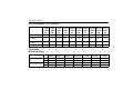
Table of Contents
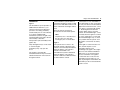
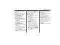
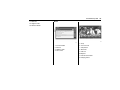
Introduction .........................................1
In brief .................................................3
Keys, doors and windows.................17
Seats, restraints................................45
Storage..............................................77
Instruments and controls ..................87
Lighting............................................125
Infotainment system........................135
Climate controls ..............................229
Driving and operating......................247
Vehicle care ....................................285
Service and maintenance ...............353
Technical data.................................365
Customer information .....................371
Memo
Introduction
Introduction
When this Owner’s Manual refers to
a repairer visit, we recommend your
Chevrolet Service Partner.
Introduction
All Chevrolet Service Partners
provide first-class service at
reasonable prices. Experienced
mechanics trained by Chevrolet work
according to specific Chevrolet
instructions.
Your vehicle is a designed
combination of advanced
technology, safety, environmental
friendliness and economy.
This Owner’s Manual provides you
with all the necessary information to
enable you to drive your vehicle
safely and efficiently.
The customer literature pack should
always be kept ready to hand in the
vehicle.
Make sure your passengers are
aware of the possible risk of accident
and injury which may result from
improper use of the vehicle.
Using this Manual
You must always comply with the
specific laws and regulations of the
country that you are in. These laws
may differ from the information in this
Owner’s Manual.
This manual describes all options
and features available for this
model. Certain descriptions,
including those for display and
menu functions, may not apply to
your vehicle due to model variant,
country specifications, special
equipment or accessories.
The "In brief" section will give you
an initial overview.
1
The table of contents at the
beginning of this manual and
within each chapter shows where
the information is located.
The index will enable you to
search for specific information.
The Owner's Manual uses the
factory engine designations. The
corresponding sales designations
can be found in the chapter
"Technical data".
Directional data, e.g. left or right,
or front or back, always relate to
the direction of travel.
The vehicle display screens may
not support your specific
language.
2
Introduction
Danger, Warnings and
Cautions
{Danger
Text marked ? Danger provides
information on risk of fatal injury.
Disregarding this information may
endanger life.
{Warning
Text marked ? Warning provides
information on risk of accident or
injury. Disregarding this
information may lead to injury.
Caution
Text marked Caution provides
information on possible damage to
the vehicle. Disregarding this
information may lead to vehicle
damage.
We wish you many hours of
pleasurable driving
Chevrolet
In brief
In brief
Initial drive information
3
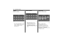
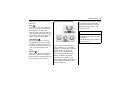
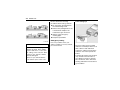
Seat adjustment
Seat positioning
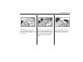
Unlocking the Vehicle
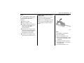
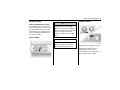
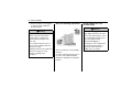
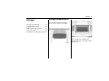
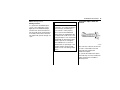
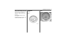
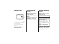
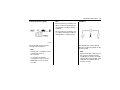
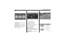
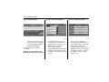
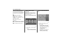
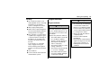
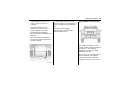
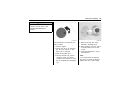
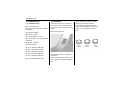
Radio remote control
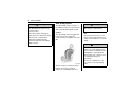
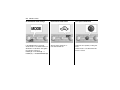
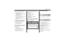
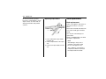
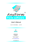
1968931
C11E2076A
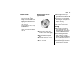
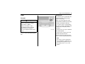
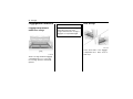
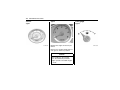
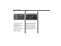
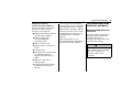
1. LOCK button
2. UNLOCK button
3. TALGATE WINDOW button
See Radio remote control on page
18.
See Central locking system on page
26.
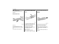
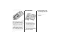
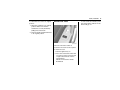
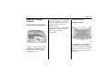
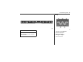
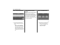
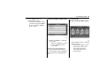
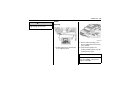
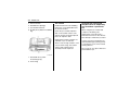
To move seat forward or backward,
pull the lever and slide seat to
desired position.
Release the handle and make sure
the seat is locked in place.
See Seat adjustment on page 48.
See Seat position on page 47.
4
In brief
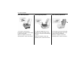
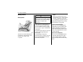
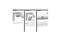
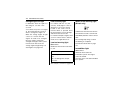
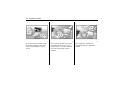
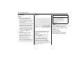
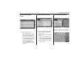
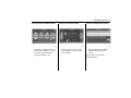
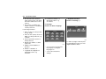
Seat backrests
Seat height
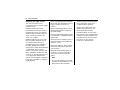
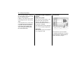
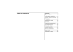
C11E2053A
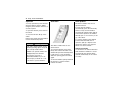
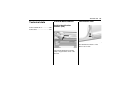
Pull lever, adjust inclination and
release lever. Allow the seat to
engage audibly.
Do not lean on seat when adjusting.
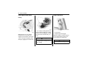
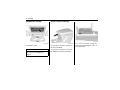
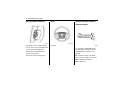
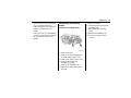
Seat lumbar support
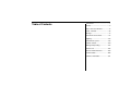
C11E2054A
Pumping the lever on the outside of
the seat cushion until the seat
cushion is adjusted to the desired
position.
To lower the seat cushion, push the
lever down several times.
To raise the seat cushion, pull the
lever up several times.
C11E2055A
To increase or decrease the driver's
seat lumbar support, move the lever
forward or rearward.
In brief
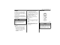
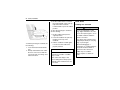
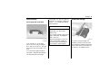
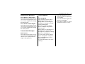
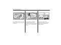
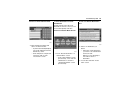
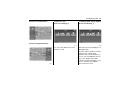
Head restraint adjustment
5
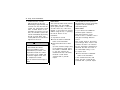
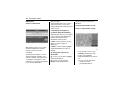
Safety Belt
Horizontal adjustment
Height adjustment
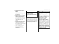
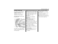
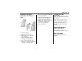
C11E1010A
C11E1015A
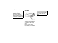
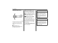
Pull the head restraint upwards.
To move down press the catch and
push the head restraint downwards.
See Head restraints on page 45.
Pull the head restraint forwards. To
move back pull the head restraint
forwards. Then it is moved
automatically backwards.
MD033
Withdraw belt from reel, guide it
untwisted across the body and
engage the latch plate in the buckle.
Tension the lap belt regularly whilst
driving by tugging the shoulder belt.
See Safety belts on page 58.
6
In brief
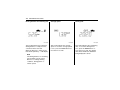
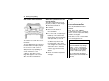
Mirror Adjustment
Steering Wheel Adjustment
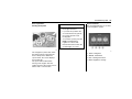
Exterior mirrors
Interior mirrors
2178629
C11E3008A
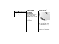
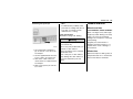
To reduce dazzle, pull the lever on
the underside of the mirror housing.
See Manual rearview mirror on page
38.
Select the mirror you want to adjust
by moving the selector switch to "L"
for LH mirror or to "R" for RH mirror.
See Remote control mirrors on page
36.
C11E3010A
Unlock lever, adjust steering wheel,
then engage lever and ensure it is
fully locked. Do not adjust steering
wheel unless vehicle is stationary.
In brief
7
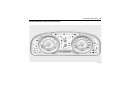
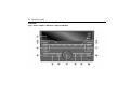
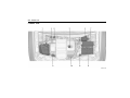
Instrument Panel Overview
LHD Vehicle
C3E1001A
8
In brief
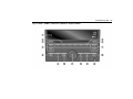
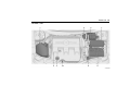
RHD Vehicle
C3E1002A
In brief
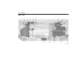
1. Air vents
2. Turn and lane / Exterior lamp
controls
3. Horn
4. Instrument cluster
5. Windshield wiper / Washer
19. Cigarette lighter
20. Audio system
21. Glove box
22. Front passenger safety belt
reminder lamp / Passenger
airbag OFF indicator
9
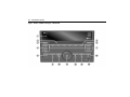
Exterior Lighting
6. Hazard warning flashers / ESC
OFF switch
7. Centre deposit box
8. DCS switch / Eco (stop/start)
switch or Park assist switch
9. Combination switch
10. Card holder
11. Coin storage
12. Hood release lever
13. Steering wheel audio controls
14. Cruise control / Climate control
buttons
15. Climate control systems
16. Shift lever
17. Electric parking brake (EPB)
switch
18. Eco switch
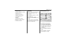
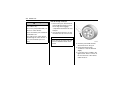
2238127
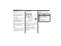
To turn the exterior lamps on or off,
turn the light switch knob. The light
switch has four positions as follows:
P(OFF): To turn off all lamps, turn
the knob to OFF position.
All lamps are off and return knob to
its original AUTO position.
10
In brief
AUTO: Exterior lamps and
instrument panel lamps are
automatically turned on or off
depending on external lighting
conditions.
Headlamp high/low-beam
changer
Hazard warning flashers
; : The tail lamps, number plate
lamps, and instrument panel lamps
are illuminated.
2 : The headlamps and all of the
above lamps are illuminated.
See Exterior lamp controls on page
125.
C11E2050A
C11E2071A
To switch from low to high beam,
push lever.
To switch to low beam, push lever
again or pull.
See Headlamp high/low-beam
changer on page 127.
See Flash-to-pass on page 128.
Operated with the | button.
See Hazard warning flashers on
page 129.
In brief
Turn and lane-change signals
Horn
11
Washer and Wiper Systems
Windshield wiper
2268202
lever up = right indicator
lever down = left indicator
See Turn and lane-change signals
on page 129.
C11E2039A
Press Y
2238054
To operate the windshield wipers,
turn the ignition ON and move the
windshield wiper / washer lever
upward.
HI: Continuous wipe, fast speed.
LO: Continuous wipe, slow speed.
INT: Intermittent operation.
OFF: System off.
12
In brief
MIST: Misting function.
Rear window wiper/washer
See Windshield wiper/washer on
page 88.
Wiper
See Rear window wiper/washer on
page 91.
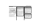
Washer
Windshield washer
2274836
C11E2006A
Pull lever.
See "Windshield washer" under
Windshield wiper/washer on page
88.
See Washer fluid on page 307.
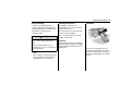
To operate the tailgate wiper, turn
the ignition ACC or ON and rotate
the end of the windscreen
wiper/washer lever upward.
The tailgate wiper operates in the
following three positions:
OFF: System off.
INT: Intermittent operation.
LO: Continuous wipe, slow speed.
C11E2007A
Press the button at the end of the
lever until the washers begin.
When you release the button, the
washers will stop, but the wipers will
continue to wipe for about three
times.
See Rear window wiper/washer on
page 91.
In brief
See Washer fluid on page 307.
Demisting and defrosting the
windows
Climate control
13
Transmission
Manual transmission
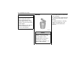
Heated rear window, heated
exterior mirrors
C11E4005A
2457824
Turn the air distribution knob to
DEFROST 5.
C3D2007A
Operated by pressing the = button.
See Heated mirrors on page 37.
See Heated rear window / windshield
wiper de-icer on page 41.
See "Defrosting windshield" under
Heating and ventilation system on
page 229.
See "Demisting windshield" under Air
conditioning system on page 232.
To change gears, fully depress the
clutch pedal, move the gearshift
lever into gear, and slowly release
the clutch.
To shift into reverse, press the button
on the back of the shift knob while
moving the shift lever into the
reverse position.
See Manual transmission on page
262.
14
In brief
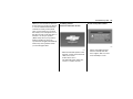
Automatic transmission
C12E9003A
Depress the brake pedal and push
release button to shift.
Shifts that require you to push the
release button are indicated by
arrows.
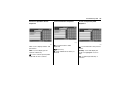
C11E3002A
C3D3004A
P (PARK): Locks the front wheels.
Select P only when the vehicle is
stationary and the parking brake is
applied.
R (REVERSE): Select R only when
the vehicle is stationary.
N (NEUTRAL): Neutral gear.
D: For all normal driving conditions.
Allows the transmission to shift into
all 6 forward gears.
+, -: Manual mode position.
MD173
MD174
Push the release button to shift.
Arrows indicate shifts that do not
require you to push the release
button.
Shift freely.
In brief
Getting Started
Check before starting off
15
Diesel engine: turn the key to
position ON for preheating until K
goes out.
Starting engine with the
ignition switch
Tire pressure and condition.
Turn the key to position START,
depressing the clutch pedal and
footbrake then release when
engine is running
Engine oil level and fluid levels.
All windows, mirrors, exterior
lighting and number plates are
free from dirt, snow and ice and
are operational.
Before restarting or to switch off the
engine, turn key back to LOCK.
Proper position of seats, safety
belts and mirrors.
Parking
Check brake function at low
speed, particularly if the brakes
are wet.
C11E3021A
Turn the key to position ACC,
move the steering wheel slightly
to release the steering wheel lock
Manual transmission: operate
clutch
Automatic transmission : Move
selector lever to P or N.
Do not accelerate
Do not park the vehicle on an
easily flammable surface. The
high temperature of the exhaust
system could ignite the surface.
Always apply parking brake
without pressing release button.
Apply as firmly as possible on
downhill or uphill slopes. Depress
the footbrake at the same time to
reduce operating force.
Switch off the engine and ignition.
Turn the steering wheel until the
steering wheel lock engages.
16
In brief
If the vehicle is on a level surface
or uphill slope, engage first gear
or P position before switching off
the ignition. On an uphill slope,
turn the front wheels away from
the kerb.
If the vehicle is on a downhill
slope, engage reverse gear
before switching off the ignition.
Turn the front wheels towards the
kerb.
Close windows.
Lock the vehicle.
Keys, doors and windows
Keys, doors and
windows
Keys and locks
17
Key with foldaway key section
Keys
Replacement keys
Keys and locks ..............................17
Doors .............................................28
Vehicle Security.............................30
Exterior Mirrors ..............................36
Interior Mirrors ...............................38
Windows ........................................39
Roof ...............................................43
The key number is specified on a
detachable tag.
The key number must be quoted
when ordering replacement keys as
it is a component of the immobiliser
system.
See "Lock" under Exterior care on
page 348.
C11E2075A
Press button to extend.
To fold the key, press the button and
fold the key manually.
18
Keys, doors and windows
Radio remote control
Hazard lamps will flash twice and
anti-theft system will be
deactivated.
In some countries, to unlock
driver’s door, press the UNLOCK
button once.
To unlock all doors, press the
UNLOCK button again within 3
seconds.
3. TAILGATE WINDOW button :
Releases the tailgate window
when pressed for about 1
second.
Used to operate:
Central locking system
Anti-theft alarm system
Tailgate window
C11E2076A
1. LOCK button: Locks all doors.
Hazard lamps will flash once and
the anti-theft system will be
activated.
2. UNLOCK button: Unlocks all
doors.
Note
When you press UNLOCK button
on the remote keyless entry
transmitter, instrument panel
lamps will come on automatically
and stay on for about 30 seconds
until the ignition switch is in the
ACC position.
The radio remote control has an
approximate range of about 6
metres(20 feet). This range can be
affected by outside influences.
Note
The hazard warning flashers confirm
operation.
LOCK, UNLOCK and TAILGATE
WINDOW buttons are not operated
while the key is in the ignition
switch.
Handle with care, protect from
moisture and high temperatures and
avoid unnecessary operation.
Keys, doors and windows
Fault
If the central locking system cannot
be operated with the radio remote
control, it may be due to the
following:
Range exceeded,
Battery voltage too low,
Frequent, repeated operation of
the remote control while not in
range, which will require
resynchronisation,
Overload of the central locking
system by operating at frequent
intervals, the power supply is
interrupted for a short time,
Interference from higher-power
radio waves from other sources.
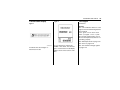
Radio remote control battery
replacement
19
Key with foldaway key section
Replace the battery as soon as the
range is noticeably diminished.
Batteries do not belong in household
waste. They must be disposed of at
an appropriate recycling collection
point.
2207429
Note
Use CR2032 (or equivalent)
replacement battery.
1. Open the transmitter cover.
2. Remove the used battery. Avoid
touching the circuit board to other
components.
3. Install the new battery. Be sure
the negative side (-) faces down
toward the base.
4. Close the transmitter cover.
20
Keys, doors and windows
5. Check the operation of the
transmitter with your vehicle.
Fixed key
Have the battery replaced by a
repairer.
Caution
Avoid dropping the transmitter.
Open & Start System
Do not place heavy objects on the
transmitter.
Keep the transmitter away from
water and direct sunlight. If the
transmitter gets wet, wipe it with a
soft cloth.
Avoid touching the flat surfaces of
the battery with your bare fingers.
Handling will shorten battery life.
Note
Used lithium batteries can harm
the environment.
Follow local recycling laws for
disposal.
Do not discard with household
waste.
Note
In order to keep the transmitter
working properly, follow these
guidelines:
C3D2013A
If the vehicle has the Keyless Access
System, the transmitter has a thin
button (A) near the bottom of the
transmitter used to remove the key.
Press the button (A) and pull the key
out. Do not pull the key out without
pressing the button (A).
The key, inside the transmitter, is
used for the driver door key cylinder
when the key fob is out of battery or it
is in emergency.
Keys, doors and windows
See your dealer if a new key is
needed.
C3D2010A
1. Q (Lock): Press once to lock the
all doors. The turn signal
indicators flash once or the horn
sounds once to confirm locking.
2. K (Unlock): Press once to unlock
all doors. The turn signal
indicators flash twice and
anti-theft system will be
deactivated. In some countries
according to vehicle
configuration, to unlock the
driver’s door, press the UNLOCK
button once. Then, to unlock all
the doors, press the UNLOCK
button again within 5 seconds.
The interior lamps may come on.
3. 8 (Tailgate glass): Press and
hold for about one second to
unlock the tailgate glass.
4. L (Vehicle Locator/Panic
Alarm): Press and hold for about
two seconds to locate the vehicle.
The turn signal lamps flash three
times and the horn sounds three
times.
21
Keyless Unlocking
J3D2002A
With the keyless access transmitter
within 1m, approach the front door
and push the button on the door
handle to unlock and open the door.
If the transmitter is recognized, the
door will unlock and open.
22
Keys, doors and windows
The ignition control knob can be
turned to four different positions.
Caution
The button on the door handle is
used only for keyless unlocking
function. When you leave vehicle,
lock all doors by pushing the lock
button in the keyless access
transmitter or be sure to check
activating the Keyless locking
function.
The keyless access transmitter
should be inside the vehicle when
trying to turn the ignition control
knob.
1: LOCK(Off)
2: ACC
3: ON
4: START
C3D3002A
• Manual transmission: Operate
clutch. Turn the ignition control
knob to the START position,
depressing the clutch pedal and
releasing the Electric Park Brake
switch with brake pedal pressed
when engine is running.
• Automatic transmission: Move
the shift lever to P (Park) or N
(Neutral). The engine will not
start in any other position. To
restart the engine when the
vehicle is already moving, use N
(Neutral) only.
If the vehicle has the keyless
access system, your foot must be
on the brake pedal to start the
engine.
• Diesel engine: Turn the ignition
control knob to the ON position
for preheating until K goes out.
Turn the ignition control knob to the
START position.
When the engine begins cranking, let
go of the ignition control knob, it will
return to the ON position.
If ignition control knob does not turn,
try pushing the knob in and turning
again.
If the transmitter is not in the vehicle
or something is interfering with the
transmitter, the Driver Information
Center (DIC) in the middle of the
cluster will display ELECTRONIC
KEY NOT DETECTED.
Keys, doors and windows
Keyless Locking
The doors lock after several seconds
if the ignition is off, all doors are
closed and at least one keyless
access transmitter has been
removed from the interior of the
vehicle.
At a self-service filling station, if
driver gets out of the vehicle with the
keyless access transmitter, all doors
including fuel filler door and tailgate
will be automatically locked after
several seconds. Press the button on
the door handle or push the unlock
button in the keyless access
transmitter to unlock all doors
including fuel filler door and tailgate
during fueling or when fueling is
done.
Programming Transmitters to
the Vehicle
23
Starting the Vehicle with a Low
Transmitter Battery
Only keyless access transmitters
programmed to the vehicle will work.
If a transmitter is lost or stolen, a
replacement can be purchased and
programmed through your dealer.
The vehicle can be reprogrammed
so that lost or stolen transmitters no
longer work.
C3D2017A
24
Keys, doors and windows
Battery Replacement
4. Insert the new battery, positive
side facing down. Replace with a
CR2032 or equivalent battery.
5. Snap the transmitter back
together.
6. Reinstall the key into the
transmitter.
C3D2016A
If the transmitter battery is weak, the
DIC in the middle of the cluster may
display ELECTRONIC KEY NOT
DETECTED when you try to start the
vehicle. To start the vehicle, place
the transmitter in the center console
storage area transmitter pocket with
the buttons facing up. Then, with the
vehicle in P (Park) or N (Neutral),
press the brake pedal and turn the
ignition control knob. Replace the
transmitter battery as soon as
possible.
2201493
1. Remove the key from the
transmitter by pressing the thin
button near the bottom of the
transmitter and pulling the key
out. Do not pull the key out
without pressing the button.
2. Separate the transmitter with a
flat, thin object inserted into the
slot on the side of the transmitter.
3. Remove the old battery.
Keys, doors and windows
Door locks
{Warning
The temperature inside the vehicle
can increase rapidly and reach
much higher levels than
temperature outside.
Do not leave unattended children
or pets in your vehicle.
25
Caution
Lock all doors and take the key
with you when you leave vehicle
unattended.
Unlocked vehicles invite theft.
Manual door locks
Death or serious injury can occur.
Children can operate electric
windows, other controls, or move
vehicle.
C3D2008A
Manually lock or unlock the driver’s
door by turning the key in the key
slot.
Do not leave key in vehicle with
children.
These actions can result in serious
injury or death.
C11E2031A
26
Keys, doors and windows
Central locking system
You can activate the central door
locking system from the driver's door.
This system allows you to lock and
unlock all the doors and tailgate from
the driver’s door, using either the key
or keyless remote (from outside) or
the door lock switch.(from inside)
Press the right part of the switch to
lock the doors.
To unlock the doors, press the left
part of the switch.
To open a door from the inside or
outside, pull the door handle.
Note
Grease should be applied to the
door check latch and hinge at
regular intervals or if a noise can
be heard when opening, closing
the door or during driving.
Central locking button
C11E2032A
To lock any door from the inside, pull
the door lock button.
The driver's door and the front
passenger's door can be opened
by pulling the door handle from the
inside even if the doors are locked
with the door lock button.
To unlock any door from the inside,
push the door lock button.
C11E2065A
You can also lock or unlock the
doors with the door lock switches on
the driver's door trim pad.
Keys, doors and windows
Deadlock
For further protection when leaving
the vehicle, you can deadlock the
doors if the vehicle has the additional
anti-theft system.
Deadlocking electronically jams all
the electric locks so that no door can
be opened, even if entry is gained by
breaking glass.
Insert the key in the driver door
lock and turn the key twice
continuously towards the rear of
the vehicle. That is, once to lock
the doors, then a second time to
engage the deadlock.
27
Safety locks
To disengage deadlock, press
UNLOCK button on the key. This
unlocks the doors.
Note
{Warning
Do not use deadlock if there are
people in the vehicle. The doors
cannot be unlocked from the
inside.
To engage deadlock, do one of the
following:
Press the LOCK button twice in
succession. Press the LOCK
button once to lock the vehicle,
and then press it again (within 3
seconds) to engage the
deadlock.
Deadlock function operates when
all doors and tailgate are closed.
Note
Disengaging the deadlock occurs
when unlocking the doors in the
normal way.
2058864
Caution
Do not pull the inside door handle
while the child security door lock is
set to LOCK position. To do so can
damage the inside door handle.
28
Keys, doors and windows
{Warning
Use the child security door locks
whenever children are occupying
the rear seats.
You can use a key or suitable
screwdriver.
To operate the child security door
lock, turn the child locks into
horizontal position.
To open a rear door when the child
security door lock is activated, open
the door from the outside.
To cancel the child security door
lock, turn the child locks into vertical
position.
Doors
{Warning
Tailgate
The tailgate can be locked or
unlocked by central door locking
system.
See Central locking system on page
26.
Make sure your hands and any other
body parts, as well as those of other
persons, are completely away from
the tailgate closure area.
Caution
When opening or closing the
tailgate, be sure to check it is free
from obstructions.
Driving the vehicle with the tailgate
or the tailgate window open can
allow exhaust gases to enter
passenger compartment.
Do not drive with tailgate open.
Exhaust gases are usually
poisonous and can cause injury or
death.
Keys, doors and windows
Caution
29
Tailgate window release
button
When unlocking the tailgate by the
tailgate release button, all doors
will also be unlocked. After closing
the tailgate, be sure to press the
lock button on the keyless access
transmitter for vehicle security.
C3D2015A
On vehicles with the Keyless Access
System, if the vehicle is locked, the
keyless access transmitter must be
within 1 m of the tailgate for it to be
recognized; the tailgate can then be
opened by the tailgate release button
above the license plate.
C11E2068A
You can open the tailgate window by
pressing the tailgate window release
button located in the driver’s door
trim.
The tailgate window can be also
opened by pressing the tailgate
window button on the remote key.
See Radio remote control on page
18.
30
Keys, doors and windows
Caution
Do not operate the tailgate window
release button while the vehicle is
moving.
Do not operate the vehicle with the
tailgate window open.
Vehicle Security
Anti-theft alarm system
Type 1
Security indicator
C11E2064A
After opening, hold the handle on the
tailgate window and lift it.
To close tailgate window, push it
down so it latches securely. It locks
automatically.
C11E2070A
Indicates the anti-theft system is
working.
The security indicator goes out when
doors are unlocked using the keyless
entry transmitter or key.
Keys, doors and windows
The security indicator comes on
when you lock the doors using the
keyless entry transmitter or key.
Door lock and anti-theft mode
Activation
1. Close all windows.
2. Turn the ignition key to LOCK
and remove the key.
3. Have all passengers exit the
vehicle.
4. Close all doors bonnet and
tailgate.
5. Press and release LOCK button
on the transmitter.
The LED on the transmitter will
flash.
All doors lock.
Hazard warning lamps flash
once.
Anti-theft mode is activated
after about 30 seconds.
If the key is inserted into
the ignition key hole, the
transmitter will not operate
the anti-theft system.
Note
The system can be activated even
if the windows are open. Close all
the windows and doors before
leaving the vehicle.
Note
If pressing the LOCK button on the
transmitter when all doors, bonnet
and tailgate are not completely
closed, the anti-theft system is in
the open state at this point and the
security indicator will flash quickly.
31
The anti-theft system transits to
the locked state when all doors,
bonnet and tailgate are
completely closed. The security
indicator will illuminate steady
when in the locked state. If the
LOCK button is pressed after all
doors, bonnet and tailgate have
been closed, the open state will
be bypassed and the system
will transit directly to the locked
state with the security indicator on
steady.
Note
The anti-theft system is activated if
the doors are locked manually
as well as the remote keyless
entry transmitter is used.
32
Keys, doors and windows
1. Confirm that the security
indicator flashes slowly after
illuminating for approximately 30
seconds from the time that the
system has entered the locked
state. If LOCK button on the
transmitter is pressed a second
time, the anti-theft system will
activate immediately, by passing
the 30 seconds delay. The
security indicator is located in the
right area of the clock.
{Warning
Do not lock the vehicle if anyone is
to be left inside the vehicle.
Never leave children or pets
unattended in your vehicle. The
temperature inside the vehicle
can increase more rapidly and
reach much higher levels than
the temperature outside.
This can result in serious injury or
death.
Horn sound
The system provides visual (exterior
lamps blink) sign and audible
(horns pulse) sound for about 30
seconds when any of the doors,
tailgate or the bonnet are opened
without using the key or pressing
the unlock button on the
transmitter.
To stop the horn sound:
Press the LOCK or UNLOCK
button on the transmitter.
Unlock the driver's door with a
key.
(In some countries, doing so may
not stop the horn sound. Press
the LOCK or UNLOCK button
to stop the sound) If the
unauthorised entry still exists,
the alarm sound will be
activated with a periodic
repeat.
If the system does not operate as
described above, have it checked by
a repairer. We recommend an
authorised repairer.
Siren sound
If your vehicle has additional
anti-theft system related to
Thatcham insurance, it has
intrusion sensor, inclination sensor
and glass breakage detection
sensor.
This system monitors the interior
space through these sensors and
activates the siren if an intrusion
into the passenger compartment is
detected, the tires are stolen or
the unintended towing occurs.
To stop the siren:
Press the LOCK or UNLOCK
button on the transmitter.
If the unauthorised entry still
exists, the siren sound will be
activated with a periodic repeat.
Keys, doors and windows
Note
Alarming will sound if a door is
opened by a key when anti theft
mode is activated.
Open the door using UNLOCK
button on the transmitter.
Note
Tap the key hole or heat the key if
the door does not open with
freezing key hole in cold weather.
33
{Warning
Do not use the transmitter to lock
the vehicle if anyone is to be left
inside.
The transmitter activates interior
protection, which will trigger the
siren if movement is detected
inside the vehicle.
Never leave children or pets alone
in your vehicle.
The temperature inside the vehicle
can increase more rapidly and
reach much higher levels than the
temperature outside.
This can result in serious injury or
death.
C11E2034R
If you want to turn off the additional
anti-theft system, press the button
located on the headliner. Anti-theft
off indicator o will come on.
When you activate the additional
anti-theft system by pressing the
button again, antitheft off indicator
will go out.
34
Keys, doors and windows
Door unlock and anti-theft
mode
Deactivation
1. Unlock the driver's door with a
key. Or,
2. Press and release UNLOCK
button on the transmitter.
The LED on the transmitter
will flash.
All the doors unlock.
Hazard warning lamps flash
twice.
Anti-theft mode is deactivated.
In some countries, unlocking the
driver door with a key may sound
alarm. Make sure to press the
UNLOCK button on the transmitter
to unlock doors.
Auto door relock
If the door is not opened or the
engine is not started within 30
seconds after disarming the system
using the transmitter, all the doors
are automatically locked and the
anti-theft mode is reactivated.
Type 2
Activation
To activate the system, press the
lock button on the keyless access
transmitter.
Anti-theft alarm system is activated
after about 30 seconds after keyless
locking function.
To activate the system, be sure to
have all doors, hood, and the tailgate
locked.
To avoid setting off the alarm when
opening the tailgate, press the
tailgate release button above the
license plate. The keyless access
transmitter must be within 1 m of the
tailgate.
Caution
On the keyless access system
vehicle, when unlocking the
tailgate by the tailgate release
button, all doors will also be
unlocked with the keyless access
transmitter within 1m(3ft) from the
rear bumper fascia. After closing
the tailgate, be sure to press the
lock button on the keyless access
transmitter for vehicle security.
Deactivation
To deactivate the system, do one of
the following:
• Press the unlock button on the
keyless access transmitter.
• With the keyless access
transmitter within 1m, approach
the door and push the button on
the door handle.
• Start the engine.
Keys, doors and windows
Immobiliser
Type 1
The immobiliser system provides an
additional theft deterrent to your
vehicle in which it is installed and
prevents it from being started by
unauthorised persons. The valid key
for a vehicle equipped with
immobiliser system is an ignition key
with integrated transponder, which is
electronically coded. The
transponder is placed invisibly in the
ignition key.
Only valid ignition keys can be used
to start the engine.
Invalid keys may only open the
doors.
The engine is automatically
immobilised after the key is turned to
LOCK and has been removed from
the ignition switch.
If the immobiliser system detects a
fault when the ignition switch is in ON
position, the immobiliser indicator will
flash or illuminate and engine will not
start.
Have the vehicle checked, we
recommend an authorised repairer.
Note
Tap the key slot or heat the key if
the door does not open with
freezing key slot in cold weather.
Type 2
The system does not have to be
manually armed or disarmed. The
vehicle is automatically immobilized
when the ignition control knob is
turned to LOCK/OFF. The
immobilization system is disarmed
when the ignition control knob is
turned to ON and a valid transmitter
is detected in the vehicle.
35
If the keyless access transmitter is
ever damaged, you may not be able
to start your vehicle. The immobilizer
light in the instrument cluster, comes
on if there is a problem with arming
or disarming the theft-deterrent
system. When trying to start the
vehicle, the immobilizer light comes
on briefly when the ignition is turned
on. If the engine does not start and
the immobilizer light stays on, there
is a problem with the system. Turn
the ignition control knob off and try
again.
If the ignition control knob does not
turn, and the keyless access
transmitter appears to be
undamaged, try again. If the engine
does not start and the immobilizer
light stays on, try another keyless
access transmitter. If the ignition
control knob does rotate, the first
transmitter may be faulty. Or, you
may try placing the transmitter in the
transmitter pocket located under the
center console.
36
Keys, doors and windows
If the ignition control knob still does
not rotate with the other transmitter,
or if the ignition control knob does
not rotate by placing the transmitter
in the transmitter pocket, the vehicle
needs service. See your dealer who
can service the theft-deterrent
system and have a new keyless
access transmitter programmed to
the vehicle.
Do not leave the key or device that
disarms or deactivates the theft
deterrent system in the vehicle.
Immobilizer does not lock the doors.
Always be sure to lock the vehicle to
activate anti-theft alarm system when
you leave the vehicle.
Exterior Mirrors
Remote control mirrors
Convex mirror
The convex exterior mirror reduces
blind spots. The shape of the mirror
makes objects appear smaller, which
will affect the abilty to estimate
distances.
2178629
Select the mirror you want to adjust
by moving the selector switch to "L"
for LH mirror or to "R" for RH mirror.
Adjust the selected mirror up, down,
left or right using the corresponding
edges of the mirror adjusting pad.
Keys, doors and windows
Folding mirrors
Manual folding(Russia only)
For pedestrian safety, the exterior
mirrors will swing out of their normal
mounting position if they are struck
with sufficient force. Reposition the
mirror by applying slight pressure to
the mirror housing.
{Warning
37
Heated mirrors
Always keep your mirrors properly
adjusted, and use them while
driving to increase your visibility of
objects and other vehicles around
you. Do not drive while either
outside rearview mirror is folded
back.
Power folding
Caution
Do not operate mirror continuous
while the engine is not running.
This will discharge the battery.
C3D2007A
Operated by pressing the + button.
Heating works with the engine
running and is switched off
automatically after a few minutes or
by pressing the button again.
38
Keys, doors and windows
Interior Mirrors
{Warning
Manual rearview mirror
Your view through the mirror may
lose some clarity when it is
adjusted for night vision.
Automatic dimming
rearview mirror
Electro-chromic mirror
Take special care with using your
inside rearview mirror when it is
adjusted for night vision.
Failure to ensure a clear rear view
while driving may result in a
collision causing damage to your
vehicle or other property, and/or
personal injury.
C11E3008A
To reduce dazzle, pull the lever on
the underside of the mirror housing.
C11E3009A
Your vehicle may be equipped with
Electro-Chromic Mirror(ECM), which
automatically reduces glare from
vehicles behind you providing
uniform light levels to your eyes.
Keys, doors and windows
To turn the ECM ON, press the
button on the mirror cover. The
indicator light will be illuminated. The
ignition switch must be in the ON
position.
To turn the ECM OFF, press the
button again.
Caution
There are two light sensors which
detect ambient light level and glare
from vehicles behind you.
Do not cover the sensors or hang
items on the EC mirror.
Doing so may limit the ECM
operation and you may have no
benefit from it.
39
Windows
Power windows
{Warning
Take care when operating the
power windows. Risk of injury,
particularly to children.
If there are children on the rear
seat, switch on the child safety
system for the power windows.
Keep a close watch on the
windows when closing them.
Ensure that nothing becomes
trapped in them as they move.
C11E2066A
Power windows can be operated with
ignition ON.
Operate the switch for the respective
window by pushing to open or pulling
to close.
40
Keys, doors and windows
Operation
Auto down
Auto up/down
You may operate the power windows
when the ignition switch is ON by
using the power window switches on
each door panel.
The driver’s window has an auto
up/down function.
To fully open the window
automatically, press the switch fully
down. To fully close the window
automatically, pull the switch fully up.
In automatic operation, the window
will fully open or close even if you let
go of the switch.
To open the window, press down on
the switch.
To close the window, lift up on the
switch.
Release the switch when the window
reaches the desired position.
{Warining
Body parts outside vehicle can be
struck by passing objects. Keep all
parts of body inside vehicle.
Children can operate and become
entrapped in power windows.
Do not leave your keys or
unattended children in your car.
Serious injury or death can occur
from misuse of power windows.
C11E2067A
The driver’s window has an auto
down function.
To lower the window, press down
firmly, then release the switch. The
window will open automatically until it
is fully open. To stop the window
while it is opening, press the switch
again.
To raise the window, pull up and hold
the switch. To stop the window,
release the switch.
To stop the window at the desired
position while the window is in
operation, pull up or depress and
release the switch to the opposite
direction of the movement.
Anti-pinch function
In case there is an obstacle detection
while the driver's window is closed
automatically, the window will be
opened automatically 11cm at least
for safety.
Keys, doors and windows
{Warining
Child safety system for rear
windows
41
Heated rear window /
windshield wiper de-icer
Anti-pinch function may not
operate after six consecutive times
operation. Do not operate the
window switch with no purpose.
C11E2069A
C3D2007A
Press switch v to deactivate rear
power windows.
To activate press v again.
Operated by pressing the + button.
Heating works with the engine
running and is switched off
automatically after a few minutes or
by pressing the button again.
42
Keys, doors and windows
Caution
Sun visors
{Warining
Do not place the sun visor in such
a manner that it obscures visibility
of the roadway, traffic or other
objects.
Do not use sharp instruments or
abrasive window cleaners on your
windshield or rear window.
Do not scratch or damage the
defroster wires when you clean or
work around the windshield or rear
window.
2326151
The sun visors can be folded down
or swivelled to the side to prevent
dazzling.
If the sun visors have integral
mirrors, the mirror covers should be
closed when driving.
Keys, doors and windows
43
Roof
Open/Close
Sunroof
To open the sunroof, pull weakly the
switch backward. It will manually
open as a first step.
{Warining
When you pull strongly the switch
backward then It will be automatically
and fully opened(Second Step).
Take care when operating the
sunroof. There is risk of injury,
particularly to children.
Keep a close watch on the
movable parts when operating
them. Ensure that nothing
becomes trapped in them as they
move.
Sunroof can be operated with ignition
ON.
To close the Sunroof, keep pushing
the switch forward or downward until
it will be fully closed(only,manual
operation)
C11D2018A
To tilt the sunroof up, press and hold
the switch upward.
To tilt the sunroof down, press and
hold the switch downward.
Please release the switch when the
sunroof reaches the desired position.
Note
The sunroof can be operated for
up to 10 minutes or until a door is
opened when the ignition key is in
the LOCK position or out of the
ignition.
44
Keys, doors and windows
Caution
Periodically inspect the guide rail
for dirt and clean if any dirt is
accumulated. If there is any dirt
around the rubber of the sunroof,
noise can be produced while
operating the sunroof.
Sunblind
The sunblind is operated manually.
Close or open the sunblind by
sliding.
When the sunroof is open, the
sunblind is always open.
{Warining
Body parts outside vehicle can be
struck by passing objects. Keep all
parts of body inside vehicle.
Serious injury or death can occur
from misuse of sunroof.
Seats, restraints
Seats, restraints
45
Head restraints
Head restraints
Head restraints ..............................45
Position
Front seats ....................................47
Safety belts....................................58
Airbag system................................61
Child restraints ..............................67
{Warning
Only drive with the head restraint
set to the proper position.
Removed or improperly adjusted
head restraints can result in
serious head and neck injuries in
case of a collision.
Make sure that the head restraint
readjusted before driving.
MD024
The middle of the head restraint
should be at eye level. If this is not
possible for extremely tall people, set
to highest position, and set to lowest
position for small people.
46
Seats, restraints
Height adjustment
Active head restraints
Horizontal adjustment
In the event of a rear-end impact, the
active head restraints at front seats
automatically tilt forwards. The head
is more effectively supported by the
head restraint and the risk of injuries
caused by hyperextension in the
cervical vertebrae area is reduced.
C11E1015A
Pull up the head restraints in order to
adjust the position upward. Push
down the head restraints while
pressing the release button in order
to adjust the position downward.
C11E1010A
To tilt the front head restraints,
1. Place it in its upright position by
pushing it forward fully and
releasing it.
2. Push the head restraint forward
carefully until it is adjusted to the
desired position.
Seats, restraints
Front seats
Seat position
{Warning
Only drive with the seat correctly
adjusted.
MD028
47
Sit with your buttocks as far back
against the backrest as possible.
Adjust the distance between the
seat and the pedals so that your
legs are slightly angled when
tromping the pedals. Slide the
passenger seat as far back as
possible.
Set the seat high enough to have
a clear field of vision on all sides
and on all display instruments.
There should be at least one
hand of clearance between your
head and the headlining. Your
thighs should rest lightly on the
seat without pressing into it.
Sit with your shoulders as far
back against the backrest as
possible. Set the backrest angle
so that you can easily reach the
steering wheel with your arms
slightly bent. Maintain contact
between your shoulders and the
backrest when turning the
steering wheel. Do not tilt the
backrest too far back. We
recommend a maximum angle of
approx. 25.
Adjust the head restraint. See
Head restraints on page 45.
Adjust the steering wheel. See
Steering wheel adjustment on
page 87.
Adjust the height of the safety
belt. See "Height adjustment"
under Three-point safety belts on
page 60.
48
Seats, restraints
Seat adjustment
Seat positioning
Seat backrests
{ Danger
Do not sit nearer than 25 cm(10in)
to the steering wheel, to permit
safe airbag deployment.
{Warning
Never adjust seats while driving as
they could move uncontrollably.
1968931
To move seat forward or backward,
pull the lever and slide seat to
desired position.
Release the lever and make sure the
seat is locked in place.
C11E2053A
Pull lever, adjust inclination and
release lever. Allow the seat to
engage audibly.
Note
Do not lean on seat when
adjusting.
Seats, restraints
Seat height
Power seat adjustment
(Driver’s seat only)
Seat lumbar support
{Warning
Do not adjust the driver's seat
while the vehicle is moving.
Driver could lose control of the
vehicle and injury or property
damage could result.
C11E2054A
Pumping the lever on the outside of
the seat cushion until the seat
cushion is adjusted to the desired
position.
To lower the seat cushion, push the
lever down several times.
To raise the seat cushion, pull the
lever up several times.
C11E2055A
To increase or decrease the driver's
seat lumbar support, move the lever
forward or rearward.
49
50
Seats, restraints
Seat slide adjustment
Seat height adjustment
C11E1011A
To move the seat forward or
backward, move and hold the switch
forward or backward.
When the seatback reaches the
desired position, release the switch.
Seat reclining adjustment
C11E1012A
To adjust the height of the front or
rear part of the seat cushion, push
the front or rear part of the switch up
or down.
When the seatback reaches the
desired position, release the switch.
C11E1013A
To tilt seatback forward or backward,
move and hold the upper part of the
switch forward or backward.
When the seatback reaches the
desired position, release the switch.
Seats, restraints
Heated front seats
Caution
51
Folding seatback
Passenger’s seat folding
Prolonged use of the highest
setting for people with sensitive
skin is not recommended.
Caution
If you fold the seatback forward to
carry longer objects, such as skis,
be sure any such cargo is not near
an airbag.
C11E2038A
The seat heater switches are located
below the centre console box. To
warm the seat:
1. Turn the ignition key on.
2. Press the seat heater switch that
you want to warm. Indicator in the
button will be illuminated.
To turn off the seat heater, press the
switch again. Indicator in the button
will go out.
In a crash, an inflating airbag might
force that object toward a person.
This could cause severe injury or
even death. Secure object away
from the area in which an airbag
would inflate.
Caution
Things you put on this seatback
can strike and injure people in a
sudden stop or turn, or in a crash.
Remove or secure all items before
driving.
52
Seats, restraints
3. Lift the recliner lever, located on
the outboard side of the seat, up
fully and fold the seatback
forward until it stops in the folded
position.
To raise the passenger’s seatback,
do the following:
To fold the passenger's seatback, do
the following:
1. Lower the head restraint all the
way.
2. Pull up and hold the lever under
the front of the seat to slide the
seat as far back as it will go and
release the lever.
1. Lift the seatback and push to
original position.
2. Latch the seatback into place by
pushing on the top of the
seatback.
3. Pull the seatback forward again
to make sure the seatback is
properly latched.
Caution
If the seatback is not locked, it
could move forward in a sudden
stop or crash.
That could cause injury to the
person sitting there. Always push
and pull on the seatback to be sure
it is locked.
Rear seats
Folding rear seatback
{Warning
Do not stack luggage or other
cargo higher than the front seats.
Do not allow passengers to sit on
the folded seatbacks while the
vehicle is in motion.
Your vehicle has separate areas
designed specifically for carrying
cargo or passengers.
Unrestrained luggage or
passengers on a folded seatback
can be thrown about within or
ejected from the vehicle in a
sudden stop or accident.
Serious injuries or death can
result.
Seats, restraints
53
Caution
Folding a rear seat with the safety
belts still fastened may cause
damage to the seat or the safety
belts. Always unbuckle the safety
belts and return them to their
normal stowed position before
folding a rear seat.
C11E1019A
To fold down the rear seatbacks
separately:
1. Ensure all three of the safety
belts are unbuckled and the front
seatbacks are not reclined.
2. Push the head restraints fully
down.
3. Lift the lever located on the top of
the seatback to release the
seatback.
4. Fold the rear seatback forward
and down.
To return a rear seatback to its
original position:
1. Hook the safety belts to the
retaining guide to make sure the
safety belts are not pinched.
2. Lift the rear seatback and push to
original position.
3. Unhook the safety belts from the
retaining guide.
4. Latch the seatback into place by
pushing on the top of the
seatback.
54
Seats, restraints
5. Pull the seatback forward again
to make sure the seatback is
properly latched.
Rear seat reclining adjustment
{Warning
{Warning
Do not stack luggage or other
cargo higher than the front seats.
Ensure that the rear seatbacks are
all the way back and locked in
position before operating the
vehicle with passengers in the
back seat.
Do not pull the release levers on
the top of the seatback while the
vehicle is moving.
Pulling the release levers while the
vehicle is moving can cause
injuries or damage to the
occupants.
Double folding rear seat
(7 seater only)
Do not allow passengers to sit on
rear compartment when the rear
seats are folded forward.
C11E1018A
The rear seatbacks can be partially
reclined.
To tilt the seatbacks, lift the lever on
top of the rear seatback until the
seatback is adjusted to the desired
position.
Unrestrained luggage or
passengers in rear compartment
can be thrown about within or
ejected from the vehicle in a
sudden stop or accident.
Seats, restraints
55
{Warning
Folding a rear seat with the safety
belts still fastened may cause
damage to the seat or the safety
belts.
Always unbuckle the safety belts
and return them to their normal
stowed position before folding a
rear seat.
When double folding or unfolding,
make sure the safety belt buckles
are not pinched by the seat.
Serious injuries or death can
result.
C11E1004A
For third row seating entry or exit, do
the following:
1. Ensure all three of the safety
belts are unbuckled and the front
seatbacks are not reclined.
2. Push the head restraints fully
down.
3. Pull the lever forward on the
outside of the seatback and fold
the seatback.
C11E1005A
4. The seat will tumble forward
automatically and air-pressurised
support rods will hold the seats
folded.
To return the rear seat to its original
position:
1. Hook the safety belts to the
retaining guide to make sure the
safety belts are not pinched.
2. Guide the rear seat cushion
down.
56
Seats, restraints
Folding the third row seat
3. Lock the rear seat cushion on the
floor.
Make sure that the rear seat
cushion is securely latched by
pulling it up and down.
4. Return the rear seatback to its
original position. Make sure that
the seatback is securely latched
by pulling it back and forth.
5. Unhook the safety belts from the
retaining guide.
C11E1017A
{Warning
C11E1006A
Do not place the legs or other body
parts on the floor under rear seat
cushion when guiding the rear seat
cushion down.
Serious injuries can result.
Caution
Do not pull the lever when the
seatback is folded. This operation
can cause damage to the lever or
related parts.
To fold down the third row seatbacks:
1. Ensure the safety belts are
unbuckled.
2. Lift the lever on the back of the
each seatback.
3. Push the seatback forward and
fold the seatback.
Seats, restraints
To return the rear seat to its original
position:
Heated rear seats
57
To turn off the seat heater, press
the switch again. Indicator in the
button will go out.
1. Raise the seatback to its original
position. Make sure that the
seatback is securely latched by
pulling it back and forth.
2. Push the head restraint backward
to its original position.
C3D2009A
The rear seat heater switch is
located on the each rear door panel.
To warm the seat:
1. Turn the ignition key on.
2. Press the seat heater switch that
you want to warm to heat the left
or right outboard seat cushion
and seatback.
Indicator in the button will be
illuminated.
58
Seats, restraints
Safety belts
{Warning
Safety belts
Fasten safety belt before each trip.
In the event of an accident, people
not wearing safety belts endanger
their fellow occupants and
themselves.
Safety belts are only designed for
use by one person at a time. They
are not suitable for people younger
than 12 years of age or smaller than
150 cm(5 ft).
MD033
The belts are locked during heavy
acceleration or deceleration of the
vehicle for the safety of the
occupants.
Periodically check all parts of the belt
system for damage and proper
functionality.
Have damaged components
replaced. After an accident, have the
belts and triggered belt tensioners
replaced by a repairer.
Note
Make sure that the belts are not
damaged by shoes or sharp-edged
objects or trapped. Prevent dirt
from getting into the belt retractors.
Safety belt reminder >. See Safety
belt reminders on page 106.
Front seat occupants
Each front seat is equipped with
adjustable seat and seatback with
height-adjustable head restraint,
three point lap-and-shoulder safety
belts, and a supplemental restraint
system (air bag).
Rear seat occupants
The rear seat is equipped with two
outboard seating positions and a
centre seating position featuring
three-point lap-and-shoulder safety
belts.
Seats, restraints
Each outboard seating positions are
equipped with child restraint lower
anchors and the top tether anchors
located on the back of the rear
seatback.
Belt tensioners
Note
In the event of a head-on or side or
rear-end collision of a certain
severity, the front safety belts are
tightened.
Do not affix or install accessories
or other objects that may interfere
with the operation of the belt
tensioners.
See Child Restraint Installation
Locations on page 69.
Third row seat occupants
The third row seat is equipped with
two seating positions featuring
three-point lap-and-shoulder safety
belts.
{Warning
Incorrect handling (e.g. removal or
fitting of belts or belt buckles) can
trigger the belt tensioners with risk
of injury.
Deployment of the belt tensioners is
Belt force limiters
In the front seats, stress on the body
is reduced by the gradual release of
the belt during a collision.
59
indicated by illumination of control
indicator 9.
See Airbag and safety belt tensioner
light on page 106.
Triggered belt tensioners must be
replaced by a repairer. Belt
tensioners can only be triggered
once.
Do not make any modifications to
belt tensioner components as this
will invalidate the vehicle type
approval.
60
Seats, restraints
Three-point safety belts
Height adjustment
Fitting
MD036
MD035
Withdraw belt from reel, guide it
untwisted across the body and
engage the latch plate in the buckle.
Tension the lap belt regularly while
driving by tugging the shoulder belt.
Loose or bulky clothing prevents the
belt from fitting snugly. Do not place
objects such as handbags or mobile
phones between the belt and your
body.
{Warning
The belt must not rest against hard
or fragile objects in the pockets of
your clothing.
C11E2059A
1. Press button.
2. Adjust height and engage.
Adjust the height so that the belt lies
across the shoulder. It must not lie
across the throat or upper arm.
{Warning
Do not adjust while driving.
Seats, restraints
Safety belt use during
pregnancy
Removing
61
Airbag system
Airbag system
{Warning
The belt must be positioned as low
as possible across the pelvis to
prevent pressure on the abdomen.
Safety belts work for everyone,
including pregnant women.
MD038
To release belt, press red button on
belt buckle.
Like all occupants, pregnant women
are more likely to be seriously injured
if they do not wear safety belts.
In addition, when a safety belt is
worn properly, it is more likely that
the unborn child will be safe in a
crash.
To provide maximum protection, a
pregnant woman should wear a
three-point safety belt.
She should wear the lap portion of
the belt as low as possible
throughout her pregnancy.
The airbag system consists of a
number of individual systems.
When triggered the airbags inflate
within milliseconds. They also deflate
so quickly that it is often unnoticeable
during the collision.
62
Seats, restraints
{Warning
If handled improperly the airbag
systems can be triggered in an
explosive manner.
The driver should sit back as far as
possible while still maintaining
control of the vehicle. If you are
sitting too close to the airbag, it can
cause death or serious injury when
it inflates.
For maximum safety protection in
all types of crashes, all occupants
including the driver should always
wear their safety belts to minimize
the risk of severe injury or death in
the event of a crash. Do not sit or
lean unnecessarily close to the
airbag while the vehicle is in
motion.
The airbag may cause facial or
body scratch, injury by broken
glasses or getting a burn by
explosion while airbag is deployed.
Note
The airbag systems and belt
tensioner control electronics are
located in the central console area.
Do not put any magnetic objects in
this area.
When an air bag deploys, there
may be a loud noise and smoke.
These conditions are normal and
are not dangerous but in case it
may stimulate skin of the
passenger. If the stimulation is
continued, contact a doctor.
Do not stick anything on the airbag
covers and do not cover them with
other materials.
{Danger
Each airbag is triggered only once.
Have deployed airbags replaced
by a repairer.
Never allow children or infants and
pregnant women and the old and
the weak sit in the front passenger
seats fitted with airbags.
Do not make any modifications to
the airbag system as this will
invalidate the vehicle type
approval.
In the event of airbag deployment
have the steering wheel, the
instrument panel, all panelling
parts, the door seals, the handles
and the seats removed by a
repairer.
Furthermore, do not drive with a
baby seat fitted thereon. In case of
an accident, the impact from the
inflated airbag can cause facial
injury or death.
Seats, restraints
Caution
If the vehicle is impacted by bumps
or objects on unpaved roads or
sidewalks, the air bag may inflate.
Drive slowly on the surfaces not
designed for vehicle traffic to
prevent unintended air bag
deployment.
63
Front airbag system
The front airbag system consists of
one airbag in the steering wheel and
one in the instrument panel on the
passenger side. These can be
identified by the word AIRBAG.
Control indicator 9 for airbag
systems.
MD039
See Airbag and safety belt tensioner
light on page 106.
The forward movement of the front
seat occupants is retarded, thereby
considerably reducing the risk of
injury to the upper body and head.
C11E1009A
The front airbag system is triggered
in the event of an accident of a
certain severity in the depicted area.
The ignition must be ON.
64
Seats, restraints
{Warning
Optimum protection is only
provided when the seat is in the
proper position.
See Seat position on page 47.
Keep the area in which the airbag
inflates clear of obstructions.
Wear the seat belt properly
fastened. Only then the airbag is
able to protect.
Side airbag system
{Warning
The side airbag system consists of
an airbag in each front seat backrest.
This can be identified by the word
AIRBAG.
The side airbag system is triggered
in the event of an accident of a
certain severity. The ignition must be
ON.
Keep the area in which the airbag
inflates clear of obstructions.
Note
Only use protective seat covers
that have been approved for your
vehicle. Be careful not to cover the
airbags.
{Warning
Children who are seated in close
proximity to a side airbag may be
at risk of serious or fatal injury if the
airbag deploys, especially if the
child's head, neck, or chest is close
to the airbag at the time of
deployment.
2235845
The risk of injury to the thorax and
pelvis in the event of a side-on
collision is considerably reduced.
Never let your child lean on the
door or close to the side airbag
module.
Seats, restraints
Curtain airbag system
65
{Warning
Keep the area in which the airbag
inflates clear of obstructions.
The hooks on the handles in the
roof frame are only suitable for
hanging up light articles of clothing,
without coat hangers. Do not keep
any items in these clothes.
2235846
TDL092A
The curtain airbag system consists of
an airbag in the roof frame on each
side. This can be identified by the
word AIRBAG on the roof pillars.
The curtain airbag system is
triggered in the event of an accident
of a certain severity. The ignition
must be ON.
The risk of injury to the head in the
event of a side impact is
considerably reduced.
66
Seats, restraints
Airbag on-off switch
{Warning
Front airbag system for the front
passenger seat have to be
deactivated if a child restraint system
is to be fitted on this seat. The curtain
airbag system, the belt tensioners
and all driver airbag systems will
remain active.
Deactivate front passenger airbag
system when the front passenger
seat is occupied by a child.
Activate front passenger airbag
system when an adult is on the
front passenger seat.
Use the ignition key to choose the
position:
U = front passenger airbags are
deactivated and will not inflate in the
event of a collision. Control indicator
+ illuminates continuously. A child
restraint system can be installed in
accordance with the chart.
TEL014A
Front passenger airbag system can
be deactivated via a lock on the side
of the instrument panel, visible when
the front passenger door is open.
V = front passenger airbags are
activated. No child restraint systems
can be installed.
C11E2056A
As long as the control indicator + is
not illuminated, the airbag systems
for the front passenger seat will
inflate in the event of a collision.
Change status only when the vehicle
is stopped with the ignition off.
Status remains until the next change.
Control indicator for airbag
deactivation.
See Airbag on-off light on page 107.
Seats, restraints
Child restraints
67
{Warning
Child restraint systems
WARNING–EXTREME HAZARD
We recommend the GM child
restraint system which is tailored
specifically to the vehicle.
Do not use a rearward facing child
restraint on a seat protected by an
airbag in front of it.
When a child restraint system is
being used, pay attention to the
following usage and installation
instructions and also those supplied
with the child restraint system.
The child could be seriously injured
if the airbag inflates, as the child's
head would be very close to the
inflating airbag.
Always comply with local or national
regulations. In some countries, the
use of child restraint systems is
forbidden on certain seats.
GC3E3001A
{Warning
NEVER use a rearward facing
child restraint on a seat protected
by an ACTIVE AIRBAG in front of
it, DEATH or SERIOUS INJURY to
the CHILD can occur.
{Warning
When using a child restraint
system on the front passenger
seat, the airbag systems for the
front passenger seat must be
deactivated; if not, the triggering of
the airbags poses a risk of fatal
injury to the child.
This is especially the case if
rearfacing child restraint systems
are used on the front passenger
seat.
68
Seats, restraints
Selecting the right system
The rear seats are the most
convenient location to fasten a child
restraint system.
Never carry a child while travelling in
the vehicle. The child will become too
heavy to hold in the event of a
collision.
Children should travel facing
rearwards in the vehicle as long as
possible. This makes sure that the
child's backbone, which is still very
weak, is under less strain in the
event of an accident.
When transporting children, use the
child restraint systems suitable for
the child's weight.
Children under the age of 12 years
that are smaller than 150 cm (5 ft)
are only allowed to travel in a
restraint system that is suitable for
the child. Suitable are restraint
systems that comply with ECE 44-03
or ECE 44-04. Since a proper
position of the belt is rarely possible
with a child that is smaller than 150
cm (5 ft), we strongly advise the use
of an appropriate child restraint
system, even though this might, due
to the age of the child, no longer be
legally binding.
Ensure that the mounting location of
the child restraint system within the
vehicle is correct.
Ensure that the child restraint system
to be installed is compatible with the
vehicle type.
Only allow children to enter and exit
the vehicle at the side facing away
from the traffic.
When the child restraint system is
not in use, secure the seat with a
safety belt or remove it from the
vehicle.
Note
Do not stick anything on the child
restraint systems and do not cover
them with any other materials.
A child restraint system which has
been subjected to stress in an
accident must be replaced.
Please ensure that infants and
children are seated in the rear
seats using child restraints.
Until the children can use safety
belts, please select a child restraint
suitable for its age and make sure
the child wears it. Please see the
instructions on the relevant
products for child restraints.
Seats, restraints
69
Child Restraint Installation Locations
Permissible options for fitting a child restraint system
On front passenger seat
Weight class
Group 0
up to 10 kg
Group 0+
Group I
up to 13 kg
9 to 18 kg
Group II
15 to 25 kg
Group III
22 to 36 kg
activated
airbag
deactivated
airbag
X
X
X
X
X
U1
U1
U1
X
X
On outboard
seats in the
second row
On centre
seat in the
second row
On the seats
in the third
row
U+
U+
U+
U
U
X
X
X
X
X
X
X
X
X
X
1: Only if front passenger seat airbag systems are deactivated. If the child restraint system is being secured using a
three-point safety belt, adjust the seat backrest angle to the most forward position and ensure that vehicle safety belt
runs forwards from the upper anchorage point.
+: Seat available with ISOFIX and Top-Tether mounting brackets.
U: Universal suitability in conjunction with three-point safety belt.
X: No child restraint system permitted in this weight class.
70
Seats, restraints
Permissible options for fitting an ISOFIX child restraint system
Weight class
Group 0
Group 0+
Group I
up to 10 kg
up to 13 kg
9 to 18 kg
Size class
Fixture
On front
passenger
seat
On outboard
seats in the
second row
On centre seat
in the second
row
On the seats
in the third
row
E
ISO/R1
X
IL
X
X
E
ISO/R1
X
IL
X
X
D
ISO/R2
X
IL
X
X
C
ISO/R3
X
IL
X
X
D
ISO/R2
X
IL
X
X
C
ISO/R3
X
IL
X
X
B
ISO/F2
X
IL, IUF
X
X
B1
ISO/F2X
X
IL, IUF
X
X
A
ISO/F3
X
IL, IUF
X
X
IL: Suitable for particular ISOFIX restraint systems of the 'specific-vehicle', 'restricted' or 'semi-universal' categories.
The ISOFIX restraint system must be approved for the specific vehicle type.
IUF: Suitable for ISOFIX forward-facing child restraint systems of universal category approved for use in this mass
group.
X: No ISOFIX child restraint system approved in this weight class.
Seats, restraints
ISOFIX size class and seat device
A - ISO/F3: Forward-facing child restraint system for children of maximum size in the weight class 9 to 18 kg.
B - ISO/F2: Forward-facing child restraint system for smaller children in the weight class 9 to 18 kg.
B1 - ISO/F2X: Forward-facing child restraint system for smaller children in the weight class 9 to 18 kg.
C - ISO/R3: Rear-facing child restraint system for children of maximum size in the weight class up to 13 kg.
D - ISO/R2: Rear-facing child restraint system for smaller children in the weight class up to 13 kg.
E - ISO/R1: Rear-facing child restraint system for young children in the weight class up to 13 kg.
71
72
Seats, restraints
Isofix child restraint
systems
We now equip your vehicle with
ISOFIX low anchorages at the two
rear outboard seating positions and
with top tether anchorages in the rear
seat backward allowing child
restraints to be attached to the rear
seats.
To install a child restraint which
comes equipped with ISOFIX low
and top tether anchorage
attachments, follow the instructions
supplied with your child restraint.
C11E1001A
In the past, child restraints have
been attached to a vehicle's seat by
safety belts.
Please take the time to carefully read
and follow all of the instructions on
the following pages and the
instructions supplied with your child
restraint.
If you have questions, or any doubts
whether you have installed your child
restraint properly, contact the child
restraint manufacturer. If you are still
having trouble installing the child
restraint in your vehicle, we
recommend that you consult an
authorised repairer.
Installation of ISOFIX child restraint
systems
1. Select one of the rear outboard
seating positions for installation
of the child restraint.
Your child’s safety depends on it!
As a result, child restraints were
often installed incorrectly or too
loosely to adequately protect your
child.
C11E1003A
Seats, restraints
2. Locate the two lower anchor
positions.
The location of each lower
anchor is identified with a circular
marking on the lower edge of the
rear seatback.
3. Make sure there are no foreign
objects around lower anchors,
including safety belt buckles or
safety belts. Foreign objects can
interfere with the proper latching
of the child restraint to the
anchors.
4. Place the child restraint on the
seat over the two lower anchors
and attach it to the anchors
following the instructions supplied
with the child restraint.
5. Adjust and tighten the child
restraint according to the
instructions supplied with the
child restraint.
Caution
Unused child restraint system
could move forward.
Remove child restraint system if
not in use, or secure it with safety
belt.
Note
Since a safety belt or child restraint
system can become very hot if it is
left in a closed vehicle, be sure and
check the seat cover and buckles
before placing a child there.
73
{Warning
Use all ISOFIX low and top tether
anchorages for their designed
purpose only.
ISOFIX low and top tether
anchorages are designed only to
hold child restraints which come
equipped with low and top
anchorage attachments.
Do not use ISOFIX low and top
tether anchorages to hold adult
safety belts, harnesses, or other
items of equipment in your vehicle.
Using ISOFIX low and top tether
anchorages to hold adult safety
belts, harnesses, or other items or
equipment in your vehicle will not
provide adequate protection in the
case of a collision and could result
in injuries or even death.
74
Seats, restraints
{Warning
Caution
Child restraint system placed in the
front seat could cause serious
injury or death.
Full size rear facing child seats
may not be suitable for installation.
Contact your retailer for
information regarding suitable child
restraint systems.
Never install a rear-facing child
restraint in the front seat of a
vehicle equipped with a front
passenger air bag.
A child in a rear-facing child
restraint installed in the front seat
can be seriously injured if the front
passenger air bag inflates.
Secure a rear-facing child restraint
in the rear seat.
A front-facing child restraint should
be secured in the rear seat
whenever possible.
If installed in the front passenger
seat, adjust the seat as far back as
it will go.
Top-tether child restraint
systems
Installation of child restraints with
ISOFIX low and top tether
anchorage attachments.
2235843
To access the top tether anchor
points, do the following:
1. Remove the foreign objects
around the top tether anchor.
Remove the luggage
compartment cover.
Seats, restraints
2. Attach the clip on the child
restraint's tether strap to the top
tether anchor, making sure to
remove any twists in the tether
strap.
If the position you are using has
an adjustable head restraint and
you are using a dual tether, route
the tether around the head
restraint.
If the position you are using has
an adjustable head restraint and
you are using a single tether,
raise the head restraint and route
the tether under the head
restraint and in between the head
restraint posts.
3. Tighten the child restraint's tether
strap according to the
instructions supplied with the
child restraint.
4. Push and pull on the child
restraint after installation to be
sure the child restraint is secure.
C11E1008A
{Warning
Make sure the clip on the child
restraint's tether strap is properly
attached to the top tether
anchorage.
Incorrect attachment could render
the tether strap and top tether
anchorage ineffective.
75
Memo
Storage
Storage
77
Storage compartments
Instrument panel storage
Storage compartments ..................77
Luggage/load locations .................82
Additional Storage Features ..........83
Roof rack system...........................84
Information on loading the vehicle.85
C11E2024A
C11E2025A
The storages are located in the
instrument panel. It is used for small
articles, etc.
78
Storage
Card holder
Glovebox
Coin storage
C11E2077A
You can use the card holder by
inserting a card into slot.
C11E2023A
To open the coin storage, pull the
handle on the coin storage door
toward you.
To close the coin storage, firmly
push the coin storage door shut.
C11D2019A
Open the glove box by pulling the
bottom of the handle upward and
the glove box lamp will be turned
on. Close the glove box with a
firm push and the glove box lamp
will be turned off.
Storage
Cupholders
{Warning
Do not place uncovered cups of
hot liquid in the cup holder while
the vehicle is in motion. If the hot
liquid spills, you burn yourself.
Such a burn to the driver could
lead to loss of control of the
vehicle.
The inner partition can be removed if
you want to store larger items.
After taking inner partition off,
keep it in the left side groove of
the glove box.
{Warning
To reduce the risk of injury in an
accident or a sudden stop, always
keep the glovebox door closed
while driving.
C11D2026A
The cup holders are located in
the center console and in the
second row seat armrest.
To use the rear cup holder, push
the button above the cup holder.
The rear cup holder will pop out
automatically.
To reduce the risk of personal
injury in the event of sudden stop
or collision, do not place
uncovered or unsecured bottles,
glasses, cans, etc., in the cup
holder while the vehicle is in
motion.
79
80
Storage
Sunglasses storage
Center console storage
C11E2028A
C11E2022A
Fold down to open.
Caution
Do not use for storing heavy
objects.
C11D2021A
To open the console box, pull up on
the lever and lift lid.
To close the console box, lower the
lid and push it down until it latches.
You can use another storage by
pressing and pushing the lever on
the cup holders.
Storage
Roof paneling
Assist grip with coat hook
Passengers can use the grips for
assistance in entering / exiting the
vehicle, or for hand-holds during
spirited driving.
81
Underseat storage
Caution
Hanging items on your vehicle's
assist grips can obstruct the
driver’s view.
Do not hang anything on the assist
grips, unless they are equipped
with a coat hook.
C11E2035A
Your vehicle has assist grips
above the front seat passenger’s
door and the rear doors. The grip
above each rear door includes coat
hook.
To use the assist grips, pull down
and hold it. The grips will swing up
automatically when releasing it.
Obstructing the driver’s view can
lead to an accident resulting in
personal injuries and damage to
your vehicle or other property.
C11E2030A
To use the front passenger seat
undertray, pull up on the end of the
tray and pull it toward the instrument
panel. Push the tray toward the seat
to return it to its original position.
82
Storage
Luggage/load locations
Luggage compartment
Under floor storage
Caution
Rear storage
Do not allow items in the storage to
extend above the top of the
storage. Otherwise, the storage or
luggage floor may be damaged.
C11E2045A
C11E2044A
There is storage under the luggage
compartment floor. To access the
floor storage, pull floor mat handle
upward.
In the both sides of the luggage
compartment floor, there are floor
side trays.
Storage
Additional Storage
Features
Load Compartment Cover
To operate the cover, pull the handle
of the cover toward you and then
insert the retainer into the slot
located on both sides of the
tailgate openings.
83
Convenience net
Luggage floor net
To remove the cover, release the
handle after pulling it toward you a
little. The cover retracts
automatically.
2207499
C11E2042A
Luggage or other cargo placed in
the luggage compartment can be
hidden from view by a luggage
compartment cover.
The luggage floor net can help keep
small loads from moving during
sharp turns or quick starts and stops.
Attach the four net hooks in the
metal rings on the each corner of
the floor.
84
Storage
Luggage holder net
Caution
The luggage holding net is
designed for small loads.
Do not carry heavy objects in your
luggage holding net.
C11E2043A
You can carry small loads with
your optional luggage holding net.
To install the net, hang each loop
in the upper corner of the net to
both anchors of the back panel and
two net hooks in the metal rings on
the both lower corner of the floor.
Roof rack system
Roof rack
The roof rack can be used to
conveniently carry additional cargo,
or bulky items, such as bicycles,
which are better carried outside
than inside. The roof rack has side
rails attached to the roof. Consult an
authorised repairer for details and
regulations on driving with a
loaded roof rack.
Ensure that the load is evenly
distributed over the side or cross
rails. The roof surface must not be
loaded.
A loaded luggage carrier alters the
vehicle's centre of gravity. Drive
carefully when in crosswinds and do
not drive at high speeds.
To prevent damage or loss of cargo
as you are driving, check frequently
to make sure your cargo are securely
fastened.
Storage
{Warning
If you try to carry something on top
of your vehicle that is longer or
wider than the roof rack, the wind
can catch it as you drive along.
This can cause you to lose control.
What you are carrying could be
violently torn off, and this could
cause you or other drivers to have
a collision, and of course damage
your vehicle.
Never carry something longer or
wider than the roof rack on top of
your vehicle.
A loaded roof rack changes the
vehicle's centre of gravity. Do not
drive at high speeds. Take
precautions when driving in
crosswinds.
Failure to follow this caution can
result in vehicle damage and
personal injury.
{Warning
The maximum load for the roof
rack rails is 220 lbs (100 kg). Do
not exceed the maximum vehicle
capacity when loading your
vehicle.
85
Information on loading
the vehicle
Information on loading the
vehicle
Heavy objects in the tailgate
should be placed against the seat
backrests. Ensure the backrests
are securely engaged. If objects
can be stacked, the heavier
objects should be placed at the
bottom.
Secure objects in tailgate to
prevent sliding.
When transporting objects in the
tailgate, the backrests of the rear
seats must not be angled
forward.
Do not allow the load to protrude
above the upper edge of the
backrests.
86
Storage
Do not place any objects on the
tailgate cover or the instrument
panel, do not cover the sensor on
top of the instrument panel.
The load must not obstruct the
operation of the pedals, parking
brake and gear selector, or
hinder the freedom of movement
of the driver. Do not place any
unsecured objects in the interior.
Do not drive with an open
tailgate.
The payload is the difference
between the permitted gross
vehicle weight (See Identification
label on page 365) and the kerb
weight.
For the kerb weight in detail,refer
to the technical data section.
Driving with a roof load increases
the sensitivity of the vehicle to
cross-winds and has a
detrimental effect on vehicle
handling due to the vehicle’s
higher centre of gravity.
Distribute the load evenly and
secure it properly with retaining
straps. Adjust the tyre pressure
and vehicle speed according to
the load conditions. Check and
retighten the straps frequently.
Instruments and controls
Instruments and
controls
Controls
87
Caution
Steering wheel adjustment
Controls .........................................87
Warning lights, gauges and
indicators .......................................97
Information displays ....................117
Vehicle messages .......................118
Trip computer ..............................119
C11E3010A
Unlock lever, adjust steering wheel,
then engage lever and ensure it is
fully locked.
Do not adjust steering wheel unless
vehicle is stationary.
If strong impact delivers to steering
column axle direction when the
steering wheel is adjusted or the
lever is locked, it may cause
damage to the parts related to
steering wheel.
88
Instruments and controls
Steering wheel controls
Horn
Windshield wiper/washer
Windshield wiper
2443657
The climate control system and the
cruise control can be operated by the
controls on the steering wheel.
C11E2039A
Press Y
2238054
See Electronic Climate Control
System on page 242.
To operate the windshield wipers,
turn the ignition ON and move the
windshield wiper / washer lever
upward.
See Cruise control on page 272.
HI: Continuous wipe, fast speed.
LO: Continuous wipe, slow speed.
INT: Intermittent operation.
OFF: System off.
Instruments and controls
MIST: Misting function.
Misting function
To operate the windshield wipers
once in case of light rain or mist,
lightly press the windshield wiper
/washer lever down and release it.
The lever will return automatically to
its normal position when released.
The wipers will operate through one
cycle.
Caution
89
Automatic wipers with rain
sensor
Less than clear vision for the driver
can lead to an accident resulting in
personal injury and damage to
your vehicle or other property.
Do not operate the windshield
wipers when the windshield is dry
or obstructed, as with snow or ice.
Using the wipers on an obstructed
windshield can damage the wiper
blades, wiper motor, and glass.
Check blades are not frozen to
windows before operating in cold
weather. Wiper operation while
blade is frozen can damage wiper
motor.
2238058
The rain sensor detects the amount
of water on the windscreen and
automatically regulates the
windscreen wipers.
To operate the windscreen wipers
automatically, move the windscreen
wiper/ washer lever toward the
AUTO position.
90
Instruments and controls
The sensitivity of the system can be
adjusted by turning the band of the
windscreen wiper/washer lever up or
down.
To turn the system off, move the
windscreen wiper/washer lever
toward the OFF position.
Caution
Do not switch on the windscreen
wipers or set them to automatic
operation with rain sensor in car
washes. This could damage the
wiper blades or wiper system.
The windscreen wipers operate once
to check the system when the
ignition switch is turned to ACC while
the wiper lever is in the AUTO
position.
So as to ensure proper operation of
the rain sensor, the sensor field must
be free from dust and dirt. Vehicles
with rain sensor can be identified by
the sensor field near the top of the
windscreen.
Windshield washer
The wipers are not operated when
select lever of automatic transaxle is
in "N" position and vehicle speed is
lower than 5 km/h.
C11E2006A
Pull lever. Washer fluid is sprayed
onto the windshield and the wiper
swipes for one stroke.
Instruments and controls
Caution
Rear window wiper/washer
91
Washer
Wiper
Do not operate the windshield
washer continuously for more than
some seconds, or when the
washer fluid tank is empty. This
can cause the washer motor to
overheat resulting in costly repairs.
{Warning
Do not spray washer fluid on the
windshield in freezing weather.
Using washer fluid and wipers may
cause an accident in freezing
weather because washer fluid can
form ice on a frozen windshield
and obstruct your vision.
C11E2007A
2274836
To operate the tailgate wiper, turn
the ignition ACC or ON and rotate
the end of the windscreen
wiper/washer lever upward.
The tailgate wiper operates in the
following three positions:
OFF: System off. Default position.
INT: Intermittent operation.
LO: Continuous wipe, slow speed.
To spray washer fluid on the tailgate
window, press the button at the end
of the lever until the washers begin.
When you release the button, the
washers will stop, but the wipers will
continue to wipe for about three
times.
92
Instruments and controls
Caution
Less than clear vision for the driver
can lead to an accident resulting in
personal injury and damage to
your vehicle or other property.
Do not operate the tailgate window
wiper when the tailgate window is
dry or obstructed, as with snow or
ice.
Using the wiper on an obstructed
window can damage the wiper
blades, wiper motor, and glass.
Check blade is not frozen to
window before operating in cold
weather. Wiper operation while
blade is frozen can damage wiper
motor.
Do not spray washer fluid on the
tailgate window in freezing
weather.
Warm the tailgate window before
you operate the tailgate window
washer.
Caution
Washer fluid can form ice on a
frozen tailgate window and
obstruct your vision.
Do not operate the tailgate window
washer continuously for more than
some seconds, or when the
washer fluid tank is empty. This
can cause the washer motor to
overheat resulting in costly repairs.
Rear smart wiper
To achieve a clear vision in the
rain, the rear wiper will operate
automatically when you select
reverse gear while the front wiper
is operating.
Instruments and controls
Headlamp washer
To wash the headlamps, press the
washer button located on the left
side of the instrument panel when
the headlamps are turned on.
Washer fluid is sprayed onto the
headlamps. Then the headlamp
washer system is disabled for about
2 minutes. If washer fluid level is
low, the washer system cannot be
operated for about 4 minutes after
spraying.
Clock
2238134
Your vehicle may have headlamp
washers.
The headlamp washers clear debris
from the headlamp lenses.
93
C11E2036A
When the ignition is ACC or ON, the
digital clock displays the time. The
digital clock has three adjusting
buttons.
H: Hour button.
To advance 1 hour, press the H
button.
To advance more than 1 hour, press
and hold the H button until you reach
the correct hour.
94
Instruments and controls
M: Minute button.
Power outlets
Additionally the power outlet is
deactivated in case of low battery
voltage.
To advance 1 minute, press the M
button.
To advance more than 1 minute,
press and hold the M button until you
reach the correct minute.
Caution
Do not connect any current
delivering accessories, e.g.
electrical charging devices or
batteries.
S : Set button.
To reset the time to the nearest hour,
press the S button.
If you press this button when the time
is between 8:00 and 8:29 for
example, the display will reset to
8:00.
If you press this button while the time
is between 8:30 and 8:59 for
example, the display will reset to
9:00.
Do not damage the sockets by
using unsuitable plugs.
C11E2033A
A 12V power outlet is located below
the backward of center console and
on the left side of luggage
compartment.
Note
Do not exceed the maximum power
consumption of 120 watts.
Remember to reset your vehicleís
clock each time you disconnect
and then reconnect the battery or
replace a fuse.
With ignition off the power outlet is
deactivated.
Instruments and controls
Cigarette lighter
Caution
Overheating the cigarette lighter
can damage the heating element
and the lighter itself.
Do not hold the lighter in while it is
heating. This can cause the lighter
to overheat.
C3D2030A
To operate the cigar lighter, turn the
ignition switch to ACC or ON and
push the lighter in all the way.
The cigar lighter will pop out
automatically when it is ready to use.
Trying to operate a malfunctioning
cigarette lighter can be dangerous.
If the heated cigarette lighter does
not pop out pull it out and consult a
repairer to have it repaired. We
recommend that you consult an
authorised repairer. It can cause
injuries and damage to your
vehicle.
95
{Warning
If you leave the vehicle with an
inflammable explosive substance,
such as a disposable lighter, inside
the car in summer, it can explode
and cause fire due to an increase
of temperature in the passenger
compartment and the boot.
Please ensure that no inflammable
explosive substances are left or
kept inside the car.
Caution
The cigarette socket should only
be used with the cigarette lighter. If
other 12 V power adapters are
installed into the cigarette socket,
fuse failure or a potential thermal
incident may occur.
96
Instruments and controls
Caution
Ashtrays
The portable ashtray can be placed
in the cupholders.
To open the ashtray, gently lift the lid
of the ashtray. After using, close the
lid firmly.
The barrel of an operating cigarette
lighter can become very hot.
Do not touch the barrel of the
cigarette lighter and do not allow
children to operate or play with the
cigarette lighter.
To empty the ashtray for cleaning,
slightly rotate upper part of the
ashtray counterclockwise and
remove it.
This hot metal can cause personal
injuries and damage to your
vehicle or other property.
C11E2021A
Caution
Cigarettes and other smoking
materials could set them on fire.
Do not put paper or other
flammable items in the ashtray.
An ashtray fire can lead to
personal injury or damage to your
vehicle or other property.
Instruments and controls
Warning lights, gauges
and indicators
97
Odometer
Type 2
Type 1
Speedometer
Type 1
C3D2019A
Indicates vehicle speed.
C11E2001A
C12E5003A
The odometer shows how far your
car has been driven in kilometres or
miles.
There are independent trip
odometer, which measure the
distance your vehicle has travelled
since you last reset this function.
98
Instruments and controls
To reset each trip meter to zero,
press and hold the trip odometer
button until it resets. The trip
odometer button is located in the
lower right area of the speedometer.
The odometer, trip A and trip B
can be switched by pressing the
trip odometer button.
Type 2
C3E2004B
C3E2006B
If your vehicle has a DIC in the
middle of the cluster, the odometer,
trip A, trip B and the language
display in the DIC.
The odometer, trip A, trip B can be
switched by pressing the button
located in the lower left area of the
speedometer.
C3E2003B
C3E2005B
Instruments and controls
On the odometer display, press and
hold the button to enter the language
menu. The vehicle should be in
stationary condition with the select
lever in P.
Tachometer
99
Type 2
<Petrol>
Type 1
To select the language, press the
button again.
To reset each trip to zero, press and
hold the button until it resets.
C3E2008A
C11E2002A
100
Instruments and controls
<Diesel>
Fuel gauge
Type 2
Type 1
Type 1
C3D2020A
C11E2003A
Displays the engine revolutions per
minute.
Drive in a low engine speed range for
each gear as much as possible.
Caution
If the needle is in the warning
zone, the maximum permitted
engine speed is exceeded. Engine
is at risk.
C11E2040A
Instruments and controls
Type 2
{Danger
101
Engine coolant temperature
gage
Before refueling, stop vehicle and
switch off the engine.
C3D2018A
Displays the fuel level in the tank.
Never run the tank dry.
Because of the fuel remaining in the
tank, the top-up quantity may be less
than the specified tank capacity.
Movement of the fuel within the fuel
tank causes the fuel gauge pointer to
move when you brake, accelerate or
turn.
C11E2041A
It indicates engine coolant
temperature when the ignition switch
is ON.
102
Instruments and controls
Caution
Service display
Control indicators
Do not continue to drive your
vehicle if the temperature gauge
needle is in the red area of the
gauge. This means your vehicle's
engine is overheating.
Driving with an overheated engine
can damage your vehicle.
The control indicators described are
not present in all vehicles. The
description applies to all instrument
versions. The actual in the vehicle
may differ from the description.
When the ignition is switched on,
most control indicators will illuminate
briefly as a functionality test.
Instruments and controls
103
Control indicators in the instrument cluster
C3E2001A
104
Instruments and controls
C3E2002B
Instruments and controls
Transmission display
105
Turn signal
Type 2
G flashes.
Type 1
Flashes
The control indicator flashes if a turn
signal or the hazard warning flashers
are activated.
If the green arrows don't flash
when you signal a turn or push
the hazard warning button, check
the fuse and replace any that are not
operating properly.
C3E2007A
C12E5003A
It indicates the selected gear or
transmission mode.
If your vehicle has a DIC in the
middle of the cluster, the selected
gear or transmission mode display
will be shown on the bottom of the
DIC.
See Bulb replacement on page 312.
See Fuses on page 316.
See Turn and lane-change signals
on page 129.
106
Instruments and controls
Safety belt reminders
> for driver’s seat illuminates or
flashes.
When the ignition switched ON, the
indicator light and warning chime
comes on and stay for several
seconds to remind fasten safety
belts.
The light flashes until the safety belt
is buckled.
If safety belt remains unbuckled
when the vehicle is moving, lights
and chime repeat.
If the safety belt is buckled, light and
chime will go off.
See Three-point safety belts on page
60.
C12E5002A
Passenger’s safety belt reminder
indicator is located above the glove
box.
C for front passenger seat
illuminates or flashes, when seat is
occupied.
Airbag and safety belt
tensioner light
9 illuminates.
When the ignition is switched on, the
control indicator illuminates for about
few seconds. If it does not illuminate,
does not go out after few seconds or
illuminates whilst driving, there is a
fault in the belt tensioner or in the
airbag system. The systems may fail
to trigger in the event of an accident.
Vehicle trouble or deployment of the
belt tensioners or airbags may be
indicated by continuous illumination
of 9.
{Warning
Have the cause of the fault
eliminated immediately by a
repairer.
See Airbag system on page 61.
See "Belt tensioners" under Safety
belts on page 58.
Instruments and controls
Airbag on-off light
107
Charging system light
Malfunction indicator light
" illuminates.
* illuminates.
It illuminates when the ignition is
switched on and goes out shortly
after the engine starts.
It illuminates when the ignition is
switched on and goes out shortly
after the engine starts.
Illuminates when the engine is
running
Stop, switch off engine. Battery is not
charging. Engine cooling may be
interrupted.
Caution
The control indicator is located
above the glove box.
The indicator light signals that your
vehicle has a problem that requires
attention. Driving with the
malfunction indicator light on can
damage the emissions control
system and can affect the fuel
economy and drive ability of your
vehicle.
+ for front passenger airbag
illuminates.
Consult a repairer to repair the
problem as soon as possible.
Seek the assistance of a repairer.
C11E2056A
When the control indicator
illuminates the front passenger
airbag is deactivated.
The Malfunction Indicator Light (MIL)
will illuminate if a fault exists in the
emission related components or
related sub systems.
108
Instruments and controls
It will stay on as long as the Engine
Control Module (ECM) detects the
fault. If a severe misfire level is
detected, the MIL will blink
continuously. Severe misfire can
cause catalytic converter damage.
The Malfunction Indicator Light (MIL)
will also illuminate to indicate that
there is a malfunction in the Diesel
Particulate Filter (DPF). If this
happens, you should consult a
repairer to repair the problem
immediately.
See Diesel Particle Filter on page
311.
Your vehicle's electronic system will
switch to an emergency running
programmer so you may continue to
drive. However, you should consult
a repairer to repair the problem as
soon as possible.
If the MIL comes on briefly and then
goes out again, this is normal and
does not indicate a system fault.
Service vehicle soon light
Brake system warning light
B illuminates when the vehicle
needs a service.
$ illuminates.
Have the vehicle checked by a
repairer immediately.
Illuminates when the parking brake is
released, if the brake fluid level is too
low or if there is a brake system fault.
See Brake fluid on page 307.
{Warning
Do not drive with the brake system
warning lamp on.
This may mean your brakes are
not working properly.
Driving with malfunctioning brakes
can lead to a collision resulting in
personal injuries and damage to
your vehicle and other property.
Instruments and controls
Electric parking brake light
Parking brake status light
For vehicles with the Electric Parking
Brake (EPB), the parking brake
status light Y comes on briefly as
the engine is started. If it does not
come on, have the vehicle serviced
by an authorised repairer.
The parking brake status light Y
comes on when the parking brake
is applied. If the light continues
flashing after the parking brake is
released, or while driving, there is a
problem with the Electric Parking
Brake system.
If the light does not come on, or
remains flashing, consult an
authorised repairer.
Parking brake warning light
For vehicles with the Electric Parking
Brake (EPB), the parking brake
warning light
should come on briefly when the
vehicle is in ON/ START. If it
does not come on then, have it
fixed so it will be ready to warn if
there is a problem.
If this light comes on, there is a
problem with a system on the
vehicle that is causing the parking
brake system to work at a reduced
level. The vehicle can still be
driven, but should be taken to a
dealer as soon as possible.
For vehicles with the Electric Parking
Brake (EPB), # comes on when
the EPB switch is released without
pressing the brake pedal. Always
press the brake pedal before
pressing the EPB switch to release
the Electric Parking Brake.
See Parking brake on page 265.
109
110
Instruments and controls
Antilock brake system
(ABS) warning light
! illuminates.
Illuminates for a few seconds after
the ignition is switched on. The
system is ready for operation when
the control indicator goes out.
If the control indicator does not go
out after a few seconds, or if it
illuminates while driving, there is a
fault in the ABS. The brake system
remains operational but without ABS
regulation.
See Antilock brake system (ABS) on
page 264.
All-wheel-drive light
C illuminates when the ignition is
ON and goes out after about a
few seconds.
This light blinks when AWD
system is temporarily disabled and
illuminates to indicate that there is
a malfunction in the AWD system.
If AWD system warning light
comes on, you should consult a
repairer to repair the problem as
soon as possible.
See All-wheel drive on page 262.
Descent control system
light
5 illuminates.
Active and not ready/warning
light
The green DCS light is DCS active
indicator and the amber DCS light
is DCS not ready & warning light.
DCS active indicator illuminates(as
green colour) when DCS is ready
for use and blinks(as green colour)
while DCS is operating by
pressing the DCS button lo cated
on the centre of the instrument
panel.
DCS not ready & warning light works
as the following:
Blinks (as amber colour) to
indicate that DCS is not ready for
condition to operate due to the
high temperature (about
350~400C) of friction
material(front pad) through
severe or repeated braking.
This light will disappear when the
temperature of friction material
(front pad) is lower than 350C.
Instruments and controls
Illuminates (as amber colour) to
indicate that there is a
malfunction in the system due
to the high temperature(over
400C) of friction material(front
pad) through severe or
repeated braking.
This light also will disappear
when temperature of friction
material (front pad) is lower than
350C.
The blinking and illuminating of
DCS not ready & warning light
notify you that the friction
material needs to cool
down(drive your vehicle enough
without braking as much as
possible). Above temperature
may differ somewhat according
to vehicle condition or
environment (season or outer
temperature) or etc.
Speed Sensitive Power
Steering (SSPS) Warning
Light
Ultra parking assist light
X illuminates.
Fault due to sensors that are dirty
E illuminates.
Covered by ice or snow
It illuminates when the ignition is
switched on and goes out shortly
after the engine starts.
Outside ultrasonic waves
interference
If the indicator does not go out after a
few seconds, or if it illuminates while
driving, there is a fault in the power
steering.
Seek the assistance of a repairer.
111
The source of interference is
removed, the system will operate
normally.
If the lamp does not go out, you have
the cause of the fault in the system
remedied by a repairer.
Electronic stability control
(ESC) indicator light
d illuminates or flashes.
This lamp blinks while ESC is
operating and illuminates to
indicate that there is a malfunction
in the system.
112
Instruments and controls
Electronic stability control
(ESC) off light
g illuminates.
Illuminates when the system is
deactivated.
Engine coolant temperature
warning light
Pre-Heating System and
Diesel Particle Filter Light
(Diesel only)
Preheating indicator light
K illuminates.
Illuminate when preheating is
activated. When the light goes out
the engine can be started.
C illuminates.
This lamp tells you that the engine
coolant has overheated.
If you have been operating your
vehicle under normal driving
conditions, you should pull off the
road, stop your vehicle and let the
engine idle for a few minutes.
If the lamp does not go out, you
should turn the engine off and
consult a repairer as soon as
possible. We recommend that you
consult an authorised repairer.
Tire pressure monitoring
system light
7 illuminates yellow.
It illuminates when the ignition is
switched on and goes out shortly
after the engine starts.
If the light comes on while driving,
the tire pressure monitoring system
detects that one or more of your
tires is significantly under-inflated.
Stop the vehicle in safety place,
check tires and inflate the tires to the
recommended pressure on the tire
inflation pressure label.
When the system detects a
malfunction, the light blinks for about
one minute and then stays on for the
remainder of the ignition cycle.
The malfunction light comes on until
the problem is corrected. Have the
vehicle checked by a repairer.
Diesel particle filter indicator
light
L flashes.
Flashes and a chime sounds if the
diesel particle filter requires cleaning
and previous driving conditions did
not permit automatic cleaning.
It goes off when the self cleaning
operation is complete.
See Diesel particle filter on page
254.
Instruments and controls
Engine oil pressure light
{Warning
: illuminates.
It illuminates when the ignition is
switched on and goes out shortly
after the engine starts.
Illuminates when the engine is
running
Caution
Engine lubrication may be
interrupted. This may result in
damage to the engine and/or
locking of the drive wheels.
If the engine oil pressure warning
lamp comes on while driving, pull off
the road, stop the engine and check
the oil level.
When the engine is off,
considerably more force is needed
to brake and steer.
Do not remove key until vehicle
has come to a standstill, otherwise
the steering column lock could
engage unexpectedly.
Check oil level before seeking the
assistance of a repairer.
See Engine oil on page 295.
113
Low engine oil level light
L illuminates when the ignition is
ON and goes out after a few
seconds.
This light illuminates when engine oil
level is too low.
If engine oil level warning light comes
on, check engine oil level and top up
if necessary.
See Engine oil on page 295.
114
Instruments and controls
Change engine oil light
Fuel economy light
7 illuminates when the ignition is
ON and goes out after a few
seconds.
For vehicles with the eco (fuel
economy mode) light, it comes on
when the eco (economy) switch,
located on the center console
near the shifter, is pressed. Press
the switch again to turn off the light
and exit the fuel saver mode.
Your vehicle may have an engine
oil life system that lets you know
when to change the engine oil.
When the change engine oil light
comes on, it means that the
engine oil needs to be changed.
Once the engine oil has been
changed, the engine oil life system
must be reset. After reset, the
change engine oil light will go out.
See Engine oil on page 295.
For vehicles with petrol engine, when
you move selector lever to manual
mode, the eco light will turn off.
Low fuel warning light
Water in fuel warning light
(Diesel only)
It illuminates when the water level in
the fuel filter exceeds a certain level.
Immediately drain the water from fuel
filter.
The warning lamp will go off when
the draining is completed.
. illuminates.
See Diesel Particle Filter on page
311.
Illuminates when level in fuel tank is
too low.
Immobilizer light
A illuminates.
Caution
Do not let your vehicle run out of
fuel.
Illuminate when fault in the
immobiliser system. The engine
cannot be started.
This can damage the catalytic
converter.
Have the cause of the fault remedied
by a repairer.
See Catalytic converter on page 254.
Instruments and controls
115
Security light
Apply Footbrake Light
Fog lamp light
If your vehicle has additional
anti-theft system related to
Thatcham insurance, the anti-theft
off indicator o illuminates to
indicate that you have disabled
the intrusion and inclination senor
by pressing the button located on
the headliner. If you press the
button again, the indicator will go out.
# illuminates.
# illuminates.
It illuminates when the EPB switch is
released without pressing the brake
pedal. Always press the brake pedal
before pressing the EPB switch to
release the Electric Parking Brake.
Illuminated when the front fog lamps
are on.
See Parking brake on page 265.
s illuminates.
See Anti-theft alarm system on page
30.
Also, it illuminates when the clutch
pedal needs to be operated to restart
the engine.
Illuminated when the rear fog lamps
is on.
Reduced engine power light
See Automatic engine stop/start
feature on page 250.
w illuminates.
It illuminates with the service vehicle
soon light when the vehicle needs a
service.
Pull off the road, stop the engine and
restart after 10 second.
The vehicle may be driven at a
reduced speed.
Have the vehicle checked by a
repairer immediately.
See Front fog lamps on page 130.
Rear fog lamp light
See Rear fog lamps on page 130.
Taillamp Indicator Light
High-beam on light
; illuminates.
3 illuminates.
Illuminated when the taillamps are
on.
Illuminated when high beam is on
and during headlight flash.
See Headlamp high/low-beam
changer on page 127.
116
Instruments and controls
Cruise control light
Door ajar light
I illuminates when the cruise
control systems is on.
It will go out when the cruise control
system is turned off.
Trailer indicator light
Illuminates.
It illuminates when a door is open.
Tailgate ajar light
Illuminates when the trailer is
connected to your vehicle. It will go
out when the trailer is disconnected.
Hood Ajar Light
It illuminates when the hood is open.
See Automatic engine stop/start
feature on page 250.
m illuminates when the tailgate or
tailgate window is open or not
securely latched.
Instruments and controls
117
Information displays
Driver Information Center (DIC)
C7D2008A
118
Instruments and controls
1. FATC (Fully Automatic
Temperature Control) display
panel
2. Outside temperature
3. Trip computer
4. Compass
5. Dual zone
The DIC is the Driver Information
Centre that displays the trip
computer, display panel for
automatic temperature control,
outside temperature , compass
information and dual zone when
ignition switch is ON.
Vehicle messages
Electronic key Not Detected
Restart Allowed
Vehicle messages
If the vehicle has the keyless access
system, this message displays when
the keyless access transmitter is not
detected inside the vehicle while you
are trying to turn the ignition off.
Messages displayed on the DIC(in
the middle of the cluster) indicate the
status of the vehicle or some action
that may be needed to correct a
condition. Multiple messages may
appear one after another.
Rotate Control To Off Position
Key and Lock Messages
If the vehicle has the keyless access
system, this message displays as a
reminder to turn the ignition off.
Accessory Mode Active
Service Keyless Start System
If the vehicle has the keyless access
system, this message displays when
the accessory mode is active.
If the vehicle has the keyless access
system, this message displays when
there is a problem with this feature.
Electronic Key Not Detected
If the vehicle has the keyless access
system, this message displays if the
vehicle does not detect the presence
of a transmitter when you have
attempted to start the vehicle or a
vehicle door has just closed.
Instruments and controls
Brake System Messages
Press Brake To Start Engine
If the vehicle has the keyless access
system, this message displays if you
try to start the engine without having
the brake pressed.
Press Clutch To Start Engine
If the vehicle has the keyless access
system, this message displays if you
try to start the engine without having
the clutch pressed.
Trip computer
Trip computer
Trip computer provides the driver
with driving information such as
driving distance for remaining fuel,
average fuel consumption, average
speed and driving time.
Each time you press the MODE
button, the display changes in the
following order:
Shift To Park
Driving distance for remaining fuel
Average speed Driving time
Average fuel consumption Driving
distance for remaining fuel.
If the vehicle has the keyless access
system, this message displays if the
vehicle is not in P (Park) while the
engine is being turned off.
To reset average speed or driving
time or average fuel consumption,
press the MODE button for more
than 2 seconds.
Transmission Messages
To change the distance unit, do the
following:
119
1. Press the SET button for more
than 2 seconds. The temperature
unit will blink.
2. Press the SET button again. The
distance unit will blink.
3. Press the Q or R button to change
the distance unit (km mile).
120
Instruments and controls
Driving distance for remaining fuel
L7D2087A
This mode indicates the estimated
driving distance to empty from the
current fuel in the fuel tank.
When the distance to empty is less
than 50 km (30 miles), --- will display.
Note
The driving distance for remaining
fuel can differ from the actual
distance according to driving
conditions, driving pattern or
vehicle speed.
Average speed
Driving time
L7D2085A
This mode indicates the average
speed. To reset the average speed
to zero, press the MODE button for
more than 2 seconds.
L7D2089A
This mode indicates the total driving
time. To reset the driving time to
zero, press the MODE button for
more than 2 seconds. The driving
time will be initialised to 0:00 after
being displayed to 99:59.
Instruments and controls
Note
Average Fuel Consumption
121
Compass
The average fuel consumption can
differ from the actual average fuel
consumption according to driving
conditions.
The average fuel consumption can
according to the driving conditions,
driving pattern or vehicle speed.
L7D2086A
This mode indicates the vehicle’s
average fuel consumption.
Note
Average fuel consumption is reset
to 10.0 if the battery is
disconnected.
To reset the average fuel
consumption to zero, press the
MODE button for more than 2
seconds.
2207701
This displays the vehicle’s driving
direction to 8-direction (N, NE, E, SE,
S, SW, W, NW).
Note
Whenever the DIC or the battery is
disconnected, the DIC must be
recalibrated. To do this, the vehicle
must be driven through 360. Until
calibrated the compass will not
function correctly.
122
Instruments and controls
If enough space is not available
to turn around 1 circle, turn the
vehicle around as shown in the
below figure.
Release conditions for the
compass calibration
Press the SET button twice
continuously.
When the vehicle is not turned
within 90 seconds after
calibration mode started.
L7D2102A
1. If you press the MODE and SET
button simultaneously for more
than 2 seconds, the compass
display flashes.
2. Turn the vehicle around 1
complete circle within 90 seconds
slowly, then the calibration will be
accomplished.
3. When the calibration is finished,
the compass display does not
flash anymore. You can turn
around to any direction, left or
right.
Note
The direction will be displayed
while driving.
If the compass display continues to
flash, turn around again slowly
until it goes off.
Note
In the compass calibration mode,
press the SET button to move to
deflection calibration mode. At that
time, press Q or R button to adjust
deflection calibration value.
Caution
If there are mobile telephones or
magnetic bodies around the DIC,
the compass may not be operated
properly.
Instruments and controls
Fatc display panel/outside
temperature
See Automatic climate control on
page 235.
123
Memo
Lighting 125
Lighting
; : The parking lamps, tail lamps,
number plate lamps, and instrument
panel lamps are illuminated.
Exterior lighting
Exterior lamp controls
2 3 : The low-beam headlamps
and all of the above lamps are
illuminated.
Exterior lighting............................125
Interior lighting .............................131
Lighting features ..........................133
2238127
To turn the head, tail and parking
lamps on or off, twist the end of the
combination switch lever.
The light switch has three positions
which activate various lamp functions
as follows:
OFF: All the lights are off.
126
Lighting
Automatic light control
AUTO: Turn the lamps on or off
automatically to illuminate in the
position ; or 2 3 by sensing how
dark it is outside. (Default position)
; : The parking lamps, tail lamps,
number plate lamps, and instrument
panel lamps are illuminated.
2 3 : The low-beam headlamps
and the lamps to come on in the
position ; are illuminated.
2238128
The light switch with automatic lamp
control has four positions which
activate various lamp functions as
follows:
P: All the lights are off.
All lamps are off and return knob to
its original AUTO position.
To turn the automatic lamp control
off, turn the light switch lever to the
OFF position. The lever will return
automatically to its normal original
when released.
To turn the automatic lamp control
on, turn the light switch lever to the
OFF position again.
Caution
In order for this feature to work
properly, be sure not to place
stickers or other items over the
sunlight sensor located in front of
the windscreen defroster vents.
Doing so could cause the sensor to
malfunction.
Caution
If you open a driver’s door or when
you press UNLOCK button on the
remote keyless entry transmitter,
instrument panel lamps will come
on automatically and stay on for
about 30 seconds.
Lighting 127
Lamps on reminder
Approaching light
If you open the driver's door with
the ignition off and the light switch
is in the position ; or 5 3 you will
hear a warning chime. But, when
you turn the lamps on again after
turning them off while warning chime
sounds, you will not hear a
warning chime.
The feature is activated when the
light switch is in the AUTO position
and when it is dark enough
outside.
Door-to-door light function
The door-to-door light function
provides a period of exterior
lighting as you leave the area
around your vehicle when it is
dark enough outside. The feature
is activated when the exterior
lamps are on due to the automatic
lamp control feature, and when the
ignition is turned off.
Headlamp high/low-beam
changer
When you press the UNLOCK
button on the remote keyless entry
to get in your vehicle, hazard lamps
flash twice and the exterior lamps
illuminate automatically for about 20
seconds.
Wiper activated lighting
The feature is activated when the
light switch is in the AUTO
position.
If the windscreen wipers continue to
operate 8 cycles, the exterior lamps
will illuminate automatically.
C11E2071A
To turn the high-beam headlamps
on, make sure the low-beam
headlamps are on.
Push the combination switch lever
toward the instrument panel.
The headlamp high-beam indicator
illuminates when headlamps are on
high beam.
128
Lighting
To switch from high-beam
headlamps to low-beam, pull the
combination switch lever back
toward you, to its normal position.
Flash-to-pass
Headlamp range adjustment
Manual headlamp range
adjustment
Caution
Always switch the high-beam
headlamps to low-beam when you
approach on coming vehicles or
when other vehicles are ahead.
High-beam headlamps can
temporarily blind other drivers,
which could result in a collision.
C11E2072A
To flash the high-beam headlamps,
pull the combination switch lever
toward you and release it. The lever
will return to its normal position when
you release it.
The high-beam headlamps will stay
on as long as you hold the
combination switch lever toward you.
2238139
To adapt headlamp range to the
vehicle load to prevent dazzling: turn
knob to required position.
0 = front seats occupied
1 = all seats occupied
2 = all seats occupied and load
compartment laden.
Lighting 129
3 = driver’s seat occupied and load
compartment laden.
Daytime running lamps
(DRL)
Daytime running light increases
visibility of the vehicle in the daytime.
To activate the hazard warning
flashers, push the button.
To turn off the flashers, push the
button again.
Turn and lane-change
signals
If the lever is moved past the
resistance point, the indicator is
switched on constantly. When the
steering wheel moves back, the
indicator is automatically
deactivated.
For three flashes, e.g. when
changing lanes, press the lever until
resistance is felt and then release.
Tail lamps are not on.
Hazard warning flashers
Move the lever to the resistance
point and hold for longer indication.
Switch the indicator off manually by
moving the lever to its original
position.
2268202
lever up = right indicator
C11E2050A
Operated with the | button.
lever down = left indicator
130
Lighting
Front fog lamps
Rotate the ring on the middle of the
light switch lever to #. The ring will
return automatically to its normal
position when released.
Rear fog lamps
The front fog lamp indicator in the
instrument panel illuminates when
the fog lamps are turned on.
To turn the fog lamps off, rotate the
ring to # position again. The front fog
lamp indicator will go off.
2274837
Fog lamps provide:
Extra illumination to the sides of the
road ahead.
Improved visibility in fog or snow.
To turn the fog lamps on:
Make sure the light switch is in the
; or 5 3 position.
If your vehicle has the automatic
lamp control, parking lamps and low
beam headlamps will come on
simultaneously when turning on the
front fog lamps.
2268203
To turn the rear fog lamps on, rotate
the ring on the middle of the light
switch lever to s when the low beam
headlamps are on, or when the
parking lamps and the front fog
lamps are on. The ring will return
automatically to its normal position
when released.
The rear fog lamp indicator in the
instrument panel illuminates when
the fog lamps are turned on.
Lighting 131
To turn the fog lamps off, turn the
ring to s position again. The rear fog
lamp indicator will go off.
Interior lighting
Instrument panel
illumination control
Dome Lamps
If your vehicle has the automatic
lamp control, parking lamps and low
beam headlamps will come on
simultaneously when turning on the
rear fog lamps.
Reversing lamps
The reversing lamp come on when
the ignition is on and reverse gear is
selected.
Misted lamp covers
The inside of the light housing may
mist up briefly in poor, wet and cold
weather conditions, in heavy rain or
after washing. The mist disappears
quickly by itself; to help switch on the
headlights.
2238137
The dimmer switch controls the
brightness of the instrument panel
lamps.
To dim the panel illumination,
push the button and turn it
clockwise.
To brighten the illumination, push the
button and turn it counterclockwise.
2268205
Press the button to turn on the dome
lamps.
Press the button again to turn the
lamps off.
132
Lighting
Centre/rear dome lamps come on
when you open a door or tailgate.
If you continue to open a door or
tailgate, the lamps will stay on for
about 10 minutes. If all doors and
tailgate are closed, the lamps dim
gradually after about 10 seconds
instead of immediately turning off.
Reading Lamps
2268206
2268207
Push the button to illuminate the front
map light.
Push again to turn off the light.
You can deactivate dome lamps
(when the button is not pressed),
front door step lamps and key
hole lamp by pressing the button.
Note
The battery can be discharged if
the lights keep turning on for a long
time.
Lighting 133
{Warning
Avoid using the courtesy light while
driving in the dark.
A lit passenger compartment
reduces visibility in the dark, and
could cause a collision.
Lighting features
Front door step lamp
Entry lighting
Welcome lighting
Some lights are switched on for a
short time when unlocking the
vehicle with the remote control. This
function facilitates locating the
vehicle when it is dark.
The lighting switches off immediately
when the ignition is turned to the
accessory position.
C11E2034A
Front door step lamps come on when
you open a door. If you continue to
open a door, the lamps will stay
on for about 10 minutes. If all
doors are closed, the lamp stays
on for about 10 seconds and then
goes out.
Front door step lamps can be
immediately turned off by pushing
the button located on the headliner.
134
Lighting
Ambient Lighting
Battery power protection
If your vehicle has this feature,
ambient lighting illuminates on front
door sill plates, underneath front and
rear seats when headlamp is on at
night.
Your vehicle has a feature to help
prevent you from draining the
battery in case you accidentally
leave on the lamps like
headlamps, parking lamps, fog
lamps, etc.
If you leave any of these lamps
on, they will automatically turn off
after 10 minutes after you turn the
ignition switch to the OFF position.
Battery rundown protection will not
operate when you turn the lamps
on 10 minutes after this feature
operated.
Infotainment system 135
Infotainment system
Introduction
General Information
Introduction..................................135
Radio ...........................................143
Audio Players ..............................146
Phone ..........................................154
Navigation ...................................156
The Infotainment system provides
Infotainment in your car, using the
latest technology.
The infotainment system can be
easily used by registering up to 48
FM or AM stations with six Function
buttons per every four pages.
The integrated CD player can play
audio CD and MP3 (WMA) discs,
and the USB player can play
connected USB storage devices or
iPod products. (only for Type 1/2
optional)
Connect a portable music player to
the exterior sound input to and enjoy
the rich sound of the Infotainment
system.
The Bluetooth phone connection
function allows for the use of wireless
hands-free phone calls, as well as a
phone music player.
The digital sound processor provides
a number of preset equalizer modes
for sound optimization.
The system can be easily adjusted
with the carefully designed adjusting
device, smart displayer, and
multifunctional menu dial regulator.
The "Overview" section provides
a simple overview of Infotainment
system's functions and summary
of all regulatory devices.
The "Operation" section explains
the basic controls for the
Infotainment system.
136
Infotainment system
Overview
Type 1: Radio + CD/MP3 + Bluetooth + Optional USB/iPod
Infotainment system 137
Type 2: Radio + CD/MP3 + Bluetooth + USB/iPod + Optional A-NAVI
138
Infotainment system
Type 3: Radio + CD/MP3 Changer + Bluetooth
Infotainment system 139
1. Display
Display for Play/Reception/Menu
state and information.
2. Disc slot
This is the slot in which compact
discs are inserted or taken out.
3. DIRECTORY [DIR] button (only
for Type 1/2)
Select directory unit/All track unit.
LOAD button (only for Type 3)
Use this button to insert a disc
into the infotainment system.
4. tSEEKu buttons
Radio mode
• Press: To search for the next/
previous receivable
higher/lower station.
• Down hold: To use Automatic
store.(only for Type 2/3)
CD/MP3 or Optional USB/iPod
mode
• To search for the
next/previous media library
5. Function buttons
6.
7.
8.
9.
To select the functions indicated
in the display.
EJECT [Z] button
Press this button and take out the
disc.
rTUNE[ buttons
• In the radio mode, selects the
radio station (tuning
downward/upward)
• In the CD/MP3 or Optional
USB/iPod mode, used to play
previous/next track or fast
search backward through the
tracks being played.
BAND button
Press button to select FM/AM
radio band or DAB (only for Type
2).
FAVORITE [FAV] button
Switches among preset channel
pages.
10. MENU/SOUND button
• Press
- In FM radio or DAB (Digital
Audio Broadcasting: only
for Type 2) mode: To use
RDS Menu or DAB Menu.
- In iPod mode: To use
media library function of
iPod (only for Type 1/2
optional)
• Down hold: Pressed to select
the tone, front/back and
left/right volume distribution
modes.
11. POWER [P] button with
VOLUME dial
When the power is ON:
• Press: Switches the mute
function ON and OFF.
• Down hold: Turns the unit's
power OFF.
• Turn the dial to Volume
adjustment and tone
adjustment in the tone control
mode.
140
Infotainment system
When the power is OFF:
• Pressing the power button
turns the power ON.
12. BLUETOOTH [4]
To select the BLUETOOTH
functions indicated in the display.
13. TP/INFORMATION [INFO]
button
• Press: Traffic announcement
reception setting.
• Down hold: Shows the
necessary information for
operations in each mode and
function, programs being
broadcast, and disc/external
device information.
14. AUX port
Connect an exterior sound device
to this port.
15. SOURCE [SRC]/PAUSE button
(only for Type 1/2)
Press to select CD/MP3,
USB/iPod or AUX audio function.
CD/AUX button (only for Type 3)
Press to select CD/MP3 Changer
or connected AUX function.
Steering wheel remote
controller
Infotainment system 141
1. Volume [+/-] buttons
• Press the button to
increase/decrease the volume
step.
• Hold down the button more
than 1 second to quickly
increase/decrease the volume
level.
2. SEEK button
• Press the button to change
the registered radio stations or
music track being played.
• Hold down the button more
than 1 second to quickly seek
up the frequency or forward
through the currently playing
songs.
3. MODE button
Press the button to select Radio,
AUX or CD/MP3/USB/iPod/
Bluetooth audio function.
4. POWER [PWR]/MUTE button
• Press the button in standby
mode to turn the infotainment
system on.
• Press the button in any music
play mode to turn the mute
function on/off.
• Hold down the button more
than 1 second to turn the
infotainment system off.
5. CALL button
• Press the button in standby
mode to make a call or
answer the incoming call.
• Press the button twice to dial
for last call number.
• Hold down the button more
than 1 second to cancel or
hang-up the call.
Operation
Buttons and controlling device
The Infotainment system is operated
by using the function buttons,
multifunctional dial, and the menu
indicated on the screen display.
The buttons and control devices
used in the system are as follows.
• The Infotainment system buttons
and dial
• Steering wheel audio remote
control buttons
System on/off
Press the POWER [P] button to turn
the power on.
• Turning on the power will play the
previously chosen broadcasting
station or song.
Hold down the POWER [P] button
more than 1 second to turn the
power off.
142
Infotainment system
Volume control
Tone settings
Turn the VOLUME dial to adjust the
volume.
• Using the steering wheel audio
remote control, press the
Volume [+/-] buttons to adjust
the volume.
• The current sound volume is
indicated.
• Turning on the Infotainment
system power will set the volume
level to its previous selection
(when it is less than the
maximum starting volume).
Hold down the MENU button to
display Tone setting menu.
Audio Mute
Press the POWER [P] button to
make audio mute when the power is
on.
Press the Function button under
"Tone settings menu" to select
desired control mode.
Turn the VOLUME dial to select the
desired tone control value.
Tone Settings menu
• Bass: Adjust the bass level from
-12 to +12.
• Midrange [Mid]: Adjust the
midrange level from -12 to +12.
• Treble [Treb]: Adjust the treble
level from -12 to +12.
• Balance [Bal]: Adjust the left/right
speaker balance form left 15 to
right 15.
• Fader [Fad]: Adjust the front/rear
speaker balance from front 15 to
rear 15 in the six speaker system
model.
• Preset Equalizer [P EQ]: Select a
sound style
(Pop/Rock/Country/Voice/Jazz/
Classic)
• To cancel the selected Preset
EQ, press the Function button
under P EQ once more with
same procedure.
Infotainment system 143
Radio
Favorite preset memory
Recall favorite preset
AM/FM Radio and DAB (only
for Type 2)
It has 6 favorite pages and store up
to 48 stations regardless of AM/FM
band and DAB (only for Type 2).
You can listen to the station stored in
the favorite preset by the following
procedure.
It can store a station by the following
procedure
1. Select the favorite page by
pressing the FAVORITE [FAV]
button.
Radio Mode Selection
Press the BAND button to listen the
FM/AM radio and DAB (only for Type
2) from other mode.
Band Change
The band changes from AM to FM,
FM to AM or FM to DAB, DAB to AM
(only for Type 2) all times BAND
button pressed.
Manual Tune Up/Down
Press rTUNE[ buttons to change
frequency up/down.
The frequency increase or decrease
1 step all times rTUNE[ buttons
pressed.
Seek Up/Down
Press tSEEKu buttons to find
next/previous station automatically.
1. Seek station or tune manually the
station you want.
2. Select the favorite page by
pressing the FAVORITE [FAV]
button.
3. Hold down a Function button
more than 1 second under the
number where you store this
station.
By above procedure, the 48 stations
are stored in the favorite preset
memory.
2. Press the Function button under
the Favorite preset number
which the station you want to
listen is stored.
Auto-store
Hold down the tSEEKu button, the
radio will start auto-store operation
and store 12 stations automatically.
144
Infotainment system
RDS Operation
AF On/Off
AF function make the radio track the
best station all the time.
Press the MENU button in the radio
mode, and then the radio displays
the radio menu.
Press the Function button under
RDS, and then the infotainment
system displays the RDS menu.
Press the Function button under AF.
The AF is enabled or disabled
whenever you press this function
button.
Regional On/Off
Regional function to make the
infotainment system jump to regional
station (Regional off).
Press the MENU button in the radio
mode, and then the infotainment
system displays the radio menu.
Press the Function button under
RDS, and then the infotainment
system displays the RDS menu.
Press the Function button under
REG.
The regional options enable or
disable whenever you press this
Function button.
Traffic announcement
reception
Press the TP button to listen the
traffic announcement, the
infotainment system enables the
traffic announcement.
Press the TP button to cancel the
traffic announcement if the
infotainment system is in the traffic
announcement mode.
Traffic station seek
Press the TP button in the radio
station that hasn't the traffic
announcement, the infotainment
system searches the next station that
has the traffic announcement.
DAB Operation (only for
Type 2)
DAB Service component
Search
Press the rTUNE[ buttons to seek
for available DAB service component
in current ensemble.
To skip to the previous/next
ensemble, press the tSEEKu
buttons.
DAB Ensemble Search
Hold down the tSEEKu buttons to
automatically seek for available DAB
service component with good
reception.
Linking the DAB Service
When you setup the Auto linking
DAB-FM is activated, if the DAB
service signal is weak, the
infotainment system received the
linked service component
automatically. (refer to DAB Menu
LINK select the desired Link
mode)
Infotainment system 145
Tuning a DAB station manually
Showing the DAB information
From the DAB mode, press the
MENU button.
Repeatedly long press INFO button
to select the desired display mode for
DAB station information.
In the DAB Menu display, press the
Function button under TUNE.
Turn the rTUNE[ buttons to
manually find the desired
broadcasting frequency.
Using the DAB Stations list
1. From the DAB mode, press the
MENU button
2. In the DAB Menu display, press
the LIST button.
3. In the Station Menu display,
press the LIST button.
4. The Station list information will be
displayed.
5. You can search the Station lists
that are advantage of Function
button under TUNE.
6. Press the Function button under
ENT buttons to select the desired
list.
DAB Category list
1. From the DAB mode, press the
MENU button.
2. In the DAB Menu display, press
the LIST button.
3. In the Station Menu display,
press the CAT button.
4. The DAB category list will be
displayed.
5. Turn the / to select the
desired list, and then press the
Category button to receive the
relevant broadcasting frequency.
6. You can search the Station lists
that are advantage of rTUNE[
buttons.
7. Turn the ENT buttons to select
the desired list.
DAB Update stations list
1. From the DAB mode, press the
MENU button.
2. In the DAB Menu display, press
the LIST button.
3. In the Station Menu display,
press the UPDATE button.
4. DAB broadcasting list update will
proceed.
5. Turn the / to select the
desired list, and then press the
Announcement button to receive
the relevant broadcasting
frequency.
6. The announcement button will be
activated.
146
Infotainment system
Audio Players
CD Player
As each CD is inserted, the
infotainment system will appear on
the display and as each CD is
loading, File check will appear on the
display.
Once playback begins, the track and
track number will appear on the
display.
If the ignition or infotainment system
is turned off with a CD in the player, it
will stay in the player. When a CD is
in the player and the ignition is
turned on, the infotainment system
must be turned on before the current
CD will start playback. When the
ignition and infotainment system are
turned on, the CD will start playing
where it stopped, if it was the last
selected audio source.
The CD player can play the smaller 3
inch (8 cm) single CDs with an
adapter ring. Full-size CDs and the
smaller CDs are loaded in the same
manner.
If playing a CD-R, the sound quality
may be reduced due to CD-R quality,
the method of recording, the quality
of the music that has been recorded,
and the way the CD-R has been
handled. There may be an increase
in skipping, difficulty in finding tracks,
and/or difficulty in loading and
ejecting. If these problems occur,
check the bottom surface of the CD.
If the surface of the CD is damaged,
such as cracked, broken, or
scratched, the CD will not play
properly. If the surface of the CD is
soiled, see Care of Your CDs for
more information.
If there is no apparent damage, try a
known good CD.
Do not add any label to a CD, it could
get caught in the CD player. If a CD
is recorded on a personal computer
and a description label is needed, try
labeling the top of the recorded CD
with a marking pen instead.
Notice
If you add any label to a CD, insert
more than one CD into the slot at a
time, or attempt to play scratched
or damaged CDs, you could
damage the CD player. When
using the CD player, use only CDs
in good condition without any label,
load one CD at a time, and keep
the CD player and the loading slot
free of foreign materials, liquids,
and debris.
If an error appears on the display,
see "CD Messages" later in this
section.
Infotainment system 147
CD playback mode selection
Press the SOURCE [SRC] (only for
Type1/2) or CD (only for Type 3)
button to play back the disc from
other mode.
Disc Load (only for Type 3)
This infotainment system is hold up
to 6 discs.
1. Press the LOAD button, and then
the infotainment system will show
the number of empty disc.
2. Press the Function button under
the Disc Number you want to
insert.
3. Insert a CD into a CD slot with
CD label up, then the radio insert
into the slot automatically and
play back.
To insert multiple CDs, do the
following: (only for Type 3)
1. Hold down the LOAD button for
one second. You will hear a beep
and a message to load multiple
discs will be displayed.
2. Follow the displayed instruction
on when to insert the discs.
The CD player can takes up to 6
discs.
Note
Press the LOAD button again to
cancel loading more CDs.
CD Eject
Press the EJECT [Z] button, and
then the disc will be ejected from the
tray from the infotainment system.
Pull out the disc out of the tray.
Pause
Hold down the PAUSE (only for
Type1/2) or CD (only for Type 3)
button to pause playback while a CD
is playing back.
"PAUSE" will flash on the display.
Press and hold the PAUSE (only for
Type1/2) or CD (only for Type 3)
button again to start playing the CD.
If the infotainment system is
connected with AUX unit or
USB/iPod device then pause function
don't be enabled.
Next/Previous Track
Press the rTUNE[ buttons, then
the infotainment system start
playback of the next/previous track.
Next/Previous Folder
Press the tSEEKu buttons, and
then the infotainment system start
playback of the next/previous folder.
Fast forward/Fast reverse
Press and hold the rTUNE[
buttons, then the infotainment
system plays back fast forward/fast
reverser.
148
Infotainment system
RPT (Repeat)
Press the Function button under
RPT, then the infotainment system
plays back the current track endless.
To cancel this function, press the
Function button under RPT again.
RDM (Random)
Press the Function button under
RDM, then the infotainment system
plays back the track randomly.
To cancel this function, press the
Function button under RDM again.
INT (Scan)
Press the Function button under
INT, then the infotainment system
plays back the first few second for all
tracks sequentially.
To cancel this function, press the
Function button under INT again.
Using a MP3/WMA CD
MP3/WMA Format
If you burn your own MP3/WMA disc
on a personal computer:
• Make sure the MP3/WMA files
are recorded on a CD-R disc.
• Do not mix standard audio and
MP3/WMA files on one disc.
• Make sure each MP3/WMA file
has a .mp3 or .wma extension,
other file extensions may not
work.
• Files can be recorded with a
variety of fixed or variable bit
rates. Song title, artist name, and
album will be available for display
by the infotainment system when
recorded using ID3 tags version 1
and 2.
• Create a folder structure that
makes it easy to find songs while
driving. Organize songs by
albums using one folder for each
album. Each folder or album
should contain 18 songs or less.
• Make sure to finalize the disc
when burning an MP3/WMA disc,
using multiple sessions. It is
usually better to burn the disc all
at once.
The player will be able to read and
play a maximum of 50 folders, 5
sessions, and 999 files.
Infotainment system 149
Long file names, folder names may
use more disc memory space than
necessary. To conserve space on
the disc, minimize the length of the
file, folder names. You can also play
an MP3/WMA CD that was recorded
using no file folders. The system can
support up to 8 folders in depth,
though, keep the depth of the folders
to a minimum in order to keep down
the complexity and confusion in
trying to locate a particular folder
during playback. If a CD contains
more than the maximum of 50
folders, 5 sessions, and 999 files the
player will let you access and
navigate up to the maximum, but all
items over the maximum will be
ignored.
Root Directory
The root directory will be treated as a
folder. If the root directory has
compressed audio files, the directory
will be displayed as ROOT. All files
contained directly under the root
directory will be accessed prior to
any other directory.
Empty Directory or Folder
If a root directory or a folder exists
somewhere in the file structure that
contains only folders/subfolders and
no compressed files directly beneath
them, the player will advance to the
next folder in the file structure that
contains compressed audio files and
the empty folder will not be displayed
or numbered.
No Folder
When the CD contain only
compressed files, the files will be
located under the root folder.
The next and previous folder
functions will have no function on a
CD that was recorded without
folders.
When displaying the name of the
folder the infotainment system will
display ROOT.
When the CD contains only
compressed audio files, but no
folders, all files will be located under
the root folder. When the
infotainment system displays the
name of the folder, the infotainment
system will display ROOT.
150
Infotainment system
Order of Play
Tracks will be played in the following
order:
• Playback will begin from the first
track under the root directory.
• When all tracks from the root
directory have been played,
playback will continue from files,
according to their numerical
listing.
• After playing the last track from
the last folder, the player will
begin playing again at the first
track of the first folder or root
directory.
File System and Naming
The song name in the ID3 tag will be
displayed. If the song name is not
present in the ID3 tag, then the
infotainment system will display the
file name without the extension (such
as MP3/WMA) instead.
Track names longer than 32
characters or 4 pages will be
shortened. The display will not show
parts of words on the last page of
text and the extension of the
filename will not be displayed.
Playing a MP3/WMA
With the ignition on, insert a CD
partway into the slot, label side up.
The player will pull it in, Loading,
then File check, and then MP3 or
WMA will appear on the display. The
CD should begin playing. You cannot
insert a CD with the ACC off.
As each new track starts to play, the
track number, and the song name
will appear on the display.
If the ignition or infotainment system
is turned off with a CD in the player, it
will stay in the player. When a CD is
in the player and the ignition is
turned on, the infotainment system
must be turned on before the CD will
start playback. When the ignition and
infotainment system are turned on,
the CD will start playing where it
stopped, if it was the last selected
audio source.
The CD player can play the smaller 3
inch (8 Cm) single CDs with an
adapter ring. Full-size CDs and the
smaller CDs are loaded in the same
manner.
Infotainment system 151
If playing a CD-R, the sound quality
may be reduced due to CD-R quality,
the method of recording, the quality
of the music that has been recorded,
and the way the CD-R has been
handled. There may be an increase
in skipping, difficulty in finding tracks,
and/or difficulty in loading and
ejecting. If these problems occur,
check the bottom surface of the CD.
If the surface
of the CD is damaged, such as
cracked, broken, or scratched, the
CD will not play properly. If the
surface of the CD is soiled, see Care
of Your CDs for more information.
If there is no apparent damage, try a
known good CD.
Do not add any label to a CD, it could
get caught in the CD player. If a CD
is recorded on a personal computer
and a description label is needed, try
labeling the top of the recorded CD
with a marking pen instead.
Notice: If you add any label to a CD,
insert more than one CD into the slot
at a time, or attempt to play
scratched or damaged CDs, you
could damage the CD player. When
using the CD player, use only CDs in
good condition without any label,
load one CD at a time, and keep the
CD player and the loading slot free of
foreign materials, liquids, and debris.
If an error appears on the display,
see "CD Messages" later in this
section.
All of the CD functions work the
same while playing an MP3WMA,
except for those listed here.
See "Playing a CD" earlier for more
information.
All/Directory mode
Repeat, intro-scan, random function
operates in this folder when all mode
is active.
Press the Function button under
ALL, then the All changes to DIR.
To cancel DIR mode, press the
Function button under DIR again.
ID3 Tag information display
Press the INFORMATION [INFO]
button, the infotainment system
displays the ID3 tag information of
the current files.
152
Infotainment system
CD messages
CHECK CD: If this message appears
on the display and/or the CD comes
out, it could be for one of the
following reasons:
• It is very hot. When the
temperature returns to normal,
the CD should play.
• You are driving on a very rough
road.
When the road becomes
smoother, the CD should play.
• The CD is dirty, scratched, wet,
or upside down.
• The air is very humid. If so, wait
about an hour and try again.
• The format of the CD may not be
compatible. See "MP3 Format"
earlier in this section.
• There may have been a problem
while burning the CD.
• The label may be caught in the
CD player.
If the CD is not playing correctly, for
any other reason, try a known good
CD.
If any error occurs repeatedly or if an
error cannot be corrected, contact
your dealer. If the infotainment
system displays an error message,
write it down and provide it to your
dealer when reporting the problem.
Auxiliary Devices
Using an USB/iPod (Only for
Type 1/2 optional)
USB/iPod Playback Mode
Selection
Press the SOURCE [SRC] button to
change to play back the USB or iPod
files from other mode.
USB/iPod memory insertion
Insert a USB memory or iPod into the
USB socket, so the infotainment
system plays back the USB or iPod
files automatically.
USB/iPod Extraction
Pull the USB memory or iPod from
the USB socket by hand.
*Other functions are same with CD
mode.
Infotainment system 153
Pause
Press and hold the PAUSE button to
pause playback while USB memory
or iPod instrument is playback.
"PAUSE" will flash on the display.
Press and hold the PAUSE button
again to start playing the USB or
iPod.
• If the infotainment system is
connected with aux unit or CD
then pause function don't be
enable.
Next/Previous Track
Press the rTUNE[ buttons, and
then the infotainment system start
playback of the next/ previous track.
Fast forward/Fast reverse
Press and hold the rTUNE[
buttons. Then the infotainment
system plays back fast forward/fast
reverser.
Next/Previous Folder for
MP3/WMA disc only
Press the tSEEKu buttons to start
playback of the next/previous folder.
RPT (Repeat)
Press the Function button under
RPT, then the infotainment system
plays back the current track endless.
To cancel this function, press the
Function button under RPT again.
RDM (Random)
Press the Function button under
RDM, then infotainment system
plays back the track randomly.
To cancel this function, press the
Function button under RDM again.
INT (Intro-Scan)
Press the Function button under
INT, then the infotainment system
plays back the first few second for all
tracks sequentially.
To cancel this function, press the
Function button under INT again.
iPod Navigation Function
(Only for Type 1/2 optional)
iPod Navigation mode
Press the MENU button to choose
the supported category from the iPod
instrument.
Next/Previous Category
Press the tSEEKu buttons, and
then press the Function button
under ENT, then the infotainment
system start playback.
Cancel or Previous Step
Press the Function button under ,
then the infotainment system get
back to the previous step.
154
Infotainment system
Exterior Sound (AUX) Input
The infotainment system has one
auxiliary input jack (diameter 3.5mm)
located on the lower right side of the
faceplate.
This is not an audio output; do not
plug the headphone set into the front
auxiliary input jack.
You can however, connect an
external audio device such as an
iPod, laptop computer, MP3 player,
CD changer, or XM™‚ receiver, etc.
to the auxiliary input jack for use as
another source for audio listening.
AUX-In Mode Selection
Press the SOURCE [SRC] (only for
Type 1/2) or AUX (only for Type 3)
button in the other playback mode.
If the auxiliary jack doesn't detect the
presence of an output jack, the aux
mode will be prevented from coming
up.
A-Navigation mode (only for
Type 1/3 optional)
Phone
A-Navigation Mode Selection
Press the MEDIA button to select the
A-NAVI mode.
Connecting Bluetooth
Pairing procedure
Press the BLUETOOTH [4] . Then it
moves on the pairing procedure.
1. Press the Function button below
"PAIRING" in the display.
2. Search & select the device name
"CAR AUDIO" for Bluetooth on a
phone.
The audio shall display name of the
connected device for 3 seconds.
The audio shall return "Mode
Selection" after connection
procedure and "BT" will be
displayed.
Infotainment system 155
Bluetooth Audio
A2DP mode
Press the Function button below the
AUDIO PLAY on the display.
PLAY
Press the Function button below k
in the display to start playback MP3
files of the connected handset.
Pause
Press the Function button below k
in the display to pause playback
while MP3 file is playback.
Next/Previous Track
Press the Function button below Q/R
in the display, and then the MP3 file
start playback of the next/previous
track.
Auto Connection
1. The audio will try to connect
previous BT device automatically
when infotainment system power
on.
2. BT device which connects the
audio set comes back to the
audio unit after the BT device is
out of 10m distance from an
audio set, The audio set will try to
connect the BT device
automatically.
Hands-free phone
Taking calls
Make a call
1. Press the Function button below
Call in the display.
2. Press the Function button below
Last Call in the display.
The audio shall display "Dialing..."
and "Connected".
Incoming Call
The audio shall display "Incoming
Call..." for 3 seconds, then the audio
shall display "Incoming call number"
until user press the Function button
below ANSWER or DECLINE in the
display.
1. Press the Function button below
ANSWER in the display, then the
audio will be on the line.
2. Press the Function button below
DECLINE in the display, the
audio unit shall return to the last
mode.
156
Infotainment system
On the Line
Press the Function button below
MIC MUTE in the display using a
phone, microphone is mute.
Press the Function button below
PRIVATE in the display or the
POWER button during using a
phone, the mode will change "private
mode".
Press the Function button below
HANG UP in the display during using
a phone. The audio shall return to
the last mode.
Navigation
Navigation System
Overview
Introduction
1. Getting started
Safety Information
Before using the navigation system,
please read the following safety
information. When using the system,
these safety rules must be followed
to prevent personal injury to you and
others and avoid damage to
property.
01
Traffic regulations have priority over
any instructions from the navigation
system. Always follow the posted
traffic signs, speed limits and road
restrictions.
Infotainment system 157
02
While driving, do not look at the
screen more than a second or so at a
time, and only after deciding you can
do so safely.
03
For your safety, do not operate the
system controls while driving. It can
distract the driver and may result in a
serious accident. Park the vehicle in
a safe area before operating the
system.
04
Do not disassemble or modify the
device. If you do, it may result in
accidents, fire, or electrical shock.
158
Infotainment system
05
Do not pour water or insert foreign
objects into the device. This may
cause smoke emissions, fires or
shocks.
06
Do not use the system if you notice
any malfunction such as a frozen
screen or lack of sound. Continued
use of the system may result in
accident.
07
Do not park your vehicle in an
unauthorized area to operate the
system.
Infotainment system 159
08
The various volume settings should
be selected so that acoustic signals
from outside the vehicle are audible
at all time.
09
Check the volume prior to turning the
device on. If the volume is turned up
when turning the switch on, a loud
sound will emit which may damage
your hearing.
10
Do not keep the system running with
the engine stopped. Doing so can
drain the vehicle's battery. When you
use the system, always keep the
engine running.
160
Infotainment system
11
Do not apply excessive force to the
screen. This may cause the system
malfunction.
12
Clean only with a cloth slightly
moistened with water. Use no
chemical or other domestic cleaning
agents, as these could damage the
screen.
13
Do not place objects on the
dashboard. It will affect the sensor
which controls head lamp and
display brightness.
Infotainment system 161
• If the liquid gets into the eyes or
into the skin, wash out with a
large amount of water and see a
doctor immediately
Do not, under any circumstances,
insert SD Card with irregular shape
into SD Card Slot.
These cards may become jammed or
destroy the slot. The unit will then
have to be exchanged at your
expense.
C01
Do not place objects on the
instrument panel or rear window
shelf. Doing so may disrupt the GPS
satellite signal and cause the system
to operate inaccurately.
C02
If the vehicle’s windshield is tinted
with a reflective metal coating, it will
affect the GPS reception.
Should the liquid crystal panel crack,
do not come into contact with the
liquid coming from the interior of the
panel. This may lead to inflammation
of the skin.
• If the liquid is accidentally
ingested, see a doctor
immediately.
The unit may not function properly in
extreme cold or extreme hot
conditions. Bring the ambient
temperature back to normal to
ensure proper operation.
162
Infotainment system
Steering wheel
Device components
Caution
Control panel
Steering wheel switch may not be
available depending on the type of
vehicle.
• If you press the MODE or
SEEK button repeatedly at
short intervals, CPU overload
may occur and cause the
system crash.
17
14
1.
2.
3.
4.
NAVI : Navigation
MENU : Main Menu
TRIP : Driving Information
DIM : Switches the display
between Day screen and Night
screen.
5. SD card slot
1. Power on/off
2. Changing to the next station or
track
To reach the next station in the
selected frequency band or the
next music track
3. Changing modes
Switch between AM. FM, CD,
AUX, NAVI and Multimedia mode
each time the button is pressed.
4. Adjusting Volume
Infotainment system 163
Basic operations
Caution
Starting the System
• Last used mode is saved when
the engine turned off.
• If you start the system in 30
seconds after the key pull off,
the system doesnít need
booting time.
• To reset the system, press the
MENU and TRIP button
together for 10 seconds.
Release the buttons when the
system begins to restart.
System Controls
The following hard keys are located
on the navigation system.
18
20
The navigation system starts when
the ignition switch is placed in the
ACC or ON position. When the
system starts, the screen displays
last used mode.
The power will turn OFF when
turning off the engine. After the
engine turned off, the system runs for
30 seconds to save the data.
1.
2.
3.
4.
NAVI : Navigation
MENU : Main Menu
RIP : Driving Information
DIM : Brightness Change
164
Infotainment system
Main Menu
Press the MENU hard key to display
the Main Menu screen. From this
screen you can reach all of the
navigation system functions. Screen
buttons will be highlighted when a
function is available and disabled
when they are unavailable.
5. ATC Information
6. Settings
MP3
22
21
1.
2.
3.
4.
Navigation
MP3
Movie
Trip Information
1. File Information
2. Playing Time
3. Playing Status
4. Current Folder
5. File List
6. Repeat
7. List Control
8. Stop
9. Previous File
10. Play/Pause
Infotainment system 165
11. Next File
12. Higher Folder
13. Random Order
Movie
24
23
1.
2.
3.
4.
Current Folder
File List
Higher Folder
List control
5. Stop
6. Previous File
7. Play/Pause
8. Next File
9. File List
10. Repeat
11. Full Screen On/Off
12. Playing status
166
Infotainment system
Trip
ATC
25
1.
2.
3.
4.
5.
6.
7.
8.
9.
Average Vehicle Speed reset
Driving Time reset
Average Fuel Consumption reset
Average Vehicle Speed
Driving Time
Average Fuel Consumption
Range for Remaining Fuel
Display Compass
Return to Main Menu
C13A
Besides pressing the ATC button in
Main Menu, ATC information is
displayed on the bottom of the
screen whenever the information
relevant to the air conditioner is
changed such as temperature, air
flow, etc. This Pop Up screen will be
displayed for 5 seconds.
Infotainment system 167
Settings
C13B
28
Caution
If you want to know about detailed
ATC information, refer to climate
control section.
1.
2.
3.
4.
5.
Screen Touch Calibration
System Information
System Upgrade
Navigation Upgrade
User Preference
168
Infotainment system
System setup
Screen
Caution
Volume
1. MP3, Movie, FM/AM, CD
You can adjust the volume by
turning the audio system volume
knob or pressing the steering
wheel switch.
If you press the volume knob, the
volume becomes mute. Press
again to turn the sound back on.
To turn the sound off, press the
volume knob for 3 seconds. ATC
information is displayed on the
screen when it turned off.
2. Navigation
You can change the volume
levels of voice guidance in
Navigation mode only. You may
also choose to turn voice
guidance prompts off.
You canít raise or lower the
volume of navigation information
in relation to other audio sources.
• According to an external light,
the screen brightness is
automatically adjusted.
Do not place objects on the
dashboard.
30
If you press the DIM hard key, the
system will dim up to 70% of the
brightness.
There are 3 steps to adjust the
screen brightness.
( On 50% 70% On )
Press the DIM hard key for 3
seconds to turn off the display.
During the screen off, the GPS
positioning function keeps working.
The screen turns on again when any
hard key is pressed.
Settings
Touch : calibrate the touch screen.
System Information : displays the
information on the navigation system
software.
System Upgrade
Navigation Upgrade
User Preference : customize the
system to better suit your needs.
Infotainment system 169
System Information
Display the current version of the
system.
Touch
System Upgrade
31
You can calibrate the touch screen if
it is not responding accurately to your
taps.
Tap the centre of the target with
stylus. When the target moves to
another position, tap the new target.
Repeat each time to complete the
calibration process.
33
32
H/W : hardware
S/W : software
O/S : operating system
GPS : GPS Firmware
Insert updatable SD card into SD
card slot. (For updatable SD card,
Please contact an authorized GM
dealer)
Press the MENU hard key and touch
the Settings button.
170
Infotainment system
Navigation Upgrade
34
Press the System Upgrade button.
35
Press UPGRADE button for system
upgrade. If you do not need to
upgrade a particular system, press
check out for disable.
Caution
• Do not remove SD card, turn
the engine off, or operate the
system while upgrading , to
avoid the system malfunction.
33
Insert updatable SD card into SD
card slot. (For purchasing updatable
navigation SD card, Please contact
an authorized GM dealer)
Press the MENU hard key and touch
the Settings button.
Infotainment system 171
User Preference
The navigation system can be
customized to make it easier to use.
You can adjust Display Unit,
Language, Time Zone.
Confirm the selection by pressing the
Save button.
Display Unit
This allows you to change the
measurement unit used in the
system.
34
Press the System Upgrade button.
36
Press UPGRADE button for
navigation upgrade.
Caution
• Depending on the size of the
files, it takes up to 25 minutes
for update.
C13C
Distance : Miles or Kilometers
172
Infotainment system
Temperature : Celsius or
Fahrenheit
Language
Time Zone
Volume : Liter or Gallon
Note
When Gallon is selected for the
volume unit, the distance unit in
Trip Information is changed to
Miles automatically.
C13D
Select the desired language. This
system supports 11 languages for
displayed text in main menu.
Navigation menu supports 11
languages for displayed text and
voice commands as well.
C13E
Use qr button to set the appropriate
time zone. Check Daylight Savings if
it is in effect for your time zone.
(Daylight savings is not automatically
adjusted.)
Infotainment system 173
Time zone list that you can select.
Time Zone
Display
Romance Standard Time
(GMT+01:00) Brussels
GMT Standard Time
(GMT+00:00) London
Western Europe Standard Time
(GMT+01:00) Amsterdam
Central European Standard Time
(GMT+01:00) Sarajevo
Central Europe Standard Time
(GMT+01:00) Belgrade
GTB Standard Time
(GMT+02:00) Bucharest
Depending on the position of the
driver of the vehicle, RHD / LHD can
be selected.
C13F
174
Infotainment system
System Function
1. Multimedia
MP3
Playable MP3 file standard
Compression type
Sampling frequency
Bit rate
Max. directory layer
Max. characters for folder/file name
Character set for folder/file name
MPEG-1 Audio Layer III
8,11.025, 12, 16, 22.05, 24, 32, 44.1,
48 (kHz)
8~320 (kbps)
8
Caution
64 Bytes
• Each file that is not an MP3 file
is also counted as a file.
A to Z, 0 to 9, _ (underscore)
Max. number of folders
256
Max. number of files
512
ID3 Tag
• A fixed bit rate of 96, 128,
192kbps with sampling frequency
of 44.1kHz is recommended for
stable audio quality at playback.
• If the bit rate exceeds 192kbps,
there may be sound jumping
during MP3 playback. Use
192kbps or lower bit rate for the
MP3.
Ver 1.0, Ver 1.1, Ver 2.2, Ver 2.3,
Ver 2.4
Infotainment system 175
How to use the MP3 player
8. Stop
9. Previous File : Selects previous
music file.
10. Play/Pause
11. Next File : Selects next music file.
12. Higher Folder : Displays the next
higher folder level.
13. Random Order : Playing songs in
random order.
22
40
Press the MENU hard key and touch
the MP3 button.
Press the MODE button on steering
wheel until MP3 player is displayed.
The mode changes when you press
steering wheel switch.
AM FM CD AUX NAVI
Multimedia return to AM
1. File Information : Displays the file
currently being played.
2. Playing Time
3. Playing Status
4. Current Folder : Displays the
level of the file currently being
played.
5. File List
6. Repeat : The file currently being
played will be repeated.
7. List Control : Moving between
pages.
176
Infotainment system
Movie
Supported file formats
How to use the Movie player
Audio
MP3, WMA, OGG, WAV (bit rate 128~192kbps)
Video
MPEG1/2/4, DivX3.0/4.0/5.0, XviD, WMV7.0/8.0/9.0
DTS
Not supported
Max. Resolution
800 x 480
Caution
BG_CAUTION
• A Movie which has bigger than
800x480 resolution may not be
played properly.
• When a Movie is being played,
other operation will become
slower.
• With mixed mode SD Card
(combination of audio, move
and data) only the audio or
movie files are recognized and
played back depending on a
selected mode.
• For driverís safety, movie can
be played only when the
vehicle is stationary.
40
Press the MENU hard key and touch
the Movie button.
Infotainment system 177
SD card
• HDD type/CF memory is not
supported.
• DRM(Digital Rights
Management) file format will not
work.
Caution
Do not, under any circumstances,
insert SD Card with irregular shape
into SD Card Slot.
23
1.
2.
3.
4.
Current Folder
File List
Higher Folder
List control
44
5. Stop
6. Previous File
7. Play/Pause
8. Next File
9. File List
10. Repeat
11. Full Screen On/Off
12. Playing Status
These cards may become jammed
or destroy the slot. The unit will
then have to be exchanged at your
expense.
178
Infotainment system
2. Information features
Shows the estimated distance
you can travel on the fuel
remaining in the tank. This
distance is estimated from the
average fuel economy over the
last several miles, so it will vary
depend on speed, traffic, etc.
8. Display Compass : Directions of
vehicleís movement
9. Return to Main Menu
Trip
25
40
Trip information displays
driving-related information by
graphics.
Press the TRIP hard key or press the
MENU hard key and touch the Trip
button.
Press r button to close.
1.
2.
3.
4.
5.
6.
7.
Average Vehicle Speed reset
Driving Time reset
Average Fuel Consumption reset
Average Vehicle Speed
Driving Time
Average Fuel Consumption
Range for Remaining Fuel
* select reset when you are starting a
trip or route that you want to record.
Infotainment system 179
ATC
C13A
33
ATC information displays the state of
air conditional.
Press the MENU hard key and touch
the ATC button.
ATC information is also displayed by
pressing the volume knob of the
audio for 3 seconds.
1.
2.
3.
4.
5.
6.
C04
Setting Temperature
Outside Temperature
Direction of the Wind
State of Air Conditional (on/off)
State of AUTO (on/off)
Power of the Wind
Rear View Camera
When you are trying to park the
vehicle, guideline will be displayed
on the screen.
(guideline appears when shifting
gear to back)
C03
180
Infotainment system
Caution
• This function is not supported
depending on the type of
vehicle.
• Depending on Rear View
Camera wholly is dangerous
when unexpected situation is
occurred. Watch out all
directions when parking.
• Guideline is optimized
according to vehicleís width.
But parking line may not match
with guideline.
• Lower the volume (MP3,
Navigation) that you can hear
the parking alert.
• Pulling out SD Card device
during Rear View Camera
mode may cause the device
malfunction.
Getting started
Welcome to a-navi system
Thank you for choosing Advanced
Navigation System (ìA-Navi Systemî)
as your in-car navigator in Europe.
This manual is a detailed description
of the navigation software. You can
easily learn to use it; and we still
recommend you read this manual to
understand screens and operation
steps of A-Navi System.
1. Precautions
• For your safety concern, we
recommend that you operate
A-Navi System before start of
journey. Do not operate A-Navi
System while driving as this
might lead to collision or damage.
Please ask your passenger to
operate it if necessary.
• Local driving regulations and
driving conditions have to be
observed all the time. They have
precedence over the driving
instructions given by A-Navi
System.
• Although all safety considerations
have been taken into account
while designing the A-Navi
System, the use of navigation
system does not release the
driver from driverís responsibility
for proper and prudent behavior
on the road.
Infotainment system 181
2. Introduction to a-navi system
• Quick and Easy to Learn --- you
can learn how to operate it easily
within 3 minutes.
• Intelligent Multi-Map
Management --- A-Navi System
do not require you change maps
when you navigate between map
segments or countries. You could
move map screen in any direction
and check POI information on
map.
• Fast Visualized Positioning --you can very quickly locate the
current position and get
information about the next turning
point.
• Smooth Map Scrolling --- When
driving, the map will scroll up and
down on the screen in order to
help you get an overview of your
location (or position).
• Zoom In/Out --- The map scale
adjusts according to the driving
speed. This allows you to have a
proper view of the map.
• Day/Night Mode Switch --- the
backlight of the map and the
color of the indicator of the
position fix can be changed
manually. This gives you a better
visualization of the map at night.
• Two Waypoints --- allow 2
waypoints at most and it guides
you to your destination one by
one.
• 23 POI Categories --- A-Navi
System allows you to search for
restaurants, airports, petrol
stations, etc. in a very convenient
and easy way.
• Reasonable Route Planning --it takes all traffic regulations into
consideration when planning a
route, such as one-way
restriction, turn restriction, and so
on; besides that, user could
change route options based on
the driving preference or
conditions.
• Information about Turning
Points --- provided with the
detailed information of each
turning point of a proposed route,
you can view all turning points
along your entire trip.
• Schematic Map of
Inter-Crossing --- Clear
schematic illustration of each
inter-crossing guarantees you to
view it in advance and keeps you
on the right track to your
destination.
• Information about GPS
Satellites --- You can view the
status and number of signals
received from GPS satellites.
182
Infotainment system
• Track Log --- A-Navi System
logs your trip information. This
information can be replayed or
re-used for future trips.
• Multi-POI locations --- Display
two or more POIs with the same
or close location.
• Navigation in tunnel and
underground car parking --gyroscope free inertial navigation
system helps you never get lost
though no GPS signal.
• Off-Road Navigation --- when
you drive off road, system will
automatically store current
position and traveled path on
map.
• Left/Right-hand Drive --- you
can change the left/right layout
between map and Navigation Info
Column to observe local
regulations and driving customer.
• Vehicle Speed Display on/off
--- display or hide current vehicle
speed.
• Highway Signpost --- displaying
distance from your current
position to next exit.
• Multi-language Support --support 11 Voices and
languages.
• Safety Alert for Speeding --Safety Alert is based on legally
speed limit on different types of
road. System will alarm you by
voice guidance when you are
approaching to the speed limit
road. Besides that, you can set
speed tolerance from 0 to 20%.
Getting started
A-Navi System is a good choice for
in-car navigation. You can easily use
it by tapping the screen or drawing
the map with your fingers.
Quick reference
This chapter gives you a brief
introduction of how to use A-Navi
System. Before we explore all the
detailed functionalities provided by
this application, please make sure
that:
• A-Navi System searches for
positioning information from at
least three satellites and your
position is fixed once the
application starts.
Infotainment system 183
When you use the GPS receiver for
the first time, it may take 2-3 minutes
to secure satellite information and
orientate accurate position (Cold
start). Your position fix is stored in
the memory. For subsequent use of
the GPS receiver, it will only take 1-3
minutes to locate your position
(Warm start). Once your position is
fixed by the GPS receiver, the
system starts navigation immediately
without any extra operation when
you start the application.
2. Getting started
Picture 2.2 System Caution
Picture 2.1 Welcome Screen
P22
P21
• When start A-Navi System for the
first time, system enter Chevrolet
"Welcome" screen.
It takes about 15s to
automatically switch "Welcome"
screen to "Caution" Screen.
• Please read A-Navi System
Caution carefully and click
Press "Agree" button to enter
"Free Navi Map" screen.
184
Infotainment system
Picture 2.3 Free Navi Map
Picture 2.4 Free Navigation Menu
• Touch ":Map Options" to change
map parameters.
• Touch "Settings" to change all
settings parameters.
• Touch the hot key s and the
system will be back to navigation
map.
When you use A-Navi System for the
first time, you may want to change
the language of the system.
P23
• In Free Navi Map, you could let
system go without any operation
and it tracks your driving route.
P24
• If you want to access more
functions, please touch Main
Menu on Free Navi Map; System
then enter Free Navi Menu
screen.
In Free Navi Menu, you can access
key functions of A-Navi System as
below:
• Touch "Go to" to set
destination(S).
Infotainment system 185
3. Route & free navigation maps
Route/Free navigation map screen is
the most frequently used screen of
A-Navi System. Free navigation map
screen displays when you cold start
A-Navi System, while Route
Navigation Map displays when you
continue last navigation when you
restart the system.
186
Infotainment system
Picture 2.5 Route Navigation Map
P25
Infotainment system 187
Picture 2.6 Free Navi Map
P26
188
Infotainment system
1. Car Icon --- indicates the current
position and driving direction.
2. Turning sign --- The sliver arrow
shows you which road you should
take at the approaching turning
point.
3. Current road --- the field is
empty if the road is unnamed.
4. Next road --- the name of the
next approaching road.
5. Turning schema--- show the
road structure at next turning;
and by touching this icon, system
will announce the next turning
information such as ìAbout 900
meters, turn leftî.
6. Distance to next turn --- show
you the distance to next turning
point virtually.
7. Distance progress bar
8. Current Speed --- show current
driving speed.
9. Distance-to-go --- Remaining
distance between start and
destination or next waypoint.
10. ETA --- Estimate time to arrive
the destination.
11. Speed Alert --- show you speed
camera ahead and its speed limit
12. GPS Status --- touch to view
GPS Status; Gray means GPS
signal is weak or GPS has not
been fixed while Green means
GPS has been fixed.
13. Volume --- touch to adjust the
volume for voice guidance.
14. Compass --- indicates the North
of the map.
15. Scale Bar --- indicate scale of
map.
16. Zoom in button --- touch to
zoom in the map.
17. Zoom out button --- touch to
zoom out the map.
18. Main Menu--- touch to enter
Route Navi Menu.
19. Driving speed --- the current
driving speed.
20. Longitude /Latitude --- show the
longitude and Latitude of current
map center.
21. Current Time
22. Main Menu --- touch to enter
Free Navi Menu.
4. Keyboards
A-Navi System provides
alphabetical-format keyboard which
includes Latin alphabets, numeric,
punctuation and especially special
characters/symbols in 30 languages.
ABC-type Keyboard only contains
letters.
Infotainment system 189
Picture 2.7 Alphabetic-format
Keyboard
Picture 2.9 Special Symbol
Keyboard
Picture 2.8 Numeric Keyboard
P28
P27
123: touch to display numeric and
punctuation.
GER: touch to display special
symbols in Germany.
t: touch to switch special symbol
keyboards in other countries.
v: touch and return to ABC
keyboard.
u: Space key.
}: touch and delete last letter you
entered.
P29
4: touch and return to the previous
screen.
On Map: touch and display the
location of highlighted record on
map.
OK: Confirm keyboard entry or
selection.
190
Infotainment system
Using the navigation
system
Picture 3.3 Search Menu
Picture 3.2 Free Navi Menu
Selecting a destination - go to?
Picture 3.1 Free Navi Map
P32
P31
In order to navigate with A-Navi
System or to plan a route, you first of
all have to enter a destination and
then calculate a route.
In "Free Navi Map? (Picture 3.1)
touch ìMain Menuî to enter ìFree
Navi Menuî (Picture 3.2), and then
touch "Go to" to enter the "Search
Menu" (Picture 3.3).
P33
In Search Menu, A-Navi System
provides you six different ways of
specifying an address, city,
POI(Point of Interest) and other
locations which you can select as
start or destination. This chapter will
detail the operation steps one by
one.
Infotainment system 191
1. Search destination by address
Picture 3.5 Country Search
Picture 3.6 City Search
Picture 3.4 Address Search
P35
P34
For example: No.25,
Senkenberganlage, Frankfurt,
Germany
1. Touch "Address Search" on
"Search Menu" screen ;
• In the "Search Menu" screen
(Picture 3.4), touch "Country"
to enter the "Country Search"
screen (Picture 3.5).
2. Select one among European
countries;
• In "Country Search" Screen,
the default country is the
recent search country
"Germany". You could touch
w or x to browse country list
and select one among 41
European countries.
P36
3. In order to specify the
destination, firstly enter city
name, and select the desired city;
• You could enter the name of
the city, or the prefix, and the
system will automatically list
all cities matching the input
letters.
192
Infotainment system
• Touch the desired city and
touch "OK" to confirm the city
selection. The system returns
to the "Address Search"
screen (Picture 3.7)
Picture 3.7 Address Search
Picture 3.8 Road Search
P37
4. Now enter the road name, and
select the desired road;
• In "Address Search" screen,
touch the Road input field and
enter "Road Search" screen.
P38
•
In the "Road Search" screen,
enter road name or the prefix
on keyboard.
• Once road is selected, touch
"OK", then return to the
"Address Search" screen.
Infotainment system 193
Picture3.9 Enter House No.
Picture 3.10 Enter House No.
P39
5. Enter the house number;
• After specifying the road,
touch the field of "click here
and search house number" to
enter House No screen.
Picture 3.11 Check Location on
map
P310
• Enter house number on
keyboard and touch "OK" to
return "Address Search"
screen.
If the house number you
entered does not exist,
system will regard the first
result as default position.
P311
6. Tap "On map" to check the
location of input address or
directly tap "OK" and go to
"Route Plan".
• Now you can touch "On Map"
to check the location of the
specified address on map.
• Then touch "OK", the system
will enter "Route Plan" screen
to start navigating.
194
Infotainment system
Picture 3.12 Route Plan
Picture 3.14 Address Search
Picture 3.13 Crossroad Search
P312
• In Route Plan screen, you can
touch "Go" to start navigating,
or start simulating navigation
by touching "Simulate".
Alternative way is to locate by
crossroad.
Options: after specify the road,
then directly select the crossroad.
P313
• In "Address Search" screen,
touch the Crossroad input field
and enter ìCrossroadî screen. It
displays a list of available
croassroads along the
"Senkenberganlage". Then select
the desired crossroad and touch
"On Map" to view the virtual road
location.
P314
• You also could search the
crossroad by entering the name
or the prefix, and the system will
automatically list all roads
matching the searching criteria.
Highlight the name of the desired
road and touch "OK" to return to
the "Address Search" screen
(Picture 3.14).
Infotainment system 195
A-Navi System provides 23
categories of POIs, such as
accommodation, petrol station,
restaurants, sights, etc. POI of same
category shares the same icon. If
you save your own POI or favorite or
address, you can select an icon for
your own.
2. Search a destination by POL
Picture 3.15 Search Menu
Picture 3.16 POI Menu
P316
P315
A point of interest (POI) is a location
that user may find useful and
interesting. POI locations are marked
on map with special icons.
A-Navi System provides three ways
to search POI: search POI near
current position, search POI in city
and search POI by telephone
number.
196
Infotainment system
(1) Search POL in city
For example: Terminal 1, Frankfurt
Picture 3.17 Specify the country
• In "Country Search" Screen,
the default country is the
recent search country
"Germany". You could touch
w or x to browse country list
and select one among 41
European countries.
Picture 3.18 Specify the city
P318
P317
1. Touch "POI in City" in "POI
Menu" screen;
• System will enter "Country
Search" screen(Picture 3.17);
2. Then enter city and select one
city among results;
• you can enter the whole city
name or the prefix on
keyboard, system will
automatically list all matched
results.
• Touch "OK" and enter "POI
Category Selection" screen.
If you want to change city,
touch 4 to return "City
Search" screen.
Infotainment system 197
Picture 3.19 Select POI Category
P319
3. Now select the POI category;
• Once you confirm POI
category, then touch "Next"
and enter "POI Search"
screen.
Picture 3.21 City POI on Map
Picture 3.20 Search POI in City
P320
4. Select a POI among results or
enter the name of desired POI;
• In the "POI Search" screen,
the system will automatically
list POIs around the city
default position. You could
select the desired one or enter
the name on keyboard.
• When the POI is specified,
you could touch "On Map" to
check the POI location.
P321
5. Check the location of the POI;
• touch 4 to return "POI in City"
screen.
198
Infotainment system
(2) Search POL near current
position
"POI near Current Position" displays
100 POIs at most around your
current position from near to far.
Please notice that: When GPS fixed,
ìcurrent positionî is the place where
your vehicle locates. When GPS
does not fix, "current position" is the
latest GPS-fixed place.
Picture 3.22 Route Plan Screen
P322
6. Touch "OK" confirm the POI
selection and enter ìRoute Plan"
screen.
• Once you have finished the
POI search, touch"OK" and
the system will automatically
enter "Route Plan" screen
(Picture 3.22) and the POI will
be displayed in the destination
list.
Picture 3.23 POI Menu Screen
P323
1. Select POI near current position;
• Select "POI near Current
Position" in POI Menu and
enter "POI Category
Selection" screen.
Infotainment system 199
Picture 3.25 Nearest POI List
Picture 3.24 POI Category
Selection
Picture 3.26 Enter POI Name
P326
P325
P324
2. Select one POI category.
• You could touch x or w to
view more categories. When
you confirm the selection,
touch "Next" and system enter
"Nearest POI list". If you are
not sure of the category, you
can select "All POI", then
system will displays POIs of
all categories near current
position.
Picture 3.27 Nearest POI on Map
3. Select one POI among results
and touch "OK" to enter "Route
Plan" screen.
In "Nearest POI List" screen, you
could:
A. select one POI (see P3.25);
B. touch keyboard to enter POI
name or the prefix(see P3.26).
C. check POI location on map
(see P3.27);
P327
200
Infotainment system
(3) Search POI by Phone
Picture 3.30 City Search Screen
Picture 3.29 POI Menu Screen
Picture 3.28 POI Menu Screen
P329
P328
1. Touch "POI Search by Phone" on
"POI Menu" screen.
• System will enter "City
Search" screen(Picture P
3.29).
2. Select one country;
• In "Country Search" Screen,
the default country is the
recent search country
"Germany". You could touch
x or w to browse country list
and select one among 41
European countries.
P330
3. Enter the city name and choose
the desired city;
• You can enter the city name
or the prefix, and the system
will automatically display all
the matching results.
• Select the desired city and
touch "OK" to enter ìPhone
No Searchî screen.
Infotainment system 201
Picture 3.31 Enter POI Phone No.
Picture 3.33 Recent Destination
List
3. Select destination in recent
destinations
A-Navi System saves 50 recent
destinations at most so that you can
access them quickly next time.
Picture 3.32 Search Menu Screen
P331
4. Enter Telephone number and
select one POI in results.
• System automatically displays
City Code and POIs near the
default city center.
• Enter telephone on keyboard
and touch "OK" to enter
"Route Plan" screen.
P333
P332
1. Touch "Recent Destination" on
"Serach Menu" screen.
• In the "Search Menu" screen
(Picture 3.32), touch "Recent
Destinations" to enter the
"Recent Destination" screen
(Picture 3.33).
2. Select one destination you
desire.
• Select the recent destination
you want to set as destination
and touch "OK".
Options: Touch "On Map" to
check the location of
destination
3. Touch "OK" and enter "Route
Plan" screen.
202
Infotainment system
When successfully operated, the
system will automatically return to
the "Route Plan" screen and display
the selected one in the destination
list.
4: Return to last screen.
4. Select a point on map as
destination
Picture 3.35 Search destination on
Map
A-Navi System supports setting a
destination by scrolling the map to
the desired location.
Picture 3.34 Search Menu Screen
Delete: Delete one destination.
On Map: touch and display chosen
destination on map.
OK: Confirm the selected
destination.
w: touch and enter last screen. Gray
button means this function disabled.
P335
x: touch and enter next screen.
P334
1. Touch "Map" on "Search Menu
screen";
• The system enter the "Map
Search" screen (Picture 3.35).
2. Scroll the map and tap on one
point on map;
• On the "Map Search"î screen
(Picture 3.35), you can find
places that you are interested
in by zooming in/out or
moving the map;
• Meanwhile, you can touch on
the POI or road to view its
information (Picture 3.36).
Infotainment system 203
• You could touch r to check
the other POI information
when more than one POI are
located at one point.
Picture 3.36 Check POI info on
Map
5. Search a destination by
coordinates
Picture 3.37 Search Menu Screen
If you know the geographic
coordinates of your destination, you
can navigate to the desired location
by entering Coordinates.
P337
P336
3. Touch "OK" and enter ìRoute
Planî screen.
• After you find your destination,
touch "OK" to add it as a
destination.
1. Touch "Coordinates" on "Search
Menu" screen;
• In the "Search Menu" screen
(Picture 3.37), select
"Coordinates" to enter the
"Coordinates Input" screen
(Picture 3.38).
204
Infotainment system
Picture 3.39 Digital Format
Picture 3.38 Degree Format
In the Digital format, you should input
"—" (West Longitude/South Latitude)
before you input the digital number of
the longitude or the latitude.
6. Select a destination in address
book
You can save your home address
and other favorite places in Address
Book.
Picture 3.40 Search Menu Screen
P338
2. Touch "Format" to change the
type of coordinates;
A-Navi System supports two
kinds of coordinate format inputs:
Degree Format (Picture 3.38)
and Digital Format (Picture 3.39).
You can touch the "Format"
button to switch between these
two formats.
3. Enter the coordinates and touch
"OK".
P339
In the Degree format, touch the "Lon"
(Longitude) input area (Picture 3.38.
You should input "E" (East
Longitude) or "W" (West Longitude)
before you input the degree number
of the longitude. Before inputting the
degree number of the latitude, you
should input "N" (North Latitude) or
"S" (South Latitude).
P340
Infotainment system 205
1. Touch "Address Book" on
"Search Menu" screen;
• In the "Search Menu" screen
(Picture 3.40), select "Address
Book" to enter the "Address
Book" screen .
Picture 3.41 Address Book Screen
7. UK postcode
Picture 3.42 Search Menu Screen
P341
2. Select one Address or POI and
touch "OK".
• Select one address you want
to set as destination and
touch "OK".
When successfully operated, the
system will automatically return to
the "Route Plan" screen and display
the selected one in the destination
list.
P342
1. Touch "UK Postcode" on "Search
Menu" screen;
• In the "Search Menu" screen
(Picture 3.42), select "UK
Postcode" to enter the
"Postcode Input" screen
(Picture 3.43).
206
Infotainment system
Picture 3.43 Postcode Input
Screen
Picture 3.45 Location on map
Picture 3.44 Postcode Result
P344
P343
2. Enter UK Postcode and touch
OK;
3. Select the desired postcode;
P345
4. Check the location on map.
8. Go home
A-Navi System enables you to
navigate directly to a specified home
address in an easy and efficient way.
In the "Main Menu" (Picture 3.46),
select "Go Home" and the system
will automatically start navigating to
the position of My Home.
Infotainment system 207
Picture 3.46 Search Menu Screen
P346
• If the place of My Home has not
been specified, when you touch
"Go Home", the system will
prompt as Picture 3. 46.
Picture 3.47 System Prompt
Picture 3.49 Route Plan Screen
P347
• Touch "Yes", the system enters
"Search Menu" screen to set up
home address.
P349
• After specifying home address,
system enter "Route Plan"
screen.
Please refer to "Route Plan"
operation details.
208
Infotainment system
Route plan
After you enter
waypoints/destination, the system
enter "Route Plan" screen. This
chapter will describe all the functions
of this screen.
Picture 4.1 Route Plan
Gray key means the function is
disabled.
(3) Display destination on map
Picture 4.2 Destination on Map
1. Destination management
(1) Add or delete destination(s)
A-Navi System allows you to add up
to two waypoints and destinations.
Usually the start point is the
GPS-fixed current position.
P41
With A-Navi system you can enter
the desired destination and also
specify how the route to be
calculated.
A-Navi System enables to set two
waypoints during navigation. The
system calculates a proposed route
according to the sequence of the
waypoints you specified, and guides
you to the final destination.
+ Add: touch it and enter "Search
Menu" to search waypoint/
destination.
- Delete: touch it and the highlight
waypoint/destination in yellow is
deleted.
(2) Change the sequence of
destination
w: touch it to move up the highlight
waypoint/destination.
x: touch it to move down the
highlight waypoint/destination.
P42
• In "Route Plan" screen, touch
"On Map" and enter the map
location of the highlight
waypoint/destination. Here allow
you:
A. To pin on map and check
information of the
waypoint/destination.
Infotainment system 209
A-Navi System offers you optimized
settings of navigation. These settings
are the basis parameters for
calculating the route.
A-Navi System enable user to select
road type and routing style according
to different navigation situations. The
default setting is Quickest Route and
Use of Highway, Use of Ferries and
Allow Toll. You may touch each
parameter to change the mode or
style.
Picture 4.3 Route Options
Road type:
B. To zoom out/in;
C. To draw map in all directions
2. Route options
- Use of Highway: most use of
highway
- Use of Highway: least use of
highway
- Use of Ferries: most use of
ferries
- Use of Ferries: least use of
ferries
- Avoid Toll Roads
- Avoid Toll Roads: allow toll roads
P43
• Touch "Options" on "Route
Plan" screen and enter "Route
Options" screen(Picture 4.3).
Routing style:
Fastest Time: calculate a quickest
possible route and you could travel at
or near speed limit. Shortest
Distance: take you to your
destination using the most direct
route possible. Therefore you travel
the minimum kilometers.
4: touch and return "Route Plan"
screen.
OK: touch to confirm route option
settings and return "Route Plan"
screen.
3. Select navigation mode
A-Navi System totally has three
navigation modes as below:
Route Navigation: real-time
navigation among start, waypoint
and destination.
Simulate Navigation: lifelike
simulation of the routing among start,
waypoint and destination. It enables
you to check POI or route information
along the route. Simulate mode is
mostly used when no GPS position is
present.
Free Navigation: real-time
navigation without destination when
GPS position has been fixed.
210
Infotainment system
Route Navigation: real-time
navigation between start and
destination when GPS position has
been fixed.
Picture 4.5 Route Plan-Simulate
Picture 4.6 Calculating route
In the "Route Plan" screen you can
select between two modes: Route
Navi (Navigation) (Picture 4.4).or
Simulate (Picture 4.5).
Picture 4.4 Route Plan-Go
P45
• touch "Go" means you select
route navigation mode. And the
system will automatically enter
"Route Calculating" screen and
wait for GPS signal (Picture 4.5)
P44
P46
Before route calculation finishes, you
can touch the " Cancel" button at
any time to end the operation.
Infotainment system 211
Navigation
Picture 4.8 Start Navigating
Picture 4.7 System Prompt
After selecting destination and
planning route, the system calculates
the optimized route and start
navigation.
All the information you need for
driving is provided clearly and
comprehensively in the Route Navi
Map. Meanwhile, you can set
additional navigation settings or do
other possible navigation operations
on Route Navi Menu.
P47
• In Route Plan screen, touch
"Simulate" and system will
prompt that would you like to
change the starting point?
If yes, system will enter "Search
Menu".
If No, system will enter Picture
4.6.
P48
• After route calculation and when
GPS position has been fixed, the
system will begin navigating.
• Start navigation.
212
Infotainment system
Picture 5.1 Route Navi Map
Picture 5.2 Route Navi Menu
1. Map options
Picture 5.3 Map Options
P51
• On "Route Navi Map" screen,
Touch Main menu to enter Route
Navi Menu.
P52
P53
You can access Map Options both
from Free Navi Menu and Route Navi
Menu.
Map Options functions are available
as below:
Infotainment system 213
Auto-map rotation
Picture 5.6 2D Map
Picture 5.5 Heading Up
Picture 5.4 North Up
P55
P54
"Heading Up": Rotate map
according to the direction of
movement.
"North Up": Map is fixed to keep
facing North and allows you to view
driving conditions ahead.
P56
214
Infotainment system
Picture 5.7 3D Map
Picture 5.9 Night Mode
Picture 5.8 Day Mode
P58
P57
2D/3D: to switch the map between
2D and 3D style.
P59
Day/Night: to switch the map
background between day and night
mode.
Highway Signpost: turn on/off the
function to display highway signpost
on map.
Voice Guidance
• NO voice guidance to instruct you
at each turn.
• Voice guidance instructs you at
each turn.
Infotainment system 215
Auto Zoom
• Automatically adjusts the map
scale according to driving speed
and provides you a better view of
the map.
• Manually adjust the map scale.
Simulation Speed
This allows you to set a driving
speed during a simulated trip. The
ranges of simulation speed are 50
km/h (mph), 100 km/h (mph), 150
km/h (mph), 200 km/h (mph), 250
km/h (mph) and 300 km/h (mph).
2. Route information
Picture 5.10 Route Information
3. Route plan
Picture 5.11 Route Plan
P510
• In the "Route Navi Menu" screen
(Picture 5.4), touch "Route
Information" to display the entire
route in text (Picture 5.10).
• Route Information includes: Start,
Destination, distance, next street
name, distance between two
turns, and turn type. For
example: drive along
"Kennedyallee" for 2KM and
make a right turn to "Morfeldr
LandstraBe".
P511
A-Navi system enables you to
change destination or add more
destinations during navigation.
• touch "Route Plan" on "Route
Navi Menu" screen.
216
Infotainment system
5. Recalculate
Picture 6.20 Detour
4. Detour
Picture 5.13 Recalculate
Picture 5.12 Detour
P620
P512
• In the "Route Navi Menu" screen,
touch on "Detour" (Picture 5.2) to
enter the "Detour" screen
(Picture 5.12).
• When traffic jam, you can
estimate the distance to the
blocking point and select an
appropriate option, A-Navi
System will calculate a detouring
route.
P513
When you think current
recommended route is not
reasonable or you want to view
another route between start and
destination, you could touch
"Recalculate" and system enter route
calculation screen.
Infotainment system 217
6. Terminate
By touching the button "Terminate",
the system will stop navigation and
enter Free Navigation Map.
7. Auto-routing
With the consideration of driving
safely, A-Navi System provides the
auto-routing function that works
under two circumstances:
• Auto starting navigation: After
setting up a destination, touch on
"Go" in the "Route Plan" screen
and A-Navi System will
automatically start the navigation.
Below we will describe the
procedure:
0-1. Proceed to the next step if
GPS signals are received.
Otherwise, wait for receiving
GPS signals;
0-2. Set the current GPS position
as starting point, use the
optimal route and start
navigation.
• Auto re-routing: If you have
accidentally missed a
recommended turning point
about 100 meters, A-Navi
System will activate re-routing
module to calculate a new route.
This guarantees you will never
get lost.
Setup menu
Setting
Picture 6.1 Free Navi Menu
P61
218
Infotainment system
Picture 6.2 Route Navi Menu
Picture 6.3 Settings_1
1. Volume
Picture 6.5 Volume
P63
P62
Picture 6.4 Settings_2
Settings open a selection of options
allowing you to customize A-Navi
System to your needs.
P65
• touch "Volume" in the "Settings"
screen (Picture 6.3) to enter the
"Volume" screen (Picture 6.5).
• touch "-" to adjust volume to
lower while touch "+" to make
volume be louder.
• touch y to make the system be
mute.
There are 11 setting items can be
accessed from "Settings" screen in
Free Navi Menu or Route Navi Menu.
P64
Infotainment system 219
Once you have configured the
settings, touch "OK" and the system
will save your settings and return to
the "Settings" screen.
2. Safety alert
Speeding Alert warn you when you
exceed the local road speed limit.
This setting allows you to decide
whether you want to receive
speeding alert or not.
Picture 6.6 Safety Alert
P66
• touch "Safety Alert" in the
"Settings" screen (Picture 6.3) to
enter the "Safety Alert" screen
(Picture 6.6).
Picture 6.7 Trace Record
When speeding alert turns on, you
can set speeding tolerance value
among 0%, 5%, 10%, 15% and 20%.
3. Trace record
A-Navi System logs all positioning
information received from GPS
receiver during navigation. It draws a
trail of the track on map, which
enables you to review the historic
track information when you re-launch
navigation system next time. This
function is very useful when you
drive in rural areas such as deserts
or forests.
P67
• By touching "Record On", user
switch on trace record function;
while touching "Record Off",
user close trace record function.
• All trace record will be displayed
on screen. If you select one
record and touch "Show", it will
display the trace record on map.
220
Infotainment system
4. Address book management
A-Navi System can save up to 100
Address/POIs.
• touch "Edit" to enter ìAddress
Book Editî screen.
Picture 10 POI Icon Selection
Picture 6.9 Address Book Edit
Picture 6.8 Address Book
Management
P10
P69
P68
• touch "Add" to enter "Search
Menu" to search/add
address/POI to Address Book.
• touch "Delete" to delete one
record in Address Book.
• touch "On Map" to view the
address location on map.
• touch the field you want to edit,
and touch the keyboard after the
cursor jump to the field. You can
touch "123" or "SYM" to switch
input format.
• touch 9 on Picture 6.9 to enter
"POI Icon Selection" screen.
Day/night mode switch
A-Navi System provides manually or
automatically adjust map color
scheme to the different lightness of
the day or night.
Infotainment system 221
Picture 6.10 Day/Night Mode
Switch
P610
• When "Manually" turns on, you
could switch map mode between
Day and Night. Manually switch
function disable automatic switch,
vice versa.
• When "Automatic" turns on, you
need to set daytime.
Daytime could be set to start from
"5:00-9:00 AM" and end at
"5:00-9:00 PM".
6. Set home address
7. GPS status
Picture 6.11 Settings
Picture 6.12 GPS Status
P611
• Touch "Set Home Address" and
enter "Search Menu" screen.
P612
• In the "Settings" screen (Picture
6.3), touch on "GPS Status" to
display the "GPS status" screen
(Picture 6.12).
In the "GPS status" screen, you can
get below information:
222
Infotainment system
1. The GPS be active: GPS has
fixed current position. The GPS
be inactive: GPS does not fix a
position.
2. The position of satellites: the
relative orientation of satellites to
current position fix;
9. Right/left-hand drive
8. Latitude: the latitude of a
GPS-fixed position, e.g.
4724’51N;
Picture 6.14 Settings_2
8. Language
Picture 6.13 Select Language
Positioning information:
1. Date: the date of a GPS position
fix, e.g. 13-02;
2. Time: the time (always shown as
GMT) of a GPS position fix, e.g.
15:20:34
3. Vehicle speed: the speed of a
GPS position fix.
4. Altitude: the altitude of a GPS
position fix.
5. HDOP: horizontal dilution of
precision
6. Number of Satellites: 8
7. Longitude: the longitude of a
GPS-fixed position, e.g.
834’27E
P614
P613
• You can select voice/program
language by touching the
language icon.
• Touch "OK" and return to
Settings.
For better eyesight, A-Navi System
provides different UI layout for Left
/Right hand Drive drivers.
Infotainment system 223
Picture 6.15 Left-hand Drive
10. Measur e unit
11. Driving speed display ON/OFF
Picture 6.17 Settings_2
Picture 6.18 Settings_2
P615
Picture 6.16 Right-hand Drive
P617
You can set the distance unit to be
kilometer or mile.
P618
Generally vehicle speed displays on
Navigation Map.
However vehicle speed is not always
right because of GPS signal
deviation. This function enables you
to turn on/off speed display function.
P616
If you see, "Display On" symbol
vehicle speed doesn’t display ; touch
to turn on vehicle speed display
function and vice versa.
224
Infotainment system
12. About
Appendix
Picture 6.19 About
1. Attention
It is not a system failure under
circumstances listed below:
P619
• About provide information about
A-Navi System:
A. Product Model
B. Software Version
C. Map Data Version
Situations that can affect the GPS
positioning:
• Sometimes, when you are driving
on the highway/viaduct, the
floating point swings.
• When you are driving on a very
steep road.
• When you are driving on spiral
road, you will find that the floating
point swings. It is nothing to do
with the radius of the road and
the driving speed of your vehicle.
One reason might be that the real
road condition may differ from the
information of the electronic map.
• When you make a right/left turn
to enter a road and that has
parallel roads nearby (less than
50 m distance), you might find
that the floating point may go to
another road.
• When driving on a wide road in a
snaky line, you may experience
that the floating point may swing
due to the mismatch of real
distance.
• Before returning to a ground road
after you have been driving in an
underground car park or a spiral
path of the multi-level car park,
you will find that the floating point
may swing. When your car is in a
rotary elevator, the arrow of the
floating point may not point to the
right direction.
• Providing voice prompt at a
branching path ahead.
• The guided distance may deviate
from the actual distance rate.
Infotainment system 225
When any of those situations occurs,
the GPS satellite will automatically
adjust the current position fix if you
keep driving.
Problems caused by map files:
• When you return from a road
which is newly constructed to a
road recorded in map file, you
may find floating point swings
because the map file may not
reflect the real road conditions.
After you keep driving for a while,
the system will adjust it to the
right position using GPS signal
information
• No through way due to road
closure or pedestrian path
• Open of a new road and closure
of old road;
• Guide to a no-through way;
• Route re-computed again without
changing the proposed route;
• Guide to a normal road instead of
a viaduct, or vice versa;
• If there are only small lanes
without a normal road near the
destination, the system will only
guide you to a place near to your
destination;
• Instruct you to make a U-turn;
• No indication at a branching road;
• Turning instruction mismatch the
real road condition;
• No indication of direction or voice
prompt about entrance/exit while
guiding on highway/expressway.
• Schematic map may mismatch
real road conditions.
Places having difficulties to
receive GPS signals
• In tunnels;
• Between high buildings;
• Under viaducts;
• In trees/forests;
When using external GPS antenna,
we recommend that you place it on
the roof of the car. If there is rack on
the roof of your car, please make
sure to separate the rack and the
antenna.
GPS is managed by the department
of defense of USA. It may purposely
reduce the accuracy of the GPS
signals so that the car may swing.
Use Notice
• The floating point may swing
before the GPS signal is received
when you turn the power on.
• The floating point may swing
when you use the system at the
first time after installation.
• The system will automatically
adjust its position and direction
using GPS signals when the
floating point mismatches real
condition.
226
Infotainment system
2. POI icons
Icon
Name
Icon
Name
Icon
Name
All POI
Government Office
Airport
Medical
Automotive
Museum
Business
Music Center
Company
Infotainment system 227
Icon
Name
Icon
Name
Icon
Name
Restaurants
Center of Settlement
Accommodation
Finance
Night Life
Parking
Services
Petrol Station
Sights
Recreation
Shopping
Police Station
228
Infotainment system
Icon
Name
Zoo
Icon
Name
Railway Station
Icon
Name
Climate controls
Climate controls
229
Climate control systems
Heating and ventilation system
Climate control systems ..............229
Air vents ......................................243
Maintenance ................................244
C11E4023A
Controls for:
1. Temperature control knob.
2. Air distribution mode knob.
3. Fan control knob.
4. Air conditioning (A/C) button.
5. Recirculation button.
6. Rear window and outside mirror
defroster button.
230
Climate controls
Temperature control knob
C11E4003A
The temperature control knob
controls the temperature of the air
that comes through the air vents.
Turn the knob to the blue area to get
cool air and to the red area to get
warm air.
Fan control knob
Air distribution mode knob
C11E4004A
You may control the rate of airflow
coming from the system by turning
the fan speed control knob. Turn the
knob clockwise to increase the fan
speed and counterclockwise to
decrease the fan speed.
The fan control knob is adjustable
from the off position through to step
4.
C11E4005A
Adjust the air distribution knob to the
desired mode which you want to
direct the air flow.
The air distribution knob can be set
in one of five positions:
Front (H)
This setting directs air through centre
and side vents.
Bi-level ())
Directs air in two ways. Half of the air
through the floor vents and the
Climate controls
remaining through the centre and
side vents.
Recirculation mode button
Floor (6)
Directs most of the air through the
floor vents. Some of the air will also
be directed to the windscreen
defroster vents, side vents, and rear
vents. Keep the area under the front
seats clear in order not to block the
airflow to the rear compartment.
Floor/Defrost (-)
This mode directs most of the air
through windscreen defroster vents,
front door window defroster vents
and the floor vents. A small amount
of air is also directed to the side
vents.
Defrost (0)
Directs most of the air through the
windscreen and front door window
defroster vents. A small amount of air
is also directed to the side vents.
231
Your windows may fog if you use the
recirculation mode for extended
periods. If this happens, press the
recirculation button again for the
outside air mode.
Caution
Driving with recirculation mode for
prolonged period of time can make
you sleepy.
Periodically turn to the outside air
mode for fresh air.
C11E4006A
Press this button when driving in
dusty conditions or to avoid traffic
pollution or outside fumes, and when
quick cooling or heating of the
passenger area is required. The
indicator light will illuminate and
interior air will be recirculated.
Pressing the recirculation mode
button again will draw outside air into
the passenger compartment. The
indicator will go out.
232
Climate controls
Air conditioning system
A/C button
To turn on the air conditioning
(A/C):
The refrigeration unit of the air
conditioning (A/C) system cools and
removes moisture, dust, and pollen
from the air inside your vehicle.
1. Start the engine.
2. Press A/C button. (Indicator light
will come on to confirm the A/C is
running)
3. Adjust fan speed.
Even with the A/C on, your vehicle
will produce warm air if you set the
temperature control knob to warm.
Note
Note
You may notice water drip under
the engine compartment
sometimes after driving with A/C
on. This is normal because your
cooling system removes the
moisture from the air.
Note
Because the compressor of the
cooling system shares the engine
power, you may notice slight
change in engine power and
performance when the compressor
operates.
The air conditioning will not
operate when the fan control knob
is in the off position.
C11E4007A
Caution
Using your air conditioning (A/C)
system while driving up long hills or
in heavy traffic can cause engine
overheating.
Watch temperature gauge.
Turn OFF the A/C if the gauge
indicates engine overheating.
Vehicle can be damaged.
To turn off the A/C:
Press A/C button again. (Indicator
light will go off to confirm the A/C is
not running)
Climate controls
Cooling
Maximum cooling
To achieve maximum cooling during
hot weather and when your vehicle
has been exposed to the sun for a
long time:
1. Open windows slightly to let
warm air escape.
2. Turn air conditioning (A/C) on.
(Indicator illuminates)
3. Press recirculation button.
(Indicator illuminates)
4. Turn air distribution knob to
FRONT mode (H).
5. Turn temperature control knob all
the way to the blue area for
cooling.
6. Turn fan control knob to highest
speed.
Normal cooling
1. Turn on the air conditioning (A/C)
button. (Indicator illuminates)
2. Press recirculation button.
(Indicator illuminates)
3. Turn the air distribution knob to
FRONT (H) or BI-LEVEL ()).
4. Turn temperature control knob to
blue area for cooling.
5. Adjust the fan control knob to the
desired speed.
233
Heating
Maximum heating
Use the maximum heating mode for
quick heating of the passenger area.
Do not use it for lengthy periods
because the interior air may become
stale and the windows may fog. To
clear the windows, turn off the
recirculation button to allow fresh air
into the vehicle.
For maximum heating:
1. Turn off air conditioning (A/C).
(Indicator goes off)
2. Press recirculation button.
(Indicator illuminates)
3. Turn air distribution knob to
BI-LEVEL ()) or FLOOR (6).
4. Turn temperature control knob all
the way to the red area for
heating.
5. Turn fan control knob to
maximum speed.
234
Climate controls
Normal heating
1. Turn off air conditioning (A/C).
(Indicator goes off)
2. Turn off recirculation. (Indicator
goes off)
3. Turn air distribution knob to
FLOOR ( 6) or BI-LEVEL ()).
4. Turn temperature control knob to
red area for heating.
5. Turn fan control knob to desired
speed.
Ventilation
Bi-level
Use this setting on cool, but sunny
days. Warmer air will flow into the
floor area and cool, outside air will
flow toward your upper body.
To use this setting:
1. Turn off recirculation button.
(Indicator goes off)
2. Turn air distribution knob to
BI-LEVEL ()).
3. Adjust temperature control knob
to the desired temperature.
4. Turn fan control knob to the
desired speed.
Ventilation
To direct air through the centre and
side vents:
1. Turn off air conditioning (A/C).
(Indicator goes off)
2. Turn off recirculation. (Indicator
goes off)
3. Turn the air distribution knob to
FRONT (H) or BI-LEVEL ()).
4. Turn temperature control knob to
blue area for cooling.
5. Turn fan control knob to desired
speed.
Climate controls
Defrosting and demisting
To defrost the windscreen:
1. Turn the air distribution knob to
DEFROST (0).
2. Turn temperature control knob to
red area for warm air.
3. Adjust the fan control knob to
highest speed for quick
defrosting.
Note
The A/C and outside air mode are
automatically turned on to improve
the performance of the defroster
when you select DEFROST (0) or
FLOOR/Defrost (-) mode.
To keep the windscreen clear and
direct warm air through floor, turn the
air distribution knob to
FLOOR/DEFROST (-).
Caution
235
Automatic climate control
General description
The difference between the outside
air and the temperature of the
windscreen can cause the
windows to fog, thereby restricting
your front vision.
Do not use FLOOR/DEFROST (-)
or DEFROST (0) in extremely
humid weather when the
temperature control knob is set to
the blue area.
This can lead to an accident which
can damage your vehicle and
cause personal injuries.
Full automatic temperature control
(FATC) system controls the interior
temperature in your vehicle
automatically and provides the
greatest amount of comfort in the
interior regardless of the weather,
outside temperature or season. It will
achieve the desired temperature
when you select the AUTO mode.
The desired temperature is
controlled by an in-car sensor signal,
coolant temperature, sun sensor
signal and the ambient temp sensor
signal.
236
Climate controls
Sunlight sensor
Temperature sensor
C3D4013A
C11E4021A
C3D4012A
Sunlight sensor is located in front of
the windscreen defroster vents.
This sensor detects sunlight when
operating in AUTO mode.
Temperature information sampled
from the interior of your car is used in
establishing ventilation system
requirements when operating in
AUTO mode.
Caution
Caution
Do not place stickers or other items
over the sensor. Doing so could
cause the sensor to malfunction.
Do not place stickers over the
temperature sensor as this will
impair its function.
Climate controls
237
Automatic temperature control
C3D2014A
238
Climate controls
1. Set temperature
2. Defroster indicator
3. Air distribution mode indicator
4. Air conditioning indicator
5. Outside temperature
6. Auto mode indicator
7. Outside air mode indicator
8. Recirculation mode indicator
9. Fan operation indicator
10. Fan speed indicator
11. Dual zone
When you operate your FATC in
AUTO mode, the only thing you have
to do is just set the desired
temperature to your preference.
To set the desired temperature
AUTO button
C3D4003A
When the AUTO button is pressed,
the interior temperature will be
controlled automatically to reach the
desired preset temperature. The
system will control air distribution
mode, fan speed, air conditioning
and recirculation functions
automatically.
AUTO mode indicator will appear in
the DIC (Driver Information Centre)
located in the centre of the
instrument panel.
C3D4011A
Rotate the temperature control knob
until the desired temperature is
displayed.
Clockwise : The desired temperature
will increase by 0.5C(1F).
Counterclockwise : The desired
temperature will decrease by
0.5C(1F).
You can set the desired temperature
at your preference between 18C
and 28C.
Climate controls
Manual control
Note
When desired temperature is set at
either "HI" (maximum) or "Lo"
(minimum), the fan operates
continuously at highest speed
even after the interior temperature
reaches the preset temperature.
Dual Zone: The temperature can be
adjusted separately for the driver and
the passenger.
Adjust the SYNC dial to increase or
decrease the temperature for the
passenger.
Dual Zone/Single Zone display on
the DIC or the navigation screen can
be switched by pressing the SYNC
button each time.
Press the SYNC button during the
Dual Zone mode to link all climate
settings to the driver settings.
239
A/C button
C3D4004A
To turn off the system, press the
OFF button.
C3D4005A
Turns the air conditioning on or off.
AUTO mode is cancelled and
indicator will go off when this button
is pressed.
The A/C indicator (#) will illuminate
when the air conditioning is on.
Press the A/C button again to turn
the A/C off, or press the OFF button
to turn the entire system off.
240
Climate controls
Air distribution mode change
Recirculation mode button
C3D4006A
If the MODE button is pressed,
AUTO mode is cancelled and the air
distribution mode will be changed in
the following sequence.
FRONT(H) BI-LEVEL())
FLOOR(5) FLOOR/DEFROST(/)
Fan speed control knob
C3D4007A
Selects either outside air or
recirculated inside air.
C3D4008A
Adjust the fan speed by rotating this
knob.
AUTO mode is cancelled when this
knob is rotated.
Climate controls
Defrosting
AQS
241
To turn off the AQS mode, press the
button again. The indicator light will
go off to confirm the AQS is not
acivated.
Your windows may fog if you use the
AQS mode for extended periods. If
this happens, turn off the AQS mode
and turn to the outside air mode.
C3D4009A
Press the DEFROST button (0) to
defrost the windscreen. The A/C and
outside air mode are automatically
turned on.
Adjust the fan speed using fan speed
control knob.
This mode can be cancelled by
pressing the defrost button again, air
distribution mode knob or AUTO
button.
C3D4010A
AQS(Air Quality Sensor)
automatically draws outside air into
the passenger compartment or
converts air mode into recirculation
mode to cut off the exhaust gas from
the outside and prevent
contaminating air within the
passenger compartment.
Press the AQS button to activate
AQS mode. The indicator light on the
button will come on.
242
Climate controls
Outside temperature display
Temperature unit change
To change the temperature unit, do
the followings:
Electronic Climate Control
System
1. Press SET button on the driver
information centre for more than
2 seconds. The temperature unit
will blink.
2. Press the Q or R button to change
the temperature unit (C F).
C3D2005A
The outside temperature is always
displayed in the DIC.
The temperature sensor is located in
the front bumper area.
Due to its location, the displayed
temperature can be affected by road
or engine heat while slow driving or
idling.
2443656
): Press to change the direction of
the airflow.
w^x: Press to increase or decrease
the fan speed.
Climate controls
Auxiliary heater (Diesel
only)
Air vents
This supplementary heater is an
electrical air heating type and
installed in the air conditioner
module. This device improves the
heating effect by increasing the
temperature of flowing air into the
passenger compartment.
Adjustable air vents
243
Centre vents
Side vents
C11E4019A
C11E4018A
You can direct air through both
adjustable side vents toward either
side of the front passenger area,
or toward the side windows.
You can control the direction of
airflow through both adjustable
centre vents.
244
Climate controls
To shut off the centre vents
and the side vents
Front door window defroster
vents
Maintenance
Turn the wheel below or next to each
vent outlet to block the airflow
through the vents.
The front door window defroster
vents direct air onto the side
windows, mainly in the area near
the outside mirror.
Air intake
{Warning
Do not attach any objects to the
slats of the air vents. Risk of
damage and injury in case of an
accident.
Fixed air vents
Windscreen defroster vents
The windscreen defroster vents
direct air onto the windscreen.
Floor vents
The floor vents direct air into the front
foot area.
Rear vents
Cooled or heated air travels to the
rear foot area through ducts
underneath the front seats.
The air intake in front of the
windshield in the engine
compartment must be kept clear to
allow air intake.
Remove any leaves, dirt or snow.
Climate controls
245
Passenger compartment air
filter
The filter cleans dust, soot, pollen,
spore from the air entering the
vehicle through the air intake.
2042717
2042718
3. Remove the filter cover screw.
Caution
2269500
1. Remove the six screws from
around the glove box.
2. Remove the glove box by gently
pulling at the bottom.
Your hands could be hurt by sharp
materials around the filter housing.
Be sure to wear protective gloves
when replacing air conditioner
filter.
4. Replace the air conditioner filter.
Note
When inserting new filter, make
sure they are inserted to the
correct airflow.
Note
We recommend that you consult
an authorised repairer to replace
the filter.
246
Climate controls
Caution
More frequent maintenance of the
air filter is required if the driving
circumstances are dusty roads, air
pollution areas, and frequent
unpaved roads.
It makes the filter efficiency to be
decreased and the bronchus to be
bad effected.
Air conditioning regular
operation
In order to ensure continuously
efficient performance, cooling must
be operated for a few minutes once a
month, irrespective of the weather
and time of year. Operation with
cooling is not possible when outside
temperature is low.
Service
For optimal cooling performance, it is
recommended to annually check the
climate control system.
Functionality and pressure test
Heating functionality
Leakage check
Check of drive belts
Cleaning of condenser and
Evaporator drainage
Performance check
Caution
Use only correct refrigerant.
{Warning
Climate control systems are
serviced by qualified personnel
only. Improper service methods
may cause personal injury.
Driving and operating 247
Driving and
operating
Driving information ......................247
Driving information
Starting and operating
Control of a vehicle
New vehicle break-in
Never coast with engine not
running
Use the following precautions for the
first few hundred kilometres(miles) to
improve the performance and
economy of your vehicle and add to
its long life:
Manual transmission ...................262
Many systems will not function in this
situation (e.g. brake servo unit,
power steering). Driving in this
manner is a danger to yourself and
others.
Drive systems ..............................262
Pedals
Brakes .........................................263
To ensure the pedal travel is
uninhibited, there must be no mats in
the area of the pedals.
Starting and operating .................247
Engine exhaust............................253
Automatic Transmission ..............255
Ride control systems ...................268
Object detection systems ............274
Fuel .............................................280
Avoid full-throttle starts.
Do not race the engine.
Avoid hard stops except in
emergencies. This will allow your
brakes to bed in properly.
Avoid quick starts, sudden
accelerations, and prolonged
highspeed driving in order to
avoid damage to the engine and
to conserve fuel.
Avoid full-throttle acceleration in
low gear.
Do not tow any other vehicle.
248
Driving and operating
Ignition positions
{Danger
Type 2
Type 1
Do not turn the key to LOCK or
ACC position while driving.
Vehicle and brake assistance
would not operate, causing vehicle
damage, personal injury or
possibly death.
Caution
C11E3021A
LOCK: Ignition off
ACC: Ignition off, steering wheel
lock released
ON: Ignition on, preheating for
diesel engine
START: Starting
Do not leave the key in ACC or ON
position for extended periods while
the engine is not running.
This will discharge the battery.
C3D3002A
The ignition control knob can be
turned to four different positions.
1. LOCK(Off): Ignition off
2. ACC: Ignition off, steering wheel
lock released
3. ON: Ignition on, preheating for
diesel engine
4. START: Starting
Driving and operating 249
Starting the engine
Starting engine with the
ignition switch
Turn the key to position ACC,
move the steering wheel slightly
to release the steering wheel
lock.
Manual transmission: Operate
clutch.
Automatic transmission : Move
selector lever to P or N.
Do not accelerate.
Diesel engine: turn the key to
position ON for preheating until K
goes out.
Turn the key to position START,
depressing the clutch pedal and
footbrake then release when
engine is running.
Before restarting or to switch off the
engine, turn key back to LOCK.
Caution
Do not operate starter motor for
more than 10 seconds at a time.
If the engine does not start, wait 10
seconds before trying again.
This will prevent starter motor
damage.
Starting engine with the
ignition control knob
• Manual transmission: Operate
clutch. Turn the ignition control
knob to the START position,
depressing the clutch pedal and
footbrake then release when
engine is running.
• Automatic transmission: Move
the shift lever to P (Park) or N
(Neutral). The engine will not
start in any other position. To
restart the engine when the
vehicle is already moving, use N
(Neutral) only.
If the vehicle has the keyless
access system, your foot must be
on the brake pedal to start the
engine.
• Diesel engine: Turn the ignition
control knob to the ON position
for preheating until K goes out.
Turn the ignition control knob to the
START position.
250
Driving and operating
When the engine begins cranking, let
go of the ignition control knob, it will
return to the ON position.
If ignition control knob does not turn,
try pushing the knob in and turning
again.
If the transmitter is not in the vehicle
or something is interfering with the
transmitter, the Driver Information
Center (DIC) in the middle of the
cluster will display ELECTRONIC
KEY NOT DETECTED.
Automatic engine stop/start
feature
Deactivation
Stop-start system
The stop-start system helps to save
fuel and to reduce the exhaust
emission. The engine turns off
automatically when the vehicle is at
low speed or standstill.
The engine will restart automatically
as soon as the clutch is depressed.
Activation
The stop-start system is activated as
soon as ignition is ON.
C12E9001A
Deactivate the stop-start system
manually by pressing the eco button.
The deactivation is indicated by the
LED in the button going off.
Driving and operating 251
Automatic engine stop
If the vehicle is at low speed or in
standstill, activate the automatic
engine stop as follows:
Shift the selector lever to N
Release the clutch pedal
The engine will be turned off while
the ignition ON.
During an automatic engine stop, the
heating performance, power steering
and brake performance will maintain.
Fan control knob of manual
climate control is not in step 4
(max airflow)
Air conditioning system may or may
not inhibit the stop and start system
according to the cooling
performance.
A/C button of automatic climate
control is not pressed
Conditions for an automatic
engine stop
The stop-start system is not
manually deactivated
The bonnet is fully closed
The driver’s door is closed or the
driver’s safety belt is fastened
The battery is sufficiently charged
and in good condition
The engine is warmed up
The engine coolant temperature
is not too low
C12E9002A
The engine stop is indicated by the
needle on the AUTOSTOP position
in the tachometer.
The ambient temperature is not
too low or high
The defrosting function is not
activated
The brake vacuum is sufficient
The vehicle has moved since the
last automatic engine stop
252
Driving and operating
Restart of the engine by the
driver
Restart of the engine by the
stop-start system
Depress the clutch pedal to restart
the engine.
If one of the following conditions
occurs during engine stop, the
engine will be restarted automatically
by the stop-start system.
The engine start is indicated by the
needle on the idle speed position in
the tachometer.
If the selector lever is shifted out of N
before depressing the clutch first, #
illuminates.
The indicator is goes out as soon as
the clutch pedal is depressed.
The stop-start system is manually
deactivated
The bonnet is opened
The driver’s safety belt is
unfastened and the driver's door
is opened
The engine temperature is too
low
The battery is low
The brake vacuum is not
sufficient
The vehicle starts to move
The ambient temperature is too
low or high
The defrosting function is
activated
Fan control knob of manual
climate control is in step 4 (max
airflow)
A/C button of automatic climate
control is pressed
Driving and operating 253
Parking
Do not park the vehicle on an
easily ignitable surface. The high
temperature of the exhaust
system could ignite the surface.
Always apply parking brake.
Switch off the engine and ignition.
Turn the steering wheel until the
steering wheel lock engages.
If the vehicle is on a level surface
or uphill slope, engage first gear
or p position before switching off
the ignition. On an uphill slope,
turn the front wheels away from
the kerb.
If the vehicle is on a downhill
slope, engage reverse gear
before switching off the ignition.
Turn the front wheels towards the
kerb.
Close windows.
Lock the vehicle and activate the
anti-theft alarm system.
Engine exhaust
Engine exhaust
{Warning
Engine exhaust contains carbon
monoxide (CO) which cannot be
seen or smelled. Exposure to CO
can cause unconsciousness and
even death.
Exhaust may enter the vehicle if:
• The vehicle idles in areas with
poor ventilation (parking
garages, tunnels, deep snow
that may block underbody
airflow or tail pipes).
• The exhaust smells or sounds
strange or different.
• The exhaust system leaks due
to corrosion or damage.
• The vehicle exhaust system
has been modified, damaged,
or improperly repaired.
{Warning
• There are holes or openings in
the vehicle body from damage
or aftermarket modifications
that are not completely sealed.
If unusual fumes are detected
or if it is suspected that exhaust
is coming into the vehicle:
• Drive it only with the windows
completely down.
• Have the vehicle repaired
immediately.
Never park the vehicle with the
engine running in an enclosed
area such as a garage or a
building that has no fresh air
ventilation.
254
Driving and operating
Diesel particle filter
The diesel particle filter system filters
harmful soot particles out of the
exhaust gases. The system includes
a self-cleaning function that runs
automatically during driving. The
filter is cleaned by burning off the
soot particles at high temperature.
This process takes place
automatically under set driving
conditions and may take more than
15 minutes. The emission of smells
and smoke during this process is
normal.
Under certain driving conditions, e.g.
short distances, the system cannot
clean itself automatically.
If the control indicator (DPF lamps)
L illuminates or flashes, it is
necessary to activate the cleaning
process of Diesel Particulate Filter by
continuing driving safely until DPF
lamps off at the cluster. In case,
constant driving will be better for
cleaning process.
{Warning
Be sure the following precautions
are taken because the exhaust
parts are raised to high
temperature during regeneration of
DPF.
• Things that can burn could
touch hot exhaust parts under
your vehicle and ignite. Do not
place your vehicle over papers,
leaves, dry grass or other
things that can burn.
• Turn the ignition OFF as soon
as your vehicle enters a
garage.
• Do not go near the hot exhaust
parts including exhaust tail
pipe.
Catalytic converter
The catalytic converter reduces the
amount of harmful substances in the
exhaust gas.
Caution
Use of fuel with low quality or too
low octane number may damage
the engine, the catalytic converter
or electronic components.
Unburnt petrol will overheat and
damage the catalytic converter.
Therefore avoid excessive use of
the starter, running the fuel tank
dry and starting the engine by
pushing or towing.
Driving and operating 255
In the event of misfiring, uneven
engine running, a reduction in engine
performance or other unusual
problems, have the cause of the fault
rectified by a repairer as soon as
possible. In an emergency, driving
can be continued for a short period,
keeping vehicle speed and engine
speed low.
Caution
Don’t touch the catalytic converter
during engine operating and it can
be possible to touch the catalytic
converter after cooling down the
catalytic converter because the
catalytic converter is very hot so
the skin (i.e. hand or body) can be
burned: cooling down condition cool down over two hours under
ambient temperature after engine
stop.
Automatic
Transmission
Automatic Transmission
The automatic transmission permits
manual gear shifting (manual mode)
or automatic gear shifting (automatic
mode).
The automatic transmission is an
electronically controlled six-speed
transmission.
Sixth gear is overdrive.
Starting the vehicle
1. After warming up the engine,
continue to press the brake pedal
while shifting the selector lever to
either the R, D position.
Caution
Do not shift between D (Drive) and
R (Reverse) or P (Park) while the
vehicle is moving.
This will cause damage to your
transmission and personal injury.
2. Release the parking brake and
the brake pedal.
3. Slowly press the accelerator
pedal to set the vehicle in motion.
256
Driving and operating
Transmission Display
Selector lever
Type 2
Type 1
C3D3004A
C3E2007A
C12E5003A
It is located in the instrument cluster.
It indicates the selected gear or
transmission mode.
If your vehicle has a DIC in the
middle of the cluster, the selected
gear or transmission mode display
will be shown on the bottom of the
DIC.
P (PARK): Locks the front wheels.
Select P only when the vehicle is
stationary and the parking brake is
applied.
R (REVERSE): Reverse
transmission position. Select R only
when the vehicle is stationary.
N (NEUTRAL): Neutral gear
position.
Driving and operating 257
D: This drive position is for all
normal driving conditions. Allows the
transmission to shift into all 6 forward
gears.
Shifting between gear
positions
Shifts that require you to push the
release button are indicated by black
arrows.
Caution
Do not accelerate while engaging a
gear.
MD174
Never depress the accelerator
pedal and brake pedal at the same
time.
When a gear is engaged, the
vehicle slowly begins to creep
when the brake is released.
Do not use the P (Park) position in
place of the parking brake.
Push the release button to shift.
White arrows indicate shifts that do
not require you to push the release
button.
C11E3002A
Shifting between gear positions is as
follows:
Turn off the engine, apply the
parking brake, and remove the
ignition key when leaving the
vehicle.
Never leave the vehicle
unattended while the engine is
running.
MD173
Shift freely.
C12E9003A
Depress the brake pedal and push
release button to shift.
258
Driving and operating
Whether your vehicle is stationary or
in motion, manual mode is selected
by pulling the selector lever from the
"D" position to the left into the
manual gate. To return to "D" range
operation, push the selector lever
back to the right into the main gate.
In manual mode, moving the selector
lever backwards and forwards can
make rapid gearshifts simple. In
contrast to a manual transaxle, the
manual mode allows gearshifts with
the accelerator pedal depressed.
UP(+): Push the lever forward once
to shift up one gear.
DOWN(-): Pull the lever backwards
once to shift down one gear.
Note
In manual mode, only the five
forward gears can be selected.
To reverse or park the vehicle,
move the selector lever to the "R"
or "P" position as required.
Note
In manual mode, downward shifts
are made automatically when the
vehicle slows down. When the
vehicle stops, 1st gear is
automatically selected.
To maintain the required levels of
vehicle performance and safety,
the system may not execute
certain gearshifts when the
selector lever is operated.
Before driving away from a stop on
a slippery road, push the selector
lever forward into the +(up)
position. This causes the transaxle
to shift into 2nd gear which is
better for smooth driving away on a
slippery road. Pull the selector
lever to the - (down) to shift back to
1st gear.
Caution
In manual mode, the driver must
execute upward shifts in
accordance with prevailing road
conditions, taking care to keep the
engine speed below the red zone.
Since sudden engine braking
and/or rapid acceleration can
cause a loss of traction, however,
downshifts must be made carefully
in accordance with the vehicleís
speed.
Driving and operating 259
Engine braking
Rocking the vehicle
To help use the braking effect of
engine compression when driving on
a long downhill select manual mode
downshift to a lower gear in a
sequential order.
Rocking the vehicle is only
permissible if the vehicle is stuck in
sand, mud or snow.
{Warning
Do not downshift transmission by
two or more gear positions at a
time.
This prevents damage to your
transmission or loss of control and
personal injuries.
Note
Use of engine compression during
long mountainous descents may
prolong the life of your brakes.
Kickdown
Move the selector lever between D
and R in a repeat pattern.
Do not race the engine and avoid
sudden acceleration.
Parking
After stop the vehicle with pressing
the brake pedal, engage P and apply
the parking brake and then remove
ignition key.
MD102
For faster acceleration press the
accelerator pedal all the way down
and hold. The transmission shifts to a
lower gear depending on the engine
speed.
260
Driving and operating
Fault
Release selector lever
In the event of a fault, the
malfunction indicator light
illuminates. The transmission no
longer shifts automatically nor
manually because it is locked in a
certain gear.
Before shifting from park (P), the
ignition must be ON and you must
depress the brake pedal all the way
down. If you cannot shift out of P with
the ignition ON and the brake pedal
depressed:
Have the cause of the fault remedied
by a repairer.
Interruption of power
supply
1. Turn the ignition off and remove
the key.
2. Depress and hold the brake
pedal and apply the parking
brake.
C3D3007A
4. Insert and press the ignition key
into the slot.
5. Shift to neutral (N).
6. Remove the key from the slot.
7. Reinstall the rubber mat.
8. Have your vehicle repaired as
soon as possible.
In the event of an interruption of
power supply, the selector lever
cannot be moved out of the P
position.
If the battery is discharged, start the
vehicle using jump leads.
If the battery is not the cause of the
fault, release selector lever and
remove ignition key from ignition
lock.
C3D3006A
3. Remove the rubber mat.
Driving and operating 261
{Warning
{Warning
To help prevent damage to the
transmission, observe the following
precautions:
Otherwise transmission could be
damaged or vehicle could move
unexpectedly, causing driver to
lose control of the vehicle, resulting
in personal injury or damage to the
vehicle or other property.
Do not press the accelerator pedal
while shifting from P or N to R or a
forward gear.
To do so may not only damage the
transmission, but could cause you
to lose control of the vehicle.
Fuel Economy Mode
When fuel economy mode is on:
The transmission will up shift
sooner, and downshift later.
Use D as much as possible.
The torque converter will lock- up
sooner, and stay on longer.
Never shift to P or R while the
vehicle is in motion.
The gas pedal will be less
sensitive.
When stopping the vehicle on an
uphill grade, do not hold the
vehicle in place by pressing the
accelerator pedal. Use the foot
brake.
Press the brake pedal when
shifting from P or N to R or a
forward gear.
vehicle's fuel economy.
Pressing the eco button by the shift
lever will engage fuel economy
mode. When activated, the eco light
in the instrument cluster will come
on.
See Fuel economy light on page 114.
Pressing the button a second time
will turn fuel economy mode off.
The vehicle’s computers will
more aggressively shut off fuel to
the engine under deceleration.
Do not use fuel economy mode
while towing.
C11E3012A
The vehicle may have a fuel
economy mode. When engaged, fuel
economy mode can improve the
262
Driving and operating
Manual transmission
Manual transmission
Do not grind the clutch
unnecessarily. When operation,
depress the clutch pedal completely.
Drive systems
Do not use the pedal as a foot rest.
If your vehicle has active on
demand all-wheel drive (AWD), the
AWD system operates
automatically without any action
required by the driver. If the front
drive wheels begin to slip, the rear
wheels will automatically begin to
drive the vehicle as required. There
may be a slight engagement noise
during hard use but this is normal.
Caution
It is inadvisable to drive with hand
resting on the selector lever.
2457824
To change gears, fully depress
the clutch pedal, move the
gearshift lever into gear, and
slowly release the clutch.
To shift into reverse, press the
button on the back of the shift
knob while moving the shift lever
into the reverse position.
All-wheel drive
The AWD warning light C blinks when
AWD system is temporarily disabled.
If the light blinks briefly, and then
goes out, this is normal and does not
indicate a system fault. However if
the light blinks continuously, you
should consult a repairer to repair
the problem as soon as possible.
The light comes on to indicate that
there is a malfunction in the AWD
system. If it happens, your vehicle
should be serviced by a repairer.
Driving and operating 263
Brakes
{Warning
Brakes
The braking system is designed for
braking performance under a wide
range of driving conditions.
Your vehicle is equipped with front
and rear disc brakes and a dual
circuit braking system.
If one brake circuit should fail, the
vehicle can still be stopped with the
remaining circuit, however, stopping
distance will be increased and more
brake pedal pressure will be
required.
{Warning
If one of the circuits fail, the brake
pedal must be pressed with greater
pedal pressure and the braking
distance is increased.
Have the brake system checked
and repaired by a repairer
immediately.
If the brake pedal can be pressed
further than normal, the brakes
may be in need of repair.
Consult a repairer immediately.
Caution
Do not drive with your foot resting
on the brake pedal.
Doing so will accelerate wear of
the brake components. The
brakes may also become
overheated, resulting in longer
braking distance and an unsafe
condition.
Center high-mounted stop lamp (or
with brake lamps) blinks several
times to alert drivers coming behind
your vehicle on the following
condition:
- Although brakes are operated, a
vehilcle runs more than a certain
speed.
- When ABS is working at that
time.
Wet brakes
Driving through water or washing
your car can get the brake
components wet.
To restore normal braking:
1. Check behind you for other
vehicles.
2. Keep a safe forward speed with
plenty of space to your rear and
sides.
3. Gently apply brakes until normal
performance is restored.
264
Driving and operating
Overheated brakes
Braking excessively when going
down a long, steep hill can
temporarily overheat the brakes.
Shift to a lower gear when going
down hills. Do not continuously apply
the brakes.
{Warning
After driving through deep water,
washing the vehicle, or using the
brakes excessively when going
down a steep hill, the brakes can
temporarily lose their stopping
power. This may be due to wet
brake components or overheating.
If your brakes temporarily lose their
stopping power because of
overheating:
Shift to a lower gear when going
down hills. Do not continuously
apply the brakes.
{Warning
If your brakes temporarily lose their
power because of wet brake
components, the following
procedure will help restore their
normal performance:
1. Check behind you for other
vehicles.
2. Keep a safe forward speed with
plenty of space to your rear and
sides.
3. Gently apply the brakes until
normal performance is
restored.
{Warning
When brake noise is heard, do not
continue to drive your vehicle.
This may indicate the brake pads
need to be repaired or replaced.
Driving with worn brake pads could
result in a collision and personal
injury.
Antilock brake system
(ABS)
Antilock brake system (ABS)
prevents the wheels from locking.
ABS starts to regulate brake
pressure as soon as a wheel shows
a tendency to lock. The vehicle
remains steerable, even during hard
braking.
ABS control is made apparent
through a pulse in the brake pedal
and the noise of the regulation
process.
For optimum braking, keep the brake
pedal fully depressed throughout the
braking process, despite the fact that
the pedal is pulsating. Do not reduce
the pressure on the pedal.
The ABS control can be known by
vibration and noise of the ABS
process.
To optimum stop the vehicle, keep
depressing the footbrake even if the
brake pedal vibrate.
Driving and operating 265
Do not decrease your power to
depress the footbrake.
Parking brake
When you start the vehicle after
ignition switched on, you can be
heard mechanical sounds. It is
normal that the ABS is to be ready.
The system has a parking brake
status light Y and a parking brake
warning light.
See Antilock brake system (ABS)
warning light on page 110.
Fault
{Warning
If there is a fault in the ABS, the
wheels may be liable to lock due to
braking that is heavier than normal.
The advantages of ABS are no
longer available. During hard
braking, the vehicle can no longer
be steered and may swerve.
Have the cause of the fault remedied
by a repairer.
C11D3019A
The vehicle has an Electric Parking
Brake (EPB). The switch for the EPB
is in the center console. The EPB
can always be activated, even if the
ignition is OFF. To prevent draining
the battery, avoid repeated cycles of
the EPB system when the engine is
not running.
See Brake system warning light on
page 108. In case of insufficient
electrical power, the EPB cannot be
applied or released. Before leaving
the vehicle, check the parking brake
status lamp to insure the parking
brake is applied.
EPB Apply
The EPB can be applied any time the
vehicle is stopped. The EPB is
applied by momentarily lifting up on
the EPB switch. Once fully applied,
the parking brake status light Y will
be on. While the brake is being
applied, the status lamp will flash
until full apply is reached. If the light
does not come on, or remains
flashing, you need to have the
266
Driving and operating
vehicle serviced. Do not drive the
vehicle if the parking brake status
light is flashing. Consult a repairer.
See Brake system warning light on
page 108.
If the EPB is applied while the
vehicle is in motion, a chime will
sound. The vehicle will decelerate as
long as the switch is held in the up
position. Releasing the EPB switch
during the deceleration will release
the parking brake. If the switch is
held in the up position until the
vehicle comes to a stop, the EPB will
remain applied.
If the parking brake status light Y
flashes continuously, the EPB is only
partially applied or released, or there
is a problem with the EPB. If this light
flashes continuously, release the
EPB, and attempt to apply it again. If
this light continues to flash, do not
drive the vehicle. Consult a repairer.
If the parking brake warning light is
on, the EPB has detected an error in
another system and is operating with
reduced functionality. To apply the
EPB when this light is on, lift up on
the EPB switch and hold it in the up
position. Full application of the
parking brake by the EPB system
may take a longer period of time than
normal when this light is on.
Continue to hold the switch until the
parking brake status light Y remains
on. If the parking brake warning light
is on, consult a repairer.
If the EPB fails to apply, the rear
wheels should be blocked to prevent
vehicle movement.
EPB Release
To release the EPB, place the
ignition in the ON/START position,
apply and hold the brake pedal, and
push down momentarily on the EPB
switch. If you attempt to release the
EPB without the brake pedal applied,
a chime will sound and the press
brake pedal light # will appear.
The EPB is released when the
parking brake status light Y is off.
If the parking brake warning light is
on, the EPB has detected an error in
another system and is operating with
reduced functionality. To release the
EPB when this light is on, push down
on the EPB switch and hold it in the
down position.
EPB release may take a longer
period of time than normal when this
light is on. Continue to hold the
switch until the parking brake status
light Y is off. If the light is on,
consult a repairer.
Driving and operating 267
Note
Driving with the parking brake on
can overheat the brake system
and cause premature wear or
damage to brake system parts.
Make sure that the parking brake is
fully released and the brake
warning light is off before driving.
Automatic EPB Release
The EPB will automatically release if
the vehicle is running, placed into
gear and an attempt is made to drive
away. Avoid rapid acceleration when
the EPB is applied, to preserve
parking brake lining life.
{Warning
If the parking brake is not set
properly, the vehicle may move
suddenly. See a repairer if an
adjustment is required.
Caution
Do not drive with the parking brake
on.
This can cause your rear parking
brakes to overheat or wear out
prematurely. You may have to
replace them, and you could
damage other parts of your
vehicle.
Caution
Do not park or operate your vehicle
over combustible materials.
They could touch hot exhaust parts
under your vehicle and ignite.
268
Driving and operating
Ride control systems
Electronic stability control
(ESC)
Caution
If you choose to install winter tyres
on your vehicle, be sure to only
use winter tyres that are
recommended by by a repairer.
Using the wrong winter tyres may
adversely affect Stability System
performance.
See authorised repairer for details
regarding winter tyre availability
and proper tyre selection.
The ESC system is an electronic
vehicle stability control system and
driving safety supplementary system
that helps to avoid dangerous
situations by applying brakes on the
wheels or the engine torque to
compensate vehicle stability when it
is extremely unstable under
conditions such as sharp cornering
or quick lane change. The ESC
function automatically works when
your vehicle is in a very unstable
condition. The ESC system does not
work under normal driving
conditions.
When the ignition is switched ON,
the ESC active & warning lamp and
ESC off indicator come on and go off
after about 4 seconds.
The ESC active & warning lamp
blinks while ESC is operating and
illuminates to indicate that there is a
malfunction in the system. If this
condition occurs, consult a repairer
as soon as possible.
SeeElectronic stability control (ESC)
indicator light on page 111.
Caution
If the ESC active & warning lamp
comes on, the ESC system is
defective. Make sure to consult a
repairer as soon as possible.
Driving and operating 269
Hydraulic brake assist (HBA)
funtion
Traction control system (TCS)
function
When the ESC system recognises
any emergency situations requiring
hard braking, it automatically delivers
an extra high braking pressure to the
wheels.
TCS prevents the driving wheels
from spinning, irrespective of the
road condition and tyre grip. As soon
as at least one driving wheel starts to
spin, the engine output is reduced
and the spinning wheel is braked.
This improves the vehicle’s
directional control and driving power,
particularly on snow and ice as well
as on wet or slippery roads.
Active rollover protection
(ARP) function
This function is a part of the ESC
system. When your vehicle moves in
an extremely unstable manner, this
function helps the vehicle maintain
normal stability.
Trailer stability assist (TSA)
function
Snaking road trains are very difficult
to handle. This function detects
snaking and then reduces the trains
velocity until the oscillation stops.
The deceleration is obtained by
reducing the engine torque and
increasing the pressure in all wheel
brakes.
Hill start assist (HSA)
The system helps prevent rollback
when driving away on hill.
When depress the accelerator pedal
after release the brake pedal on hill,
the brakes remain on for
approximately 2 seconds.
270
Driving and operating
ESC off button
Caution
Descent control system (DCS)
When the ESC system activates to
correct the vehicle stability, reduce
the speed and pay extra attention
to the road.
The ESC system is only a
supplementary device for the
vehicle. When the vehicle exceeds
its physical limits, it cannot be
controlled. Do not rely on the
system. Keep driving safely.
C11E3005A
ESC can be deactivated by pressing
the ESC OFF button on the centre of
the instrument panel.
If you push the ESC OFF button
again when the ESC function is
deactivated (ESC off indicator is
turned on), the system will be
resumed and the ESC off indicator
on the instrument panel goes out by
resuming the ESC system.
When the ESC is applied, you may
hear some noise or feel a vibration
from the brake pedal or other
relevant systems. They are caused
by pressure changes in the
relevant systems.
C11E3006A
When travelling down steep
gradients, this function allows you to
travel at a low speed without any
depression of the brake pedal and
makes you concentrate on steering.
This convenient function is for only
driving down steep gradients.
Driving and operating 271
To activate DCS, press the DCS
button on the centre of the
instrument panel. When the button is
pressed, DCS is ready for use. The
green DCS active indicator comes
on. While DCS is operating, DCS
active indicator will blink.
To deactivate DCS, press the DCS
button again. DCS active indicator
will go off.
The amber DCS not ready & warning
lamp blinks to indicate that DCS is
not ready for conditions to operate
and comes on to indicate that there
is a malfunction in the system.
See Descent control system light on
page 110.
Caution
If the amber DCS not ready and
warning lamp comes on, the DCS
is malfunctioning. Make sure to
consult a repairer as soon as
possible.
DCS operational conditions
1. The DCS button should be
pressed (The green DCS active
indicator comes on).
2. A certain steep gradient.
3. Driving below about 50 km/h
(31.1 mph).
(DCS is not operated when the
vehicle speed is over 50 km/h
(31.1 mph) in spite of pressing
DCS button. DCS operates again
when the vehicle speed
decreases below 30 km/h (18.6
mph) after it is over 50 km/h (31.1
mph))
4. The accelerator or brake pedal is
not depressed.
(DCS is not operated only when
the accelerator or brake pedal is
applied.)
Caution
DCS is designed for driving on
off-road steep gradients.
Unnecessary usage of DCS can
cause malfunctions in the brake
system or ESC. Do not use DCS
when driving on normal roads.
It is normal to have strong
vibrations and noise from the brake
system when DCS is applied.
272
Driving and operating
Cruise control
If your vehicle is in cruise control
when the optional traction control
system begins to limit wheel spin, the
cruise control will automatically
disengage. When road conditions
allow you to safely use it again, you
may turn the cruise control back on.
Caution
TEL075A
If your vehicle has cruise control, you
can maintain a speed of about 40
km/h (25 mph) or more without
keeping your foot on the accelerator.
This can really help on long trips.
Cruise control does not work at
speeds below about 40 km/h (25
mph).
When you apply your brakes or press
the Q button, the cruise control shuts
off.
Cruise control can be dangerous
where you can’t drive safely at a
steady speed. So, don’t use your
cruise control on winding roads or
in heavy traffic.
Cruise control can be dangerous
on slippery roads. On such roads,
fast changes in tyre traction can
cause excessive wheel slip, and
you could lose control. Don’t use
cruise control on slippery roads.
Seting cruise control
1. Press the I button, located on
the right side of the steering
wheel, to turn cruise control on.
2. Accelerate to the speed you
want.
3. Press the SET/- button and
release it. An indicator light on
the instrument panel cluster will
come on to show you that the
cruise control is on.
4. Take your foot off the accelerator
pedal.
Caution
If you leave your cruise control on
when you’re not using cruise, you
might hit a button and go into
cruise when you donít want to. You
could be startled and even lose
control. Keep the cruise control
switch off until you want to use
cruise control.
Driving and operating 273
Resuming a set speed
Suppose you set your cruise control
at a desired speed and then you
apply the brake pedal or press the I
button. This, of course, shuts off the
cruise control. But you don’t need to
reset it. Once you’re going about 40
km/h (25 mph) or more, you can tap
the RES/+ button.
You’ll go right back up to your
chosen speed and stay there.
If you hold the RES/+ button longer,
the vehicle will keep going faster until
you release the button, apply the
brake pedal or press the I button.
So unless you want to go faster, do
not hold the RES/+ button.
Increasing speed while using
cruse control
Reducing speed while using
cruise control
There are two ways to go to a higher
speed:
There are two ways to reduce your
speed while using cruise control:
Use the accelerator pedal to get
to a higher speed. Press the
SET/- button, then release the
button and the accelerator pedal.
You will now cruise at the higher
speed.
Press the RES/+ button. Hold it
there until you get up to the
speed you want, and then
release the button. To increase
your speed in very small
amounts, tap the RES/+ button
and then release it. Each time
you do this, your vehicle will go
about 2 km/h (1.2 mph) faster.
The accelerate feature will only
work after you turn on the cruise
control by pressing the SET/button.
Press the SET/- button until you
reach the lower speed you want,
then release it.
To slow down in very small
amounts, tap the SET/- button.
Each time you do this, you will go
about 2 km/h (1.2 mph) slower.
Passing another vehicle while
using cruise contorl
Use the accelerator pedal to
increase your speed. When you take
your foot off the pedal, your vehicle
will slow down to the cruise control
speed you set earlier.
274
Driving and operating
Using cruise control on hills
Disengaging cruise contorl
How well your cruise control will work
on hills depends upon your speed,
load and the steepness of the hills.
When going up a steep hill, you may
have to step on the accelerator pedal
to maintain your speed. When going
downhill, you may have to brake or
shift to a lower gear to keep your
speed down. Of course, applying the
brake pedal takes you out of cruise
control. Many drivers find this to be
too much trouble and don’t use
cruise control on steep hills.
There are several ways to turn off the
cruise control:
Step lightly on the brake pedal or
press the I button, or press the
clutch pedal, if you have a
manual transaxle.
Press the I button on the cruise
control pad.
Erasing speed memory
When you turn off the cruise control
or the ignition, your cruise control set
speed memory is erased.
Object detection
systems
Ultrasonic parking assist
Front and rear parking assist
The parking assistance system
assists the driver during forward and
backward movement of the vehicle
by alarming if any object is sensed
between the vehicle and the
obstacle.
The system registers distance using
sensors in each of the front and rear
bumpers.
This system is automatically turned
on whenever the ignition switch is
ON.
Note
The front and rear sensors are
activated together when shifting
the gear to "R" position.
Driving and operating 275
If the shifting lever is not in "R"
position, only front sensor is
activated.
If the vehicle approaches an
obstacle to the front or rear, a
series of signals sound. The
interval between the signals
becomes shorter as the distance is
reduced.
To activate the system, press the
park assist button on the instrument
panel. The indicator button will light
up.
Rear parking assists system
Pressing the button again
deactivates the system and the
indicator light turns off.
The system is deactivated when
the vehicle's speed is greater than
25 km/h (15 mph).
2491135
The parking assistance system
assists the driver during backward
movement of the vehicle by
alarming if any object is sensed
behind the vehicle.
This system can automatically be
turned on whenever the ignition
switch is ON and the automatic
transaxle's selector lever is in "R".
C11D2005A
276
Driving and operating
This system is deactivated when
the vehicle's speed is greater than
approximately 25 km/h (15 mph).
If the alarm sound happens when
shifting the gear to "R" position,
this indicates normal condition.
Warning sound
You can figure out the distance
between your vehicle and
obstacles with the warning sound.
Driving and operating 277
Front warning type
Warning zone
Zone 1
Zone 2
Zone 3
Warning range
100~81 cm
80~41 cm
40 cm~
Warning sound
beep---beep---beep
beep-beep-beep
continuous
Rear warning type
Zone 1
Zone 2
Zone 3
Warning range
Warning zone
120~81 cm
80~41 cm
40 cm~
Warning sound
gong---gong---gong
gong-gong-gong
continuous
Note
The parking assistance system warning light can come on to indicate that the sensors are dirty.
If the warning light is on due to the sensors being dirty, clean the sensors with a soft sponge and clean water.
If the warning light is still on after cleaning the sensors, consult your dealer to repair the problem as soon as possible.
278
Driving and operating
Caution
If the following happens, this
indicates that there is a
malfunction in the parking
assistance system. Consult a
repairer as soon as possible.
The parking assistance system
warning lamp comes on while
driving.
The alarm sounds for 6 times
repeatedly when there are no
obstacles around the rear
bumper.
Caution
Caution
Parking assistance system should
only be considered as a
supplementary function. The
driver must check the view.
When receiving other ultrasonic
signals (metal sound or air braking
noises from heavy commercial
vehicles), the parking assistance
system may not work properly.
The audible warning signal can be
different depending on the objects.
The audible warning signal might
not activate in case the sensor is
frozen or stained with dirt or mud.
There is a chance of malfunction of
the parking assistance system
when driving on uneven surfaces
such as woods, gravel road,
jagged road, or gradient.
Do not push, or scratch the surface
of the sensor. This will likely
damage the covering.
The parking assistance system
might not recognise sharp objects,
thick winter clothes or sponges
which absorb the frequency.
Clean dirty sensors with a soft
sponge and clean water.
You should continue to utilise the
mirrors or turning your head.
Normal precautions when
reversing should be maintained.
Do not press or shock the sensors
by hitting or directing a high
pressure water gun directly at them
while washing, or the sensors will
be damaged.
In the car park, the upper portion of
the vehicle can be hit before the
sensor operation, so check with
outside rearview mirrors or by
turning your head during parking.
Driving and operating 279
Rear vision camera (RVC)
The RVC system is designed to help
the driver when backing up by
displaying a view of the area behind
the vehicle. When the key is in the
ON/START position and the driver
shifts the vehicle into R (Reverse),
the video image automatically
appears on the LCD Module Display.
Once the driver shifts out of R
(Reverse), the video image
automatically disappears from the
LCD Module Display.
{Warning
The Rear Vision Camera (RVC)
system does not replace driver
vision.
RVC does not:
Detect objects that are outside
the camera’s field of view,
below the bumper, or
underneath the vehicle.
Detect children, pedestrians,
bicyclists, or pets.
Do not back the vehicle by only
looking at the RVC screen, or use
the screen during longer, higher
speed backing maneuvers or
where there could be cross-traffic.
You're judged distances using the
screen will differ from actual
distances.
{Warning
If you do not use proper care
before backing up, you could hit a
vehicle, child, pedestrian, bicyclist,
or pet, resulting in vehicle damage,
injury, or death. Even though the
vehicle has the RVC system,
always check carefully before
backing up by checking behind and
around the vehicle.
Turning the rear vision
Camera System Off or On When the
key is in the ON/START position and
the driver shifts the vehicle into R
(Reverse), the video image will
appear when the CAM button is
pressed on the infotainment system.
280
Driving and operating
Rear vision camera location
When the system does not seem
to work properly
The RVC system might not work
properly or display a clear image if:
The camera is located in the rear of
the vehicle.
The area displayed by the camera is
limited and does not display objects
that are close to either corner or
under the bumper. The area
displayed can vary depending on
vehicle orientation or road
conditions. The distance of the
image that appears on the screen
differs from the actual distance.
Fuel for petrol engines
The RVC is turned off.
Fuel recommendations
It is dark.
Use only unleaded fuel rated at
RON95.
The sun or the beam of
headlamps is shining directly into
the camera lens.
2265025
Fuel
Ice, snow, mud, or anything else
builds up on the camera lens.
Clean the lens, rinse it with water,
and wipe it with a soft cloth.
The back of the vehicle is in an
accident. The position and
mounting angle of the camera
can change or the camera can be
affected. Be sure to have the
camera and its position and
mounting angle checked at your
dealer.
There are extreme temperature
changes.
Fuel quality and additives
contained in fuel have a significant
effect on power output, drive ability,
and life of the engine.
Fuel with too low an octane number
can cause engine knock.
Caution
Use of fuel with an octane number
lower than RON95 may damage
engine. (In some countries, you
may be able to use unleaded fuel
rated at RON91. For the details,
consult an authorised repairer.)
Use of leaded fuel will damage
exhaust system and invalidate the
warranty.
Driving and operating 281
Note
Fuel Additives
Notice
To prevent accidental use of
leaded fuel, the nozzles for leaded
fuel are larger, and will not fit the
fuel filler neck of your vehicle.
Gasoline should contain detergent
additives that help prevent engine
and fuel system deposits from
forming. Clean fuel injectors and
intake valves will allow the emission
control system to work properly.
Some gasoline does not contain
sufficient quantities of additive to
keep fuel injectors and intake valves
clean. To make up for this lack of
detergency, it is recommended that
GM Fuel System Treatment
PLUS(ACDelco part No. 88861013)
be added to the fuel tank at every
engine oil change or every 15 000
km, whichever occurs first.
This vehicle was not designed for
fuel that contains methanol. Do not
use fuel containing methanol. It
can corrode metal parts in the fuel
system and also damage plastic
and rubber parts. That damage
would not be covered under the
vehicle warranty.
Do not use methanol.
Fuels containing methanol should
not be used in your vehicle.
This type of fuel can reduce
vehicle performance and damage
components of the fuel system.
Caution
Use of methanol may damage the
fuel system. Such misuse is not
covered by the vehicle warranty.
Operation in foreign countries If
you are going to drive your
vehicle in another country:
Observe all regulations regarding
registration and insurance.
Confirm that suitable fuel is
available.
Gasolines containing oxygenates,
such as ethers and ethanol, may be
available in your area. However,
fuels containing more than 15%
ethanol, such as E85 (85% ethanol),
or more than 15% MTBE (an ether)
should not be used in vehicles that
were not designed for those fuels.
Some gasolines can contain an
octane-enhancing additive called
methylcyclopentadienyl manganese
tricarbonyl (MMT); ask the attendant
where you buy gasoline whether the
fuel contains MMT. We recommend
against the use of such gasolines.
Fuels containing MMT can reduce
spark plug life and affect emission
control system performance. The
malfunction indicator lamp might turn
on. If this occurs, return to your
dealer for service.
282
Driving and operating
Fuel for diesel engines
Diesel engine must be operated only
on commercially available diesel fuel
meeting the specifications of DIN EN
590. Do not use marine diesel oils,
heating oils or entirely or partially
plant-based diesel fuels, such as
rape seed oil or bio diesel,
Aquazole and similar diesel-water
emulsions.
The flow and filterability of diesel fuel
are temperature-dependent.
Diesel fuels with improved
low-temperature properties are
therefore available on the market
during the winter months. Make sure
that you fill the tank with winter fuel
before the start of the cold weather
season.
Filling the tank
Caution
If you use inappropriate grade fuel
or put incorrect fuel additives into
the fuel tank, the engine and
catalytic converter may seriously
be damaged.
Be sure to use the correct fuel
(petrol or diesel) corresponding to
your vehicle when refueling. If you
fill petrol in your diesel powered
vehicle, your vehicle can be
seriously damaged. If you vehicle
has diesel engine, you can confirm
the correct fuel by taking a look at
information on the fuel filler cap.
For safety reasons, fuel containers,
pumps and hoses must be properly
earthed. Static electricity build up
can ignite the petrol vapor. You
can be burnt and your vehicle
damaged.
{Danger
Before refueling, switch off engine
and any external heaters with
combustion chambers. Switch off
any mobile phone.
Vaporised fuel can be ignited by
electromagnetic waves or electric
current of mobile phone.
Fuel is flammable and explosive.
No smoking. No naked flames or
sparks. Follow the operating and
safety instructions of the filling
station when refueling.
Remove static electricity on your
hands by touching something able
to release static electricity when
touching or opening fuel cap or
refueling nozzle.
Don't do any action making static
electricity like getting on and off
vehicle when refueling. Vaporised
fuel can be ignited by static
electricity.
Driving and operating 283
{Danger
If you can smell fuel in your
vehicle, have the cause of this
remedied immediately by a
repairer.
C11E3003A
The fuel filler door is in the left rear
side of vehicle.
1. Stop the engine.
2. Unlock the doors by pressing
the door lock switch on the
driver’s door trim pad.
3. Open the fuel filler door.
4. Turn the fuel filler cap counterclockwise slowly. If a hissing
sound is heard, wait for it to stop
before completely unscrewing the
cap.
C11E3004A
5. Remove the cap. The cap is
tethered to the hinge hook.
6. After refueling, close cap. Turn it
clockwise until you hear "click"
sound.
7. Push the fuel filler door closed
until it latches.
Note
If, in cold weather, the fuel filler
door does not open, tap the door
lightly. Then try to open it again.
284
Driving and operating
Caution
Wipe off any overflowing fuel
immediately.
Vehicle care
Vehicle care
General information
General information .....................285
Accessories and
modifications
Vehicle checks ............................286
Bulb replacement ........................312
Electrical system .........................316
Vehicle tools ................................322
Wheels and tires..........................323
Jump starting ...............................342
Towing .........................................344
Appearance care .........................348
We recommend to use genuine parts
and accessories and factory
approved parts specific for your
vehicle type. We cannot assess or
guarantee reliability of other products
- even if they have a regulatory or
otherwise granted approval.
Do not make any modifications to the
electrical system, e.g. changes of
electronic control units (chip tuning).
Caution
Never modify your vehicle. It may
affect the performance, durability
and safety of the vehicle and the
warrant may not cover any
problems caused by the
modification.
285
Vehicle storage
Storage for a long period of
time
If the vehicle is to be stored for
several months:
Wash and wax the vehicle.
Have the wax in the engine
compartment and underbody
checked.
Clean and preserve rubber seals.
Change engine oil.
Drain washer fluid reservoir.
Check coolant anti-freeze and
corrosion protection.
Adjust tire pressure to the value
specified for full load.
Park the vehicle in a dry, well
ventilated place. For manual
transmission, engage first or
reverse gear. For automatic
transmission, engine P position.
Prevent the vehicle from rolling.
Do not apply the parking brake.
286
Vehicle care
Open the hood, close all doors
and lock the vehicle.
Disconnect the clamp from the
negative terminal of the vehicle
battery. Beware that all systems
are not functional, e.g. anti-theft
alarm system.
End-of-life vehicle recovery
Information on end-of-life vehicle
recovery centres and the recycling of
end-of-life vehicles is available on
our website. Only entrust this work to
an authorised recycling centre.
Vehicle checks
Doing your own service
Work
Close the bonnet.
Putting back into operation
When the vehicle is to be put back
into operation:
Connect the clamp to the
negative terminal of the vehicle
battery. Activate the electronics
of the power windows.
TDL065A
Check tire pressure.
Fill up the washer fluid reservoir.
Check the engine oil level.
Check the coolant level.
Fit the number plate if necessary.
{Warning
Only perform engine compartment
checks when the ignition is off.
The cooling fan may start
operating even if the ignition is off.
Vehicle care
{Warning
The ignition system uses extremely
high voltage. Do not touch.
287
Hood
Opening
C11E2080A
2203362
1. Pull the release lever and return it
to its original position.
2. Reach under front edge of the
bonnet and push bonnet release
lever upward.
3. Lift the bonnet gently. Two
air-pressurised support rods will
hold the bonnet open.
Caution
When the engine is hot, only touch
the foam padding of the bonnet
support rod handle .
288
Vehicle care
Closing
{Warning
To close the bonnet:
1. Make sure hands and other body
parts, as well as those of other
persons, are completely away
from the engine compartment
and bonnet-to-body edges.
2. Lower the bonnet, allowing it to
drop from a height of about 30cm
(1 foot).
3. Make sure the bonnet is locked
firmly in place.
Pull on the front edge of the bonnet
to make sure it is latched securely
before you drive your vehicle.
Do not pull the bonnet release
handle while your vehicle is
moving.
Do not move your vehicle with the
bonnet open. An open bonnet will
obscure the driver’s vision.
Operating your vehicle with the
bonnet open can lead to a collision
resulting in damage to your
vehicle, to other property, personal
injury or even death.
Vehicle care
289
Engine compartment overview
2.4 DOHC - LHD
C12E6001A
290
Vehicle care
2.4 DOHC - RHD
C12E6001R
Vehicle care
291
3.0 DOHC - LHD
C3E9004A
292
Vehicle care
3.0 DOHC -RHD
C3E9005A
Vehicle care
293
DIESEL - LHD
C11E6016A
294
Vehicle care
DIESEL - RHD
C11E6004R
Vehicle care
1. Engine air filter
2. Power steering fluid container
3. Engine oil cap
4. Brake fluid container
5. Engine coolant container
6. Clutch fluid reservoir
7. Fuse block
8. Battery
9. Washer fluid container
10. Dipstick for engine oil level
11. Auxiliary fuse block
Engine oil
295
Checking engine oil leve
Keep your engine properly lubricated
by keeping the engine oil at the
correct level.
It is normal for an engine to consume
some engine oil.
Check the oil level at regular
intervals such as every time you stop
for fuel.
In order to get an accurate reading,
the oil must be warm and the vehicle
must be on level ground.
C11E6006A
1. Park vehicle on level ground.
2. Turn off the engine and give the
oil 5 minutes to drain back into
the oil pan. If this is not done, the
oil dipstick might not show the
actual level.
3. Pull out the dipstick and wipe it
clean.
4. Re-insert dipstick completely.
5. Pull the dipstick out again.
296
Vehicle care
{Warning
Engine oil is an irritant and, if
ingested, can cause illness or
death.
Keep out of reach of children.
Avoid repeated or prolonged
contact with skin.
Wash exposed areas with soap
and water or hand cleaner.
C11D6011A
6. Check oil level, as shown on the
dipstick. Oil should be between
MIN and MAX .
If oil level is not clear, read the
opposite side of gauge instead.
Different dipsticks are used
depending on engine variant.
C11E6001A
7. If the oil level is below MIN, add
enough oil of the same grade as
is currently in the engine to raise
the oil level to MAX. Do not fill
over MAX mark.
{Warning
Adding too much oil can affect
engine operation.
Do not allow oil to go above MAX
mark on dipstick.
Overfilling reservoir can damage
your vehicle by:
Increasing oil consumption.
Fouling spark plugs.
Building excessive carbon deposits
in the engine.
Vehicle care
Changing engine oil and filter
{Warning
Severe conditions include, but are
not limited to:
Frequent cold starts.
Before attempting to do the work,
be sure you are fully acquainted
with doing this job.
Considerable travel in
stop-and-go traffic.
Have a repairer do this work if you
are not confident of completing the
task safely. We recommend an
authorised repairer.
Frequent driving when outside
temperature remains below
freezing.
Otherwise, you could be injured or
damage the vehicle.
Frequent low-speed driving.
Engine oil looses its ability to
lubricate when contaminated. Be
sure to change your engine oil
according to maintenance schedule.
Be sure to replace the engine oil filter
each time you change engine oil.
Under severe conditions, change oil
and oil filter more frequently than is
recommended in the standard
maintenance schedule.
Frequent short trips.
Prolonged idling.
Driving in dusty areas.
297
{Warning
Engine oil and its containers can
be hazardous to your health.
Avoid repeated or prolonged
contact with engine oil.
Clean your skin and nails with soap
and water, or hand cleaner after
handling engine oil. Also keep this
and other toxic materials out of the
reach of children.
Engine oil can irritate the skin and
can cause illness and even death if
swallowed.
298
Vehicle care
Caution
Use of unauthorised or low quality
engine oil or chemical engine
treatments (additives) can damage
the engine.
Consult a repairer before
attempting to use additives. We
recommend that you consult an
authorised repairer.
Selecting the right engine oil
Use and ask for engine oils with the
dexos certification mark. Oils
meeting the requirements of the
vehicle should have the dexos
certification mark on the container.
This certification mark indicates that
the oil has been approved to the
dexos specification.
Caution
Do not dispose of used engine oil
and filter with your household
waste.
2398375
See your local, authorised waste
management facility.
Used engine oil and filter contain
harmful elements that may be
unhealthy to you and threat to the
environment.
C3E9006A
This vehicle was filled at the factory
with dexos-approved engine oil.
Vehicle care
Caution
Use only engine oil that is
approved to the dexos
specification or an equivalent
engine oil of the appropriate
viscosity grade. Engine oils
approved to the dexos
specification will show the dexos
symbol on the container. Failure to
use the recommended engine oil
or equivalent can result in engine
damage not covered by the vehicle
warranty. If you are unsure
whether the oil is approved to the
dexos specification, ask your
service provider.
SAE 5W-30 is the best viscosity
grade for the vehicle. SAE 0W-30,
0W-40, or 5W-40 can also be used.
Do not use other viscosity oils such
as SAE 10W-30, 10W-40, or
20W-50.
In an area of extreme cold, where the
temperature falls below -29C
(-20F), an SAE 0W-30 oil should be
used. An oil of this viscosity grade
will provide easier cold starting for
the engine at extremely low
temperatures. When selecting an oil
of the appropriate viscosity grade, be
sure to always select oil that meets
the required specification.
Engine oil life system
This vehicle has a computer system
that indicates when to change the
engine oil and filter. This is based on
engine revolutions, engine
temperature and mileage. Based on
driving conditions, the mileage at
which an oil change is indicated can
vary considerably. For the oil life
system to work properly, the system
must be reset every time the oil is
changed.
299
When the system has calculated that
oil life has been diminished, it
indicates that an oil change is
necessary. A change engine oil lamp
displays. Change the oil as soon as
possible within the next 1,000 km
(600 miles). It is possible that, if
driving under the best conditions, the
oil life system might indicate that an
oil change is not necessary for up to
a year. The engine oil and filter must
be changed at least once a year and,
at this time, the system must be
reset. Your dealer has trained
service people who will perform this
work and reset the system. It is also
important to check the oil regularly
over the course of an oil drain
interval and keep it at the proper
level.
If the system is ever reset
accidentally, the oil must be changed
at 5,000 km (3,000 miles) since the
last oil change.
300
Vehicle care
After you change the oil, the oil life
monitor will need to be reset. See an
authorised repairer for service.
How to Reset the Engine Oil Life
System
The engine oil life system calculates
when to change your engine oil and
filter based on vehicle use. Anytime
your oil is changed, reset the system
so it can calculate when the next oil
change is required.
To reset the engine oil life system, do
one of the following:
Using the scan tool.
Your authorised repairer will
reset the system using scan tool
after changing the engine oil.
Consult a repairer.
Using accelerator pedal
Petrol engine
1. Turn the ignition key to
ON/START with the engine off.
2. Fully press and release the
accelerator pedal three times
within five seconds.
3. Turn the key to LOCK.
If the change engine oil lamp comes
back on and stays on when you start
your vehicle, the engine oil life
system has not reset. Repeat the
procedure.
Diesel engine
1. Remove key from ignition switch
for more than one minute. Then
turn on ignition key (do not start
engine).
2. Perform the following procedure:
2-1. Press the accelerator pedal
to the floor and hold it on the
floor for 2 seconds.
2-2. Release the accelerator
pedal and take your foot off
of the pedal for 2 seconds.
2-3. Repeat this sequence (1, 2)
two more times (for a total of
three times) within one
minute.
If the change engine oil lamp comes
back on and stays on when you start
your vehicle, the engine oil life
system has not reset. Repeat the
procedure.
Vehicle care
Caution
Remember to reset the engine oil
life system whenever the engine oil
is changed.
Recommended engine oil and
maintenance schedule
Recommended engine oil
See Recommended fluids and
lubricants on page 359.
Maintenance schedule
See Scheduled maintenance on
page 354.
Automatic Transmission
Fluid
It is not necessary to check the
automatic transmission fluid level.
If you have a problem e.g. leak, have
it remedied by a repairer.
Note
Use of the incorrect fluid may
damage the vehicle. Always use
the fluid listed in Recommended
Fluids and Lubricants.
See Recommended fluids and
lubricants on page 359.
301
Manual Transmission Fluid
It is not necessary to check the
manual transmission fluid level. If
you have a problem e.g. leak, have it
remedied by a repairer.
Note
Use of the incorrect fluid may
damage the vehicle. Always use
the fluid listed in Recommended
Fluids and Lubricants.
302
Vehicle care
Engine air filter
Caution
Engine coolant
The engine needs clean air to
operate properly.
In countries with moderate climate
the coolant provides freeze
protection down to approx. -30C.
Do not operate your vehicle
without the air cleaner element
installed.
In countries with extremely cold
climate the coolant provides freeze
protection down to approx. -40C.
Driving without the air cleaner
element properly installed can
damage your engine.
Maintain a sufficient concentration of
anti-freeze.
Caution
2204064
1. Shake the air cleaner element to
remove surface dust.
2. Clean the inside of the air cleaner
housing.
3. Cover the open filter housing with
a damp cloth while cleaning the
element.
4. Clean air filter element by
blowing compressed air through
it in the direction opposite normal
airflow.
Only use approved anti-freeze.
Vehicle care
Coolant level
{Warning
Caution
Too low a coolant level can cause
engine damage.
Never remove the coolant reservoir
cap when the engine and radiator
are hot. It could cause serious
injury. The engine must be cool
before opening the cap. Carefully
open the cap, relieving the
pressure slowly.
Fill up with a mixture of
demineralised water and anti-freeze
approved for the vehicle. Install the
cap tightly. Have the anti-freeze
concentration checked and have the
cause of the coolant loss remedied
by a repairer.
C11E6008A
When the engine is cool, the coolant
level should be between the MIN and
MAX mark on the coolant reservoir.
The level of coolant rises as the
engine warms and drops back as
the engine cools.
Note
If the coolant level falls below
the MIN mark, refill the radiator
with 56:44 mix of de-mineralised
water and correct antifreeze.
303
In order to protect your vehicle
in extremely cold weather, use mix
of 48 percent water and 52
percent antifreeze.
Caution
Plain water or the wrong mixture
can damage the cooling system.
Do not use plain water, alcohol or
methanol anti-freeze in coolant
system.
The engine may overheat or even
catch fire.
304
Vehicle care
Caution
Coolant can be hazardous
material.
Avoid repeated or prolonged
contact with coolant.
Clean your skin and nails with soap
and water after coming in contact
with coolant.
Keep out of reach of children.
Coolant can irritate the skin and
can cause illness or death if
swallowed.
Caution
It is not needed to add coolant
more frequently than the
recommended interval.
If you are adding coolant often, this
may be a sign that your engine
needs maintenance.
Contact a repairer for a check of
the cooling system.
Engine overheating
If the engine coolant temperature
gauge pointer is in the red area, or if
you have any other reason to
suspect the engine may be
overheating:
1. Stop the vehicle.
2. Turn off the air conditioning.
3. Let the engine idle for a few
minutes.
4. Be sure the cooling fan is
operating.
{Warning
If steam is visible, move away from
vehicle until engine is cool. Steam
can cause serious burns.
Note
Using A/C while driving up long
hills or in heavy traffic can cause
the engine overheating.
Vehicle care
If the fan is not operating and steam
is visible, perform the following:
1. Turn off engine.
2. Move away from vehicle without
opening the bonnet.
3. Allow engine to cool.
4. When steam is no longer visible,
carefully open bonnet.
5. Consult a repairer as soon as
possible.
If the fan is operating and steam is
not visible, perform the following:
1. Carefully open the bonnet.
2. Idle engine until cool.
3. Check coolant level.
If the fan is operating, but engine
temperature does not fall, perform
the following:
1.
2.
3.
4.
Stop the engine.
Carefully open the bonnet.
Allow the engine to cool.
Check the coolant level.
If the coolant level is low, check for
leaks for following components:
1.
2.
3.
4.
5.
6.
305
Power steering fluid
Radiator.
Radiator hoses.
Radiator connections.
Heater hoses.
Heater hose connections.
Water pump.
If you find a leak or other damage, or
if the coolant is still leaking, consult a
repairer immediately.
C11D6014A
{Warning
Scalding hot coolant steam could
be blown out under pressure,
which could cause serious injury.
Never remove the coolant reservoir
cap when engine and radiator are
hot.
1. Turn the ignition key to
LOCK/OFF and let the engine
compartment cool down.
2. Wipe the cap and the top of the
reservoir clean.
3. Unscrew the cap and pull it
straight up.
4. Wipe the dipstick with a clean
rag.
5. Replace the cap and completely
tighten it.
306
Vehicle care
6. Remove the cap again and
look at the fluid level on the
dipstick.
Diesel & 3.0Petrol
When the engine is hot, the level
should be at the hot MAX level.
When the engine is cold, the fluid
level should be between MIN and
MAX on the dipstick.
2.4 Petrol
When the engine is hot, the level
should be in HOT range.
When the engine is cold, the fluid
level should be in COLD range on
the dipstick.
Caution
{Warning
Extremely small amounts of
contamination can cause steering
system damage and cause it to not
work properly.
An overflow of the fluid may cause
the fluid to burn or discolor
paintwork.
Do not allow contaminates to
contact the fluid side of the
reservoir cap or from entering the
reservoir.
An engine fire can cause personal
injuries and damage your vehicle
and other property.
Caution
Do not operate vehicle without the
required amount of power steering
fluid.
To do so can damage power
steering system of your vehicle,
leading to costly repairs.
Do not overfill the reservoir.
Vehicle care
If air temperature is likely to go
below freezing, use windshield
washer fluid which has sufficient
anti-freezing property.
Washer fluid
307
Brake fluid
Brake and clutch fluid
{Warning
Brake/clutch fluid is poisonous and
corrosive. Avoid contact with eyes,
skin, fabrics and painted surfaces.
2204060
Fill with windshield washer fluid that
contains anti-freeze.
To refill windshield washer fluid
reservoir:
Use only commercially available
ready-to-use washer fluid for that
purpose.
Do not use tap water. Minerals
present in tap water may plug the
windshield washer lines.
C11E6004A
308
Vehicle care
<Brake fluid>
Only use brake fluid approved for the
vehicle.
Caution
See "Brake Fluid" under
Recommended fluids and lubricants
on page 359.
An overflow of brake/clutch fluid on
the engine may cause the fluid to
burn.
Caution
Make sure you thoroughly clean
around the brake/clutch fluid
reservoir cap before removing the
cap.
C11D6013A
<Clutch fluid>
The brake/clutch fluid level must be
between the MIN and the MAX
marks.
When filling up, ensure maximum
cleanliness as contamination of the
brake fluid can lead to brake system
malfunctions. Have the cause of the
loss of brake fluid remedied by a
repairer.
Contamination of the brake/clutch
fluid system can affect system
performance, leading to costly
repairs.
Caution
Using brake fluid other than GM
recommended brake fluid may
cause corrosion to components of
brake system. Corrosion may
make the brake system not work
well and could cause a crash.
Do not overfill the reservoir.
An engine fire can cause personal
injuries and damage your vehicle
and other property.
Caution
Do not dispose of used
brake/clutch fluid with your
household waste.
Use your local, authorised waste
management facility.
Used brake/clutch fluid and their
containers are hazardous. They
can damage your health and the
environment.
Vehicle care
Caution
Brake fluid is harsh and can irritate
skin and eyes.
Do not allow the brake/clutch fluid
to contact your skin or eyes. If it
does, immediately wash the
affected area thoroughly with soap
and water, or hand cleaner.
309
Battery
Note
Battery
Using an AGM battery different
from the original GM battery might
result in a lower performance of
the stop start system. We
recommend that you have the
battery replaced by your
authorized repairer.
Vehicles without stop-start system
will be equipped with a lead acid
battery. Vehicles with stop-start
system will be equipped with an
AGM battery which has higher
performance than lead acid battery.
Replacing the battery
Note
Any deviation from the instructions
given in this paragraph may lead to
a temporary deactivation of the
stop start system. Only use
batteries that allow the fuse box to
be mounted above the battery. In
vehicles with stop-start system,
ensure to have the AGM
(Absorbent Glass Mat) battery
replaced with an AGM battery
again. An AGM battery can be
identified by the label on the
battery. We recommend the use of
an original GM battery.
The vehicle battery is maintenance
free.
Batteries do not belong in household
waste. They must be disposed of at
an appropriate recycling collection
point.
Laying up the vehicle for more than 4
weeks can lead to battery discharge.
Disconnect the clamp from the
negative terminal of the vehicle
battery.
Ensure the ignition is switched off
before connecting or disconnecting
the vehicle bat7tery.
See Battery power protection on
page 134.
310
Vehicle care
See the Owner's Manual for
further information.
Explosive gas may be present in
the vicinity of the battery.
{Warning
Keep smoking materials away from
a battery to avoid flames or sparks
when the battery is checked
because the explosive gas could
be occurred.
If the battery explodes, it can be
result in damages of your vehicle
and serious injury or death.
C3E9007A
Meaning of symbols:
No sparks, naked flames or
smoking.
Always shield eyes. Explosive
gases can cause blindness or
injury.
Keep the battery out of reach of
children.
The battery contains sulfuric acid
which could cause blindness or
serious burn injuries.
Avoid skin contact with battery acid
because it can damage by
contained highly corrosive and
toxic sulfuric acid.
If you accidentally get it on your
skin, flush the place with water and
get medical help immediately.
Keep batteries out of the reach of
children because it contains
sulfuric acid and gas.
Do not allow battery acid to contact
your skin, eyes, clothing or paint.
Do not open and tilt the battery.
Vehicle care
Diesel Particle Filter
The diesel particle filter system filters
harmful soot particles out of the
exhaust gases. The system includes
a self-cleaning function that runs
automatically during driving. The
filter is cleaned by burning off the
soot particles at high temperature.
This process takes place
automatically under set driving
conditions and may take more than
15 minutes. The emission of smells
and smoke during this process is
normal.
Under certain driving conditions, e.g.
short distances, the system cannot
clean itself automatically.
If the filter requires cleaning or
previous driving conditions did not
enable automatic cleaning, DPF
indicator illuminates or flashes. The
indicator will go off the self-cleaning
operation is complete.
Stopping the journey or switching off
the engine during cleaning is not
recommended.
{Warning
Be sure the following precautions
are taken because the exhaust
parts are raised to high
temperature during regeneration of
DPF.
Things that can burn could touch
hot exhaust parts under your
vehicle and ignite. Do not place
your vehicle over papers, leaves,
dry grass or other things that can
burn.
Turn the ignition OFF as soon as
your vehicle enters a garage.
Do not go near the hot exhaust
parts including exhaust tail pipe.
311
Wiper blade replacement
Properly functioning windshield
wipers are essential for clear vision
and safe driving. Regularly check the
condition of the wiper blades.
Replace hard, brittle or cracked
blades or those that smear dirt on the
windshield.
Foreign material on the windshield or
wiper blades can reduce the
effectiveness of the wipers. If the
blades are not wiping properly, clean
both the windshield and the blades
with a good cleaner or mild
detergent. Rinse them thoroughly
with water.
Repeat the process, if necessary.
There is no way to remove traces of
silicone from glass. Therefore never
apply silicone polish or wax polish to
your vehicle's windshield or you will
get streak, blade chatter or blade
noise that impairs the driver's vision.
312
Vehicle care
Do not use solvents, gasoline,
kerosene, or paint thinner to clean
wipers. These are harsh and can
damage the blades and painted
surfaces.
Bulb replacement
Replacing wiper blades
Bulb replacement
Switch off the ignition and switch off
the relevant switch or close the
doors.
Only hold a new bulb at the base! Do
not touch the bulb glass with bare
hands.
Use only the same bulb type for
replacement.
2204062
1. Press and hold the wiper blade
retaining clip.
2. Pull the wiper blade off the wiper
arm.
3. Install a new wiper blade onto the
arm.
Replace headlight bulbs from within
the engine compartment.
Note
After driving in heavy rain or
washing, some exterior lamp
lenses could appear frosty.
This condition is caused by the
temperature difference between
the lamp inside and outside.
Vehicle care
This is similar to the condensation
on your windows inside your
vehicle during the rain and doesn't
indicate a problem with your
vehicle.
Headlamps and parking
lamps
Low beam and high beam
If the water leaks into the light bulb
circuitry, have the vehicle checked,
we recommend an authorised
repairer.
C11E6017A
1. Open the bonnet.
2. Remove the fastener plugs that
hold the radiator upper cover.
3. Remove the radiator upper cover.
4. Remove three bolts and
headlamp assembly.
5. Remove the headlamp cap.
6. Release the spring that retains
the bulb.
7. Remove the bulb.
8. Install the proper replacement
headlamp bulb.
9. Reinstall the bulb retaining
spring.
10. Replace the headlamp cap.
11. Connect the wiring harness
connector.
313
314
Vehicle care
Parking lmaps
Fog lamps
Have bulbs replaced by a repairer.
Front turn signal lamps
C11E6018A
1.
2.
3.
4.
Open the bonnet.
Remove the headlamp assembly.
Remove the headlamp cap.
Pull out the bulb holder located
next to the headlamp high bulb.
5. Remove the bulb by pulling it
straight out of the bulb holder.
6. Install a new bulb.
7. Replace the headlamp cap in
reverse order.
C11E6019A
1. Open the bonnet.
2. Remove the headlamp assembly.
3. Disconnect the wiring harness
connector from the bulb holder.
4. Rotate the front turn signal bulb
holder counterclockwise.
5. Pull the front turn signal bulb
holder out of the lamp housing.
6. Press the bulb inward and rotate
it counterclockwise to remove it
from the bulb holder.
7. Install a new bulb into the
holder by pressing it in and
rotating it clockwise.
8. Install the holder into the lamp
housing by rotating it
clockwise.
9. Reinstall the headlamp
assembly.
Vehicle care
Taillamps, turn signal,
stoplamps, and back-up
lamps
6. Insert a correct replacement bulb
into the bulb holder.
7. Replace the bulb holder into the
lamp housing. Twist the bulb
holder clock-wise to secure.
8. Replace the lamp housing into
the vehicle using the two
screws removed earlier.
9. Close the tailgate.
315
Tail lamps and stop
lamps(LED)
Have them inspected and replaced
by a repairer.
Side Turn Signal Lamps
If the side turn signal lamp in the
outside rearview mirror is not
operated, have the checked by
repairer.
Center high-mounted
stoplamp (CHMSL)
2204077
1. Open the tailgate.
2. Remove the both covers.
3. Remove two screws and the
lamp assembly.
4. Remove the bulb holder by
rotating it counterclockwise.
5. Remove the bulb from the
holder by pressing the bulb and
rotating it counterclockwise.
If the CHMSL is not operated, have
the checked by repairer.
Rear Fog Lamps
Have LED lamp replaced by a
repairer.
316
Vehicle care
License plate lamp
5. Install the bulb holder into the
lamp housing by rotating the
bulb holder clockwise.
6. Replace the lamp covers.
Interior lamps
Courtesy lamps
2204081
1. Remove two screws and the
lamp cover.
2. To remove the bulb holder
from the lamp housing, rotate
the bulb holder
counterclockwise.
3. Pull the bulb out from the bulb
holder.
4. Replace the bulb.
1. To remove it, prise the opposite
side of the lamp switch using a
flat-blade screwdriver.
(Be careful not to make
scratches.)
2. Remove the bulb.
3. Replace the bulb.
4. Reinstall the lamp assembly.
Electrical system
Fuses
Data on the replacement fuse must
match the data on the defective fuse.
In a box above the positive terminal
of the battery are some main fuses. If
necessary have them changed by a
repairer.
Before replacing a fuse, turn off the
respective switch and the ignition.
A blown fuse can be recognised by
its melted wire. Do not replace the
fuse until the cause of the fault has
been remedied.
Some functions are protected by
several fuses.
Fuses may also be inserted without
existence of a function.
Note
Not all fuse box descriptions in this
manual may apply to your vehicle.
Vehicle care
When inspecting the fuse box,
refer to the fuse box label.
317
Fuse block
Fuse extractor
A fuse extractor may be located in
the fuse box in the engine
compartment.
Place the fuse extractor on the
various types of fuse from the top or
side, and withdraw fuse.
C11E6002A
2056576
1. Interior fuse block is located in
the left side of the front
passenger foot well.
2. Engine room fuse block is next to
the coolant reservoir.
318
Vehicle care
C11E6003A
3. Auxiliary engine room fuse block
(Diesel only) is located in the
centre of the front panel.
Note
Not all fuse block descriptions in
this manual may be applicable to
your vehicle. It is accurate at the
time of printing. When you inspect
the fuse box on your vehicle, refer
to the fuse box label.
Vehicle care
319
Interior fuse block
C3E9001A
NOTICE : USE THE DESIGNED FUSE ONLY
* : optional equipment
320
Vehicle care
Engine room fuse block
C3E9002A
NOTICE : USE THE DESIGNED FUSE ONLY
* : optional equipment
Vehicle care
321
Auxiliary engine room fuse block (Diesel only)
C11E6025A
NOTICE : USE THE DESIGNED FUSE ONLY
322
Vehicle care
Vehicle tools
{Warning
Tools
Removing the jack and tools
Always store jack, spare tyre, other
tools and equipment securely in
their correct location.
Do not store jack, spare tyre, or
other equipment in passenger
compartment.
In a sudden stop or collision, loose
equipment can be thrown around
inside your vehicle and cause
personal injuries
2178531
2497282
Your spare tyre, jack and tools are
secured in the luggage compartment
and below the rear bumper.
In some models, jack handle type is
applied to the vehicle.
The actual tools in the vehicle may
differ from the description.
1. Open the tailgate.
2. Pull up the floor cover and locate
the wing-bolt.
3. Remove the wing-bolt from the
jack by rotaing it
counterclockwise.
4. Remove the jack and tool bag.
5. Remove the straps holding the
bag containing the tool. Then
remove the wheel wrench and
jack handle from the bag.
Vehicle care
Wheels and tires
Note
Removing the spare tyre
To eliminate the possibility of the
jack and tools rattling while the car
is moving, stow them securely
under the floor covering.
Jack specification
Maximum working load : 900 kg
{Warning
We designed the jack for use on
your vehicle only.
2178534
1. Use a flat-blade screwdriver to
pry off the hole cover above the
rear bumper.
2. Use the supplied wheel wrench to
loosen a bolt to fix a spare tyre.
3. Unhook the cable on the tyre
carrier which is located below the
rear bumper.
4. Remove the spare tyre from the
tyre carrier.
323
Do not use jack provided with your
vehicle on other vehicles.
Never exceed the jack’s maximum
permissible load.
Use of this jack on other vehicles
may damage the other vehicles or
your jack and lead to personal
injury.
Wheels and tires
Tire condition, wheel condition
Drive over edges slowly and at right
angles if possible. Driving over sharp
edges can cause tire and wheel
damage. Do not trap tires on the kerb
when parking.
Regularly check the wheels for
damage. Seek the assistance of a
repairer in the event of damage or
unusual wear.
Winter tires
Winter tires improve driving safety at
temperatures below 7C and should
therefore be fitted on all wheels.
324
Vehicle care
Tire designations
Tire pressure
E.g. 215/60 R 16 95 H
Check the pressure of cold tires at
least every 14 days and before any
long journey. Do not forget the spare
wheel.
215: Tyre width, mm
60: Cross-section ratio (tire height to
tire width), %
R: Belt type: Radial
Unscrew the valve cap.
Always inflate the spare tire to the
pressure specified for full load.
Incorrect tire pressures will impair
safety, vehicle handling, comfort and
fuel economy and will increase tire
wear.
RF: Type: RunFlat
16: Wheel diameter, inches
95: Load index e.g. 95 is equivalent
to 690 kg
H: Speed code letter
Speed code letter:
Q: up to 160 km/h (100 mph)
S: up to 180 km/h (112 mph)
T: up to 190 km/h (118 mph)
H: up to 210 km/h (130 mph)
V: up to 240 km/h (150 mph)
W: up to 270 km/h (168 mph)
THR020A
Tire pressures label is on the driver’s
door frame.
The tire pressure data refers to cold
tires. It applies to summer and winter
tires.
S3W64014A
Vehicle care
Note
Check inflation pressure when
tyres are cold. Warm tyres produce
inaccurate readings. Tyres can
become warm after you have
driven more than one mile (1.6km)
and stay warm for up to three
hours after vehicle has been
sitting.
{Warning
If the pressure is too low, this can
result in considerable tire warmup
and internal damage, leading to
tread separation and even to tire
blow-out at high speeds.
325
Tire pressure monitoring
system
The tyre pressure monitoring system
checks the pressure of all four
wheels once per minute when
vehicle speed exceeds a certain
limit.
All wheels must be equipped with
pressure sensors and the tyres must
have the prescribed pressure. If
wheels without sensors are mounted,
the tyre pressure monitoring system
is not operational. Retrofitting of
sensors is possible.
Tread depth
Check tread depth at regular
intervals.
Tires should be replaced for safety
reasons at a tread depth of 2-3 mm
(4 mm for winter tires).
MD144
The legally permissible minimum
tread depth (1.6 mm) has been
reached when the tread has worn
down as far as one of the tread wear
indicators (TWI). Their position is
indicated by markings on the
sidewall.
If there is more wear at the front than
the rear, swap round front wheels
and rear wheels. Ensure that the
direction of rotation of the wheels is
the same as before.
326
Vehicle care
Tires age, even if they are not used.
We recommend tire replacement
every 6 years.
{Warning
Tire rotation
Tires are rotated to achieve a more
uniform wear for all tires. The first
rotation is the most important.
Any time unusual wear is noticed,
rotate the tires as soon as possible
and check the wheel alignment. Also
check for damaged tires or wheels.
1970757
When rotating the tires, always use
the correct rotation pattern shown
here. Do not include the spare tire in
the tire rotation. Adjust the front and
rear tires to the recommended
inflation pressure on the Tire and
Loading Information label after the
tires have been rotated.
Reset the Tire Pressure Monitor
System.
Check that all wheel nuts are
properly tightened.
Rust or dirt on a wheel, or on the
parts to which it is fastened, can
make wheel nuts become loose
after time. The wheel could come
off and cause an accident. When
changing a wheel, remove any rust
or dirt from places where the wheel
attaches to the vehicle. In an
emergency, a cloth or a paper
towel can be used; however, use a
scraper or wire brush later to
remove all rust or dirt.
Lightly coat the center of the wheel
hub with wheel bearing grease after
a wheel change or tire rotation to
prevent corrosion or rust build-up. Do
not get grease on the flat wheel
mounting surface or on the wheel
nuts or bolts.
Vehicle care
Different size tires and
wheels
If tires of a different size than those
fitted at the factory are used, it may
be necessary to reprogram the
speedometer as well as the nominal
tire pressure and make other vehicle
modifications.
After converting to a different tire
size, have the label with tire
pressures replaced.
{Warning
Use of unsuitable tires or wheels
may lead to accidents and will
invalidate the vehicle type
approval.
{Warning
Do not use different size and type
of tires and wheels than those
originally installed on the vehicle. It
can affect safety and performance
of the vehicle. It could lead to
handling failure or rollover and
serious injury. When replacing
tires, be sure to install all four tires
and wheels of the same size, type,
tread, brand and load-carrying
capacity. The use of any other tire
size or type may seriously affect
ride, handling, ground clearance,
stopping distance, body clearance
and speedometer reliability.
327
Wheel covers
Wheel covers and tires that are
factory approved for the respective
vehicle and comply with all of the
relevant wheel and tire combination
requirements must be used.
If the wheel covers and tires used
are not factory approved, the tires
must not have a rim protection ridge.
Wheel covers must not impair brake
cooling.
{Warning
Use of unsuitable tires or wheel
covers could lead to sudden
pressure loss and thereby
accidents.
328
Vehicle care
Tire chains
Caution
Use of snow chains could
adversely affect vehicle handling.
Do not exceed 50 km/h (30 mph)
or the chain manufacturer’s
recommended speed limit,
whichever is lower.
Tire repair kit
Storing the tire sealant and
compressor kit
To access the tire sealant and
compressor kit:
Avoid sharp turns, bumps and
holes.
Avoid locked-wheel braking.
MD145
Before fitting chains, remove wheel
covers to avoid scratching them.
Follow the chain manufacturer’s
instructions.
Only use tyre chains on the front
tyre of 16 inch size. Do not use
chains on the other tyre size.
Re-tighten the chains after
driving about 0.5 mile (about
1.0km)
Note
SAE class S-type chains are the
proper type for your vehicle.
Always drive slowly when you are
using tyre chains.
If you hear the chains contacting
the vehicle, stop and re-tighten the
chains.
If the contact continues, slow down
until it stops.
2417141
1. Open the liftgate.
2. Lift the cover.
3. Remove the tire sealant and
compressor kit.
To store the tire sealant and
compressor kit, reverse the steps.
Vehicle care
{Warning
{Warning
Idling a vehicle in an enclosed area
with poor ventilation is dangerous.
Engine exhaust may enter the
vehicle. Engine exhaust contains
Carbon Monoxide (CO) which
cannot be seen or smelled.
Storing the tyre sealant and
compressor kit or other equipment
in the passenger compartment of
the vehicle could cause injury. In a
sudden stop or collision, loose
equipment could strike someone.
Store the tyre sealant and
compressor kit in its original
location.
It can cause unconsciousness and
even death. Never run the engine
in an enclosed area that has no
fresh air ventilation.
{Warning
Overinflating a tyre could cause
the tyre to rupture and you or
others could be injured. Be sure to
read and follow the tyre sealant
and compressor kit instructions
and inflate the tyre to its
recommended pressure. Do not
exceed the recommended
pressure.
329
If the tyre has been separated from
the wheel, has damaged sidewalls,
or has a large puncture, the tyre is
too severely damaged for the tyre
sealant and compressor kit to be
effective.
Read and follow all of the tyre
sealant and compressor kit
instructions.
The kit includes:
If this vehicle has a tyre sealant and
compressor kit, there may not be a
spare tyre, tyre changing equipment,
and on some vehicles there may not
be a place to store a tyre.
The tyre sealant and compressor can
be used to temporarily seal
punctures up to 6 mm (1/4 in) in the
tread area of the tyre. It can also be
used to inflate an under inflated tyre.
C11E5011A
1. Pressure Gauge
2. Pressure Deflation Button (White)
330
3.
4.
5.
6.
Vehicle care
Selector Switch
On/Off Button (Orange)
Tyre Sealant Canister
Air Only Hose (Black Hose/White
Tip)
Tire sealant
Read and follow the safe handling
instructions on the label adhered to
the sealant canister.
Check the tyre sealant expiration
date on the sealant canister. The
sealant canister should be replaced
before its expiration date.
Replacement sealant canisters are
available at your local dealer.
There is only enough sealant to seal
one tyre. After usage, the sealant
canister and sealant/air hose
assembly must be replaced.
C11E5012A
7. Sealant/Air Hose (Clear
Hose/Orange Tip)
8. Power Plug
Using the tire sealant and
compressor kit to temporarily
seal and inflate a punctured
tire
When using the tyre sealant and
compressor kit during cold
temperatures, warm the kit in a
heated environment for five minutes.
This will help to inflate the tyre faster.
If a tyre goes flat, avoid further tyre
and wheel damage by driving slowly
to a level place. Turn on the hazard
warning flashers.
Do not remove any objects that have
penetrated the tyre.
Vehicle care
331
Do not pinch the power plug cord in
the door or window.
C11E5011A
1. Remove the tyre sealant and
compressor kit from its storage
location.
2. Unwrap the sealant/air hose (7)
and the power plug (8).
3. Place the kit on the ground.
Make sure the tyre valve stem is
positioned close to the ground so
the hose will reach it.
4. Remove the valve stem cap from
the flat tyre by turning it
counterclockwise.
C11E5012A
5. Attach the sealant/air hose (7)
onto the tyre valve stem. Turn it
clockwise until it is tight.
6. Plug the power plug (8) into the
accessory power outlet in the
vehicle. Unplug all items from
other accessory power outlets.
If the vehicle has an accessory
power outlet, do not use the cigarette
lighter.
If the vehicle only has a cigarette
lighter, use the cigarette lighter.
2290817
7. Start the vehicle. The vehicle
must be running while using the
air compressor.
8. Turn the selector switch (3)
counterclockwise to the Sealant +
Air position.
9. Press the on/off (4) button to turn
the tyre sealant and compressor
kit on.
332
Vehicle care
The compressor will inject
sealant and air into the tyre.
The pressure gauge (1) will
initially show a high pressure
while the compressor pushes the
sealant into the tyre. Once the
sealant is completely dispersed
into the tyre, the pressure will
quickly drop and start to rise
again as the tyre inflates with air
only.
10. Inflate the tyre to the
recommended inflation pressure
using the pressure gauge (1).
The recommended inflation
pressure can be found on the
Tyre and Loading Information
label.
The pressure gauge (1) may read
higher than the actual tyre
pressure while the compressor is
on. Turn the compressor off to
get an accurate pressure
reading. The compressor may be
turned on/off until the correct
pressure is reached.
Caution
If the recommended pressure
cannot be reached after
approximately 25 minutes, the
vehicle should not be driven
farther. The tyre is too severely
damaged and the tyre sealant and
compressor kit cannot inflate the
tyre. Remove the power plug from
the accessory power outlet and
unscrew the inflating hose from the
tyre valve.
11. Press the on/off button (4) to turn
the tyre sealant and compressor
kit off.
The tyre is not sealed and will
continue to leak air until the
vehicle is driven and the sealant
is distributed in the tyre,
therefore, Steps 12 through 18
must be done immediately after
Step 11.
Be careful while handling the tyre
sealant and compressor kit as it
could be warm after usage.
12. Unplug the power plug (8) from
the accessory power outlet in the
vehicle.
13. Turn the sealant/air hose (7)
counterclockwise to remove it
from the tyre valve stem.
14. Replace the tyre valve stem cap.
15. Replace the sealant/air hose (7),
and the power plug (8) back in
their original location.
2360199
Vehicle care
16. If the flat tyre was able to inflate
to the recommended inflation
pressure, remove the maximum
speed label from the sealant
canister (5) and place it in a
highly visible location.
Do not exceed the speed on this
label until the damaged tyre is
repaired or replaced.
17. Return the equipment to its
original storage location in the
vehicle.
18. Immediately drive the vehicle 8
km (5 miles) to distribute the
sealant in the tyre.
19. Stop at a safe location and check
the tyre pressure. Refer to Steps
1 through 11 under "Using the
Tyre Sealant and Compressor Kit
without Sealant to Inflate a Tyre
(Not Punctured)."
If the tyre pressure has fallen
more than 68 kPa (10 psi) below
the recommended inflation
pressure, stop driving the vehicle.
The tyre is too severely damaged
and the tyre sealant cannot seal
the tyre.
If the tyre pressure has not
dropped more than 68 kPa (10
psi) from the recommended
inflation pressure, inflate the tyre
to the recommended inflation
pressure.
20. Wipe off any sealant from the
wheel, tyre or vehicle.
21. Dispose of the used sealant
canister (5) and sealant/air hose
(7) assembly at a local dealer or
in accordance with local
regulations and practices.
22. Replace it with a new canister
available from your dealer.
333
23. After temporarily sealing a tyre
using the tyre sealant and
compressor kit, take the vehicle
to an authorised dealer within a
161 km (100 miles) of driving to
have the tyre repaired or
replaced.
334
Vehicle care
Using the tire sealant and
compressor kit without sealant
inflate a tire (not punctured)
To use the air compressor to inflate a
tyre with air only and not sealant:
C11E5011A
If a tyre goes flat, avoid further tyre
and wheel damage by driving slowly
to a level place. Turn on the hazard
warning flashers.
1. Remove the tyre sealant and
compressor kit from its storage
location.
2. Unwrap the air only hose (6) and
the power plug (8).
C11E5012A
3. Place the kit on the ground.
Make sure the tyre valve stem is
positioned close to the ground so
the hose will reach it.
4. Remove the tyre valve stem cap
by turning it counterclockwise.
5. Attach the air only hose (6) onto
the tyre valve stem and turn it
clockwise until tight.
6. Plug the power plug (8) into the
accessory power outlet in the
vehicle. Unplug all items from
other accessory power outlets.
If the vehicle has an accessory
power outlet, do not use the
cigarette lighter.
If the vehicle only has a cigarette
lighter, use the cigarette lighter.
Do not pinch the power plug cord
in the door or window.
7. Start the vehicle. The vehicle
must be running while using the
air compressor.
8. Turn the selector switch (3)
clockwise to the Air Only position.
9. Press the on/off (4) button to turn
the compressor on.
The compressor will inflate the
tyre with air only.
Vehicle care
2405075
10. Inflate the tyre to the
recommended inflation pressure
using the pressure gauge (1).
The recommended inflation
pressure can be found on the
Tyre and Loading Information
label.
The pressure gauge (1) may read
higher than the actual tyre
pressure while the compressor is
on. Turn the compressor off to
get an accurate reading. The
compressor may be turned on/ off
until the correct pressure is
reached.
If you inflate the tyre higher than
the recommended pressure you
can adjust the excess pressure
by pressing the pressure
deflation button (4) until the
proper pressure reading is
reached.
This option is only functional
when using the air only hose (6).
11. Press the on/off button (4) to turn
the tyre sealant and compressor
kit off.
Be careful while handling the tyre
sealant and compressor kit as it
could be warm after usage.
12. Unplug the power plug (8) from
the accessory power outlet in the
vehicle.
335
13. Disconnect the air only hose (6)
from the tyre valve stem, by
turning it counterclockwise, and
replace the tyre valve stem cap.
14. Replace the air only hose (6) and
the power plug (8) back in its
original location.
15. Place the equipment in the
original storage location in the
vehicle.
336
Vehicle care
Removal and installation of the
sealant canister
To remove the sealant canister:
2394131
The tyre sealant and compressor kit
has an accessory adapter located in
a compartment on the bottom of its
housing that may be used to inflate
air mattresses, balls, etc.
2396425
1. Unwrap both hoses.
2. Slide the canister away from the
compressor housing.
3. Unscrew the hose connected to
the canister.
4. Replace with a new canister
which is available from your
dealer.
5. Attach the hose to the canister
and tighten.
6. Slide the new canister into place.
Make sure it sits in the
compressor housing socket.
7. Replace both hoses to their
original location.
Vehicle care
Tire changing
Mixing tires could cause you to lose
control while driving.
If you mix tires of different sizes,
brands, or types (radial and
bias-belted tires), the vehicle may
not handle properly, and you could
have a crash. Using tires of different
sizes, brands, or types may also
cause damage to your vehicle. Be
sure to use the correct size, brand,
and type of tires on all wheels.
Apply the parking brake.
For manual transmission, engage
first gear or reverse gear.
For automatic transmission,
engage P position.
Turn off the engine and remove
key.
Turn on the hazard flashers.
Use a wedge, block of wood, or
rocks in front of and behind the
tire that is diagonal from the tire
you plan to change.
Some vehicles are equipped with a
tire repair kit instead of a spare
wheel.
Have all passengers get out of
the vehicle.
See Tire repair kit on page 328.
Never change more than one
wheel at once.
Make the following preparations and
observe the following information:
Pull over your vehicle to a safe
place away from traffic.
Park the vehicle on a lever, firm
and non-skid surface. The front
wheels must be in the
straight-ahead position.
Remove the spare wheel.
Use the jack only to change
wheels in case of puncture, not
for seasonal winter or summer
tire change.
337
If the ground on which the vehicle
is standing is soft, a solid board
(max. 1cm(0.4 inches) thick)
should be placed under the jack.
No people or animals may be in
the vehicle when it is jacked-up.
Never crawl under a jacked-up
vehicle.
Do not start the vehicle when it is
raised on the jack.
Clean wheel nuts and thread
before mounting the wheel.
338
Vehicle care
{Warning
We designed the jack for use on
your vehicle only.
Do not use jack provided with your
vehicle on other vehicles.
Never exceed the jack’s maximum
permissible load.
Use of this jack on other vehicles
may damage the other vehicles or
your jack and lead to personal
injury.
How to change a flat tyre
1. Remove the jack, wheel wrench,
jack handle and spare tyre from
the storage in the luggage
compartment and below the rear
bumper.
2. Use the wheel wrench to loosen
the wheel nuts by one turn each.
Caution
Do not remove any of the nuts until
you have raised the wheel off the
ground.
1913313
3. Insert the jack handle and the
wheel wrench into the jack.
4. Rotate the wheel wrench
clockwise to raise the lift head
slightly.
5. Locate the jack according to the
figure below. There is a notch at
the front and rear of the vehicle
under the doors.
Vehicle care
339
Note
Do not raise vehicle more than is
necessary to change wheel.
{Warning
Never get under car or start or run
the engine while car is supported
by a jack.
Vehicle may slip off the jack
resulting in serious injury or death.
2038889
6. Place the jack vertically at the
front or the rear jacking notch
next to the wheel you plan to
change.
C11E5009A
7. Raise vehicle by rotating wheel
wrench or jack handle clockwise
until lifting head fits firmly into
appropriate notch and tyre is off
the ground about 1 inch (2.5 cm).
Caution
Caution
Do not attempt to raise vehicle until
the jack is in the proper position,
and secure both to the vehicle and
the ground.
As the jack begins to raise the
vehicle, make sure jack is properly
placed so it will not slip.
8. Remove wheel nuts completely
by turning counterclockwise.
9. Remove tyre and wheel.
10. Mount spare tyre on the wheel
hub.
340
Vehicle care
{Warning
Caution
Make sure to use the correct nuts
or bolts tightened to the proper
torque.
Never use oil or grease on wheel
nuts.
Always use correct wheel nuts.
Incorrect wheel nuts or bolts or
improperly tightened wheel nuts or
bolts can cause the wheel to come
loose and even come off. This
could lead to an accident.
As soon as possible, take your car
to a repairer and have the wheel
nuts tightened according to
specifications.
If tightened incorrectly, the nuts
might come loose.
1913320
11. Reinstall the wheel nuts. Tighten
each nut by hand until the wheel
is held against the hub.
12. Rotate wheel wrench or jack
handle counterclockwise and
lower vehicle to the ground.
13. Tighten wheel nuts firmly to 92
lb-ft (125 Nm) in a crisscross
sequence. 12345 (See
fig. below)
14. Hang the tyre carrier on the
support rod and tighten the bolt in
the hole above the rear bumper
to 4.4 lb-ft (6 Nm) to raise the tyre
carrier.
15. Hook the cable and reinstall the
hole cover in its original position.
16. Secure the jack and tools in their
original position and the flat tyre
in the luggage compartment.
Vehicle care
Caution
Caution
Do not store the flat tyre in the
position below the rear bumper
where the spare tyre was. The flat
tyre can come off the position.
When using the jack, the vehicle
could become unstable and move,
damaging the vehicle and causing
personal injury.
{Warning
Do not store the jack and tools in
the passenger compartment.
In a sudden stop or collision, loose
equipment can be thrown around
the vehicle and cause personal
injuries.
Note
The compact spare tyre is for short
term use only.
Consult a repairer to replace the
spare tyre with a regular tyre as
soon as possible.
Use jack supplied at correct
jacking position.
When installing the jack for
lifting the vehicle, it should be
perpendicular to the ground.
Do not go under a jacked-up
vehicle.
Do not start vehicle while
jacked-up.
Before jacking, get all
passengers out of the vehicle
and clear of vehicle and other
traffic.
Use jack only for changing
wheels.
Do not jack the vehicle on an
inclined or slippery surface.
341
Caution
Use jacking position nearest to
the wheel requiring changing.
Block wheel diagonally
opposite the wheel to be
changed.
Before jacking, ensure parking
brake is on and the transaxle is
set in 1st or reverse gear (M/T)
or P (A/T).
Do not jack the vehicle and
change the wheel where traffic
is close.
Caution
Call a garage or motoring service
for assistance where conditions
are not satisfactory for jacking the
car or if you are not confident of
completing the task safely.
342
Vehicle care
Jump starting
Jump starting
Caution
{Warning
Batteries can explode. You could
be burnt by battery acid and
electrical short could injure you or
damage the vehicles.
Do not try to start vehicle by
pushing or pulling it.
Do not expose battery to
flames or sparks.
This can damage catalytic
converter and automatic transaxle,
and may cause personal injury.
Do not lean over battery while
jump starting vehicle.
You can start vehicle that has a
discharged battery by transferring
electrical power to it from a battery in
another vehicle.
Do not allow cable terminals to
touch each other.
Wear eye protection when
working near any battery.
Do not allow battery fluid to
contact eyes, skin, fabric, or
painted surfaces.
Make sure battery providing
jump start has the same
voltage as the battery receiving
the jump.
Do not disconnect discharged
battery from vehicle.
{Warning
Failure to follow these precautions
or the following instructions for
starting an engine with jumper
cables can cause battery to
explode, resulting in burns from
battery acid, or electrical short
circuit.
This can create damage to
electrical systems in both vehicles,
and cause serious personal injury.
Vehicle care
Before jump starting
1. Apply parking brake.
2. For a vehicle with automatic
transaxle, shift to PARK, and for
manual transaxle, shift to
NEUTRAL.
3. Switch off all electrical
accessories.
Attaching jumper cables
To jump start your vehicle, connect
the jumper cables in the following
order:
Caution
Turn audio system off before jump
starting your vehicle. Otherwise
you may damage audio system.
{Warning
Always route jumper cables so
they cannot catch on rotating parts
in the engine compartment.
Otherwise you may damage
vehicle and cause serious injury.
JE85A
1. Connect one end of the first
jumper cable to the positive
terminal of the battery providing
the jump start (identified by "+"
sign on the battery case or
terminal).
343
2. Connect the other end of this
same jumper cable to the positive
terminal of the discharged battery
("+" sign).
3. Connect the first end of the other
jumper cable to the negative
terminal of the battery providing
the jump start (identified by "-"
sign on the battery case or
terminal).
344
Vehicle care
{Warning
Last connection to the vehicle to be
charged should NOT be made to
the negative (-) battery terminal.
Attach the clamp for this last
connection to a steel bracket
bolted to the engine block.
This last connection should be as
far away from the battery as
possible.
Connecting the jumper cable to the
negative terminal of the discharged
battery could result in arcing and
possibly a battery explosion.
Serious personal injury or vehicle
damage can result.
4. Connect the other end of the
second jumper cable to ground
on the other vehicle, such as a
steel bracket bolted to the engine
block.
5. The engine of the vehicle
providing the jump start can be
allowed to run during the jump
start.
Once the previously discharged
vehicle is running:
1. Carefully disconnect the ground
connection (-). Begin with the
vehicle with the discharged
battery. Leave the discharged
vehicle running.
2. Disconnect the negative lead
from vehicle providing the jump.
3. Disconnect the "+" lead from both
batteries. Store the jumper
cables with the spare tyre.
4. Operate the discharged vehicle
for approximately 20 minutes.
This will allow the charging
system to recharge your battery.
5. If this discharge condition
reoccurs, consult a repairer.
Towing
Towing the vehicle
If you need to have your vehicle
towed, please use our service
network or professional towing
company.
C11E5003A
The best method is to have the
vehicle transported using a recovery
vehicle.
Vehicle care
345
Towing the vehicle with all
wheel drive system
C11E5001A
C11E5002A
If towing by 2 wheels, lift the front
driving wheels and tow with the front
tires locked.
C11E5004A
Flat-bed equipment is the best
method of towing the vehicle to be
equipped with all wheel drive
(AWD) system to avoid any
damages.
If not available to use a flat-bed
equipment, use a towing dolly to
tow the vehicle as illustrated
below.
346
Vehicle care
Please observe the following
procedures when towing a vehicle:
Front Towing Eye
No passenger should remain in
the vehicle being towed.
Release the parking brake of the
towed vehicle and place the
transmission gear in neutral.
Switch on the emergency
warning lights.
Keep the speed limits.
C11E5005B
Caution
If you tow the vehicle equipped
with the all wheel drive (AWD)
system while front or rear tyres
are rolling on the road, the drive
system in the vehicle could be
severely damaged.
Never tow your vehicle with the
front and rear tyres on the road.
Emergency towing
If it is not possible to have your
vehicle towed by a recovery vehicle,
procced as follows:
C3E9003A
The front towing eye is provided
under the front bumper. Remove air
dam of driver’s side and attach
towing eye. A driver must be in the
vehicle to steer it and operate the
brakes.
Towing in this manner may be done
only on hard-surfaced road for a
short distance and at low speeds.
Also the wheels, axles, drive train,
steering and brakes must be all in a
good condition.
Vehicle care
Caution
Caution
When towing the vehicle with a tow
rope, the vehicle can be damaged.
Vehicle with automatic
transmission : Do not tow the
vehicle using tow eye. Towing with
a tow rope could cause severe
automatic transaxle damage.
When towing vehicle with
automatic transaxle, use flat bed or
wheel lift equipment.
To reduce damage:
Use towing eye only if no other
towing equipment is available.
Only tow the vehicle from the
front.
Keep tow rope clear of bumper.
Ensure tow rope is securely
fixed to towing eye, at both
ends. Check by pulling on tow
rope.
Towing with a tow rope could
cause severe automatic
transaxle damage. When
towing vehicle with automatic
transaxle, use flat bed or wheel
lift equipment.
For a vehicle with manual
transmission, the vehicle must
be towed facing forward , not
faster than 88km/h(55mph). In
all other cases and when the
transmission is defective, the
front axle must be raised off the
ground.
Drive off slowly and avoid jerky
movements.
347
{Warning
When towing with a tow rope,
control of towed vehicle can be
lost.
Do not tow if the wheels,
transaxle, axles, steering or
brakes are damaged.
Do not remove the key from the
ignition switch as this will lock
the steering and this will make
the vehicle undriveable.
Caution
Do not use transport tie-down hook
to tow your vehicle.
The vehicle could be damaged.
348
Vehicle care
Rear Towing Eye Attachment
When towing another vehicle, use
the rear towing eye attachment.
To use the rear towing eye
attachment, do the following:
When the rear towing eye
attachment is used, always pull the
cable or chain in a straight direction
with respect to the eye. Do not apply
force to the hook from any side
direction. To prevent damage, do not
take up slack in the cable too quickly.
Caution
Do not use transport tie-down hook
to tow another vehicle.
The vehicle could be damaged.
Appearance care
Exterior care
Locks
The locks are lubricated at the
factory using a high quality lock
cylinder grease. Use de-icing agent
only when absolutely necessary, as
this has a degreasing effect and
impairs lock function. After using
de-icing agent, have the locks
regreased by a repairer.
Washing
C11E5007A
1. Find the rear towing eye
attachment below the floor cover
in the luggage compartment.
2. Open the cover on the rear
bumper and screw the towing eye
attachment firmly in place.
The paintwork of your vehicle is
exposed to environmental
influences. Wash and wax your
vehicle regularly. When using
automatic vehicle washes, select a
programme that includes waxing.
Bird droppings, dead insects, resin,
pollen and the like should be cleaned
off immediately, as they contain
aggressive constituents which can
cause paint damage.
Vehicle care
If using a vehicle wash, comply with
the vehicle wash manufacturer's
instructions. The windshield wipers
and rear window wiper must be
switched off. Lock the vehicle so that
the fuel filler flap cannot be opened.
Remove antenna and external
accessories such as roof racks etc.
If you wash your vehicle by hand,
make sure that the insides of the
wheel housings are also thoroughly
rinsed out.
Do not use hard objects to remove
spots of tar. Use tar removal spray
on painted surfaces.
Notice
Exterior lights
Micro lens cracks and welding
area cracks may be caused if the
car-wash guide is not followed.
Headlamp and other lamp covers are
made of plastic.
Do not use any abrasive or caustic
agents, do not use an ice scraper,
and do not clean them dry.
Clean edges and folds on opened
doors and the hood as well as the
areas they cover.
When cleaning the insects debris,
grease dirt and tar on the exterior
lamps or lenses, use only lukewarm
water, a soft cloth, and a car washing
soap.
Have the door hinges of all doors
greased by a repairer.
Hard cleaning with dry cloth can be
damage on the exterior lamp or lens.
Do not clean the engine
compartment with a steam-jet or
high-pressure jet cleaner.
Don't clean the exterior lamps with
intensive car-washing fluid.
Thoroughly rinse and leather-off the
vehicle. Rinse leather frequently.
Use separate leathers for painted
and glass surfaces: remnants of wax
on the windows will impair vision.
349
Avoid using the hazardous cleaner
under turning on the light. It can be
caused the lens crack by chemical
reaction.
Follow the car-washing guide and
use the mild detergent.
Never use washing fluid as below
for a cleaning purpose.
• Acetone
• Benzene
• Tolluene
• xylene
• Thinner
350
Vehicle care
Polishing and waxing
Wax the vehicle regularly (at the
latest when water no longer beads).
Otherwise, the paintwork will dry out.
Polishing is necessary only if the
paint has become dull or if solid
deposits have become attached to it.
For mechanical removal of ice, use a
sharp-edged ice scraper. Press the
scraper firmly against the glass so
that no dirt can get under it and
scratch the glass.
Clean smearing wiper blades with a
soft cloth and window cleaner.
Underbody
Corrosive materials used for ice and
snow removal or dust control can
collect on the underbody of your
vehicle. Failure to remove these
materials can accelerate corrosion
and rust.
Periodically use plain water to flush
these materials from the underbody
of your vehicle.
Paintwork polish with silicone forms
a protective film, making waxing
unnecessary.
Wheels and tires
Plastic body parts must not be
treated with wax or polishing agents.
Clean rims with a pH-neutral wheel
cleaner.
Windows and windshield wiper
blades
Rims are painted and can be treated
with the same agents as the body.
Take care to clean any areas in
which mud and other debris can
collect. Loosen any sediment packed
in closed area before flushing with
water.
Paintwork damage
Interior care
Use a soft lint-free cloth or chamois
leather together with window cleaner
and insect remover.
When cleaning the rear window,
make sure the heating element
inside is not damaged.
Do not use high-pressure jet
cleaners.
Rectify minor paintwork damage with
a touch-up pen before rust forms.
Have more extensive damage or rust
areas repaired by a repairer.
Interior and upholstery
Only clean the vehicle interior,
including the instrument panel fascia
and panelling, with a dry cloth or
interior cleaner.
The instrument panel should only be
cleaned using a soft damp cloth.
Vehicle care
Clean fabric upholstery with a
vacuum cleaner and brush. Remove
stains with an upholstery cleaner.
Clean safety belts with lukewarm
water or interior cleaner.
Caution
Close Velcro fasteners as open
Velcro fasteners on clothing could
damage seat upholstery.
Plastic and rubber parts
Plastic and rubber parts can be
cleaned with the same cleaner as
used to clean the body. Use interior
cleaner if necessary. Do not use any
other agent. Avoid solvents and
petrol in particular. Do not use high
pressure jet cleaners.
351
Memo
Service and maintenance
Service and
maintenance
General information .....................353
Scheduled maintenance ..............354
Recommended fluids, lubricants and
parts ............................................359
General information
Service information
In order to ensure economical and
safe vehicle operation and to
maintain the value of your vehicle, it
is of vital importance that all
maintenance work is carried out at
the proper intervals as specified.
Confirmations
Confirmation of service is recorded in
the Service Guide.
The date and mileage is completed
with the stamp and signature of the
servicing repairer.
Make sure that the Service Guide is
completed correctly as continuous
proof of service is essential if any
warranty or goodwill claims are to be
met, and is also a benefit when
selling the vehicle.
353
354
Service and maintenance
Scheduled maintenance
Scheduled maintenance
Maintenance Interval
Every 1 year / 15,000km(10,000 miles) (whichever occurs first)
Maintenance I -- Use Maintenance I for the first service or if Maintenance II was performed previously
Maintenance II -- Use Maintenance II if the previous service performed was Maintenance I.
For vehicles equipped with an oil life monitoring system - If the oil change lamp illuminates and it has been 10 months or
more from the previous maintenance, then the relevant maintenance should also be carried out.
No
Service
Maintenance I
Maintenance II
R
R
1
Replace engine oil and filter.
2
Inspect for any leaks or damage.
I
I
3
Inspect engine air filter.
I
I
4
Inspect tyres for inflation pressures and wear.
I
I
5
Inspect brake system.
I
I
6
Inspect engine coolant and windshield washer fluid levels and add fluid as
needed.
I
I
7
Inspect suspension and steering components.
I
I
8
Inspect wiper blades and the operation of exterior lighting.
I
I
Service and maintenance
No
Service
Maintenance I
Maintenance II
9
Inspect drive belts.
I
I
10
Perform any required additional services - see applicable section.
I
I
Check for Field Actions.
I
I
11
Maintenance 2 - perform all services described in Maintenance 1, plus the
following
12
Replace Brake Fluid.
R
13
Inspect engine cooling system.
I
14
Inspect restraint system components.
I
15
Inspect powertrain and driveline components.
I
16
Lubricate body components.
I
I - Inspect these items and their related parts. If necessary, correct, clean, replenish, adjust or replace.
R - Replace or change.
No
17
Description
Captiva
Replace pollen filter
355
Every 15,000km(10,000 miles) / 1 years
18
Replace air filter
Every 60,000km(40,000 miles) / 4 years
19
Replace spark plugs
Every 150,000km(100,000 miles) / 10 years
20
Replace diesel fuel filter
21
Replace engine coolant
Except Russia
Every 60,000km(40,000 miles) / 2 years
Russia
Every 30,000km(20,000 miles) / 2 years
Every 240,000km(160,000 miles) / 5 years
356
Service and maintenance
No
22
Description
Replace automatic transmission oil
Captiva
Normal conditions : every 150,000km(100,000 miles)
Severe conditions : every 75,000km(50,000 miles)
Footnotes
Maintenance Item
1
2
3 & 17
Note
Change engine oil immediately if the change engine oil lamp illuminates in the instruments
cluster.
If driving under severe conditions : short distance driving, extensive idling or driving in dusty
condition, engine oil and the filter may require replacement more often.
Fluid loss in any vehicle system could indicate a problem. The system should be inspected and
repaired and the fluid level checked. Add fluid if needed.
If driving regularly in dusty conditions, inspect the filter more frequently.
If driving regularly in dusty conditions, the filter may require replacement more often.
5
Visually inspect brake lines and hoses for, binding, leaks, cracks, chafing, etc. Inspect disc
brake pads for wear and discs for surface condition. Inspect drum brake linings/shoes for wear
or cracks. Inspect other brake parts, including drums, wheel cylinders, calipers, parking brake,
etc.
7
Visually inspect front and rear suspension and steering system for damage, loose or missing
parts or signs of wear. Inspect power steering components for, binding, cracks, chafing, etc.
8
Inspect wiper blades for wear, cracking, or contamination. Clean the windshield and wiper
blades, if contaminated. Replace wiper blades that are worn or damaged.
Service and maintenance
Maintenance Item
357
Note
12
If driving under severe conditions : driving in hilly or mountainous terrain, or towing a trailer
frequently, brake fluid may require replacement more often.
13
Visually inspect hoses and have them replaced if they are cracked, swollen, or deteriorated.
Inspect all pipes, fittings, and clamps; replace with genuine parts if needed. To help ensure
correct operation, a pressure test of the cooling system and pressure cap and cleaning the
outside of the radiator and air conditioning condenser is recommended.
14
Make sure the safety belt reminder light and safety belt assemblies are working correctly. Look
for any other loose or damaged safety belt system parts. If you see anything that might keep a
safety belt system from doing its job, have it repaired. Ensure any torn or frayed safety belts
are replaced.
16
Lubricate all key lock cylinders, door hinges and latches, hood hinges and latches, and trunk
lid hinges and latches. More frequent lubrication may be required when exposed to a corrosive
environment. Applying silicone grease on weatherstrips with a clean cloth will make them last
longer, seal better, and not stick or squeak.
General for auto
transmission
Change automatic transmission fluid and filter if the vehicle is mainly driven under one or more
of these conditions:
• In heavy city traffic where the outside temperature regularly reaches 90F (32C) or higher.
• In hilly or mountainous terrain.
• When doing frequent trailer towing.
• Uses such as found in taxi, police, or delivery service.
General for belts
Visually inspect belt for fraying, excessive cracks, or obvious damage. Replace belt if
necessary.
358
Service and maintenance
Maintenance Item
Note
General all
Check all systems for interference or binding and for damaged or missing parts. Replace parts
as needed. Replace any components that has excessive wear.
Tyre condition &
inflation pressure
Tyre condition should be inspected before driving and tyre pressure should be checked each
time you fill your fuel tank or at least once a month using a tyre pressure gauge.
Wheel alignment
If necessary, rotate and balance wheels.
Service and maintenance
Additional servicing
Extreme operating conditions
Extreme operating conditions are
given when at least one of the
following occurs frequently:
Repeated short-distance driving
less than 5 miles (10 Km).
Extensive idling and/or
slow-speed driving in
stop-and-go traffic.
Driving on dusty roads.
Driving on hilly or mountainous
terrain.
Towing a trailer.
Driving in heavy city traffic where
the outside temperatures
regularly reach 90F(32C) or
higher.
Driving as a taxi, police or
delivery vehicle.
Frequent driving when outside
temperature remains below
freezing.
359
Police vehicles, taxis and driving
school vehicles are also classified as
operating under extreme conditions.
Recommended fluids,
lubricants and parts
Under extreme operating conditions,
it may be necessary to have certain
scheduled service work done more
frequently than the scheduled
intervals.
Recommended fluids and
lubricants
Seek technical advice on the
servicing requirements dependent on
the specific operating conditions.
Only use products that have been
tested and approved. Damage
resulting from the use of
nonapproved materials will not be
covered by the warranty.
{Warning
Operating materials are hazardous
and could be poisonous. Handle
with care. Pay attention to
information given on the
containers.
360
Service and maintenance
Engine Oil
Selecting the right Engine Oil
Engine Oil is identified by its Quality
and its Viscosity Grade. "Quality"
and "Specification" are equivalent
terms in this respect. Engine Oil
Quality is more important than
Viscosity when selecting which
Engine Oil to use. The Oil Quality
ensures e.g. engine cleanliness,
wear protection and oil aging control,
whereas Viscosity Grade gives
information on the oil’s thickness
over a temperature range.
Selecting the right Engine Oil
depends on the proper Oil
Specification and SAE Viscosity
Grade.
Use and ask for Engine Oils with the
dexos™ Certification Logo. Oils
meeting the requirements of your
vehicle should have the dexos™
Certification Logo on the container.
C3E9006A
This Logo indicates that the oil has
been approved by GM to the
dexos™ Specification.
Your vehicle’s Engine was filled at
the factory with dexos™ approved
Engine Oil.
Engine Oil Quality for Service
dexos
2398375
Use only engine oil that is approved
to the dexos specification or an
equivalent engine oil of the
appropriate viscosity grade.
If you are unsure whether your oil is
approved to the dexos specification,
ask your service provider.
Service and maintenance
Use of substitute engine oils if dexos
is unavailable: In the event that
dexos approved engine oil is not
available at an oil change or for
maintaining proper oil level, you may
use substitute engine oil of the
qualities mentioned above. Use of
oils that do not meet the dexos
specification, however, may result in
reduced performance under certain
circumstances.
Topping up Engine Oil
Engine Oils of different
manufacturers and brands can be
mixed as long as they comply with
the required Engine Oil (Quality and
Viscosity).
If Engine Oil of the required Quality is
not available, a maximum of 1 Litre
ACEA A3/B3(Gasoline) ACEA A3/B4
or ACEA C3(Diesel) may be used
(only once between each oil
change).
The Viscosity should be of the
correct rating.
361
Use of Engine Oil with only ACEA
A1/B1 or only ACEA A5/B5 Quality is
prohibited, as it can cause long term
engine damage under certain
operating conditions.
Engine Oil Additives
The use of supplemental Engine Oil
Additives could cause damage and
invalidate the warranty.
Engine Oil Viscosity Grades
The SAE Viscosity Grade gives
information of the thickness of the
Oil.
Multigrade Oil is indicated by two
figures:
The first figure, followed by a W,
indicates the low temperature
Viscosity and the second figure
indicates the high temperature
Viscosity.
TEL119A
SAE 5W-30 is the best Viscosity
Grade for your vehicle. Do not use
other Viscosity Grade Oils such as
SAE 10W-30, 10W-40 or 20W-50.
362
Service and maintenance
Cold temperature operation:
Coolant and antifreeze
Brake fluid
If operating your vehicle in an area of
extreme cold, where the temperature
falls below -25C, a Viscosity Grade
SAE 0W-xx should be used. An Oil of
this Viscosity Grade will provide
easier cold starting for the engine at
extremely low temperatures.
Use only organic acid type-long life
coolant (LLC) antifreeze.
Only use our authorised brake fluid
for this vehicle(DOT 4).
In countries with moderate climate
the coolant provides freeze
protection down to approx. -35C.
Over time, brake fluid absorbs
moisture which will reduce braking
effectiveness. The brake fluid should
therefore be replaced at the specified
interval.
When selecting an Oil of the
appropriate Viscosity Grade be sure
to always select an Oil that meets the
dexos™‚ Specification.
Down to -25C: 5W-30, 5W-40.
Down to -25C and below:
0W-30, 0W-40.
The SAE viscosity grade gives
information of the thickness of the oil.
In countries with cold climate the
coolant provides freeze protection
down to approx. -50C. This
concentration should be maintained
all year-round.
Maintain a sufficient concentration of
anti-freeze.
Coolant additives intended to give
additional corrosion protection or
seal against minor leaks can cause
function problems. Liability for
consequences resulting from the use
of coolant additives will be rejected.
Brake fluid should be stored in a
sealed container to avoid water
absorption.
Ensure brake fluid does not become
contaminated.
Service and maintenance
Power steering fluid
Only use Dexron VI fluid.
Manual transmission fluid
Only use Castrol BOT 303 fluid.
Automatic transmission fluid
Only use Dexron VI fluid.
Transfer case fluid (AWD)
Only use synthetic hypoid 75W-90
fluid.
Differential carrier assembly fluid
(AWD)
Only use synthetic hypoid 75W-90
fluid.
363
Memo
Technical data
Technical data
Vehicle identification
Vehicle identification....................365
Vehicle identification
number (VIN)
365
Identification label
Vehicle data.................................367
C11D9001A
The identification label is on the
driver’s door frame.
C11E8003A
The vehicle identification number
(VIN) is engraved the centre of the
fire wall.
366
Technical data
C11E8002A
In some models, the label is located
in the engine compartment.
Technical data
367
Vehicle data
Engine data
Engine
Number of cylinders
2.4D
3.0 D
2.0 DSL
2.2 DSL
(163PS)
2.2 DSL
(184PS)
4
6
4
4
4
Displacement [cc]
2384
2997
1998
2231
2231
Output [kW] at rpm
123 at 5600
190 at 6900
120 at 3800
120 at 3800
135 at 3800
288 at 5800
400 at
1750~2250
350 at
1500~3000
400 at
1750~2750
Max. torque [Nm] at rpm
230 at 4600
Fuel type
Petrol
Diesel
Performance
Top speed
2.4D
Manual transaxle (km/h)
Automatic transaxle (km/h)
190 (FWD)
186 (AWD)
175
3.0 D
2.0 DSL
-
-
198
187
2.2 DSL
(163PS)
189 (FWD)
184 (AWD)
188 (FWD)
182 (AWD)
2.2 DSL
(184PS)
200
191
368
Technical data
Fuel consumption - CO2-emissions
2.2 DSL 2.2 DSL
2.2 DSL 2.2 DSL
2.0 DSL (163PS) (163PS) 2.2 DSL (5 seat) (7 seat)
FWD
FWD
FWD
AWD
AWD
AWD
AT
MT
AT
MT
AT
AT
2.4D
FWD
MT
2.4D
AWD
MT
2.4D
AWD
AT
3.0D
AWD
AT
Urban [L/100km]
12.2
12.3
12.1
14.3
9.9
7.8
9.9
7.9
10.4
10.4
Extra-urban
[L/100km]
7.1
7.6
7.6
8.3
6.4
5.3
6.3
5.6
6.5
6.5
Combinedl
[L/100 km]
8.9
9.3
9.3
10.5
7.7
6.2
7.5
6.4
7.9
7.9
CO2 [g/km]
210
218
217
244
203
164
198
170
208
208
Curb weight
With driver (75kg)
2.4D 5seat 2.4D 7seat 3.0D 5seat 3.0D 7seat
Front wheel drive
(kg)
All wheel drive (kg)
MT
AT
1768~1848 1793~1873
-
-
-
-
-
-
-
-
MT
1843~1923 1848~1948
AT
1868~1948 1893~1973 1890~1970 1915~1995
2.0 DSL
7 seat
-
2.2 DSL
5 seat
2.2 DSL
7 seat
1853~1933 1878~1958
1978~2058 1878~1958 1903~1983
-
1928~2008 1953~2033
-
1953~2033 1978~2058
Technical data
Vehicle dimensions
Length [mm]
4673
Width [mm]
1849
Height (with roof rack) [mm]
1756
Wheel base [mm]
2707
Track (Front) [mm]
1569
Track (Rear) [mm]
1576
Minimum turning radius [m]
11.87
Capacities and Specifications
Engine
2.4D
3.0 D
4.7
5.7
Fuel tank [L]
Engine oil [L]
DIESEL
65
5.4
369
370
Technical data
Tire pressures
Tyre size
Wheel
dimension
235/60R17
17x7J
235/55R18
18x7J
235/50R19
19x7J
T155/90R16
(Temporary)
16X4T
Pressure (psi/bar/kPa)
Front
Rear
Below 4 occupants : 35/2.4/240
(Eco. pressure : 38/2.6/260)
Below 4 occupants : 35/2.4/240
(Eco. pressure : 38/2.6/260)
Above 5 occupants, with towing
trailer : 35/2.4/240
Above 5 occupants, with towing
trailer : 41/2.8/280
60/4.2/420
60/4.2/420
Customer information 371
Customer
information
Vehicle data recording
and privacy
Event data recorders
Vehicle data recording and privacy
....................................................371
The vehicle has a number of
sophisticated systems that monitor
and control several vehicle data.
Some data may be stored during
regular operation to facilitate repair
of detected malfunctions, other data
is stored only in a crash or near
crash event by systems commonly
called event data recorders (EDR).
The systems may record data about
the condition of the vehicle and how
it was operated.
To read this data special equipment
and access to the vehicle is required.
This will take place when the vehicle
is serviced in a repairer. Some data
is electronically fed into GM global
diagnostic systems.
Memo
Index
A
Accessories and modifications .. 285
Active head restraints .................. 46
Adjustable air vents ................... 243
Air conditioning regular operation
.................................................... 246
Air conditioning system ............. 232
Air intake ................................... 244
Airbag and safety belt tensioner light
.................................................... 106
Airbag on-off light ...................... 107
Airbag on-off switch ..................... 66
Airbag system ............................. 61
All-wheel-drive light ................... 110
AM/FM Radio and DAB (only for Type
2) ............................................... 143
Antilock brake system (ABS) ..... 264
Antilock brake system (ABS) warning
light ............................................ 110
Anti-theft alarm system ............... 30
Apply Footbrake Light ............... 115
Ashtrays ...................................... 96
Automatic Dimming Rearview Mirror
.................................................... 38
Automatic Engine Start/Stop Feature
.................................................... 250
Automatic light control ............... 126
Automatic Transmission ............ 255
Automatic Transmission Fluid ... 301
Auxiliary Devices ....................... 152
Auxiliary heater (Diesel only) .... 243
B
Battery ....................................... 309
Battery power protection ........... 134
Bluetooth Audio ......................... 155
Brake fluid ................................. 307
Brake System Messages .......... 119
Brake system warning light ....... 108
Brakes ....................................... 263
Bulb replacement ...................... 312
C
Capacities and specifications .... 369
Catalytic converter .................... 254
CD Player .................................. 146
Center console storage ............... 80
Center high-mounted stoplamp
(CHMSL) ................................... 315
Central locking system ................ 26
Change engine oil light .............. 114
Charging system light ................ 107
Child Restraint Installation Locations
.................................................... 69
Child restraint systems ................ 67
Cigarette lighter ........................... 95
Climate control ............................ 13
Clock ........................................... 93
Connecting Bluetooth ................ 154
Control of a vehicle ................... 247
Convenience net ......................... 83
Convex mirror .............................. 36
Cruise control ............................ 272
Cruise control light .................... 116
Cupholders .................................. 79
Curb weight with driver (75kg) .. 368
Curtain airbag system ................. 65
D
DAB Operation (only for Type 2) 144
Danger, Warnings and Cautions ... 2
Daytime running lamps (DRL) ... 129
Descent control system light ..... 110
Description/Operation ................ 115
Diesel Particle Filter .................. 311
Diesel particle filter .................... 254
Different size tires and wheels .. 327
Doing your own service Work .... 286
Dome Lamps ............................. 131
Door ajar light ............................ 116
Door Locks .................................. 25
Driver Information Center (DIC) 117
E
Electric adjustment ...................... 36
Electronic Climate Control System
.................................................... 242
Electronic stability control (ESC) 268
Electronic stability control (ESC)
indicator light ............................. 111
Electronic stability control (ESC) off
light ............................................112
End-of-Life Vehicle Recovery ....286
Engine air filter ...........................302
Engine compartment overview ...289
Engine coolant ...........................302
Engine coolant temperature gage
....................................................101
Engine coolant temperature warning
light ............................................112
Engine data ................................367
Engine exhaust ..........................253
Engine oil ...................................295
Engine oil pressure light ............113
Engine overheating ....................304
Entry lighting ..............................133
Event data recorders .................371
Exterior care ..............................348
Exterior lamp controls ................125
Exterior Lighting .............................9
F
Fault ...........................................260
Filling the tank ........................... 282
Fixed air vents ........................... 244
Flash-to-pass ............................ 128
Fog lamp light ........................... 115
Folding Mirrors ............................ 37
Folding seatback ......................... 51
Front airbag system .................... 63
Front fog lamps ......................... 130
Front turn signal lamps ............. 314
Fuel Additives ........................... 281
Fuel consumption - CO2-emissions
.................................................. 368
Fuel economy light .................... 114
Fuel for diesel engines .............. 282
Fuel for petrol engines .............. 280
Fuel gauge ................................ 100
Fuses ........................................ 316
G
General Information .................. 135
Getting Started ............................ 15
Getting started .......................... 180
Glovebox ..................................... 78
H
Hands-free phone ..................... 155
Hazard warning flashers ........... 129
Head restraint adjustment ............. 5
Head restraints ............................ 45
Headlamp high/low-beam changer
.................................................... 127
Headlamp range adjustment ..... 128
Headlamp washer ....................... 93
Headlamps and parking lamps .. 313
Heated Mirrors ............................ 37
Heated rear seats ........................ 57
Heated rear window / Windshield
wiper de-icer ................................ 41
Heating and ventilation system . 229
Heating front seats ...................... 51
High-beam on light .................... 115
Hood .......................................... 287
Hood Ajar Light ......................... 116
Horn ..................................... 11, 88
I
L
Identification plate ..................... 365
Ignition positions ....................... 248
Immobilizer light ........................ 114
Information on loading the vehicle
...................................................... 85
Instrument panel illumination control
.................................................... 131
Instrument Panel Overview ........... 7
Instrument panel storage ............ 77
Interior care ............................... 350
Interior lamps ............................ 316
Interruption of power supply ...... 260
Introduction ................................... 1
Isofix child restraint systems ....... 72
License plate lamp .................... 316
Load Compartment Cover ........... 83
Low engine oil level light ........... 113
Low fuel warning light ................ 114
Luggage compartment ................ 82
J
M
Malfunction indicator light .......... 107
Manual Door Locks ..................... 25
Manual rearview mirror ............... 38
Manual transmission ................. 262
Manual Transmission Fluid ....... 301
Mirror Adjustment .......................... 6
N
Jump starting ............................ 342
Navigation System Overview .... 156
New vehicle break-in ................. 247
K
O
Key and Lock Messages ........... 118
Keys ............................................ 17
Odometer .................................... 97
Open & Start System .................. 20
Operation ................................... 141
Overview ................................... 136
P
Parking ............................... 15, 253
Parking brake ............................ 265
Passenger compartment air filter
.................................................... 245
Performance .............................. 367
Power outlets ............................... 94
Power seat adjustment ................ 49
Power steering fluid ................... 305
Power windows ........................... 39
R
Radio remote control ................... 18
RDS Operation .......................... 144
Reading Lamps ......................... 132
Rear fog lamp light .................... 115
Rear Fog Lamps ........................ 315
Rear fog lamps .......................... 130
Rear seats ................................... 52
Rear storage ................................82
Rear vision camera (RVC) .........279
Rear window wiper/washer
(Hatchback only) ...................12, 91
Recommended fluids and lubricants
...................................................359
Reversing lamps ........................131
Roof paneling ...............................81
Roof rack .....................................84
S
Safet belt use during pregnancy ..61
Safety Belt .....................................5
Safety belt reminders .................106
Safety belts ..................................58
Safety locks .................................27
Seat adjustment ......................3, 48
Seat position ................................47
Security light ..............................115
Selector lever .............................256
Service .......................................246
Service display ...........................102
Service information ................... 353
Service schedules ..................... 354
Service vehicle soon light ......... 108
Side airbag system ..................... 64
Side Turn Signal Lamps ............ 315
Speed Sensitive Power Steering
(SSPS) Warning Light ............... 111
Speedometer .............................. 97
Starting the engine .................... 249
Three-point safety belts ............... 60
Tire chains ................................. 328
Tire changing ............................ 337
Tire designations ....................... 324
Tire pressure ............................. 324
Tire pressure monitoring system 325
Tire pressure monitoring system light
.................................................... 112
Tire pressures ........................... 370
Steering Wheel Adjustment .......... 6
Steering wheel adjustment .......... 87
Steering wheel controls ............... 88
Sun visors ................................... 42
Sunglasses storage .................... 80
Sunroof ....................................... 43
Tire repair kit ............................. 328
Tire rotation ............................... 326
Tools ......................................... 322
Top-tether child restraint systems 74
Towing the vehicle .................... 344
Trailer indicator light .................. 116
Transmission ............................... 13
Transmission Display ................ 256
Transmission display ................. 105
Transmission Messages ............ 119
Tread depth ............................... 325
Trip computer ............................ 119
Turn and lane-change signals ... 129
Turn signal ................................ 105
T
Tachometer ................................. 99
Tailgate (Hatchback) ................... 28
Taillamp Indicator Light ............. 115
Taillamps, turn signal, stoplamps,
and back-Up lamps ................... 315
U
W
Ultra parking assist light ............ 111
Ultrasonic parking assist ........... 274
Underseat storage ...................... 81
Unlocking the Vehicle ................... 3
Using the navigation system ..... 190
Using this Manual ......................... 1
Washer and Wiper Systems ........ 11
Washer fluid .............................. 307
Wheel covers ............................ 327
Wheels and tires ....................... 323
Windshield wiper/washer ............ 88
Winter tires ................................ 323
Wiper blade replacement .......... 311
V
Vehicle dimensions ................... 369
Vehicle identification Number ... 365
Vehicle messages ..................... 118
Vehicle Storage ......................... 285