1
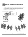
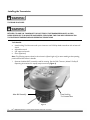
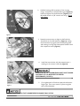
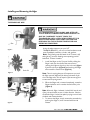
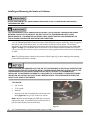
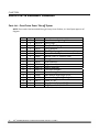
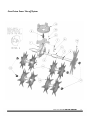
DR® TRIMMER/MOWERTM
SAFETY & OPERATING INSTRUCTIONS
GEAR-DRIVEN POWER TAKE-OFF SYSTEM™
1.
READ AND UNDERSTAND THIS MANUAL AND ALL
INSTRUCTIONS BEFORE OPERATING THE DR TRIMMER/MOWER
WITH GEAR-DRIVEN POWER TAKE-OFF SYSTEM™
And congratulations on your purchase of a new add-on accessory for your DR
TRIMMER/MOWER!
We have done our utmost to ensure that your DR and all Country Home Products, Inc.
accessories will be one of the most trouble-free and satisfying pieces of equipment you
have ever owned. Please let us know of any questions you may have. We want to
answer them as quickly as possible. When you do call, please have your order number
handy. For technical assistance, please call Toll-Free 1-800-DR-OWNER(376-9637) and
one of our Technical Support Representatives will be happy to help you. We also hope
to hear from you on how much you like your new helper.
And, please tell your friends about your new DR TRIMMER/MOWER Gear-Driven
Power Take-Off System! Having DR Owners spread the word about our products and
our way of doing business is the best advertising we can have, and the best way to help
us provide even better service in the years to come.
Thanks once again!
for all of us at
Country Home Products, Inc.
SALES MANAGER
COPYRIGHT
©2006 Country Home Products, Inc. All rights reserved.
Country Home Products, Inc.
Meigs Road
P.O. Box 25
Vergennes, VT 05491
Toll-free phone: 1-800-DR-OWNER (376-9637)
Fax: 1-802-877-1213
Web site: www.dr-owner.com
E-mail: [email protected]
II
DR® TRIMMER/MOWER™ GEAR-DRIVEN POWER TAKE-OFF SYSTEM™
Table of Contents
CHAPTER 1 .............................................................................................................................1
INTRODUCING THE DR GEAR-DRIVEN POWER TAKE-OFF SYSTEM........................1
Conventions used in this manual....................................................................................1
CHAPTER 2 .............................................................................................................................2
SAFETY CONSIDERATIONS ...........................................................................................2
Preparing to Use the DR Gear-Driven Power Take-Off System......................................2
Safety Information Labels ................................................................................................2
Protecting Yourself...........................................................................................................2
Operating the Machine Safely .........................................................................................3
Additional Information and Potential Changes ..............................................................4
CHAPTER 3 .............................................................................................................................5
INSTALLING YOUR DR GEAR-DRIVEN POWER TAKE-OFF SYSTEM..........................5
DR Gear-Driven Power Take-Off System.........................................................................5
Installing the Transmission .............................................................................................6
Before Installing the Accessories.....................................................................................8
Installing and Removing the Edger .................................................................................9
Installing and Removing the Aerator or Cultivator .......................................................10
CHAPTER 4 ...........................................................................................................................12
USING YOUR DR GEAR-DRIVEN POWER TAKE-OFF SYSTEM AND ACCESSORIES12
Edger Use .......................................................................................................................13
Cultivator Use.................................................................................................................13
Aerator Use.....................................................................................................................14
CHAPTER 5 ...........................................................................................................................15
TROUBLESHOOTING AND WARRANTY.....................................................................15
Troubleshooting Table ...................................................................................................15
CHAPTER 6 ...........................................................................................................................16
PARTS LIST & ASSEMBLY DIAGRAM...........................................................................16
Parts List – Gear-Driven Power Take-off System ..........................................................16
Gear-Driven Power Take-off System ..............................................................................17
Daily Checklist for the DR Gear-Driven Power Take-Off System..................................18
CALL TOLL FREE 1-800-DR-OWNER
III
IV
DR® TRIMMER/MOWER™ GEAR-DRIVEN POWER TAKE-OFF SYSTEM™
CHAPTER 1
INTRODUCING THE DR GEAR-DRIVEN POWER TAKE-OFF
SYSTEM
This manual will help you set up and safely operate your new DR Gear-Driven Power Take-Off System.
Careful adherence to the safety and operating instructions in this manual will ensure many years of
productive use.
Please let us know of any questions you may have. We want to answer them as quickly as possible.
When you do call, please have your order number handy. For technical assistance, please call Toll-Free
1-800-DR-OWNER(376-9637) and one of our Technical Support Representatives will be happy to help
you.
Conventions used in this manual
THE EXCLAMATION POINT WITHIN A TRIANGLE ALERTS YOU TO ESSENTIAL OPERATING, SAFETY,
AND MAINTENANCE (SERVICING) INSTRUCTIONS.
THIS INDICATES A HAZARDOUS SITUATION, WHICH, IF NOT AVOIDED, COULD RESULT IN MINOR
OR MODERATE INJURY.
THIS INFORMATION IS IMPORTANT IN THE PROPER USE OF YOUR MACHINE. FAILURE TO FOLLOW
THIS INSTRUCTION COULD RESULT IN DAMAGE TO YOUR MACHINE OR PROPERTY.
Tip: This is a helpful hint to guide you in getting the most out of your DR Gear-Driven Power Take-Off
System.
Tools Needed: This indicates you will need a special tool to perform a maintenance function on your
machine.
Note: This information may be helpful to you.
If you are ever unsure about an action you are about to take, don’t do it. Contact Country Home
Products’ toll-free support at 1-800-DR-OWNER (376-9637) for help or information.
CALL TOLL FREE 1-800-DR-OWNER
1
CHAPTER 2
SAFETY CONSIDERATIONS
Taking the time to read and observe all safety instructions will ensure many years of productive use from
your DR Gear-Driven Power Take-Off System and help you avoid injury. Please take a few moments to
read the following guidelines for safely operating your new machine.
Preparing to Use the DR Gear-Driven Power Take-Off System
•
Read these Safety & Operating Instructions before you use the DR Gear-Driven Power Take-Off
System. Become familiar with the operation and service recommendations to ensure the best
performance from your new accessory.
Safety Information Labels
Consult the Safety Considerations chapter in your DR TRIMMER/MOWER Safety & Operating
Instructions manual for more information about using and ordering safety information labels. Replace
damaged or missing safety labels immediately.
Protecting Yourself
2
•
Always wear protective goggles while using the DR Gear-Driven Power Take-Off System to protect
your eyes from possible thrown objects. Goggles are provided with your DR TRIMMER/MOWER.
•
Do not, under any conditions, remove, bend, cut, fit, weld, or otherwise alter standard parts on the
DR Gear-Driven Power Take-Off System. Modifications to your accessory could cause personal
injuries and will void your warranty.
•
Wear shoes with non-slip treads when using your DR TRIMMER/MOWER and DR Gear-Driven
Power Take-Off System. Do not use the machine while barefoot or wearing open sandals.
•
Wear long pants while using your DR TRIMMER/MOWER and DR Gear-Driven Power Take-Off
System.
•
Avoid wearing loose clothing or jewelry, which might be caught on the mower’s moving parts.
•
Use earmuffs or earplugs to protect your hearing.
•
Always keep safety guards in place and in working order.
•
Always check the alignment of moving parts and for damaged or worn parts
DR® TRIMMER/MOWER™ GEAR-DRIVEN POWER TAKE-OFF SYSTEM™
Operating the Machine Safely
THE ITEMS LISTED IN THIS SECTION WILL HELP YOU KEEP YOUR DR GEAR-DRIVEN POWER TAKEOFF SYSTEM OPERATING SMOOTHLY AND, MOST IMPORTANTLY, PREVENT INJURY TO YOURSELF
OR OTHERS. PLEASE REVIEW THEM CAREFULLY BEFORE STARTING YOUR MACHINE.
•
To be safe, do not operate the machine near children or pets, and never allow children to operate
the machine. Keep at least 50 feet clear of bystanders and always turn the machine off when
someone approaches.
•
Never allow people who are unfamiliar with these instructions to use the machine.
•
The DR Gear-Driven Power Take-Off System uses rotating blades, which could cause serious injury
if handled while the machine is running. Keep your hands and feet clear of the blade area and do not
attempt to adjust blades while the machine is running.
•
ALWAYS shut off the engine and remove the spark plug wire before adjusting the machine. If you
have to stop to remove grass or debris from the underside of the frame, always disconnect the spark
plug wire first.
•
The exhaust area on the engine becomes very hot with use. Allow the engine to cool before doing
maintenance or making adjustments.
•
The DR Gear-Driven Power Take-Off System heats up during operation. Touching it could cause
serious burns. Typical surface temperatures can range between 110 and 180 degrees Fahrenheit.
Wait until the trimmer and the DR Gear-Driven Power Take-Off System are cool before performing
any maintenance procedures. Typically, this can take 15–30 minutes depending on the outdoor
temperature and conditions of use.
•
When operating over uneven terrain and slopes, use EXTREME CAUTION to ensure solid and firm
footing.
•
Use extra caution when using the DR Gear-Driven Power Take-Off System in wet or slippery
conditions.
•
Check the area you will be working in for sticks, stones, gravel, roots, and bits of debris. Remove any
obstructions before starting to operate equipment. Failure to do this could cause personal injury or
property damage from thrown objects.
•
Turn off the engine whenever you are not operating the machine. Never leave the engine running
when refueling, changing attachments, checking, cleaning or working on the machine.
•
Use the machine only in daylight or good artificial light.
•
Don't hurry or take things for granted while using the DR Gear-Driven Power Take-Off System.
•
Do not operate the machine when under the influence of alcohol or medication.
•
Watch for traffic when using the DR Gear-Driven Power Take-Off System near roadways.
CALL TOLL FREE 1-800-DR-OWNER
3
•
Always make certain nuts and bolts are tight to assure a safe working condition.
•
Use only manufacturer-recommended replacement parts and accessories.
Note: No list of warnings and cautions can be all-inclusive. The operator must apply common sense and
operate the DR Gear-Driven Power Take-Off System in a safe manner.
Additional Information and Potential Changes
Country Home Products, Inc. reserves the right to discontinue, change, and improve its products at any
time without notice or obligation to the purchaser. The descriptions and specifications contained in this
manual were in effect at printing. Equipment described within this manual may be optional. Some
illustrations may not be applicable to your machine.
4
DR® TRIMMER/MOWER™ GEAR-DRIVEN POWER TAKE-OFF SYSTEM™
CHAPTER 3
INSTALLING YOUR DR GEAR-DRIVEN POWER TAKE-OFF
SYSTEM
This chapter outlines a few simple steps you will need to follow to install your new DR GearDriven Power Take-Off System. Once you have completed this installation, you can attach and
use your new accessories in minutes. It may be helpful to familiarize yourself with the
components of the DR Gear-Driven Power Take-Off System by reviewing the pictures below
before beginning the steps outlined in this chapter.
DR Gear-Driven Power Take-Off System
Shaft Extension –
included but not
attached.
Edger
Gear-Driven PTO Unit
Cultivator
Aerator
Figure 1
CALL TOLL FREE 1-800-DR-OWNER
5
Installing the Transmission
BEFORE PERFORMING ANY MAINTENANCE PROCEDURE, STOP THE ENGINE AND DISCONNECT
THE SPARK PLUG WIRE.
THE TRANSMISSION IS HOT DURING AND AFTER USE. TYPICAL SURFACE TEMPERATURES RANGE
BETWEEN 110 AND 180° FAHRENHEIT. DO NOT TOUCH THE TRANSMISSION UNTIL A COOL
DOWN PERIOD OF 15-30 MINUTES HAS PASSED. COOL DOWN TIME CAN VARY DEPENDING ON
THE OUTDOOR TEMPERATURE AND OPERATING CONDITIONS.
Tools Needed:
•
Head-Locking Tool that came with your trimmer or a #3 Phillips head screwdriver with at least a 6"
shank.
Adjustable wrench
5/8" open-end wrench
Pliers (Optional)
•
•
•
Note: The following steps are based on the trimmer’s left and right as if you were standing at the operating
position behind the trimmer’s handles.
1.
Remove the Mow-Ball™ assembly used for mowing. See the DR® Trimmer/ Mower™ Safety &
Operating Instructions for step-by-step instructions (Figure 2)
Mow-Ball Assembly
Head Locking
Tool inserted here
Figure 2
6
DR® TRIMMER/MOWER™ GEAR-DRIVEN POWER TAKE-OFF SYSTEM™
2.
Hold the bearing shaft to prevent it from turning
using a screwdriver or the head-locking tool (Figure 2).
Install and tighten the shaft extension (Figure 3) with
adjustable wrench or 5/8" wrench until snug. Do not
over tighten.
3.
Rotate the transmission to align its shaft with the
slotted hole in the shaft extension (Figure 4), sliding
the transmission up against the lower bearing plate
and rotating it to align the three captive fasteners with
their respective inserts (Figure 4).
Inserts
Shaft Extension
Figure 3
Insert
Front of
machine
Captive Screws
Figure 4
4.
Bulge
L marking
Front of
machine
Figure 5
Install the transmission with the transmission’s L
marking on the trimmer’s left side (Figure 5).
THE BULGE ON THE TRANSMISSION MUST FACE TOWARD
THE FRONT OF THE MACHINE FOR PROPER
PERFORMANCE (FIGURE 5).
Captive
Screw
5.
First, tighten each of the three captive thumbscrews
finger tight. Then use a wrench or pliers to tighten
each screw alternately.
DO NOT OVER TIGHTEN THE THUMBSCREWS OR DAMAGE MAY OCCUR.
CALL TOLL FREE 1-800-DR-OWNER
7
Before Installing the Accessories
Each attachment has two slots in the axle that ends in a J feature. The shafts that install on the side of
the transmission marked with an R have a semi-circular notch in the end of the shaft by the slot. The
shafts that install on the side of the transmission marked with an L do not have this notch (Figure 6).
J-Shaped Slot
J-Shaped Slot
Notch
(4 places)
No notches
Left side attachment
Right side attachment
Figure 6
THE ACCESSORIES HAVE CAPS ON THE OUTSIDE ENDS: A RED CAP ON THE RIGHT AND A BLACK CAP
ON THE LEFT. BE SURE TO INSTALL THE RED-CAPPED END ON THE RIGHT SIDE OF THE
TRANSMISSION AND THE BLACK-CAPPED END ON THE LEFT SIDE OF THE TRANSMISSION.
INSTALLING THE ACCESSORY INCORRECTLY CAN CAUSE THE ATTACHMENT TO COME OFF DURING
OPERATION.
8
DR® TRIMMER/MOWER™ GEAR-DRIVEN POWER TAKE-OFF SYSTEM™
Installing and Removing the Edger
BEFORE PERFORMING ANY MAINTENANCE PROCEDURE, STOP THE ENGINE AND DISCONNECT
THE SPARK PLUG WIRE.
THE TRANSMISSION IS HOT DURING AND AFTER USE.
TYPICAL SURFACE TEMPERATURES RANGE BETWEEN 110
AND 180° FAHRENHEIT. DO NOT TOUCH THE
TRANSMISSION UNTIL A COOL DOWN PERIOD OF 15-30
MINUTES HAS PASSED. COOL DOWN TIME CAN VARY
DEPENDING ON THE OUTDOOR TEMPERATURE AND
OPERATING CONDITIONS.
J Slot
Using the edger accessory on your DR®
TRIMMER/MOWER™, you can cut clean borders around
trees, flowerbeds, walkways, shrubs, and gardens.
Figure 7
Note: The following steps are based on the Trimmer’s left
and right as if you were standing at an operating position
behind the Trimmer’s handles.
1.
Drive Pin
Figure 8
Install the Edger on the Trimmer’s left by sliding the
Edger’s axle over the shaft of the transmission,
rotating the Edger to align the J-slot in the axle (Figure
7) with the drive pin (Figure 8) and pushing the Edger
axle toward the transmission (Figure 9).
Note: There is a spring that you will compress as you push
the Edger onto the shaft until the drive pins bottom on the
slot in the Edger axle. This will require a fair amount of force
to overcome the spring tension.
2.
When the Edger axle is inserted completely, rotate the
Edger clockwise until it reaches the end of the J-slot
(Figure 9).
Note: When the Edger is released, it should lock into the end
of the J-slot and should not turn in either direction. Check to
see that the Edger is locked into place by trying to turn it both
clockwise and counterclockwise.
3.
Figure 9
To remove the Edger, simply reverse the procedure by
pushing the Edger in, twist counterclockwise and
release.
CALL TOLL FREE 1-800-DR-OWNER
9
Installing and Removing the Aerator or Cultivator
BEFORE PERFORMING ANY MAINTENANCE PROCEDURE, STOP THE ENGINE AND DISCONNECT
THE SPARK PLUG WIRE.
THE TRANSMISSION IS HOT DURING AND AFTER USE. TYPICAL SURFACE TEMPERATURES RANGE
BETWEEN 110 AND 180° FAHRENHEIT. DO NOT TOUCH THE TRANSMISSION UNTIL A COOL
DOWN PERIOD OF 15-30 MINUTES HAS PASSED. COOL DOWN TIME CAN VARY DEPENDING ON
THE OUTDOOR TEMPERATURE AND OPERATING CONDITIONS.
Your DR TRIMMER/MOWER Gear-Driven Power Take-Off System aerator attachment slices through the
top layer of sod to help deliver water, air, and nutrients to the roots of your plants. The cultivator
attachment is similar in appearance to the aerator with the exception of its alternating bent blades (see
Figure 1 on Page 7). These blades allow the cultivator to churn weeds and dead material over into the
soil as you move your machine. Use the cultivator to maintain garden beds you have previously prepared
or tilled.
Note: The following steps are based on the trimmer’s left and right as if you were standing at the operating
position behind the trimmer’s handles.
THE CULTIVATOR AND AERATOR HAVE CAPS ON THE OUTSIDE ENDS: A RED CAP ON THE RIGHT AND
A BLACK CAP ON THE LEFT. BE SURE TO INSTALL THE RED-CAPPED END ON THE RIGHT SIDE OF THE
TRANSMISSION AND THE BLACK-CAPPED END ON THE LEFT SIDE OF THE TRANSMISSION.
INSTALLING THE ACCESSORY INCORRECTLY CAN CAUSE THE ATTACHMENT TO COME OFF DURING
OPERATION. SEE FIGURE 6 ON PAGE 10 FOR A DESCRIPTION OF THE DIFFERENCES BETWEEN THE
RIGHT & LEFT HAND ATTACHMENTS.
Tools Needed:
•
3/8" wrench
•
7/16" wrench
•
Hammer
1.
Remove a bolt and nut holding the main frame to the
deck (Figure 10) using a 7/16" and a 3/8" wrench.
Remove this bolt
Note: Machines purchased after July 2002 may not need to
perform these steps. Your machine may not have this bolt; if
you don’t have the bolt, continue with step 3.
Figure 10
10
®
DR TRIMMER/MOWER™ GEAR-DRIVEN POWER TAKE-OFF SYSTEM™
2.
Replace the removed bolt with the supplied black
plastic button (Figure 11). Simply push the button
into the hole or gently tap in place with a hammer.
3.
Install the aerator or cultivator on the trimmer’s
right by sliding the attachment’s axle over the shaft
of the transmission, rotating the attachment to
align the slot in the axle with the drive pin and
pushing the attachment axle toward the
transmission (Figure 12).
Insert plastic button
Note: The right side attachments have a red cap and 2
semi-circular notches in the axle (see Figure 6 on page 10).
There is a spring that you will compress as you push the
attachment onto the shaft until the drive pins bottom on
the slot in the attachment’s axle. This will require a fair
amount of force to overcome the spring tension.
Figure 11
Push in
J-Slot
Drive Pin
4.
Note: When the attachment is released, it should lock into
the end of the J-slot and should not turn in either direction.
Check to see that the attachment is locked into place by
trying to turn it both clockwise and counterclockwise.
5.
Figure 12
Compress
Spring
When the attachment axle is inserted completely,
rotate the attachment clockwise until it reaches the
end of the J-slot (Figure 13).
To install the aerator or cultivator left axle, repeat
the instructions above.
Note: The attachment’s left axle has a black cap and does
not have a semi-circular notch at the end of the axle near the
J-slot (see Figure 6 on page 10).
Turn and release
to lock in J-Slot
Figure 13
CALL TOLL FREE 1-800-DR-OWNER
11
CHAPTER 4
USING YOUR DR GEAR-DRIVEN POWER TAKE-OFF SYSTEM
AND ACCESSORIES
This chapter covers the procedures for operating your new DR TRIMMER/MOWER Gear-Driven Power
Take-Off System and also discusses basic operation features.
THE TRANSMISSION IS HOT DURING AND AFTER USE. TYPICAL SURFACE TEMPERATURES RANGE
BETWEEN 110 AND 180° FAHRENHEIT. DO NOT TOUCH THE TRANSMISSION UNTIL A COOL
DOWN PERIOD OF 15-30 MINUTES HAS PASSED. COOL DOWN TIME CAN VARY DEPENDING ON
THE OUTDOOR TEMPERATURE AND OPERATING CONDITIONS.
Before using your trimmer’s accessories, be prepared to resist the force the accessories create.
THE EDGER, AERATOR, AND CULTIVATOR PULL THE TRIMMER FORWARD, AWAY FROM YOU. THE
FORCE YOU EXPERIENCE VARIES DEPENDING ON THE HARDNESS OF THE SOIL AND THE NUMBER
OF ROCKS YOU ENCOUNTER. TYPICALLY, YOU WILL NEED TO PULL BACKWARD AS THE MACHINE
PULLS FORWARD. IF YOU RESIST THE PULL OF THE MACHINE, THE ATTACHMENTS OPERATE MORE
EFFECTIVELY. IF YOU PROVIDE LITTLE RESISTANCE, THE ATTACHMENTS WILL OPERATE LESS
EFFECTIVELY. YOU MAY WANT TO PULL THE MACHINE BACKWARD FOR OPTIMUM PERFORMANCE.
WHEN USING THE DR TRIMMER/MOWER SELF-PROPELLED MODEL, DO NOT ENGAGE THE WHEEL
DRIVE WHEN USING THE ATTACHMENT ACCESSORIES. YOU WILL NEED TO RESIST THE PULLING
FORWARD ACTION OF THE ATTACHMENTS AS MENTIONED ABOVE, WHICH MAY RESULT IN DAMAGE
TO THE SELF-PROPELLED DRIVE SYSTEM IF IT IS ENGAGED. THE PTO ATTACHMENTS WILL PULL THE
MACHINE FORWARD WITHOUT ENGAGING THE DRIVE SYSTEM.
To operate the DR TRIMMER/MOWER with accessories attached:
12
1.
Engage the Gear-Driven Power Take-Off System by pulling the bail bar of the machine back against
the handle.
2.
Disengage the Gear-Driven Power Take-Off System by releasing the bail bar.
DR® TRIMMER/MOWER™ GEAR-DRIVEN POWER TAKE-OFF SYSTEM™
Edger Use
The Edger is designed to cut a clean straight edge in sod and grass along sidewalks and driveways.
1.
When transporting the DR TRIMMER/MOWER with the Edger attachment (see Figure 1) to the site
where you wish to use it, be sure to push down on the handlebars to raise the Edger so that it does
not scrape along the ground. If the Edger scrapes along the ground or is bumped, it may unlock
from the PTO and rotate backwards. This may cause the Edger to fall off of the PTO. If the Edger is
installed on the operator’s right side, it may also unlock and loosen during use. The Edger must be
installed on the operator’s left side for proper functioning of the Edger (see Figure 8).
2.
Align the Edger with the line of cut that you wish to make. If you are cutting beside a sidewalk, it is
best to have most of the machine on the sidewalk and one tire on the grass.
3.
When you are at the site where you wish to edge, start the DR TRIMMER/MOWER engine; then
push down on the handlebars to lift the Edger off of the ground. Pull the bail bar back to engage the
PTO and start the Edger rotating.
4.
Hold back on the handlebars and slowly lower the Edger into the ground. The weight of the DR
TRIMMER/MOWER will cause the Edger to cut into the sod and try to pull the machine forward as it
cuts. Hold the DR TRIMMER/MOWER back so that the Edger cuts completely down into the sod
and the hub of the Edger is on top of the ground.
5.
Continue to hold back on the handlebars and slowly allow the Edger to work forward to cut new sod
and grass. A back and forth motion, by letting the machine move slowly forward and then pulling it
slowly back towards you, is sometimes more effective than trying to move steadily forward.
6.
After you have completed your cut, you will need to pick up any sod that is cut off that you wish to
discard or compost. It is best to pick up this sod right away so that it doesn’t get packed back down
into the cut you just made. A straight edged shovel or hoe is best for picking up the loose sod.
Cultivator Use
The cultivator is designed to fluff up soil that has previously been tilled, such as a flower or vegetable
garden, to churn in fertilizer, prepare the soil for planting, or remove weeds.
1.
When transporting the DR TRIMMER/MOWER with the Cultivator attachment (see Figure 1) to the
site where you wish to cultivate, be sure to push down on the handlebars to raise the Cultivator
blades so that they do not scrape along the ground. If the blades bump or scrape along the ground,
they can become unlocked and rotate off of the PTO.
2.
When you are at the site you wish to cultivate, start the DR TRIMMER/MOWER engine. Hold back
on the machine as you pull back on the bail bar to engage the PTO. As the Cultivator blades start to
churn into the soil, they will try to pull the machine forward.
3.
Continue to hold back on the handlebars and slowly allow the Cultivator to pull the machine forward
to cultivate new soil. A back and forth motion, by letting the machine move slowly forward and then
pulling it slowly back towards you, is sometimes more effective than trying to move steadily forward.
4.
Some users prefer to continually pull the cultivator backward to maximize the work being done to
churn the soil. We recommend trying both approaches and selecting the approach that works best
for you.
CALL TOLL FREE 1-800-DR-OWNER
13
Aerator Use
The Aerator is designed to cut grooves into the sod so that water and nutrients can penetrate the sod
and get directly to the root system.
14
1.
When transporting the DR TRIMMER/MOWER with the Aerator attachment (see Figure 1) to the site
where you wish to aerate, be sure to push down on the handlebars to raise the Aerator blades so
that they do not scrape along the ground. If the blades bump or scrape along the ground, they can
become unlocked and rotate off of the PTO.
2.
When you are at the site you wish to aerate, start the DR TRIMMER/MOWER engine. Hold back on
the machine as you pull back on the bail bar to engage the PTO. As the Aerator blades start to
churn into the soil, they will try to pull the machine forward.
3.
Continue to hold back on the handlebars and slowly allow the Aerator to pull the machine forward to
cut into new soil.
4.
Continue to let the Aerator work around the yard, spacing your passes so that the Aerator grooves
are approximately evenly spaced. Dividing your lawn into smaller sections and then working around
each section until it is aerated is an effective way to make steady progress. Each area that is
completed is then ready for application of fertilizer and water.
DR® TRIMMER/MOWER™ GEAR-DRIVEN POWER TAKE-OFF SYSTEM™
CHAPTER 5
TROUBLESHOOTING AND WARRANTY
Most problems are easy to fix. Consult the Troubleshooting Table below for common problems
and their solutions. If you continue to experience problems, call Country Home Products, Inc.
for support.
Troubleshooting Table
BEFORE PERFORMING ANY MAINTENANCE PROCEDURE, STOP THE ENGINE AND DISCONNECT THE
SPARK PLUG WIRE.
THE TRANSMISSION IS HOT DURING AND AFTER USE. TYPICAL SURFACE TEMPERATURES RANGE
BETWEEN 110 AND 180° FAHRENHEIT. DO NOT TOUCH THE TRANSMISSION UNTIL A COOL DOWN
PERIOD OF 15-30 MINUTES HAS PASSED. COOL DOWN TIME CAN VARY DEPENDING ON THE
OUTDOOR TEMPERATURE AND OPERATING CONDITIONS.
SYMPTOM
TINES WILL NOT
TURN.
POSSIBLE CAUSE
Ö THE SHAFT EXTENSION IS MISSING. SEE PAGE 9,
FIGURE 3.
Ö THE TINES ARE IN BACKWARDS. SEE PAGE 10, FIGURE 6.
Ö THE TRIMMER BELT MAY NEED TO BE REPLACED. SEE
THE DR TRIMMER/MOWER SAFETY & OPERATING
INSTRUCTIONS MANUAL FOR MORE INFORMATION.
Ö IF THE PROBLEM PERSISTS, CALL 1(800) DROWNER (376-9637) FOR ASSISTANCE.
Ö
TINES FALL OFF.
Ö THE PTO IS INSTALLED BACKWARDS. SEE PAGE 9.
Ö THE TINES ARE REVERSED. SEE PAGE 10, FIGURE 6.
Ö THE TINES ARE NOT LOCKED IN PLACE. SEE FIGURE 8
OR 13.
Ö THE TINES ARE ROLLED ACROSS THE GROUND
SURFACE WHILE NOT BEING DRIVEN.
Ö IF THE PROBLEM PERSISTS, CALL 1(800) DROWNER (376-9637) FOR ASSISTANCE.
CALL TOLL FREE 1-800-DR-OWNER
15
CHAPTER 6
PARTS LIST & ASSEMBLY DIAGRAM
Parts List – Gear-Driven Power Take-off System
NOTE: Part numbers listed are available through Country Home Products, Inc. Not all parts appear on all
diagrams.
16
Ref #
Qty
1
2
3
4
5
6
7
8
9
10
11
12
13
14
15
16
17
18
1
2
2
2
2
3
3
3
1
1
1
1
1
1
1
4
1
1
Part #
Description
160771 C
160761 A
160751
160741
160781
160721
160901
164721
160791
188661
160931 A
160951 A
164201
164001
164101
164111
164161
164151
Transmission, Right Angle Drive
Spring Cage
Compression Spring
Spring Retainer
Pin, Coiled Spring, ¼" x 1½", Heavy Duty
Screw, Thumb, Captive
Washer, Lock, ¼" Internal Tooth
O-ring
Shaft Extension
Edger Assembly
Aerator Assembly
Cultivator Assembly
Lower Bearing Plate with Inserts
A&O Manual Right Angle Drive
Parts List Diagram, Right Angle Drive
Insert, ¼"–20
Plug, Round, Black, 1.00" OD
Plug, Tapered, Red, 0.94" OD
DR® TRIMMER/MOWER™ GEAR-DRIVEN POWER TAKE-OFF SYSTEM™
Gear-Driven Power Take-off System
CALL TOLL FREE 1-800-DR-OWNER
17
Daily Checklist for the DR Gear-Driven Power Take-Off System
To help maintain your DR Gear-Driven Power Take-Off System for optimum performance, we
recommend you follow this checklist each time you use your machine.
[ ] HARDWARE: Check all nuts and bolts to be sure that the components are secure.
[ ] Follow the daily checklist as outlined in your DR TRIMMER/MOWER Safety & Operating
Instructions manual.
COUNTRY HOME PRODUCTS, Inc.
MEIGS ROAD, P.O. BOX 25, VERGENNES, VERMONT 05491
1-800-DR-OWNER (376-9637) • www.dr-owner.com
©2006 CHP, Inc. 164001A