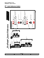
1
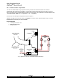
FireFinderTM
AS1603.4
OPERATORS MANUAL
Document No
G0109WO1
Model No
G0109
Serial No
………………………………………
Date of Manufacture
………………………………………
Revision
3
AMPAC TECHNOLOGIES PTY LTD
HEAD OFFICE
PERTH:
97 WALTERS DRIVE
OSBORNE PARK 6017
WESTERN AUSTRALIA
PH:
FAX:
E-MAIL:
Website:
61-8-9242 3333
61-8-9242 3334
[email protected]
www.ampac.net
NOTE: DUE TO AMPAC’s COMMITMENT TO CONTINUOUS IMPROVEMENT
SPECIFICATIONS MAY CHANGE WITHOUT NOTICE.
UNCONTROLLED DOCUMENT
Ampac Technologies Pty Ltd
FireFinderTM Operators Manual
1 Fire Brigade Responding To Alarm
1. Indicators
2. Isolate
-Alarm Indicator Flashing.
-Location of Alarm on LCD Display.
-First Alarm Displayed.
External Bell Isolate Warning System
Press
Press
EXTERNAL BELL
ISOLATE
3. Acknowledge
WARNING SYS
ISOLATE
Alarm
Press
ACKNOWLEDGE
4. Isolate
Alarm
Press
I S O L AT E
5. If
multiple alarms exist repeat 3 and 4 for second alarm and so on.
6. To
Reset Panel
Press
RESET
PAGE 1
DOC No:G0109WO1.doc
DIR: L:\MANUALS
DATE: 30/11/00
REVISION: 3
Ampac Technologies Pty Ltd
FireFinderTM Operators Manual
2 Table Of Contents
1
Fire Brigade Responding To Alarm ...................................................................... 1
2
Table Of Contents .................................................................................................. 2
3
About This Manual ................................................................................................. 4
3.1
Purpose ........................................................................................................................................ 4
3.2
Scope............................................................................................................................................ 4
3.3
References ................................................................................................................................... 4
4
Non Disclosure Agreement ................................................................................... 5
5
System Overview.................................................................................................... 6
6
Placing The System Into Operation ...................................................................... 7
6.1
Unpacking .................................................................................................................................... 7
6.2
Anti-Static Precautions............................................................................................................... 7
6.3
Working On The System............................................................................................................. 7
6.4
The Cabinet.................................................................................................................................. 7
6.5
Mounting The Cabinet ................................................................................................................ 8
6.5.1
6.6
Connecting the Mains............................................................................................................... 10
6.7
FireFinderTM Description ............................................................................................................ 11
6.8
List of Compatible FireFinderTM Modules ................................................................................ 13
6.8.1
Brigade / PSU Monitor Board ........................................................................................... 14
6.8.2
Conventional Zone Board ................................................................................................. 16
6.8.3
Addressable Loop Board .................................................................................................. 17
6.8.4
16/16 Input / Output Board ................................................................................................ 18
6.8.5
8 Way Relay Board............................................................................................................. 18
6.8.6
16 Way Input Board ........................................................................................................... 19
6.8.7
AS1668 Control Module .................................................................................................... 19
6.8.8
Serial Relay Board ............................................................................................................. 20
6.8.9
32 Zone LED Mimic Board................................................................................................. 20
6.8.10
Valve Display Module ........................................................................................................ 21
6.8.11
Pump Display Module........................................................................................................ 21
6.9
7
Mounting The Cabinet cont (SP8) ...................................................................................... 9
Network Compatible Modules.................................................................................................. 22
6.9.1
Controller Interface Card................................................................................................... 22
6.9.2
Network Interface Card...................................................................................................... 22
6.9.3
Liquid Crystal Display Repeater Panel ............................................................................ 23
6.9.4
LED Repeater Board .......................................................................................................... 24
FireFinderTM Operation .......................................................................................... 25
7.1
The Control Panel ..................................................................................................................... 25
7.2
The Default LCD Display .......................................................................................................... 27
7.3
Incoming Alarm Signal ............................................................................................................. 28
7.4
Accessing a Loop, Sensor or Zone......................................................................................... 28
7.5
Accessing Functions and Menus ............................................................................................ 28
PAGE 2
DOC No:G0109WO1.doc
DIR: L:\MANUALS
DATE: 30/11/00
REVISION: 3
Ampac Technologies Pty Ltd
FireFinderTM Operators Manual
7.6
The Main Menu .......................................................................................................................... 29
7.6.1
Status Menu........................................................................................................................ 29
7.6.2
Testing Menu...................................................................................................................... 30
7.7
Function Menu........................................................................................................................... 30
7.7.1
Forgotten Passwords ........................................................................................................ 31
7.8
Manual I/O Control .................................................................................................................... 31
7.9
Programming ............................................................................................................................. 32
7.10
Passwords ................................................................................................................................. 33
8
List of Compatible Devices ................................................................................. 34
9
Certification Information...................................................................................... 36
10 Operational Parameters....................................................................................... 37
11 Troubleshooting Chart......................................................................................... 38
12 Appendix ............................................................................................................... 39
13 Glossary Of Terms ............................................................................................... 40
14 Definitions............................................................................................................. 41
Quick Reference Guides............................................................................................ 43
PAGE 3
DOC No:G0109WO1.doc
DIR: L:\MANUALS
DATE: 30/11/00
REVISION: 3
Ampac Technologies Pty Ltd
FireFinderTM Operators Manual
3 About This Manual
3.1 Purpose
The purpose of this manual is to assist you in the installation and operation of the FireFinderTM Fire
Detection System.
3.2 Scope
The information within this manual is only available to and for the use of personnel engaged in the
installation and operation of the FireFinderTM Fire Detection System.
3.3 References
FireFinderTM Technical Manual
FireFinderTM Detector manual
AMPAC Product Data Sheets
Australian Standards:
AS1603.4 - 1987 Automatic Fire Detection and Alarm Systems part 4 - Control and Indicating Equipment.
AS1670 - 1995 Automatic Fire Detection and Alarm Systems - system design, installation, and
commissioning.
AS1851.8 - 1987 Maintenance of Fire Protection equipment part 8 - Automatic Fire detection and Alarm
Systems.
AS1851.8-Supp 1-1990 System certificate and maintenance records.
PAGE 4
DOC No:G0109WO1.doc
DIR: L:\MANUALS
DATE: 30/11/00
REVISION: 3
Ampac Technologies Pty Ltd
FireFinderTM Operators Manual
4 Non Disclosure Agreement
This contract has been entered into by the person or company user of this document (hereafter called
the Trader) and AMPAC Technologies (hereafter called AMPAC) of 97 Walters Drive, Osborne Park
Western Australia 6017. Under terms and conditions as specified hereunder.
Whereas AMPAC and the Trader for their mutual benefit and pursuant to a working relationship which
may be established, anticipate that AMPAC will disclose in the form of this document, information of a
secret, or confidential or proprietary nature (hereinafter collectively referred to as Proprietary
Information).
Whereas AMPAC desires to ensure that the confidentiality of any Proprietary Information is maintained in
accordance with the terms of this Agreement;
NOW, THEREFORE, in consideration of the foregoing premises, and the mutual covenants contained
herein, the Trader hereby agrees as follows:
1. The Trader shall hold in trust and confidence, and not disclose to any person outside its
organisation, any Proprietary information which is disclosed to the Trader by AMPAC under this
Agreement. Proprietary Information disclosed under this Agreement may be used by the Trader only
for the purpose of carrying out work on or with AMPAC supplied equipment and may not be used for
any other purpose whatsoever.
2. The Trader shall disclose Proprietary Information received by AMPAC under this Agreement to
persons within its organisation only if such persons are legally bound in writing to protect the
confidentiality of such Proprietary Information.
3. The undertakings and obligations of the Trader under this Agreement shall not apply to any
Proprietary Information which :
1. is disclosed in a printed publication available to the public, is described in patent anywhere in the
world, or is otherwise in the public domain at the time of disclosure;
2. is generally disclosed to third parties by AMPAC without restriction on such third parties;
3. is shown by the Trader to have been in its possession prior to the receipt thereof from AMPAC;
4. is approved for release by written authorisation of AMPAC; or
5. is not designated by AMPAC in writing or by appropriate stamp or legend to be of a secret,
confidential or proprietary nature.
4. This Agreement will be binding upon and inure to the benefit of the parties hereto, and their
respective successors and assigns.
5. This Agreement, and all rights and obligations hereunder, shall expire on the 10th anniversary of the
date of issue of this document.
These terms are accepted by the Trader on receipt and retention of this document.
PAGE 5
DOC No:G0109WO1.doc
DIR: L:\MANUALS
DATE: 30/11/00
REVISION: 3
Ampac Technologies Pty Ltd
FireFinderTM Operators Manual
5 System Overview
The FireFinderTM is an Intelligent Analogue, Addressable and Conventional Fire Alarm Control Panel
capable of supporting:
•
•
•
•
•
•
•
•
•
•
•
Apollo Discovery and XP95 Intelligent Photoelectric, ionisation, and thermal (heat) detectors.
Addressable Initiating Devices: Modules that monitor any conventional normally open contact
such as supervisory switches and flow switches.
Conventional two wire zone detector circuits
Multiple input/outputs
High Level Interfaces
Graphical Interfaces
Remote LCD mimics
Remote LED mimics
Peer to Peer networking
Master Sub networking
Master plus Data Gathering Panels networking
It is built to comply with the following standards:
•
•
•
•
Australian Standard: AS1603.4 & AS 4428.1
New Zealand Standard: NZ4512
European Standard: EN54
Malaysian Standard: MS1404
PAGE 6
DOC No:G0109WO1.doc
DIR: L:\MANUALS
DATE: 30/11/00
REVISION: 3
Ampac Technologies Pty Ltd
FireFinderTM Operators Manual
6 Placing The System Into Operation
6.1 Unpacking
Carefully unpack the FireFinderTM.
The package should include:
• FireFinderTM Fire Panel
• An operators manual
6.2 Anti-Static Precautions
To prevent damage to panel components please ensure prior to touching or handling any of the wiring or
printed circuit boards within the FIP that you are correctly earthed.
6.3 Working On The System
To prevent damage to panel components please ensure prior to unplugging any connector, connecting or
disconnecting any wiring, removing or replacing any module or board, that both the Mains and Batteries
have been isolated.
6.4 The Cabinet
The cabinets are painted as a standard Arch White Ripple (Special colours are available on request)
The door is key-locked and mounted with piano hinges.
The back- box has been engineered to provide ease-of-entry, with knockouts positioned to the top and
rear to simplify cable entry.
The inner and outer door hinges are mounted on the left-hand side. The inner and outer door opens
100º.
PAGE 7
DOC No:G0109WO1.doc
DIR: L:\MANUALS
DATE: 30/11/00
REVISION: 3
Ampac Technologies Pty Ltd
FireFinderTM Operators Manual
6.5 Mounting The Cabinet
The cabinet may be either surface or flush mounted. It should be placed in a clean, dry, vibration-free
area. For flush mount panels a surround is required.
Knockouts are provided for either conduit or cable entry.
Open the front door. Use the keyhole mounting holes in the top corners and in the middle of the unit to
mount it on the wall. Cables to connect the system to its external actuating devices are brought in
through the knockouts on the top or rear of the cabinet.
115mm
285mm
115mm
40mm
R 3mm
4 x 25mm
Knockouts
R 6mm
270mm
Mounting Hole
Cutout Detail
110mm
257.5mm
257.5mm
515mm
Fig 1: SP2 & SP4 FireFinderTM Mounting Keyhole Details
PAGE 8
DOC No:G0109WO1.doc
DIR: L:\MANUALS
DATE: 30/11/00
REVISION: 3
12mm
Ampac Technologies Pty Ltd
FireFinderTM Operators Manual
6.5.1 Mounting The Cabinet cont (SP8)
285mm
115mm
40mm
115mm
110mm
840mm
690mm
12 x 25mm
KNOCKOUTS
275.5mm
275.5mm
515mm
Fig 2 SP8 FireFinderTM Mounting detail
PAGE 9
DOC No:G0109WO1.doc
DIR: L:\MANUALS
DATE: 30/11/00
REVISION: 3
Ampac Technologies Pty Ltd
FireFinderTM Operators Manual
6.6 Connecting the Mains
Terminate the mains power to the 240 VAC switch terminal block, as shown in the diagram below.
BROWN (ACTIVE)
MAINS CORD
POWER SWITCH
(LOOKING AT REAR)
EARTH (GREEN)
TO EARTH STUD
BLUE
(NEUTRAL)
BROWN (ACTIVE)
DC 27V TO PANEL
LED1
V ADJ
V+
V-
GND
N(AC) L(AC)
Fig 3: Mains Power Connection
PAGE 10
DOC No:G0109WO1.doc
DIR: L:\MANUALS
DATE: 30/11/00
REVISION: 3
Ampac Technologies Pty Ltd
FireFinderTM Operators Manual
6.7 FireFinderTM Description
The following descriptions do not relate to specific cabinet sizes, as the size of each cabinet will vary
dependant upon the amount of hardware fitted.
The heart of the FireFinderTM consists of two boards that combine to form a controller. These boards are
the Main Board (API–674) and the CPU board (API–675). When combined with a front panel board (API–
690) this forms the basis for a FireFinderTM panel. A single FireFinderTM controller without an expansion
board has the capacity to interface to (4) FireFinderTM Slave CPU’s (API-669) modules. Slave CPU’s may
interface to either 16 Zone Conventional Boards, Apollo Loop Termination Boards or Input/Output
Modules. It also communicates with the Brigade interface Card (API-673).
The Main Board (API-674) mounts the CPU Board (API-675) and up to three FireFinderTM Slave CPU’s.
The first slave CPU is permanently mounted on the Main Board (API-674). (See fig 4 and attached block
diagrams). The FireFinderTM Slave CPU’s have the same software installed and their operation type is
determined by the interface board into which it connects.
If the system is to be expanded above four modules an Expansion Board (API-688) is used. This
expansion board contains FireFinderTM Slave CPU No. 5 and three expansion sockets for three more
FireFinderTM Slave CPU’s. This configuration allows for the maximum number of modules (8) which one
controller can accommodate. If a system is required to expand beyond eight modules then either local
networking using other controllers (up to a total of four within the one cabinet) may be fitted or external
networking must be used.
The FireFinderTM also provides an internal serial bus. This serial bus provides interfacing to the following
modules. 32 zone mimic board (API-700), Pump indicator board (API-717), Valve indicator board (API716) and Serial Relay Board (API-732).
A fan control module (FCM) (159-0020) is also available. This operates in conjunction with a slave CPU
(159-0046) module. Up to 10 FCM’s may be connected to one slave CPU.
Where a system exceeds the capability of one FireFinderTM then other FireFinderTM panels can be
networked together to provide an expanded system containing multiple modules. It can be configured
into different scenarios if required ie (Peer to Peer, Main sub, Stand-alone data gathering points).
This network bus can be accessed using either a Network Interface Card* (NIC API-724) and/or
Controller Interface Card (CIC API-725). Modules that are supported on the network are Remote Led
Repeater Board (API-715), Remote Liquid Crystal display (API-720, API-721), remote FireFinderTM main
panels and other FireFinderTM remote data gathering panels.
The network configuration determines whether an NIC or a CIC or a combination of both is required.
*See the Technical manual for full network drawings
PAGE 11
DOC No:G0109WO1.doc
DIR: L:\MANUALS
DATE: 30/11/00
REVISION: 3
DOC No:G0109WO1.doc
MODEM PORT
DEBUG PORT
DIR: L:\MANUALS
CN5
CN1
CN4
DATE: 30/11/00
API-669
CN2
CN2
6
API-669
CN3
CN2
7
CN4
API-669
API 688 JUN 98
8
CN2
FRONT PANEL
TO FRONT KEYPAD
(NOT USED IF THE
PANEL IS A DGP OR
SLAVE CONTROLLER)
AN EXPANSION BOARD (API-688) CAN BE CONNECTED
TO FACILITATE UP TO 4 ADDITIONAL MODULES IF REQUIRED
EXPANSION LEDS
INTERNAL SERIAL
COMMUNICATION
PORT
CN3
CN2
API-669
LOOP COMMS
U31
PRINTER
PSU MONITOR
BRIGADE I/F
API-669
CN7
CN2
INTERNAL PRINTER OUTPUT
CN5
CN2
CN15
CN12
MODULES ARE CONNECTED
VIA A 20 WAY RIBBON TO
CN1 ON THE SLAVE CPU
UP TO 3 ADDITIONAL
SLAVE CPU's (API-669)
CAN BE SLOTTED INTO
THE EXP BOARD.
CN1
CN6
THE MAIN BOARD ALREADY HAS 1 SLAVE CPU FITTED
API-669
CN18
CN1
EXPANSION PANEL
CN2
ab c CN11
CN1
MODEM
MAIN CPU
BOARD (API-675)
CN8
MAIN BOARD (API-674)
EXTERNAL LOOP COMMUNICATION
CONNECTS TO NIC OR CIC
CN1
CN1
MODEM
CN2
DEBUG
CN3
CN16
27V IN
+
POWER IN (CN16)
27VDC
TO CN5 OF THE
BRIGADE BOARD
MODULES ARE CONNECTED
VIA A 20 WAY RIBBON TO
CN1 ON THE SLAVE CPU
UP TO 3 ADDITIONAL
SLAVE CPU's (API-669)
CAN BE SLOTTED INTO
THE MAIN BOARD.
Ampac Technologies Pty Ltd
FireFinderTM Operators Manual
CN1
CN1
CN1
API-719 18/11/98
Fig 4: Single Controller board with Expansion Module
PAGE 12
REVISION: 3
Ampac Technologies Pty Ltd
FireFinderTM Operators Manual
6.8 List of Compatible FireFinderTM Modules
•
Slave CPU (302-6990)
•
Conventional Zone Board (302-6710)
•
Apollo / Hochiki Loop Termination Board (302-7350)
•
Fan Control Module (302-6800)
•
16/16 Input / Output Board (302-6720)
•
Expansion Board (302-6880)
•
Output / Power Supply Monitor Board (302-6730)
•
Pump Display Module (302-7170)
•
Valve Display Module (302-7160)
•
Zone Display (302-7000)
•
8 Way Relay Board (302-6760)
•
16 Way Input Board (302-6770)
•
Printer (302-7350)
•
Sounder/Bell controller Board (302-7420)
•
Serial Relay Board (302-7320)
Compatible Networking Devices
•
Network Interface Card (302-7240)
•
Controller Interface Card (302-7250)
•
LCD Mimic (302-7200 + 302-7210)
•
LED Repeater Board (302-7150)
PAGE 13
DOC No:G0109WO1.doc
DIR: L:\MANUALS
DATE: 30/11/00
REVISION: 3
Ampac Technologies Pty Ltd
FireFinderTM Operators Manual
6.8.1 Brigade / PSU Monitor Board
The API 673 Brigade/PSU Monitor Board is designed to monitor some of the Brigade board outputs,
monitor and control the battery charging/power supply inputs and outputs and to provide relay outputs as
shown in the Fig 5.
The Bells may be terminated to bell outputs 1 and 2 on the API 673 Brigade/PSU Monitor Board. The
alarm outputs are also available on this board.
The FireFinderTM provides a monitored bell circuit split to drive two 2 Amp circuits. Each bell circuit
requires a 10K EOL resistor to give a system normal indication. If either circuit is open or shorted, the
buzzer will sound on the panel and a bell fault will be indicated on the LCD in the brigade status display.
These lines are monitored using a small current in reverse polarity to normal. For this reason it is
necessary to connect the bells via diodes, 1N4004 diodes (1A 400V) or equivalent are recommended.
Also observe bell/sounder polarity.
Relay outputs marked NO C and NC are voltage free contacts. Outputs marked +ve and -ve are fitted
with monitoring resistors (10k).
For all outputs combined, total output current is 2A (if 2.5A power supply is being used).
Once you have ensured that all field wiring and devices are installed and terminated correctly the
FireFinderTM is now ready to turn on.
Turn the mains power on, and connect the batteries observing correct polarity. The green power on led
should be lit.
OUTPUT RATINGS
Bell 1
Bell 2
Plant (Aux) Monitored
Plant (Aux) Non-Monitored
Warn Sys (Evac) Monitored
Warn Sys (Evac) Non-Monitored
Fault Monitored
Fault Non-Monitored
Isolate
Alarm
Valve Monitor
Batt Fail
Battery Output
2 Amp Fused (F2)
2 Amp Fused (F3)
1 Amp Fused (F4)
1 Amp Voltage Free Contacts
1 Amp Fused (F5)
1 Amp Voltage Free Contacts
1 Amp Fused (F6)
1 Amp Voltage Free Contacts
1 Amp Voltage Free Contacts
1 Amp Voltage Free Contacts
1 Amp Voltage Free Contacts
1 Amp Voltage Free Contacts
Thermistor Protected
PAGE 14
DOC No:G0109WO1.doc
DIR: L:\MANUALS
DATE: 30/11/00
REVISION: 3
D22
TB3
BELL 1
R10
R1
U2
D15
C1
L1
F2
D21
D23 R16
C23
C10
+
R11
RL2
L6
U1
C28
WARN SYS AUXILLARY
Q2
C24
D3
M29
M12
R7
ZD8
U7
C9
F4
U5
M6
M5
C6
D17
-
///
C
D4
D18
L5
M28
U11
RL3
M11
C2
M8
R12
D16
L8
R29
RN6
RN5
D24
M7
R28
R17
L7
F5
R26
C7
R24
C27
AUX POWER
O/P
F7
R25
D5
TB2
C26
RL4
R13
RN4
R2
RN1
C11
D25
R8
D11
FAULT
C25
M10
R18
R3
D20
M9
U3
L10
L9
M15
R27
C8
CN2
F6
U6
C3
M17
D7
+27VDC REGULATED
POWER
(INTERNAL BOARD
POWER)
CN1
RN2
RL5
C12
M26
U10
M14
R19
D26
RL8
HS1
ZD9
D13
C13
M27
RN3
F1
TH1
M18
ZD7
RL7
M22
TB9 D9
M23
API673
MAY 98
R22
D6
TB8
D8
RN7
M19
TB1
SGD II
TH2
D14
TH3
C14
+ IN CN6
D12
TB11
TB10
C16
C20
HS2
M24
TB7
D10
R21
RL6
M13
C
NO C NC NO C NC NO C NC
BATT VALVE ALARM ISOLATE
MON
FAIL
C15
R23
M25
-+- -+- -+-
R4 R20
M16
CN3
TB6
+ - NO C NC
Q1
F8
C22
+ - + -
10K EOL
RELAY
D19
M21
10K EOL
+
U9
U8
M2
M1
C4
R14
TO CN7 OF MAIN
CONTROLLER BRD
(302-674A)
CN5
D2
RL1
NC
L3
U4
C19
C21
C5 F3
+
-
BELL 2
M3
NO
+
M4
L2
+ - NO C NC + - NO C NC
C18
C17
ZD1
L4
BELL
R5
+
D1
+
R15
R9
Ampac Technologies Pty Ltd
FireFinderTM Operators Manual
DOOR SW
NOTE: NC C NO DENOTES
VOLTAGE FREE CONTACTS.
NC = NORMALY CLOSED
C = COMMON
NO = NORMALY OPEN
+ BAT -
M20
DBA/MCP
+27VDC FROM
PSU
12V BATT
+
12V BATT
+
Fig 5: API-673 Brigade/PSU Monitor Board
PAGE 15
DOC No:G0109WO1.doc
DIR: L:\MANUALS
DATE: 30/11/00
REVISION: 3
Ampac Technologies Pty Ltd
FireFinderTM Operators Manual
6.8.2 Conventional Zone Board
The API-671 Conventional Zone Board provides the interface between the external conventional devices
and the FireFinderTM
Conventional zones are connected from TB4 to TB1 on the API-671 16 Zone Conventional Board.
ZONE 1
+
+
+
ZONE 2
ZONE 3
ZONE 4
+
+
+
+
ZONE 5
ZONE 6
ZONE 7
TO CN1 ON
SLAVE CPU
(API669)
ZONE 8
+
+
+
+
ZONE 9
ZONE 10
ZONE 11
ZONE 12
TO +27V
REGULATED
POWER
SUPPLY
SERIES 60
DETECTORS
IN STANDARD
BASES
+
+
+
+
ZONE 13
ZONE 14
ZONE 15
ZONE 16
Fig 6: 16 Zone Conventional Board (API-671)
AZF Parameters
Zone Output Impedance
Limits
628 ohms ± 5%
597 - 660 Ohms
Maximum Line Voltage: The maximum line voltage is limited to the system voltage. With a nominal
battery voltage of 27V, system voltage and therefore open circuit voltage would be approximately 26.4V.
PAGE 16
DOC No:G0109WO1.doc
DIR: L:\MANUALS
DATE: 30/11/00
REVISION: 3
Ampac Technologies Pty Ltd
FireFinderTM Operators Manual
6.8.3 Addressable Loop Board
The API-670 Addressable Loop termination board provides the interface between the external
addressable devices and the FireFinderTM. Each board provides terminations for two loops. one slave
CPU is required per loop. Addressable loops are connected from TB1 to TB2 on the API-670 Apollo Loop
Termination Board. Note: L2 is +ve (positive), L1 is -ve (negative)
Connect your XP-95 loop to the panel as shown in figure 7.
AMPAC strongly recommends that the LoopManager is used to check that the Apollo loop is correctly
installed before connecting it to the FireFinderTM.
Loop Parameters
• 126 Apollo Devices max.
• 250mA Current Max.
• S/C protected
SIDE A
ADDRESSABLE
LOOP 2
CN3 CONNECTS TO
SLAVE CPU (API-669)
FOR LOOP 1
+L2
-L1
+L2
-L1
SIDE B
APOLLO
XP-95
LOOP
CN1 CONNECTS TO
SLAVE CPU (API-669)
FOR LOOP 2
SIDE A
TO +27V
REGULATED
POWER
SUPPLY
ADDRESSABLE
LOOP 1
+L2
-L1
+L2
-L1
SIDE B
Fig 7: Apollo XP-95 Loop Termination Board (API-670)
PAGE 17
DOC No:G0109WO1.doc
DIR: L:\MANUALS
DATE: 30/11/00
REVISION: 3
Ampac Technologies Pty Ltd
FireFinderTM Operators Manual
6.8.4 16/16 Input / Output Board
The API-672 16/16 Input / Output provides the interface between Slave modules and 8 way relay boards
and the 16 Opto input boards.
The Input / Output board is connected to the slave CPU via CN1. A maximum of eight (8) Input / Output
boards may be daisy chained together.
TO 8 WAY RELAY BOARD
CN5
OUTPUTS 1-8
TO 16 WAY OPTO-INPUT BOARD
CN4
OUTPUTS 9-16
CN5
O/P 1-8
CN3
INPUTS 1-16
CN4
O/P 9-16
U2
U1
C7
U7
JUMPER LINKS ARE TO
BE FITTED IF CONNECTOR
IS NOT USED
CN3
I/P 1-16
RN2
C6
U8
74HC165
74HC165
D1
U9
R3
R1
R2
C10
C11
U6
C4
C14
SP490
C8
SP490
CN1
U3
0V
+V
R7
C9
+
+5V
U4
+
U5
C2
CTRL
OUT
CN2
CONTROL OUT
C3
SP490
CN6
TO CONTROL IN OF NEXT
INPUT / OUTPUT BOARD
OR 1668 CONTROL
(MAXIMUM OF 8 MODULES)
CN2
POWER
CN1
CONTROL IN
74HC14
C5
C1
TO CN1 OF THE SLAVE
MODULE (API-669)
TPIC6B595
TPIC6B595
R11
R12
RN1
CTRL
IN
CN7
C12
API-672 1/98
POWER +27V
Fig 8: 16/16 Input / Output Module (API-672)
6.8.5 8 Way Relay Board
Relay Outputs: Each 8 Way Relay Board has 8 either 1A or 5A relays fitted with voltage free contacts.
O/P 1
O/P 2
O/P 3
O/P 4
O/P 5
O/P 6
O/P 7
O/P 8
N/O C N/C N/O C N/C N/O C N/C N/O C N/C N/O C N/C N/O C N/C N/O C N/C N/O C N/C
O/P : OUTPUT
N/O : NORMALY OPEN
C: COMMON
N/C : NORMALLY CLOSED
TO CN5 OR CN4 ON API-672
INPUT/OUTPUT BOARD
Fig 9: 8 Way Relay Board
PAGE 18
DOC No:G0109WO1.doc
DIR: L:\MANUALS
DATE: 30/11/00
REVISION: 3
Ampac Technologies Pty Ltd
FireFinderTM Operators Manual
6.8.6 16 Way Input Board
Opto-Inputs: Up to 16 inputs can be connected to the 16 Way Input Board. These inputs are required to
be voltage free contacts.
Inputs 7 and 16 connected
to voltage-free contacts as
an example.
1 2 3 4 5 6
7
16 INPUTS
8 9 10 11 12 13 14 15
16
TO CN3 ON API-672
INPUT/OUTPUT BOARD
Fig 10: 16 Way Input Board (API-677)
6.8.7 AS1668 Control Module
The API-680 AS1668 control module provides control and indication of AS1668 services. Each module
accommodates four rotary switch controls and LED indication for each of the four controls.
The AS1668 Control module is connected to the slave CPU via CN1. A maximum of 8 AS1668 modules
may be daisy chained together.
U2
C5
C7
R15
TPIC6B595
YELL
GRN
R18
U1
D5
YELL
D4
D6
GRN
D8
GRN
D9
RED
RED
YELL
C9
C4
7
6
10
A
3
C
U5
8
C
5
1
6
10
A
3
8
9
C
5
4
11
10
A
3
12
2
7
11
12
2
1
1
SP490
C1
SP490
SW2
CONTROL IN
RN1
C11
C2
SW1
74HC165
9
4
11
12
2
7
6
10
A
3
R1
1
GRN
C6
SW4
8
9
5
12
2
7
4
11
R21
D14
U9
8
C
5
R22 RED YELL
+5V
9
4
C10
R7
C3
R2
6
+V
C14
SP490
R11
C15
+
RN2
U3
D13
U8
+
0V
U6
R12
D12
74HC165
R10
R13
R14
R9
74HC14
R3
D10
R19
R20
U7
C8
C12
API680
1/98
TPIC6B595
D7
POWER
RED
D3
CN4
D2
R17
CN3
D1
R16
CTRL
IN
U4
SW3
CTRL
OUT
C13
CONTROL OUT
TO CONTROL IN OF NEXT
INPUT / OUTPUT BOARD
OR 1668 CONTROL
(MAXIMUM OF 8 MODULES)
TO CN1 OF THE SLAVE
MODULE (API-669)
Fig 11: AS1668 CONTROL MODULE (API-680)
PAGE 19
DOC No:G0109WO1.doc
DIR: L:\MANUALS
DATE: 30/11/00
REVISION: 3
Ampac Technologies Pty Ltd
FireFinderTM Operators Manual
6.8.8 Serial Relay Board
The Serial relay board connects to the internal serial communication bus. Power is provided via 3-way
panduit cable.
Relay Outputs: Each 8 Way Relay Board contains 8, 1A relays fitted with voltage free contacts.
O/P 1
N/0
C
O/P 2
N/C N/0
O/P 3
C N/C
N/0
O/P 4
C N/C
N/0
O/P 5
C N/C
N/0
C N/C
O/P 6
N/0
O/P 7
C N/C
N/0
O/P 8
C N/C
N/0
C N/C
CN4
MOV3
MOV5
MOV1
MOV7
MOV4
MOV6
MOV9
MOV8
MOV11
MOV13
MOV10
TB2
MOV15
MOV12
MOV14
MOV16
API-732 APR 1999
TB1
MOV2
OUT
TO IN (CN3) OF THE NEXT
SERIAL BOARD. A MAXIMUM OF
32 BOARDS CAN BE DAISY
CHAINED TOGETHER
CN3
D2
R34
RL2
D1
RL3
RL4
RL5
RL6
RL7
RL8
D4
D5
D6
D7
D8
C9
C8
C7
C6
RL1
D3
R33
IN
TO CN3 OF THE MAIN
FIRFINDER PCB (API-674)
CN2
CN1
MOV17
U7
U6
U5
U1
C12
R36
CN1 AND CN2
POWER IN 27VDC
Fig 12: Serial Relay Board (API-732)
6.8.9 32 Zone LED Mimic Board
The 32 Zone LED mimic board connects to the internal serial communication bus. It provides visual
indication of zones in alarm and fault (32 alarm LED’s and 32 fault LED’s). A maximum of 4 boards can
be daisy chained together.
TO CN3 OF THE MAIN
PCB (API-674)
IN
TO IN (CN1) OF THE NEXT
ZONE MIMIC. A TOTAL OF
4 BOARDS CAN BE DAISY
CHAINED TOGETHER
C12
API700 OCT 1998
U10
1
1
CN1
D61
D29
D57
R61
D62
R30
R58
R31
R59
D58
D31
D59
R63
D64
R57
D30
R62
D63
R29
D32
D60
R32
R64
U11
D25
R25
R53
R26
R54
R27
R55
D26
D54
D27
D55
D28
D56
R28
U7
C8
C11
R66
D21
D49
R21
R49
R22
R50
R23
R51
D22
D50
D23
D51
D24
D52
R67
D17
D45
C6
R45
R18
R46
R19
R47
D46
D19
D47
D20
D48
D13
D41
U5
R41
R14
R42
R15
R43
D42
D15
D43
D44
D16
D37
D9
R9
D38
R10
R38
R11
R39
D11
D39
D12
D40
R12
R44
U4
C4
U3
D5
R37
D10
R16
R48
C5
R13
D14
R20
R52
U6
R17
D18
R24
R56
C7
C9
CN2 C13
D53
R60
U8
U9
OUT
R65
C10
D33
R5
D6
D34
R6
R34
R7
R35
D7
D36
DATE: 30/11/00
D4
R4
R36
U2
U1
C2
PAGE 20
DIR: L:\MANUALS
D3
R3
R8
Fig 13: 32 Zone LED Mimic Board (API-700)
DOC No:G0109WO1.doc
D2
R2
D35
D8
R40
C3
D1
R1
R33
REVISION: 3
C1
Ampac Technologies Pty Ltd
FireFinderTM Operators Manual
6.8.10 Valve Display Module
The Valve display module connects to the internal serial communication bus. It provides visual indication
of the Valve status (16 x Valve open, 16 x Valve closed). A maximum of 4 boards may be daisy chained
together.
D17
D2
D20
C3
C2
U3
D19
D1
D3
D4
U1
R19
R20
D22
D5
D26
D7
C4
C1
D25
D9
D12
C8
R11
R12
C12
R36
R13 D13
C6
R14
D14
D29
R29
R30
D32
C9
D11
R27
R28
D30
R33
R9
R10
D27
CN1
R34
D10
U2
U4
TP1
C7
R7
R8
R25
R26
D28
TP3
C5
D8
R23
R24
POWER IN
POWER OUT
27VDC (CN1,
CN2)
TP2
R5
R6
D23
CN2
D33
D6
R22
R21
D24
R35
C10
R3
R4
D21
C11
U8
R2
R1
+
R17
R18
+
D18
R31
D31
API-716
APR 1999
R16
U5
U7
CN3
CN4
D15
D16
U6
R15
R32
TO CN3 OF THE MAIN
PCB (API-674)
TO CN3 (IN) OF THE NEXT BOARD
Fig 14: Valve Display Module (API-716)
6.8.11 Pump Display Module
The Pump display module connects to the internal serial communication bus. It provides visual indication
of the Pump status (8 x Supply Healthy, 8 x Pump Running, 8 x Pump Fault). A maximum of 8 boards
may be daisy chained together.
D1
R1
+
D33
U8
API-717 APR 1999
D13
R2
D15
R13
R14
R15
C11
D2
U1 C3
+
D14
R3
R35
D3
C10
R16
D17
R17
D18
R18
POWER IN
POWER OUT
27VDC (CN1,
CN2)
TP2
C4
R4
D16
CN2
D4
TP1
TP3
R5
C5
U2 C1
D5
R6
D19
R19
D20
R20
R34
R33
R9
R21
D22
R22
C9
D7
R8
D21
CN1
C7
D6
R7
C12
U3 C2
D9
R36
U5
R10 D10
R11
R23
D23
C8
D8
R24
R12
U7
U6
C6
CN3
CN4
D11
D24
D12
TO CN3 OF THE MAIN
PCB (API-674)
TO CN3 (IN) OF THE NEXT BOARD
Fig 15: Pump Display Module (API-717)
PAGE 21
DOC No:G0109WO1.doc
DIR: L:\MANUALS
DATE: 30/11/00
REVISION: 3
Ampac Technologies Pty Ltd
FireFinderTM Operators Manual
6.9 Network Compatible Modules
6.9.1 Controller Interface Card
The Controller Interface Card provides connections to the communication ports on a controller. The
module connects to the Loop Communication connector (CN18) on the API-674. It may provide two
communications ports (RS232 and RS485) dependant upon the mode in which it is used.
TO PREVIOUS CIC (API-725)
CONNECTOR CN3 (OUT)
IN
L3
C16
L2
C15
L1
C9
R2
R10
U7
R9
SP490
R19
C21
R20
CTS
TRX+
R23
TRXL5
SCRN
C23
R21 L4
ZD4
R16
ZD5
RS232 COMMUNICATION
OUTPUT
RTS
+
R22
U12
OUT
CN3
TXD
POWER OUT
FUSED 27VDC
RXD
C25
R24
U13
SP485
74HC125A
U5
COM
C24
C22
C18
K1
K2
U4
U2
C20
R18
1 2 3
74HC125A
C1
C14
R11
C8
SP490
U3
TB2
F1
C26
C19
MAX232E
C10
0V
2A
74HC14
R5
R4
R3
R15 U9 U10
C5
C4
C3
C2
R12
TO LOOP COMMS (CN18)
OF THE MAIN BOARD (API-674)
C11
+27V
U11
R17
R13
74HC14
TH1
R14
U6
+
R8
R7
R6
CN1
TB3
EC3A21H
U8
R1
CN6
C12
SP485
C13
C17
+
C7
HY1
CN2
CN5
ZD3
+
ZD2
ZD1
C6
U1
POWER IN
27VDC
API-725
21/5/99
RS485 COMMUNICATION
OUTPUT
TB1
M1
M2
TO NEXT CIC (API-725)
CONNECTOR CN2 (IN)
OR CONNECTOR CN1
OF THE NETWORK
INTERFACE CARD (API-724)
Fig 16: Controller Interface Card (API-725)
See the Technical manual for full Controller Interface Card connections
6.9.2 Network Interface Card
The Network Interface Card allows the networking of multiple controllers in different combinations, from
local networking to Data Gathering panels to Peer to Peer panels. The NIC provides two communication
buses RS232 and RS422. The NIC may either connect to the main board via connector CN18 (Loop
Communication) or to a Controller Interface Card connector CN3 (Out)
TB1
M2
U1
TH2
M1
C3
SP490
C6
C9
ZD1
C4
L1
L2
ZD3
+
L3
S
COMMS IN
D
C
B
+
TB2
S
L9
L11
+
COM
C32
C30
RL2
C29
TXD
RXD
RS232 COMMUNICATION OUTPUT
RTS
TH11
C35
2A
CTS
TB3
D2
CN5
CN4
EC3A21H
+
C33
C34
HY1
R24
C31
+
R25
MAX232E
+
ON
ZD11 U15
c
a
b
SW3
RESET
SW2
SW1
U14
OFF
TH10
C28
C26
ZD10
+
RS422 COMMUNICATION OUT
A
M13
RL4
L10
M12 M14
COMMS OUT
D
C
B
M10
M11
D1
R19
C27
R23
R22
ISOLATE
RS422 COMMUNICATION IN
A
L7
L8
M9
TH8 TH9
C25
U13
U10
R20
U8 R21
JUN1999
M7
R15
R14
U12
U11
U6
U9
U7
74HC14
API 724
L6
SP490
ZD9
R18
M4
C22
C23
C24
RN1
R17
M8
C17
ZD8
R16
R13
M6
TH6 TH7 RL3
R12
R11
R10
U3
U5
SP491
M5
R9
CN2
C21 C19
TH5
R8
74HC14
C13
ZD7 C20
R7 SP490
M3
C14
U4
C16
R6
L5
ZD6
C12
U2
C11
TH4
R4
R5
C15
SP485
TH3
1
C10
ZD5
L4
RL1
ZD4
R3
C18
TO CN18 (LOOP COMMS) OF THE
MAIN CONTROL BOARD (API-674)
(STAND ALONE USE)
ZD2
C1
C2
TH1
R1
C7
C5
C8
R2
CN1
CN3
TO CN3 (OUT) OF THE
CONTROLLER INTERFACE
CARD IF CIC IS INSTALLED
F1
POWER IN
POWER OUT
27VDC (CN4,5)
Fig 17: Network Interface Card (API-724)
See the Technical manual for full Network Interface Card connections
PAGE 22
DOC No:G0109WO1.doc
DIR: L:\MANUALS
DATE: 30/11/00
REVISION: 3
Ampac Technologies Pty Ltd
FireFinderTM Operators Manual
6.9.3 Liquid Crystal Display Repeater Panel
The LCDR mimics all displays as those shown at the main panel (API-674). It also provides controls to
interrogate the system.
The Remote LCD module connects to the external RS422 communication loop.
NORMAL
FIRE
FAULT
ISOLATE
PRE-ALARM
MENU
PREVIOUS
BUZZER
MUTE
NEXT
Fig 18: Liquid Crystal Display Repeater Panel
RS232 OUTPUT
(HIGH LEVEL
INTERFACE)
PRINTER OUTPUT
RS422 COMMS OUT RS422 COMMS IN
TO TB1 NETWORK
TO TB2 NETWORK
INTERFACE CARD
INTERFACE CARD
CTS
RTS
RXD
TXD
COM
A B C D S
PRINTER
-
COMMS OUT
TB2
CN7
+
A B C D S - +
COMMS IN
TB1
CONTRAST
RV1
BACKLIGHT+
Jan 1999
API 720
SW1
POWER
ON
BACKLIGHT-
CN5
LCD
OFF
CN1
BZ1
+
CN2
SW3
RESET
SW2
DEBUG
Fig 19: LCDR internals (API-720)
See the Technical manual for full LCD repeater panel connections
PAGE 23
DOC No:G0109WO1.doc
DIR: L:\MANUALS
DATE: 30/11/00
REVISION: 3
Ampac Technologies Pty Ltd
FireFinderTM Operators Manual
6.9.4
LED Repeater Board
The LED Repeater board can be configured to display the common status of panel, (Normal, Alarm, Prealarm and Fault) and The ALARM status of 32 groups, zones or loop/sensors.
The LED Repeater board connects to the external RS485 Communication bus via the CIC
LED DISPLAY
POWER ON
OFF
NORMAL DEFECT
ON
D4
C5
D3
D2
R16
U3
SW2
RN5
CN5
U9
RN6
ALM
PRE
ADDRESS
DBA
C7
R17
DFT
NOM
RST
SYSTEM
LT
LEDS FLASH
BM
COMMON LED
OUTPUT (CN5)
BI
SW7
EVC
X1
C9
C4
C10
R3
U8
BZ
RN4
R14
FACTORY
USE ONLY
U5
Q1
2
3
4
SW3
LAMP TEST
D5
RN1
R10
R1
N/O
C
RESET
ZD1
9
10
SW6
11
12
ZD2
0V
CN2
GPI
8
U7
C13
13
BUZZER MUTE
14
ZD4
C8
R6
C14
C2
U6
TH1
TH2
A
B
16
RN2
CN3
U2
SH
TB3
K1
17
18
19
L2
L1
20
FIT K1 ON
LAST MIMIC
M2 ONLY
A
IN
22
R7
D1
B
C6
LEDS 17-24
(CN1)
23
C1
24
+
M4
M3
21
BZ1
-0/P+
LEDS 9-16
(CN1)
15
C12
R2
LEDS 1-8
(CN1)
7
C3
SW4
R8
R4
R9
OUT
U4
RN3
SH
CN4
25
26
GND
RS485 INPUT
FROM TB1 CIC
6
SW5
N/C
RL1
TB5
RS485 OUTPUT
TO NEXT LED
MIMIC BOARD
(IF USED)
5
R18 R5
TB4
GENERAL PURPOSE
INPUT
LED
1
CN7
GENERAL PURPOSE
RELAY OUTPUT
U10
CN1
CPU RESET
27
M6
28
API-715 MAR 1999
29
+
30
LEDS 25-32
(CN1)
31
R13
HY1
R15
32
R11
ZD3
M5
TB1
M1
TH3
-I/P+
C11
Q2
A
K
K2
CN6
POWER OUT
R12
FIT K2
FOR BUZZER
AUX POWER OUT
FOR LED EXPANSION
Fig 20: LED Repeater Board (API-715)
See the Technical manual for full LCD repeater panel connections
PAGE 24
DOC No:G0109WO1.doc
DIR: L:\MANUALS
DATE: 30/11/00
REVISION: 3
Ampac Technologies Pty Ltd
FireFinderTM Operators Manual
7 FireFinderTM Operation
7.1 The Control Panel
6. PREVIOUS
8. ACKNOWLEDGE
7. NEXT
35. LCD DISPLAY
9. RESET
10. ISOLATE
FIREFIGHTER FACILITY
1. ALARM LED
ALARM
2. FAULT LED
FAULT
POWER ON
PRE-ALARM
AUX ALARM
AIF ACTIVE
SUPPLY FAULT
3. ISOLATED LED
4. EXTERNAL BELL ISOLATE
5. WARNING SYSTEM ISOLATE
ISOLATED
EARTH FAULT
EXTERNAL BELL
ISOLATE
WARNING SYS
ISOLATE
PREVIOUS
SYSTEM FAULT
NEXT
ACKNOWLEDGE
RESET
ISOLATE
TEST MODE
WARNING
SYS FAULT
20. DE-ISOLATE
1
2
3
DE-ISOLATE
LOOP
ABC
21. FAULT OUTPUT ISOLATE
FAULT
OUTPUT ISOLATE
SENSOR
JKL
22. AUXILARY FAULT/ISOLATE
AUXILIARY
FAULT / ISOLATE
ZONE
TUV
WXYZ
SYMB
OUTPUT
DELAY ACTIVE
DISPLAY
TO
SPACE
0
ENTER
23. OUTPUT DELAY ACTIVE
4
7
DEF
5
MNO
8
CANCEL ENTRY
GHI
6
PQRS
9
MENU FUNCTION
Fire Finder
TM
11. POWER ON (GREEN)
12. PRE-ALARM (YELLOW)
13. AUX ALARM (YELLOW)
14. AIF ACTIVE (YELLOW)
15. SUPPLY FAULT (YELLOW)
16. EARTH FAULT (YELLOW)
17. SYSTEM FAULT (YELLOW)
18. TEST MODE (YELLOW)
19. WARNING SYTEM FAULT
(YELLOW)
31. CANCAL ENTRY
32. SINGLE ARROW KEYS
33. DOUBLE ARROW KEYS
34. MENU / FUNCTION
24.LOOP
27. DISPLAY 29. TO 30. ENTER
25. SENSOR
26. ZONE
28. THE ALPHA/NUMERIC KEYS
Fig21: The FireFinderTM Control Panel
1. ALARM (Red) - This LED will flash if any unacknowledged alarms are present on the system. If all the
alarms have been acknowledged it will light steady.
2. FAULT (Yellow) - This LED will light steady if there are any faults on the system, whether they are
loop faults, module faults, device faults etc.
3. ISOLATED (Yellow) - This LED will light steady if any detectors, devices or zones in the system have
been isolated.
4. EXTERNAL BELL ISOLATE (Yellow) - Pressing this button will isolate any bells connected to the fire
panel If the bell is isolated the LED just above the button will glow steady yellow. Pressing the button
again will de-isolate the bell.
5. WARNING SYS ISOLATE - Pressing this button will isolate the fire panel output to the Warning
System if it is connected to one. If the Warning System is isolated the LED just above the button will light
steady. Pressing the button again will de-isolate the Warning System output.
6. PREVIOUS - This key is used for scrolling backwards through alarms, faults, or isolates on the LCD.
7. NEXT - This key is used for scrolling forwards through alarms, faults, or isolates on the LCD.
8. ACKNOWLEDGE - Pressing this key will acknowledge an alarm currently displayed on the LCD. It will
also silence the panel buzzer, which sounds whenever there is an alarm (optional) or fault.
9. RESET - Pressing this key will reset the panel, clearing any acknowledged alarms and taking the LCD
display back to its default screen, unless there are any uncleared faults or isolated devices, these will
continue to be displayed.
10. ISOLATE - This key is used to isolate individual or groups of detectors, devices or zones.
11. POWER ON (Green) - This LED will light when the mains power is turned on.
12. PRE-ALARM (Yellow) - This LED will light when a sensor/detector is in the pre-alarm state.
PAGE 25
DOC No:G0109WO1.doc
DIR: L:\MANUALS
DATE: 30/11/00
REVISION: 3
Ampac Technologies Pty Ltd
FireFinderTM Operators Manual
13. AUX ALARM (Yellow) - This led will light when the auxiliary alarm output has been activated.
14. AIF ACTIVE (Yellow) – “Alarm Investigation Facility” If this facility is selected, you have maximum of
30 seconds to acknowledge an alarm signal at the panel, if this is done you have a further 5 minutes
(maximum) to investigate the cause of the alarm before the panel signals the fire brigade. If the panel is
reset within the 30 seconds or the 5 minutes the AIF is also reset. If the alarm is not acknowledged within
the 30 seconds the panel will automatically call the brigade at the end of the 30 seconds.
15. SUPPLY FAULT (Yellow) - This led will light when there is a fault on the power supply. The following
conditions constitute a fault.
• The output voltage is too low (less than 26.5V )
• The output voltage is too high (greater than 28V )
• The battery is not connected properly.
16. EARTH FAULT (Yellow) - This LED will light if there is an incorrect earth on any of the signal cables
of the system.
17. SYSTEM FAULT (Yellow) - This LED will light if the main system CPU is in fault.
18. TEST MODE (Yellow) - This LED will light when the panel is in any of the test modes. (EN54 ONLY)
19. WARNING SYSTEM FAULT (Yellow) - When a warning system is connected to the fire panel, this
LED will light if the connection to the warning system becomes faulty.
20. DE-ISOLATE - If a detector currently displayed on the LCD has been isolated, pressing this key
will de-isolate it.
21. FAULT OUTPUT ISOLATE - Pressing this button will isolate the fault output relay on the brigade
board. If the FOI is isolated the associated LED will light.
Pressing the button again will de-isolate the FOI relay.
22. AUXILARY FAULT/ISOLATE - Pressing this button will isolate the auxiliary output relay on the
brigade board. If the auxiliary fault / isolate is isolated the associated LED will light steady.
Pressing the button again will de-isolate the auxiliary fault / isolate relay.
The auxiliary output line is monitored, should it go into fault, the LED will flash.
23. OUTPUT DELAY ACTIVE - Pressing this button will activate the Alarm Investigation Facility as
described in 14.
24. LOOP - Press this key followed by a number to select the loop you wish to access eg LOOP 4.
25. SENSOR - After selecting the Loop number using the LOOP key, press this key to enter the sensor
number for the device you wish to interrogate.
26. ZONE - Press this key followed by a number eg ZONE 4 to select the required zone
27. DISPLAY - Press this key after selecting the Zone number or the Loop and Sensor numbers to
display the state of the device.
28. THE ALPHA/NUMERIC KEYS - These keys are used to navigate around the panel’s menus and
enter data. If you are entering a descriptor, or some other data that contains characters as well as
numbers, pressing the keys multiple times will scroll through the available letters written on the button, in
sequence. Eg 1,A,B,C.
29. TO - Use this key to access a range of devices. Eg, 2 TO 7.
30. ENTER - You will be prompted to press the ENTER key at certain times when using the panel, to
enter data.
PAGE 26
DOC No:G0109WO1.doc
DIR: L:\MANUALS
DATE: 30/11/00
REVISION: 3
Ampac Technologies Pty Ltd
FireFinderTM Operators Manual
31. CANCEL - The CANCEL ENTRY key is used to delete any data in the current field or return to the
previously displayed menu.
32. SINGLE ARROW KEYS - These are used to move the cursor back and forth when entering data in a
field.
33. DOUBLE ARROW KEYS - These are used to move between fields when entering data.
34. MENU / FUNCTION - Pressing the MENU key will display the main menu on the LCD. Similarly
pressing the FUNCTION key will display the function menu on the LCD.
35. LCD DISPLAY - This screen can be configured with the servicing companies name and phone
number. It also displays the current date, time and that the system is normal (no faults and alarms).
If there are any faults or alarms the LCD will display the device in question, if multiple detectors or zones
are not in their normal state, the PREVIOUS and NEXT keys are used to scroll through them.
7.2 The Default LCD Display
In its normal state the FireFinderTM will display a screen similar to that shown below
FireFinder
9/9/99 12.00
SERVICED BY YOUR COMPANY
PH: 09 9999 9999
SYSTEM IS NORMAL
Fig 22: The Default LCD Display
This screen can be configured with the servicing company’s name and phone number (via laptop or
modem). It also displays the current date and time and that the system is normal (no faults and alarms)
If there are any faults or alarms the LCD will display the device in question, if multiple detectors or zones
are not in their normal state, the PREVIOUS and NEXT keys are used to scroll through them.
If there is a fault condition or an alarm and the buzzer is sounding, press any key in the FireFighter
Facility to stop it sounding. The FireFighter Facility is the area on the control panel bound by the red
border.
PREVIOUS
NEXT
ACKNOWLEDGE
PAGE 27
DOC No:G0109WO1.doc
DIR: L:\MANUALS
DATE: 30/11/00
REVISION: 3
Ampac Technologies Pty Ltd
FireFinderTM Operators Manual
7.3 Incoming Alarm Signal
Will flash common alarm indicator
•
•
•
•
•
Will display location of alarm origin on the LCD
Will activate the external bell.
Will activate the internal FIP buzzer. (optional)
Will activate any ancillary equipment so programmed.
Will abort any test in progress.
The LCD will display the first alarm signal received. The LCD will also display other essential alarm
information and operator prompts. The LCD back light is normally off until operator intervention. An
active alarm signal must be acknowledged before any other condition can be imposed on it.
7.4 Accessing a Loop, Sensor or Zone
LOOP OR SENSOR
1. From the Keyboard, press LOOP
2. Enter the loop number you wish to interrogate then press SENSOR.
3. Press the key for the sensor number.
4. Press the TO key if you wish to access a range of sensors on the loop, the DISPLAY key if you
wish to display the status if a sensor, the ISOLATE key if you wish to isolate a sensor, or the DEISOLATE key to de-isolate a sensor.
ZONE
1. From the Keypad, press ZONE
2. Press the key for the zone number.
3. Press the TO key if you wish to access a range of zones, the DISPLAY key if you wish to display
the status of a zone, the ISOLATE key if you wish to isolate a zone, or the DE-ISOLATE key to
de-isolate a zone.
7.5 Accessing Functions and Menus
From the default display, press FUNCTION, which brings up the
display for entering a password giving access to the panel's functions.
M E N U FUNCTION
Or press MENU to bring up the main menu.
(See quick reference guide)
Screen prompts will guide you through the menu operations.
PAGE 28
DOC No:G0109WO1.doc
DIR: L:\MANUALS
DATE: 30/11/00
REVISION: 3
Ampac Technologies Pty Ltd
FireFinderTM Operators Manual
7.6 The Main Menu
MAIN MENU
0: ALARMS 1: PREALARMS 2: FAULTS
3: ISOLATES 4: STATUS 5: TESTING
SELECT No.
Fig 23:The Main Menu
From the main menu the user is able to view any Acknowledged alarms on the system. You can also
view any pre-alarms, faults or isolates on the system. If there are no alarms, faults or isolated zones or
devices, a message will display for about a second and the display will then return to the previous menu.
7.6.1 Status Menu
STATUS MENU
0: LOOPS 1: MODULES 2: P/SUPPLY 3: BRIGADE
4: I/O 5: NETWORK 6: SYSTEM 7: AVALUES
SELECT No.
Fig 24: The Status Menu
Press 4 while on the Main Menu to display the Status Menu.
From the status menu you can interrogate the status of all of the system components and settings listed
below
0. Loops: Enter the loop number and it will display its status.
1. Modules: Enter the module number and it will display the type, the software version and its status.
2. Supply: This will display the charger voltage, whether or not the power supply is in fault, and if the
battery is correctly fitted.
3. Brigade: This will display the status of all of the brigade relays and outputs on the brigade board.
4. I/O: Can display the status of the input output in a panel or on a loop. You must enter the I/O module
number, then the input or output on that module (or the loop and sensor number and the output on
that device) it will then give you a description of what that input or output does and tells you its
current state.
5. Network: Display the status of the network.
6. System: This will display the status of the system. eg Faults, Alarms, Isolates.
7. A values: This will display the analog value being returned by a detector. It will display the
description of the detector, as well as its type, its state and the Raw Analog Value in counts.
PAGE 29
DOC No:G0109WO1.doc
DIR: L:\MANUALS
DATE: 30/11/00
REVISION: 3
Ampac Technologies Pty Ltd
FireFinderTM Operators Manual
7.6.2 Testing Menu
TESTING MENU
0: ALARM 1: FAULT 2: SYSTEM 3: LAMP
SELECT No.
Fig 25: The Testing Menu
This menu is selected by pressing 5 while on the Main Menu. From here the following can be tested
0. Alarm Test: Alarm tests either a zone or a sensor or a range of zones or sensors.
1. Fault Test: Fault tests either a zone or a sensor or a range of zones or sensors.
2. System Test: Will perform a system test ( a basic test of all parts in the system)
3. Lamp Test: Will flash the LED’s on the front panel and test the LCD display.
7.7 Function Menu
The function menu provides access to many programming and configuration functions. These features
are protected by a password (actually a pass-number as it can only contain numbers) to prevent
unauthorised tampering with the panel's configuration. A new panel will have the password 3333 already
programmed so that you can enter your own.
To get to the functions menu press FUNCTION while the panel is on the Default Display. You must then
enter a password. Three levels of password have been defined so that access to certain facilities can be
restricted (such as the ability to enter new passwords).
•
Level I: Allows access to:
• Date: Enter the Day, Month and Year (4-digit year).
• Time: Enter the hours (24-hour mode) and minutes.
• Day/Night Settings: Not currently active.
• Logs: Alarm and Fault logs.
• Tests: Walk and loop tests.
•
Level II: In addition to the level I facilities, adds the following:
• I/O
• Programming
•
Level III: In addition to the level II facilities, adds the following
• Password
LEVEL III MAIN FUNCTIONS
0: DATE 1: TIME 2: DAY/NIGHT SETTINGS
3: LOGS 4: TESTS 5: I/O 6: PROG 7: PASSWORDS
SELECT No.
Fig 26: The Level III Functions Menu
PAGE 30
DOC No:G0109WO1.doc
DIR: L:\MANUALS
DATE: 30/11/00
REVISION: 3
Ampac Technologies Pty Ltd
FireFinderTM Operators Manual
7.7.1 Forgotten Passwords
If you have forgotten your password, enter 9999 into the password field. You will then be given a 4 digit
password key. You must then contact the AMPAC head office and quote the number you have been
given. We can then issue you with a temporary password, allowing you access to the level 3 functions so
that you can program a new password. The temporary password will become invalid if you enter 9999
again or if the panel is re-powered.
7.8 Manual I/O Control
With the FireFinderTM it is possible to manually override the inputs and outputs within a system. Providing
an input or an output has been programmed into the FireFinderTM then it is possible to use this menu as
described below. This menu can be used in commissioning or manual checking of I/O.
MANUAL I/O CONTROL
0: INPUT 1: OUTPUT
3: REMOVE ALL MANUAL CONTROL
SELECT No.
Fig 27: The Manual I/O Control Menu
Press 5 while on the Main Functions menu to display the Manual I/O Control menu
0. Input:
0. In a Panel: Enter the I/O Controller number then the input number, This will display the
descriptor for the input and its current state, you can then turn the input on or off or remove
manual control.
1. On a Loop: Enter the loop number, the sensor number and the input number. This will display
the descriptor for the input and its current state, you can then turn the input on or off or remove
manual control.
2. Remove All Manual Input Control: Will remove all manual input control.
1. Output: Same as above for inputs but for outputs.
2. Remove All Manual Control: Will remove all manual control.
PAGE 31
DOC No:G0109WO1.doc
DIR: L:\MANUALS
DATE: 30/11/00
REVISION: 3
Ampac Technologies Pty Ltd
FireFinderTM Operators Manual
7.9 Programming
PROGRAMMING MENU
0: ZONE 1: SENSOR 2: INPUT 3: OUTPUT
SELECT No.
Fig 28: The Programming Menu
Press 6 while on the Main Functions menu (if your password gives you access) to display the
Programming Menu.
0. Zone: Enter the zone number and you can change the descriptor (press the numeric keys multiple
times to access characters, use < > keys to move the flashing underline which indicates the cursor
position) You can also change its type. Press << and >> to move between fields. You can also go to
a second screen (by pressing >> to go through all the fields) to show the brigade options:
Alarm:
Bell:
Auxiliary:
Warning:
Sprinkler:
Alarm Led:
Configuration:
You can then go to a third screen showing the “GROUPS”.
After scrolling through the groups you are prompted to press ENTER to confirm your changes.
1. Sensor: Enter the loop and sensor number. You can then edit the Descriptor and type. You can go
to a second screen and allocate the sensor to a zone, and give set the device type. You can then
scroll to yet another screen displaying the brigade options as described above. You can then scroll to
a screen allowing you to set the day/night settings. The next screen is the groups screen.(see below)
After scrolling through the groups you are prompted to press enter to confirm your changes.
2. Input: Allows you to Add, Edit or delete inputs in a panel or on a loop.
3. Output: Allows you to Add, Edit or delete outputs in a panel or on a loop.
4. Groups: A “GROUP” is defined as a collection of actuating devices with a common purpose. In the
FireFinderTM we are able to assign a “GROUP” to zones and sensors. This enables programming to
be simplified.
PAGE 32
DOC No:G0109WO1.doc
DIR: L:\MANUALS
DATE: 30/11/00
REVISION: 3
Ampac Technologies Pty Ltd
FireFinderTM Operators Manual
7.10 Passwords
PASSWORD MENU
0: ADD PASSWORD 1: DELETE PASSWORD
2: DELETE ALL PASSWORDS
SELECT No.
Fig 29: The Password Menu
Press 7 while on the Main Functions menu (if your password gives you access) to display the Password
Menu.
0. Add Password: Enter the new password, then press ENTER. The password is a 4 digit number.
1. Delete Password: Enter the password that you want to delete, then press ENTER.
2. Delete All Passwords: This ask you to confirm that you want to delete all the passwords, press
ENTER then ENTER again.
PAGE 33
DOC No:G0109WO1.doc
DIR: L:\MANUALS
DATE: 30/11/00
REVISION: 3
Ampac Technologies Pty Ltd
FireFinderTM Operators Manual
8 List of Compatible Devices
Conventional Detectors
The following range of conventional detectors have approval to be used with the FireFinderTM
conventional zone board (API-671). See Fig 6 for connection details
Actuating Device
Maximum No Of Devices
Apollo Series 60, 55000-105AUS Type A heat
40
Apollo Series 60, 55000-106AUS Type B heat
40
Apollo Series 60, 55000-107AUS Type C heat
40
Apollo Series 60, 55000-108AUS Type D heat
40
Apollo Base 45681-200 (for above detectors)
Apollo Series 60, 55000-240AUS Ionisation Smoke
40
Apollo Series 60, 55000-310AUS Photoelectric Smoke
40
Apollo Series 60, 53546-014AUS Duct Sampling Unit
40
Apollo Base 45681-205 (for above detectors)
AMPAC Fireray 2000 Beam Detector
40
AMPAC FP/2 Manual Call Point
40
DEMCO D-101 Manual Call Point
40
DEMCO D-108 Manual Call Point
40
Hochiki DCA-B-60R Mk V Type A Heat
40
Hochiki DCC-A Type A Heat
40
Hochiki DFE-60B Type B Heat
40
Hochiki DCA-B-90R Mk1 Type C Heat
40
Hochiki DCC-C Type C Heat
40
Hochiki DFE-90D Type D Heat
40
Hochiki Bases YBF-RL/4AH4M, YBC-R/3A and YBC-RL/3JM (for
above Hochiki detectors
Hochiki DCD-A Type A Heat
40
Hochiki DFJ-60B Type B Heat
40
Hochiki DCD-C Type C Heat
40
Hochiki DFJ-90D Type D Heat
40
Hochiki SIJ-AS Ionisation Smoke
40
Hochiki SIJ-ASN Ionisation Smoke
40
Hochiki SLR-AS Photoelectric Smoke
40
Hochiki Bases YBN-R/4A and YBO-R/4A (for above detectors)
40
Hochiki SIH-AM Ionisation Smoke
40
Hochiki SIH-AMB Ionisation Smoke
40
Hochiki SLK-A Photoelectric Smoke
40
Hochiki Bases YBF-RL/4AH4M and YBF-RL/3JM
40
PAGE 34
DOC No:G0109WO1.doc
DIR: L:\MANUALS
DATE: 30/11/00
REVISION: 3
Ampac Technologies Pty Ltd
FireFinderTM Operators Manual
Addressable Detectors
The following range of addressable detectors have approval to be used with the FireFinderTM
addressable Loop board (API-670). See Fig 7 for connection details
Actuating Device
Maximum No Of Devices
Apollo XP95 Base
Apollo XP95 Isolator plus Base
Switch Monitor Plus
Mini Switch Monitor
Sounder Control Unit
Input/Output Unit
Apollo XP95 Ionisation Smoke Monitor
Apollo XP95 Optical Smoke Monitor
Apollo XP95 Optical Smoke Monitor
Apollo XP95 Temperature Monitor
AMPAC 3-IOD 3 input / 3 output device
AMPAC SID Single Input Device
Apollo Discovery Type C
Apollo Discovery Type D
Apollo XP95 Intrinsically Safe Protocol Translator
Apollo Discovery multisensor (LPC)
PAGE 35
DOC No:G0109WO1.doc
DIR: L:\MANUALS
DATE: 30/11/00
REVISION: 3
Ampac Technologies Pty Ltd
FireFinderTM Operators Manual
9 Certification Information
The FireFinderTM was designed by and is manufactured by:
AMPAC TECHNOLOGIES
Head Office:
97 Walters Drive
Osborne Park 6017
Western Australia
PH: 61-8-9242 3333
FAX: 61-8-9242 3334
Manufactured to: AS1603.4
SSL Certificate of Compliance Number: AFP 1168
Equipment Serial Number:
Date of Manufacture:
PAGE 36
DOC No:G0109WO1.doc
DIR: L:\MANUALS
DATE: 30/11/00
REVISION: 3
Ampac Technologies Pty Ltd
FireFinderTM Operators Manual
10 Operational Parameters
Temperature: -5ºC to +45ºC
Humidity: 45% to 75%
Cable Loop Characteristics: 2 core 1.5mm² Radox
Maximum Number of Devices per AZC: 40
Maximum Number of Devices per Loop: 126
Power Supply Output Voltage: 27V
Power Supply Output Current: 2A
Power Supply Input: 240V AC mains
Panel Current Draw: 450 mA
Battery Type and Capacity: 2 x 12V sealed lead-acid batteries (capacity determined by style of
panel)
Minimum Operating Voltage: 19.2 V
PAGE 37
DOC No:G0109WO1.doc
DIR: L:\MANUALS
DATE: 30/11/00
REVISION: 3
Ampac Technologies Pty Ltd
FireFinderTM Operators Manual
11 Troubleshooting Chart
Problem
Solution
No Mains Power
Check mains Fuse
Check output voltage it should be set to 27.6V.
Low = (less than 26.5V )
Supply fault LED illuminated
High = (greater than 28V )
Check the battery has been connected properly
Check all input and output cabling and wiring assemblies for short
to ground
Earth Fault LED illuminated
Ensure correct software is installed
System Fault LED illuminated
Check all connections for loose wiring
Check correct E.O.L is fitted (10K)
Warning System Fault LED illuminated
Check wiring is connected correctly
Maintenance Fault cleared but FireFinderTM still
displays Maintenance Fault
Panel needs to be reset (Power down Power up)
LCD displays LOOP (No) open circuit
Check in and out legs are connected correctly at the loop
termination board
Unable to clear an O/C or S/C on a loop
You must perform a loop test to clear the fault. This is a level 1
function.
Check for correct software installed in all communication boards.
Communication Loop not working
Check LCD at Main controller this may identify where there is a
break in the communication line
Cant access Function menu
Incorrect Passwords entered
Forgotten passwords
Ring AMPAC and directions will be given to provide you with a
temporary code
An Analogue Fault occurs when using a Zone Monitor to
monitor a switch.
A 1.8k Ohm resistor must be placed in series with the switch
contracts.
Bell Fault
Ensure 10K Ohm EOL resistor fitted and a diode (1N4004) in
series with the bell.
PAGE 38
DOC No:G0109WO1.doc
DIR: L:\MANUALS
DATE: 30/11/00
REVISION: 3
Ampac Technologies Pty Ltd
FireFinderTM Operators Manual
12 Appendix
APPENDIX A - BINARY ADDRESS SETTING (APOLLO)
SERIES XP95 - ADDRESS DATA
DIL SWITCH: ON = 1 OFF = 0(I/O DEVICES) ADDRESS TAG FOR DETECTORS
ADRESS 1234567
ADRESS 1234567
01 = 1000000
02 = 0100000
03 = 1100000
04 = 0010000
05 = 1010000
06 = 0110000
07 = 1110000
08 = 0001000
09 = 1001000
10 = 0101000
11 = 1101000
12 = 0011000
13 = 1011000
14 = 0111000
15 = 1111000
16 = 0000100
17 = 1000100
18 = 0100100
19 = 1100100
20 = 0010100
21 = 1010100
22 = 0110100
23 = 1110100
24 = 0001100
25 = 1001100
26 = 0101100
27 = 1101100
28 = 0011100
29 = 1011100
30 = 0111100
31 = 1111100
32 = 0000010
33 = 1000010
34 = 0100010
35 = 1100010
36 = 0010010
37 = 1010010
38 = 0110010
39 = 1110010
40 = 0001010
41 = 1001010
42 - 0101010
43 = 1101010
44 = 0011010
45 = 1011010
46 = 0111010
47 = 1111010
48 = 0000110
49 = 1000110
50 = 0100110
51 = 1100110
52 = 0010110
53 = 1010110
54 = 0110110
55 = 1110110
56 = 0001110
57 = 1001110
58 = 0101110
59 = 1101110
60 = 0011110
61 = 1011110
62 = 0111110
63 = 1111110
64 = 0000001
65 = 1000001
66 = 0100001
67 = 1100001
68 = 0010001
69 = 1010001
70 = 0110001
71 = 1110001
72 = 0001001
73 = 1001001
74 = 0101001
75 = 1101001
76 = 0011001
77 = 1011001
78 = 0111001
79 = 1111001
80 = 0000101
81 = 1000101
82 = 0100101
83 = 1100101
84 = 0010101
85 = 1010101
86 = 0110101
87 = 1110101
88 = 0001101
89 = 1001101
90 = 0101101
91 = 1101101
92 = 0011101
93 = 1011101
94 = 0111101
95 = 1111101
96 = 0000011
97 = 1000011
98 = 0100011
99 = 1100011
100 = 0010011
101 = 1010011
102 = 0110011
103 = 1110011
104 = 0001011
105 = 1001011
106 = 0101011
107 = 1101011
108 = 0011011
109 = 1011011
110 = 0111011
111 = 1111011
112 = 0000111
113 = 1000111
114 = 0100111
115 = 1100111
116 = 0010111
117 = 1010111
118 = 0110111
119 = 1110111
120 = 0001111
121 = 1001111
122 = 0101111
123 = 1101111
124 = 0011111
125 = 1011111
126 = 0111111
PAGE 39
DOC No:G0109WO1.doc
DIR: L:\MANUALS
DATE: 30/11/00
REVISION: 3
Ampac Technologies Pty Ltd
FireFinderTM Operators Manual
13 Glossary Of Terms
ACF : ANCILLARY CONTROL FACILITY
ACKD : ACKNOWLEDGED
AHU : AIR HANDLING UNIT
ALM : ALARM
AVF : ALARM VERIFICATION FACILITY
AZF : ALARM ZONE FACILITY
C : RELAY COMMON CONTACT (WIPER)
CN : CONNECTOR
CPU : COMMON PROCESSOR UNIT
DCV : DIRECT CURRENT VOLTS
EARTH : BUILDING EARTH
EOL : END OFF LINE
FDS : FIRE DETECTION SYSTEM
FIP : FIRE INDICATOR PANEL
FLT : FAULT
GND : GROUND (0 VOLTS) NOT EARTH
I/O : INPUT/OUTPUT
LCD : LIQUID CRYSTAL DISPLAY
MAF : MASTER ALARM FACILITY
MCP : MANUAL CALL POINT
MOV : METAL OXIDE VARISTOR (TRANSIENT PROTECTION)
N/C : NORMALLY CLOSED RELAY CONTACTS
N/O : NORMALLY OPENED RELAY CONTACTS
PCB : PRINTED CIRCUIT BOARDS
P/S : POWER SUPPLY
PSM : POWER SUPPLY MODULE
REM : REMOTE
SPOT : SINGLE PERSON OPERATING TEST
TB : TERMINAL BLOCK
PAGE 40
DOC No:G0109WO1.doc
DIR: L:\MANUALS
DATE: 30/11/00
REVISION: 3
Ampac Technologies Pty Ltd
FireFinderTM Operators Manual
14 Definitions
Addressable system - a fire alarm and detection system that contains addressable alarm zone facilities
or addressable control devices.
Alarm verification facility (AVF) - that part of the CIE, which provides an automatic resetting function
for spurious alarm signals so that they will not initiate master alarm facility (MAF), or ACF functions
inadvertently. This is set by using the Config-Manager prior to downloading to FireFinderTM
Alarm zone - the specific portion of a building or complex identified by a particular alarm zone facility.
Alarm zone circuit (AZC) - the link or path that carries signals from an actuating device(s) to an alarm
zone facility(s).
Alarm zone facility (AZF) - that part of the control and indicating equipment that registers and indicates
signals (alarm and fault) received from its alarm zone circuit. It also transmits appropriate signals to other
control and indicating facilities.
Alert signal - an audible signal, or combination of audible and visible signals, from the emergency
warning system to alert wardens and other nominated personnel as necessary to commence prescribed
actions.
Ancillary control facility (ACF) - that portion of the control and indicating equipment that on receipt of a
signal initiates predetermined actions in external ancillary devices.
Ancillary equipment - remote equipment connected to FIP.
Ancillary relay - relay within FIP to operate ancillary equipment.
Ancillary output - output for driving ancillary equipment.
Approved and approval - approved by, or the approval of, the Regulatory Authority concerned.
Card detect line - a link on a module connector to indicate the disconnection of the module.
Control and indicating equipment (CIE) - a combination of control equipment and indicating
equipment.
Conventional System - is a fire detection system using a dedicated circuit for each alarm zone.
Distributed system - a fire alarm and detection system where sections of the control and indicating
equipment are remotely located from the fire indicator panel or where sub-indicator panel(s)
communicate with a main fire indicator panel.
Factory connections - are connections made during manufacture and should not require any field
alterations.
Field connections - are connections made to FIP or ancillary equipment at the project during
installation.
Fire alarm system - an arrangement of components and apparatus for giving an audible, visible, or
other perceptible alarm of fire, and which may also initiate other action.
Fire detection system - an arrangement of detectors and control and indicating equipment employed for
automatically detecting fire and initiating other action as arranged.
Fire indicator panel (FIP) - a panel on which is mounted an indicator or indicators together with
associated equipment for the fire alarm or sprinkler system.
Fire resisting - an element of construction, component or structure which, by requirement of the
Regulatory Authority, has a specified fire resistance.
Indicating equipment - the part of a fire detection and or alarm system, which provides indication of any
warning signals (alarm and fault), received by the control equipment.
Interface - The interconnection between equipment that permits the transfer of data.
Main equipment - equipment essential to the operation of the system including, control equipment,
amplification equipment and power supply modules.
PAGE 41
DOC No:G0109WO1.doc
DIR: L:\MANUALS
DATE: 30/11/00
REVISION: 3
Ampac Technologies Pty Ltd
FireFinderTM Operators Manual
Master alarm facility (MAF) - that part of the control and indicating equipment which receives alarm and
fault signals from any alarm zone facility and initiates the common signal (alarm and/or fault) for
transmission to the fire control station where appropriate. Bells and other ancillary functions may be
initiated from this facility.
Power Supply - that portion of the control and indicating equipment (CIE) which supplies all voltages
necessary for operation of the CIE.
Regulatory Authority - an authority administering Acts of Parliament or Regulations under such Acts.
PAGE 42
DOC No:G0109WO1.doc
DIR: L:\MANUALS
DATE: 30/11/00
REVISION: 3
MENU
DOC No:G0109WO1.doc
DIR: L:\MANUALS
4
JKL
3
GHI
MODULES
DEF
P/SUPPLY
BRIGADE
TEST FAILURES
JKL
MNO
( FAULT FIELDS )
DATE: 30/11/00
6
7
TUV
PQRS
REMOTE EXT LED
MIMIC MODULES
REMOTE SLAVE MODULES
NETWORK POINTS
INPUT (INPUT No)
OUTPUTS (OUTPUT No)
AVALUES
( ANALOGUE VALUE OF DET )
SYSTEM
ABC
1
ABC
1
SPACE
0
ABC
1
NETWORK
5
MNO
0
I/O
JKL
4
SPACE
BRIGADE (BRIGADE O/PS)
GHI
3
P/SUPPLY
MODULES ( MODULE No )
LOOPS ( LOOP / SENSOR No )
DEF
2
ABC
1
SPACE
0
STATUS (DISPLAY STATUS OF SELECTED FIELDS)
ISOLATES ( DISPLAY ALL SYSTEM ISOLATES)
5
4
GHI
3
2
LOOPS
ZONES/SENSORS
ABC
1
0
SPACE
FAULTS ( DISPLAY FAULTS OF SELECTED FIELDS )
DEF
2
ABC
ALARMS ( DISPLAY ALARMS )
MENU KEY / FUNCTION KEY
( TO ENTER MENU / TO FUNCTION MENU )
PREALARMS ( DISPLAY PRE-ALARMS )
1
SPACE
0
FUNCTION
M A IN M E N U O P T IO N S
5
MNO
FUNCTION
( STATUS FIELDS )
MENU
1
0
LAMP
GHI
ABC
1
SPACE
SYSTEM
3
SENSOR
( LOOP/SENSOR No )
ZONE ( ZONE No )
SENSOR
( LOOP/SENSOR No )
ZONE ( ZONE No )
FAULT ( TEST FAULT FIELDS )
ABC
0
SPACE
ALARM (TEST ALARM FIELDS )
DEF
2
1
ABC
SPACE
0
TESTING ( TESTING THE SELECTED TEST FIELDS )
MENU KEY / FUNCTION KEY
( TO ENTER MENU / TO FUNCTION MENU )
( TEST
FIELDS )
UNACKED 1 OF xx
3) RESET ALARMS
3) ISOLATE BELL
RESET
EXTERNAL BELL
ISOLATE
ALARM
ACKED 1 OF xx
PAGE 43
REVISION: 3
QUICK21.CAD
PRESS TO RESET ALL ACKNOWLEDGED ALARMS
PRESS TO ISOLATE BELLS
INDICATOR WILL TURN ON
ALARM LED STEADY
LCD DISPLAY OF DESCRIPTION
TYPE, ADDRESS, AND NUMBER
OF ACKED ALARMS
PRESS NEXT KEY TO SCROLL TO NEXT ALARM
PRESS ACKNOWLEDGE KEY
DESCRIPTION
TYPE
LOOP No SENSOR No STATUS: ACKED
REPEAT THE ABOVE STEPS
TO ACKNOWLEDGE ALL
UN-ACKNOWLEDGED ALARMS
NEXT
ACKNOWLEDGE
LCD DISPLAY OF DESCRIPTION
TYPE, ADDRESS, AND NUMBER
OF UNACKED ALARMS
ALARM LED FLASHING
DESCRIPTION
TYPE
LOOP No SENSOR No STATUS: ALARM
ALARM
2) ACKNOWLEDGE ALARM
1) INDICATION
INCOMING ALARM CONDITION
F IR E B R IG A D E R E S P O N S E G U ID E
FireFinder Quick Reference
TM
Ampac Technologies Pty Ltd
FireFinderTM Operators Manual
15 Quick Reference Guides
FUNCTION
LEVEL 1
FUNCTIONS
MENU
DOC No:G0109WO1.doc
GHI
3
DIR: L:\MANUALS
4
JKL
2
DEF
1
ABC
DATE: 30/11/00
VIEW BY DATE
ABC
1
SPACE
0
VIEW BY DATE
VIEW BY ENTRY NO.
SHOW OPTIONS
PRINT ENTRY (PRINT TO PANEL PRINTER (IF FITTED))
ABC
1
SPACE
0
ABC
1
SPACE
0
VIEW BY DATE
VIEW BY ENTRY NO.
SHOW OPTIONS
PRINT ENTRY (PRINT TO PANEL PRINTER (IF FITTED))
ISOLATE ( ISOLATE LOG )
ABC
1
SPACE
0
FAULT ( FAULT LOG )
ABC
1
SPACE
VIEW BY ENTRY NO.
SHOW OPTIONS
0
PRINT ENTRY (PRINT TO PANEL PRINTER (IF FITTED))
1
ABC
0
SPACE
PAGE 44
REVISION: 3
ABC
1
SPACE
0
SENSOR ( ENTER LOOP / SENSOR No )
ZONE ( ENTER ZONE No )
LOOP ( ENTER LOOP No )
ABC
1
SPACE
0
WALK ( ZONES OR SENSORS )
TESTS ( TEST SPECIFIED FIELD )
SPACE
0
LOGS
ALARM ( ALARM LOG )
ENABLE
DEF
2
NIGHT TIME (HH:MM)
DAY TIME (HH:MM)
ABC
1
SPACE
0
DAY/NIGHT SETTINGS ( SET ON/OFF FIELDS )
DEF
2
TIME ( HH:MM )
DATE ( DD/MM/YYYY )
ABC
1
0
SPACE
FUNCTION KEY ( TO ENTER FUNCTION FIELD ( ENTER PASSWORD ) )
LEVEL 2
FUNCTIONS
MENU
FUNCTION
5
MNO
2
DEF
1
ABC
0
SPACE
REMOVE MANUAL CONTROL
( RETURN INPUT TO
ORIGINAL STATE)
ON ( TURN INPUT ON )
OFF ( TURN INPUT OFF )
REMOVE MANUAL CONTROL
( RETURN INPUT TO
ORIGINAL STATE)
ON ( TURN INPUT ON )
OFF ( TURN INPUT OFF )
REMOVE ALL MANUAL INPUT CONTROL
( RETURN ALL MANUAL INPUTS TO ORIGINAL STATE )
2
DEF
1
ABC
SPACE
0
ON A LOOP
( SELECT LOOP No, SENSOR No, INPUT No )
2
DEF
1
ABC
0
SPACE
ON ( TURN OUTPUT ON )
OFF ( TURN OUTPUT OFF )
DEF
REMOVE MANUAL CONTROL
( RETURN OUTPUT TO
ORIGINAL STATE)
ON ( TURN OUTPUT ON )
OFF ( TURN OUTPUT OFF )
REMOVE ALL MANUAL OUTPUT CONTROL
( RETURN ALL MANUAL O/PS TO ORIGINAL STATE )
2
1
ABC
0
SPACE
REMOVE MANUAL CONTROL
2
( RETURN OUTPUT TO
DEF
ORIGINAL STATE)
ON A LOOP
( SELECT LOOP No, SENSOR No, OUTPUT No )
ABC
1
SPACE
0
IN A PANEL
( SELECT I/O CONTROL NUMBER AND OUTPUT No )
MENU
FUNCTION
LEVEL 3
FUNCTION
LEVEL 2
FUNCTION
REMOVE ALL MANUAL I/O CONTROL
( RETURN ALL MANUAL INPUTS AND OUTPUTS TO ORIGINAL STATE )
2
DEF
1
ABC
0
SPACE
OUTPUT ( OUTPUT FIELDS )
2
DEF
1
ABC
0
SPACE
IN A PANEL
( SELECT I/O CONTROL NUMBER AND INPUT No )
INPUT ( INPUT FIELDS )
I/O ( MANUAL INPUT /OUTPUT CONTROL FIELDS )
FUNCTION KEY ( TO ENTER FUNCTION FIELD ( ENTER PASSWORD ) )
FireFinder Quick Reference
F U N C T IO N M E N U O P T IO N S
TM
7
TUV
6
PQRS
1
DELETE ( LOOP / SENSOR )
EDIT ( DESCRIPTION, ZONE No,
DEVICE TYPE, BRIGADE OPTIONS,
CONFIGURATION, GROUP No )
DELETE ( DELETE DESCRIPTION )
EDIT ( EDIT DESCRIPTION )
1
ABC
0
SPACE
DELETE ( DELETE DESCRIPTION )
EDIT ( EDIT DESCRIPTION )
ON A LOOP ( LOOP / SENSOR No )
1
ABC
0
SPACE
IN A PANEL
( SELECT INPUT CONTROL No AND INPUT No )
1
ABC
0
SPACE
DELETE
( DELETE DESCRIPTION )
EDIT ( EDIT DESCRIPTION )
1
ABC
0
SPACE
DELETE ( DELETE DESCRIPTION )
EDIT ( EDIT DESCRIPTION )
ON A LOOP ( LOOP / SENSOR No )
1
ABC
0
SPACE
IN A PANEL
( SELECT OUTPUT CONTROL No AND OUTPUT No )
OUTPUT ( EDIT OUTPUT FIELDS )
1
ABC
0
SPACE
INPUT ( EDIT INPUT FIELDS )
ABC
0
SPACE
SENSOR ( ENTER LOOP / SENSOR )
ZONE ( EDIT ZONE NUMBER, DESCRIPTION,
BRIGADE OPTIONS, GROUP No )
DELETE ALL PASSWORDS ( DELETE ALL PASSWORDS )
QUICK22.CAD
DELETE PASSWORD ( DELETE SELECTED PASSWORD )
DEF
2
ADD PASSWORD ( ADD PASSWORD (MAX 4 CHAR), LEVEL No )
1
ABC
0
SPACE
PASSWORDS ( EDIT PASSWORD FIELDS )
3
GHI
2
DEF
1
ABC
0
SPACE
PROG ( PROGRAMMING FEILDS )
FUNCTION KEY ( TO ENTER FUNCTION FIELD ( ENTER PASSWORD ) )
Ampac Technologies Pty Ltd
FireFinderTM Operators Manual