1
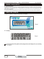
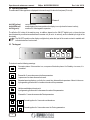
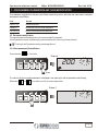
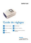
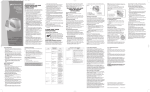
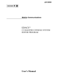
OPERATION AND MAINTENANCE MANUAL
line
alarm
on
on/off
Prg
Sel
alarm
enter
Clear
EMIpro
MICROPROCESSOR
Operation and maintenance manual
EMIpro MICROPROCESSOR
Rev. 0 dtd 02/’02
CONTENTS
1.1
GENERAL CHARACTERISTICS
General description
Page 2
Page 2
2.1
2.2
2.3
2.4
2.5
EMIPRO USER INTERFACE
The display
Operating indicators
The keypad
I/O Card (input/output)
Meaning of the inputs and outputs
Page 2
Page 2
Page 4
Page 4
Page 5
Page 5
1
2
3
PROGRAMMING PARAMETERS AND THEIR MODIFICATION
3.1 Parameters
3.2 Parameters modification
3.2.1 Direct parameters( D) modification
Page 7
Page 7
Page 7
Page 7
4
DESCRIPTION AND CONFIGURATION OF THE PARAMETERS
Page 9
5
CLOCK, TIME BANDS AND ALARM LOG
Clock
Time display
Time setting
Time bands
Copying the time bands
Alarm log
Display alarm log
Alarm log exit
Page 14
Page 14
Page 14
Page 14
Page 15
Page 15
Page 15
Page 15
Page 16
6
CONNECTION OF A SERIES OF UNITS
Page 16
7
SERIAL CARD RS 485
Page 16
ALARMS AND SIGNALS
Table of alarms
Alarm signals and description
Machine shut-down signals
Page 17
Page 18
Page 19
Page 21
5.1
5.1.1
5.1.2
5.2
5.2.1
5.3
5.3.1
5.3.2
8
8.1
8.2
8.3
1
Operation and maintenance manual
EMIpro MICROPROCESSOR
Rev. 0 dtd 02/’02
1 - GENERAL CHARACTERISTICS
1.1 General description
The EMIpro is an electronic control for the complete management of precision air-conditioners, both in direct expansion
versions (with 1 or 2 compressors), with 1 or 2 heating elements or with batteries (valve on the heating battery and/or
valve on the cooling battery).
The control also allows the management of a humidifier and dehumidification with various pre-settable configurations.
2 - EMIPRO USER INTERFACE
The EMIPRO is made up of a display and a power board, see Picture 2.
Picture 1
2.1 The display
Picture 2
Picture 2 illustrates all the symbols and the messages shown on the display; this occurs on starting
the regulator.
2
Operation and maintenance manual
EMIpro MICROPROCESSOR
Rev. 0 dtd 02/’02
8.8:8.8 Ambient temperature, when programming it displays the value of the parameters
°C - °F
88
% H
Temperature unit of measure: degrees Centigrade/Fahrenheit.
Ambient humidity, when programming it displays the no. of the parameters
Relative humidity unit of measure.
Buzzer active.
Hour counter limit exceeded.
OFF status from time bands.
A
ON OFF
Time bands active.
External contact status:
- ON machine enabled;
- OFF machine in stand-by.
Indicates that the value displayed is the temperature (without this symbol the Set-point is displayed)
Time band selected.
Dehumidification active.
Ventilation active (
1 2
1 2
fan speed compared to maximum speed)
Cooling active:
- number (1 o 2) cooling actuators ( opening cooling valve, or in shelter mode, opening free cooling
damper).
Heating active:
- number (1 o 2) heating actuators.
- % opening valve.
Humidification active( steam production compared to maximum production).
Programming phase.
- Password setting;
- Parameter modification blocked.
8
Day of the week (in clock mode)
- Clock display;
- Clock Set-up.
3
Operation and maintenance manual
EMIpro MICROPROCESSOR
Rev. 0 dtd 02/’02
2.2 Operating indicators
The main states of the regulator are displayed to the user through 3 Led on the front panel (Picture 3).
line
alarm
on
Picture 3
led LINE (yellow):
led ALARM (red):
led ON (green):
control powered;
machine alarm (the siren symbol on the display is on only when the buzzer is active);
machine ON from keypad or supervisor.
The effective ON status of the machine may, in addition, depend on the ON-OFF digital input, on the active time
band,the stand-by condition transmitted from the master unit (for units in network), and is indicated by the light of the
fan symbol.
The ON-OFF symbols on the display are lighted only when the input of the remote contact is enabled and i
indicate the status of such contact.
2.3 The keypad
line
alarm
on
on/off
Prg
Sel
alarm
enter
Clear
Picture 4
The buttons have the following meanings:
on/off
Commutes status: if the machine is on, one press of the button places it in Standby; vice-versa, it is
re-enabled.
alarm
Pressed for 5 seconds accesses the User parameters.
In presence of an alarm silences the buzzer.
Repeated pressing displays, cyclically: the current time, date and the temperature of the air in the room.
In programming phase scrolls or increases the value of the parameters.
Held pressed displays the set-point.
In programming phase scrolls or decreases the value of the parameters
enter
Pressed for 5 seconds accesses the Direct parameters.
+
alarm
4
+
Pressed together for 2 seconds reset the alarms.
enter Pressed together for 2 seconds access the Factory parameters.
Operation and maintenance manual
EMIpro MICROPROCESSOR
Rev. 0 dtd 02/’02
2.4 I/O Card (Input/Output)
Picture 5 depicts the I/O Card.
The I/O Card shows following components:
- Molex connectors (1 - 2 - 3), for carry out the main connections;
- male connector (4),for unloading or copying data;
- prearranged housing (5)for the clock board memory (optional);
- prearranged housing (6) for the serial card RS 485 (optional);
- jumper (7)for hardware selection of probe B3 (4÷20 mA/ 0÷1 Vdc), with default 0÷1 Vdc;
- protection fuse (8) of 800 mA.
clock opz.
key
serial RS485 opz.
4
5
6
Rx/Tx+
Rx/TxGND
4÷20mA
jumper
B3 selection
0÷1Vdc
7
8
1
2
3
Picture 5
800 mA fuse
2.5 Meaning of the inputs and outputs
Following table shows the meaning of the inputs and outputs according to the selected machine.
UV=
UV warm/cold=
ED=
Shelter=
heat and cool coils locker;
one coil for operating heat and cool locker;
direct expansion locker;
complete locker with condenser but without humidifier.
The values found between brackets are parameters that can influence the meaning of the input/output examined.
5
Operation and maintenance manual
EMIpro MICROPROCESSOR
Rev. 0 dtd 02/’02
Table 1 - I/O Inputs and outputs
Digital inputs - Connector 2
ID6
ID7
ID8
ID9
UV
On/Off remote (HE=1)
Flow gauge
Filter dirty
Heating elements safety
External alarm/input for
rotation of more units (Pb,
H2, HA)
Humidifier alarm (H8=1)
Water flow alarm(PF=1)
UV warm/cold
On/Off remote (HE=1)
Flow gauge
Filter dirty
Heating elements safety
External alarm/input for
rotation of more units (Pb,
H2, HA)
Humidifier alarm (H8=1)
Summer-winter
Water flow alarm(PF=1)
ID10
Fan thermal
Fan thermal
ID1
ID2
ID3
ID4
ID5
ED
On/Off remote (HE=1)
Flow gauge
Filter dirty
Heating elements safety
External alarm/input for
rotation of more units (Pb,
H2, HA)
Humidifier alarm (H8=1)
High pressure C1
Low pressure C1
High pressure C2
Compressor thermal (H5)
Low pressure C2
Fan thermal (H5)
Shelter
On/Off remote (HE=1)
Flow gauge
Filter dirty
Heating elements safety
External alarm/input for
rotation of more units (Pb,
H2, HA)
Humidifier alarm (H8=1)
High pressure C1
Low pressure C1
Compressor thermal
Shelter
Return temperature
External air temperature for
free cooling (/1, Hc)
Fan thermal
Analog inputs - Connector 2
B1
B2
UV
Return temperature
External air temperature for
compensation (/1, Hc)
UV warm/cold
Return temperature
External air temperature for
compensation (/1, Hc)
B3
Ambient humidity (/2, Hd)
Ambient humidity (/2, Hd)
ED
Return temperature
External air temperature for
compensation (/1, Hc)
Condensation control (/1, Hc,
HB)
Ambient humidity (/2, Hd)
B4
Supply temperature (/3=1)
Supply temperature (/3=1)
Supply temperature (/3=1)
Condensation pressure
(/2, Hd, Hb)
Supply temperature (/3=1)
ED
Compressor 1 (H5)
Shelter
Compressor
Compressor 2 (H5)
Heating element
Heating element 1 (H6)
Heating element 2 (H6)
Supply fan 1
Damper opens (/2, Hc)
Damper On/Off
Camper closes (/2, Hc)
Supply fan 1
Digital outputs to SSR - Connector 1
Out1
UV
Cooling valve opening (H5)
Out2
Cooling valve closing (H5)
Out3
Heating valve opening (H5)
UV warm/cold
Cooling/heating valve
opening (H1, H5)
Cooling/heating valve closing
(H1, H5)
Heating element 1 (H6)
Out4
Out5
Heating valve closing (H6)
Supply fan 1
Heating element 2 (H6)
Supply fan 1
Digital outputs to relay - Connector 3
Out6
Out7
UV
Alarm (HF)
Dehumidification/humidific.
(HA)
Alarm(HA)
Rotation (H2)
Supply fan 2 (HA=6,7)
UV warm/cold
Alarm (HF)
Dehumidification/humidific.
(HA)
Alarm(HA)
Rotation (H2)
Supply fan 2 (HA=6,7)
ED
Alarm (HF)
Dehumidification/humidific.
(HA)
Alarm(HA)
Rotation (H2)
Supply fan 2 (HA=6,7)
Shelter
Alarm (HF)
UV warm/cold
Humidifier control (/2, H8)
Supply fan (Hb)
ED
Humidifier control (/2, H8)
Supply/condensation fan
(/1, /2, Hb, Hc)
Shelter
Damper output (/2, Hc)
Condensation fan
(/1, /2, Hb, Hc)
Alarm(HA)
Rotation (H2)
Supply fan 2 (HA=6,7)
Analog outputs - Connector 1
UV
Humidifier control (/2, H8)
Supply fan (Hb)
Y1
Y2
6
Operation and maintenance manual
EMIpro MICROPROCESSOR
Rev. 0 dtd 02/’02
3 - PROGRAMMING PARAMETERS AND THEIR MODIFICATION
3.1 Parameters
The parameters are divided into 3 levels, each of them contains the previous, which the user can access to customise
the operation of the EMIpro.
Livel
Access
DIRECT (D)
Immediate access
USER (U)
Access with Service Center password
FACTORY (F)
Access with manufacturer password
3.2 Parameters modification
This manual presents Informations how to access and modfy D parameters.
U and F parameters can be modified only by an authorised Service Center or by the manufacturer.
A wrong U and F parameters setting can damage the unit.
3.2.1 Direct parameters (D) modification
enter
Press the button
on/off
for 5 seconds.
Picture 6
Prg
Sel
alarm
enter
200
1
Clear
5 sec.
The value of the first accessible parameter is displayed in the upper right, with the parameter code flashing.
With button
and
it is possibile to scroll the various parameters.
Picture 7
on/off
Prg
Sel
alarm
enter
1
1
Clear
7
Operation and maintenance manual
EMIpro MICROPROCESSOR
Rev. 0 dtd 02/’02
enter
Once having entered any level of parameters, one pressing of the
Parameter selected, while the
and
button displays the value, flashing, of the
buttons can be used to modify such value.
Picture 8
on/off
Prg
Sel
alarm
enter
1
1
Clear
Press again
Then, using the
enter
to confirm the new value.
and
buttons, scroll the parameters menu, repeating the previous steps for each parameter
to be modified.
Press the
alarm
button, on the other hand, to store the modifications made.
During all phases of setting the parameters the open book symbol
on the other hand, when setting the password, a lock
is displayed in the lower left of the display,
also appears, confirming the presence of a "block".
The presence of parameters in the various family is subject to the value of some of them:
1)
2)
3)
presence of external air probe;
presence of humidity probe;
presence of supply air probe.
8
Operation and maintenance manual
EMIpro MICROPROCESSOR
Rev. 0 dtd 02/’02
4 - DESCRIPTION AND CONFIGURATION OF THE PARAMETERS
/
Probes
1
Type
Min.
Max.
U.o.M.
Default
Presence external air probe
0 = absent
1 = NTC Carel
F
0
1
flag
0
Type of humidity/pressure/temperature probe B3
0 = absent
1 = 0-1Vdc or 0-20mA
2 = 4-20mA
F
0
2
flag
0
Presence supply air B4
0 = absent
1 = NTC Carel (enable corresponding alarm)
F
0
1
flag
0
4
Value of humidity/pressure at 0 mA, 4mA or 0Vdc
F
0
/5
5
Value of humidity/pressure at 20mA 0r 1Vdc
F
/4
100
6
Calibration probe B1
U
7
Calibration probe B2
-6.0
-10.8
-6.0
-10.8
6.0
10.8
6.0
10.8
8
Calibration probe B3
-10.0
10.0
9
Calibration probe B4
U
A
Digital filter
U
-6.0
-10.8
1
6.0
10.8
15
%rH
bar
°C
°F
-
b
Input limit
U
1
15
-
8
c
Unit of measure
0=°C
1=°F
U
0
1
flag
0
2
3
U
U
%rH
bar
%rH
bar
°C
°F
°C
°F
Value
0
100
0.0
0.0
0.0
0.0
4
9
Operation and maintenance manual
EMIpro MICROPROCESSOR
r Regulator
Rev. 0 dtd 02/’02
Type
Min.
Max.
U.o.M.
Default
rb
11.0
19.8
11.0
19.8
20.0
36.0
rd
°C/°F
°C
°F
°C
°F
°C
°F
%rH
20.0
1
2
Temperature Set Point (summer)
D
Cooling differential
D
3
Heating differential
D
4
Temperature dead zone
D
5
Humidity Set Point
D
rA
0.1
0.1
0.1
0.1
0.1
0.1
rc
6
7
Humidification differential
Dehumidification differential
D
D
1
1
20
20
%rH
%rH
4
3
8
Humidity dead zone
D
0
20
%rH
2
D
rA
-20
-4
rb
18.0
9
3.0
2.0
1.0
50
b
Maximum temperature set point (also for
compensation)
U
rA
60
140
°C/°F
°C
°F
°C
°F
c
d
Minimum humidity set point
Maximum humidity set point
U
U
0
rc
rd
100
%rH
%rH
0
100
U
0
1
flag
0
U
10
3600
s
600
U
2.0
60
140
60
140
30
54
30
86
-
0.5
Temperature Set Point (winter)
A Minimum temperature set point (also for compensation)
E Type of temperature regulation
0=Proportional
1=Proportionl and integral
F Integration time for Proportional and Integral action
G Authority (unique for summer/winter) for compensation
H Set Point compensation on temp. read by B2 (summer)
U
rb
Reading from probe B2
P Reading from probe B3
D
-2.0
-20
-4
-20
-4
0
0
-20
-4
-
D
-
-
r
t
D
-
-
°C
°F
°C
°F
°C
°F
°C
°F
°C/°F
%rH
bar
°C/°F
U
0
2
flag
U
i
Set Point compensation on temp. read by B2 (winter)
U
L
Free cooling differential
U
n
Lower supply temperature limit during free cooling
U
o
Reading from probe B4
Time band setting
0 = disabled
1 = fan on minimum with temp. monitoring
2 = On/off
10
0
50
25.0
10.0
9
5
-
0
Value
Operation and maintenance manual
EMIpro MICROPROCESSOR
c Compressor
Type
Min
Rev. 0 dtd 02/’02
Max
U.o.M.
Default
1 Minimum ON time
2 Minimum OFF time
3 Time between 2 start-ups
U
0
300
s
60
U
U
0
0
900
900
s
s
60
360
4 ON delay between the 2 compressors
5 OFF delay between the 2 compressors
U
0
300
s
30
U
0
300
s
0
F
0
1
flag
0
U
0
300
s
20
U
0
30000
h
0
D
0
30000
h
0
D
0
30000
h
0
Type
Min
Max
U.o.M.
Default
F
0
2
flag
1
F
0
F3
step
35
6 Compressor rotation
0 = disabled
1 = enabled
7 Delay compressor ON from supply fan start-up
8 Hour counter threshold for the compressor
0= disabled
9 Hour counter compressor 1
A Hour counter compressor 2
F
Fans
1
2
Fan operating mode
0 = always ON
1 = proportional speed regulation*
2 = proportional speed regulation**
Minimum Triac voltage threshold
3
Maximum Triac voltage threshold
F
F2
100
step
75
4
Triac pulse width
F
0
15
ms
2
5
Regulation band for minimum speed or
temperature/pressure /4 bar for minimum speed in
condensation
0
0
/4
F6
U
%
°C/°F
bar
0.1
Regulation band for maximum speed or
temperature/pressure /5 bar for maximum speed in
condensation
U
F5
100
158
/5
%
°C/°F
bar
100
7
Minimum output value ( higher than F2)
U
0
F8
%
10
8
9
Maximum output value (lower than F3)
Fan hour counter threshold
0 = disabled
U
F7
100
%
100
U
0
30000
h
0
A
Supply fan hour counter
D
0
30000
h
0
b
Filter hour counter threshold
0 = disabled
U
0
30000
h
0
c
Filter hour counter
D
0
30000
h
0
d
Supply fan OFF delay
U
0
900
s
20
E
Fan pick-up time in condensation
U
0
60
s
4
6
Value
Value
* If used in condensation the fan is kept at minimum even below the value of F5.
** If used in condensation the fan is switched off below the value of F5, with an hysteresis of 0.5 bar for pressure or 1°C for temperature
11
Operation and maintenance manual
P
Alarm
1
Flow alarm delay from fan start-up
2
Flow alarm delay during operation
3
EMIpro MICROPROCESSOR
Rev. 0 dtd 02/’02
Type
Min
Max
U.o.M.
Default
U
0
250
s
20
U
0
90
s
5
Low pressure alarm delay from compressor ON
U
0
250
s
40
4
Buzzer activation
0 = OFF, 1-14= min. 15= continuous
U
0
15
min
0
5
Reset alarms (various configurations)
F
1
5
flag
1
6
Delta from effective set point for low temperature alarm
U
0
50 / 90
°C / °F
10
7
Delta from effective set point for high temperature alarm
U
0
50 / 90
°C / °F
10
8
9
Delta from set point for low humidity alarm
Delta from set point for high humidity alarm
U
U
0
0
50
50
%rH
%rH
20
20
A
Alarm delay high/low temperature/humidity on start-up
U
0
150
min
20
b
Type of management of generic alarm input ID5
0 = no alarm connected
1 = signal only alarm - automatic reset
2 = signal only alarm - manual reset
3 = serious alarm - automatic reset
4 = serious alarm - manual reset
5 = serious alarm - automatic reset also active in
stand-by
6 = serious alarm - manual reset also active in
stand-by
Generic alarm delay
U
0
6
flag
1
U
0
250
s
60
0
20 / 36
°C / °F
3
c
d
Return-supply temp. difference for supply temp. alarm
U
E
Imput ID4 selection
U
0
1
flag
0
U
U
0
0
1
1
flag
flag
0
0
Type
Min
Max
U.o.M.
F Imput ID9 selection
G High temperature pre-alarm enabled
H
General
1
Machine model
0 = ED unit
1 = UV unit
2 = UV unit (Heat/Cold)
3 = shelter
F
0
3
flag
0
No. of machines in rotation
0 = stand-alone machine
1 = 1 unit (master)
2 = 2 units.......6= 6 units
U
0
6
flag
0
3
Address of unit in rotation
U
1
6
-
1
4
Rotation time between a series of units
0 = test mode(rotation mode 2 minute)
U
0
250
h
0
2
12
Default
Value
Value
Operation and maintenance manual
H
EMIpro MICROPROCESSOR
General
Rev. 0 dtd 02/’02
Type
Min
Max
U.o.M.
Default
5 Operating mode of the 2 “cool” outputs
1 = 1 compressor
2 = compressors on 2 circuits
3 = three-point valve
4 = 2 compressors in binary parallel
5 = 2 compressors in tandem (50+50%)
F
1
5
flag
1
6 Operating mode of the 2 “heat” outputs
0 = no heating element
1 = 1 heating element
2 = 2 heating elements
3 = three-point valve
4 = 2 heating elements in binary
F
0
4
flag
1
7 3P valve or damper excursion time
8 Presence of humidifier
F
F
0
0
600
1
s
flag
150
0
9 Type of dehumidification
0 = comp. 1 ON
1 = comp. 2 ON
2 = two comp. ON
3 = capacity-controlled cooling ramp
4 = fan speed reduction
5 = action 4+0
6 = action 4+1
7 = action 4+2
8 = action 4+3
9 = no action
F
0
9
flag
0
A Function of the dehumidification/humidification relay
0= energised in dehumidification
1 = de-energised in dehumidification
2 = relay for non-serious alarms (follows logic of
parameter HF)
3 = output for rotation control
4 = energised in humidification
5 = de-energised in humidification
6 = fan 2 ON in dehumidification
7 = fan 2 OFF in dehumidification
F
0
5
flag
0
b Function of output Y2 (phase-cut)
0 = supply fan speed control
1 = condensation fan speed control using B3
2 = condensation fan speed control using B2
F
0
2
flag
0
c Function of probe B2
0 = compensation
1 = free-cooling using 0-10V
2 = free-cooling using Out3-Out4
3 = free-cooling ON/OFF with Out3
4 = condensation control
F
0
3
flag
0
Value
13
Operation and maintenance manual
H
EMIpro MICROPROCESSOR
General
Rev. 0 dtd 02/’02
Type
Min
Max
U.o.M.
Default
d Function of probe B3
0 = humidity control
1 = condensation control
F
0
1
flag
0
E ON/OFF digital input
0 = absent
1 = present
U
0
1
flag
0
F Alarm relay logic
0 = de-energised in alarm for all alarms
1 = energised in alarm for all alarms
2 = de-energised in alarm only for serious alarms
3 = energised in alarm only for serious alarms
U
0
3
flag
0
G Delay on start-up
U
0
300
s
0
H USER password
U
0
200
-
22
i
U
0
1
flag
0
L Parameter sets
F
0
3
flag
0
n Select data shown on display
0= probes B1, B3 (if present)
1= temperature. and humid. set-point (if present)
2= day and time (if clock present)
U
0
2
flag
0
o Supervisor network serial address
P Supervisor serial baudrate
1= 1200, 2= 2400, 3= 4800, 4= 9600, 5=19200 Baud
U
U
1
1
200
5
flag
1
5
r
D
-
-
-
1.3
Block parameter modifications (displayed by lock)
0 = no block
Software version
Value
5 - CLOCK, TIME BANDS AND ALARM LOG
Functions enabled only with the clock board memory installed.
5.1 Clock
5.1.1 Time display
Pressing the
button displays the current time and date.
Pressing the button once displays the time and the day of the week (1= Monday, 2= Tuesday, ..., 7= Sunday); pressing it
again displays the date in the format day-month-year.
5.1.2 Time setting
First press the
on/off
button (keeping it pressed) and then the
Prg
Sel
alarm
enter
on/off
Prg
Sel
alarm
enter
Clear
2
The minutes will begin to flash; use the
enter
5
10:23
Picture 9
and
5 sec.
buttons to set the desired time.
button, on the other hand, to select, in order, the fields: hours - day of the week - year - month - day
of the month. At the end, press the
14
button, keeping both pressed for 5 seconds.
Clear
1
Use the
alarm
alarm
button to confirm the modifications made.
Operation and maintenance manual
EMIpro MICROPROCESSOR
Rev. 0 dtd 02/’02
5.2 Time bands
Entering the parameter rt (see USER parameter modification) allows the selection of rt= 1 or 2, enabling the time band
enter
function.
Pressing the
button displays, in sequence, with the scrolling of a segment, time bands 1, 2, 3, 4 of day 1
on/off
(Monday), ............ , time bands 1, 2, 3, 4 of day 7 (Sunday).
The buttons allow, with 10 minute steps, the start time of the selected band to be modified, while the
button
enables or disables the action of the band itself, confirmed by the messages ON/OFF on the display.
5.2.1 Copying the time bands
If the times set for the bands are also valid for the following days, these can be simply copied by pressing and holding
enter
the
button for 3 seconds.
Once the copy has been made, the following day is automatically displayed: if this too is to be copied, release the
enter
button and then press it again for a further 3 seconds.
on/off
Prg
Sel
alarm
enter
1
12:30
Picture 10
ON
Clear
3 sec.
The OFF status controlled by the time bands, displayed by the “half moon” symbol
on the display, acts according
to whether parameter rt is set to 1 or 2:
rt= 1 Sleep mode: during the Off status, the fan, works and the actuators remain off.
The machine is reactivated in the following conditions:
a) the temperature exceeds 70% of the high/low alarm threshold, returning to Sleep if the temperature falls
within 40% of the alarm delta.
on/off
rt= 2
b) the
is pressed: in this case the on status lasts until the next time band; during this period the
on/off
symbol A flashes.
the machine is in stand-by, as if the
had been pressed.
In this case too, pressing the on/off button activates the machine until the next band switching Off time.
5.3 Alarm log
In the event of an alarm the alarm code, hour, minute and data are recorded, up to a maximum of 300 signals. On
reaching the maximum number the oldest events are deleted (code 1 always indicates the most recent alarm).
5.3.1 Display alarm log
alarm
To display the list of alarms recorded, press the button
on/off
Prg
Sel
alarm
enter
Clear
on/off
, followed by the
Prg
Sel
alarm
enter
P O
1
Picture 11
Clear
1
2
The code of the last alarm event is shown, and, on repeatedly pressing
The
button.
enter
, the hour, minute and the date.
buttons scroll the alarm data.
In places where no alarm has been recorded, dashes are displayed instead of the code.
15
Operation and maintenance manual
EMIpro MICROPROCESSOR
Rev. 0 dtd 02/’02
The display includes an incremental index in the right-hand field, which identifies the current position; the hundreds
then appear in the field on the left (e.g.: “1 rES 55” indicates that a reset of the machine was performed, and the position
is 155).
1
es
55
Picture 12
5.3.2 Alarm log exit
alarm
To exit the menu Alarm log push the button
.
Exit occurs however by time-out after 60 seconds.
6 - CONNECTION OF A SERIES OF UNITS
This configuration is possible both for direct expansion units(ED) and coil unit (UV) and Shelter type.
It allows rotation of a unit placed in stand-by among a group of maximum 6 units.
If one of the working unit signal an alarm, the stand-by unit activates.
This is possible with the use of a digital input and output that send the command, by means of the “master”, enabling or
disabling the stand-by unit (the command is updated every 10 minutes).
The wiring diagram shows how all board are similar and that only during installation the connection must be carried out
with a three-pole cable between each lockers.
During the installation phase pay attention to the following three points:
1) One unit must be set as master
2) It is recommended to end the line with a resistance (RT) di 220 W /5W o di 470 W/ 4W;
3) Make sure the GO of the transformer are not place on the ground in order to prevent undesired current in the GO itself.
Set parameters H2, H3, H4, HA (see parameters table) to operate.
7 - SERIAL CARD RS 485
The use of the EMIpro unit inside a supervision network or remote
servicing RS 485 requires the optional serial card RS 485. The installation
of the serial card must be done as follows:
Picture 13
1) disconnect the EMIpro unit;
2) insert the serial card RS 485 on the prearranged connector located on
the I/O card(see picture 13);
3) proceed with the serial line connection, conforming with the indicated
polarity;
4) connect the EMIpro unit to the power supply.
The serial line must be closed by a 120 ohm - 1/4 W resistance placed
between the terminals Tx/Rx found on the card RS 485 of the unit, on the
opposite end of the network respect to the supervisor.
Set the network address of the EMIpro by means of the Ho parameter and the speed by means of the HP parameter.
16
Operation and maintenance manual
EMIpro MICROPROCESSOR
Rev. 0 dtd 02/’02
8 - ALARMS AND SIGNALS
In the event of an alarm, the machine performs the following actions:
>
>
>
activates the buzzer and display
, (if enabled and machine ON);
activates the alarm relay (according to parameters HF, HA);
displays the alarm code and switches on the corresponding red Led.
alarm
In this condition, pressing the
button silences the buzzer.
The termination of alarms with automatic reset, if no alarms with manual reset are active, brings about:
>
>
>
>
the switching off of the buzzer;
the deactivation of the alarm relay, see parameter HF;
the switching off of the red alarm Led;
the re-activation of the actuators switched off by the alarm.
Pressing the
buttons together for 2 seconds cancels the display of the alarm codes.
In the event of alarms with manual reset, pressing the
>
>
>
buttons together for 2 seconds brings about:
the deactivation of the alarm relay, see parameter HF;
the switching off of the red alarm Led;
the re-activation of the actuators switched off by the alarm.
The maintenance signals for compressors 1 and/or 2, the fan and the filter, due to the exceeding of the hour counter
thresholds, activate the symbol
on the display, the red Led, the buzzer and the alarm relay.
The alarm messages are shown cyclically in the order indicated in the following table. On termination, the display of
the percentage of humidity (if present) returns for 6 seconds.
17
Operation and maintenance manual
EMIpro MICROPROCESSOR
8.1 Table of alarm
n.
1
2
3
4
5
6
7
Code
E1
E2
E3
E4
Er: E
EE
EL
Description
probe B1
probe B2
probe B3
probe B4
Eeprom boot
Eeprom run
insufficient power
8
9
H1
H2
high pressure C1
high pressure C2
10
L1
low pressure C1
11
L2
low pressure C2
12
F1
filter dirty
13
14
15
16
FL
FA
CF
r1
flow
smoke - fire
water flow
heating elements
17
At
supply temperature
18
AH
humidifier
19
Lt
low temperature
20
21
22
23
24
HT
ht
LH
HH
tC
high temperature
high temperature pre-alarm
low humidity
high humidity
25
26
tF
t1/t2
fan thermal
fan thermal 1/2
27
AL
serious generic
28
PA
power fail
29
CL
clock
compressor thermal
30
31
n1 +
n2 +
hour counter threshold compressor 1
hour counter threshold compressor 2
32
nF +
hour counter threshold filter
33
nn +
hour counter threshold fan
18
Rev. 0 dtd 02/’02
Operation and maintenance manual
EMIpro MICROPROCESSOR
Rev. 0 dtd 02/’02
8.2 Alarm signals and description
All the alarms, except for the generic external alarm (AL), configured by parameter Pb, and the clock, are
detected only when the machine is On.
E1: ambient temperature probe(B1) failure: generated due to open or short-circuited probe. Alarm delayed by 1
minute from the instant the machine is placed ON and when the error is detected. At the moment of detection the control
is placed OFF, respecting the configured times, except for the fan.
E2: external air probe (B2) failure: generated due to open or short-circuited probe. Alarm delayed by 1 minute from
the instant the machine is placed ON and when the error is detected. At the moment of detection the corresponding
functions -compensation and free cooling are deactivated.
If probe B2 is used for condensation, the fan is forced on at maximum speed.
E3: humidity / pressure probe(B3) failure: generated due to open probe and for voltages above 1.15V, if the input is
configured as 0÷1V, or, if the input is configured as 4÷20mA, for currents below 3mA and over 23mA. Alarm delayed by
1 minute from the instant the machine is placed ON and when the error is detected.
At the moment of detection the corresponding functions are deactivated:
- humidity control (humidification, dehumidification);
- if probe B3 is used as a pressure sensor, for the control of condensation, and probe B2 is present for reading the
external air temperature, the fan is forced on at maximum speed if the temperature measured by B2>15°C. The same is
true if probe B2 is not present.
If the temperature B2² 15°C, on the other hand, the fan operates at half speed.
_
E4: supply air temperature probe(B4)
failure: generated due to open or short-circuited probe.
Alarm delayed by 1 minute from the instant the machine is placed ON and when the error is detected. At the moment of
detection the corresponding functions are deactivated: supply temperature alarm management (At), and, if free-cooling
is active with control of the supply temperature, the damper is closed.
EE: EEPROM data read/write error.
Can occur also during a reset only if it is not possible to make the correction to the secondary bank. This error does not
affect the operation of the regulator.
EL: insufficient power supply during EEPROM write
Data write error to EEPROM due to power failure or power below 13V.
H1-H2: high pressure C1-C2
Detected irrespective of the activation of the compressor, and causes its immediate switching off without waiting the
corresponding delay times. The alarm H2 is managed only if parameter H5= 2 or 4 (two independent circuits).
If condensation fan regulation is present, this is activated for 60 seconds at maximum speed before switching off.
L1-L2: low pressure C1-C2
Detected only with the compressor on, and causes its immediate switching off without waiting the corresponding delay
times.
The alarm is delayed by P3 seconds on the start-up of the compressor. If automatic reset is set, parameter P5, a
compressor restart is attempted 10 times, then the alarm is automatic reset automatically.
The alarm L2 is managed only if parameter H5= 2 or 4 (two independent circuits).
19
Operation and maintenance manual
EMIpro MICROPROCESSOR
Rev. 0 dtd 02/’02
F1: dirty filter
Signal-only alarm. No outputs are deactivated.
FL: air flow alarm
Alarm delayed by parameters P1 and P2.
The activation of this alarm causes the switching off of all of devices without waiting the delay times of the compressors
and the fan. If set for automatic reset, parameter P5, a restart of the outputs is attempted 10 times.
FA: smoke-fire alarm
This alarm can be configured using the PE=1 parameter.
If configured, it can causes the switching off of all actuators without respecting the timing. This alarm is noted with
machine in stand-by too.
CF: water flow
This alarm can be configured for UV unit only, using the PF=1 parameter.
When this alarm occurs, it causes the closing of the cooling valve.
r1: heating element thermal overload alarm
Causes the immediate switching off of the heating elements.
At: high supply temperature alarm (cooling function)
Enabled by the presence of the supply air temperature probe B4 (parameter /2) and by the setting of parameter Pd. The
alarm has a fixed delay of 2 minutes, and is activated only if the cooling actuators are on and heating actuators are off.
In particular, the conditions leading to the activation of the alarm are:
· ED: at least one compressor on and heating elements off or heating valve closed;
· UV: cooling valve open more than 50% and heating valve closed or heating elements off.
This alarm, when detected, only blocks the compressor on at that moment, while the second compressor remains
enabled.
AH: humidifier alarm
Alarm delayed by 30 seconds. If detected, the humidifier output (0÷10Vdc or relay) is deactivated.
Ht: high temperature alarm
These alarms are delayed on the start-up of the regulator (or on exiting stand-by mode) for a period equal to parameter
PA, and for 1 minute on exceeding the set threshold.
The reset occurs, if programmed as automatic, 1° C below the threshold.
In addition, exceeding the high temperature threshold causes the immediate start-up of the compressors without
waiting the corresponding delay times.
Lt: low temperature alarm
This alarm is delayed on the start-up of the regulator (or by going out of the stand-by) for a time equal to the parameter
PA and of 1 minute from the overcoming of the threshold.
If programmed as automatic, the reset occurs 1° C above the threshold.
ht: high temperature prealarm
This alarm can be configured using the PG = 1 parameter. This alarm is delayed by the start-up of the regulator (or by
going out of the stand-by) for a time equal to the parameter PA and of 1 minute from the overcoming of the threshold. If
programmed as automatic, the reset occurs 1° C below the P7/2 threshold.
LH-HH: low-high humidity alarm
These alarms are delayed on start-up (or by going out of the stand-by mode) for a period equal to parameter PA, and for
1 minute from exceeding the set threshold.
These are signal-only alarms, with an hysteresis of 1%
20
Operation and maintenance manual
EMIpro MICROPROCESSOR
Rev. 0 dtd 02/’02
tC: compressor thermal overload alarm
Immediate alarm, causes the instant switching off of the compressor.
This is managed only if parameter H5= 1 or 5 (one compressor only or two compressors in tandem).
tF: fan thermal overload alarm
Immediate alarm, causes the instant switching off of all devices without respecting the compressor delay times.
This is managed only if parameter H5= 1 or 5 (one compressor only or two compressors in tandem).
t1/t2: fan 1-2 thermal
This alarm can be configured by setting parameters HA = 6 o 7.
Immediate alarm, it causes the instantaneous shutdown of the connected output:
t1= 1 (Id2) supply fan
t2= 2 (Id4) supply fan
If both of them are ON the flow alarm is forced too turning OFF all the outputs (see description FL).
AL: generic external alarm
This alarm can be configured by setting parameters Pb and PC.
If configured as a serious alarm, it switches off all actuators without respecting the delay times.
PA: shelter power failure alarm
External power failure alarm delayed by 2 seconds.
This is generated for models configured as shelters when input ID6 is open; it causes the immediate switching off of the
compressor and the heating element.
CL: clock failure alarm
Alarm generated by the malfunctioning of the clock board.
Interrupts the time band function, and the regulator goes into ON status if even the current band provides an off
command. This event does not block the alarm log, which continues to store the signals, however with incorrect time
values.
n2: compressor 2 maintenance warning
Signal-only alarm generated when the hour counter threshold has been exceeded, displayed together with the
symbol
, see parameters c9 (compressor 1) and cA (compressor 2).
nF: filter maintenance warning
Signal-only alarm, see parameter Fc.
nn: fan maintenance warning
Signal-only alarm generated when the hour counter threshold has been exceeded, displayed together with the symbol,
see parameter FA (fan).
8.3 Machine shut-down signals
These appear in the event of internal machine malfunctions and cause its shut-down.
The code is displayed in the ambient temperature (or hour-minutes) field of the LCD display.
Er: C Checksum error during code check in Flash: the control can no longer be used.
Er: E The content of the EEPROM (parameter memory) is damaged.
A reset can be attempted by reloading the default values.
Er: L Insufficient power: Power voltage (lower than 13V) when writing the default values or during an attempt to
automatically recovery an EEPROM damaged sector.
21