1
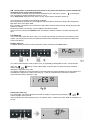
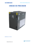
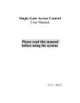
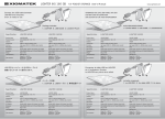
µAC Controllore per armadi di condizionamento
µAC Electronic control for air-conditioning units
LEGGI E CONSERVA
QUESTE ISTRUZIONI
READ AND SAVE
THESE INSTRUCTIONS
Manuale d’uso
User manual
Tecnologia ed Evoluzione
1. GENERAL CHARACTERISTICS
2
1.1 GENERAL DESCRIPTION
MAIN FUNCTIONS:
CONTROLLED DEVICES:
OPTIONS:
2
2
2
2
2. EMIPRO USER INTERFACE
2
2.1 THE DISPLAY
2.2 STATUS INDICATORS
MEANING OF THE LED (FIG. 3)
2.3 THE KEYPAD
3
5
5
5
3. PROGRAMMING PARAMETERS AND THEIR MODIFICATION
6
3.1 PARAMETERS
3.2 PARAMETER MODIFICATION
ACCESSING DIRECT PARAMETERS (D)
ACCESSING USER PARAMETERS (U)
6
6
6
7
4. DESCRIPTION AND CONFIGURATION OF THE PARAMETERS
8
5. CLOCK, TIME BANDS AND ALARM LOG
13
5.1 CLOCK
TIME DISPLAY
SETTING THE TIME
5.2 TIME BANDS
COPYING THE TIME BANDS
5.3 ALARM LOG
DISPLAY ALARM LOG
DELETING THE ALARM LOG
EXITING THE ALARM LOG
13
13
13
13
13
14
14
14
15
6. ALARMS AND SIGNALS
15
6.1 TABLE OF ALARM
6.2 ALARM DESCRIPTION
6.3 ALARM SIGNALS
6.4 MACHINE SHUT-DOWN SIGNALS
16
17
17
19
1
1. General characteristics
1.1 General description
The EMIPRO is an electronic control for the complete management of precision air-conditioners, both in
direct expansion versions (with 1 or 2 compressors), with 1 or 2 heating elements or with batteries (valve
on
the heating battery and/or valve on the cooling battery).
The control also allows the management of a humidifier and dehumidification with various pre-settable
configurations.
Main functions:
• Control based on the temperature and humidity of the inlet air
• Energy saving with free-cooling (Shelters) or compensation
• Dehumidification management
• Control of the supply fan speed
• Complete alarm management with log
• Rotation of a series of units
• Time bands
• Can be connected to a serial line for supervisor / telemaintenance
Controlled devices:
• 1 or 2 compressors or valve for cooling battery
• 1 or 2 heating elements or valve for heating battery
• Supply fan in ON-OFF or proportional mode
• Humidifier with proportional or ON-OFF output
• Dehumidification with ON-OFF output
• Alarm device
Options:
• RS485 serial board
• Clock board with memory for logging the alarms and time bands
• Fan control modules
• Programming key
2. EMIPRO user interface
The EMIPRO is made up of a display and a power board, see Fig. 1.
2
2.1 The display
N.B. Fig. 2 illustrates all the symbols
on starting the regulator.
and the messages shown on the display; this occurs
3
4
2.2 Status indicators
The main states of the regulator are displayed to the user through 3 LEDs on the front panel.
Meaning of the LED (Fig. 3)
Line LED (yellow): control powered
Alarm LED (red): machine alarm (the siren symbol on the display is on only when the buzzer is active)
ON LED (green): machine ON from keypad or supervisor (referred to the EEPROM variable). The
effective ON status of the machine may, in addition, depend on the ON-OFF digital input, on the active
time band,
the stand-by condition transmitted from the master unit (if a series of units is in rotation), and is indicated
by the illumination of the fan symbol.
The ON-OFF symbols on the Display are illuminated only when the input of the remote contact is
enabled and indicate the status of such contact.
2.3 The keypad
The buttons have the following meanings:
- Commutes status: if the machine is
Standby; vice-versa, it is re-enabled.
on, one press of the button places it in
- Pressed for 5 secs accesses the User parameters.
- In the presence of an alarm silences the buzzer.
- Repeated pressing displays, cyclically: the current time, date and the
temperature of the air in the room.
- In programming phase scrolls or increases the value of the parameters.
5
- Held pressed displays the set-point.
- In programming phase scrolls or decreases the value of the parameters.
- Pressed for 5 secs accesses the Direct parameters.
- In programming phase modifies the value of the selected parameter (see par.
5.2 - Parameter modification)
- Pressed together for 2 secs reset the alarms.
3. Programming parameters and their modification
3.1 Parameters
The parameters are divided into 3 levels, each of which contains
access to customise the operation of the EMIPRO.
the previous, which the user can
3.2 Parameter modification
Accessing Direct parameters (D)
The value of the first accessible parameter is displayed in the upper right, with the parameter code
flashing.
6
Accessing User parameters (U)
The number 0 is displayed and, on the left the lock symbol
procedure.
- The
the
, confirming access via password to the
buttons are used to enter the password 22 (default), which is confirmed by pressing
button.
The value of the first accessible parameter is then displayed in the upper right, with the parameter code
flashing.
The value of the first accessible parameter is then displayed in the upper right, with the parameter code
flashing.
The
buttons can be used to scroll the various parameters.
Once having entered any level of parameters, one pressing of the
flashing, of the parameter selected, while the
Press
button displays the value,
buttons can be used to modify such value.
again to temporarily store the new value.
7
Then, using the
buttons, scroll the parameters menu, repeating the previous steps for each
parameter to be modified.
Press the
button, on the other hand, to store the modifications made.
During all phases of setting the parameters the open book symbol
the display; on the other hand, when setting the password, a lock
presence of a "block".
is displayed in the lower left of
also appears, confirming the
4. Description and configuration of the parameters
/
Probes
Type
0123
Min.
Max.
U.o.M.
Def.
1
Presence external air probe
0 = absent
1 = NTC Carel
FFUU
0
1
Flag
0
2
Type of humidity/press./temp. probe B3
0 = absent
1 = 0-1Vdc or 0-20mA
2 = 4-20mA
FFFF
0
2
Flags
0
3
Presence supply air B4
0 = absent
1 = NTC Carel (enable corresp. alarm)
FFFF
0
1
Flag
0
4
Value of humidity/pressure at 0 mA, 4mA or
0Vdc
FFFF
0
/5
%rH bar
0
5
Value of humidity/pressure at 20mA 0r 1Vdc
FFFF
/4
100
%rH bar
100
6
Calibration probe B1
UFUU
-6.0
-10.8
6.0
10.8
°C
°F
0.0
7
Calibration probe B2
UFUU
-6.0
-10.8
6.0
10.8
°C
°F
0.0
8
Calibration probe B3
UFUU
-10.0
10.0
%rH bar
0.0
9
Calibration probe B4
UFUU
-6.0
-10.8
6.0
10.8
°C
°F
0.0
A
Digital filter
UFUU
1
15
-
4
b
Input limit
UFUU
1
15
-
8
c
Unit of measure (0=°C,1=°F)
UUUU
0
1
Flag
0
New
8
/
Probes
Type
0123
1
Temperature Set Point (cooling)
DDDD
2
Cooling differential
DDDD
3
Heating differential
DDDD
4
Temperature dead zone
5
6
7
Min.
Max.
U.o.M.
Def.
rA
rb
°C/°F
20.0
0.1
0.1
11.0
19.8
°C
°F
3.0
0.1
0.1
11.0
19.8
°C
°F
2.0
DDDD
0.1
0.1
11.0
19.8
°C
°F
1.0
Humidity Set Point
DDDD
rc
rd
%rH
50
Humidification differential
DDDD
1
20
%rH
4
Dehumidification differential
DDDD
1
20
%rH
3
8
Humidity dead zone
DDDD
0
20
%rH
9
Temperature Set Point (heating)
DDDD
rA
rb
°C/°F
18.0
A
Minimum temperature set point (also for U F U U
compensation)
-20
-4
rb
°C
°F
0
b
Maximum temperature set point (also for
compensation)
UFUU
rA
60
140
°C
°F
50
c
Minimum humidity set point
UFUU
0
rd
%rH
0
d
Maximum humidity set point
UFUU
rc
100
%rH
100
E
Type of temperature regulation 0=P, 1=PI
UFUU
0
1
Flag
0
F
Integration time for PI action
UFUU
10
3600
s
600
for U F U U
-2.0
2.0
H
Set Point compensation on temp. read by B2 U F U U
(cooling)
-20
-4
60
140
°C
°F
25.0
i
Set Point compensation on temp. read by B2 U F U U
(heating)
-20
-4
60
140
°C
°F
10.0
L
Free cooling differential
0
0
30
54
°C
°F
9
n
Lower supply temperature limit during free U F U U
cooling
-20
-4
30
86
°C
°F
5
o
Reading from probe B2
DDDD
°C/°F
P
Reading from probe B3
DDDD
%rH/bar
G Authority (unique
compensation
for
Cooling/heating)
UFUU
r
Reading from probe B4
DDDD
t
Time band setting
0 = disabled
1 = fan on minimum with temp. monitoring
2 = On/off
UUDD
New
0.5
°C/°F
0
2
Flags
0
9
c Compressor
Type
Min
Max
U.o.M. Def
New
0123
1
Minimum ON time
UFFF
0
300
s
60
2
Minimum OFF time
UFFF
0
900
s
60
3
Time between 2 start-ups
UFFF
0
900
s
360
4
ON delay between the 2 compressors
UFFF
0
300
s
30
5
OFF delay between the 2 compressors
UFFF
0
300
s
0
6
Compressor rotation
0 = disabled
1 = enabled
FFFF
0
1
flag
0
7
Delay comp. ON from supply fan start-up
UFUF
0
300
s
20
8
Hour counter threshold for the compressor
0= disabled
UUUU
0
30000
h
0
9
Hour counter compressor 1
DUDU
0
30000
h
0
A Hour counter compressor 2
DUDU
0
30000
h
0
F Fans
Type
0123
Min
Max
U.o.M. Def New
1
Fan operating mode
0 = always ON
1 = proportional speed regulation. If used in
condensation the fan is kept at minimum even below
the value of F5
2 = proportional speed regulation. If used in
condensation the fan is switched off below the value
of F5, with an hysteresis of 0.5 bar for pressure or
1°C for temperature
FFFF
0
2
2
Minimum Triac voltage threshold
FFFF
0
F4
step
35
3
Maximum Triac voltage threshold
FFFF
F3
100
step
75
4
Triac pulse width
FFFF
0
15
ms
2
5
% regulation band for minimum speed or
temperature/pressure /4 bar for minimum speed in
condensation
UFUF
0
0
/4
F6
%
°C/°F
bar
0.1
6
% regulation band for maximum speed or
temperature/pressure /5 bar for maximum speed in
condensation
UFUF
F5
100
158
/5
%
°C/°F
bar
100
7
Minimum output value
UFUF
0
F8
%
10
flags
1
8
Maximum output value
UFUF
F7
100
%
100
9
Fan hour counter threshold
0 = disabled
UUUU
0
30000
h
0
A
Supply fan hour counter
DUDU
0
30000
h
0
b
Filter hour counter threshold
0 = disabled
UUUU
0
30000
h
0
c
Filter hour counter
DUDU
0
30000
h
0
d
Supply fan OFF delay
UFUF
0
900
s
20
E
Fan pick-up time in condensation
UFFF
0
60
s
4
10
P Alarm
Type
0123
Min
Max
U.M. Def
1
Flow alarm delay from fan start-up
UFFF
0
250
s
20
2
Flow alarm delay during operation
UFFF
0
90
s
5
3
Low pressure alarm delay from compressor ON
UFFF
0
250
s
40
4
Buzzer activation
0 = OFF, 1-14= min. 15= continuous
UUUU
0
15
min
0
5
Reset alarms (various configurations)
FFFF
1
5
flag
1
6
Delta from effective set point for low temperature
alarm
UFUU
0
50 90
°C °F
10
7
Delta from effective set point for high temperature
alarm
UFUU
0
50 90 °F
°C
10
8
Delta from set point for low humidity alarm
UFUU
0
50
%rH
20
9
Delta from set point for high humidity alarm
UFUU
0
50
%rH
20
A
Alarm delay high/low temperature/humidity on
start-up
UUUU
0
150
min
20
b
Type of management of generic alarm input ID5
0 = no alarm connected
1 = signal only alarm - automatic reset
2 = signal only alarm - manual reset
3 = serious alarm - automatic reset
4 = serious alarm - manual reset
5 = serious alarm - automatic reset also active in
stand-by
6 = serious alarm - manual reset also active in
stand-by
UFUF
0
6
flag
1
c
Generic alarm delay
UUUF
0
250
s
60
d
Return-supply temp. difference for supply temp.
alarm
UFFF
0
20 36
°C °F
3
Type
0123
Min
Max
U.M.
Def
H General
HL=
1
Machine model
0 = ED unit
1 = CW unit
2 = CW unit (H/C)
3 = shelter
FFFF
0
3
flags
0
2
No. of machines in rotation
0 = stand-alone machine
1 = 1 unit (master)
2 = 2 units.......6= 6 units
UUUU
0
6
flags
0
3
Address of unit in rotation
UUUU
1
6
-
1
4
Rotation time between a series of units
0 = test mode t=2 min.
UUUU
0
250
h
0
5
Operating mode of the 2 “cool” outputs
1 = 1 compressor
2 = compressors on 2 circuits
3 = three-point valve
4 = 2 compressors in binary parallel
5 = 2 compressors in tandem (50+50%)
FFFF
1
5
flags
1
New
New
11
0
4
flags
1
FFFF
0
FFFF
0
600
s
150
1
flag
0
FFFF
0
9
flags
0
Function of the dehumidification/humidification relay
0= energised in dehumidification
1 = de-energised in dehumidification
2 = relay for non-serious alarms (follows logic of
parameter HF)
3 = output for rotation control
4 = energised in humidification
5 = de-energised in humidification
FFFF
0
5
flags
0
B
Function of output Y2 (phase-cut)
0 = supply fan speed control
1 = condensation fan speed control using B3
2 = condensation fan speed control using B2
FFFF
0
2
flags
0
c
Function of probe B2
0 = compensation
1 = free-cooling using 0-10V
2 = free-cooling using Out3-Out4
3 = free-cooling ON/OFF with Out3
4 = condensation control
FFFF
0
3
flag
0
d
Function of probe B3
0 = humidity control
1 = condensation control
FFFF
0
1
flag
0
E
ON/OFF digital input
0 = absent
1 = present
UUUU
0
1
flag
0
F
Alarm relay logic
0 = de-energised in alarm for all alarms
1 = energised in alarm for all alarms
2 = de-energised in alarm only for serious alarms
3 = energised in alarm only for serious alarms
UUUF
0
3
flags
0
G
Delay on start-up
UUUU
0
300
s
0
H
USER password
UUUU
0
200
-
22
i
Block parameter modifications (displayed by lock)
0 = no block
UUUU
0
1
flag
0
L
Parameter sets
FFFF
0
3
flags
0
n
Select data shown on display
0= probes B1, B3 (if present)
1= temperature. and humid. set-point (if present)
2= day and time (if clock present)
UFUF
0
2
flags
0
6
Operating mode of the 2 “heat” outputs
0 = no heating element
1 = 1 heating element
2 = 2 heating elements
3 = three-point valve
4 = 2 heating elements in binary
7
3P valve or damper excursion time
8
Presence of humidifier
9
Type of dehumidification
0 = comp. 1 ON
1 = comp. 2 ON
2 = two comp. ON
3 = capacity-controlled cooling ramp
4 = fan speed reduction
5 = action 4+0
6 = action 4+1
7 = action 4+2
8 = action 4+3
9 = no action
A
FFFF
12
o
Supervisor network serial address
UUUU
1
200
-
1
P
Supervisor serial baudrate
1= 1200, 2= 2400, 3= 4800, 4= 9600, 5=19200
Baud
UUUU
1
5
flags
5
r
Software version
DDDD
1.1
5. Clock, time bands and alarm log
Functions enabled only with the clock board memory installed.
5.1 Clock
Time display
Pressing the
button displays the current time and date.
Pressing the button once displays the time and the day of the week (1= Monday, 2= Tuesday, ..., 7=
Sunday); pressing it again displays the date in the format day-month-year.
Setting the time
First press the
button (keeping it pressed) and then the Prg button,
keeping both pressed for 5 seconds.
The minutes will begin to flash; use the
buttons to set the desired time. Use the Sel button,
on the other hand, to select, in order, the fields: hours - day of the week - year - month - day of the month.
At the end, press the Prg button to confirm the modifications made.
5.2 Time bands
Entering the parameter rt (see USER parameter modification) allows the selection of rt= 1 or 2, enabling
the time band function.
Pressing the Sel button displays, in sequence, with the scrolling of a segment, time bands 1, 2, 3, 4 of
day 1 (Monday), ............ , time bands 1, 2, 3, 4 of day 7 (Sunday). The
buttons allow, with
10 minute steps, the start time of the selected band to be modified, while the ON/OFF button enables or
disables the action of the band itself, confirmed by the messages ON/OFF on the display.
Copying the time bands
If the times set for the bands are also valid for the following days, these can be simply copied by pressing
and holding the Sel button for 3 seconds.
Once the copy has been made, the following day is automatically displayed: if this too is to be copied,
release the Sel button and then press it again for a further 3 seconds.
The operating mode controlled by the time bands is indicated by the symbol
on the display.
13
N.B. The ON status controlled by the time bands is only valid if the machine is first activated from
the keypad or the remote input (if enabled).
The OFF status controlled by the time bands, displayed by the “half moon” symbol
on the display,
acts according to whether parameter rt is set to 1 or 2:
rt= 1, Sleep mode: during the OFF status, the fan, works and the actuators remain off.
The machine is reactivated in the following conditions:
a) the temperature exceeds 70% of the high/low alarm threshold, returning to Sleep if the temperature
falls within 40% of the alarm delta.
b) the ON/OFF is pressed: in this case the on status lasts until the next time band; during this period the
symbol “A” flashes.
rt= 2: the machine is in stand-by, as if the ON/OFF had been pressed.
In this case too, pressing the ON/OFF button activates the machine until the next band switching OFF
time.
5.3 Alarm log
In the event of an alarm the alarm code, hour, minute and data are recorded, up to a maximum of 300
signals. On reaching the maximum number the oldest events are deleted (code 1 always indicates the
most recent alarm).
Display alarm log
To display the list of alarms recorded, press the button, followed by the Alarm button.
The code of the last alarm event is shown, and, on repeatedly pressing Sel, the hour, minute and the
date. The
buttons scroll the alarm data. In places where no alarm has been recorded,
dashes are
displayed in the place of the code.
The display includes an incremental index in the right-hand field, which identifies the current position; the
hundreds then appear in the field on the left (e.g.: “1 rES 55” indicates that a reset of the machine
was performed, and the position is 155).
Deleting the alarm log
The entire alarm log can be deleted from within the display of log itself, by pressing the
buttons together for 5 seconds.
At this point the FACTORY password (177) is required, which, confirmed by enter, leads to the deletion of
the log.
14
This operation re-initialises the clock board EEPROM and must be performed when installing the board
itself.
The alarm codes displayed are those reported in the table in the chap-ter on the alarms; in addition, other
special codes have been included to signal the following events:
Exiting the alarm log
To exit the alarm log menu, press the Alarm button.
The menu is exited in any case by time-out, after 60 seconds.
6. Alarms and signals
In the event of an alarm, the machine performs the following actions:
• activates the buzzer and display , (if enabled and machine ON);
• activates the alarm relay (according to parameters HF, HA);
• displays the alarm code and switches on the corresponding red LED.
In this condition, pressing the alarm button silences the buzzer.
The termination of alarms with automatic reset, if no alarms with manual reset are active, brings about:
• the switching off of the buzzer;
• the deactivation of the alarm relay, see parameter HF;
• the switching off of the red alarm LED;
• the re-activation of the actuators switched off by the alarm.
Pressing the
buttons together for 2 seconds cancels the display of the alarm codes.
In the event of alarms with manual reset, pressing the
buttons together for 2 seconds
brings about:
• the deactivation of the alarm relay, see parameter HF;
• the switching off of the red alarm LED;
• the re-activation of the actuators switched off by the alarm.
The maintenance signals for compressors 1 and/or 2, the fan and the filter, due to the exceeding of the
hour counter thresholds, activate the symbol
on the display, the red LED, the buzzer and the alarm
relay.
The alarm messages are shown cyclically in the order indicated in the following table. On termination, the
display of the percentage of humidity (if present) returns for 6 seconds.
15
6.1 Table of alarm
n.
Cod.
Description
Delay
Reset
Buzz.
Alarm
C1
C2
R1
R2
Sys/ON
Fan
Hum.
Dehum
1
E1
probe B1
1 min
P5
ON
ON
-
-
OFF
OFF
2
E2
probe B2
1 min
P5
ON
ON
-
-
-
3
E3
probe B3
1 min
P5
ON
ON
-
-
-
-
-
-
-
-
-
-
-
OFF
OFF
4
E4
probe B4
1 min
P5
ON
ON
-
-
-
-
-
-
-
-
5
Er: E
EEPROM boot
imm.
auto
-
-
OFF
OFF
OFF
OFF
6
EE
EEPROM run
imm.
auto
ON
ON
-
-
-
-
-
-
-
-
7
EL
insuff. power
imm.
auto
ON
ON
-
-
-
-
-
-
-
-
8
H1
high press C1
imm.
man
ON
ON
OFF
-
-
-
-
-
-
-
9
H2
high press C2
imm.
man
ON
ON
-
OFF
-
-
-
-
-
-
10
L1
low press C1
P3
P5
ON
ON
OFF
-
-
-
-
-
-
-
11
L2
low press C2
P3
P5
ON
ON
-
OFF
-
-
-
-
-
-
12
F1
filter dirty
imm.
P5
ON
ON
-
-
-
-
-
-
-
-
13
FL
flow
P1/2
P5
ON
ON
OFF
OFF
OFF
OFF
OFF OFF OFF OFF
OFF OFF OFF OFF
OFF OFF OFF OFF
14
r1
heating elements
Imm.
man
ON
ON
15
At
supply temp
2min
P5
ON
ON
-
16
AH
humidifier
30 s
P5
ON
ON
-
17
Lt
low temp.
PA
P5
ON
ON
-
-
-
-
-
-
-
-
-
-
-
-
-
-
-
-
OFF
-
-
-
-
-
-
-
-
-
OFF OFF
OFF OFF
18
Ht
high temp.
PA
P5
ON
ON
ON
ON
-
-
-
-
-
-
19
LH
low humid.
PA
P5
ON
ON
-
-
-
-
-
-
-
-
20
HH
high humid.
PA
P5
ON
ON
-
-
-
-
-
-
-
-
21
tC
comp. thermal
imm.
P5
ON
ON
OFF
-
-
-
-
-
-
-
22
Tf
fan thermal
imm.
P5
ON
ON
OFF OFF OFF OFF
OFF
OFF
OFF
OFF
23
AL
serious generic
PC
Pb
ON
ON
OFF OFF OFF OFF
OFF
OFF
OFF
OFF
24
PA
power fail
2s
auto
ON
ON
OFF
-
OFF
-
-
-
-
-
25
CL
clock
imm.
man
ON
ON
-
-
-
-
-
-
-
-
26
n1 +
hour counter
threshold
compressor 1
imm.
c9
ON
ON
-
-
-
-
-
-
-
-
27
n2 +
hour counter
threshold
compressor 2
imm.
cA
ON
ON
-
-
-
-
-
-
-
-
28
nf +
hour counter
threshold filter
imm.
FC
ON
ON
-
-
-
-
-
-
-
-
29
nn +
hour counter
threshold fan
imm.
FA
ON
ON
-
-
-
-
-
-
-
-
16
6.2 Alarm Description
Cod.
Description
P5= 1
P5= 2
P5= 3
P5= 4
P5= 5
E1
probe B1
auto
auto
man
auto
auto
E2
probe B2
auto
auto
man
auto
auto
E3
probe B3
auto
auto
man
auto
auto
E4
probe B4
auto
auto
man
auto
auto
EE
eeprom run
man
man
man
man
man
EL
insuff. power on EEPROM
write
man
man
man
man
man
H1
high pressure C1
man
man
man
man
man
H2
high pressure C2
man
man
man
man
man
L1
low pressure C1
man
auto
man
auto
auto
L2
low pressure C2
man
auto
man
auto
auto
F1
filter dirty
man
auto
man
man
auto
FL
flow
man
auto
man
man
man
r1
heating elements
man
man
man
man
man
At
supply temp
man
auto
man
man
man
AH
humidifier
man
auto
man
auto
auto
Lt
low temperature
man
auto
man
auto
auto
Ht
high temperature
man
auto
man
auto
auto
LH
low humidity
man
auto
man
auto
auto
HH
high humidity
man
auto
man
auto
auto
tC
comp. thermal
man
auto
man
man
auto
tF
fan thermal
man
auto
man
man
auto
AL
serious generic
Pb
Pb
Pb
Pb
Pb
PA
power fail (shelters)
auto
auto
auto
auto
auto
CL
clock
man
man
man
man
man
6.3 Alarm signals
All the alarms, except for the generic external alarm (AL), configured by parameter Pb, and the
clock, are detected only when the machine is ON.
E1: ambient temperature probe failure: generated due to open or short-circuited probe. Alarm delayed
by 1 minute from the instant the machine is placed ON and when the error is detected. At the moment
of detection the control is placed OFF, respecting the configured times, except for the fan.
E2: external air probe failure: generated due to open or short-circuited probe. Alarm delayed by 1
minute from the instant the machine is placed ON and when the error is detected. At the moment of
detection the corresponding functions -compensation and free cooling are deactivated.
If probe B2 is used for condensation, the fan is forced on at maximum speed.
E3: humidity / pressure probe failure: generated due to open probe and for voltages above 1.15V, if
the input is configured as 0÷1V, or, if the input is configured as 4÷20mA, for currents below 3mA and over
23mA. Alarm delayed by 1 minute from the instant the machine is placed ON and when the error is
detected.
At the moment of detection the corresponding functions are deactivated:
- humidity control (humidification, dehumidification);
- if probe B3 is used as a pressure sensor, for the control of condensation, and probe B2 is present for
reading the external air temperature, the fan is forced on at maximum speed if the temperature measured
by B2>15°C. The same is true if probe B2 is not present.
- If the temperature B2² 15°C, on the other hand, the fan operates at half speed.
17
E4: supply air temperature probe: generated due to open or short-circuited probe.
Alarm delayed by 1 minute from the instant the machine is placed ON
and when the error is detected. At the moment of detection the corresponding functions are deactivated:
supply temperature alarm management (At), and, if free-cooling is active with control of the supply
temperature, the damper is closed.
EE: EEPROM data read/write error.
Can occur also during a reset only if it is not possible to make the correction to the secondary bank. This
error does not affect the operation of the regulator.
EL: insufficient power supply during EEPROM write
Data write error to EEPROM due to power failure or power below 13Veff.
H1-H2: high pressure C1-C2
Detected irrespective of the activation of the compressor, and causes its immediate switching off without
waiting the corresponding delay times.
The alarm H2 is managed only if parameter H5= 2 or 4 (two independent circuits).
If condensation fan regulation is present, this is activated for 60 seconds at maximum speed before
switching off.
L1-L2: low pressure C1-C2
Detected only with the compressor on, and causes its immediate switching off without waiting the
corresponding delay times.
The alarm is delayed by P3 seconds on the start-up of the compressor. If automatic reset is set,
parameter P5, a compressor restart is attempted 10 times, then the alarm is automatic reset
automatically.
The alarm L2 is managed only if parameter H5= 2 or 4 (two independent circuits).
F1: dirty filter
Signal-only alarm. No outputs are deactivated.
FL: air flow alarm
Alarm delayed by parameters P1 and P2.
The activation of this alarm causes the switching off of all of devices without waiting the delay times of the
compressors and the fan.
If set for automatic reset, parameter P5, a restart of the outputs is attempted 10 times.
r1: heating element thermal overload alarm
Causes the immediate switching off of the heating elements.
At: high supply temperature alarm (cooling function)
Enabled by the presence of the supply air temperature probe B4 (parameter /2) and by the setting of
parameter Pd.
The alarm has a fixed delay of 2 minutes, and is activated only if the cooling actuators are on and heating
actuators are off.
In particular, the conditions leading to the activation of the alarm are:
•
ED: at least one compressor on and heating elements off or heating valve closed;
•
CW: cooling valve open more than 50% and heating valve closed or heating elements off.
This alarm, when detected, only blocks the compressor on at that moment, while the second compressor
remains enabled.
AH: humidifier alarm
Alarm delayed by 30 seconds. If detected, the humidifier output (0÷10Vdc or relay) is deactivated.
Lt: low temperature alarm
Ht: high temperature alarm
These alarms are delayed on the start-up of the regulator (or on exiting stand-by mode) for a period equal
to parameter PA, and for 1 minute on exceeding the set threshold. The reset occurs, if programmed as
automatic, 1 degree above (Lt) and 1 degree below (Ht) the threshold.
18
In addition, exceeding the high temperature threshold causes the immediate start-up of the compressors
without waiting the corresponding delay times.
LH-HH: low-high humidity alarm
These alarms are delayed on start-up (or on exiting stand-by mode) for a period equal to parameter PA,
and for 1 minute from exceeding the set threshold.
These are signal-only alarms, with an hysteresis of 1% R.H.
tC: compressor thermal overload alarm
Immediate alarm, causes the instant switching off of the compressor.
This is managed only if parameter H5= 1 or 5 (one compressor only or two compressors in tandem).
tF: fan thermal overload alarm
Immediate alarm, causes the instant switching off of all devices without respecting the compressor delay
times.
This is managed only if parameter H5= 1 or 5 (one compressor only or two compressors in tandem).
AL: generic external alarm
This alarm can be configured by setting parameters Pb and PC.
If configured as a serious alarm, it switches off all actuators without respecting the delay times.
PA: shelter power failure alarm
External power failure alarm delayed by 2 seconds.
This is generated for models configured as shelters when input ID6 is open; it causes the immediate
switching off of the compressor and the heating element.
CL: clock failure alarm
Alarm generated by the malfunctioning of the clock board.
Interrupts the time band function, and the regulator goes into ON status if even the current band provides
an off command. This event does not block the alarm log, which continues to store the signals, however
with incorrect time values.
n1: compressor 1 maintenance warning
n2: compressor 2 maintenance warning
Signal-only alarm generated when the hour counter threshold has been exceeded, displayed together
with the symbol, see parameters c9 (compressor 1) and cA (compressor 2).
nF: filter maintenance warning
nU: fan maintenance warning
n2: compressor 2 maintenance warning Signal-only alarm generated when the hour counter threshold
has been exceeded, displayed together with the symbol, see parameters FC (filters) and FA (fan).
6.4 Machine shut-down signals
These appear in the event of internal machine malfunctions and cause its shut-down.
The code is displayed in the ambient temperature (or hour-minutes) field of the LCD display.
Er: C Checksum error during code check in Flash: the control can no longer be used.
Er: E The content of the EEPROM (parameter memory) is damaged.
A reset can be attempted by reloading the default values.
Er: L Insufficient power: Power voltage < 13Veff when writing the default values or during an attempt to
automatically recovery an EEPROM damaged sector.
19