1
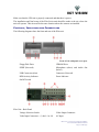
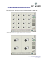
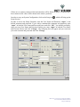
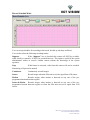
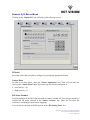
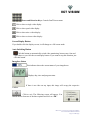
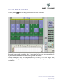
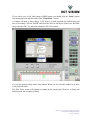
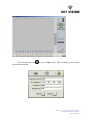
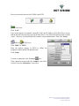
ELITE SERIES SECURE ACCESS VIDEO SURVEILLANCE USER GUIDE & INSTALLATION MANUAL April, 2003 ©2003, VCT Vision, Inc. This document, as well as the software described in it, is furnished under license and may only be used or copied in accordance with the terms of such license. The information in this document is furnished for informational use only, is subject to change without notice, and should not be construed as a commitment by VCT Vision, Inc. VCT Vision assumes no responsibility or liability for any errors or inaccuracies that may appear in this book. Except as permitted by license, no part of this publication may be reproduced, stored in a retrieval system, or transmitted, in any form or by any means, electronic, mechanical, recording, or otherwise, without the prior written permission of VCT Vision, Inc. Microsoft, Windows, Windows 95, Windows 98, Windows 2000, Windows Me, Windows XP and Windows NT are registered trademarks of Microsoft Corp. Elite Series, SAVS, VCT-E, VCT-M and VCT-R are trademarks of VCT Vision, Inc. All other name brands are the property of their respective companies. Elite Series – Secure Access Video Surveillance User Guide and Installation Manual Page 2 of 48 Pages TABLE OF CONTENTS I. About this Guide ................................................................................................................ 6 Syntax and Conventions.......................................................................................................... 6 How to Install the Elite Series System .................................................................................... 6 How Do I Operate the Elite Series System ............................................................................. 6 II. Product Overview ........................................................................................................... 7 General Information ................................................................................................................ 7 Features ................................................................................................................................... 7 Typical Applications ............................................................................................................... 8 Elite Series Primary Functions................................................................................................ 8 Digital Video Recorder ..................................................................................................................... 8 A Business Surveillance System via Internet ................................................................................... 8 An Alarm Verification System ......................................................................................................... 8 A Corporate Remote Management System....................................................................................... 9 III. Elite Series Installation ................................................................................................ 10 Unpacking the Elite Series Unit ............................................................................................ 10 Package Contents ............................................................................................................................ 10 Additional Components Required................................................................................................... 10 Before Beginning .................................................................................................................. 10 Controls, Indicators and Connections ................................................................................... 11 Power .............................................................................................................................................. 12 Monitor ........................................................................................................................................... 12 Real Time Monitor.......................................................................................................................... 12 Keyboard/Mouse............................................................................................................................. 12 Cameras .......................................................................................................................................... 12 Communications ............................................................................................................................. 13 IV. Elite Series Configuration............................................................................................ 14 Default Setup......................................................................................................................... 17 Start Mode....................................................................................................................................... 17 On Screen Display (OSD) Mode .................................................................................................... 17 Elite Series – Secure Access Video Surveillance User Guide and Installation Manual Page 3 of 48 Pages Restart Mode................................................................................................................................... 17 Watch Dog Mode............................................................................................................................ 18 Auto Switching Mode ..................................................................................................................... 18 Motion Detection (M/D) Beep Mode.............................................................................................. 18 PTZ Mode ....................................................................................................................................... 18 Display Mode.................................................................................................................................. 18 Security Check ................................................................................................................................ 18 Network Mode ................................................................................................................................ 19 Audio Device Mode........................................................................................................................ 19 Remote Port Mode .......................................................................................................................... 19 Camera Setup ........................................................................................................................ 20 Camera Select Mode ....................................................................................................................... 20 Default Setting Mode...................................................................................................................... 20 Recording Setting Mode ................................................................................................................. 21 Audio Setting Mode........................................................................................................................ 21 Event Frame Setting Mode ............................................................................................................. 21 Record Schedule Mode ................................................................................................................... 22 Digital I/O Setup Mode ......................................................................................................... 23 DI Select ......................................................................................................................................... 23 Sensor Mode ................................................................................................................................... 23 DO Select Number.......................................................................................................................... 23 Motion Setup ......................................................................................................................... 24 Select Sensitivity Mode .................................................................................................................. 24 DO Select Number.......................................................................................................................... 24 Night Motion Setup......................................................................................................................... 25 Insert Motion Detection (MD) Zone Mode..................................................................................... 25 Color/POS Setup ................................................................................................................... 26 Auto Backup.......................................................................................................................... 27 File Management................................................................................................................... 28 V. System Operation............................................................................................................... 29 Controls ................................................................................................................................. 30 Manual Recording Button............................................................................................................... 30 PTZ Control Panel .......................................................................................................................... 30 Elite Series – Secure Access Video Surveillance User Guide and Installation Manual Page 4 of 48 Pages Screen Display Button .................................................................................................................... 31 Auto Switching Button ................................................................................................................... 31 Imagebox Status.............................................................................................................................. 31 SEARCH PROGRAM MODE ............................................................................................. 32 BACKUP PROGRAM MODE ............................................................................................. 37 VI. System Operation (Remote Site)..................................................................................... 39 Introduction ........................................................................................................................... 39 Monitor Video and Control PTZ Cameras............................................................................ 42 Searching Recorded Video in the Main Elite Series System ................................................ 45 VII. Return Policy ............................................................................................................. 47 Warranties ............................................................................................................................. 47 Shipping Damage Claims...................................................................................................... 47 Elite Series – Secure Access Video Surveillance User Guide and Installation Manual Page 5 of 48 Pages I. ABOUT THIS GUIDE This Guide describes how to install, configure and troubleshoot the Elite Series Surveillance Systems, which include the Elite Series and the Elite Series Receiver Software. If the information in the README.TXT file differs from the information in this guide, follow the information in the README.TXT file on the installation CD. Version and release changes and modifications will always be accompanied by a new README.TXT file with updated information. SYNTAX AND CONVENTIONS The following tables show the syntax and conventions used throughout this Guide. When you see ATTENTION you should pay special attention to the relevant paragraph. Words in this format refer to commands in the Elite Series programs. Words in this format refer to connectors on the Elite Series unit. Notes are given in italicized format. Hyperlinks are often given within the text, and will take you to the relevant section of the Guide. HOW TO INSTALL THE ELITE SERIES SYSTEM To install the Elite Series System, you must install the Elite Series Unit at the location to be monitored, connect the cameras and communication lines and install the Elite Series Receiver Software on the Receiver PC. There are separate chapters on the Elite Series Installation, and Elite Series Configuration. HOW DO I OPERATE THE ELITE SERIES SYSTEM System operation is extremely simple, although there are several different ways of using the Elite Series system. According to your requirements, the system can be configured differently – see System Operation (Local) in Chapter V and System Operation (Remote) in Chapter VI. In the unlikely event that the system does not operate properly, you should contact our technical support. Elite Series – Secure Access Video Surveillance User Guide and Installation Manual Page 6 of 48 Pages II. PRODUCT OVERVIEW GENERAL INFORMATION The Elite Series Remote Video Surveillance System is composed of a Plug&Play unit and the Elite Series Receiver software. The system was designed and pre-configured at the factory for easy installation and operation The Elite Series unit captures real-time video images for local display (built-in multiplexer function), local recording and playback (digitally records images on HDD thus eliminating the need for VCRs/Time Lapse Recorders) and transmission to any PC equipped with the Receiver software. Additionally, the Elite Series unit has a real-time TV monitor. The Receiver is a standard PC-compatible system equipped with the Receiver software. Installation of the Receiver unit consists of merely a software installation and configuration of the network settings. This Elite Series unit is shipped with all the necessary hardware and software already installed and configured. All you need to do is connect the video cameras, power and communications. Depending on the model, there may be 4 or 16 video inputs. The four channel units are functionally identical to the 16 channel units, except that the display modes are limited to one or four images. The 16 channel units also have 9 and 16 image display modes. FEATURES Plug & Play unit High speed Intel Processor 10/100 LAN Connection Local real-time video output Up to 4 or 16 video inputs Simultaneous recording, display and transmission Alarm Inputs (optional) Local Video Recording Local Video Playback Motion Detection Remote Viewing Software Video File Management System (Local and Remote) LAN, ISDN OR PSTN Communications P/T/Z and Focus control (Remote and Local) Relay Control (Remote and Local) Time/date stamps Password protection Elite Series – Secure Access Video Surveillance User Guide and Installation Manual Page 7 of 48 Pages TYPICAL APPLICATIONS For years CCTV system operators have worked with transmission media such as coaxial cable, fiber optics and microwave. However, each of these is limited by distance and/or physical barriers and can be very expensive to install and maintain. Often, a long distance transmission system utilizing an Internet or Intranet connection is a simpler, more costeffective alternative. The necessary lines are already in service so that there is virtually no limit on where information can be sent. By simply plugging a video transmission system into a TCP/IP network (Internet/Intranet) an easy and practical video transmission can be effectively achieved between two locations anywhere in the world, as long as there is access to the network at these two locations. Typical examples are: • • • • • • • • • • Restaurants Convenience Stores Retail Stores and Supermarkets Utility Companies Fast Food Chains Car Dealerships Gated Communities Universities Banking Gas Station Chains ELITE SERIES PRIMARY FUNCTIONS Digital Video Recorder The Elite Series unit can be used simply as a Digital Video Recording System, effectively replacing a multiplexer and Time Lapse Recorder. Images can be displayed on a monitor in real time, or recorded onto HDD and recovered and played back later with the aid of a powerful Video File Management System. A Business Surveillance System via Internet The Elite Series Unit can be installed in a business office or store. By connecting into this unit, via Internet, from a PC at any remote location, the owner is able to monitor their property, business and/or employees. If the Elite Series unit is connected to a permanent IP address, it can be accessed from anywhere in the world via the Internet. Cable and DSL connections are becoming more readily available at low cost, and it is now feasible to have a high-speed, permanent Internet connection in the small business environment. An Alarm Verification System When an installed alarm system is activated, and communicates with a Security Office, it also can be connected to an Elite Series unit, and trigger a connection to any remote PC via a TCP/IP Network or modem connection. Elite Series – Secure Access Video Surveillance User Guide and Installation Manual Page 8 of 48 Pages Thus it can be programmed, for instance, to call the store owner’s PC, or to send images to the Security Company. This way, the Security Company or business owner can verify if the alarm was genuine, and what is happening at the Elite Series site. The Video Image Storage also allows verification of pre and post-alarm video, and is recorded on HDD for possible evidence. As the Elite Series Unit is small, unobtrusive, and does not require any routine maintenance, it can be concealed from the sight of any possible intruder. A Corporate Remote Management System Elite Series units can be connected on a Corporate LAN/WAN, and be accessed by any PC connected to the same network. Other units may be remote to the LAN/WAN, but be accessible via the Internet. In this way, multiple sites can be monitored by multiple PC’s, enabling the system to be used for remote management, surveillance, security and other functions. Elite Series – Secure Access Video Surveillance User Guide and Installation Manual Page 9 of 48 Pages III. ELITE SERIES INSTALLATION UNPACKING THE ELITE SERIES UNIT ATTENTION The Elite Series Unit should be removed carefully from its shipping case and inspected for any damage caused in transit. Should any damage be found, your supplier and or shipper should be advised immediately so that adequate insurance claims may be made. Package Contents The Elite Series Video Surveillance kit contains the following items: • Elite Series unit • Keyboard • Mouse • Power cable • CD-ROM containing the Receiver software and The User Guide and Installation Manual (this document). Additional Components Required Note: These components are not part of the Elite Series package. However, they are required for the surveillance system to operate. • Video camera (at least one - up to four or sixteen, depending on model) • Video cable for each camera Installation of the Elite Series surveillance system does not require any special tools. However, you need the following equipment to complete the installation: • VGA Monitor or Security Television • An Internet or Intranet connection with a registered, static IP address, or a modem connection. BEFORE BEGINNING ATTENTION Before you continue with the installation of the surveillance system, it is important that you verify the following: • The Elite Series unit should be plugged into a UPS (Uninterruptible Power Supply) unit rated 200W or higher. Note: A UPS unit is not supplied with Elite Series. The UPS will not only protect the Elite Series from power surges, but it will also supply power to the unit for a period of time in the event of a power outage. Elite Series – Secure Access Video Surveillance User Guide and Installation Manual Page 10 of 48 Pages Make sure that the UPS unit is properly connected and that there is power. The installation and final setup of the Elite Series unit should be made at the site where the unit will operate. This site must be the same location where the cameras are installed. CONTROLS, INDICATORS AND CONNECTIONS The following diagrams show the front and rear of the Elite unit. Front of Unit with panel cover open. Floppy Disk Drive CDROM Drive SPDIF (Not used) Microphone (above) and Audio Out (below) USB Connectors (four) Connector (Not used) HDD Activity Indicator Power Indicator On/Off Switch Elite Unit – Back Panel Voltage Selection Switch Video Output Connector Video Input Connectors – (1 thru’ 4 or 16) AC Input Elite Series – Secure Access Video Surveillance User Guide and Installation Manual Page 11 of 48 Pages Firewire Connector Mouse (above) and Keyboard (below) Connectors LAN/Ethernet ( above) and USB (below) VGA Connector Connectors Parallel Port Connector Digital Monitor Connector Video Output Line Out Line In Microphone Serial Port. Power The Elite Series unit should be plugged into a UPS (Uninterrupted Power Supply). ATTENTION The correct voltage should be selected on the Voltage Selection Switch before plugging the power cord of the Elite Series unit into a three-pin plug in outlet. Monitor The Elite Series may be connected to a standard analog computer monitor via the VGA connector, a digital monitor via the Digital Monitor connector or to a standard security television using composite output via Video Output. Make sure that the monitor is also connected to an adequate power supply receptacle – preferably it should also be connected to the UPS. Real Time Monitor Additionally, the Elite Series has an extra output (Video Output Connector) for a real-time video monitor. The connector for this output is located next to the Video Input Connectors. Keyboard/Mouse Connect the keyboard and mouse to the Keyboard and Mouse connectors on the rear panel of the Elite Series unit. Cameras The cameras should now be connected to the BNC connectors on the rear of the Elite Series unit. The camera positions are clearly marked next to each connector. Depending on the model being used, there are four or sixteen inputs to the Elite Series unit. If you are using less than the maximum number of cameras, it is preferable to connect them starting at position 1 and working up consecutively to the last camera position. Elite Series – Secure Access Video Surveillance User Guide and Installation Manual Page 12 of 48 Pages Communications The Elite Series can communicate over an Intranet or Internet connection from an ISDN, DSL or Cable connection with a static TCP/IP address, or over a standard modem connection. If possible, verify that the connection is operational by using a standard computer terminal. If the system is going to be connected to a corporate network or a LAN connected to the Internet, confirm with the network administrator that the connection being used for the Receiver (Remote) PC is operating properly. ATTENTION There must be a registered, static IP address assigned to the Elite Series system to connect to the unit remotely over an IP Network. Elite Series – Secure Access Video Surveillance User Guide and Installation Manual Page 13 of 48 Pages IV. ELITE SERIES CONFIGURATION Upon initial power-up, the following screen will be displayed for the 16 channel units. The four channel units will display a similar screen as shown below: Elite Series – Secure Access Video Surveillance User Guide and Installation Manual Page 14 of 48 Pages If there are no cameras connected, the main interface will be shown as above. If cameras have been connected, the video will be shown in the relative positions. In order to carry out System Configuration, click on the Setup icon Setup Screens. , which will bring up the In order to access the Setup Functions, enter the User Name and Password. “super” is the default username and password. If you wish to maintain this username and password, enter “super” in both the User Name and Password boxes and click “OK”. You should, preferably, enter your own User Name and Password. In this case, enter “super” in both the User Name and Password boxes and click “Change”. The following box will appear and you can insert your own use name and password and click “Change”. Elite Series – Secure Access Video Surveillance User Guide and Installation Manual Page 15 of 48 Pages You will have to re-enter the new username and password to gain access to the Setup screen shown below. Along the top of this screen are seven main menu buttons, for “Default Setup”, “Camera Setup”, “Digital I/O Setup”, “Motion Setup”, “Color/POS Setup”, “Auto Backup” and “File Management”. The first screen is the “Default Setup” screen, and we will now describe the various options for this screen. Elite Series – Secure Access Video Surveillance User Guide and Installation Manual Page 16 of 48 Pages DEFAULT SETUP Start Mode You may select the default mode for the monitoring screen. For the sixteen channel units, this may be a single video image, four (Quad mode), nine or sixteen video images. The selection is made in the drop-down box – 1, 4, 9 or 16. The four channel units are limited to single or quad mode (1 or 4 in drop-down box). On Screen Display (OSD) Mode You can select OSD in order to display ‘Location’, ‘Number’ and ‘Recording status’ of each camera, superimposed on each video window. The location (Front Office, Cash Register, Parking Lot for example) is entered on the “Camera Setup” screen. The following image is an example of the display with these onscreen messages. In this case, we are looking at the front office door on Camera 1 and motion has initiated the recording process. Restart Mode You can choose to automatically shut down and restart the system at selected days and times. Check the box relative to the day(s) and the time to restart the system. Note that this mode can only be executed when the system is powered up. It is not necessary to select this function if your Elite System is in use permanently. Elite Series – Secure Access Video Surveillance User Guide and Installation Manual Page 17 of 48 Pages Watch Dog Mode This is a safety function that helps you avoid being on the status of shutdown when it occurred. To select Watch Dog function, click the box and set the time. Auto Switching Mode To select Auto Switching Mode, check the “Enable Auto Switching” box, and set the number of seconds for the displayed video. This can be set from 1 to 255 seconds. The display will then automatically switch through all the video inputs in accordance with the screen display selected. For example, if there are 4 cameras connected, and the display mode is set to one, the display will switch through the four images every second. This is the same function as the switch on the main program. This will also switch the video-out signal on analog TV. Motion Detection (M/D) Beep Mode To select the Motion Detection Beep Mode, just click the box. It will automatically generate an alarm signal when motion is detected. PTZ Mode In order to activate the pan/tilt/zoom control, both locally and remotely, check the “Enable PTZ” box. If this box is selected the PTZ control panel will appear on the main display screen. If it is not selected, the PTZ control panel will not be available. You should also select the protocol being used for PTZ control as well as the PTZ port from the dropdown menus. Display Mode Select between ‘PAL’ and ‘NTSC’ according to the camera type being used. Security Check To select Security Check, check the “Activate Password Request” box. If you also require that shutdown be controlled by password, check the “Password on Shutdown” box. If there is no operator activity (either keyboard or mouse) for the time set in the “Wait” box, the password will be required to access the system. Elite Series – Secure Access Video Surveillance User Guide and Installation Manual Page 18 of 48 Pages User name and password are the same as you used for ‘LOG IN’ in the Setup Mode. Network Mode If remote access is to be allowed, the “Enable Network” box MUST be checked. Otherwise no remote access will be possible, including the search of recorded images or saving of images in the client system. You should also select the type of communication being used – LAN, ISDN or PSTN, as well as the communication configuration if appropriate. Audio Device Mode Select the audio device as appropriate from the drop-down menu. Remote Port Mode You can select the Network port number to open for the remote sites. In case of using Network protection software like Firewall, you can set this port according to your requirements. It is factory set at 1104. Elite Series – Secure Access Video Surveillance User Guide and Installation Manual Page 19 of 48 Pages CAMERA SETUP Clicking on the “Camera Setup” tab will bring up the following screen: Camera Select Mode The options can be set for all the cameras or for the cameras individually. Clicking on “A” will select all. Clicking on the “Camera Select Mode” button will select the individual camera. If you click on “A”, it automatically set “Capture Frame” and “Continuous Recording Frame” to the average frame size for every camera channel. If you want to adjust “Capture Frame” and “Continuous Recording Frame” per each camera, you should not click “A” because it will change every camera’s frame to the default rate. Default Setting Mode Check the “Enable Camera” if the selected camera is to be enabled. This will enable the other options on this screen. Also, if you selected “Camera Location” on the OSD Mode of the Default Setup page, the name entered in the “Installation Location” box, as shown below, will be displayed on the video screen while monitoring. Elite Series – Secure Access Video Surveillance User Guide and Installation Manual Page 20 of 48 Pages Recording Setting Mode The application program supports three resolutions Low (352 x 240), High (704 x 240) and Progressive (704 x 480). Note: Do not select 704 x 480 unless you use a progressive camera. You will actually record interlaced video at this resolution. To record video at 704 x 480 without interlaced video, you must use Progressive CCTV cameras. Otherwise, you should select High (704 x 240) to record videos at 704 x 48). The unit will capture video at 704 x 240 and stretch the video to 704 x 480 for playback. The default resolution is Low (352 x 240). Note that the higher the resolution, the larger the image files sizes. Consequently, the HDD usage is higher. The quality can be selected between 20 and 80, which is the inverse of the compression ratio. The higher the quality selected, the larger the file size will be. The default setting is 50. Audio Setting Mode If audio is to be used, the “Enable Audio” box should be checked. The default bit rate is 8000 Hz. This can also be increased, and there are four options. The “Audio Sensitivity” and “Recording Time” can also be selected – both can be from 1 to 255. Event Frame Setting Mode In this mode you can configure the settings for recording in the Sensor, Motion, Motion & Sensor modes. You can record up to 8 frames before and after the event triggering. The number of frames should be entered in the “Pre Frame” and “Post Frame” boxes. By using “Hold Event”, you can select the additional hold period, in seconds, when events from Sensor, Motion, and Sensor & Motion modes are triggered. Elite Series – Secure Access Video Surveillance User Guide and Installation Manual Page 21 of 48 Pages Record Schedule Mode You can set up schedules for recording in this mode, divided up into days and hours. You can also select the following recording modes: Suppress If the “Suppress” box is checked, this camera will NOT be viewable, either locally or remotely. It WILL be recorded however. This option is useful if the system administrator wishes to record a hidden camera without the knowledge of the system operators. Stop If this button is activated, video from this camera will not be recorded. Monitoring will proceed as normal. Continuous Continuously records images. Sensor Record images when the Elite unit received a signal from a DI sensor. Motion Records images when motion is detected on any one of the preprogrammed motion detection regions. Sensor & Motion Records images when motion is detected on any one of the preprogrammed motion detection regions or when the Elite unit received a signal from a DI sensor. Elite Series – Secure Access Video Surveillance User Guide and Installation Manual Page 22 of 48 Pages DIGITAL I/O SETUP MODE Clicking on the “Digital I/O” tab will bring up the following screen: DI Select Select the sensor that you wish to configure by pressing the appropriate button. Sensor Mode In order to use this sensor, check the ‘Sensor Application’ box. Then you can name the sensor in the “Sensor Name” box. The sensor type can also be configured as: 0 : Low-active(1→0) 1 : High-active(0→1) DO Select Number Press the numbers of the DO’s that you wish to connect with this DI. You can type location of installed the DI sensor selected in the “Sensor Location” box. Then you can select the cameras to record images upon sensor triggering. You can also set the time of the DO sensors in the “DO Setting Time” box. Elite Series – Secure Access Video Surveillance User Guide and Installation Manual Page 23 of 48 Pages MOTION SETUP Clicking on the “Motion Setup” tab will bring up the following screen: In order to set the Motion Detection Settings, you should first select the camera number on the slide control in “Select Camera Number Mode”. This will allow you to set all options for this camera. Select Sensitivity Mode This determines the sensitivity to trigger detection. The most sensitive level is 1, where even a slight motion will trigger detection. If you wish to avoid false detection from small animals, curtains moving in the wind, or other similar normal movements, you can increase the sensitivity level accordingly. DO Select Number Click on the DO numbers that you wish to associate with Motion Detection of the selected camera. Then you can select the length of the signal to DO sensors. Elite Series – Secure Access Video Surveillance User Guide and Installation Manual Page 24 of 48 Pages Night Motion Setup At night time, depending on the camera used, there is generally a lot of video noise generated. This being so, the value selected for Motion Detection during the day may not be suitable for night use. The noise generated may trigger the recording permanently. The “Night Motion Setup” allows for different Motion Detection settings for night use. Insert Motion Detection (MD) Zone Mode You can select each camera individually and insert motion detection zones (up to 16 zones) by clicking on the “Insert Zone” box and drawing in boxed zones. Then, click “Test”. It will display motion signs as above if there is any motion detected. By Clicking “Insert Entire Zone” you will select the whole box automatically. Insert Entire Zone You can select this should you wish to set the whole area as a motion detection zone. Clear Zone This will remove the motion detection zone you created. Clear Entire Zone This will clear the entire zone of motion detection. Note: The sensitivity of Motion Detection depends on the percentage of changed pixels in a selected Zone. It is very important to understand this concept clearly. When you insert a small zone in the box, let’s say there are 500 pixels and you set the sensitivity level as 1 for example. In this case, the unit will detect motion when at least 5 pixels are different from the previous video frame. For the same video camera as above, if this time, you insert a smaller zone of, let’s say 100 pixels at the same sensitivity level condition, the unit will detect motion when only 1 pixel is different from the previous video frame. Therefore, a smaller MD zone is more sensitive than a larger one at the same sensitivity setting. If there is more than 1 MD zone in the box, the percentage concept will be used for the smallest MD zone set up. For long-range monitoring, objects will appear smaller. Therefore, even with sensitivity level set at 1, the unit may not detect motion if the entire zone is selected for motion detection. It is often better to break up the image into two or more smaller detection zones. Elite Series – Secure Access Video Surveillance User Guide and Installation Manual Page 25 of 48 Pages COLOR/POS SETUP Clicking on the “Color/POS Setup” tab will bring up the following screen: This screen is used for setting up the camera color settings, and also to set up the configuration for the POS application. You can adjust the Brightness, Contrast, sharpness and Hue for each individual camera by first selecting the camera number by using the slide bar. Then you can adjust the characteristics, or go to the default setting. For the POS application, you can set up the terminal and camera number and enable a text overlay on the video image that has the POS application enabled. The text can be formatted in terms of size, color, font size and alignment. Elite Series – Secure Access Video Surveillance User Guide and Installation Manual Page 26 of 48 Pages AUTO BACKUP Clicking on the “Auto Backup” button will bring up the following screen: You can set up the Elite unit to automatically back up your video files at a specific time (or times) and to a specific hard drive. The basic Elite units are furnished with one HDD only, but these can be partitioned to give virtual HDD’s. Also, special systems may be supplied with multiple drives, or external drives can be used. Also, CD-RW units may be used for back up. However, in this case, the CD-ROM MUST be formatted in preparation for backup, and left in the CD-RW unit before the programmed back up time. Elite Series – Secure Access Video Surveillance User Guide and Installation Manual Page 27 of 48 Pages FILE MANAGEMENT Clicking on the “File Management” button will bring up the above screen, which displays the size and location of hard drives in use and free space remaining. The size of one image box is about 100M bytes. The application program only saves images in the image boxes you create. When all the image boxes are full, the program deletes the oldest video in the image box and records new images. Therefore, if you want to save old image data, you need to add more image boxes on your hard drive. ‘Max Imagebox’ shows you how many image boxes you can create in your system. ‘Present Imagebox’ shows how many image boxes you have created. ‘Remain Imagebox’ shows you how many more image boxes you have available. To add more image boxes, click on the drop-down menu below ‘Add Imagebox’, as shown in the screen below, and then click on the number of additional “Image Boxes” you wish to add. Elite Series – Secure Access Video Surveillance User Guide and Installation Manual Page 28 of 48 Pages V. SYSTEM OPERATION When the configuration is finished, the following screen will appear. If the cameras are connected and the unit properly configured, operation will commence immediately. The above screen is what would appear if, on the Default Setup screen, the “Start Mode” had been set at 4, as shown on the left. If 16 had been chosen on the Default Setup screen, 16 images would be displayed on the opening screen. Also, the PTZ control panel is displayed if the “Enable PTZ” box is checked in the “PTZ Mode” of the Default Setup screen as shown to the right. Elite Series – Secure Access Video Surveillance User Guide and Installation Manual Page 29 of 48 Pages CONTROLS The controls on the main screen are described here: Click to go to the ‘Setup’ screen Click to go to the ‘Search’ screen Click to go to the ‘Backup’ screen Manual Recording Button Click this button to begin recording currently monitored video images PTZ Control Panel To use this function, the “Enable PTZ” box must be checked in the “PTZ Mode” of the Default Setup screen and the appropriate protocol selected. Note that some buttons may not work for some protocols because not all protocols have all the functions on PTZ Control Panel. If the “Enable PTZ” box in the “PTZ Mode” of the Default Setup screen was not checked, the PTZ controls will not be visible and the panel shown on the right will substitute it. If PTZ has been checked however, double clicking on the control panel will toggle between the blank and working panel, shown on the left. Pan/Tilt Camera Number: Select the pan/tilt camera you wish to control on the top drop-down menu box. DO Control: The bottom drop-down menu box on the PTZ panel selects the DO Control number. Auto Pan: The Pan device will move automatically Camera light: Enables night lighted flash function for PTZ camera with night flash function. Near/far: Pan/Tilt focus controls for near/far videos Zoom In/Out: Zoom In/Out controls Elite Series – Secure Access Video Surveillance User Guide and Installation Manual Page 30 of 48 Pages Power and Direction Keys: Controls Pan/Tilt movement Click to show a single video display Click to show quad video display Click to show nine a video display Click to show a sixteen video display Screen Display Button If you double click the display screen, it will change to a full screen mode. Auto Switching Button Click this button to automatically switch video monitoring, between one, four and eight videos as you click the screen display button. If you want to stop this function, just click this button. Imagebox Status This indicator shows the current status of your imageboxes. Displays day, time and program status If there is no video on any input, this image will occupy the respective window. Click to exit. The following screen will appear. You should choose from one of the three options and click on “OK”. Elite Series – Secure Access Video Surveillance User Guide and Installation Manual Page 31 of 48 Pages SEARCH PROGRAM MODE Clicking on the button will bring up the search screen as shown here. Recorded images can be searched by date. If image data has been saved on your hard drive for a particular date, that date will be indicated in green on the calendar. Double clicking on a date will bring the following screen. You can show images whose recordings were triggered by motion detection, sensor, manually or programmed to record continuously. Elite Series – Secure Access Video Surveillance User Guide and Installation Manual Page 32 of 48 Pages Double clicking on the image box then on the date/time square at the bottom of the screen corresponding to the camera you wish to investigate will bring up the playback screen. The hour blocks for each camera at the bottom will indicate if images were recorded, which camera(s) recorded images and the time that these images were recorded. After selecting an hour block of recorded images, you can determine the exact time of the recording in the time scale directly above. Elite Series – Secure Access Video Surveillance User Guide and Installation Manual Page 33 of 48 Pages You can choose to double the size of the playback screen by clicking on “2X” or return to normal size by clicking “1X”. When you wish to see another time, click ‘Pause’ and move the pointer to the point you wish to verify. Then, when you click ‘Pause’ key again, it will display the selected time. With the vertical side bar, you can select 16 cameras to playback if they have recorded images. When you playback more than one camera channel, you need to first set the video playback size to “1X”, and then select the screen division. When you playback videos, icons on the screen inform you in which mode they were recorded. Indicates images were recorded in ‘Motion’ mode Indicates images were recorded in ‘Sensor’ mode Indicates images were recorded in ‘Always’ mode Indicates images were recorded ‘Manually’ Elite Series – Secure Access Video Surveillance User Guide and Installation Manual Page 34 of 48 Pages Resets recorded image to default Sharpens recorded video image Softens recorded video image Adjust contrast Adjust Brightness Enlarge a video image up to four times (200 x 200) 1 X default display size Enlarge display size. Note: works only in single display mode Go back to previous mode Save. Note: you must pause playback. One-video display Four-video display Nine-video display Sixteen-video display Print the video image, Note: you must pause playback. To use these functions above, you need to click ‘Pause’ button first. Exit Elite Series – Secure Access Video Surveillance User Guide and Installation Manual Page 35 of 48 Pages If you wish to save a still video image in BMP format, you should click the ‘Pause’ button first during playback and then click on the ‘WaterMark’ button. A window will open as shown below. A file name is created automatically with the date and time of recording. Click on “SAVE” and select the drive in which you wish to save the BMP image and click OK. You may also rename the file if convenient. You can also print an image in the same manner. When you are close that window to go back to the playback mode. The Elite Series system will continue recording in the search mode. However, in Setup and Backup mode, the recording is halted. Elite Series – Secure Access Video Surveillance User Guide and Installation Manual Page 36 of 48 Pages BACKUP PROGRAM MODE Clicking on the backup icon will bring up the following backup screen. For data backup, the Elite Series supports physical hard drives and CD-RW. However, if you are going to backup on CD-RW, you MUST use a formatted CD. You can select which image-boxes that you wish to backup or you can automatically check all image-boxes you have created and back them all up. If you do not want to backup all image-boxes, then click drives and select the image-boxes you wish to backup as shown below. Then, click ‘Backup’. Elite Series – Secure Access Video Surveillance User Guide and Installation Manual Page 37 of 48 Pages After selecting the image-boxes you wish to backup, select the target drive and click ‘Backup’. The selected image-boxes will be recorded onto the selected drive. If you wish to backup all video data, simply click the ‘All Backup’ button. It will automatically search your drives and let you know the total source size to backup. Then you may follow the same procedure to backup the data. Elite Series – Secure Access Video Surveillance User Guide and Installation Manual Page 38 of 48 Pages VI. SYSTEM OPERATION (REMOTE SITE) INTRODUCTION The remote program allows for monitoring videos and controlling PTZ cameras from a remote site(s), saving monitored videos and playback in a remote site(s), as well as searching for recorded videos in the main Elite Series site. The remote program will only be able to connect to an Elite Series unit if the “Enable Network” box in the “Default Setup Mode” screen is checked. Thus, before installing the Remote program, check that the “Enable Network” is checked. Click on “Install VCTDVR Remote Software” to install the remote software from the CD you received with unit. To install the Remote program on your system, simply click the “Install VCTDVR Remote Software” file. After installing, you will find this shortcut icon on your desktop. Double-clicking the icon will bring up the receive screen. Elite Series – Secure Access Video Surveillance User Guide and Installation Manual Page 39 of 48 Pages Click on the Setup icon screen as shown below: to go to ‘Setup’ mode. This will bring up the connect Elite Series – Secure Access Video Surveillance User Guide and Installation Manual Page 40 of 48 Pages Here you can select between LAN, ISDN, and PSTN. LAN Users Click ‘LAN’ Type in the Remote Port number (normally 1104), the IP Address of the Elite Series server and the ID and Password being used in the Elite Series. The default ID and Password are both “super”. However, you should check this with the system administrator. Then click ‘Setup’ ISDN or PSTN Users Click ‘ISDN’ or ‘PSTN’ Enter the modem options of PSTN or ISDN, the telephone number and the ID and Password. Click ‘Setup’ To make a connection, click ‘Connect’ once. If the connection is successful, the ‘Connect’ icon will be colored. If not, the ‘Disconnect’ icon will be. Elite Series – Secure Access Video Surveillance User Guide and Installation Manual Page 41 of 48 Pages From this screen, you can access all functions of the Receive software. Then you’ll see the screen as above. From this status, you need to click what you want to do now. MONITOR VIDEO AND CONTROL PTZ CAMERAS You can select the screen division you wish. If you have installed a PTZ camera with your main Elite Series system, you can also control the PTZ cameras remotely. Click to go to PTZ control mode and you will see the PTZ screen. Note that the PTZ screen will only operate if “Enable PTZ” has been checked in the Default Setup Screen. Otherwise, the blank PTZ panel will appear. The receive screen next page shows the four image display and the PTZ screen not activated. Elite Series – Secure Access Video Surveillance User Guide and Installation Manual Page 42 of 48 Pages Elite Series – Secure Access Video Surveillance User Guide and Installation Manual Page 43 of 48 Pages SAVING MONITORED VIDEO AND PLAYBACK You can save the monitored video in your client PC. Just click the monitoring. Then you should select the camera numbers you wish to record by clicking this each camera number. To playback the recorded data on your PC, click the button during button on button next to the Setup button. Elite Series – Secure Access Video Surveillance User Guide and Installation Manual Page 44 of 48 Pages SEARCHING RECORDED VIDEO IN THE MAIN ELITE SERIES SYSTEM To search image-boxes for recorded video data in the main Elite Series System, click the “Saved Data View” main system. button. The system will display the image box information from the Select the date/time of the images you wish to view. Elite Series – Secure Access Video Surveillance User Guide and Installation Manual Page 45 of 48 Pages Elite Series – Secure Access Video Surveillance User Guide and Installation Manual Page 46 of 48 Pages VII. RETURN POLICY Returned merchandise is subject to a 15% restocking charge. Merchandise must be returned within ten days. Opened software cannot be returned, unless defective. This includes hardware items with bundled software and/or drivers. Products that have become discontinued may not be returned. All return shipments must be in the original packaging and must include a Return Merchandise Authorization number clearly marked on the package or they will not be accepted. Defective merchandise is exempted from the restocking fee. A defective product is one which has a manufacturing or media defect such that is does not perform as specified by the manufacturer. In the event that products returned as defective are in working condition, the return may be refused and the customer is responsible for both inbound and outbound shipping charges. An RMA number can be obtained by sending a communication via mail, fax or e-mail outlining the problem and include the serial number of the product. You should preferably use the RMA Request Form. The company will reply with an RMA number and a return shipping address. Return shipping cost is the responsibility of The Customer. WARRANTIES All products supplied by The Company are warranted to be free from manufacturing defects for a period of one (1) year from date of shipment, and any found to be defective within that period will be repaired without charge provided: 1. That the product was used as recommended and in accordance with approved installation and operating practices. 2. That its failure resulted from a manufacturing defect and not from damage due to misuse 3. That written notice of such defect is delivered to The Company during such one (1) year period. 4. That the product is returned to The Company with shipping charges pre-paid. This express warranty is in lieu of and excludes all other warranties, guarantees, or representations, express or implied. There are no implied warranties of merchantability or of fitness for a particular purpose. SHIPPING DAMAGE CLAIMS Any claims of damage to items during shipping should be reported to the respective shipping carrier. It is the customer’s responsibility to handle all shipping damage claims with the shipper. Any damages incurred during shipping will not be the responsibility of the Company. Elite Series – Secure Access Video Surveillance User Guide and Installation Manual Page 47 of 48 Pages Technical support: Tel: 909 599 5566 e-mail [email protected] Elite Series-2-002-sw3e Feb. 2003 Elite Series – Secure Access Video Surveillance User Guide and Installation Manual Page 48 of 48 Pages