1
SERVICEMANUAL
PUMA KINETIC
© 2011 Handicare
All rights reserved.
The information provided herein may not be reproduced and/or published in any form, by print, photoprint, microfilm or any other means
whatsoever (electronically or mechanically) without the prior written authorization of Handicare.
The information provided is based on general data concerning the constructions known at the time of the publication of this manual. Handicare
executes a policy of continuous improvement and reserves the right to changes and modifications.
The information provided is valid for the product in its standard version. Handicare cannot be held liable for possible damage resulting from
specifications of the product deviating from the standard configuration.
The available information has been prepared with all possible diligence, but Handicare cannot be held liable for possible errors in the
information or the consequences thereof.
Handicare accepts no liability for loss resulting from work executed by third parties.
Names, trade names, etc. used by Handicare may not, as per the legislation concerning the protection of trade names, be considered as being
available.
XXXXXX-000001000-en.doc
2
Version 2011v1
Contents
This manual .................................................................................................................................................................5
Product reference .........................................................................................................................................................6
Available documentation...............................................................................................................................................8
Service and technical support.......................................................................................................................................8
Identification plate .........................................................................................................................................................8
Identification of the product...........................................................................................................................................8
Warranty stipulations concerning the wheelchair .........................................................................................................9
Liability stipulations concerning the Product...............................................................................................................10
Used wheelchairs and the environment .....................................................................................................................10
1
Use according to purpose .........................................................................................................................................10
1
General safety regulations and instructions ..................................................................................................11
1.1 Decals and instructions on the wheelchair................................................................................................11
1.2 Technical specifications ............................................................................................................................11
1.3 Modifications .............................................................................................................................................11
1.4 Safety ........................................................................................................................................................11
2
Adjustment options ...........................................................................................................................................13
®
2.1 The Sedeo seating frame ........................................................................................................................13
®
2.1.1 Adjusting the Sedeo seating frame .............................................................................................13
2.2 Seating adjustments..................................................................................................................................14
2.2.1 Adjusting the seat height...............................................................................................................14
2.2.2 Adjusting the seat depth ...............................................................................................................15
2.2.3 Adjusting the seat width ................................................................................................................15
2.2.4 Adjusting the seat angle................................................................................................................16
2.2.5 Position of seat cushion ................................................................................................................16
2.3 Adjusting the back-support angle..............................................................................................................17
2.4 Adjusting the legrests ................................................................................................................................17
2.4.1 Adjusting the length of the lower-legrests .....................................................................................17
2.4.2 Adjusting the width of the legrests ................................................................................................18
2.4.3 Adjusting the depth of the legrest .................................................................................................18
2.4.4 Comfort legrest with gas-spring angle adjustment........................................................................19
2.5 Adjusting the footplate...............................................................................................................................19
2.5.1 Adjusting the angle of the footplate ..............................................................................................20
2.5.2 Adjusting the depth of the footplate ..............................................................................................20
2.6 Adjusting the armrest ................................................................................................................................21
2.6.1 Adjusting the height of the armrest ...............................................................................................21
2.6.2 Adjusting the depth of the armrest................................................................................................21
2.7 Adjusting the height of the side panel .......................................................................................................22
2.8 Adjusting the headrest (option) .................................................................................................................22
2.8.1 Adjusting the height of the headrest .............................................................................................23
2.8.2 Adjusting the depth of the headrest ..............................................................................................23
2.8.3 Adjusting the angle of the headrest ..............................................................................................23
2.9 Adjusting the calf strap ..............................................................................................................................24
2.10 Adjusting the calf pad (option)...................................................................................................................24
2.10.1 Adjusting the height of the calf pad...............................................................................................24
2.10.2 Adjusting the angle of the calf pad................................................................................................25
2.11 Adjusting the position of the controller 'DX'...............................................................................................25
2.12 Adjusting the depth of the controller 'DX' ..................................................................................................25
2.12.1 Adjusting the height of the controller 'DX' .....................................................................................26
2.13 Safety belt (option) ....................................................................................................................................26
Version 2011v1
3
Contents
3
Maintenance .......................................................................................................................................................27
3.1 Maintenance table .....................................................................................................................................27
3.2 Batteries ....................................................................................................................................................27
3.2.1 Replacing the batteries .................................................................................................................28
3.2.2 Cleaning the batteries ...................................................................................................................28
3.3 Wheels.......................................................................................................................................................29
3.3.1 Tire repair drive wheels.................................................................................................................29
3.3.2 Replacing the tire of the drive wheel.............................................................................................30
3.3.3 Replacing the drive wheel.............................................................................................................30
3.3.4 Replacing rim of drive wheel.........................................................................................................31
3.3.5 Tire repair swivel castors ..............................................................................................................31
3.3.6 Replacing the swivel castor ..........................................................................................................31
3.3.7 Replacing the wheel of the swivel castor ......................................................................................32
3.3.8 Replacing bearings of ball head....................................................................................................32
3.3.9 Replacing the fork of the swivel castor .........................................................................................32
3.4 Replacing the spring..................................................................................................................................33
3.5 Removing the covers.................................................................................................................................33
3.6 Replacing drive and components ..............................................................................................................34
3.6.1 Replacing drive unit ......................................................................................................................34
3.6.2 Replacing the side frame ..............................................................................................................35
3.6.3 Replacing carbon brushes ............................................................................................................35
3.6.4 Replacing the neutral cable ..........................................................................................................36
3.6.5 Replacing the parking brake .........................................................................................................36
3.7 Electronic components ..............................................................................................................................36
3.7.1 Replacing the controller 'DX'.........................................................................................................37
3.7.2 Replacing the power module 'DX' .................................................................................................37
3.7.3 Replacing the LM / CLAM module ................................................................................................38
3.7.4 Hand programming unit 'DX' .........................................................................................................38
3.7.5 Menu structure programming unit 'DX'..........................................................................................39
3.8 Electric components ..................................................................................................................................43
3.8.1 Replacing the backrest motor .......................................................................................................43
3.8.2 Replacing the high/low motor........................................................................................................43
3.8.3 Replacing the tilt-adjustment motor (electric HL version) ............................................................44
3.8.4 Replacing the tilt-adjustment motor (mechanical HL version) .....................................................45
3.9 Lighting, standard......................................................................................................................................46
3.9.1 Replacing the front light ................................................................................................................46
3.9.2 Replacing rear light .......................................................................................................................46
3.9.3 Replacing the flashing light ...........................................................................................................46
3.10 Lighting, optional .......................................................................................................................................47
3.10.1 Replacing the front light ................................................................................................................47
3.10.2 Replacing rear light .......................................................................................................................47
3.10.3 Replacing flashing light (front) ......................................................................................................48
3.10.4 Replacing flashing light (rear) .......................................................................................................48
3.11 Cleaning ....................................................................................................................................................48
4
Troubleshooting ................................................................................................................................................49
4.1 Fault table 'DX' ..........................................................................................................................................49
4.2 Automatic fuse...........................................................................................................................................51
4.3 Fuses (TÜV version) .................................................................................................................................52
5
Technical specifications ...................................................................................................................................53
5.1 Product specifications ...............................................................................................................................53
5.1.1 Puma Kinetic .................................................................................................................................53
5.2 Approval ....................................................................................................................................................55
5.3 Electrical connection diagram ...................................................................................................................55
5.3.1 Electrical connection diagram 'DX'................................................................................................56
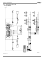
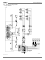
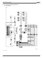
5.4 Electrical wiring diagram ...........................................................................................................................57
5.4.1 Electrical wiring diagram LM .........................................................................................................58
5.4.2 Electrical wiring diagram CLAM ....................................................................................................59
5.4.3 Electrical wiring diagram CLAM + HL ...........................................................................................60
5.5 Authorized service and technical support .................................................................................................61
6
Use of the parts lists .........................................................................................................................................62
4
Version 2011v1
Preface
This manual
This manual contains the basic instructions for repairs and general maintenance of the Puma Kinetic electric
wheelchair.
Mechanics who do repairs on this wheelchair must be well trained and familiar with the repair methods and the
maintenance of the Puma Kinetic electric wheelchair.
It is important to see to it that work is always done safely, particularly with respect to activities where the wheelchair
must be lifted up.
We advise that you contact our service department before doing repair work on a wheelchair that has been
involved in an accident.
The following specifications are important when ordering parts:
-
Model
Manufacture year
Color
Identification number
Part number
Name of the relevant part
This information can be found on the identification plate. See 'Identification of the product'.
EBAPU-020003000-nl.doc
Version 2011v1
5
Preface
Product reference
XXXXXX-010004000-en.doc
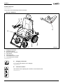
The product has the following decals and labels.
•
See fig. 010004010.
C B
A
E
F
D
G
010004010
•
A.
B.
C.
D.
E.
F.
G.
Charging connection
Controller caution!
Review owner's manual
Free Wheel
Automatic fuse
Tire pressure swivel castor
Tire pressure drive wheel
EBAPUM-010004010-en.doc
A.
Charging connection
For charging the batteries, see 'charging'.
PICPRO-010004210-en.doc
B.
Controller caution!
Use caution when adjusting the controller to avoid obstructions.
PICPRO-010004230-en.doc
6
Version 2011v1
Preface
C.
Review owner's manual
The wheelchair should only be used after the owner's manual has been studied carefully.
Never use the wheelchair before having reviewed and understood the contents of the manual.
PICPRO-010004250-en.doc
D.
Free Wheel
1.
Lever in the lowest position:
The drive of the motors is switched on: The wheelchair can be electrically driven.
Lever in the highest position:
The drive of the motors is disconnected: the wheelchair can be pushed.
2.
PICPRO-010004310-en.doc
E.
Automatic fuse
The wheelchair has a safety fuse feature. See 'automatic fuse' and 'faults'.
PICPRO-010004270-en.doc
MAX.
3,5
BAR
F.
Tire pressure swivel castors
For tire pressure of the swivel castors, see 'product specification sheet'.
PICPRO-010004320-en.doc
MAX.
2 BAR
G.
Tire pressure drive wheels
For tire pressure of the drive wheels, see 'product specification sheet'.
PICPRO-010004330-en.doc
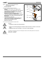
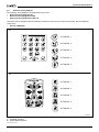
The following pictograms are used in this manual:
XXXXXX-010004020-en.doc
CAUTION
Procedures that can result - if they are not executed properly - in damage to the product, the
environment, or human injury.
PICDOC-010004110-en.doc
ATTENTION!
Suggestions and advice for conducting the relevant tasks or activities more easily.
PICDOC-010004120-en.doc
Consult the specified information source(s) first.
PICDOC-010004130-en.doc
Pull the charge cord out of the charging connection of the electric wheelchair before doing any
maintenance on the wheelchair.
PICDOC-010004140-en.doc
Version 2011v1
7
Preface
Available documentation
The following technical documentation is available for this wheelchair:
- Owner's manual
- Service manual.
XXXXXX-010005000-en.doc
Service and technical support
For information concerning specific settings, maintenance or repair work please contact your dealer. He is always
prepared to help you.
Ensure you have at hand:
Model
Manufacture year
Identification number
This information can be found on the identification plate. See 'Identification of the product'.
XXXXXX-010006000-nl.doc
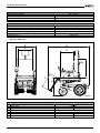
Identification plate
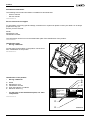
•
See fig. 010007000.
On this plate (A) information on the product can be found.
See: 'Identification of the product'.
EBAPUM-010007000-en.doc
A
010007000
Identification of the product
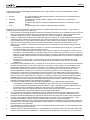
•
See fig. 010007010.
For the place of the identification plate, see 'main
components'.
XXXXXX-010007010-en.doc
LAGE DIJK 10
5705 BZ HELMOND
THE NETHERLANDS
•
Model
Manufacture year
Identification number
User area indoors or outdoors
Maximum load in kg
¤
A.
B.
C.
D.
E.
A
B
C
CAT
2000
IDNR.: CT 00004
USAGE:
INDOOR/OUTDOOR
GEBRUIKSGEBIED: BINNEN/BUITEN
GEBRAUCHSBEBIET: INNERHALB/AUSSERHALB
MAX.LOAD/MAX.BELASTB./ZUL.GESAMTGEW.: 100 KG
TYPE/TYPE/TYP:
YEAR/JAAR/JAHR:
D
E
8
010007010
Version 2011v1
Preface
Warranty stipulations concerning the wheelchair
In the following warranty and liability stipulations the terms and definitions as summed up hereafter must be
explained as follows:
•
Product:
•
Customer:
-
Dealer:
•
User:
The hand-operated or electrical wheelchair or electrical scooter manufactured and
delivered by Handicare.
The person who directly obtains a Product from Handicare or an authorized
representative.
The person who delivers a Product obtained from Handicare to customers or third
parties.
The person who uses a Product manufactured by Handicare.
Irrespective of what is determined concerning warranty conditions applicable to the Product, in any case the
following applies with regard to the warranty:
1.
Except insofar as described otherwise Handicare guarantees the Product for its suitability for the purpose for
which the Product is intended - all of these points as described in this manual - and for the quality of the
material of which the Product is made and the manner in which the Product is manufactured.
2.
Repairs or replacement of parts of the Product that may be necessary as a result of faults that are based on
qualitatively faulty material or manufacturing errors will be executed free of charge, as long as such faults
occurred within one (1) year after the date of delivery of the Product to the Customer. The parts to be
replaced must be shipped post-paid to Handicare. Disassembly or assembly of these parts is for the
expense of the Customer. Therefore the following cases are not eligible for free repair or replacement as
meant above:
− The repair or replacement that is necessary in connection with faults that arise after one (1) year after
the date of delivery of the Product to the Customer;
− The repair or replacement that is required in connection with faults due to improper or careless use of
the Product or that are based on the Product being used for another purpose than the one for which it is
intended, in which regard it applies that if the Customer is a Dealer, this Dealer will indemnify Handicare
against possible claims from Users or other third parties for faults based on an incorrect or careless use
of the Product;
− Parts that are subject to wear, and the need for repair or replacement of the parts are the actual
consequence of normal wear. These can include, but are not limited to, tires, shrouds, arm-pads,
seatings etc.
3.
Irrespective of that stipulated under 2, it applies as far as an electric Product is concerned that with regard to
the battery that forms part of the Product warranty is only given in case of faults or non-functioning of the
battery that are demonstrably the direct consequence of material or manufacturing errors. A fault or nonfunctioning of the battery as a result of normal wear is not covered by the warranty as meant in these
warranty stipulations. Similarly not covered by the warranty are faults or non-functioning that are the
consequence of improper or unprofessional use of the Product or the battery that is part of the Product,
including the incorrect charging of the battery and the failure to carry out timely and good maintenance, in
which context it also applies that if the Customer is a Dealer, this Dealer will indemnify Handicare against
possible claims from Users or other third parties that are based on the above mentioned improper or
unprofessional use of the Product or the battery that is part of the Product. Handicare does not guarantee
batteries provided by dealers or purchased by the customer.
4.
The warranty conditions as mentioned in above stipulations in any case become null and void if:
− The guidelines of Handicare for the maintenance of the Product are not, or insufficiently, followed;
− A necessary repair or replacement of parts is based on neglect, damage or abuse of the Product or a
use of the Product for another purpose than the one for which it was intended;
− Parts of the Product are replaced by parts of another origin than those which Handicare uses and/or
parts of the Product are replaced without the permission of Handicare.
5.
The warranties as mentioned in stipulations 1 through 3 also become null and void if what is involved is
re-used by a new user within the warranty period and that such re-use necessitates adaptations to the
wheelchair and those adaptations are carried out without the instructions and/or at the order of Handicare.
6.
To retain rights under the above delineated warranties the Customer must, in case of damage or other
calamities, as rapidly as possible contact Handicare and inform them as fully as possible.
The possibility of taking recourse to the above-mentioned warranty conditions becomes null and void for the
Customer in any case after 20 workdays after the claim situation or the calamity arises that was the reason
for the recourse to the guarantee.
7.
The replacement of a part or the repair or the reconditioning of the Product within a current warranty period
does not extend the warranty period.
8.
Handicare gives no warranty on repair to or reconditioning of the Product carried out other than under order
of and/or at the instructions of Handicare. If repairs and/or reconditioning are executed by or on behalf of a
Version 2011v1
9
Preface
Customer, the Customer indemnifies Handicare with respect to the claims of third parties who result, in the
broadest sense of the word, from such repairs or reconditioning.
EBAXXX-010008010-en.doc
Liability stipulations concerning the Product
Irrespective of what is determined regarding liability in the general conditions applicable to the Product, with regard
to liability in any case the following applies:
1.
taking into consideration the following stipulations, Handicare only accepts liability for loss due to death or
physical injury that is the result of a defect in the Product for which Handicare is responsible and for damage
to another object that is the private property of the user of the Product, as long as said loss is the direct
result of a fault in the Product.
2.
Handicare accepts no other or further liability than delineated under 1. In particular Handicare accepts no
liability for consequential damage, in any form whatsoever.
XXXXXX-010008020-en.doc
Used wheelchairs and the environment
If your wheelchair has become superfluous or needs to be replaced, it can usually be taken back
by your dealer. If this is not possible, please contact your local authorities for the possibilities of
recycling or an environmentally friendly way of disposing of the used materials.
For the production of the wheelchair several plastics and metals have been used. The wheelchair
also contains electronic components that must go to electronic waste. Used batteries belong to
chemical waste.
EBAXXX-010009000-en.doc
1
Use according to purpose
The electrical wheelchair Puma Kinetic has been designed for the transport of persons to a weight of maximally
120 kg (275 lbs).
Your dealer should give you good user's instructions before you can independently operate the product and
participate in traffic.
You must be able to correct the consequences of actions while driving the Puma Kinetic.
Consider operating the Puma Kinetic under the monitoring of an experienced dealer during first operations.
The Puma Kinetic wheelchair is not a sports wheelchair.
The wheelchair has been designed for use in and outdoors.
The Puma Kinetic has a maximum speed of 10 km/hour.
If you use the wheelchair for other purposes than those for which it is intended, Handicare accepts no liability
whatsoever for damage or injury resulting from such use other than that for which the wheelchair was developed
and designed.
EBAPUM-010010000-en.doc
'Use according to purpose' as established in EN 292-1 is the use for which the technical product is suitable according to the statement of the manufacturer, including his
instructions in the sales brochure. In case of doubt this is the use that follows from the construction, execution and function of the product. Use according to purpose also
includes taking into consideration the instructions in the owner's manual.
10
Version 2011v1
General safety regulations and instructions
1 General safety regulations and instructions
Handicare accepts no liability whatsoever for damage or injury caused by the failure to (strictly) adhere to the safety
guidelines and instructions or else due to carelessness during the use and cleaning of the wheelchair and possible
accessories. Depending on the specific work circumstances or the accessories used, additional safety instructions
may be required. Please contact your dealer immediately if you observe a potential danger during the use of the
product.
The user of the wheelchair (see under 'use according to purpose') is at all times fully responsible
for the fulfilment of the locally applicable safety regulations and guidelines.
1.1
Decals and instructions on the wheelchair
Signs, symbols and instructions placed on this wheelchair comprise part of its safety facilities. They must never be
covered or removed and must remain present and clearly legible throughout the entire lifespan of the wheelchair.
•
Immediately replace or repair illegible or damaged signs, symbols and instructions.
•
Contact your dealer with regard to this.
•
1.2
Technical specifications
The technical specifications may not be changed.
1.3
Modifications
Modification of (parts of) this product is not permitted.
1.4
Safety
To avoid accidents and undesirable situations, it is of great importance to pay attention to the following safety
instructions.
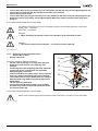
-
• Pay extra attention to riding on slopes:
Never drive with the Puma Kinetic on a slope with an angle of more than 11°
(ascending percentage of 20%).
On slopes always drive slowly and with awareness.
The wheelchair is less stable on a slope and has less sideways stability.
• Never take curves at full speed. Decrease speed on the approach and on the curve.
• Be sure that no items of clothing hang loose. These could become caught between the
wheels.
-
• Adjust your riding according to the circumstances:
Drive carefully on slippery roads, resulting from rain, ice, or snow!
Prevent the Puma Kinetic from coming into contact with rain and seawater. Sea water is caustic and
may damage the wheelchair.
Prevent the Puma Kinetic from coming into contact with sand. Sand can affect the moving parts of the
wheelchair, resulting in unnecessarily rapid wear.
• Never operate the wheelchair when you are under the influence of drugs, alcohol or
medication that could affect your driving ability.
• You must have sufficient visual acuity to be able to drive safely in the wheelchair.
• You are obliged to put the lights on when the view is hindered.
• The magnetic key with which the wheel chair is switched on and off can have an
influence on the magnetic strips of credit cards.
Do not store the magnetic key with credit cards and similar cards.
• Avoid the joystick inadvertently contacting other surfaces to prevent unintentional
movement.
Version 2011v1
11
General safety regulations and instructions
• The standard version of your wheelchair was tested according to the strictest EMC
requirements. Mobile telephones have no influence on the driving behavior of the
wheelchair.
When using a mobile telephone in the vicinity of a wheelchair with special adaptations,
you are advised to first switch off the wheelchair.
• Your wheelchair may influence electromagnetic fields such as alarm systems.
EBAPUM-010100000-en.doc
12
Version 2011v1
Adjustment options
2 Adjustment options
XXXXXX-010500000-en.doc
®
2.1
The Sedeo seating frame
The wheelchair has a unique seating system made by Handicare, known as Sedeo®.
Sedeo is the Latin word for: 'I sit'.
Functions of the Sedeo® seating system
The Sedeo® seating system offers outstanding support for:
1. The body:
The sitting position is well supported with a total range of solutions for the head, the torso, arms, pelvis, upper
legs, lower legs and feet, both in terms of posture and pressure distribution.
2. The range of body functions:
The body is supported in such a way that you can carry out a wide variety of actions, because you can move
into a stable sitting position.
A specialist or authorized representative should adjust the wheelchair. Erroneous settings can lead to negative
consequences for both your sitting position and the driving characteristics, as well as performance of your
wheelchair.
EBAXXX-010501000.en.doc
®
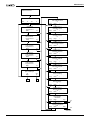
2.1.1 Adjusting the Sedeo seating frame
•
See fig. 010501010.
All body parts are supported by the proper setting of the
Sedeo® seating system.
This includes:
A. Seat.
B. Backrest.
C. Side panel.
D. Armrest.
E. Legrest
F. Headrest (option).
G. Controller
F
B
G
D
A
C
E
010501010
EBAPUM-010501010.nl.doc
Version 2011v1
13
Adjustment options
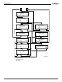
2.2
•
Seating adjustments
See fig. 010502000.
E
B
F
A
C
D
010502000
The following parts of the seating system can be adjusted:
•
The height (A). See 'Adjusting the seat height'.
•
The depth. See ‘Adjusting the seat depth' (B) and 'Position of the seat cushion' (C).
•
The width (D). See 'Adjusting the seat width'.
•
The back angle (E). See 'Adjusting the back-support angle'.
•
The seat angle (F). See 'Adjusting the seat angle'.
EBAPUM-010502000.nl.doc
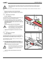
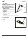
2.2.1 Adjusting the seat height
•
See fig. 010502010.
A good seat height setting is important to be able to easily take a
seat at tables and desks. A minimum seat height is also important
in order to keep the footplates free from ground obstructions
(thresholds, curbs etc).
The seat height will generally be an average level between these
two.
B
The seat height of the Puma Kinetic wheelchair can be adjusted
to five levels.
The chair is installed on an interface, which is equipped with
tubing. This interface can be adjusted on the carrier to 5 different
heights, in 25 mm steps. Depending on the desired seat height
the interface can be adjusted one or more holes: upward or
downward.
A
010502010
For the seat height adjustment you should leave the
wheelchair. The adjustment must be done as follows:
•
Loosen the Allen bolts (A) on both sides of the carrier with an Allen key with a key width of 8 mm and
remove them.
14
Version 2011v1
Adjustment options
When removing the second Allen bolt the chair can slide downward and your fingers may get
caught between the carrier and the interface. Hold the chair so that it cannot slide during this
procedure.
A bush can be slid over each bolt. Should a bush come out when taking out a bolt, slide the bush back onto the
bolt.
•
•
Bring the chair (B) up to the desired height.
Replace the Allen bolts and tighten them securely.
EBAPUM-010502010.nl.doc
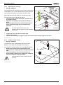
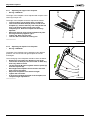
2.2.2 Adjusting the seat depth
•
See fig. 010502020.
The seat depth can be adjusted between approximately 44 cm
and 52 cm (17' and 20') by shifting the backrest.
The seat depth adjustment should be done as follows:
•
Loosen the locking bolts (A) on both sides of the
chair frame a half turn (180°) loose with an Allen key
with a key width of
4 mm.
•
Slide the backrest (B) to the desired depth.
To promote good circulation in your legs and
not restrict the nerves, we recommend at
least 2 cm (approx. 1") free space between
your knees and the front of the seat.
•
A
Tighten the locking bolts on both sides securely.
B
010502020
XXXXXX-010502020.en.doc
2.2.3 Adjusting the seat width
•
See fig. 010502030.
A
The space between the two armrests can be adjusted as
desired between 36 cm and 52 cm (15" and 20"). The holder
for the armrests can be shifted in width on both sides
Do the adjustment, or have it done by someone, and then
take your seat in the chair.
The seat width adjustment should be done as follows:
•
Loosen the two Allen bolts (A) on both sides of the
chair frame with an Allen key with a key width of 4
mm.
•
Slide the armrests to the desired width.
Set the side panels equally, in such a way
that you feel comfortable and that you have
enough support and enough freedom of
movement.
•
010502030
Tighten the Allen bolts properly on both sides.
XXXXXX-010502030.en.doc
Version 2011v1
15
Adjustment options
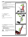
2.2.4 Adjusting the seat angle
•
See fig. 010502040.
The seat part of your wheelchair can be set at an angle that is
comfortable for you. In this adjustment the angle of the entire
chair is tilted with respect to the bottom part of the chair.
Before adjusting the seat angle you must leave the chair.
The seat angle must be adjusted as follows:
•
Loosen nuts (A) on both sides with a spanner with a
key width of 13 mm.
•
Adjust the new angle by turning the nuts (B) up or
down.
See to it that the nuts (A) are turned sufficiently far
down so that the height can be set without any
problems.
For each degree that the seat is set
backward the seat height rises approximately
5 mm (1/4").
•
•
•
B
A
010502040
Tighten the nuts in the position finger-tight.
Try the new position.
Lock the new seat angle by tightening the nuts on both sides securely against each other.
EBAPUM-010502040-en.doc
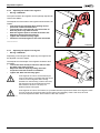
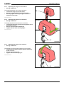
2.2.5 Position of seat cushion
•
See fig. 010502050.
The seat cushion can be fastened to the frame in three
positions. This allows the seat depth to be reduced.
The location of the seat cushion can be changed as follows:
•
Remove the seat from the chair by pulling it up.
•
Loosen the two clamps (B) with a Phillips screwdriver
PH2.
•
Place the clamps at one of the other places (A).
•
Place the seat on the chair by clicking the clamps on
the front round tube of the seat frame.
Check whether the seat is clicked in place
securely.
XXXXXX-010502050.en.doc
16
A
B
010502050
Version 2011v1
Adjustment options
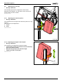
2.3
•
Adjusting the back-support angle
See fig. 010503010.
B
For optimal seating comfort the angle (B) of the backrest can
be adjusted continuously.
The angle of the backrest can be adjusted as follows:
•
Loosen the two Allen bolts (A) on the left side of the
back, under the seat, two turns with an Allen key with
a key width of 4 mm.
•
Adjust the desired back angle (B).
•
Tighten the Allen bolts again.
A
EBAPUM-010503010.nl.doc
010503010
2.4
•
Adjusting the legrests
See fig. 010504000.
C
Adjustment possibilities of the legrests:
A. Length.
B. Width.
C. Depth.
B
Legrests also have an optional angle adjustment.
XXXXXXX-010504000.en.doc
A
010504000
2.4.1 Adjusting the length of the lower-legrests
•
See fig. 010504010.
The adjustment of the length (L) of the legrests should be
done as follows:
•
Loosen the set bolt (A) a few turns with an Allen key
with a key width of 4 mm.
•
Adjust the length of the legrest.
•
Tighten the set bolt again.
L
A
Make sure that there is sufficient free space
under both footplates to be able to drive the
wheelchair over obstacles, without impacting
the footplates.
XXXXXX-010504010.en.doc
010504010
Version 2011v1
17
Adjustment options
2.4.2 Adjusting the width of the legrests
•
See fig. 010504020.
The space between two legrests can be optimally adjusted for
various seat widths.
The adjustment of the width of the legrests should be done as
follows:
•
First remove the calf strap (A) by pulling out the
piece that is attached with velcro.
•
Loosen the two setscrews (B) a few turns with an
Allen key with a key width of 4 mm.
•
Slide the legrests apart or toward each other and
determine the desired seat width (L).
•
Tighten the set bolts securely again.
•
Fasten the calf strap again for this new seat width.
XXXXXX-010504020.en.doc
1
B
L
2
A
010504020
2.4.3 Adjusting the depth of the legrest
•
See fig. 010504030.
Depending on the length of the upper legs, the legrests can
be adjusted in terms of depth.
The adjustment of the depth of the legrests should be done
as follows:
•
Loosen the Allen bolt (A) a few turns with an Allen
key with a key width of 6 mm.
•
Adjust the desired depth by sliding the entire
suspension bracket forward or backward.
•
Tighten the Allen bolt securely again.
If the legrests are set too far backward (too
close to the chair) it is possible that the swivel
castors touch the legrests when driving
backward or maneuvering. If this is the case,
the legrests must be brought forward a bit:
there must be at least 1 cm (3/8") cm
between wheel and legrest.
A
010504030
If the legrests are set too far forward, it is possible that the suspension bracket of the legrest comes
out from under the seat and pushes into the knees uncomfortably. If this is the case, the seat
should be adjusted forward. See 'Position of the seat cushion'.
EBAXXX-010504030.en.doc
18
Version 2011v1
Adjustment options
2.4.4 Comfort legrest with gas-spring angle adjustment
•
See fig. 010504050.
The comfort legrests are angle adjustable (A) independently
of each other. There is a gas spring on each legrest that
delivers enough force to allow the legrest to go up easily.
If you wish to adjust the angle of the legrest, move your leg
upward so that the legrest can move upward freely.
B
The adjustment of the angle of the legrests can be done as
follows:
•
Push the handle (B) forward.
Now the gas spring is unlocked.
•
Place your leg in the desired position and hold it until
the legrest comes against your leg.
•
Release the handle.
In this position the legrest is fixed and you can allow
your leg to rest.
A
010504050
If the leg support is too high, do the following:
•
Push the handle (B) forward.
Now the gas spring is unlocked.
•
Push the legrest with a light pressure from your leg in the desired position and hold it in that position.
•
Release the handle.
In this position the legrest is fixed and you can allow your leg to rest.
XXXXXX-010504050.en.doc
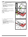
2.5
•
Adjusting the footplate
See fig. 010506000.
The following can be adjusted on the footplate:
A. The angle.
B. The depth.
B
The footplate can also be folded up to ease transfer and
positioning.
XXXXXX-010506000.en.doc
A
010506000
Version 2011v1
19
Adjustment options
2.5.1 Adjusting the angle of the footplate
•
See fig. 010506010.
B
The angle of the footplate can be adjusted with respect to the
lower leg in steps of 5°.
The angle of the footplate should be adjusted as follows:
•
Loosen locking nut (A) with a large screwdriver.
•
Then loosen the Allen bolt (B) on the inside of the
footplate (C), with an Allen key with a key width of 6
mm, so far that the teeth of the hinge come
completely free. Now the footplate can be freely
adjusted.
•
Adjust the desired angle of the footplate and push
the hinge manually together again.
•
Tighten the Allen bolt securely.
•
Lock the Allen bolt with the locking nut.
C
A
XXXXXX-010506010.en.doc
010506010
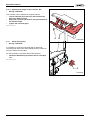
2.5.2 Adjusting the depth of the footplate
•
See fig. 010506020.
The depth of the footplate can be adjusted in two different
positions. For this the left and right footplate should be
exchanged.
The exchanging of the footplates should be done as follows.
•
Remove the calf strap. See 'Removing calf strap'.
•
Loosen the set bolt (A) a few turns with an Allen key
with a key width of 4 mm.
•
Let the footrest (B) lower together with the profile (C)
from the top tube (D).
•
Exchange both footplates for each other and slide
them into the top tubes.
•
Adjust the footplates to the desired height.
•
Tighten the setscrews.
•
If necessary readjust the angle of the footplate, see
'footplate angle adjustment'.
D
A
C
B
010506020
XXXXXX-010506020.en.doc
20
Version 2011v1
Adjustment options
2.6
•
Adjusting the armrest
See fig. 010508000.
The armrests provide support to the arms to limit the burden
on the shoulders. For this purpose the armrests can be
adjusted in terms of height (A) and depth (B).
The armrests can also be removed (C), to make space to
leave the wheelchair sideways, for example if you make a
transfer from a car seat.
By removing the armrests the wheelchair can be made
smaller, which and it simplifies transport.
C
EBAPUM-010508000.nl.doc
2.6.1 Adjusting the height of the armrest
•
See fig. 010508010.
The height adjustment can be done as follows:
•
Loosen set bolt (A) with an Allen key with a key width
of
4 mm.
•
Slide the armrest (B) to the desired height.
A
B
B
010508000
Make sure that the arms are well supported,
without the shoulders being pushed upward.
•
Tighten the setscrew again.
A
EBAPUM-010508010.nl.doc
010508010
2.6.2 Adjusting the depth of the armrest
•
See fig. 010508020.
To adjust the depth of the armrest, the chair should be raised
in order to be able to reach the depth-adjustment screws.
The chair should be raised as follows (you have to leave the
chair first):
Using a 13 mm spanner, loosen the nuts (A) a number of
turns in order to raise the chair sufficiently to be able to
loosen the Allen bolts (B).
Now, you can adjust the depth of the armrests.
Make sure the chair is supported by a
wooden block or something similarly strong,
so that the chair cannot come down and
risking someone’s fingers from getting
jammed underneath.
A B C
010508020
The depth adjustment of the armrests should be done as follows:
•
Loosen the Allen bolts (B) on both sides of the chair with an Allen key with a key width of 4 mm.
•
Slide the armrests (C) in the desired position.
•
Tighten the Allen bolts again.
Note that the adjustment is carried out equally on the left and the right side.
Version 2011v1
21
Adjustment options
•
•
Take away the supports from under the chair and lower the chair to the ground.
Securely tighten both nuts again.
EBAPUM-010508020.nl.doc
2.7
•
Adjusting the height of the side panel
See fig. 010509010.
The side panels should provide sufficient support and
sufficient freedom of movement so that you can assume a
comfortable position in the chair.
The side panels can be adjusted in height.
•
•
•
•
•
•
The height adjustment can be done as follows:
Flip off the studs from the inside of the side panel.
Loosen both crosshead screws (A) a couple of twists,
using a Phillips screwdriver PH 2. Keep the nuts from
turning by holding them on the inside with a socket
wrench with a key width of 8 mm.
Slide the side panel (B) at the desired height.
Tighten the crosshead screws securely again.
Replace the studs.
B
A
010509010
EBAPUM-010509010.nl.doc
2.8
•
Adjusting the headrest (option)
See fig. 010510000.
A headrest can be attached to the back of the backrest.
The headrest can be adjusted in:
A. Height.
B. Depth.
C. Angle.
C
A
XXXXXX-010510000.en.doc
B
010510000
22
Version 2011v1
Adjustment options
2.8.1 Adjusting the height of the headrest
•
See fig. 010510010.
The height adjustment can be done as follows:
•
Loosen the wing nut (A) a few turns.
•
Slide the headrest (B) to the desired height.
•
Securely tighten the wing nut again so that the
headrest cannot shift.
B
XXXXXX-010510010.en.doc
2.8.2 Adjusting the depth of the headrest
•
See fig. 010510020.
A
The depth adjustment should be done as follows:
•
Loosen the two bolts (A) a bit with a spanner with a
key width of 10 mm.
•
Set the desired headrest depth (B).
•
Tighten the two bolts securely again.
010510010
XXXXXX-010510020.en.doc
B
A
010510020
2.8.3 Adjusting the angle of the headrest
•
See fig. 010510030.
B
The adjustment of the angle should be done as follows:
•
Loosen the bolt (A) a bit with a spanner with a key
width of 10 mm.
•
Set the desired angle (B).
•
Tighten the bolt securely again.
XXXXXX-010510030.en.doc
A
Version 2011v1
010510030
23
Adjustment options
2.9
•
Adjusting the calf strap
See fig. 010511000.
A
The calf strap (A) serves to support the calves and is
attached to the legrests. The calf strap can be removed to
make transfer in and out easier.
EBAPUM-010511000.nl.doc
2.10
Adjusting the calf pad (option)
•
See fig. 010512000.
A
The calf pad serves to support the calf and is placed on a leg
support.
The calf pad can be adjusted in:
A. Height.
B. Angle.
XXXXXX-010512000.en.doc
010511000
B
010512000
2.10.1 Adjusting the height of the calf pad
•
See fig. 010512010.
The calf pad can be adjusted in height as follows:
•
Loosen Allen screw (A) a few turns with an Allen key
with a key width of 4 mm.
•
Slide the calf pad up to the desired height.
•
Tighten the Allen screw again.
XXXXXX-010512010.en.doc
A
010512010
24
Version 2011v1
Adjustment options
2.10.2 Adjusting the angle of the calf pad
•
See fig. 010512020.
A
The angle of the calf pad can be adjusted as follows:
•
Loosen nut (A) a few turns with a spanner with a key
width of 13 mm.
•
Place the calf pad (B) in the desired position.
•
Tighten the nut again.
XXXXXX-010512020.en.doc
2.11
Adjusting the position of the controller 'DX'
•
See fig. 010513000.
The controller comprises all the components needed to
operate the wheelchair.
On behalf of the comfort of the driver the controller can be
adjusted in the following aspects:
A. Depth.
B. Height.
B
010512020
EBAXXX-010513000.en.doc
A
010513000
2.12
Adjusting the depth of the controller 'DX'
•
See fig. 010513010.
The controller can be adjusted in depth as follows:
•
Loosen setscrew (A) a few turns with an Allen key
with a key width of 4 mm.
•
Slide the controller (B) at the desired place (forward
or backward).
•
Tighten the setscrew again.
EBAXXX-010513010.en.doc
A
B
010513010
Version 2011v1
25
Adjustment options
2.12.1 Adjusting the height of the controller 'DX'
•
See fig. 010513020.
The controller can be adjusted in height as follows:
•
Loosen setscrew (A) a few turns with an Allen key
with a key width of 3 mm.
•
Adjust the controller (B) with its swing mechanism to
the desired height.
•
Tighten the setscrew again.
EBAXXX-010513020.en.doc
A
B
010513020
2.13
Safety belt (option)
•
See fig. 010515000
It is possible to equip the wheelchair with a safety belt.
The safety belt gives extra sitting stability during normal use.
Ask your dealer for information.
For the assembly of the safety belt do the following:
•
Fasten the belt buckle (A) with the aid of a bolt plus
nut.
EBAPUM-010515000.nl.doc
A
010515000
26
Version 2011v1
Maintenance
3 Maintenance
XXXXXX-01010700000-nl.doc
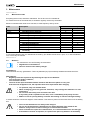
3.1
Maintenance table
Everything that is used, should be maintained. This is also true for a wheelchair.
For trouble-free use of the wheelchair, it should be regularly serviced by the dealer.
Below is indicated what needs to be checked, in what frequency and by whom.
Time
Description
Daily
Weekly
Monthly
•
Annually
•
•
•
•
•
•
•
•
•
•
•
Charging of the batteries after each use
Checking the tire pressure
Cleaning of the wheelchair
Cleaning of the upholstery (if necessary)
Checking the electrical system
Checking the batteries
Checking the drive
Checking the mechanical parts
Checking the bearings
Checking the suspension
Checking the tires
Checking all fastenings and bolts; tighten if
necessary
To be executed by
User
Dealer
X
X
X
X
X
X
X
X
X
X
X
X
It is recommended to have your wheelchair serviced by your dealer at least once a year, or, in case of intensive
use, once every six months.
EBAXXX-010700010-en.doc
3.2
Batteries
For maintenance see the following documentation:
• Regulations on the batteries.
• Owner's manual of the battery charger.
Dry batteries:
The wheelchair has 'dry' gel batteries. These dry batteries (dry-fit) are entirely sealed and maintenance free.
Wet batteries:
•
Regularly check the liquid level by removing the caps on the batteries:
once every two weeks in summer;
once a month in winter.
•
The level of the liquid should be between 5 and 10 mm above the plates in every cell.
If the level has dropped too far, the liquid will have to be replenished after charging.
• To replenish, only use distilled water.
• When recharging, gases are given off. Therefore, only recharge the batteries in a wellaired space.
• Do not touch the battery acid: it will burn the skin.
If any battery acid is spilled onto the skin, rinse it immediately with plenty of water.
• Make sure not to spill any battery acid onto the clothing: it will burn through clothing..
A sticker shows the connection diagram of the batteries. This sticker is placed on the inside of the lid of the battery
box.
• See to it that the batteries are always well charged.
• Do not use the wheelchair if the batteries are almost depleted. This is bad for the
batteries and you have a risk of coming to an unintended standstill.
• Since wet batteries require more maintenance, it is recommended not to use this type.
• If the batteries need to be replaced, it is preferred to place dry batteries in the battery
Version 2011v1
27
Maintenance
box..
EBAPUM-010701000.nl.doc
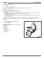
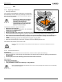
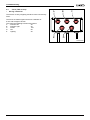
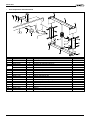
3.2.1 Replacing the batteries
•
See fig. 010701010.
If the capacity of the batteries is reduced to the extend that
the wheelchair can only make very short trips, or even none
at all, the batteries are at the end of their lifespan. Replace
them as soon as possible.
A
B
F
I
D
E
• Contact your dealer who can advise
you what type of batteries are best
suitable for the wheelchair.
• Avoid damage to the batteries when
replacing them: this may cause the
batteries to start leaking.
G
H
The batteries should be replaced as follows:
C
•
Switch off the wheelchair.
•
Switch off the automatic safety fuse. See 'Automatic
safety fuse' and ‘Malfunctions’.
010701010
•
Loosen the caps (A).
•
Raise the lid (B) a little at the back, and carefully slide it off the battery box.
•
Loosen the bolt from the negative (-) pole (C) and remove the battery clamp from the battery pole.
•
Now loosen the bolt from the positive (+) pole (D) and remove the battery clamp from the battery pole.
•
Then loosen the bolts from the battery clamps (E and F) from the power cable (G) and remove the
cable.
•
Lift the back battery (H) from the battery box using the carrying belts.
•
Slide the front battery (I) to the back, and take it out of the battery box as well.
New batteries are placed in the reverse order.
As soon as the new batteries are placed and the battery box is closed, the batteries must be
charged.
EBAPUM-010701010.nl.doc
3.2.2
Cleaning the batteries
Dry batteries:
These are in principle maintenance free. Nonetheless, attention must be paid to the following:
•
Keep the batteries clean and dry: dirt and water can cause a leak, so that the capacity of the batteries
will decrease.
•
Cleaning the poles: after cleaning, grease them with acid-free Vaseline.
•
Wet batteries:
These require maintenance:
•
See ‘Battery maintenance’.
•
They should be cleaned in the same way as dry batteries.
Never completely deplete the batteries! This can seriously damage the batteries and considerably
decrease their lifespan.
EBAPUM-010701020.nl.doc
28
Version 2011v1
Maintenance
3.3
Wheels
For the proper functioning of the wheelchair it is very important that the tires are kept at the correct pressure.
Soft tires yield less optimal driving for the wheelchair. It also costs more energy to move the wheelchair, putting a
heavier load on the batteries. Moreover, tire wear when driving on soft tires is unnecessarily great.
For the right tire tension, see 'Product specifications'.
Note when filling the tires that the pressure never exceeds the maximum specified value provided
in the table 'product specification', or as indicated on the side of the tire. In case of doubt contact
the dealer / supplier.
For inspection of the tires, see 'maintenance table'.
EBAXXX-010705000-en.doc
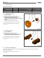
3.3.1
Tire repair drive wheels
When repairing the inner tube of a drive wheel, the neutral should be switched off, so that the wheel does not turn
along.
Repairing a leaking tire should be done as follows:
•
Support the wheelchair so that the wheel is elevated.
•
Let the tire run empty completely by pulling out the valve.
•
Using tire levers, pull the front of the tire across the edge of the rim.
•
Carefully pull the inner tube across the edge of the rim.
•
Push the valve from the opening in the rim.
•
Pull the inner tube from the tire for repair or replacement.
•
Repair the inner tube or replace it.
Now, the repaired or new inner tube should be placed as follows:
•
Put the valve of the inner tube through the opening in the rim.
•
Press the inner tube into the tire.
•
Place the tire around the rim.
•
Use tire levers to place the tire around the rim: be careful not to damage the inner tube with the tire
levers.
The inner tube must not become jammed between the rim and the tire.
•
•
Pump up the inner tube, see 'technical data'.
Remove the support from the wheelchair.
The wheelchair is ready to drive again.
EBAPUM-010702010-nl.doc
Version 2011v1
29
Maintenance
3.3.2
Replacing the tire of the drive wheel
When replacing a tire of a drive wheel neutral should not be switched off, so that the wheel does not turn along.
The tire should be replaced as follows:
•
Support the wheelchair so that the wheel is elevated.
•
Let the tire run empty completely by pulling out the valve.
•
Using tire levers, pull the front of the tire across the edge of the rim.
•
Carefully pull the inner tube across the edge of the rim.
•
Push the valve from the opening in the rim.
•
Pull the inner tube from the tire.
•
The whole tire can now be removed.
Now the tires (with repaired or new inner tube) should be assembled as follows:
•
•
•
•
Place one side of the tire around the rim.
Put the valve of the inner tube through the opening in the rim and press the inner tube into the tire.
Place the tire around the rim.
Use tire levers to place the tire around the rim: be careful not to damage the inner tube with the tire
levers.
The inner tube must not become jammed between the rim and the tire.
•
•
Pump up the inner tube, see 'technical data'.
Remove the support from the wheelchair.
The wheelchair is ready to drive again.
EBAPUM-010702020-nl.doc
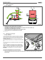
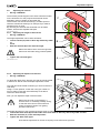
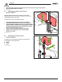
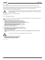
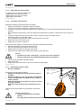
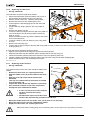
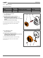
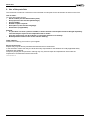
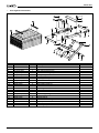
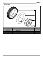
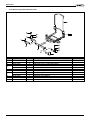
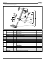
3.3.3 Replacing the drive wheel
•
See fig. 020702040.
When the rim of a drive wheel is replaced, the neutral should not
be switched off, so that the wheel does not turn along.
Replace this as follows:
•
Support the wheelchair so that the wheel is elevated.
•
Remove the cap (A) with a screwdriver.
•
Bend back the lip on the locking plate (B).
•
Using a box spanner with a key width of 17 mm,
remove bolt (C) with the washers that holds the rim
onto the drive unit.
•
Pull the wheel (E) off the shaft.
G
• When the wheel is removed, a key (F)
may come loose or remain in the rim.
This key must be slid into the key way
of the outgoing shaft of the drive unit.
• If there is no key, this will cause drive
F
problems.
• Behind the key, a bush is slid onto the
outgoing shaft. This bush does not have to be removed.
E B C A
D
020702040
Now the new wheel can be assembled as follows:
Put a layer of grease on the outgoing shaft (G) of the drive unit.
Slide the wheel onto the outgoing shaft of the drive unit.
•
•
Attention:
• Make sure that the notch in the rim falls over the key.
• The locking plate has to be replaced: do not use the old one again.
•
•
•
30
Screw the bolt with the rings and the locking plate in the thread hole of the outgoing shaft of the drive
unit and tighten the bolt with the box spanner.
Bend back the lip on the locking plate, so that the bolt is prevented from being unscrewed.
Remove the support from the wheelchair.
The wheelchair is ready to drive again.
Version 2011v1
Maintenance
EBAPUM-020702040-nl.doc
3.3.4 Replacing rim of drive wheel
To replace the rim of the drive wheel, see:
‘repairing the tire of the drive wheel’;
‘replacing the tire of the drive wheel’;
‘replacing the drive wheel’.
EBAPUM-020702030-nl.doc
3.3.5
Tire repair swivel castors
Repairing a leaking tire should be done as follows:
• Support the wheelchair so that the wheel is elevated.
• Let the tire run empty completely by pulling out the valve.
• Loosen the locking nut using a box spanner with a key width of 13 mm and stop the bolt with the same box
spanner.
Now the wheel can be slid out of the fork. Watch the washers that come free: collect them so they will not be
lost.
• Loosen the Allen bolts from the rim halves using an Allen key with a key width of 5 mm.
Now the rim halves can be taken apart.
This released both tires and the valve can be slid out of the rim half.
• Remove the inner tube from the tire.
• Repair the inner tube or replace it.
Now the tire (with repaired or new inner tube) should be assembled as follows:
• Place the (repaired or new) inner tube in the tire.
• Put the valve through the opening in the rim half.
• Slide the other rim half over the hub of the wheel.
• Screw both rim halves with the bolts and locking nuts to each other.
Attention:
• Locknuts may not be used again – use new ones when replacing.
• The inner tube must not be jammed between the two rim halves.
•
•
•
Tighten the locking nuts and hold the bolts.
Pump up the tire.
Replace the wheel in the fork, in the reverse order of disassembly.
EBAXXX-010703010-en.doc
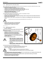
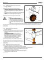
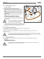
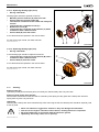
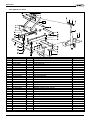
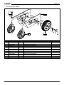
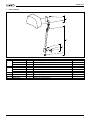
3.3.6 Replacing the swivel castor
•
See fig. 020703030.
Replace the swivel castor as follows:
•
Support the wheelchair so that the swivel castor is
elevated.
•
Remove the plastic cover cap (A) with a screwdriver.
•
Loosen nut (B) using a box spanner with a spanner
width of 19 mm.
•
Now the complete swivel castor (C) can be removed
from the ball head.
Watch the rings under the nut so that they are not
lost.
A
B
C
Now the (new) swivel castor can be placed in the reverse
order.
Adjusting the ball head:
• Tighten nut (B) until the fork starts
moving.
This way, the front wheel is prevented from vibrating.
020703030
EBAPUM-020703030-nl.doc
Version 2011v1
31
Maintenance
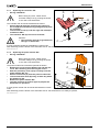
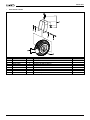
3.3.7 Replacing the wheel of the swivel castor
•
See fig. 020703040.
Replace the wheel of the swivel castor as follows:
•
Support the wheelchair so that the wheel is elevated.
•
Loosen the shaft (A) and the locking nut (B) with
two open-end spanners with a spanner width of 13
mm.
•
Hold onto the wheel (C) and remove the shaft with the
rings.
•
The wheel can now be removed from the fork.
A
B
Now the new wheel can be placed in reverse order.
Attention:
C
• The locknut may not be used again –
use a new one when replacing.
• The locking nut must just be screwed
on: the screw thread of the shaft must
020703040
be clearly visible through the locking
ring.
If the wheel is not placed properly this can lead to very dangerous situations for the user.
After the assembly of the wheel the support can be removed from the wheelchair: the wheelchair is now ready to
operate again.
EBAPUM-020703040-nl.doc
3.3.8 Replacing bearings of ball head
•
See fig. 020703050.
The bearings of the ball head should be replaced as follows:
•
Support the wheelchair so that the swivel castor is
elevated.
•
Disassemble the complete swivel castor, see
'replacing swivel castor'.
•
Disassemble the bearings (A) from the bush (B).
Make sure that the spacing bush (C), which is
mounted in-between the bearings, is not lost.
•
Check the bearings for wear or damage.
A
B
C
Now the (new) bearings can be placed in reverse order.
After the assembly of the swivel castor the support can be
removed from the wheelchair: the wheelchair is now ready to
operate again.
A
EBAPUM-020703050-nl.doc
020703050
3.3.9 Replacing the fork of the swivel castor
The fork of the swivel castor must be replaced as follows:
•
Support the wheelchair so that the swivel castor is elevated.
•
Remove the wheel from the fork; see 'replacing the wheel of the swivel castor'.
•
Remove the fork from the ball head, see 'replacing swivel castor'.
The (new) fork can be placed in reverse order.
•
After placing the complete swivel castor remove the support.
The wheelchair is ready to operate.
EBAXXX-020703060-en.doc
32
Version 2011v1
Maintenance
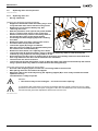
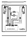
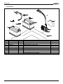
3.4
•
Replacing the spring
See fig. 020705020.
The spring should be replaced as follows:
•
Support the wheelchair under the battery tray in such
a way that both drive wheels remain on the ground.
If the height of the seat can be adjusted electrically, it
should be put into its topmost position.
•
Remove the cover from the battery tray and the rear
cover. See ‘mounting and removing the covers’.
•
Slide the CLAM module (A) up and off the holder.
•
Loosen bolts (B) using an Allen key with a key width
of
4 mm and remove the power module (C).
•
Loosen the bolts (D) using an Allen key with a key
width of 5 mm and stop the locknuts (E) using a
spanner with a key width of 13 mm.
•
Remove the rod (F), together with the spring (G) that
is to be replaced.
A
C B
H
F G
E
D
020705020
Attention!
• The spring is under tension and could suddenly fly off.
• The locknuts may not be used again – use new ones when replacing.
The spring can now be replaced as follows:
•
Mount the rod left or right and push the bolt through the holes.
•
Place locknut and tighten it finger tight.
•
Mount the spring in place.
•
Mount the clamp (H) over the upper and lower rods.
•
Tighten the clamp to such an extent that a second can be mounted to fix the lower rod (F).
•
Tighten both bolts (D).
•
Remove the clamp (H).
•
Mount the power module.
•
Mount the CLAM module.
•
Mount the covers.
•
Remove the support.
The wheelchair is ready to operate.
EBAPUM-020705020-nl.doc
3.5
•
Removing the covers
See fig. 020706010.
The covers should be removed as follows:
•
Loosen the caps (A).
•
Raise the lid (B) a little at the back, and carefully slide
it off the battery box.
•
Lift off the back cover (C), which comes loose when
the caps are unscrewed. Remove the connector for
the lighting.
•
Loosen the Allen bolts (D) with the washers from the
protective cover, using an Allen key with a key width
of
4 mm.
If necessary, take out the automatic fuse as well,
from the right-hand side cover, by unscrewing nut
(E).
•
Remove the protective covers (F).
The covers should be assembled in reverse order.
A
B
C
E
F
D
F
D
020706010
EBAPUM-020706010-nl.doc
Version 2011v1
33
Maintenance
3.6
Replacing drive and components
XXXXXX-020707000-nl.doc
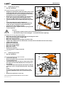
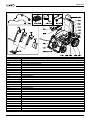
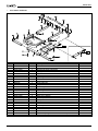
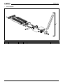
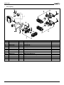
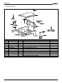
3.6.1 Replacing drive unit
•
See fig. 020707020.
K
L
I
C A
B
The drive unit should be replaced as follows:
•
Support the wheelchair under the battery tray in such
a way that both drive wheels remain on the ground.
G J
•
Remove the cover from the battery tray. See
‘removing the covers’.
•
Slide the protective cover (A) from the power module
(B) up, in order to gain access to the connectors.
•
Pull the connector (C), from the connecting cable of
the relevant drive unit, off the power module.
•
Cut through all cable-wrapping tape that is holding
this cable.
•
Remove the side cover. See 'removing the covers'.
•
Cut off the little tun (D) from the cable.
•
Loosen the nipple (E) using a screwdriver.
H
After this, the inner cable (F) can be pulled away from
the neutral of the vacuum brake (G).
D E F
M
020707020
•
Remove the drive wheel; see 'replacing drive wheel'.
•
Loosen the bolts (H) with the washers, using an Allen key with a key width of 6 mm and stop the
locknuts (I) using a spanner with a key width of 13 mm.
•
Hold securely to the drive unit (J) (support this if necessary) and carefully remove the three bolts with
their rings with which the drive unit is attached to the side frame.
•
The drive unit can now be removed.
•
Loosen the bolt (K) with the washers, using an Allen key with a key width of 6 mm and stop the locknut
using a spanner with a key width of 13 mm. Remove the sliding block (L).
The (new) drive unit can be placed in reverse order.
Use new cable-wrapping tapes to fasten the connecting cable to the drive unit.
After placing the drive unit remove the support.
Adjust the cable of the neutral by turning the adjusting nipples (M) in such a way to make the neutral
operated correctly.
The wheelchair is ready to operate.
•
•
•
Attention:
• The locknuts may not be used again – use new ones when replacing.
In connection with agreements concerning guarantees with the supplier of the drive unit, it is NOT
permitted to take the drive unit apart: every part of the drive unit delivered loose will be immediately
returned and the guarantee stipulations will become null and void.
EBAPUM-020707020-nl.doc
34
Version 2011v1
Maintenance
3.6.2 Replacing the side frame
•
See fig. 020707030.
D
K
F
I
J H
The side frame should be replaced as follows:
• Support the wheelchair under the battery tray in such a
way that both drive wheels remain on the ground.
• Remove swivel castor, see 'replacing swivel castor'.
• Remove the drive unit; see 'replacing drive unit'.
• Cut through the cable-wrapping tape for the cable and
the lighting.
• Loosen bolts (A) using a spanner with a key width of
7 mm.
• Remove the lighting unit (B).
• Loosen the bolt (C) using an Allen key with a key width of
5 mm and stop the nut (D) using a spanner with a key
width of 13 mm.
Watch the bearing bushes (E) and the washers that come
loose at the same time.
A E B
E C G 020707030
• Loosen the bolts (F) using an Allen key with a key width
of 6 mm.
• Remove the side frame (G).
• Loosen bolts (H and I) using an Allen key with a key width of 5 mm, in order to be able to remove the transport
locking system (J).
A (new) side frame should be placed as follows.
• Apply a layer of grease to the hinge pin (K) and the bearing bushes.
• Slide the side frame with the washers and the bearing bushes onto the hinge pin.
• Follow the assembly with the placement of the drive unit; see 'replacing drive unit'.
• Install the lighting and fasten the lighting cable to the side frame using a new cable-wrapping tape.
• Mount the swivel castor, see 'mounting swivel castor'.
EBAPUM-020707030-nl.doc
3.6.3 Replacing carbon brushes
•
See fig. 020707040.
The carbon brushes of the drive units should be replaced as
follows:
•
Remove the drive unit; see 'replacing drive unit'.
•
Slide the rubber cover (A) to the back onto the drive
unit.
•
Slide the cover (B) of the carbon brush holder
backward.
This way, the carbon brush (C) becomes accessible
and can be taken out.
•
Inspect the carbon brush and replace it if necessary.
•
Also check the collector on the rotor of the motor
through the open carbon brush holder.
B
C
A
• In case of serious wear of the collector
the drive unit must be entirely
replaced.
• Do NOT make repairs on the drive unit,
because this will make the guarantee null and void.
•
•
•
020707040
Mount the carbon brush into the holder. This can be done in one way only!
Mount the sliding cover onto the carbon-brush holder.
Replace the drive unit; see 'replacing drive unit'.
Make sure that the sliding plugs of the connecting wires, on the drive unit, are properly connected.
Version 2011v1
35
Maintenance
EBAPUM-020707040-nl.doc
3.6.4 Replacing the neutral cable
•
See fig. 020707060.
The neutral cable should be replaced as follows:
•
Remove the side cover. See 'removing the covers'.
•
Loosen nut (A) with a spanner with a key width of 10
mm.
After this, the inner cable (B) of the neutral can be
pulled away from the outer cable (C) from the side of
the drive unit.
If necessary, the outer cable can also be removed
now.
•
Take the nipple (D) from the inner cable by
unscrewing screw (E) using a screwdriver.
•
A
F
B
C
A new inner and/or outer cable should be placed in
reverse order.
D E G
Grease the cable lightly before pushing it into
the outer cable, in order to easily move it in
and out and protect it against oxidation.
•
020707060
Carefully adjust the neutral, so that it will operate perfectly.
This is done by adjusting the adjusting nipples (F or G).
EBAPUM-020707060-nl.doc
3.6.5 Replacing the parking brake
If the parking brake of a drive unit is faulty, the entire drive unit must be replaced.
It is not permitted to replace the parking brake.
With respect to replacing the parking brake the same instructions apply as for replacing the drive unit, see
'replacing drive unit'.
In connection with agreements concerning guarantees with the supplier of the drive unit, it is NOT
permitted to take the drive unit apart: every part of the drive unit delivered loose will be immediately
returned and the guarantee stipulations will become null and void.
EBAYES-020707050-en.doc
3.7
Electronic components
The Puma Kinetic is driven by the extensive 'DX' electronics, which comprise the following components:
•
Controller
•
Power module in the carrier
•
LM/CLAM module in the carrier
Before doing work on the electronic system the automatic safety fuse must be switched off by
pushing the button on the side of the wheelchair.
EBAPUM-020708000-nl.doc
36
Version 2011v1
Maintenance
3.7.1 Replacing the controller 'DX'
•
See fig. 020708010.
D
A
Before doing any work, switch off the
automatic safety fuse by pushing the button
on the side of the wheelchair.
B
The controller 'DX' should be assembled as follows:
•
Pull the plug (A) from the controller, by pushing in
the lock (B) and simultaneously pulling the plug from
the controller.
•
Loosen both screws (C) and the rings with a Phillips
screwdriver PH-2.
•
The controller 'DX' (D) can now be removed.
Attention:
• The controller must be programmed for
this type of wheelchair.
C
A (new) controller should be assembled in reverse order.
After assembly push the button of the automatic fuse in: the wheelchair is now ready to operate.
020708010
EBAXXX-020708010-en.doc
3.7.2 Replacing the power module 'DX'
•
See fig. 020708020.
Before doing any work, switch off the
automatic safety fuse by pushing the button
on the side of the wheelchair.
The power module 'DX' should be replaced as follows:
•
Remove the cover from the battery tray and the rear
cover. See ‘mounting and removing the covers’.
•
Slide the protective cover (A) up and away from the
power module ‘DX’ (D).
•
Pull the connectors (C) from the power module 'DX'.
•
Loosen both Allen bolts (B) using an Allen key with a
key width of 4 mm.
•
Remove the power module 'DX'.
•
Turn the controller on and off again to prepare the
wheelchair for operation.
A
C
B
D
A (new) power module ‘DX’ should be assembled in reverse
order.
After assembly push the button of the automatic fuse in: the wheelchair is now ready to operate.
020708020
EBAPUM-020708020-nl.doc
Version 2011v1
37
Maintenance
3.7.3 Replacing the LM / CLAM module
•
See fig. 020708030.
C
The module should be replaced as follows:
•
Remove the cover from the battery tray and the rear
cover. See ‘mounting and removing the covers’.
•
Pull the connectors (B and C) from the module.
•
Slide the module (A) up and off the holder.
•
B
A
A new module should be placed in reverse order.
Attention:
• Never replace a LM module before a
CLAM module and vice versa.
EBAPUM-020708030-nl.doc
020708030
3.7.4 Hand programming unit 'DX'
•
See fig. 020903010.
DX
If the electric wheelchairs have a dynamic 'DX' drive, they all
have a programming contact (A) in the controller. The plug of
the programming module goes in here. This plug can be
removed or put in at any time; this does not harm the
program or the drive. The programming module starts up
immediately if the drive is switched on.
It is possible that if the programming module is connected
and the controller is switched on, an 'accessory fault' may be
signaled. This fault signal can be ignored.
But if the control is switched on and then the programming
unit is connected and then there is a signal, this is a real fault
signal.
A
DY
N
AM
IC
PR
OG
RA
MM
EE
The four driving programs and the accompanier's drive
(driving program 6) can all be separately set on
10 parameters. As a standard only the speed parameters are
different, but experts are free to coordinate the other parameters to the individual wheelchair user.
Use the flowchart diagramming to program.
020903010
Changing the driving settings is entirely the responsibility of the individual: Handicare cannot be
held liable for (inexpert) use of the HHP unit.
Have adjustments done solely by experts.
EBAXXX-020903010-en.doc
38
Version 2011v1
Maintenance
3.7.5
•
Menu structure programming unit 'DX'
See flow chart 020903020.
The following tables show the standard settings, of which 9 parameters apply to driving.
These settings can be changed.
Settings rear wheel drive wheelchair:
Program settings / drive settings
Maximum speed forward
Accelerate forward
Delay forward
Maximum speed forward
Accelerate reverse
Delay reverse
Maximal running speed
Turn gear
Turn delay
Buffing joystick
Joystick choice
Joystick counter
Load compensation
1
20%
20%
60%
20%
15%
20%
16%
15%
20%
40%
Local
Normal
72mΩ
2
40%
20%
60%
30%
15%
25%
20%
20%
20%
40%
Local
Normal
72mΩ
3
65%
25%
70%
40%
20%
30%
25%
25%
25%
40%
Local
Normal
72mΩ
4
100%
30%
70%
50%
25%
40%
25%
40%
45%
40%
Local
Normal
72mΩ
The following parameters can be set:
1. Maximum speed forward
2. Accelerate forward
3. Delay forward
4. Maximum speed forward
- Accelerate reverse
5. Delay reverse
6. Maximal running speed
7. Turn gear
8. Turn delay
9. Buffing joystick
Directions can be set using this (the higher the percentage, the slower the wheelchair reacts to the joystick).
By pressing 'Up' and 'Down' this setting can be changed.
10. Joystick choice
Gives the choice of operating the wheelchair with the joystick in the controller, or by an external joystick.
Pressing on 'Swap' determines the choice:
• Local: Joystick in controller.
• Remote: external joystick.
11. Joystick counter
The joystick can be placed both on the right and the left hand side.
By turning the joystick 180° one has created a situation in which steering forward becomes driving in reverse.
This is often used with chin steering.
12. Spring compensation
This involves a possible correction to compensate a deviation in speed of the motors.
If, for example, the wheelchair with a joystick position deviates to the left, the 'spring compensation' should be
set to the right. Only in very exceptional cases will such a correction be required.
13. Load compensation
Changing this parameter can lead to very dangerous situations!
This setting determines the drive of the motor (internal resistance of the motor in Milliohms depending on the
type of motor).
14. Joystick calibration
When the wheelchair leaves the factory, the joystick is calibrated. If for some reason the joystick must be
recalibrated, this should be done as follows:
• Press Begin.
• Move the joystick forcefully to the left or right along the outermost stop, and let the joystick come back into
neutral position.
• Press End.
Version 2011v1
39
Maintenance
15. Clam on (off), off (on)?
Clam stands for 'Combined Lighting and Actuator Module'. This module is able to control the lighting, the
direction signals, and the 5 gear-motors.
Off:
Switching off
On:
Switching on
The above-mentioned functions can be operated via the controller if the Clam is 'Enabled'.
No gears can be operated if the Clam is 'Disabled'.
A fault signal will occur if the 'Clam' and the 'LM' (Lighting Module, see next paragraph) are
switched on simultaneously ('Enabled').
By pressing 'Yes' this setting can be changed.
16. Lighting on/off
This is the lighting module. This module can only control the lighting and direction indicators.
If this module is installed, the setting can be placed on 'Enable'.
A fault signal will occur if the 'LM' and the 'Clam' (see above paragraph) are simultaneously on
('Enabled').
By pressing 'Yes' this setting can be changed
After pressing 'EXIT' the changes are stored. Then you return to the 'Main Menu'.
EBAPUM-020903020-nl.doc
40
Version 2011v1
Maintenance
Sluit bediengskast aan op HHP
Schakel de rolstoel in
Kies een taal
GB
D
NL
Hoofd menu
Lees of bewerk
Programma: 1?
Meer
Hoofd menu
Lees of bewerk
Programma: 2?
Meer
Hoofd menu
Lees of bewerk
Programma: 3?
Meer
Hoofd menu
Lees of bewerk
Programma: 4?
Meer
S
Ja
Afstellen prog. 1
Versnellen vooruit
....%
Stop
Meer
+
-
Afstellen prog. 1
Vertragen vooruit
....%
Meer
+
-
Stop
Ja
Afstellen prog. 1
Max snelheid achteruit
....%
Stop
Meer
+
Ja
Afstellen prog. 1
Versnellen achteruit
....%
Stop
Meer
+
Ja
Hoofd menu
Lees of bewerk
Programma: 6?
Meer
Ja
Hoofd menu
Spec. instellingen
Uit
Meer
Aan
Ja
A
Afstellen progr. 1
Max snelheid vooruit
....%
Stop
Meer
+
Afstellen prog. 1
Vertragen achteruit
....%
Stop
Meer
+
-
Afstellen prog. 1
Max draai snelheid
....%
Stop
Meer
+
Stop
Afstellen prog. 1
Draai versnelling
....%
Meer
+
-
Stop
Afstellen prog. 1
Draai vertraging
....%
Meer
+
-
Stop
Afstellen prog. 1
Demping joystick
....%
Meer
+
-
Stop
Afstellen prog. 1
Joystick keuze
Standaard
Meer
Ruil
B
Afstellen prog. 1
Joystick tegengesteld
Nee
Stop
Meer
Ruil
11
12
020903021
Version 2011v1
41
Maintenance
A
Stop
B
Spec. instellingen
Geef code
592
D1
D2
D3
Hoofd menu
Spec. instellingen
Aan
Meer
Uit
Ja
Hoofd menu
Lees of bewerk
Power module?
Meer
Hoofd menu
Lees of bewerk
Bedieningskast
Meer
*
Hoofd menu
Spec. instellingen
Uit
Meer
Ja
Wijzig power module
Koers correctie
Rechts ....%
Stop
Meer
>
<
Ja
Joystick calibratie
Stop
Meer
Aan
Ja
Wijzig power module
Motor weerstand
.... miliOhm
Stop
Meer
+
Begin
Clam
Stop
Aan
Meer
Uit?
Ja
16
Joystick calibratie
Draai joystick
>Neutraal>
Stop
Einde
Einde
Verlichting module
Stop
Uit
Meer
Aan?
Ja
17
020903022
* toets 5 in, druk op D1
toets 9 in, druk op D2
toets 2 in, druk op D3
druk op stop
42
Version 2011v1
Maintenance
3.8
Electric components
The Puma Kinetic can be equipped with the following electric adjustments:
•
Backrest
•
High/low adjustment
•
Tilt adjustment seating system
EBAPUM-020711000-nl.doc
3.8.1 Replacing the backrest motor
•
See fig. 020711010.
The motor should be replaced as follows:
•
Switch off the wheelchair.
•
Remove the seat cushion; see 'replacing seat
cushion’.
•
Pull the wiring (A) off the motor.
•
Flip the lock clip (B) off the adjusting rod (C) of the
motor.
•
Pull the locking pin, which is attached to the lock
clip, from the hinged joint.
F C B
Attention:
• Support the backrest while removing
the locking pin.
•
•
Loosen nut (D) using a (ring) spanner with a key
width of 10 mm.
A D E
The motor (E) can now be removed.
Remove the fork by loosening the nut (F) using a (ring) spanner with a key width of 13 mm.
•
A new motor should be placed in reverse order.
•
020711010
The electric connections may not be exchanged, because of the rotating direction of the motor.
brown is the + connection
blue is the – connection.
EBAPUM-020711010-nl.doc
3.8.2 Replacing the high/low motor
•
See fig. 020711020.
B
I
A
The motor should be replaced as follows:
•
Put the chair in its lowermost position, so that the
shears are fully folded.
H G
Attention:
• If the chair in not in its lowermost
position, the shears will remain under
tension. Then, if the motor is loosened,
the chair will drop and the shears will
fold. This will risk hands or fingers to
get caught.
•
•
•
•
•
•
Tilt the chair, mechanically or electrically, fully
backward. See ‘Adjusting the seating angle; or ‘seat
with electric tilting adjustment’.
Switch off the wheelchair.
Remove the seat cushion; see 'replacing seat
cushion’.
Remove clip (A)
Tap shaft (B) from the frame using a rubber hammer.
Watch the washers that will come off: make sure they are not lost.
Version 2011v1
D
C
E
F
020711020
43
Maintenance
•
•
•
•
•
Loosen Allen bolt (C) using an Allen key with a key width of 5 mm and remove the supporting block (D).
Loosen the pull-relief bracket (E), with which the cable (F) is fastened.
Pull the wiring off the motor.
Loosen Allen bolts (G) using an Allen key with a key width of 5 mm and remove the clamping piece (H).
Remove the motor (I) by taking out the adjusting bolt. Watch the washers that will come away while
doing so.
A new motor should be placed in reverse order.
The electric connections may not be exchanged, because of the rotating direction of the motor.
brown is the + connection
blue is the – connection.
Attention:
• When mounting, the spindle of the motor should be in its lowermost position.
Attention:
• The locknuts may not be used again – use new ones when replacing.
EBAPUM-020711020-nl.doc
3.8.3
•
Replacing the tilt-adjustment motor
(electric HL version)
See fig. 020711030.
The motor should be replaced as follows:
•
Put the chair electrically in its uppermost position.
•
Remove the seat cushion; see 'replacing seat
cushion’.
•
Cut through the cable-wrapping tape, with which the
cable of the motor is fastened to the seat frame.
•
Pull off the plug connection.
•
Loosen nuts (A) on the cable clamp, using a spanner
with a key width of 8 mm and remove the cable (B).
•
Loosen the bolts (C) on the Stauff block (D), using an
Allen key with a key width of 5 mm and remove the
Stauff block.
•
Tilt the chair fully backward.
•
Loosen the bolts (B) at the bottom, using an Allen
key with a key width of 3 mm and remove the motor
(F) from the holder (G).
C
D
D
F
G
A
B
E
020711030
A new motor should be placed in reverse order.
Mount a new cable-wrapping tape around the cable of the motor, to fasten it to the seat frame.
EBAPUM-020711030-nl.doc
44
Version 2011v1
Maintenance
3.8.4
•
Replacing the tilt-adjustment motor
(mechanical HL version)
See fig. 020711040.
The motor should be replaced as follows:
•
Remove the seat cushion; see 'replacing seat
cushion’.
•
Cut through the cable-wrapping tape, with which the
cable of the motor is fastened to the seat frame.
•
Pull off the plug connection.
•
Remove the contacts (A) from the socket, using an
extraction tool (order no. AMP 876 047-1).
•
Loosen the bolts (B) on the Stauff block (C), using an
Allen key with a key width of 5 mm and remove the
Stauff block.
•
Tilt the chair fully backward.
•
Loosen the bolt (D) using an Allen key with a key
width of 4 mm and stop the locknut (E) using a
spanner with a key width of 10 mm.
•
Remove the motor (F).
B
C
C
A
F
D
E
020711040
A new motor should be placed in reverse order.
Attention:
• Remember to replace the spacing washers..
• Mount a new cable-wrapping tape around the cable of the motor, to fasten it to the seat
frame.
• The locknut may not be used again – use a new one when replacing.
The electric connections may not be exchanged, because of the rotating direction of the motor.
brown is the + connection
blue is the – connection.
EBAPUM-020711040-nl.doc
Version 2011v1
45
Maintenance
3.9
Lighting, standard
Bulb overview, standard
Function
Lighting
Lighting
Flashing light
Flashing light
Place
Front
Rear
Front
Rear
Model
Ball light, 24V, 2,4W, E10
Pull-out lamp, 24V, 5W, E11
Pull-out lamp, 24V, 5W, E11
Pull-out lamp, 24V, 5W, E11
Order number
00355.4211
00355.4213
00355.4213
00355.4213
EBAPUM-020710000-nl.doc
3.9.1 Replacing the front light
•
See fig. 020710010.
A
C
B
The front lights should be replaced as follows:
•
Manually turn the reflector (A) a bit to the left.
•
Pull the reflector from the holder (B).
The reflector is attached to the holder with a bayonet
closure.
•
Unscrew the bulb (C) from the fitting.
A new bulb should be replaced in the reverse order.
For the proper type of bulb, see 'bulb overview'.
EBAPUM-020710010-nl.doc
020710010
3.9.2 Replacing rear light
•
See fig. 020710020.
B
C
A
Rear lights should be replaced as follows:
•
Carefully flip the cap (A) up using a screwdriver.
•
Pull out the bulb (C) from the fitting (B).
A new bulb should be replaced in the reverse order.
For the proper type of bulb, see 'bulb overview'.
EBAPUM-020710020-nl.doc
020710020
3.9.3
Replacing the flashing light
Replacing the flashing light, both front and rear, should be done in the same way as replacing the rear light.
See ‘Replacing the rear light’.
For the proper type of bulb, see 'bulb overview'.
EBAXXX-020710050-nl.doc
46
Version 2011v1
Maintenance
3.10
Lighting, optional
Bulb overview, optional
Function
Lighting
Lighting
Flashing light
Flashing light
Place
Front
Rear
Front
Rear
Model
Ball light, 24V, 2,4W, E10
Tube light 24V, 10W, SV8,5
Tube light 24V, 18W, SV8,5
Tube light 24V, 18W, SV8,5
Order number
00355.4218
00355.4219
00355.4212
00355.4212
EBAPUM-020710110-nl.doc
3.10.1 Replacing the front light
•
See fig. 020710010.
A
C
B
The front lights should be replaced as follows:
•
Manually turn the reflector (A) a bit to the left.
•
Pull the reflector from the holder (B).
The reflector is attached to the holder with a bayonet
closure.
•
Unscrew the bulb (C) from the fitting.
A new bulb should be replaced in the reverse order.
For the proper type of bulb, see 'bulb overview'.
EBAYES-020710010-en.doc
020710010
3.10.2 Replacing rear light
•
See fig. 020710020.
Rear lights should be replaced as follows:
•
Loosen the two screws (A) of the reflector (B) with a
screwdriver with a width of 5 mm.
•
Pull the bulb (C) from the holder.
A new bulb should be replaced in the reverse order.
For the proper type of bulb, see 'bulb overview'.
EBAYES-020710020-en.doc
A
Version 2011v1
B
C
020710020
47
Maintenance
3.10.3 Replacing flashing light (front)
•
See fig. 020710030.
B
Flashing lights should be replaced as follows:
•
Manually turn the reflector (A) a bit to the left.
•
Pull the reflector from the holder (B).
The reflector is attached to the holder with a bayonet
closure.
•
Loosen the two crosshead screws (C).
•
Remove the cover (D).
•
Loosen the two screws (E) of the reflector (F) with a
screwdriver with a width of 5 mm.
•
Pull the bulb (G) from the holder.
G
F
A new bulb should be replaced in the reverse order.
For the proper type of bulb, see 'bulb overview'.
EBAYES-020710030-en.doc
A C
D E
020710030
3.10.4 Replacing flashing light (rear)
•
See fig. 020710040.
A rear flashing light should be replaced as follows:
•
Loosen the two screws (A) of the reflector (B) with a
screwdriver with a width of 5 mm.
•
Pull the bulb (C) from the holder.
C
B
A new bulb should be replaced in the reverse order.
For the proper type of bulb, see 'bulb overview'.
EBAYES-020710040-en.doc
A
020710040
3.11
Cleaning
Removing dry dirt
Upholstery, metal parts and frame parts can usually be cleaned easily with a dry soft cloth.
Removing mud and/or other wet dirt
Parts that are soiled with wet dirt can best be cleaned by first wiping the dirty parts with a damp cloth and then
wiping them dry with a dry soft cloth.
Upholstery
Cleaning with a damp cloth and household soap. After removing the dirt the cleaned parts should be wiped dry with
a soft dry cloth.
•
•
•
•
Never use abrasive or aggressive cleansers. They can damage the wheelchair.
Also do not use organic solvents such as thinner, washing benzene or turpentine.
Be careful with water in connection with the electronic system.
Upholstery: do not dry clean, iron or spin dry.
EBAXXX-010704000-en.doc
48
Version 2011v1
Troubldeshooting
4 Troubleshooting
•
See fig. 010800000.
The wheelchair has a troubleshooting diagnosis system that
can be read by the dealer with special hard and software. An
indication is also given on the controller near the ON/OFF
light (A). This can provide important information about a
malfunction.
A
EBAPUM-020800000-nl.doc
010800000
4.1
Fault table 'DX'
Check the malfunction/signal with the aid of the following list.
Signal
ON/OFF light does
not go on: the
wheelchair does
not move.
ON/OFF light
flashes 1 times.
ON/OFF light
flashes 2 times.
Version 2011v1
Possible cause
The plug of the controller is not properly
placed in the 'power module'.
The automatic safety fuse is in function.
The batteries are not properly connected.
A connection of the batteries is loose.
DX module wrong.
DX accessory wrong.
Remedy
Place the plug properly in the 'power module'
(DX BUS).
The DX power module is behind the cover
that is on the outside under the chair against
the battery tray.
Press the fuse. See ‘Automatic fuse’.
Check the connections.
Secure the connection.
Replace one or both modules. The "on/off"
LED indicates the condition of the entire
system. The modules all have a separate
status LED: this way, you can see which one
is faulty.
The CLAM or LM module displays a fault as
a result of a programming fault or short circuit
and/or overload of the accessories.
The (optional) electrical high/low adjustment
is not in the lowest position. The LED flashes
two times to indicate that the speed limitation
has been switched on: the wheelchair drives
more slowly.
49
Troubldeshooting
Signal
ON/OFF light
flashes 3 times.
Possible cause
The connection of the left motor (m1) is not
good or is loose.
The left motor (m1) is defective.
Short circuit in the connections of the left
motor (m1).
Defective output of the power module.
ON/OFF light
flashes 4 times.
The connection of the right motor (m2) is not
good or loose.
The right motor(m2) is defective.
Short circuit in the connections of the right
motor (m2).
Defective output of the power module.
ON/OFF light
flashes 5 times.
ON/OFF light
flashes 7 times.
The connection of the left parking brake (m1)
is not good or loose.
The left parking brake (m1) is defective.
The wheelchair is in the neutral position
The connection of the right parking brake (m2)
is not good or loose.
The right parking brake (m2) is defective.
The wheelchair is in the neutral position.
The battery voltage is too low, or the batteries
are empty or bad
ON/OFF light
flashes 8 times.
The battery terminals are loose or do not
make proper contact.
The battery voltage is too high, exceeding
32 V.
ON/OFF light
flashes 6 times.
ON/OFF light
flashes 9 times.
50
'BUS low' fault: cable breakage (in one of the
DX bush cables) or short circuit in the DX
bush system (entrances to the modules)
Remedy
Check the connection and secure this
properly.
Replace this motor.
Correct the connections.
First check the motor for a defect: an output
of the power module will only become
defective through a defect in the motor itself.
Only replace the power module if the fault
occurs immediately when the unit is switched
on. If the fault occurs when one wishes to
drive, the entire left motor circuit causes the
fault. In this case replace the entire relevant
drive unit.
Check the connection and secure this
properly.
Replace this motor.
Short circuit in the connections of the right
motor.
First check the motor for a defect: an output
of the power module will only become
defective through a defect in the motor itself.
Only replace the power module if the fault
occurs immediately when the unit is switched
on. If the fault occurs when one wishes to
drive, the entire left motor circuit causes the
fault. In this case replace the entire relevant
drive unit.
Correct the connection.
Replace the drive motor.
Switch off the neutral.
Correct the connection.
Replace the drive motor.
Switch off the neutral.
Charge the batteries or replace them.
Remark:
If the voltage is too low (< 18 V) the
electronics will not work properly. A number
of random LEDs of the DX controller flash
and the wheelchair will not function.
Tighten the battery terminals or clean them.
This usually occurs during (drop) charging.
Too many of these faults will result in a
defective power module. Set the charger
correctly.
Check the cables and the modules and
replace if necessary.
Version 2011v1
Troubldeshooting
Signal
ON/OFF light
flashes 10 times.
ON/OFF light
flashes 11 times.
ON/OFF light
flashes 12 times.
Possible cause
Bush high fault: usually a communication fault
caused by one of the DX bush cables or DX
modules (entrances to the modules)
The battery terminals are loose or do not
make proper contact.
'STALL' overload fault:
a motor is continually demanding too much
power.
Difficult to turn from standstill.
System does not 'fit'.
System modules are not compatible.
Remedy
Check the cables and the modules and
replace if necessary.
Tighten the battery terminals or clean them.
Check the drive units.
N.B.: taking too high obstacles or driving
against walls, frames, etc usually causes the
fault.
Also check the weight distribution of the
chair, this fault can also be caused by
possibly running from a standing position.
Program the entire drive system for the
relevant wheelchair with the aid of the
DX-Wizard program on the PC.
Always confirm the programming by
switching the wheelchair on and off.
Remark:
If all the plugs are connected properly and you have used the troubleshooting list but not found anything, contact
the Service Department of Handicare.
Sometimes simply switching the automatic fuse off and back on can already correct the problem.
While changing DX bush cables, fuses and/or modules the automatic safety fuse should be pushed
out, so that the system is off.
EBAPUM-020800010-nl.doc
4.2
Automatic fuse
The electric wheelchair is equipped with an automatic fuse, which will switch off the total electric installation in case
of an overload or short circuit. This is to prevent damage. An overload may develop if the motors are overheated
because they are overloaded. If the automatic fuse switches off the electric circuit of the wheelchair, it will jump out.
The automatic fuse is positioned on the right of the side panel of the motor guard.
By pressing the automatic fuse back in again, you can try to restart the wheelchair. If the automatic fuse jumps out
again, you need to wait awhile to allow the motors to cool off.
If you are able to restart the wheelchair after this, you may drive on. Make sure, however, to avoid obstacles and
hills.
If the automatic fuse jumps out again after the motors were allowed to cool off, there may be a
short circuit. In this case, do not attempt driving, but contact your dealer.
Remark:
If the automatic fuse jumps out under normal user circumstances, contact your dealer.
EBAPUM-010706000-en.doc
Version 2011v1
51
Troubldeshooting
4.3
•
Fuses (TÜV version)
See fig. 010707010.
A
B
E
D
C
The electric circuitry of lighting and drive units is secured by
fuses.
The fuses are made of glass and have a diameter of
5 mm and a length of 20 mm.
They have the following functions and values:
A
Indicator left
2A
B
Indicator right
2A
C
CLAM
10A
D
LM
5A
E
Lighting
2A
010707010
52
Version 2011v1
Technical specifications
5 Technical specifications
XXXXXX-010900000-nl.doc
5.1
Product specifications
Manufacturer:
Handicare
XXXXXX-010901000-nl.doc
5.1.1
Puma Kinetic
Model
Maximum user's weight
Puma Kinetic
120 kg
Description
Total length including legrest
Total width
Transport length
Transport width
Transport height
Total weight incl. batteries
Transport weight of heaviest part
Static stability downward
Static stability upward
Static stability sideways
Energy consumption: theoretic maximum distance
Dynamic stability on slopes
Climbing capacity for obstacles
Maximal speed forward
Minimum brake distance at maximum speed
Seat angle
Effective seating depth
Effective sitting width (adjustable)
Sitting height from the front
Back angle
Back height
Lower leg length
Legrest angle
Armrest height
Min.
Max.
1200 mm
650 mm
840 mm
640 mm
660 mm
130 kg
15°
15°
15°
32 km
10°
80 mm
10 km/h
2000 mm
1°
440 mm
380 mm
500 mm
83°
520 mm
370 mm
8°
520 mm
525 mm
600 mm
120°
570 mm
520 mm
70°
Description
Front armrest to backrest
Minimum radius
Capacity to drive over obstacle height
Ground clearance
Turning space
170 mm
240 mm
Min.
350 mm
Max.
430 mm
1900 mm
80 mm
90 mm
1400 mm
Test data
Weight test dummy
120 kg
Operating force
Joystick
Resetting automatic fuse
Swinging away drive box
Electronic switches
Parking brake
Placing charging plug
Version 2011v1
< 60 N
< 60 N
< 60 N
< 13.5 N
< 60 N
< 60 N
53
Technical specifications
Technical data
Diameter swivel castors
Diameter drive wheels
Tire pressure swivel castors
Tire pressure drive wheels
260 x 85 mm
330 x 50 mm
350 kPa (3.5 Bar)
200 kPa (2 Bar)
Batteries
Maximum dimensions batteries
Weight wheelchair without batteries
Battery capacity
Maximum permissible charging voltage
Maximum charging current
Connector type
•
306 x 175 x 190 mm
78 kg
60 Ah/20h
13.6 V
12 A
A DIN 72311
See fig. 010901010.
B
A
D
C
F
G
E
010901000
Configuration data
A
B
C
D
E
F
G
Effective seating width
Total width
Effective seating depth
Total length
Seating height
Back height
Lower leg length
380 mm
525 mm
650 mm
440 mm
520 mm
1200 mm
500 mm
520 mm
370 mm
600 mm
570 m
520 mm
EBAPUM-010901010-en.doc
54
Version 2011v1
Technical specifications
5.2
Approval
The product meets EN 12184(1999)
1. Requirements and testing methods for static, impact and fatigue strength
2. Requirements and testing methods for electronics and operating systems
3. Climate test according to standard ISO 7176-9
The wheelchair has been awarded EN 12184 (1999) for EMC (Electro Magnetic Compatibility).
The wheelchair is TNO approved in conformity with the requirements laid down by the KBOH Foundation,
admission number R-059502.
Accredited test institutions control the fulfilment of the above mentioned standards.
EBAPUM-010901030.nl.doc
5.3
Electrical connection diagram
The electrical connection diagram of the electronic installation is affixed to the interior of the battery box lid.
EBAPUM-010902000.nl.doc
Version 2011v1
55
Technical specifications
5.3.1
•
Electrical connection diagram 'DX'
See fig. 010902010.
M2
DX
BUS
GEEL / YELLOW
GEEL / YELLOW
GEEL / YELLOW
ROOD / RED
GEEL / YELLOW
GEEL / YELLOW
BRUIN / BROWN
L
BLAUW / BLUE
R
M1
BLAUW
BLUE
ROOD
RED
DX POWER MODULE
ART. NR.: 00001.1364
EBAPUM-010902010.nl.doc
56
Version 2011v1
Technical specifications
5.4
Electrical wiring diagram
The following wiring diagrams are applicable to the Puma:
•
Electrical wiring diagram LM
•
Electrical wiring diagram CLAM
•
Electrical wiring diagram CLAM + HL
The Puma may be equipped with the following controllers, which have the same functionality, but have different
connections:
•
See fig. 020902000.
A
ACTUATOR 1
ACTUATOR 2
ACTUATOR 3
ACTUATOR 4
ACTUATOR 5
B
ACTUATOR 1
ACTUATOR 2
ACTUATOR 3
ACTUATOR 4
ACTUATOR 5
020902000
A. Standard operation
B. Center blade operation
EBAPUM-020902000-nl.doc
Version 2011v1
57
Technical specifications
5.4.1 Electrical wiring diagram LM
•
See fig. 020902010.
A/B
020902010
EBAPUM020902010-nl.doc
58
Version 2011v1
Technical specifications
5.4.2 Electrical wiring diagram CLAM
•
See fig. 020902020.
A/B
020902020
EBAPUM020902020-nl.doc
Version 2011v1
59
Technical specifications
5.4.3 Electrical wiring diagram CLAM + HL
•
See fig. 020902030.
A/B
020902030
EBAPUM020902030-nl.doc
60
Version 2011v1
Technical specifications
5.5
Authorized service and technical support
For problems or questions contact your dealer.
Ask us for information on the nearest dealer.
Manufacturer:
Handicare
Supplier stamp
XXXXXX-011000000-nl.doc
Version 2011v1
61
Parts lists
6 Use of the parts lists
This document is meant as a reference book to be able to order parts for the wheelchair as shown on the front.
How to order:
To order parts please specify:
•
Serial number (see the identification plate).
•
Group (to which the relevant part belongs).
•
Article number.
•
Number of parts required.
•
Description (in the relevant language).
•
Dimensions (if applicable).
Remark:
•
If a part does not have a position number, it means that the relevant part cannot be bought separately.
The relevant part is part of the composition that is shown.
Only the composition can be ordered, so it must be replaced in its entirety.
•
Boxed position numbers refer to the relevant drawing.
Order address:
Please send orders by post or fax to your supplier.
Service technicians:
Repairs may only be done by trained and authorised service technicians.
In the execution of their work they are at all times fully responsible for the fulfilment of locally applicable safety
guidelines and standards.
Temporary employees and persons in training may only execute repair and replacement work under the
supervision of an authorised service technician.
XXXXXX-020904000-en.doc
62
Version 2011v1
Parts lists
001
002
003
004
005
006
007
008
009
010
011
012
013
014
015
016
017
018
019
020
021
022
023
024
025
026
027
028
029
030
Version 2011v1
Description
Suspension arm and drive
Battery tray and bridge
Suspension and taxi bracket
High/low mechanism
High/low on carrier
Swivel castors
Drive wheel
Carrier (incl. wheels)
Batteries
Sedeo seatframe
Spring mechanical backrest adjustment
Electric back adjustment
Mechanical and electric tilt seatframe
Mechanical and electric tilt high/low seatframe
Mounting bracket and back frame
Footplate
Standard legrest
Comfort electric legrest
Comfort mechanical legrest
Lighting
Lighting
Lighting cables
CLAM, LM
Lighting cables
Armrest
Swing-away joystick bracket
DX controller
Seat / backrest / calf pad
Headrest
Plastic cover
63
Parts lists
•
001: Suspension arm and drive
Pos
1
2
3
4
5
6
7
8
-
64
Article number
05010.5200
05010.5300
No spare part
00000.4023
00000.2003
00000.1702
05010.2783
103.00011.000
108.00251.000
Units
1
1
2
8
16
8
2
1
2
Description
Drive right
Drive left
Suspension arm (no longer available)
Cil cap screw inn.zk.M8x80 vz
Washer flat M8 D125A/vz
Locknut M8 D985/8/vz
Guide block
Carbon brush set
Motor brake
Version 2011v1
Parts lists
•
002: Battery tray and bridge
Pos
1
2
3
4
5
6
7
8
9
10
11
12
13
14
15
16
17
18
19
20
21
22
23
24
25
26
27
28
29
30
A
Article number
00001.0905
05010.0812
00000.5302
00000.2103
00000.1702
00001.0902
00000.3718
00000.7111
05010.3626
00000.3501
00000.7703
05020.1212
05010.6023
05010.7682
00000.9104
00000.4903
05010.2023
00000.3502
00000.2302
21010.1312
00000.8402
00000.5001
00000.1702
00000.6432
00000.6431
00000.6416
00000.6491
05010.2312
05010.2612
00000.6435
Version 2011v1
Units
2
2
4
2
2
1
4
3
1
2
1
1
1
1
2
2
1
2
2
2
2
2
4
2
2
2
2
1
1
2
Description
Screw PLV/BZK M8X95 D7991 VZ
Washer
Bearing bush 28X23X16 IGLIDUR
Washer flat 3XD M8 D9021/vz
Locknut M8 D985/8/vz
Screw PLV/BZK M8X20 D7991 VZ
Buttonhead M8X55 VZ
Adhesive seat 20X20MM NYLON
Center bridge
Adjusting screw BZK M8X10 D913/VZ
Cil. vibration damper30 NBR
Washer
Battery tray
Bumper
Push-on cap, round 30 black
Ball knob brake handle M8 R.32 ZW
Handgrip neutral
Adjusting screw BZK M8X16 D913/VZ
Washer flat M6 D125A/6.6/PA
Neutral arm
Quick-locking system with cap 6 mm chr
Bearing bush nylon 10X13X15
Locknut M8 D985/8/vz
Cable-clamping bolt M6 (6MM)
Adjusting nipple and mounting
Neutral cable ver 2 PUMA
Screw nipple 6-14
Friction block
Shaft neutral
Adjusting nipple M6X25, twinbuckle
See: 001: Suspension arm and drive
65
Parts lists
003: Suspension and taxi bracket
•
Pos
1
2
3
4
5
6
7
8
9
10
11
12
13
14
15
16
A
66
Article number
00001.0902
00000.3708
00000.2103
05690.0410
05690.9010
00000.3713
00000.5403
00000.1702
1353
05020.1123
00000.3713
05020.1312
00000.4026
05020.1023
00000.2003
00000.7703
05020.1543
Units
2
2
2
2
1
2
2
6
8
1
4
2
4
1
4
2
1
Description
Screw PLV/BZK M8X20 D7991 VZ
Buttonhead M8X35 VZ
Washer flat 3XD M8 D9021/vz
Taxi bracket
Taxi bracket set
Buttonhead M8X50 VZ
Wheel anti tip
Locknut M8 D985/8/vz
Bush
Upper suspension arm
Buttonhead M8X50 VZ
U-profile suspension package
Cil cap screw inn zk M8X25 VZ
Lower suspension arm
Washer flat M8 D125A/vz
Cil. vibration damper30 NBR
Spring
See: 001: Suspension arm and drive
Version 2011v1
Parts lists
•
004: High/low mechanism
Pos
1
2
3
4
5
6
7
8
9
10
11
12
13
14
15
16
17
18
19
20
21
Article number
00000.3706
00000.2203
No spare part
No spare part
No spare part
No spare part
00000.5708
No spare part
00001.0107
00000.2304
00000.1602
00001.0108
00000.2005
00000.2305
No spare part
No spare part
00000.3612
05456.0912
00000.6101
05456.2410
00000.6415
Version 2011v1
Units
4
4
1
2
4
1
4
1
2
2
2
2
2
4
1
1
8
1
2
1
2
Description
Screw M8xP1.25x25L
Spring washer SW8
H/L reinforcement strip
Bellows-mounting strip, narrow
H/L guiding block
Shears inside
Spacing bush nylon 18X12.3X10
Shears outside
Adjusting screw M8-10X10
Flat washer M10 PA
Hex Nut Low M8 D439B/VZ
Adjusting screw M10-12*16
Washer flat M12 D125A/vz
Flat washer M12 PA
Cylinder upper right
Cylinder upper left
Screw M4x10
H/L tilt motor housing
Notch pin dia 6X10, DIN1473
H/L bellows
Mounting clip H/L bellows ver2
67
Parts lists
•
005: High/low on carrier
Pos
1
2
3
4
5
6
7
8
9
10
11
12
13
14
15
16
17
18
19
20
21
22
23
24
25
26
27
28
29
A
68
Article number
00000.2305
00000.2005
00355.0306
00000.4044
00000.2202
No spare part
No spare part
00000.3706
00000.2203
No spare part
00000.2200
00000.3401
21143.0910
00000.2203
00000.3706
No spare part
No spare part
00000.5708
001.01100.001
151.00091.010
00001.0108
00000.3612
05456.0412
No spare part
No spare part
00000.7503
00000.4044
05456.0312
00355.4400
Units
6
7
1
4
4
1
2
4
4
1
2
2
1
8
8
2
1
2
2
1
2
8
1
1
1
4
4
1
1
Description
Flat washer M12 PA
Washer flat M12 D125A/vz
Linak motor H/L
Cil cap screw inn zk M6X25 VZ 12.9
Spring washer M6 D127B/VZ
H/L clamping block
H/L mast
Screw M8xP1.25x25L
Spring washer SW8
H/L mounting strip
Spring washer M2 D127B/VZ
Screw CK/ZS VZ M2X12
Microswitch
Spring washer SW8
Screw M8xP1.25x25L
H/L guiding block
Bellows-mounting strip, narrow
Spacing bush nylon 18X12.3X10
Shaft lock washer 10MM D6799 RVS
H/L shaft
Adjusting screw M10-12*16
Screw M4x10
Cylinder lower right
Bellows-mounting strip, wide
Mounting shaft motor
Stauff block ALU DIA 18 MM
Cil cap screw inn zk M6X25 VZ 12.9
Cylinder lower left
Resistor 10K
See: 004: High/low mechanism
Version 2011v1
Parts lists
•
006: Swivel castors
Pos
1
2
3
4
5
6
7
8
Article number
05010.2400
00000.1702
00000.2003
00000.4118
170.00161.000
05010.4100
05010.4000
00001.1463
Version 2011v1
Units
2
2
4
2
2
2
2
2
Description
Front fork and axle
Locknut M8 D985/8/VZ
Washer flat M8 D125A/VZ
Hex. Bolt M8X120 D931/8.8 VZ
Wheel complete
BUBA 260/85-108 line profile
BIBA 206/85-108
Sticker tire pressure 3.5 Bar
69
Parts lists
•
007: Drive wheel
Pos
1
2
3
4
5
70
Article number
05010.4500
06010.4200
06010.4100
05010.4527
00001.1460
Units
2
2
2
2
2
Description
Back wheel complete
BUBA 3.00x8
BIBA 3.00x8
Rim
Sticker tire pressure 2 Bar
Version 2011v1
Parts lists
•
008: Carrier (incl. wheels)
Pos
1
2
3
4
5
6
7
8
9
10
A
B
C
Article number
00000.9008
00000.1750
00000.2803
05010.3310
00000.7604
05010.4912
00000.2104
00001.0601
00000.4315
00000.9006
Version 2011v1
Units
2
2
2
2
2
2
4
2
2
2
Description
Insert cap, round 35 black
Locknut M12 D985/8/VZ
Cup spring bl 23X12,2X1
Washer
Key flat 6X6X30
Bush
Washer flat 3XD M10
Lip locking plate DIN463, M10 WHITE
Hex bolt M10X20
Insert cap, round 65 black
See: 002: Battery tray and bridge
See: 006: Swivel castors
See: 007: Drive wheel
71
Parts lists
•
009: Batteries
Pos
1
2
3
4
5
6
7
8
9
A
72
Article number
00001.0006
00001.0007
9002759
00355.0126
00355.0043
00355.0047
00355.0285
00000.4036
00355.0109
Units
2
2
2
1
1
1
1
2
1
Description
Battery clamp +
Battery clamp Battery (50Ah C5) (60Ah C20)
Autom. fuse 35A + cable
Cap
Power cable
Splash bag power module
Cyl cap screw M5X12
DX Power module PM2 80A
See: 002: Battery tray and bridge
Version 2011v1
Parts lists
•
010: Sedeo seatframe
Pos
1
2
3
4
5
6
7
8
9
10
11
12
13
14
15
16
17
18
19
20
21
22
23
24
25
A
B
Article number
150.00141.000
02030.3523
00000.2250
00000.1801
00001.0914
00000.3519
00000.4502
9000156
9000157
02040.0623
02040.0523
05020.0423
00000.3541
00000.3722
9000673
02030.4023
00000.9009
02030.4123
00001.0204
00000.1401
00000.9009
02030.4223
00000.3728
02030.3423
Version 2011v1
Units
1
1
1
2
1
2
4
2
1
1
2
1
1
4
4
2
2
2
1
2
2
2
1
2
1
Description
See 011
Actuator electric back adjustment
Bracket backrest adjustment
Spring washer fluted M8 D137B VZ
Cap locknut M6 D986/VZ
Screw
Adjusting screw cone M8X10 D914
Star knob outs M8X15 BLACK MH
Insert tube right
Insert tube left
Strip
Receiving frame
Sedeo seating frame
Adjusting screw + crater M8X10 D916
Screw BCK/KR VZ M6X50
Pressure plate Sedeo
Back part 1 Sedeo
Insert cap round 15 black
Back part 2 Sedeo short back arm
Washer
Shaft lock washer 15MM D6799 RVS
Insert cap round 15 black
Back part 2 Sedeo long back arm
Buttonhead M8X12 ISO7380
Back frame
See: 011: Spring mechanical backrest adjustment
See: 012: Electric back adjustment
73
Parts lists
011: Spring mechanical backrest adjustment
•
Pos
Article number
1
1008035
74
Units
1
Description
No longer available as on drawing.
Has been replaced for new type as on Ibis X-Series
and Yes-Series. See pos 1 for article number.
Mechanical backrest adjustment
Version 2011v1
Parts lists
•
012: Electric back adjustment
Pos
1
2
3
4
5
6
7
Article number
150.00141.000
00000.3714
05137.2012
00000.1801
00000.1602
001.14080.004
001.20020.004
Version 2011v1
Units
1
1
1
1
1
1
1
Description
Actuator electric back adjustment
Buttonhead M6X25 VZ
Forked shaft
Cap locknut M6 D986/VZ
Hex Nut Low M8 D439B/VZ
Forked shaft
Clip
75
Parts lists
•
013: Mechanical and electric tilting seat frame
Pos
1
2
3
4
5
6
7
8
9
10
11
12
13
14
15
16
17
18
19
20
21
22
23
A
B
76
Article number
00000.4021
00000.8021
00000.4016
02010.7482
05020.0312
00000.5915
00000.1502
00000.2003
00000.2203
05020.0544
05010.0412
00000.4013
05137.9012
00000.1701
00000.2002
00001.0104
00000.2303
05137.0823
00000.6105
00000.4030
00000.2202
00000.7502
05137.0923
Units
4
4
4
4
2
2
6
4
2
2
2
2
1
1
1
1
2
1
2
4
4
4
2
Description
Cil cap screw inn zk M6X30 VZ
Stauff block PAH BLACK DIA.22
Cil cap screw inn zk M6X25 VZ
Stauff block
Mounting plate
Threaded end VZ M8X80
Hex. Nut M8 D934/8/VZ
Washer flat M8 D125A/vz
Spring washer SW8
Mast
Bush
Cil cap screw inn zk M10X70 VZ
Tilt actuator
Locknut M6 D985/8/VZ
Washer flat M6 D125A/VZ
Adjusting screw M6-8X16
Washer flat M8 D125A/6.6/PA
Tilting bridge
Notch pin DIA 6X30, DIN1473
Cyl cap screw M6X70
Spring washer M6 D127B/VZ
Stauff block ALU DIA 32 MM
Stauff welded plate
See: 010: Sedeo seatframe
See: 002: Battery tray and bridge
Version 2011v1
Parts lists
•
014: Mechanical and electric tilt high/low seat frame
Pos
1
2
3
4
5
6
7
8
9
10
11
A
Article number
00000.4021
00000.8021
02010.7482
05456.1212
00000.1502
00000.3706
00000.2203
05137.9112
05456.0912
00000.2201
00000.3710
Version 2011v1
Units
6
2
4
1
2
4
4
1
1
4
4
Description
Cil cap screw inn zk M6X30 VZ
Stauff block PAH BLACK DIA.22
Stauff block
Mechanical tilt adjustment pin
Hex. Nut M8 D934/8/VZ
Screw M8xP1.25x25L
Spring washer SW8
Tilt actuator (in combination with H/L)
H/L tilt motor housing
Spring washer M5 D127B/VZ
Buttonhead M5X16 VZ
See: 010: Sedeo seatframe
77
Parts lists
015: Mounting bracket and back frame
•
Pos
1
2
3
4
5
6
7
8
9
A
78
Article number
9001374
00355.4215
00000.3542
01502.1223
05990.0013
00000.3501
05245.0723
01502.1323
05990.0012
00000.3590
00355.1160
Units
1
2
2
1
1
1
1
1
1
4
1
Description
Push frame small XP
2-pole female plug
Adjusting screw + crater M6X8 D916
Insert tube left
Insert tube left for electrical legrest
Adjusting screw BZK M8X10 D913/VZ
Middle part legrest bracket
Insert tube right
Insert tube right for electrical legrest
Adjusting screw M6X16
Cable comfort electric legrest L + R
See: 010: Sedeo seatframe
Version 2011v1
Parts lists
•
016: Footplate
1
Pos
1
Article number
Version 2011v1
Units
Description
See page 83.
79
Parts lists
017: Standard leg rest
•
9
8
10
7
3
2
1
4
5
6
Pos
Article number
Units
-
1
-
1
1002515
1002514
01500.1112
01500.2212
1
1
2
2
-
1
-
1
01263.9000
1004189
1004188
00000.2601
00000.3725
01500.2110
01503.8000
01503.8100
1
2
2
4
4
4
1
1
1
2
3
4
5
6
7
8
9
10
-
80
Description
Standard leg rest left
See page 83.
Standard leg rest right
See page 83.
Standard leg rest upper part left
Standard leg rest upper part right
Leg rest release lever
Leg rest release spring
Footplate left
See page 83.
Footplate right
See page 83.
Calf strap
Calf plate hinge standard
Calf plate hinge small
Toothed spring washer M6
Button head M6X10
Leg rest clamping strip short
Standard leg rest top complete right
Standard leg rest top complete left
Version 2011v1
Parts lists
018: Comfort electric leg rest
•
3
4
5
2
1
6
10
11
7
12
8
9
Pos
Article number
Units
-
1
-
1
1003029
1003028
1008580
01500.1112
01500.2212
00000.3706
00000.1802
9001232
1
1
2
2
2
2
2
2
-
1
-
1
906.00000.031
906.00311.000
00000.2601
00000.3725
01503.8400
01503.8500
2
2
2
2
1
1
1
2
3
4
5
6
7
8
9
10
11
12
-
Version 2011v1
Description
Electrical comfort leg rest left
See page 83.
Electrical comfort leg rest right
See page 83.
Electrical comfort leg rest upper part left
Electrical comfort leg rest upper part right
Hinge comfort leg rest
Leg rest release lever
Leg rest release spring
Button head M8X25
Cap lock nut M8
Leg rest actuator inc. kabel
Footplate left
See page 83.
Footplate right
See page 83.
Calf plate hinge standard
Calf plate hinge small
Toothed spring washer M6
Button head M6X10
Electrical comfort leg rest top complete right
Electrical comfort leg rest top complete left
81
Parts lists
019: Comfort mechanical leg rest
•
3
4
5
2
10
11
6
12
7
1
8
9
Pos
Article number
Units
-
1
-
1
1002517
1002516
1008580
01500.1112
01500.2212
00000.3706
00000.1802
1008076
1008077
1009968
1
1
2
2
2
2
2
1
1
2
-
1
-
1
906.00000.031
906.00311.000
00000.2601
00000.3725
01503.8200
01503.8300
2
2
4
4
1
1
1
2
3
4
5
6
7
8
9
10
11
12
-
82
Description
Comfort leg rest left
See page 83.
Comfort leg rest right
See page 83.
Comfort leg rest upper part left
Comfort leg rest upper part right
Hinge comfort leg rest
Leg rest release lever
Leg rest release spring
Button head M8X25
Cap lock nut M8
Gasspring with gasspring control left
Gasspring with gasspring control right
Gasspring 200N
Footplate left
See page 83.
Footplate right
See page 83.
Calf plate hinge standard
Calf plate hinge small
Toothed spring washer M6
Button head M6X10
Comfort leg rest top complete right
Comfort leg rest top complete left
Version 2011v1
Parts lists
SPARE PARTS
SEDEO LEGRESTS AND FOOTPLATES
LEGRESTS
CALF PLATE AND
TYPE
STANDARD
COMFORT
ELECTRICAL
RIGHT
LEFT
LEGRESTBRACKET, SET
CALFSTRAP AND
LEGRESTBRACKET, SET
13
1003561
1003560
1003592
1003579
15
1003563
1003562
1003593
1003580
17
01500.9019
01500.9119
140.00071.000
140.00011.000
19
1003565
1003564
1003594
1003581
21
1003567
1003566
1003595
1003582
23
1003569
1003568
1003596
1003583
25
1003571
1003570
1003597
1003584
13
140.00341.000
140.00311.000
1003607
15
140.00351.000
140.00321.000
1003608
17
01500.9219
01500.9319
140.00021.000
19
140.00361.000
140.00331.000
1003609
21
1003601
1003598
1003610
23
1003602
1003599
1003611
25
1003603
1003600
1003612
13
140.00461.000
140.00451.000
140.00471.000
15
1003618
1003613
1003623
17
01502.9013
01502.9113
140.00031.000
19
1003619
1003614
1003624
21
1003620
1003615
1003625
23
1003621
1003616
1003626
25
1003622
1003617
1003627
SIZE
FOOTPLATES
SIZE
RIGHT
LEFT
13
140.00161.000
140.00191.000
15
140.00171.000
140.00201.000
17
140.00121.000
140.00131.000
19
140.00181.000
140.00211.000
21
1003220
1003219
23
1003222
1003221
25
1003224
1003223
Version 2011v1
83
Parts lists
•
020: Lighting
Pos
1
2
3
4
5
6
7
8
9
10
11
12
13
14
15
84
Article number
6061
00355.4225
00355.4224
00355.4211
99009
00000.1701
00000.2002
00000.4328
00000.2002
00000.3714
05902.0311
05902.0411
05010.7882
00000.1507
00000.3212
Units
2
4
2
2
6
2
2
4
2
2
1
1
2
12
8
Description
Headlight
Tail light orange
Tail light red
Ball light 24V / 2.4W
Tube light 24V 5W
Locknut M6 D985/8/VZ
Washer flat M6 D125A/VZ
Hexagonal tap bolt M4X50 D933
Washer flat M6 D125A/VZ
Buttonhead M6X25 VZ
Light protective bracket right
Light protective bracket left
Mounting plate headlight
Hex. Nut M4 D934/8VZ
Screw M4X25
Version 2011v1
Parts lists
•
021: Lighting
Pos
1
2
3
4
5
6
7
8
9
10
11
12
13
14
15
16
17
18
A
Article number
05111.1523
05111.1782
00000.3710
00355.4200
00355.5540
00000.3291
00000.2101
00000.1800
00355.4240
00355.5547
6061
00000.3702
00000.2002
00000.1701
00355.4211
00355.4202
00355.4203
05111.1623
Version 2011v1
Units
1
2
4
2
6
8
8
8
2
2
2
2
4
2
2
4
2
1
Description
Light unit arm left
Cap
Buttonhead M5X16 VZ
Rear light red/orange
Ring
Screw BCK/KR M5X12 KS
Washer flat 3XD M5 D9021/VZ
Cap locknut M5 D986/VZ
Flashlight front
Plug
Headlight
Buttonhead M6X20 VZ
Washer flat M6 D125A/VZ
Locknut M6 D985/8/VZ
Ball light 24V / 2.4W
Tube light 24V/18W SV8.5
Tube light 24V/10W SV8.5
Light unit arm right
See: 018: Lighting cables
85
Parts lists
•
022: Lighting cables
Pos
1
2
3
4
5
6
7
8
9
10
11
12
13
14
15
16
17
86
Article number
No spare part
No spare part
No spare part
No spare part
No spare part
No spare part
No spare part
No spare part
00355.1080
00355.1250
00355.0023
05900.0123
00000.6504
00000.2001
00000.3624
00355.0205
00000.7101
Units
2
2
2
2
6
2
2
6
1
1
1
1
2
2
2
1
2
Description
Lighting cable armrest
LM cable
DX cable
Bracket plate
Pipe clamp back closed
Washer
Crosshead screw
DX-LM lightning module
Ty-rap
Version 2011v1
Parts lists
•
023: CLAM, LM
Pos
1
2
3
4
5
6
7
8
9
Article number
00355.0201
00000.5721
00000.3619
00355.0205
00000.3624
00000.3616
00000.2001
00000.6504
05900.0123
Version 2011v1
Units
1
2
2
1
2
2
2
2
1
Description
DX CLAM
Spacer bush 5.2X15X10 PE BLACK
Screw pl verz/kr M3X20 VZ
DX-LM lightning module
Crosshead screw
Screw M5X12
Washer
Pipe clamp back closed
Bracket plate
87
Parts lists
•
024: Lighting cables
Pos
1
2
3
4
5
6
7
8
9
10
11
12
13
88
Article number
00355.1111
00355.1130
00355.1121
00355.0023
00000.7101
00355.1250
00355.1250
00355.1280
00355.1140
00355.1201
00355.5573
00355.0074
00355.0025
Units
1
1
1
1
1
1
1
1
1
1
4
1
1
Description
Lighting cable
Lighting T piece
Lighting cable
DX bush cable 1 mtr
Ty-rap 23MX 92X2.4
CLAM cable
CLAM cable
Adjusting block
Speed limiter bridge
H/L cable
AMP plug
DX bush cable 2.7 mtr
DX bush cable 0.3 mtr
Version 2011v1
Parts lists
•
025: Armrest
Pos
1
2
3
4
5
6
7
8
9
10
11
12
13
14
15
Article number
05373.9490
05040.0223
00000.2201
00000.3207
00001.0551
00000.1700
05372.0190
00000.5721
05372.0223
02040.0782
00000.3213
00000.3501
9002127
05373.9390
05040.0123
Version 2011v1
Units
1
1
4
4
4
4
2
4
2
2
4
2
1
1
1
Description
Armrest PU left
Armrest upper part left
Spring washer M5 D127B/VZ
Screw BCK/KR M5X20 D7985
Cap
Locknut M5 D985/8/VZ
Side cushion
Spacer bush 5.2X15X10 PE BLACK
Strip
Bracket
Screw M5x35
Adjusting screw BZK M8X10 D913/VZ
Center piece
Armrest PU right
Armrest upper part right
89
Parts lists
•
026: Swing-away joystick bracket
Pos
1
1
2
3
4
5
-
90
Article number
1009533
1009536
00000.9302
00000.9301
15040.0823
008.00000.191
05041.9123
165.00111.000
Units
1
1
2
2
1
1
1
1
Description
Swing-away joystick bracket right
Swing-away joystick bracket left
Insert cap square 20 black
Insert cap square 15 black
Cylinder joystick bracket
Sticker clamping
Swing-away bracket + tube for remote right
Swing-away bracket + tube for remote left
Version 2011v1
Parts lists
•
027: DX controller
Pos
1
2
3
4
5
6
7
8
9
10
11
12
A
B
Article number
00355.0425
00355.0018
00000.7101
00000.2201
00000.3212
008.00000.201
008.00000.131
008.00000.141
008.00000.161
008.00000.151
00355.0434
10089
Version 2011v1
Units
1
1
1
2
2
1
1
1
1
1
1
1
Description
Joystick 16 key incl. cable
Joystick cable
Ty-rap
Spring washer M5 D127B/VZ
Screw M4X25
Sticker for use consult
Sticker 10 km/h
Sticker 8 km/h
Sticker programmed RWD
Sticker programmed FWD
Magnet key
Sticker
See: 025: Armrest
See: 026: Swing-away joystick bracket
91
Parts lists
028: Seat / backrest / calf pad
•
2
3
1
6
5
4
7
8
9
Pos
Article number
1
-
1
2
3
5
00000.3617
00000.6501
220.00121.505
220.00141.505
00000.3206
2
2
1
1
4
6
-
1
7
8
9
00000.5721
00000.6504
00000.3207
4
4
4
4
92
Units
Description
Sedeo seat
See page 93.
Screw M5X30
Pipe clamp DIA 22 black
Calf plate standard
Calf plate small
Screw M5X16
Sedeo backrest
See page 94.
Washer flat M6
Pipe clamp back closed type
Screw M5X20
Version 2011v1
Parts lists
SPARE PARTS
SEDEO SEAT CUSHIONS
WXD
42x50
46x50
50x50
42x54
42x58
46x54
46x58
50x54
50x58
54x50
54x54
54x58
WXD
42x50
46x50
50x50
42x54
42x58
46x54
46x58
50x54
50x58
54x50
54x54
54x58
WXD
42x50
46x50
50x50
42x54
42x58
46x54
46x58
50x54
50x58
54x50
54x54
54x58
PROFILED
PROFILED WITH GREY
MEMORY FOAM
SUPPORT
200.42131.505
200.42211.505
200.42291.505
1001977
1001978
1001979
1001980
1001981
1001982
1001983
1001984
1001985
MIDDLE BAR
1002950
1002951
1002952
1002953
1002954
1002955
1002956
1002957
1002958
1002959
1002960
1002961
200.40481.517
200.40561.517
200.40641.517
1001997
1001998
1001999
1002000
1002001
1002002
1002003
1002004
1002005
205.42791.517
205.42871.517
205.42951.517
1002006
1002007
1002008
1002009
1002010
1002011
1002012
1002013
1002014
BALANCE
FLUID
AIR
201.47741.517
201.47821.517
201.47901.517
1002024
1002025
1002026
1002027
1002028
1002029
1002030
1002031
1002032
1003360
1003361
1003362
1003363
1003364
1003365
BOARD
BOARD WITH
REAR PAN
PAN
1002042
1002045
1002048
1002043
1002044
1002046
1002047
1002049
1002050
1002051
1002052
1002053
1002054
1002057
1002060
1002055
1002056
1002058
1002059
1002061
1002062
1002063
1002064
1002065
202.41141.505
202.41221.505
202.41301.505
1002033
1002034
1002035
1002036
1002037
1002038
1002039
1002040
1002041
ADAPTATIONS special conditions will apply on all adaptations
Profiled with grey middle bar seat cushion, other upholstery size and/or material
Memory foam seat cushion, other upholstery size and/or material
Support seat cushion, other upholstery size and/or material
Balance seat cushion, other upholstery size and/or material
Fluid seat cushion, other upholstery size and/or material
Air seat cushion, other upholstery size and/or material
Board, other upholstery size and/or material
Board with rear pan, other upholstery size and/or material
Pan, other upholstery size and/or material
Version 2011v1
93
Parts lists
SPARE PARTS
SEDEO BACKRESTS
WXD
42x52
46x52
50x52
42x56
42x60
46x56
46x60
50x56
50x60
54x52
54x56
54x60
WXD
42x52
46x52
50x52
42x56
42x60
46x56
46x60
50x56
50x60
54x52
54x56
54x60
WXD
40x50
45x50
50x50
PROFILED WITH GREY
WITH LUMBAR
SUPPORT
EXTRA SOFT
207.20031.505
207.20051.505
207.20071.505
1002143
1002144
1002145
1002146
1002147
1002148
1002149
1002150
1002151
MIDDLE BAR
1002974
1002975
1002976
1002977
1002978
1002979
1002980
1002981
1002982
1002983
1002984
1002985
215.20031.505
215.20051.505
215.20071.505
1002161
1002162
1002163
1002164
1002165
1002166
1002167
1002168
1002169
207.20211.520
207.20231.520
207.20251.520
1002179
1002180
1002181
1002182
1002183
1002184
1002185
1002186
1002187
WEBBED
SUPPORT
WITH STRAPS
WITH STRAPS,
ACTIVE
207.20751.520
207.20771.520
207.20791.520
1002152
1002153
1002154
1002155
1002156
1002157
1002158
1002159
1002160
209.20211.505
209.20231.505
209.20251.505
1002170
1002171
1002172
1002173
1002174
1002175
1002176
1002177
1002178
214.20751.520
214.20771.520
214.20791.520
1002188
1002189
1002190
1002191
1002192
1002193
1002194
1002195
1002196
214.23031.520
214.23041.520
214.23051.520
1002197
1002198
1002199
1002200
1002201
1002202
1002203
1002204
1002205
WITH STRAPS,
ACTIVE FLEXIBLE
WITH STRAPS,
PASSIVE FLEXIBLE
1008559
1008560
1008561
1008559
1008560
1008561
PROFILED
ADAPTATIONS special conditions will apply on all adaptations
Profiled with grey middle bar backrest, other upholstery size and/or material
Backrest with lumbar support, other upholstery size and/or material
Extra soft backrest, other upholstery size and/or material
Webbed backrest, other upholstery size and/or material
Support backrest, other upholstery size and/or material
Backrest with straps, other upholstery size and/or material
Backrest with straps, active, other upholstery size and/or material
Backrest with straps, active flexible, other upholstery size and/or material
Backrest with straps, passive flexible, other upholstery size and/or material
94
Version 2011v1
Parts lists
029: Headrest
•
2
1
3
5
4
6
7
Pos
1
2
3
4
5
6
7
Article number
222.00151.505
222.00131.505
222.00111.505
00000.3206
02193.0023
02194.0023
906.00000.161
01183.9023
00000.3206
00000.6801
00000.9301
Version 2011v1
Units
1
1
1
8
1
1
1
1
8
1
1
Description
Headrest type 4, small mode, black Sellaskin
Headrest Type 3, Flexible, black Sellaskin
Headrest Type 2, Large, black Sellaskin
Screw bck/kr M5X16 D7985
Metal Section Headrest. Standard Adjustable
Metal Section Headrest. With Adjustable Width
Metal Section Headrest. With angle lever
Headrest adjustment holder
Screw bck/kr M5X16 D7985
Star knob outs M8X30 BLACK MH
Insert cap 15mm square
95
Parts lists
•
030: Plastic cover
Pos
1
2
3
4
5
6
7
8
9
10
11
12
A
96
Article number
00000.4401
05010.7082
05010.7282
05010.8082
05010.8182
00000.2201
00000.4038
00001.1328
No spare part
00001.1334
00001.1330
00001.1352
Units
2
1
1
1
1
2
2
1
1
1
1
1
Description
Star knob inn. dr. M6R30 black MH
Upper cover
Rear cover
Side cover left
Side cover right
Spring washer M5 D127B/VZ
Cil cap screw. inn. zk M5X10 VZ
Sticker automatic fuse
Logo Booster Puma Kinetic
Reflector sticker red
Sticker freewheel right
See: 002: Battery tray and bridge
Version 2011v1
Version 2011v1
97
Parts lists
.
98
Version 2011v1