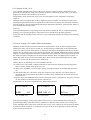
1
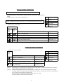
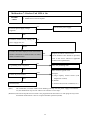
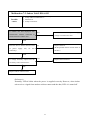
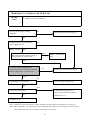
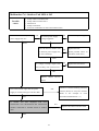
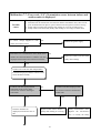
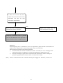
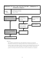
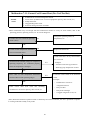
ORSUK0919 Operation Manual for Transmission Monitor RSUK0919 ENGLISH CHINESE JAPANESE AFTER SALES SERVICE DIVISION GLOBAL SERVICE DEPT, Operation Manual for Transmission Monitor RSUK0919 DAIKIN INDUSTRIES, LTD. AFTER SALES SERVICE DIVISION GLOBAL SERVICE DEPT, 1 Contents 1㧚Application ............................................................................................................................................... 4 2㧚Outline ...................................................................................................................................................... 4 3㧚Applicable models .................................................................................................................................... 4 Applicable/non-applicable model list ....................................................................................................... 5 4. Connection method to product.................................................................................................................... 7 5. Operation method ....................................................................................................................................... 8 6. Transmission Monitor display .................................................................................................................... 9 6-1 Contents of line 1 ............................................................................................................................... 9 6-2 Contents of line 2 to 4 ...................................................................................................................... 10 6-3 Line 4 on page 1 for outdoor/indoor units display ........................................................................... 10 6-4 Meaning of Abbreviation ................................................................................................................. 11 7. Problem diagnosis..................................................................................................................................... 12 Procedure of Indoor Unit Diagnosis ....................................................................................................... 13 8. Check method of microcomputer software version built in transmission checker ................................... 30 2 Transmission Monitor has advantages as follows, which will allow to prevent incorrect diagnose and reduce man-hours for maintenance. 1. Make it possible to check transmission data between indoor unit and outdoor unit. 2. Make it possible to check error code during retry operation. 3.Make it possible to check thermistor detection temperature and various control modes. 4. Easily access to data from indoor unit, which is convenient if ourdoor unit installation condition is improper or on a rainy day 5. Light weight and easy for installation 6. Power is supplied from product, which does not require extra power source or battery. 3 1㧚Application This operation manual describes Transmission Monitor RSUK0919 (hereinafter referred to the Transmission Monitor) developed by Daikin Industries, Ltd. 2㧚Outline Daikin’s air conditioners carry out communication between indoor and outdoor units. The communication data can serve as very useful information when conducting problem diagnosis. Transmission Monitor RSUK0919 received the data to indicate it on LCD. The Transmission Monitor is featured as follows. (1) Since the power supply is provided from the product to be monitored, no extra power supply, battery, etc. is required. (2) Applicable to voltage ranging from 100V to 240V (50/60 Hz). (3) Since the changeover of transmission methods is automatically judged, users are only required to connect the Transmission Monitor to the product. (4) IN/OUT Changeover Switch : Serves to switch the sender (Outdoor or Indoor unit Maximum four indoor units may be connected depending on the circumstances) of data to be displayed. (5) Display Changeover Switch : Serves to switch pages displaying the data. (6) The data can be displayed in Japanese or English, which can be switched by an internal jumper. (Factory setting is English) 3㧚Applicable models The Transmission Monitor is applicable to products performing the data transmission between indoor and outdoor unit through three- wire system among sprit & multi air conditioners and Skyair units developed by Daikin Industries, Ltd. -Representative models of applicable/non applicable models are shown in the list in the next page. All models cannot be described in the list. To judge whether the model is applicable or not, confirm the wiring diagram of product. -Reference wiring diagram is shown in the page 6. -Figure 1 and 2 show examples of applicable model. Figure 3 shows an example of non applicable model. Even the product performs data transmission through 3-wire system, it cannot be determined as an applicable mode when ON/OFF operation is controlled by relay circuit. -The models carrying out transmission of digital communication with transmission circuit and receiving circuit using photo-triac and photo-coupler (see figure 1) are applicable models. 4 Applicable/non-applicable model list Example of applicable model (room air conditioner) Example of non applicable model (room air conditioner) Model Name 2/3/4MK to FV 2/3/4MX to HV CDK25 to 60HA CDK25 to 60HV CTK to FV FTK(D) to JV FTX35/50HV FTX50HA FTY50GA FTY to 3B FTY to 3C FTY to D7 FTY25 to 60F (G) V FVY to 3C MY to C (J) RKD50 to 71JV RX50JV RX35/50HV RY RY to C RY to D7 RY25 to 60F(G)V RY50GV Model Name ANW to GV1 ARW to GV1 FHC to C FL13HV FT to 1B FT to C FT to F FT to EB FT25G FT50GAVE FT60CV FTY to A(B) FV to CJ MA to CJ MA to E MA28 to 90C MY to B R to E R to FV1 R to F R25G R13HV R50GV Sales start 1997 1999 2001 1999 1997 2001 1998 2000 2001 1994 1992 1993 1998 1992 1994 2000 2000 1998 1994 1992 1993 1998 2001 Example of applicable model(Skyair) Model name FAY71 to F FHK to F FHK35 to 71FV1 FHYB to DA FVY to DA FHYC to DA FHYK to DA FHY to DA FHYC to KVE FHYC50 to 125K FUJ71 to 125FJ FUY71 to 125FJV1 R125 to 250KU R71 to F RY to F R71 to KU RY35 to FV RY to DA RY35 to 60C RY to D RY50 to GV1A Double/twin/triple Sales start 1999 1999 1993 1999 1995 1992 1997 1997 1998 2001 1991 1991 1993 1993 1998 1992 1992 1995 1995 1997 1998 1999 2001 Example of non applicable model (Skyair) Sales start 1996 1996 2000 1994 1992 1992 1992 1992 2000 2001 1999 2000 2001 1995 1995 2000 2000 1994 1992 1992 2000 2001 Model name FAY71B FH to 60F FH35 to 60FV FHB35 to 60FV1 FH to C FHC 71 to C FHJ to B FHC to FU FHC35 to 60KVE FHK to BB FHY to LE FV to B FHS to BA R to 60B (-K) R to C R to BB RU to J R to DA7 R to FU R35 to 60GV1 R to 60F RY to DTGU 5 Sales start 1994 1995 1999 2000 1992 1995 1991 1997 2000 1992 1992 1992 1992 1996 1992 1992 1992 1993 1997 2000 1995 1994 Figure 1 Transmitting photo triac Receiving photo-coupler Figure 2 TC㧦Transmission circuit RC㧦Receiving circuit Figure 3 6 4. Connection method to product Basically, Transmission Monitor should be connected to the communication wires (3 wires) of indoor and outdoor units. As for some RA products produced in and after 2001, assignment of transmission wire has been changed from No. 2 to No.3 of the terminal block. Therefore, the connection method should be selected from the following two methods according to the models applied. It is recommended to measure the voltage to determine the connection method. Take Connection method 1 when the power supply voltage is impressed between connection wire 1-3, and Connection method 2 when the power supply voltage is impressed between connection wires 1-2. However, since connection method cannot be determined with voltage measurement when any malfunction in communication wiring or in transmission is occurred, it is required to confirm with wiring diagrams or those in service manual. 1. Connection method 1 (Power Supply1 to 3) When power supply 1 to 3. Connection Transmission Meaning of wire/ No. of monitor wiring wiring product Power supply 1 A(Red) Signal 2 B(White) (between connection wire 2 to 3) Power supply 3 C(Black) 2. Connection method 2 (Power Supply1 to 2) When power supply 1 to 2. Connection Transmission Meaning of wire/ No. of monitor wiring wiring product Power supply 1 A(Red) Power supply 2 C(Black) Signal 3 B(White) (between connection wire 2 to 3) Caution: Connection method 1(Power Supply 1 to 3) Indoor Unit A B Transmission C Monitor 1 2 3 Outdoor Unit Connection method 2 (Power Supply 1 to 2) Indoor Unit A B C 1 2 Transmission Monitor 3 Outdoor Unit A Incorrect connection (incorrect wiring) may not damage the Transmission Monitor or the product itself but may cause transmission error. The short-circuited clip of Transmission Monitor could result in damage of the components of product. Therefore, care should be taken for the positive connection. Be careful for short circuiting caused by the Example of connection to out door unit Example of connection to indoor unit 7 5. Operation method Turn the power on to the product after connecting the Transmission Monitor according to “4.Connection method to product". After five seconds, the product starts communication between indoor and outdoor units. The Transmission Monitor automatically judges the communication method to display the received data on LCD. The user selects the sender of signal to be monitored with the use of IN/OUT changeover switch, (select indoor unit to monitor the indoor temperature, or outdoor unit to monitor compressor operating frequency of outdoor unit) and then select pages that display the required data using of Display changeover switch. Page No. is displayed by xP on the upper right of LCD. The number of pages depends on the transmission method applied (e.g.1 or 7). The LCD display examples are shown below. Indoor unit in pair system is displayed on INDOOR 1. Sender Out-DrComp=OFF 1P INV:MultiHTpump OutDr=HEAT ALARM =H8 ψ INDOOR 0 COOL 1P Capacity=1.8kW TYPE=Wall Mount ERROR CODE =C3 ψ Display for indoor unit 0 (master unit) Display for outdoor unit INDOOR 1 STOP 1P Capacity=3.2kW TYPE=Floor Mount No Error Display for indoor unit 1 (slave unit) Line 1 indicates the sender and its operating status. Whenever pushing the IN/OUT changeover switch, the display changes from "Out-Dr" to "INDOOR 0" to "INDOOR 1" ̖,then "Out-Dr". Indoor unit in pair system is displayed at "INDOOR 1". "INDOOR 0" displays only for the master unit (remote controller connected units) of multiple systems including twin, triple, double twin, etc. Page No. Out-DrComp=OFF 1P INV:MultiHTpump OutDr=HEAT ALARM =H8 Display for Page 1 ψ Out-DrComp=OFF 2P Frequency= 48Hz HPS =Normal Display for Page 2 ψ Out-DrComp=OFF 3P OutDrTH= 35.5 㩩 C HeatEX = 7.0 㩩 C DischTH1= 75.0 㩩 C Display for Page 3 The LCD does not display data not received. The line 1 displays the sender and its status and switching page can not change the data displayed. The line 2 and 3 change displaying data whenever pressing the Display changeover switch. There may be blank line partially when any data has not been received to be displayed in the line. In some case, data ca not be received due to different type sending data depending on model or transmission version. 8 6. Transmission Monitor display Since the number of letters to display on the LCD of Transmission Monitor is limited, abbreviations are used to display the data. This chapter explains what the display indicates. The LCD can display 4 lines × 16 letters. “line x” in this document should be read as 1st line, 2nd line. from the top, and the bottom line as line 4. Line 1 Line 2 Line 3 Line 4 ψ ψ ψ ψ Out-DrComp=OFF 1P INV:MultiHTpump OutDr=HEAT ALARM =H8 6-1 Contents of line 1 Line 1 displays the sender of the data (outdoor unit, master unit of indoor unit, slave unit of indoor units and their number) its operating status, and the page number of data displayed. Data on the line 1 does not change even when switching the page displayed. (Section underlined in the tables below is the same on every page.) Page No. Out-DrComp=OFF 1P 㧦 㧦 㧦 ψ Out-DrComp=OFF 2P 㧦 㧦 㧦 ψ Out-DrComp=OFF 3P 㧦 㧦 㧦 For indoor units, the following numbers indicate No. of connected indoor units. For Skyair using a new refrigerant (R407C) in twin, triple, and double twin multi system, the LCD displays indoor unit with remote controller connected at "INDOOR 0", and others at "INDOOR 1to 3". However, for Skyair using a R22 refrigerant in twin, triple, and double twin multi system, the data of slave unit of indoor unit cannot be distinguished from the transmission data. Therefore, the LCD displays all indoor units at "INDOOR 1". (See Chapter 7-12.) For pair systems, the LCD displays the unit at "INDOOR 1". No data is displayed at "INDOOR 0". Sender Out-DrComp=OFF 1P 㧦 㧦 㧦 ψ INDOOR 0 COOL 1P 㧦 㧦 㧦 Master unit in twin multi system, etc. is displayed at "INDOOR 0". 9 ψ INDOOR 1 STOP 1P 㧦 㧦 㧦 Indoor unit in pair system is displayed at "INDOOR 1". 6-2 Contents of line 2 to 4 Line 2 through 4 displays data received. However, since the position to display the data received is specified (for example, the compressor operating frequency is displayed on page 2 line 2), no data is displayed on the line when the data is not received. Exceptionally, when transmission error occurs, the data appears on line 4 regardless of the page. Caution 1: Although some meaningless data could be displayed, ignore such data. For example, the data on the liquid pipe temperature thermistor is displayed on indoor unit in RA pair system sometimes. However, since the product is not equipped with the liquid pipe temperature thermistor, ignore the data. (Refer to heat exchanger thermistator value) Caution 2: If incompatible data between operating status and checker is displayed, that is, if required operating frequency=F13 (operating frequency instruction on level 13)and direct operating frequency instruction=0Hz are displayed at the same time, carry out problem diagnosis checking actual operating conditions. 6-3 Line 4 on page 1 for outdoor/indoor units display Malfunction data indicated on remote controller is displayed here. Since the data is displayed with malfunction codes, refer to service manual, etc. for the meaning of malfunction codes. Problems that occurred in indoor unit are indicated only on the indoor unit display, and malfunctions that occurred in outdoor unit are indicated only on the outdoor unit display. For example, although the remote controller displays C9 (indoor temperature thermistor malfunction), the malfunction code is displayed as 00 when the outdoor unit data is displayed on the Transmission Monitor. Since A5 (High pressure control) is a failure that could occur on indoor and outdoor units, the use of the Transmission Monitor can judge whether A5 comes from the indoor unit or outdoor unit. Further, there is the following level in the malfunction codes. (1) Caution error “CAUTION”: Outputs malfunction code but let the unit keep running (clogged air filter, overtime of filter cleaning set time, etc.) (2) Alarm error “ALARM”: Anyway, keeps running. Frequent actuation of ALARM stops the unit to run. (3) Thermostat-OFF error “Th-off Er”: Stops the compressor once and carry out control similar to thermostat OFF control. When the problem is released, resets automatically (Overload, Freeze-up protection, etc.) (4) System down error “ERROR”: Does not reset unless the system is stopped once, the power is turned off, the problem is released by the remote controller, etc. The difference in the level is displayed on the Transmission Monitor. Out-DrComp=OFF 1P 㧦 㧦 ALARM =H8 Out-DrComp=OFF 1P 㧦 㧦 ERROR CODE =C3 Out-DrComp=OFF 1P 㧦 㧦 No Error For ALARM error For system down For normal operation With regard to handling of the product against the error level, various detailed control methods are applicable depending on the characteristics (difference in RA/SA) of the product. (For example, the system should be down at how many times the error occurs, or the counting of error occurrence should be cleared in which condition, etc.) Therefore, the error level can be recognized as a target when the actual servicing is carried out. 10 6-4 Meaning of Abbreviation Transmission from outdoor unit to indoor unit Abbreviations in English Active ALARM CAUTION Comp TH Cool Current DEFROST Disch P DischTH1 DischTH2 DRY ERROR CODE FIN TH Frequency HEAT Heat EX Hot Only HPS Abbreviations in English Htpump INV Multi no data No Error Non: Normal OPERATION Out Fan Out Fan1 Out Fan2 OutDr OutDrTH Pair STOP/Free SuctionTH Th-off Er Meaning ON ON CAUTION ERROR Compressor head temperature Cooling only unit Input current In defrost operation Discharge pressure Discharge temperature 1 Discharge temperature 2 Dry operation Malfunction code Radiation fin temperature Compressor operating frequency Heating operation Heat exchanger temperature Heating only unit High pressure protection device Meaning Heat pump Inverter Multi system No data No malfunction Non-inverter Normal reset䋨normal status䋩 In operation Outdoor unit fan Speed of outdoor unit fan1 Speed of outdoor unit fan2 Outdoor unit Outdoor temperature Pair system In stop mode Suction temperature Thermostat-OFF error Transmission from indoor unit to outdoor unit Abbreviations in English ACT Actuate Built in ON ON Built-in type Built in Hi Built-in Hi type Capacity Ceil Casset CeilCasset2 CeilConceal CeilSuspend Circulator CMDto NextRM Cntrl TH Concealed COOL Cooling capacity Ceiling mounted cassette type Ceiling suspended, double flow type Ceiling concealed type Ceiling suspended type Circulator With command to next room Remote controller temperature Concealed type Cooling operation Corner Corner type DEMAND Demand Abbreviations in English LEVEL LevelH LevelL Liquid Th Meaning Low Noise NewWallMont NoCMD toNEXT Non OFF ON Out FAN CMD Out-DrComp P0䌾P6 PeakCut PeakCut/Freez=OK PeakCut/Frez=ACT ERROR CODE Difference between remote controller set PMT value and room temperature. Dry operation PowerSave PowerSelect Malfunction code FAN Fan operation FAN Fan operating status Flap Flap status Floor Mount Floor mounted type FloorCnceal Floor concealed type Forced Thrmo Forced thermostat OFF FreezPRT In freeze-up protection status Heater HOT HOT WT HtEX Th HtEx Th2 INDOOR IntakeTH Jet TH Heater Heating operation Hot water supply operation Indoor unit heat exchanger temperature Indoor unit heat exchanger 2 temperature Indoor unit Indoor unit suction temperature Indoor unit discharge temperature dif tmp DRY PRT Req realHz Required Hz Room Th SubUNIT Prot SubUNIT PrtctACT SubUNIT_Prtct=OK 11 SW Thermo TYPE unknown Venti. Wall Mount WallConceal Meaning Operation level Level high Level low Indoor unit liquid pipe temperature (for multi system) Low noise instruction New wall mounted type No command to next room Non Not activated ON Demand for outdoor unit fan Status of outdoor unit compressor Flap position Peak cut status Peak cut and freeze-up protection are not activated (normal) Peak cut and freeze-up protection are activated.䋨malfunction䋩 Permission Power save Current restriction by power selection Prohibition Direct operating frequency instruction Indoor unit demand operating frequency Room temperature Slave unit in peak cut and freeze-up protection status Peak cut and freeze-up protection actuated on slave unit (malfunction) Peak cut and freeze-up protection for slave unit in normal status Swing status Thermostat demand Type Unknown Ventilation operation Wall mounted type Wall concealed type 7. Problem diagnosis Since the respective model has its own characteristics, all problem diagnosis cannot be described in details. This chapter describes typical diagnosis (in which the Transmission Monitor is used effectively) for individual cases. In the chart, the inspection item which is not possible or difficult without Transmission Monitor is indicated in color . Especially, to diagnose for maintenance relating transmission such as ON/OFF operation of LED and “Error U4”, connection wire inspection is required in the first stage, which does not make sense if no malfunction is found out. Transmission Monitor enables to distinguish malfunction in internal/external PCB and communication wire and diagnosis is carried out synchronously with the function. Since an incorrect diagnosis may be occurred when using only LED data, it is required to carry out diagnosis confirming the judgement by using the data of the Transmission Monitor. Possible cause is described in the order of frequent occurrence. Reference sheet: Procedure for Indoor unit and outdoor unit diagnosis by LED Diagnosis by LED 7-1:Indoor Unit LED-A On 7-2: Indoor Unit LED-A Off 7-3: Indoor Unit LED-B On 7-4: Indoor Unit LED-B Off 7-5:Outdoor Unit LED-A On 7-6:Outdoor Unit LED-A Off Malfunction code diagnosis 7-7: Malfunction code “U4” is displayed. 7-8: Malfunction Code “A5” (Overload/Freeze-up Protection) is displayed 7-9: Malfunction code “C4”,”C9”,”J6”,”H9” (Malfunction of thermistors) is displayed. 7-10: Malufunction code “U0” is displayed. Other diagnosis 7-11: Cannot Cool/Cannot Heat (Too Cool/Too Hot) 7-12: Problem Diagnosis for Skyair Twin/Triple/Double twin multi-unit using a R22 refrigerant 7-13: Water leakage occurs under a certain condition. 7-14: Noise occurs from compressor (main unit). 12 Procedure of Indoor Unit Diagnosis STEP 1: Diagnosis of incorrect or disconnected transmission wiring If LED-B (green) on indoor unit PC board is off, the transmission wiring between indoor and outdoor unit is incorrect or disconnected. Green Blinks when normal LED on STEP 2: Diagnosis of other than incorrect or disconnected transmission wiring <Indoor unit PC board LED> 䃂 䋭 LED off LED blinks No connection with diagnosis Green Micro Computer Normal Monitor LED-A Transmissio Normal Monitor LED-B Contents Diagnosis method 䋭 Normal 㸢 Outdoor unit 䃂 䋭 (Note) Malfunction 7-1 䋭 Malfunction of power supply or (Note) Malfunction 7-2 Faulty indoor unit PC board Malfunction 7-3 If outdoor unit’s LED-A blinks, faulty indoor unit PC board Malfunction 7-4 䃂 (Note) If the LED display is reproduced by turning on the power supply, indoor unit PC board is faulty. Procedure of Outdoor Unit Diagnosis <Outdoor unit PC board LED> Micro Computer Normal Monitor LED-A Green Blinks when normal LED on Contents Diagnosis method Normal 㸢 Indoor unit 䃂 㸢䃂 䃂 LED off 䋭 LED blinks No connection with diagnosis 䋭 (Note 1) Malfunction 7-5 Malfunction of power supply or (Note 2) Malfunction 7-6 Blinks right after the power supply is turned on, Malfunction 7-6 then off after that. (Note 1) If LED display is reproduced by turning the power supply back on, outdoor unit PC board 1 is faulty. (only on unit equipped with PC board 1 and 2) (Note 2) If LED display is reproduced by turning the power supply back on, when turning the power supply off again and then turning the power supply back on with the transmission wire No.2 disconnected (No. 1 and 3 are power supply voltage units.) If LED-A goes out, outdoor unit PC board (See Note 1) is faulty. If LED-A blinks, indoor unit PC board faulty. 13 Malfunction 7-1:Indoor Unit LED-A On Possible causes Ԙ Faulty indoor unit PC board ԙ Malfunction of microcomputer Is correct power supply voltage NG Recheck the power supply. supplied? OK Is LED-A turned on by turning the ON power supply back on? Blinks Is indoor unit data displayed with transmission monitor connected to terminal board of either NO Replace the indoor unit PC board. (If two numbers of PC boards are provided, indoor or outdoor unit? refer to the service manual of applicable YES model for the replacement.) NG Carry out grounding work. Is grounding work completed? OK Take measures against noise. YES Example: Is there any noise source? a) Large capacity electric heater (with temperature control) NO b) Welder c) Inverter fan (used for ventilation, etc.) Normal (Note) (Note) Be careful that, even when LED-A starts blinking normally after the power supply is turned back on, this malfunction may reoccur within a few minutes to a few days. (Reference) The microcomputer for PC boards is not programmed to turn LED-A on. The program may not be functioned while LED-A is ON as it repeats ON/OFF operation (blinks). 14 Malfunction 7-2: Indoor Unit LED-A Off Ԙ ԙ Ԛ ԛ Possible causes Incorrect power supply voltage or faulty transmission wire Faulty indoor unit PC board Molten fuse Faulty transformer Is outdoor unit data displayed with transmission monitor connected to Check and correct the power supply NO voltage or transmission wire. terminal board of indoor unit? YES Does the fuse on indoor unit PC board or power supply line, etc. Replace the fuse. NO (Probe possible causes of melt down of has the fuse.) continuity? YES Is voltage normally output from the NG Replace the transformer. secondary side of transformer? OK Replace indoor unit PC board. (Reference) Normally, LED-A blinks when the power is supplied correctly. However, when indoor unit receives a signal from outdoor unit but cannot send the data, LED-A is turned off. 15 Malfunction 7-3: Indoor Unit LED-B On Ԙ Faulty indoor unit PC board Possible causes Replace indoor unit PC board. (Reference) LED-B displays the sent data transmitted between indoor and outdoor unit. Since LED-B cannot be turned on, faulty PC board is suspected. 16 Malfunction 7-4: Indoor Unit LED-B Off (LED-A Blinks) Possible causes Ԙ Faulty transmission wiring ԙ Faulty outdoor unit PC board Ԛ Faulty indoor unit PC board (Reference) Since this malfunction relates to outdoor unit very much, diagnose together with Malfunction 7-5 and 7-6. If the outdoor unit can be easily checked, it is recommended to check of outdoor unit LED-A first to start diagnosing with the outdoor unit. Is outdoor unit data displayed with Faulty outdoor unit PC board NO transmission monitor connected to Faulty transmission wire terminal board of indoor unit? To Malfunction 7-6 YES Check for indoor unit data without connection change. Not displayed Replace indoor unit PC board. (Reference example) LED-B is turned off sometimes. (Other LED blinks normally.) Does LED-B break blinking sometimes? NO Normal YES Noise entered the power supply line. (Refer to the example of noise described in Malfunction 7-1.) 17 Malfunction 7-5: Outdoor Unit LED-A On Possible causes Ԙ Faulty outdoor unit PC board ԙ Malfunction of microcomputer Is correct power supply voltage supplied? NG Recheck the power supply system. OK Is LED-A turned on by turning the power supply back on? Blinks (normal) ON OFF Blinks Does LED-A blinks with No.2 (Note 1) transmission wire disconnected? Faulty transmission wire OFF Is outdoor unit data displayed with transmission monitor connected to terminal board of either indoor or outdoor unit? NO Replace the outdoor unit PC board. YES NG Carry out the grounding work. Is grounding work completed? OK YES Take measures against noise. Is there any noise source? (Refer to the example described in NO Malfunction 7-1.) Normal (Note 2) (Note 1) This No.2 means that the wire is other than that of power supply line. Therefore, it can be No.3 (Note 2) Be careful that, even when LED-A starts blinking normally after the power supply is turned back on, this malfunction may reoccur within a few minutes to a few days. 18 Malfunction 7-6: Outdoor Unit LED-A Off Ԙ ԙ Ԛ ԛ Ԝ ԝ Possible causes Incorrect power supply voltage or faulty transmission wire Faulty outdoor unit PC board Faulty indoor unit PC board Molten fuse Faulty transformer Incorrect combination of indoor and outdoor units Is LED-A turned off by turning OFF power supply back on? Recheck the power supply. NG Is correct power supply voltage supplied? OK Blinks Does the fuse on outdoor unit PC board or power supply line, Replace the fuse. NO (Probe possible causes of etc. has continuity? melt down of the fuse.) YES Is voltage normally output from NG Replace the transformer. the secondary side of transformer? OK Replace outdoor unit PC board. If LED-A continues blinking after that, NO Does LED-A blink right after the power normal. (Noise, etc. may have entered. supply is turned on and goes out after that? Refer YES Is outdoor unit data to the example of noise described in Malfunction 7-1.) displayed with No.2 NO transmission wire disconnected and transmission monitor connected to terminal board of outdoor unit? YES 19 Replace the outdoor unit PC board. Hereafter, diagnose referring to Malfunction 7-7. Faulty transmission wire Faulty indoor unit PC board Incorrect combination of indoor and outdoor units (Note 1) This No.2 means that the wire is other than that of power supply line. Therefore, it can be No.3 20 Malfunction 7-7: Error code “U4” (Transmission error between indoor and outdoor units) is displayed. Possible causes Ԙ No power supply to indoor or outdoor unit ԙ Disconnection in transmission wire between indoor and outdoor units, short circuit, poor insulation between phases, poor insulation unit and ground, incorrect wiring Ԛ Faulty indoor unit PC board (Faulty data sending or receiving of indoor unit ) ԛ Faulty outdoor unit PC board (Faulty data sending or receiving of outdoor unit) Is correct voltage supplied to both NG Recheck the power supply. indoor and outdoor units? OK Disconnect No.2 transmission wire (Note) from NO outdoor unit terminal board. Is outdoor unit data Replace the outdoor unit PC board displayed with transmission monitor connected? (faulty data sending) YES Outdoor unit sends the data independently. If the data displayed, outdoor unit PC board sends the data normally. Is indoor unit data displayed with connection of No.2 wire while transmission monitor unchanged connected? NO Is outdoor unit data displayed with transmission monitor connected to indoor unit? YES If indoor unit data can displayed, transmission wire is OK. YES NO Replace indoor unit PC board. Faulty transmission wire. (Faulty data sending or receiving) Replace the transmission wire or remedy the faulty 21 If indoor unit received data from outdoor unit, indoor unit sends some information and does not send information independently. Error code “U4” is displayed on the YES Replace the outdoor unit PC transmission monitor at all times. board. (Faulty data receiving) NO Temporary transmission error is possible. Wait for the malfunction to be displayed on the transmission monitor to diagnose again. (Reference) When diagnosing the “U4” malfunction, since it is impossible to judge which PC board of indoor or outdoor unit is faulty, both PC boards are replaced in most cases at present. The transmission monitor has the following benefits. Ԙ When the indoor unit cannot communicate for about 15 seconds, the “U4” is displayed. The transmission monitor can display it even when an instantaneous malfunction occurs. ԙ Since the exchange of signals can be monitored on the transmission monitor visually, it is possible to judge which PC board of indoor or outdoor unit is faulty. (Note) This No.2 means that the wire is other than that of power supply line. Therefore, it can be No.3 22 Malfunction 7-8: Error Code “A5” (Overload/Freeze-up Protection) is displayed Possible causes Ԙ ԙ Ԛ ԛ Ԝ Dirty indoor unit filter or heat exchanger Faulty thermistor Insufficient or excessive refrigerant amount Clogged refrigerant circuit Local causes (cooling in low outside air temperature, heating in high temperature, short circuit, etc.) ԝ Faulty PC board 㧖Since information may not enough with the transmission monitor to verify on some models, refer to the operating pressure, operating current, etc. as well for diagnosis. Is the unit operating beyond the Explain the specified range for continuous operation to improve the operating conditions. YES specified range? NO Replace Is value of each temperature thermistor NG the thermistor. (If the malfunction is not remedied even when the thermistor is replaced, close to measured value? replace the PC board.) OK Does value of each temperature thermistor NO Locate the causes based on the abnormal value. remain within normal operating range? Example: Insufficient or excessive YES refrigerant amount Probe causes other than main unit including insufficient Dirty air filter or excessive capacity, short circuit, etc. Dirty heat exchanger Clogged refrigerant circuit, etc. (Reference) The error code “A5” (Overload/Freeze-up Protection) is detected by the indoor unit heat exchange thermistor and outdoor unit heat exchange thermistor. Check for the reading of microcomputer with the transmission monitor while measuring the temperature through the heat exchanger thermistors. If both temperatures are coincided, probe real causes to actuate the overload control. 23 Malfunction 7-9: Error code “C4”,”C9”,”J6”,”H9” thermistors) is displayed. Ԙ ԙ Ԛ ԛ Possible causes (Malfunction of Faulty thermistor Disconnection of connector Poor soldering of PC board Faulty PC board Is value of each temperature thermistor close to measured NG value? Are connectors of NG Securely connect the thermistor securely connectors to check connected? operation. OK OK Is PC board soldered NG Repair soldering. properly? (connector section of thermistor) OK Is abnormal value shown when exceeding a certain temperature YES Replace the thermistor. during operation? NO Replace the PC board. (Reference) This malfunction is automatically reset. If the malfunction is present even in stop mode, disconnection of thermistor, poor soldering inside PC board, or affixed foreign matter, etc. are presumed. Judge by measuring the resistance of thermistor. If the malfunction has been reset when servicing, operate the unit while comparing the actual temperature measured at the thermistor position to the reading of the transmission monitor to check for the difference in temperature. 24 Malfunction 7-10: Error code “U0” (Refrigerant shortage) is displayed. Possible causes Ԙ ԙ Ԛ ԛ Ԝ Refrigerant shortage Clogged refrigerant circuit Faulty thermistor Faulty compressor (inverter type only) Faulty PC board 㧖“U0” is decided when the compressor operating frequency exceeds a certain frequency (that varies depending on the model) while low current continues or when there is no difference in temperature between indoor and outdoor heat exchangers. Measure the compressor operating frequency and temperature of each section with the transmission monitor, and actual value of current, temperature at the thermistor section, gas pressure, etc. to compare the values and probe the causes. Replace the thermistor. (If the Is value of each temperature thermistor malfunction is not remedied even NG when the thermistor is replaced, close to measured value? replace the PC board.) OK Does refrigerant leak? Repair the leaking point and YES charge the specified amount of refrigerant NO Is refrigerant circuit clogged? YES Repair the clogged point of refrigerant circuit. NO Change the set temperature. Do pressure, pipe temperature, andǍT㧔㧖㧕vary properly Does the faulty NG compression occur? in accordance with the change of the (Conduct pump down compressor operating frequency? operation to check.) OK NO Check refrigerant circuit once again. 㧔㧖㧕 Difference between the suction and discharge temperatures of indoor unit 25 YES Replace the compressor Malfunction 7-11: Cannot Cool/Cannot Heat (Too Cool/Too Hot) Possible causes Ԙ ԙ Ԛ ԛ Ԝ ԝ Dirty filter (heat exchanger) Insufficient or excessive refrigerant amount Local causes (insufficient or excessive equipment capacity, short circuit, etc.) Faulty thermistor Clogged refrigerant circuit Incorrect setting of remote controller 㧖Since information may not enough with the transmission monitor to verify on some models, refer to the operating pressure, operating current, etc. as well for diagnosis. Change the operating mode, set Is indoor unit set to desired operating NG temperature, etc. mode? (Note) OK NG Is value of each temperature thermistor Replace the thermistor. close to measured value? OK Check if the unit is in any control mode for correction Are thermostat ON/OFF, change in compressor 㧺㧳 operating frequency, etc. conducted properly Example: Actuation of freeze-up protection when set temperature is changed. Discharge pipe temperature control OK Does value of each temperature thermistor 㧺㧳 Locate the causes based on the abnormal value. remain within normal operating range? Example: OK Insufficient or excessive refrigerant amount Probe causes other than main unit including insufficient or excessive capacity, short circuit, etc. Dirty air filter Dirty heat exchanger Clogged refrigerant circuit, etc. (Note) When the automatic operation mode is selected by the remote controller, the unit is presumed to operate in cooling mode but actually in dry mode. 26 Malfunction 7-12: Problem Diagnosis for Twin/Triple/Double twin multi-unit of Skyair using a R22 refrigerant Possible cause This system is provided with several indoor units, which are defined as master unit (with remote controller connected)and as slave unit. On the Transmission Monitor the master unit is displayed as ″INDOOR 0″, and the slave unit as ″INDOOR 1″. However, regarding the slave unit, the Transmission Monitor cannot judge from which slave unit the error is sent and displays as ″INDOOR 1″. Since the master unit manages all controls in normal operation, such display matters little. But when malfunction occurs (for example when float switch malfunctions on any of slave units), the slave unit where the float switch malfunctions cannot be located, because the malfunction code is sent once in 5-10 minutes when monitoring the slave unit only. The Transmission Monitor displays the error instantaneously. But when the Transmission Monitor receives the normal data from a slave unit after several minutes, it displays ″No Error″ and maintains the normal display until it receives the data from slave unit that malfunctions again. Further, when a critical error such as actuation of float switch occurs, the Transmission Monitor cannot locate which indoor unit malfunctions because the master unit sends the error data to the outdoor unit after it receives the error data of the slave unit. Eventually, there is no other method than to inspect all indoor units for triple multi or double twin multi system. However, the transmission method is changed for twin/triple/double twin multi system applying a new refrigerant (R407C). Individual address is given to respective slave unit to display as ″INDOOR1″, ″INDOOR 2″ and ″INDOOR 3″ on the Transmission Monitor. With these units, it is possible to identify which indoor unit corresponds to ″INDOOR 1″ or ″INDOOR 2″ by purposely generating a different malfunction (for example, to activate the float switch). R22 Refrigerant Unit R407c Refrigerant Unit Outdoor Unit INDOOR㧜 Outdoor Unit INDOOR㧝 INDOOR㧝 INDOOR㧜 When malfunction occurs on slave unit, it is difficult to locate the faulty unit. INDOOR㧝 INDOOR㧞 When malfunction occurs on slave unit, it is easy to locate the faulty unit. 27 Malfunction 7-13: Water leakage occurs under a certain condition. Possible causes It may be difficult to reproduce water leakage under a certain condition at factory. Providing objective data can support to shorten the response time. Example: The following information can be transmitted. Ԙ Since the compressor operating frequency can be checked, “When the compressor conducts stable operation under operating frequency of ( )Hz and at heat exchange temperature of ( )͠, water leakage occurs.” ԙ “When the compressor operates under operating frequency of ( )Hz or lower, at outside air temperature of ( )͠ and heat exchange temperature of ( )͠, the drift of refrigerant occurs.” 28 Malfunction 7-14: Noise occurs from compressor (main unit). Possible causes It may be difficult to reproduce abnormal noise from compressor at factory. Providing objective data can support to shorten the response time. Example: The following information can be transmitted. Ԙ Since the compressor operating frequency can be checked, “Abnormal noise occurs when the compressor operating frequency reaches ( )Hz or higher.” ԙ Since various control modes are checked, “Liquid compression sound is heard at outdoor temperature of ( )͠ in defrost ON mode. Ԛ “Refrigerant passing sound occurs under compressor operating frequency of ( setting temperature of ( )͠ .” 29 )Hz at remote controller 8. Check method of microcomputer software version built in transmission checker When supplying power for the Transmission Monitor by pushing the IN/OUT changeover switch, the following display appears on LCD. Communication Monitor Vx.xx ععععععععععع ععععععععععع V2.00 is the latest version as of November 2001. 30