1
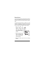
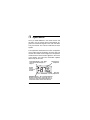
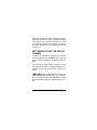
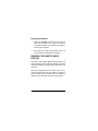
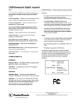
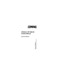
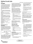
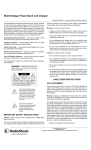
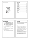
Please read before using this equipment. Owner’s Manual Wireless Indoor/ Outdoor Thermometer ˆ Contents FCC Information .................................................... 3 FCC Declaration of Conformity .......................... 5 Preparation ............................................................ 5 Installing Batteries ............................................. 5 In the Remote Sensor ............................... 7 In the Main Unit ......................................... 8 Mounting Options .............................................. 9 Selecting a Location ................................. 9 Main Unit ................................................. 10 Remote Sensor ....................................... 11 Operation ............................................................. Setting/Selecting the Display Channel ............ Scanning Channels ................................. Reading the Kinetic Wave Display ................... Checking Maximum/Minimum Temperatures ... Temperature Alarm .......................................... 12 13 14 14 15 15 Troubleshooting .................................................. 16 Manually Searching for a Signal ...................... 16 Resetting the System ...................................... 17 Care ...................................................................... 17 Specifications ...................................................... 18 2001 RadioShack Corporation. All Rights Reserved. RadioShack and RadioShack.com are registered trademarks used by RadioShack Corporation. 2 Contents ˆ Introduction Your RadioShack Wireless Indoor/Outdoor Thermometer with Wireless Remote Sensor is a complete system that lets you monitor the temperature indoors and out. You can hang the main unit indoors on a wall or use its built-in stand for easy viewing on a table. You can place the remote sensor outdoors or in another room to monitor the temperature at that location. You can use up to two other remote sensors (RadioShack Cat. No. 63-1027, not supplied) with the system’s three built-in remote channels to monitor the temperature at four different locations. ˆ FCC Information This equipment has been tested and found to comply with the limits for a Class B digital device, pursuant to Part 15 of the FCC Rules. These limits are designed to provide reasonable protection against harmful interference in a residential installation. This equipment generates, uses and can radiate radio frequency energy and, if not installed and used in accordance with Introduction 3 the instructions, may cause harmful interference to radio communications. However, there is no guarantee that interference will not occur in a particular installation. If this equipment does cause harmful interference to radio or television reception, which can be determined by turning the equipment off and on, the user is encouraged to try to correct the interference by one or more of the following measures: • Reorient or relocate the receiving antenna. • Increase the separation between the equipment and receiver. • Connect the equipment into an outlet on a circuit different from that to which the receiver is connected. • Consult your local RadioShack store or an experienced radio/TV technician for help. • If you cannot eliminate the interference, the FCC requires that you stop using your thermometer. Changes or modifications not expressly approved by RadioShack may cause interference and void the user’s authority to operate the equipment. 4 FCC Information FCC DECLARATION OF CONFORMITY This device complies with Part 15 of the FCC Rules. Operation is subject to the following two conditions: (1) this device may not cause harmful interference, and (2) this device must accept any interference received, including interference that may cause undesired operation. Product: Model: Responsible Party: Phone: Wireless Indoor/Outdoor Thermometer 63-1033 RadioShack 100 Throckmorton Fort Worth, TX 76102 817-415-3200 ˆ Preparation INSTALLING BATTERIES You need four AA batteries (not supplied) to power your thermometer. For the best performance and Preparation 5 longest life, we recommend RadioShack alkaline batteries. Warning: Dispose of old batteries promptly and properly. Do not burn or bury them. Cautions: • Use only fresh batteries of the required size and recommended type. • Do not mix old and new batteries, different types of batteries (standard, alkaline, or rechargeable), or rechargeable batteries of different capacities. • Always remove old or weak batteries. Batteries can leak chemicals that can destroy electronic parts. Notes: • If you expect to use the remote sensor in temperatures below –4°F (–20°C), we recommend you use lithium batteries in the remote sensor. • Install batteries in the remote sensor first, then in the main unit, to give the main unit time to find the sensor’s signal. 6 Preparation • When appears on the main unit’s top right display, replace the batteries in the remote sensor. • When appears on the main unit’s lower right display, replace the batteries in the main unit. In the Remote Sensor Your thermometer’s main unit can display information for up to three remote sensors. Additional remote sensors are available at your local RadioShack store. 1. Use a Phillips screwdriver to remove the screws from the battery compartment cover, then lift it off. 2. Place two AA batteries in the compartment according to the polarity symbols (+ and –) marked inside. Preparation 7 3. To select the degree format displayed on the remote sensor, set °C/°°F inside the remote sensor’s battery compartment to °C or °F. 4. Set CHANNEL 1/2/3 inside each remote sensor’s battery compartment to a different setting. 5. Using a pointed object (such as a straightened paper clip), press RESET to activate the sensor’s transmitter. 6. Replace the cover, then reinsert and tighten the screws. In the Main Unit 1. Remove the battery compartment cover by sliding it toward the top of the unit. °C/°F 2. Place two AA batteries in the compartment according to the polarity symbols (+ and –) marked inside. 8 Preparation RESET 3. To select the degree format displayed on the main unit, set °C/°°F inside the main unit’s battery compartment to °C or °F. 4. Using a pointed object (such as a straightened paper clip), press RESET inside the battery compartment to activate the main unit’s receiver. 5. Replace the cover. MOUNTING OPTIONS You can place the main unit and remote sensor on flat surfaces, or mount them on the wall. Selecting a Location Choose locations for the main unit and remote sensor that are within 60–90 feet of each other. The main unit should be located indoors, but the remote sensor can be placed either indoors or out. Your home or office’s construction might affect the transmission range between the main unit and the remote sensor. If you have a choice of several locations, try each to see which provides the best performance. Preparation 9 Cautions: • Do not place the main unit or remote sensor in direct sunlight, near electrical appliances, or near heating or air conditioning vents. • Do not place the main unit in a location where it is likely to get wet. Only the remote sensor is weather-resistant. Main Unit To set the main unit on a flat surface, rotate the table stand on the bottom of the unit clockwise until it clicks. To mount the main unit on a wall, you need a 1/8-inch (3-mm) screw (not supplied) with a head that fits the keyhole slot on the back of the main unit. 1. Drill a hole in the wall at the desired mounting location. 2. Thread a screw into the wall until the head extends about 1/4 inch from the wall. 3. Position the keyhole slot in the back of the main unit over the screw and slide the thermometer down to secure it. 10 Preparation Remote Sensor To set the remote sensor on a flat surface, insert the ends of the supplied wire stand into the holes on the back of the remote sensor above the battery compartment. To mount the remote sensor on a wall (or on a post outdoors, for example), you need two 1/8 inch (3-mm) screws (not supplied) with heads that fit the keyhole slots on the back of the supplied mounting bracket. 1. Drill two holes 13/4 inches apart. Then thread a screw into each hole, letting the heads extend about 1/4 inch from the mounting surface. 2. Align the keyhole slots on the mounting bracket with the screws and slide the bracket downward to secure it. 3. Slide the remote sensor into the mounting bracket. Preparation 11 ˆ Operation Once you install batteries in the remote sensor and the main unit, the remote sensor’s temperature appears and it transmits signals to the main unit about every 30 seconds. The main unit searches for those signals. The temperature measured at the main unit appears on the bottom right of the display. Once the main unit receives the remote sensor’s signal, the temperature measured at the remote sensor appears in the center of the display. The main unit’s information updates about every 30 seconds. Kinetic Wave Display — See “Reading the Kinetic Wave Display” on Page 14. Remote Sensor Temperature Remote Sensor Channel Number Main Unit Temperature MAX/MIN Indicator — See “Checking Maximum/ Minimum Temperatures” on Page 15. In this illustration, 87.4°F is the highest temperature recorded at the remote sensor set to channel 2. 12 Operation If the main unit does not receive (or stops receiving) a signal from the remote sensor, 0010# appears instead of a temperature. Try manually searching for a signal (see “Manually Searching for a Signal” on Page 16) or resetting the main unit (see “Resetting the System” on Page 17). SETTING/SELECTING THE DISPLAY CHANNEL To display the temperature information for a remote sensor, repeatedly press CHANNEL on the main unit until the channel number for the desired sensor appears. If you set two or more remote sensors to use the same channel, the main unit displays temperature information for the first remote sensor’s signal it receives. If +++ or ///#appears, the temperature is above or below the temperature display range (see “Specifications” on Page 18). When the temperature is again within the display range, the display returns to normal. Operation 13 Scanning Channels 1. Hold down CHANNEL for about two seconds. The main unit scans from one channel to another. The display updates the channel and temperature every five seconds. 2. Press any key to stop the automatic scan. The current channel and temperature appear. READING THE KINETIC WAVE DISPLAY The kinetic wave display appears directly above the channel number on the main unit’s display. The wave shows the status of the signal being received by the main unit. When the dot appears alone, the main unit is not receiving a signal. When the arcs appear one after another, the main unit is searching for (or receiving a signal from) the selected channel’s remote sensor. 14 Operation CHECKING MAXIMUM/MINIMUM TEMPERATURES The main unit stores the maximum (highest) and minimum (lowest) local temperatures and those of each remote sensor in its memory. 1. Repeatedly press CHANNEL on the main unit to select a channel. 2. Press MEM once to recall the maximum temperature (MAX) and again to recall the minimum (MIN) temperature. 0$; or 0,1 appears. 3. Press MEM again to return to the current temperature. To clear the maximum and minimum temperature memory for the main unit and the selected channel, press CLEAR. The display resets and the current temperatures appear. TEMPERATURE ALARM When the temperature recorded on channel 1 falls between –2°C (28.4°F) and 3°C (37.4°F), the main unit sounds an alarm every minute as long as the temperature stays within that range. The current outdoor temperature flashes. 15 Operation Press any key to stop the alarm. The outdoor temperature continues flashing until the temperature is out of that range or you change to channel 2 or 3. ˆ Troubleshooting MANUALLY SEARCHING FOR A SIGNAL If 0010# appears on the thermometer instead of a temperature, or a temperature different than that displayed on the selected channel’s remote sensor continuously appears, the main unit has stopped receiving a signal from the sensor. Press CHANNEL and MEM at the same time on the main unit to manually search for a signal. If the main unit still does not operate properly, try moving it or the remote sensor to a different location, or resetting the system. 16 Troubleshooting RESETTING THE SYSTEM If the main unit or remote sensor stop operating properly (and you have tried manually searching for a signal), use a pointed object (such as a straightened paper clip) to press RESET inside the main unit or remote sensor’s battery compartment. This resets all display elements and temperature settings. ˆ Care Keep the thermometer dry; if it gets wet, wipe it dry immediately. Use and store the thermometer only in normal temperature environments. Handle the thermometer carefully; do not drop it. Keep the thermometer away from dust and dirt, and wipe it with a damp cloth occasionally to keep it looking new. Modifying or tampering with the thermometer’s internal components can cause a malfunction and might invalidate its warranty and void your FCC authorization to operate it. If your thermometer is not performing as it should, take it to your local RadioShack store for assistance. Care 17 ˆ Specifications RANGE Main Unit Displayed Indoor Temperature ..................... 14.2°F to158°F (–9.9°C to 70.0°C) Operating Range ..................................... 23.0°F to 122.0°F (–5.0°C to 50.0°C) Displayed Outdoor Temperature Range .................................................... –58.0°F to 158.0°F (–50.0°C to 70.0°C) Accuracy ... ±2.0°F( ±1.0°C) at 32°F to 104°F (0°C to 40°C) ±4.0°F(±2.0°C) at –40°F to 122°F(–40°C to 50°C) ±6.0°F(±3.0°C) at –58°F to 158.0°F(–50°C to 70°C) Remote Unit Operating Range ................................... –22.0°F to 140.0°F (–30.0°C to 60.0°C) POWER Main Unit ..................................... 3V with Two AA Batteries Remote Sensor ........................... 3V with Two AA Batteries Note: At temperatures below –4°F(–20°C), use lithium batteries (Cat. No. 23–664) in the remote sensor. Temperature Resolution ................................. 0.2°F (0.1°C) WEIGHT (without batteries) 18 Specifications Main Unit ........................................................ 2.75 oz (78g) Remote Sensor .............................................. 3.5 oz (100g) DIMENSIONS Main Unit ....................................... 31/4 × 27/8 × 11/16 Inches (83 × 73 × 27.5mm) Remote Sensor .............................. 41/8 × 23/4 × 13/16 Inches (105 × 70 × 21mm) Specifications are typical; individual units might vary. Specifications are subject to change and improvement without notice. 19 Specifications Limited Ninety-Day Warranty This product is warranted by RadioShack against manufacturing defects in material and workmanship under normal use for ninety (90) days from the date of purchase from RadioShack company-owned stores and authorized RadioShack franchisees and dealers. EXCEPT AS PROVIDED HEREIN, RadioShack MAKES NO EXPRESS WARRANTIES AND ANY IMPLIED WARRANTIES, INCLUDING THOSE OF MERCHANTABILITY AND FITNESS FOR A PARTICULAR PURPOSE, ARE LIMITED IN DURATION TO THE DURATION OF THE WRITTEN LIMITED WARRANTIES CONTAINED HEREIN. EXCEPT AS PROVIDED HEREIN, RadioShack SHALL HAVE NO LIABILITY OR RESPONSIBILITY TO CUSTOMER OR ANY OTHER PERSON OR ENTITY WITH RESPECT TO ANY LIABILITY, LOSS OR DAMAGE CAUSED DIRECTLY OR INDIRECTLY BY USE OR PERFORMANCE OF THE PRODUCT OR ARISING OUT OF ANY BREACH OF THIS WARRANTY, INCLUDING, BUT NOT LIMITED TO, ANY DAMAGES RESULTING FROM INCONVENIENCE, LOSS OF TIME, DATA, PROPERTY, REVENUE, OR PROFIT OR ANY INDIRECT, SPECIAL, INCIDENTAL, OR CONSEQUENTIAL DAMAGES, EVEN IF RadioShack HAS BEEN ADVISED OF THE POSSIBILITY OF SUCH DAMAGES. Some states do not allow limitations on how long an implied warranty lasts or the exclusion or limitation of incidental or consequential damages, so the above limitations or exclusions may not apply to you. In the event of a product defect during the warranty period, take the product and the RadioShack sales receipt as proof of purchase date to any RadioShack store. RadioShack will, at its option, unless otherwise provided by law: (a) correct the defect by product repair without charge for parts and labor; (b) replace the product with one of the same or similar design; or (c) refund the purchase price. All replaced parts and products, and products on which a refund is made, become the property of RadioShack. New or reconditioned parts and products may be used in the performance of warranty service. Repaired or replaced parts and products are warranted for the remainder of the original warranty period. You will be charged for repair or replacement of the product made after the expiration of the warranty period. This warranty does not cover: (a) damage or failure caused by or attributable to acts of God, abuse, accident, misuse, improper or abnormal usage, failure to follow instructions, improper installation or maintenance, alteration, lightning or other incidence of excess voltage or current; (b) any repairs other than those provided by a RadioShack Authorized Service Facility; (c) consumables such as fuses or batteries; (d) cosmetic damage; (e) transportation, shipping or insurance costs; or (f) costs of product removal, installation, set-up service adjustment or reinstallation. This warranty gives you specific legal rights, and you may also have other rights which vary from state to state. RadioShack Customer Relations, 200 Taylor Street, 6th Floor, Fort Worth, TX 76102 We Service What We Sell RadioShack Corporation Fort Worth, Texas 76102 12/99 63-1033 08A01 Printed in China