1
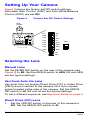
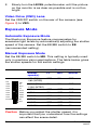
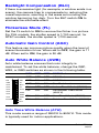
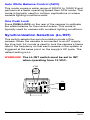
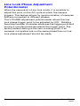
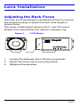
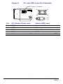
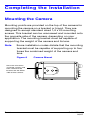
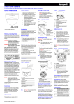
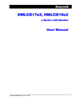
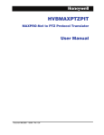
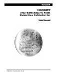
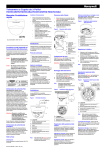
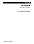
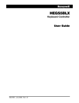
L-Series
Color Camera
NTSC
PAL
HCC334L
HCC334LX
HCC484L
HCC484LX
HCC335LX
HCC485LX
User Guide
Document G-113077-001 – 02/07 – Rev 3
Revisions
Issue
Date
Revisions
1.00
06/06
New document
1.01
08/06
Added 230V (HCC335LX, HCC485LX).
3
02/07
Updated document part no.; added
warning to p. iii.
Rev 3
ii
G-113077-001
02/07
Warnings
Installation and servicing should be performed only by
qualified and experienced personnel to conform to all local
codes and to maintain your warranty.
WARNING! 12 VDC/24 VAC models require the use
of CSA Certified/UL Listed Class 2
power adapters to ensure compliance
with electrical safety standards.
Where the MAINS plug or an appliance coupler is used as
the disconnect device, the disconnect device shall remain
readily operable.
WEEE (Waste Electrical and Electronic Equipment).
Correct disposal of this product (applicable in the
European Union and other European countries with
separate collection systems). This product should be
disposed of, at the end of its useful life, as per applicable
local laws, regulations, and procedures.
Explanation of Graphical
Symbols
THIS SYMBOL INDICATES THAT
DANGEROUS VOLTAGE
CONSTITUTING A RISK OF
ELECTRIC SHOCK IS PRESENT
WITHIN THE UNIT.
CAUTION
RISK OF ELECTRIC
SHOCK
DO NOT OPEN
CAUTION: TO REDUCE THE RISK OF ELECTRIC
SHOCK, DO NOT REMOVE THE COVER.
NO USER-SERVICEABLE PARTS INSIDE
REFER SERVICING TO QUALIFIED
SERVICE PERSONNEL
Rev 3
iii
THIS SYMBOL INDICATES THAT
IMPORTANT OPERATING AND
MAINTENANCE INSTRUCTIONS
ACCOMPANY THIS UNIT.
G-113077-001
02/07
FCC Compliance Statement
Information to the User: This equipment has been tested
and found to comply with the limits for a Class A digital
device. Pursuant to Part 15 of the FCC Rules, these limits
are designed to provide reasonable protection against
harmful interference when the equipment is operated in a
commercial environment. This equipment generates, uses,
and can radiate radio frequency energy and, if not installed
and used in accordance with the instruction manual, may
cause harmful interference to radio communications.
Operation of this equipment in a residential area is likely to
cause harmful interference in which case the user will be
required to correct the interference at his own expense.
Caution Changes or modifications not expressly
approved by the party responsible for
compliance could void the user’s authority to
operate the equipment.
Manufacturer’s Declaration of
Conformance
The manufacturer declares that the equipment supplied
with this guide is compliant with the essential protection
requirements of the EMC directive 89/336/EEC and the Low
Voltage Directive LVD 73/23 EEC, conforming to the
requirements of standards EN 55013 for emissions.
Rev 3
iv
G-113077-001
02/07
Contents
Introduction . . . . . . . . . . . . . . . . . . . . . . . . . . . . . . . 1
Features . . . . . . . . . . . . . . . . . . . . . . . . . . . . . . . . 1
Before You Begin . . . . . . . . . . . . . . . . . . . . . . . . . 2
Unpack Everything . . . . . . . . . . . . . . . . . . . . . . . . 2
Camera Settings . . . . . . . . . . . . . . . . . . . . . . . . . . . 3
Camera Functions . . . . . . . . . . . . . . . . . . . . . . . . 3
Setting Up Your Camera . . . . . . . . . . . . . . . . . . . 4
Selecting the Lens . . . . . . . . . . . . . . . . . . . . . . 4
Manual Lens . . . . . . . . . . . . . . . . . . . . . . . 4
Vari-focal Auto Iris Lens . . . . . . . . . . . . . . . 4
Direct Drive (DC) Lens . . . . . . . . . . . . . . . . 4
Video Drive (VSD) Lens . . . . . . . . . . . . . . . 5
Exposure Mode . . . . . . . . . . . . . . . . . . . . . . . . 5
Automatic Exposure Mode . . . . . . . . . . . . . 5
Manual Exposure Mode . . . . . . . . . . . . . . 5
Backlight Compensation (BLC). . . . . . . . . . . . 6
Flickerless Mode (FL) . . . . . . . . . . . . . . . . . . . . 6
Automatic Gain Control (AGC) . . . . . . . . . . . . 6
Auto White Balance (AWB) . . . . . . . . . . . . . . . 6
Auto Trace White Balance (ATW) . . . . . . . 6
Auto White Balance Control (AWC). . . . . . 7
One Push Lock . . . . . . . . . . . . . . . . . . . . . . 7
Synchronization Selection (LL/INT) . . . . . . . . . 7
Line Lock Phase Adjustment Potentiometer. . 8
Lens Installation . . . . . . . . . . . . . . . . . . . . . . . . . . . 9
Adjusting the Back Focus . . . . . . . . . . . . . . . . . . . 9
Completing the Installation . . . . . . . . . . . . . . . . . . 11
Mounting the Camera . . . . . . . . . . . . . . . . . . . . . 11
Connecting the Camera . . . . . . . . . . . . . . . . . . . 12
Warranty and Service . . . . . . . . . . . . . . . . . . . . . . 13
Specifications . . . . . . . . . . . . . . . . . . . . . . . . . . . . 13
Rev 3
G-113077-001
02/07
Introduction
The Honeywell L-Series Color cameras are ideally suited
for use in day-to-day surveillance applications. The LSeries cameras are designed for exceptional value and
performance for everyday use. Their off-the-shelf feature
set is designed for high picture quality in standard
applications and they require little to no adjustment after
installation.
Figure 1
Camera Overview
C/CS mount adapter:
C mount: turn
counterclockwise
CS mount: turn clockwise
Lens connector for
Auto Iris lens plug
Setscrew: loosen locking ring
with a Phillips screwdriver to
adjust mounting ring.
Features
•
•
•
•
•
1/3” CCD
C/CS adjustable lens mount adapter
Excellent signal-to-noise ratio of more than 50 dB
Minimum illumination:
• High Res — 0.4 lux (F1.2, 50 IRE, AGC ON)
• Standard Res — 0.2 lux (F1.2, 50 IRE, AGC ON)
2-way Auto Iris: Video Iris (VSD) or Direct Drive (DC)
Iris lens
Rev 3
1
G-113077-001
02/07
Before You Begin
Please read this guide carefully
before you install the L-Series Color
camera.
Keep this guide for future reference.
Unpack Everything
Check that the items received match those listed on the
order form and packing slip. The L-Series packing box
should include, in addition to this User Guide:
• One L-Series Color camera
• One Auto Iris lens plug
If any parts are missing or damaged, contact the dealer you
purchased the camera from or call Honeywell Customer
Service (see Contact Information on the back of this
manual).
Note
Rev 3
You will also require a Phillips screwdriver to
complete the installation.
2
G-113077-001
02/07
Camera Settings
Camera Functions
Figure 2
Camera Rear View
Mains 230V —Line Voltage
(HCC335LX, HCC485LX)
Low Voltage
(HCC334L/X, HCC484L/X)
9 7
8
4
10
10
7
V ID E O
PU SH
LOC K
IR IS
LEVEL
IR IS
LEVEL
1
L /L
L /L
EE
AES
5
OFF
D C 12V
A C 24V
V-P H
4
V ID E O
V-P H
PWR
6
8 9
GN D
ME
AI
B LC
FL
AG C
W B3
W B2
W B1
EE
AES
3
IN T
IN T
O FF
VSD
VSD
2
ME
AI
B LC
FL
AG C
WB3
WB2
WB1
PU SH
LOC K
PW R
~ 2 0 7 -2 5 3 VA C 5 0 H Z
DC
DC
6
Legend
#
Description
1
DIP switches for mode settings (see Figure 3)
2
Auto Iris Lens select switch, VSD for Video or DC for Direct
Drive
3
Sync select switch
4
Video output connector
5
Power input connector (24 VAC: 3 terminals)—Low Voltage
model only
6
Power LED indicator
7
DC Iris level adjustment, for use with DC Iris lens
8
V-Phase adjustment, for use with Line lock
9
Push Lock in White Balance (WB) mode
10
EEPROM data setting for factory use only
Rev 3
3
G-113077-001
02/07
Setting Up Your Camera
Figure 3 shows the factory set DIP switch settings.
Automatic Gain Control (AGC) and Auto White Balance
Control (AWC) are set ON.
Figure 3
Factory Set DIP Switch Settings
IRIS
LEVEL
EE
ME
AES
AI
OFF
BLC
OFF
FL
OFF
AGC
OFF
WB3
OFF
WB2
OFF
WB1
VIDEO
PUSH IRIS
LOCK LEVEL
V-PH
PWR
L/L
EE
AES
OFF
DC 12V
AC 24V
+
-
GND
ME
AI
BLC INT
FL
AGC VSD
WB3
WB2
WB1 DC
VSD
DC
= ON
= OFF
Selecting the Lens
Manual Lens
Set the EE/ME DIP switch on the rear of the camera (see
Figure 3) to EE. Set the AES/AI switch to AES. EE and AES
are the typical settings.
Vari-focal Auto Iris Lens
Vari-focal Auto Iris lenses (Direct Drive [DC] or Video Drive
[VSD]) are connected to the camera via a 4-pin square
socket located at the side of the camera. Set the AES/AI
DIP switch to AI. EE and AI are the typical settings.
To set a different exposure, see Exposure Mode on page 5.
Direct Drive (DC) Lens
1.
Set the VSD/DC switch on the rear of the camera to
DC. Set the AES/AI DIP switch to AI.
Rev 3
4
G-113077-001
02/07
2.
Slowly turn the LEVEL potentiometer until the picture
on the monitor is as clear as possible and is not too
bright.
Video Drive (VSD) Lens
Set the VSD/DC switch on the rear of the camera (see
Figure 3) to VSD.
Exposure Mode
Automatic Exposure Mode
The Electronic Exposure feature compensates for
excessive light levels by automatically adjusting the shutter
speed of the camera. Set the EE/ME switch to EE
(recommended setting).
Manual Exposure Mode
Set the EE/ME switch to ME. This setting is typically used
only in machine vision applications. The table below gives
the shutter speeds for the switch settings.
Switch Label
Shutter
speed(s)
FL
BLC
AES/AI
1/50 (PAL)
1/60 (NTSC)
OFF
ON
OFF
ON
OFF
EE
ME
AES
AI
OFF
BLC
OFF
FL
OFF
AGC
1/250
OFF
OFF
OFF
OFF
WB3
1/500
ON
OFF
OFF
OFF
WB2
1/1000
OFF
ON
ON
1/2000
ON
ON
ON
OFF
LEGEND
WB1
= ON
= OFF
ON
1/100 (PAL)
1/120 (NTSC)
1/4000
OFF
OFF
ON
1/10000
ON
OFF
ON
Caution Before you adjust the shutter speed, it is
important that you understand how the settings
can affect the scene detail.
Rev 3
5
G-113077-001
02/07
Backlight Compensation (BLC)
If there is excessive light (for example, a window exists in a
scene), the camera tries to compensate by reducing the
overall exposure, resulting in the areas surrounding the
window becoming too dark. Turn the BLC switch ON to
eliminate the silhouette effect.
Flickerless Mode (FL)
Set the FL switch to ON to remove the flicker in a picture.
For PAL models, the shutter speed is 1/100 second; for
NTSC models, the shutter speed is 1/120 second.
Automatic Gain Control (AGC)
This feature can improve picture quality when the level of
scene illumination is low. When set to OFF, the gain is 11
dB. When set to ON, the gain is 30 dB.
Auto White Balance (AWB)
Auto white balance ensures that color integrity is
maintained. To set the white balance, change the WB1,
WB2, or WB3 switches as shown in the following table.
WB1 WB2 WB3 AWB Mode
OFF
OFF
OFF
EE
ME
OFF
ON
OFF
AWC Mode
AES
AI
OFF
OFF
ON
ON
One Push Lock
BLC
OFF
FL
ON
OFF
OFF
Indoor Fixed Mode (3200°K)
OFF
AGC
ON
OFF
ON
OFF
WB3
Fluorescent Fixed Mode
(4200°K)
OFF
WB2
OFF
WB1
ON
ON
OFF
User Fixed Mode (4700°K)
ON
ON
ON
Outdoor Fixed Mode (6300°K)
LEGEND
= ON
ATW Mode
= OFF
Auto Trace White Balance (ATW)
This mode covers a range of 2800°K to 8000°K. This mode
is typically used for indoor applications.
Rev 3
6
G-113077-001
02/07
Auto White Balance Control (AWC)
This mode covers a wider range of 2000°K to 10000°K and
performs at a faster operating speed than ATW mode. This
mode is typically used for outdoor applications or where
variable lighting conditions exist.
One Push Lock
Press PUSH LOCK on the rear of the camera to calibrate
the white balance for the current scene. This mode is
typically used for scenes with constant lighting conditions.
Synchronization Selection (LL/INT)
This switch selects the synchronization mode of the
camera. When the camera is connected to an AC supply,
the Line lock (LL) mode is used to lock the camera’s frame
rate to the frequency so that each camera in the system is
triggered at the same point on the supply’s AC cycle. The
default setting is LL.
WARNING! The LL/INT switch must be set to INT
when operating from 12 VDC.
V-PH
VIDEO
PUSH
LOCK
IRIS
LEVEL
L/L
V-PH
PWR
L/L
EE
AES
OFF
DC 12V
AC 24V
Rev 3
+
-
GND
ME
AI
BLC INT
FL
AGC VSD
WB3
WB2
WB1 DC
7
INT
G-113077-001
02/07
Line Lock Phase Adjustment
Potentiometer
When the camera is in Line lock mode, it is possible to
adjust the point on the AC cycle at which the camera
triggers. This feature allows for synchronization of cameras
that are connected to different phases.
The V-PHASE adjustment potentiometer allows the line
lock phase trigger point to be adjusted by 270°. Rotating
the potentiometer clockwise advances the trigger point and
turning it counterclockwise retards the trigger point. The
factory default setting is the zero crossing point. If all
cameras in a system are on the same phase then no line
lock phase adjustment should be made.
Rev 3
8
G-113077-001
02/07
Lens Installation
Adjusting the Back Focus
The back focus adjustment is accessible at the front end of
the camera housing to adjust the back focal length or
picture focus.
The range of adjustment allows both C- and CS-mount
lenses to be used without the need for a spacer ring.
Figure 4
C
C/CS Mount
C
S
Setscrew
1.
2.
3.
Loosen the setscrew with a Phillips screwdriver.
Adjust the focus ring to focus the picture.
Retighten the setscrew.
Rev 3
9
G-113077-001
02/07
Figure 5
DC and VSD Lens Pin Definition
Auto Iris lens connector
2
1
4
3
1 3
2 4
Pin
DC (Direct Drive) lens
Video (VSD) lens
1
CTRL -
Power (+12V)
2
CTRL +
NC
3
DRV +
Video Signal
4
DRV -
GND
Set the select switch to DC
Set the select switch to VSD
Rev 3
10
G-113077-001
02/07
Completing the Installation
Mounting the Camera
Mounting points are provided on the top of the camera for
mounting the camera on a bracket or tripod. They are
designed to accept standard sized 1/4 x 20 mounting
screws. This bracket can be unscrewed and mounted onto
the opposite side of the camera, depending on your
application. The mounting bracket must be capable of
supporting the weight of the camera and its lens.
Note
Some installation codes dictate that the mounting
bracket must be capable of supporting up to four
times the combined weight of the camera and
lens.
Figure 6
Camera Mount
Unscrew 3 bracket
securing screws and
then resecure the
bracket on the other
side of the camera.
Rev 3
11
G-113077-001
02/07
Connecting the Camera
1.
2.
Connect the VIDEO connector on the rear of the
camera to the video-in connector on your monitor.
Connect the camera to a power supply appropriate for
your installation.
HCC334L/X, HCC484L/LX: 12 VDC or 24 VAC power
supply
HCC335LX, HCC485LX: 230V power supply
3.
Plug in the power supply. The power (PWR) LED
illuminates to show that the camera is receiving power.
If it does not illuminate, check the connections and the
power source.
Figure 7
Camera Connections
Low voltage model shown
(HCC334L/X, HCC484L/X)
Monitor
V ID E O
PUSH
LOC K
IR IS
LEVEL
V-P H
PW R
L /L
EE
AES
Power LED
OFF
D C 12V
AC 24V
Rev 3
GN D
12
ME
AI
B LC
FL
AG C
W B3
W B2
W B1
IN T
VSD
DC
G-113077-001
02/07
Warranty and Service
Subject to the terms and conditions listed on the Product warranty,
during the warranty period Honeywell will repair or replace, at its
sole option, free of charge, any defective product returned prepaid.
In the event you have a problem with any Honeywell product,
please call Customer Service at 1.800.796.CCTV (North America
only) for assistance or to request a Return Merchandise
Authorization (RMA) number. For Europe and the United
Kingdom, please contact your Honeywell dealer.
Be sure to have the model number, serial number, and the nature
of the problem available for the technical service representative.
Prior authorization must be obtained for all returns, exchanges, or
credits. Items shipped to Honeywell without a clearly identified
Return Merchandise Authorization (RMA) number may be
refused.
Specifications
Note
These specifications refer to all models, except
where otherwise noted.
Operational
Image Sensor:
Video
Standard:
Scanning
System:
Number of
Pixels (H x V):
Minimum
Illumination:
Horizontal
Resolution:
Rev 3
HCC334L
HCC334LX HCC484L
HCC335LX
NTSC
PAL
HCC484LX
HCC485LX
1/3” Super HAD CCD
NTSC
PAL
525 lines,
625 lines,
525 lines,
625 lines,
2:1 interlace 2:1 interlace 2:1 interlace 2:1 interlace
510 x 492
500 x 582
< 0.2 lux @ F1.2
(50 IRE, AGC ON)
330 TVL
330 TVL
13
768 x 494
752 x 582
< 0.4 lux @ F1.2
(50 IRE, AGC ON)
480 TVL
480 TVL
G-113077-001
02/07
HCC334L
HCC334LX HCC484L
HCC335LX
1 Vp-p @ 75 Ohms
Internal/Line lock
> 50 dB
On (30 dB)/Off (11 dB)
1/60 1/100,000
sec
1/50 1/100,000
sec
Video Output:
Sync System:
S/N Ratio:
Auto Gain
Control (AGC):
ALC:
Automatic
Electronic
Shutter (AES):
Lens Mount:
White Balance
(AWB):
EE/VSD/DC
1/60 1/100,000
sec
1/50 1/100,000
sec
C/CS mount (adjustable)
ATW/AWC/One Push Lock/Indoor/Outdoor/
Fluorescent/User
BLC:
On/Off
Gamma:
Electrical
Input Voltage:
HCC484LX
HCC485LX
0.45
HCC334L/LX, HCC484L/LX: 12 VDC/24 VAC
HCC335LX, HCC485LX: 230 VAC
Input Voltage
Range:
HCC334L/LX, HCC484L/LX: 11 - 16 VDC, 17 - 28 VAC
Power
Consumption:
HCC334L/LX, HCC484L/LX: 3.5 W
Mechanical
Dimension:
(W x H x D)
HCC335LX, HCC485LX: 230 VAC ± 10%
HCC335LX, HCC485LX: 4.2 W (max)
HCC334L/LX, HCC484L/LX: 2.68 x 2.2 x 4.72 in. (68 x
56 x 120 mm)
HCC335LX, HCC485LX: 2.68 x 2.2 x 5.51 in. (68 x 56 x
140 mm)
Weight:
HCC334L/LX, HCC484L/LX: 0.84 lb (.380 kg)
HCC335LX, HCC485LX: 0.90 lb (.410 kg)
Environmental
Temperature:
Operating: 14°F to 122°F (-10°C to +50°C)
Storage: -4°F to158°F (-20°C to +70°C)
Regulatory
Emissions:
Immunity:
Safety:
Rev 3
FCC, CE (EN55013)
CE (EN50130-4)
EU: 73/23/EEC LVD
14
G-113077-001
02/07
Honeywell Video Systems (Head office)
2700 Blankenbaker Pkwy, Suite 150
Louisville, KY 40299, USA
www.honeywellvideo.com
℡ +1.800.796.2288
Honeywell Security Australia Pty Ltd.
Unit 5, Riverside Centre
24-28 River Road West
Parramatta, NSW 2150, Australia
www.ademco.com.au
℡ +61.2.8837.9300
Honeywell Security Asia Pacific
33/F Tower A, City Center, 100 Zun Yi
Road
Shanghai 200051, China
www.security.honeywell.com/cn
℡ +86 21.2527.4568
Honeywell Video Systems
Northern Europe
Netwerk 121
1446 WV Purmerend, The Netherlands
www.SecurityHouse.nl
℡ +31.299.410.200
Honeywell Video Systems UK Ltd.
Aston Fields Road, Whitehouse Ind Est
Runcorn, Cheshire, WA7 3DL, UK
www.honeywellvideo.com
℡ +0844 8000 235
Honeywell Security South Africa
Unit 6 Galaxy Park, 17 Galaxy Avenue
Linbro Park, P.O. Box 59904
2100 Kengray, Johannesburg
South Africa
www.honeywell.co.za
℡ +27.11.574.2500
Honeywell Security Asia
Flat A, 16/F, CDW Building
388 Castle Peak Road
Tsuen Wan, N.T., Hong Kong
www.security.honeywell.com/hk
℡ +852.2405.2323
Honeywell Security Deutschland
Johannes-Mauthe-Straße 14
D-72458 Albstadt, Germany
www.honeywell.com/security/de
℡ +49.74 31.8 01.0
Honeywell Security France
Parc Gutenberg, 8, Voie La Cardon
91120, Palaiseau, France
www.honeywell.com/security/fr
℡ +33.01.64.53.80.40
Honeywell Security Poland
Chmielewskiego 22a, 70-028
Szczecin, Polska
www.ultrak.pl
℡ +48.91.485.40.60
Honeywell Security Italia SpA
Via Treviso 2 / 4
31020 San Vendemiano
Treviso, Italy
www.honeywell.com/security/it
℡ +39.04.38.36.51
Honeywell Security Czech Republic
Havránkova 33, Brno
Dolní Heršpice, 619 00
Czech Republic
www.olympo.cz
℡ +420.543.558.111
Honeywell Security España
Mijancas 1. 3a Planta
P.Ind. Las Mercedes
28022 Madrid, Spain
www.honeywell.com/security/es
℡ +34.902.667.800
Honeywell Security Slovakia Republic
Vajnorská 142, 83104 Bratislava
Slovakia
www.olympo.sk
℡ +421.2.444.54.660
www.honeywellvideo.com
+1.800.796.CCTV (North America only)
[email protected]
Document G-113077-001 02/07 Rev 3
© 2007 Honeywell International Inc. All rights reserved. No part of this publication
may be reproduced by any means without written permission from Honeywell Video
Systems. The information in this publication is believed to be accurate in all respects.
However, Honeywell Video Systems cannot assume responsibility for any
consequences resulting from the use thereof. The information contained herein is
subject to change without notice. Revisions or new editions to this publication may
be issued to incorporate such changes.