1
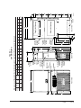
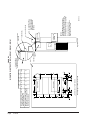
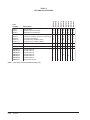
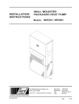
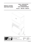
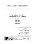
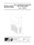
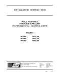
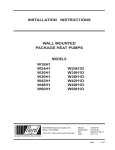
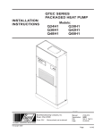
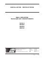
INSTALLATION
INSTRUCTIONS
WALL MOUNTED
PACKAGE AIR CONDITIONERS
MODELS
W38A1
W49A1
W61A1
Bard Manufacturing Company, Inc.
Bryan, Ohio 43506
Since 1914...Moving ahead just as planned.
Manual :
Supersedes:
File:
Date:
2100-530A
2100-530
Volume III Tab 16
12-15-11
Manual
Page
2100-530A
1 of 22
Contents
Getting Other Information and Publications
Wall Mount General Information
Wall Mount Model Nomenclature ............................
Shipping Damage ....................................................
General ................................................................
Duct Work ................................................................
Filters
................................................................
Fresh Air Intake .......................................................
Condensate Drain ....................................................
3
4
7
7
7
8
8
8
Installation Instructions
Wall Mounting Information ....................................... 9
Mounting the Unit .................................................... 9
Wiring – Main Power ............................................. 14
Wiring – Low Voltage Wiring ................................. 14
Figures
Figure 1
Figure 2
Figure 3
Figure 4
Figure 5
Figure 6
Figure 7
Figure 8
Figure 9
Figure 10
Figure 11
Unit Dimensions ...................................... 5
Fresh Air Damper Assembly ................... 8
Mounting Instructions ............................ 10
Electric Heat Clearance ......................... 11
Wall Mounting Instructions .................... 12
Wall Mounting Instructions .................... 12
Common Wall Mounting Installations .... 13
Fan Blade Setting ................................. 18
Control Disassembly ............................. 22
Winding Test ......................................... 22
Drip Loop .............................................. 22
Manual 2100-530A
Page
2 of 22
Start Up
R-410A / General ...................................................
Topping off System Charge ...................................
Safety Practices .....................................................
Important Installer Note .........................................
High Pressure Switch ............................................
Three Phase Scroll Compressor ............................
Phase Monitor .......................................................
Condenser Fan Operation .....................................
Service Hints .........................................................
Sequence of Operation ..........................................
Compressor Control Module ..................................
Adjustments ...........................................................
Pressure Service Ports ..........................................
15
15
15
16
16
16
16
16
16
17
17
17
17
Troubleshooting
Fan Blade Setting Dimensions .............................. 18
Removal of Fan Shroud ......................................... 18
Refrigerant Charge R-410A ................................... 18
Optional Accessories ............................................. 20
GE ECM™ Motors ......................................... 21 & 22
Tables
Table 1
Table 2
Table 3
Table 4
Table 5
Table 6
Table 7
Electric Heat Table .................................. 4
Electrical Specifications .......................... 6
Fan Blade Dimensions .......................... 18
Pressures - Cooling .............................. 18
Indoor Blower Performance .................. 19
Heater Pkgs.-Field Installed .................. 19
Optional Accessories ............................ 20
GETTING OTHER INFORMATION AND PUBLICATIONS
These publications can help you install the air
conditioner or heat pump. You can usually find these at
your local library or purchase them directly from the
publisher. Be sure to consult current edition of each
standard.
FOR MORE INFORMATION, CONTACT
THESE PUBLISHERS:
ACCA
Air Conditioning Contractors of America
1712 New Hampshire Ave. N.W.
Washington, DC 20009
Telephone: (202) 483-9370
Fax: (202) 234-4721
ANSI
American National Standards Institute
11 West Street, 13th Floor
New York, NY 10036
Telephone: (212) 642-4900
Fax: (212) 302-1286
National Electrical Code ...................... ANSI/NFPA 70
Standard for the Installation .............. ANSI/NFPA 90A
of Air Conditioning and Ventilating Systems
Standard for Warm Air ...................... ANSI/NFPA 90B
Heating and Air Conditioning Systems
Load Calculation for ............................ ACCA Manual J
Residential Winter and Summer Air Conditioning
Duct Design for Residential .............. ACCA Manual D
Winter and Summer Air Conditioning and Equipment
Selection
ASHRAE American Society of Heating, Refrigeration
and Air Conditioning Engineers, Inc.
1791 Tullie Circle, N.E.
Atlanta, GA 30329-2305
Telephone: (404) 636-8400
Fax: (404) 321-5478
NFPA
National Fire Protection Association
Batterymarch Park
P.O. Box 9101
Quincy, MA 02269-9901
Telephone: (800) 344-3555
Fax: (617) 984-7057
Manufactured under the following
U.S. Patent numbers:
5,485,878; 5,301,744
Manual 2100-530A
Page
3 of 22
WALL MOUNT GENERAL INFORMATION
AIR CONDITIONER WALL MOUNT MODEL NOMENCLATURE
W
38
A
1
A
REVISION
SERIES
CAPACITY |
38 - 3 Ton
49 - 4 Ton
61 - 5 Ton
10
X
X
X
X
COLOR OPTIONS
X - Beige
1 - White
4 - Buckeye Gray
5 - Desert Brown
8 - Dark Bronze
A - Aluminum
S - Stainless Steel
VENTILATION OPTIONS
X - Barometric Fresh Air Damper (Standard)
B - Blank-off Plate
M - Motorized Fresh Air Damper
V - Commercial Ventilator - Motorized with Exhaust
E - Economizer (Internal) - Fully Modulating with Exhaust
R - Energy Recovery Ventilator - Motorized with Exhaust
P - Commercial Ventilator - Power Return with Exhaust
X
CONTROL
MODULES
(See Spec.
Sheet S3412)
KW
VOLTS & PHASE
A - 230/208/60/1
B - 230/208/60/3
C - 460/60/3
AIR
CONDITIONER
X
COIL OPTIONS
X - No Coating
1 - Phenolic Coated Evaporator
2 - Phenolic Coated Condenser
3 - Phenolic Coated Evaporator
and Condenser
OUTLET OPTIONS
X - Front
FILTER OPTIONS
X - 1-Inch Fiberglass (MERV 2)
H - 2-Inch Pleated (MERV 8)
P - 2-Inch Pleated (MERV 6)
W - 1-Inch Washable
Note: For 0KW and circuit breakers (230/208 Volt) or rotary disconnect (460 Volt) applications, insert 0Z in the KW field of the model number.
TABLE 1
ELECTRIC HEAT TABLE
230-1
W38A1-C
W49A1-C
W61A1-C
W38A1-B
W49A1-B
W61A1-B
W38A1-A
W49A1-A
W61A1-A
Models
208-1
230-3
208-3
460-3
KW
A
B TU
A
B TU
A
B TU
A
B TU
A
B TU
5
20.8
17050
18.1
12800
---
---
---
---
---
---
6
---
---
---
---
14.4
20500
12.5
15360
7.2
20480
8
33.3
27280
28.8
20450
---
---
---
---
---
---
9
---
---
---
---
21.7
30600
18.7
23030
10.8
30700
10
41.6
34130
36.2
25600
---
---
---
---
---
---
15
62.5
51200
54.0
38400
36.2
51200
31.2
38400
17.3
47000
Manual 2100-530A
Page
4 of 22
Manual 2100-530A
Page
5 of 22
G
F
5.75
22.432
W61A1 42.075
RETURN
C
B
E
F
G
I
J
K
L
M
N
O
P
Q
R
S1
S2
T
Front View
High Voltage
Electrical
Entrance
Low Voltage
Electrical
Entrance
Ventilation
Air
Vent Option
Door
Filter Access
Panel
C. Breaker/
Disconnect
Access Panel
(Lockable)
Electric
Heat
Heater
Access
Panel
Built In
Rain Hood
4° Pitch
Side View
Cond.
Air
Inlet
D
K
Drain
J
C H
I
A
2.13
L
N
M
Optional
Electrical
Entrances
Top Rain
Flashing
Shipping
Location
Side Wall
Mounting
Brackets
(Built In)
P
Q
Back View
.44
MIS-2762
T
S2
S2
S1
S1
S1
R
Bottom Installation
Bracket
Return Air Opening
B
Supply Air Opening
O
E
94.875 9.88 29.88 15.88 29.88 43.88 19.10 41.66 30.00 42.68 36.94 44.69 42.43 3.37 43.00 33.88 10.00 1.44 16.00 21.00 1.88
84.875 9.88 29.88 15.88 29.88 43.88 19.10 31.66 30.00 32.68 26.94 34.69 32.43 3.37 43.00 23.88 10.00 1.44 16.00 16.00 1.88
Condenser
Air Outlet
W
22.432
WIDTH DEPTH HEIGHT SUPPLY
(W)
(D)
(H)
A
B
W38A1
42.075
W49A1
MODEL
Dimensions of Basic Unit for Architectural and I nstallation Requirements (Nominal)
FIGURE 1
UNIT DIMENSIONS
TABLE 2
ELECTRICAL SPECIFICATIONS
Single Circuit
Model
W38A1 - A0Z
A 05
A 08
A 10
A 15
W38A1 - B0Z
B 06
B 09
B 15
W38A1 - C0Z
C 06
C 09
C 15
W49A1 - A0Z 4
A 05 4
A 08 4
A 10
A 15
W49A1 - B0Z 4
B 06
B 09 4
B 15
W49A1 - C0Z 4
C 06
C 09 4
C 15
W61A1 - A0Z 4
A 05 4
A 08 4
A 10
A 15
W61A1- B0Z 4
B 06 4
B 09
B 15
W61A1 - C0Z 4
C 09 4
C 15
1
2
3
4
2
Rated
No. Field 3 Minimum 1 Maximum 2 Field
Circuit External Fuse Power
Ground
Volts
Power
Ampacity or Ckt. Brkr. Wire Size Wire
and Phase Circuits
230/208-1
1
1
230/208-3
460-3
230/208-1
1
1
230/208-3
460-3
230/208-1
1
1
230/208-3
460-3
1
1
1
or 2
or 2
1
1
1
1
1
1
1
1
1
1
1
or 2
or 2
1
1
1
1
1
1
1
1
1
1
1
or 2
or 2
1
1
1
1
1
1
1
32
35
50
61
87
26
27
36
54
14
15
19
28
39
39
51
61
87
30
30
37
55
15
15
19
28
48
48
51
61
87
36
36
37
55
18
19
28
45
45
50
70
90
35
35
40
60
15
15
20
30
50
50
60
70
90
45
45
45
60
20
20
20
30
60
60
60
70
90
50
50
50
60
25
25
30
8
8
8
6
3
8
8
8
6
14
14
12
10
8
8
6
6
3
8
8
8
6
12
12
12
10
8
8
6
6
3
8
8
8
6
10
10
10
10
10
10
8
8
10
10
10
10
14
14
12
10
10
10
10
8
8
10
10
10
10
12
12
12
10
10
10
8
8
8
10
10
10
10
10
10
10
Dual Circuit
3 Minimum
1 Maximum
2 Field
2 Ground
Circuit
External Fuse
Power
Wire Size
Ampacity
or Ckt. Brkr.
Wire Size
Ckt. A Ckt. B Ckt. A Ckt. B Ckt. A Ckt. B Ckt. A Ckt. B
35
35
26
52
45
45
30
60
8
8
10
6
10
10
10
10
39
39
26
52
50
50
30
60
8
8
10
6
10
10
10
10
48
48
26
52
60
60
30
60
6
6
10
6
10
10
10
10
Maximum size of the time delay fuse or HACR type circuit breaker for protection of field wiring conductors.
Based on 75°C copper wire. All wiring must conform to National Electrical Code and all local codes.
These “Minimum Circuit Ampacity” values are to be used for sizing the field power conductors. Refer to the National Electric
Code (latest revision), article 310 for power conductor sizing.
These models are available with dehumidification with hot gas reheat.
CAUTION: When more than one field power conductor circuit is run through one conduit, the conductors must be derated. Pay
special attention to note 8 of table 310 of the National Electrical Code regarding Ampacity Adjustment Factors when
more than 3 conductors are in a raceway.
IMPORTANT: While this electrical data is presented as a guide, it is important to electrically connect properly sized fuses & conductor wires in
accordance with the National Electrical Code & all local codes.
Manual 2100-530A
Page
6 of 22
SHIPPING DAMAGE
DUCT WORK
Upon receipt of equipment, the carton should be
checked for external signs of shipping damage. If
damage is found, the receiving party must contact the
last carrier immediately, preferably in writing,
requesting inspection by the carrier’s agent.
All duct work, supply and return, must be properly sized
for the design airflow requirement of the equipment.
Air Conditioning Contractors of America (ACCA) is an
excellent guide to proper sizing. All duct work or
portions thereof not in the conditioned space should be
properly insulated in order to both conserve energy and
prevent condensation or moisture damage.
GENERAL
The equipment covered in this manual is to be installed
by trained, experienced service and installation
technicians.
The refrigerant system is completely assembled and
charged. All internal wiring is complete.
The unit is designed for use with or without duct work.
Flanges are provided for attaching the supply and return
ducts.
These instructions explain the recommended method to
install the air cooled self-contained unit and the
electrical wiring connections to the unit.
These instructions and any instructions packaged with
any separate equipment required to make up the entire
air conditioning system should be carefully read before
beginning the installation. Note particularly “Starting
Procedure” and any tags and/or labels attached to the
equipment.
While these instructions are intended as a general
recommended guide, they do not supersede any national
and/or local codes in any way. Authorities having
jurisdiction should be consulted before the installation
is made. See Page 3 for information on codes and
standards.
Size of unit for a proposed installation should be based
on heat loss calculation made according to methods of
Air Conditioning Contractors of America (ACCA). The
air duct should be installed in accordance with the
Standards of the National Fire Protection Association
for the Installation of Air Conditioning and Ventilating
Systems of Other Than Residence Type, NFPA No.
90A, and Residence Type Warm Air Heating and Air
Conditioning Systems, NFPA No. 90B. Where local
regulations are at a variance with instructions, installer
should adhere to local codes.
ESP maximum static pressure is 0.50 for duct design.
Design the duct work according to methods given by the
Air Conditioning Contractors of America (ACCA).
When duct runs through unheated spaces, it should be
insulated with a minimum of one inch of insulation.
Use insulation with a vapor barrier on the outside of the
insulation. Flexible joints should be used to connect the
duct work to the equipment in order to keep the noise
transmission to a minimum.
A 1/4 inch clearance to combustible material for the
first three feet of duct attached to the outlet air frame is
required. See Wall Mounting Instructions and Figures 3
and 4 for further details.
Ducts through the walls must be insulated and all joints
taped or sealed to prevent air or moisture entering the
wall cavity.
Some installations may not require any return air duct.
A metallic return air grille is required with installations
not requiring a return air duct. The spacing between
louvers on the grille shall not be larger than 5/8 inch.
Any grille that meets with 5/8 inch louver criteria may
be used. It is recommended that Bard Return Air Grille
Kit RG2 through RG5, or RFG2 through RFG5 be
installed when no return duct is used. Contact
distributor or factory for ordering information. If using
a return air filter grille, filters must be of sufficient size
to allow a maximum velocity of 400 fpm.
NOTE: If no return air duct is used, applicable
installation codes may limit this cabinet to
installation only in a single story structure.
Manual 2100-530A
Page
7 of 22
FILTERS
CONDENSATE DRAIN
A 1-inch throwaway filter is supplied with each unit.
The filter slides into position making it easy to service.
This filter can be serviced from the outside by removing
the service door. A 1-inch washable filter and 2-inch
pleated filter are also available as optional accessories.
The internal filter brackets are adjustable to
accommodate the 2-inch filter by loosening two (2)
screws on each bracket assembly and sliding the
brackets apart to the required width and retightening the
four (4) screws.
A plastic drain hose extends from the drain pan at the
top of the unit down to the unit base. There are
openings in the unit base for the drain hose to pass
through. In the event the drain hose is connected to a
drain system of some type, it must be an open or vented
type system to assure proper drainage.
FRESH AIR INTAKE
All units are built with fresh air inlet slots punched in
the service door.
If the unit is equipped with a fresh air damper assembly,
the assembly is shipped already attached to the unit.
The damper blade is locked in the closed position. To
allow the damper to operate, the maximum and
minimum blade position stops must be installed. See
Figure 2.
All capacity, efficiency and cost of operation
information as required for Department of Energy
“Energyguide” Fact Sheets is based upon the fresh air
blank-off plate in place and is recommended for
maximum energy efficiency.
The blank-off plate is available upon request from the
factory and is installed in place of the fresh air damper
shipped with each unit.
FIGURE 2
FRESH AIR DAMPER
Manual 2100-530A
Page
8 of 22
INSTALLATION INSTRUCTIONS
WALL MOUNTING INFORMATION
1. Two holes for the supply and return air openings
must be cut through the wall as shown in Figure 3.
2. On wood frame walls, the wall construction must be
strong and rigid enough to carry the weight of the
unit without transmitting any unit vibration.
3. Concrete block walls must be thoroughly inspected
to insure that they are capable of carrying the weight
of the installed unit.
WARNING
Failure to provide the 1/4 inch clearance
between the supply duct and a combustible
surface for the first 3 feet of duct can result in
fire causing damage, injury or death.
4. Mount bottom mounting bracket.
MOUNTING THE UNIT
1. These units are secured by wall mounting brackets
which secure the unit to the outside wall surface at
both sides. A bottom mounting bracket, attached to
skid for shipping, is provided for ease of installation,
but is not required.
2. The unit itself is suitable for 0 inch clearance, but
the supply air duct flange and the first 3 feet of
supply air duct require a minimum of 1/4 inch
clearance to combustible material. If a combustible
wall, use a minimum of 30½" x 10½" dimensions for
sizing. However, it is generally recommended that a
1-inch clearance is used for ease of installation and
maintaining the required clearance to combustible
material. The supply air opening would then be
32" x 12". See Figures 3 and 4 for details.
3. Locate and mark lag bolt locations and bottom
mounting bracket location. See Figure 3.
5. Hook top rain flashing, attached to front - right of
supply flange for shipping, under back bend of top.
Top rain flashing is shipped secured to the right side
of the back.
6. Position unit in opening and secure with 5/16 lag
bolts; use 7/8 inch diameter flat washers on the lag
bolts.
7. Secure rain flashing to wall and caulk across entire
length of top. See Figure 3.
8. For additional mounting rigidity, the return air and
supply air frames or collars can be drilled and
screwed or welded to the structural wall itself
(depending upon wall construction). Be sure to
observe required clearance if combustible wall.
9. On side-by-side installations, maintain a minimum
of 20 inches clearance on right side to allow access
to control panel and heat strips, and to allow proper
airflow to the outdoor coil. Additional clearance
may be required to meet local or national codes.
Manual 2100-530A
Page
9 of 22
Manual 2100-530A
Page
10 of 22
7
18"
16"
16"
16"
16"
16"
1
1
4"
Typ.
1
1
62"
C
5 1/2
6 1/4
C
38"
Dimension is 21" on 95" tall Units.
4"
Typ.
1"
3"
30"
Return Opening
Supply Opening
A
12
10 1/2
B
Wall Opening and Hole Location View
1
1
62"
1
62"
C
32
REQUIRED DIMENSIONS TO MAINTAIN
RECOMMENDED 1" CLEARANCE FROM
COMBUSTIBLE MATERIALS
D
30 1/2
REQUIRED DIMENSIONS TO MAINTAIN
1/4" MIN. CLEARANCE FROM
COMBUSTIBLE MATERIALS
A
2
E
29
29 3/4
7
8"
28"
1
16"
E
B
1 1/4
D
TOP
HEATER ACCESS
PANEL
WALL
SEAL WITH BEAD
OF CAULKING ALONG
ENTIRE LENGTH OF
TOP.
Right Side View
MIS-416 D
W**A UNIT SHOWN, W**L UNIT
CONTROLS AND HEATER ACCESS
IS ON OPPOSITE (LEFT) SIDE.
IT IS RECOMMENDED THAT A BEAD OF
SILICONE CAULKING BE PLACED BEHIND
THE SIDE MOUNTING FLANGES AND UNDER
TOP FLASHING AT TIME OF INSTALLATION.
NOTES:
RETURN AIR
OPENING
SUPPLY AIR
DUCT
1/4" CLEARANCE ON ALL
FOUR SIDES OF SUPPLY
AIR DUCT IS REQUIRED
FROM COMBUSTABLE
MATERIALS
WALL STRUCTURE
FOAM AIR SEAL
RAIN FLASHING
SUPPLIED
FIGURE 3
MOUNTING INSTRUCTIONS for W38A1, W49A1, W61A1
FIGURE 4
ELECTRIC HEAT CLEARANCE
BELOW
SIDE SECTION VIEW OF SUPPLY AIR DUCT FOR
WALL MOUNTED UNIT SHOWING 1/4 INCH
CLEARANCE TO COMBUSTIBLE SURFACES.
WARNING
A minimum of 1/4 inch clearance must be maintained between
the supply air duct and combustible materials. This is required
for the first 3 feet of ducting.
It is important to insure that the 1/4 inch minimum spacing is
maintained at all points.
Failure to do this could result in overheating the combustible
material and may result in a fire causing damage, injury or death.
Manual 2100-530A
Page
11 of 22
FIGURE 5
WALL MOUNTING INSTRUCTIONS
SEE FIGURE 3 – MOUNTING INSTRUCTIONS
FIGURE 6
WALL MOUNTING INSTRUCTIONS
SEE UNIT DIMENSIONS, FIGURE
1, FOR ACTUAL DIMENSIONS
Manual 2100-530A
Page
12 of 22
FIGURE 7
COMMON WALL MOUNTING INSTALLATIONS
Manual 2100-530A
Page
13 of 22
WIRING – MAIN POWER
WIRING – LOW VOLTAGE WIRING
Refer to the unit rating plate for wire sizing information
and maximum fuse or “HACR” type circuit breaker
size. Each outdoor unit is marked with a “Minimum
Circuit Ampacity”. This means that the field wiring
used must be sized to carry that amount of current.
Depending on the installed KW of electric heat, there
may be two field power circuits required. If this is the
case, the unit serial plate will so indicate. All models
are suitable only for connection with copper wire. Each
unit and/or wiring diagram will be marked “Use Copper
Conductors Only”. These instructions must be adhered
to. Refer to the National Electrical Code (NEC) for
complete current carrying capacity data on the various
insulation grades of wiring material. All wiring must
conform to NEC and all local codes.
230/208V, 1 phase and 3 phase equipment dual primary
voltage transformers. All equipment leaves the factory
wired on 240V tap. For 208V operation, reconnect from
240V to 208V tap. The acceptable operating voltage
range for the 240 and 208V taps are:
The electrical data lists fuse and wire sizes (75° C
copper) for all models including the most commonly
used heater sizes. Also shown are the number of field
power circuits required for the various models with
heaters.
The unit rating plate lists a “Maximum Time Delay
Relay Fuse” or “HACR” type circuit breaker that is to
be used with the equipment. The correct size must be
used for proper circuit protection and also to assure that
there will be no nuisance tripping due to the momentary
high starting current of the compressor motor.
The disconnect access door on this unit may be locked
to prevent unauthorized access to the disconnect. To
convert for the locking capability, bend the tab located
in the bottom left-hand corner of the disconnect opening
under the disconnect access panel straight out. This tab
will now line up with the slot in the door. When shut, a
padlock may be placed through the hole in the tab
preventing entry.
See “Start Up” section for important information on
three phase scroll compressor start ups.
See Table 2 for Electrical Specifications.
Manual 2100-530A
Page
14 of 22
TAP
240
208
RANGE
253 – 216
220 – 187
NOTE: The voltage should be measured at the field power
connection point in the unit and while the unit is
operating at full load (maximum amperage
operating condition).
For wiring size and connections, refer to Wiring Manual
2100-507.
START UP
THESE UNITS REQUIRE R-410A
REFRIGERANT AND POLYOL
ESTER OIL.
REMEMBER: When adding R-410A refrigerant, it
must come out of the charging cylinder/tank as a liquid
to avoid any fractionation, and to insure optimal system
performance. Refer to instructions for the cylinder that
is being utilized for proper method of liquid extraction.
GENERAL:
1. Use separate service equipment to avoid cross
contamination of oil and refrigerants.
2. Use recovery equipment rated for R-410A
refrigerant.
3. Use manifold gauges rated for R-410A (800 psi/250
psi low).
WARNING
Failure to conform to these practices
could lead to damage, injury or death.
4. R-410A is a binary blend of HFC-32 and HFC-125.
5. R-410A is nearly azeotropic - similar to R-22 and
R-12. Although nearly azeotropic, charge with
liquid refrigerant.
6. R-410A operates at 40-70% higher pressure than
R-22, and systems designed for R-22 cannot
withstand this higher pressure.
7. R-410A has an ozone depletion potential of zero,
but must be reclaimed due to its global warming
potential.
8. R-410A compressors use polyolester oil.
9. Polyol Ester oil is hygroscopic; it will rapidly absorb
moisture and strongly hold this moisture in the oil.
10. A liquid line dryer must be used - even a deep
vacuum will not separate moisture from the oil.
11. Limit atmospheric exposure to 15 minutes.
12. If compressor removal is necessary, always plug
compressor immediately after removal. Purge with
small amount of nitrogen when inserting plugs.
TOPPING OFF SYSTEM CHARGE
If a leak has occurred in the system, Bard Manufacturing
recommends reclaiming, evacuating (see criteria above),
and charging to the nameplate charge. If done correctly,
topping off the system charge can be done without
problems.
With R-410A, there are no significant changes in the
refrigerant composition during multiple leaks and
recharges. R-410A refrigerant is close to being an
azeotropic blend (it behaves like a pure compound or
single component refrigerant). The remaining
refrigerant charge, in the system, may be used after
leaks have occurred and then “top-off” the charge by
utilizing the pressure charts on the inner control panel
cover as a guideline.
SAFETY PRACTICES:
1. Never mix R-410A with other refrigerants.
2. Use gloves and safety glasses, Polyol Ester oils can
be irritating to the skin, and liquid refrigerant will
freeze the skin.
3. Never use air and R-410A to leak check; the
mixture may become flammable.
4. Do not inhale R-410A – the vapor attacks the
nervous system, creating dizziness, loss of
coordination and slurred speech. Cardiac
irregularities, unconsciousness and ultimate death
can result from breathing this concentration.
5. Do not burn R-410A. This decomposition
produces hazardous vapors. Evacuate the area if
exposed.
6. Use only cylinders rated DOT4BA/4BW 400.
7. Never fill cylinders over 80% of total capacity.
8. Store cylinders in a cool area, out of direct
sunlight.
9. Never heat cylinders above 125°F.
10. Never trap liquid R-410A in manifold sets, gauge
lines or cylinders. R-410A expands significantly
at warmer temperatures. Once a cylinder or line is
full of liquid, any further rise in temperature will
cause it to burst.
Manual 2100-530A
Page
15 of 22
START UP
IMPORTANT INSTALLER NOTE
PHASE MONITOR
For improved start up performance wash the indoor coil
with a dish washing detergent.
All units with three phase scroll compressors are
equipped with a 3 phase line monitor to prevent
compressor damage due to phase reversal.
HIGH PRESSURE SWITCH
The W38A1, W49A1 and W61A1 models are supplied
with a remote reset high pressure switch. If tripped, this
pressure switch may be reset by turning the thermostat
off then back on again.
THREE PHASE SCROLL COMPRESSOR
START UP INFORMATION
Scroll compressors, like several other types of
compressors, will only compress in one rotational
direction. Direction of rotation is not an issue with
single phase compressors since they will always start
and run in the proper direction.
However, three phase compressors will rotate in either
direction depending upon phasing of the power. Since
there is a 50-50 chance of connecting power in such a
way as to cause rotation in the reverse direction,
verification of proper rotation must be made.
Verification of proper rotation direction is made by
observing that suction pressure drops and discharge
pressure rises when the compressor is energized.
Reverse rotation also results in an elevated sound level
over that with correct rotation, as well as, substantially
reduced current draw compared to tabulated values.
Verification of proper rotation must be made at the
time the equipment is put into service. If improper
rotation is corrected at this time, there will be no
negative impact on the durability of the compressor.
However, reverse operation for over one hour may have
a negative impact on the bearing due to oil pump out.
NOTE: If compressor is allowed to run in reverse rotation
for several minutes, the compressor’s internal
protector will trip.
All three phase ZR compressors are wired identically
internally. As a result, once the correct phasing is
determined for a specific system or installation,
connecting properly phased power leads to the same
Fusite terminal should maintain proper rotation
direction.
The direction of rotation of the compressor may be
changed by reversing any two line connections to the
unit.
Manual 2100-530A
Page
16 of 22
The phase monitor in this unit is equipped with two
LEDs. If the Y signal is present at the phase monitor
and phases are correct the green LED will light.
If phases are reversed, the red fault LED will be lit and
compressor operation is inhibited.
If a fault condition occurs, reverse two of the supply
leads to the unit. Do not reverse any of the unit factory
wires as damage may occur.
CONDENSER FAN OPERATION
The condenser fan motor on 230/208 volt, one and three
phase, 60 HZ units is a two-speed motor that comes
factory wired on high speed for peak performance. If
ambient conditions permit, it can be reconnected to low
speed (red wire) for lower sound level. See wiring
diagram.
50 HZ models must have fan wired on low speed.
These models are factory wired on low speed.
SERVICE HINTS
1. Caution owner/operator to maintain clean air filters
at all times. Also, not to needlessly close off supply
and return air registers. This reduces airflow
through the system, which shortens equipment
service life as well as increasing operating costs.
2. Check all power fuses or circuit breakers to be sure
they are the correct rating.
3. Periodic cleaning of the outdoor coil to permit full
and unrestricted airflow circulation is essential.
SEQUENCE OF OPERATION
Alarm Relay Output
COOLING – Circuit R-Y makes at thermostat pulling
in compressor contactor, starting the compressor and
outdoor motor. The G (indoor motor) circuit is
automatically completed on any call for cooling
operation or can be energized by manual fan switch on
subbase for constant air circulation. On a call for
heating, circuit R-W1 make at the thermostat pulling in
heat contact for the strip heat and blower operation. On
a call for second stage heat, R-W2 makes bringing on
second heat contactor, if so equipped.
Alarm terminal is output connection for applications
where alarm relay is employed. This terminal is
powered whenever the compressor is locked out due to
HPC or LPC sequences as described.
COMPRESSOR CONTROL MODULE
The compressor control module is standard on all
models covered by this manual. The compressor control
module is an anti-short cycle/lockout timer with high
and low pressure switch monitoring and alarm relay
output.
Adjustable Delay On Make And Break Timer
On initial power up or anytime power is interrupted to
the unit, the delay on make period begins, which will be
2 minutes plus 10% of the delay on break setting. When
the delay on make is complete and the high pressure
switch and low pressure switch is closed, the compressor
contactor is energized. Upon shutdown, the delay on
break timer starts and prevents restart until the delay on
break and delay on make periods have expired.
During routine operation of the unit with no power
interruptions, the compressor will operate on demand
with no delay.
High Pressure Switch and Lockout Sequence
If the high pressure switch opens, the compressor
contactor will de-energize immediately. The lockout
timer will go into a soft lockout and stay in soft lockout
until the high pressure switch closes and the delay on
break time has expired. If the high pressure switch
opens again in this same operating cycle, the unit will go
into manual lockout condition and the alarm relay circuit
will energize. Recycling the wall thermostat resets the
manual lockout.
Low Pressure Switch, Bypass, and Lockout
Sequence
NOTE: Both high and low pressure switch controls are
inherently automatic reset devices. The high
pressure switch and low pressure switch cut out
and cut in settings are fixed by specific air
conditioner unit model. The lockout features,
both soft and manual, are a function of the
Compressor Control Module.
ADJUSTMENTS
Adjustable Delay on Make and Delay on Break
Timer
The potentiometer is used to select Delay on Break time
from 30 seconds to 5 minutes. Delay on Make (DOM)
timing on power-up and after power interruptions is
equal to 2 minutes plus 10% of Delay on Break (DOB)
setting:
0.5 minute
1.0 minute
2.0 minute
3.0 minute
4.0 minute
5.0 minute
(30 seconds)
(60 seconds)
(120 seconds)
(180 seconds)
(240 seconds)
(300 seconds)
DOB = 123
DOB = 126
DOB = 132
DOB = 138
DOB = 144
DOB = 150
second DOM
second DOM
second DOM
second DOM
second DOM
second DOM
During routine operation of the unit with no power
interruptions the compressor will operate on demand
with no delay.
Typical Settings for Dual Unit Installation:
Unit 1: DOB set at 2 minutes, and DOM is 132 seconds
Unit 2: DOB set at 4 minutes, and DOM is 144 seconds
PRESSURE SERVICE PORTS
High and low pressure service ports are installed on all
units so that the system operating pressures can be
observed. A pressure table can be found later in the
manual covering all models. It is imperative to match
the correct pressure table to the unit by model number.
If the low pressure switch opens for more than 120
seconds, the compressor contactor will de-energize and
go into a soft lockout. Regardless the state of the low
pressure switch, the contactor will reenergize after the
delay on make time delay has expired. If the low
pressure switch remains open, or opens again for longer
than 120 seconds, the unit will go into manual lockout
condition and the alarm relay circuit will energize.
Recycling the wall thermostat resets the manual lockout.
Manual 2100-530A
Page
17 of 22
TROUBLESHOOTING
REMOVAL OF FAN SHROUD
FAN BLADE SETTING DIMENSIONS
Shown in Figure 8 is the correct fan blade setting
dimension for proper air delivery across the outdoor coil.
Any service work requiring removal or adjustment in
the fan and/or motor area will require that the
dimensions below be checked and blade adjusted in or
out on the motor shaft accordingly.
FIGURE 8
FAN BLADE SETTING
1. Disconnect all power to the unit.
2. Remove the screws holding both grilles, one on each
side of unit, and remove grilles.
3. Remove screws holding fan shroud to condenser and
bottom. Nine (9) screws.
4. Unwire condenser fan motor.
5. Slide complete motor, fan blade, and shroud
assembly out the left side of the unit.
6. Service motor/fan as needed.
7. Reverse steps to reinstall.
R-410A
REFRIGERANT CHARGE
TABLE 3
FAN BLADE DIMENSION
Model
Dimension
A
W38A1
W49A1
W61A1
1.75"
MIS-1724
This unit was charged at the factory with the quantity of
refrigerant listed on the serial plate. AHRI capacity and
efficiency ratings were determined by testing with this
refrigerant charge quantity.
The following pressure tables show nominal pressures
for the units. Since many installation specific situations
can affect the pressure readings, this information should
only be used by certified technicians as a guide for
evaluating proper system performance. They shall not
be used to adjust charge. If charge is in doubt, reclaim,
evacuate and recharge the unit to the serial plate charge.
TABLE 4
COOLING PRESSURE — (ALL TEMPERATURES IN DEGREES F)
R E TU R N
AIR
MODEL
TEMP. PRESSURE
W38A1
W49A1
W61A1
AIR TEMPERATURE ENTERING OUTDOOR COIL
75
80
85
90
95
100
105
110
115
75 D B
62 WB
Low S i de
High Side
118
319
121
338
122
360
124
383
126
408
128
434
130
461
131
489
133
520
80 D B
67 WB
Low S i de
High Side
126
327
129
347
131
369
133
393
134
418
137
445
139
473
140
502
142
533
85 D B
72 WB
Low S i de
High Side
130
338
134
359
136
382
138
407
140
433
142
461
144
490
145
520
147
552
75 D B
62 WB
Low S i de
High Side
125
335
126
358
126
381
127
405
128
430
130
455
133
482
136
508
140
536
80 D B
67 WB
Low S i de
High Side
134
344
135
367
135
391
136
415
140
439
140
467
142
494
145
521
150
550
85 D B
72 WB
Low S i de
High Side
139
356
140
380
140
405
141
430
142
456
144
483
147
511
150
539
155
569
75 D B
62 WB
Low S i de
High Side
115
345
116
363
118
382
119
403
121
426
122
450
124
476
126
504
128
533
80 D B
67 WB
Low S i de
High Side
123
354
124
372
126
392
127
413
131
415
131
462
133
488
135
517
137
547
85 D B
72 WB
Low S i de
High Side
127
366
128
385
130
406
131
427
134
452
136
478
138
505
140
535
142
566
Low side pressure ± 4 psig
High side pressure ± 10 psig
Tables are based upon rated CFM (airflow) across the evaporator coil. If there is any doubt as to correct operating charge being
in the system, the charge should be removed, system evacuated and recharged to serial plate instructions.
Manual 2100-530A
Page
18 of 22
TABLE 5
INDOOR BLOWER PERFORMANCE CFM (0.00" – 0.50" H2O) 1
NOTE:
Model
Rated
ESP
1
Max
ESP
2
Blow er
Only
3
Cooling
4
Electric
H eat
W38A
.15
.50
1100
1100
1100
W49A
.20
.50
1400
1400
1400
W61A
.20
.50
1450
1450
1450
These units are equipped with a variable speed (ECM) indoor motor that automatically adjusts itself to maintain approximately the
same rate of indoor airflow in both heating & cooling, dry & wet coil conditions and at both 230/208 or 460 volts.
1 Maximum ESP (inches WC) shown is with 2" thick disposable filter.
2 Blower only CFM is the total air being circulated during continuous fan mode.
3 CFM output on Cooling or Electric Heat.
TABLE 6
HEATER PACKAGES - FIELD INSTALLED
• Designed for adding Electric Heat to 0 KW Units
• Circuit Breaker Standard on 230/208V Models
Air Conditioner
Models
W38A1
W49A1
W61A1
-A00 Models
230/208-1
Heater Model #
EHS03A-A05
EHS03A-A08
EHS03A-A10
EHS03A-A15
EHS04A-A05
EHS04A-A08
EHS03A-A10
EHS04A-A15
EHS05A-A05
EHS04A-A08
EHS05A-A10
EHS05A-A15
KW
5
8
10
15
5
8
10
15
5
8
10
15
• ETL US & Canada Listed
• Rotary Disconnect Standard on 460V Models
-B00 Models
230/208-3
Heater Model #
KW
-C00 Models
460-3
Heater Model #
KW
EHS03A-B06
EHS03A-B09
EHS03A-B15
6
9
15
EHS03A-C06
EHS03A-C09
EHS03A-C15
6
9
15
EHS03A-B06
EHS04A-B09
EHS04A-B15
6
9
15
EHS03A-C06
EHS04A-C09
EHS04A-C15
6
9
15
EHS04A-B09
EHS04A-B15
9
15
EHS04A-C09
EHS04A-C15
9
15
Manual 2100-530A
Page
19 of 22
NOTE:
Part
Number
Description
W38A1-A
W38A1-B
W38A1-C
W49A1-A
W49A1-B
W49A1-C
W61A1-A
W61A1-B
W61A1-C
TABLE 7
OPTIONAL ACCESSORIES
BOP-5
BFAD-5
MFAD-5
Blank Off Plate
Barometric Fresh Air Damper
Motorized Fresh Air Damper
X
X
X
X
X
X
X
X
X
X
X
X
X
X
X
X
X
X
X
X
X
X
X
X
X
X
X
CRVS-5
CRVS-5
EIFM-5C
ERVF-A3-*
ERVF-C3-*
Commercial Ventilator w/Exhaust - Spring Return
Commercial Ventilator w/Exhaust - Power Return
Economizer with Exhaust
Energy Recovery Ventilator (230V)
Energy Recovery Ventilator (460V)
X
X
X
X
X
X
X
X
X
X
X
X
X
X
X
X
X
X
X
X
X
X
X
X
X
X
X
X
X
X
X
X
X
CMA-28
Low Ambient Control (LAC)
X
X
X
X
X
X
X
X
X
CMA-14
Outdoor Thermostat
X
X
X
X
X
X
X
X
X
WMCB-07A
WMCB-05B
WMCB-08A
WMCB-07B
WMCB-09A
WMCB-08B
WMRD-01C
Circuit Breaker Kit
Circuit Breaker Kit
Circuit Breaker Kit
Circuit Breaker Kit
Circuit Breaker Kit
Circuit Breaker Kit
Rotary Disconnect Kit
X
Color option must be specified to match units.
Manual 2100-530A
Page
20 of 22
X
X
X
X
X
X
X
X
X
X
X
TROUBLESHOOTING GE ECM™ MOTORS
CAUTION:
Symptom
Cause/Procedure
Disconnect power from unit before removing or replacing
connectors, or servicing motor. To avoid electric shock
from the motor’s capacitors, disconnect power and wait at
least 5 minutes before opening motor.
• Noisy blower or cabinet
• Check for loose blower housing, panels, etc.
• High static creating high blower speed?
- Check for air whistling through seams in
ducts, cabinets or panels
- Check for cabinet/duct deformation
Symptom
Cause/Procedure
Motor rocks slightly
when starting
• This is normal start-up for ECM
• “Hunts” or “puffs” at
high CFM (speed)
• Does removing panel or filter reduce
“puffing”?
- Reduce restriction
- Reduce max. airflow
Motor won’t start
• No movement
• Check blower turns by hand
• Check power at motor
• Check low voltage (24 Vac R to C) at motor
• Check low voltage connections
(G, Y, W, R, C) at motor
• Check for unseated pins in connectors on
motor harness
• Test with a temporary jumper between R - G
• Check motor for tight shaft
• Perform motor/control replacement check
• Perform Moisture Check
• Motor rocks,
but won’t start
Motor oscillates up
load & down while being
tested off of blower
Motor starts, but
runs erratically
• Varies up and down
or intermittent
• Check for loose or compliant motor mount
• Make sure blower wheel is tight on shaft
• Perform motor/control replacement check
• It is normal for motor to oscillate with no
on shaft
• Check line voltage for variation or “sag”
• Check low voltage connections
(G, Y, W, R, C) at motor, unseated pins in
motor harness connectors
• Check “Bk” for erratic CFM command (in
variable-speed applications)
• Check out system controls, Thermostat
• Perform Moisture Check
Evidence of Moisture
• Motor failure or
Check
malfunction has occurred
and moisture is present
• Evidence of moisture
present inside air mover
• Perform Moisture Check
Do
Don’t
• Check out motor, controls,
wiring and connections
thoroughly before replacing
motor
• Orient connectors down so
water can’t get in
- Install “drip loops”
• Use authorized motor and
model #’s for replacement
• Keep static pressure to a
minimum:
- Recommend high
efficiency, low static filters
- Recommend keeping filters
clean.
- Design ductwork for min.
static, max. comfort
- Look for and recommend
ductwork improvement,
where necessary
• Automatically assume the motor is bad.
• “Hunts” or “puffs” at
high CFM (speed)
• Does removing panel or filter reduce
“puffing”?
- Reduce restriction
- Reduce max airflow
• Size the equipment wisely
• Stays at low CFM
despite system call
for cool or heat CFM
• Check low voltage (Thermostat) wires and
connections
• Verify fan is not in delay mode; wait until
delay complete
• “R” missing/not connected at motor
• Perform motor/control replacement check
Moisture Check
• Stays at high CFM
• “R” missing/not connected at motor
• Is fan in delay mode? - wait until delay time
complete
• Perform motor/control replacement check
• Blower won’t shut off
• Current leakage from controls into G, Y or W?
Check for Triac switched thermostat or solidstate relay
Excessive noise
• Determine if it’s air noise, cabinet, duct or
motor noise; interview customer, if necessary
• High static creating high blower speed?
- Is airflow set properly?
- Does removing filter cause blower to slow
down? Check filter
- Use low-pressure drop filter
- Check/correct duct restrictions
• Air noise
• Replace motor and Perform Moisture
• Locate connectors above 7 and 4 o’clock
positions
• Replace one motor or control model # with
another (unless an authorized replacement)
• Use high pressure drop filters some have ½"
H20 drop!
• Use restricted returns
• Oversize system, then compensate with low
airflow
• Check orientation before
• Plug in power connector backwards
inserting motor connectors • Force plugs
• Connectors are oriented “down” (or as recommended by equipment
manufacturer)
• Arrange harness with “drip loop” under motor
• Is condensate drain plugged?
• Check for low airflow (too much latent capacity)
• Check for undercharged condition
• Check and plug leaks in return ducts, cabinet
Comfort Check
• Check proper airflow settings
• Low static pressure for lowest noise
• Set low continuous-fan CFM
• Use humidistat and 2-speed cooling units
• Use zoning controls designed for ECM that regulate CFM
• Thermostat in bad location?
Manual 2100-530A
Page
21 of 22
TROUBLESHOOTING GE ECM™ MOTORS CONT’D.
Replacing ECM Control Module
To replace the control module for the GE variable-speed indoor blower motor
you need to take the following steps:
1. You MUST have the correct replacement module. The controls are
factory programmed for specific operating modes. Even though they look
alike, different modules may have completely different functionality.
USING THE WRONG CONTROL MODULE VOIDS ALL PRODUCT
WARRANTIES AND MAY PRODUCE UNEXPECTED RESULTS.
2. Begin by removing AC power from the furnace or air handler being
serviced. DO NOT WORK ON THE MOTOR WITH AC POWER
APPLIED. To avoid electric shock from the motor’s capacitors, disconnect
power and wait at least 5 minutes before opening motor.
3. It is usually not necessary to remove the motor from the blower
assembly. However, it is recommended that the whole blower assembly,
with the motor, be removed from the furnace/air handler. (Follow the
manufacturer’s procedures). Unplug the two cable connectors to the motor.
There are latches on each connector. DO NOT PULL ON THE WIRES.
The plugs remove easily when properly released.
4. Locate the two standard ¼" hex head bolts at the rear of the control
housing (at the back end of the control opposite the shaft end). Refer to
Figure 9. Remove these two bolts from the motor and control assembly
while holding the motor in a way that will prevent the motor or control
from falling when the bolts are removed. If an ECM2.0 control is being
replaced (recognized by an aluminum casting rather that a deep-drawn
black steel can housing the electronics), remove only the hex-head
bolts. DO NOT REMOVE THE TORX-HEAD SCREWS.
5. The control module is now free of mechanical attachment to the
motor endshield but is still connected by a plug and three wires inside
the control. Carefully rotate the control to gain access to the plug at the
control end of the wires. With thumb and forefinger, reach the latch
holding the plug to the control and release it by squeezing the latch tab
and the opposite side of the connector plug and gently pulling the plug
out of the connector socket in the control. DO NOT PULL ON THE
WIRES. GRIP THE PLUG ONLY.
6. The control module is now completely detached from the motor.
Verify with a standard ohmmeter that the resistance from each motor
lead (in the motor plug just removed) to the motor shell is >100K ohms.
Refer to Figure 10. (Measure to unpainted motor end plate.) If any
motor lead fails this test, do not proceed to install the control module.
THE MOTOR IS DEFECTIVE AND MUST BE REPLACED.
Installing the new control module will cause it to fail also.
7. Verify that the replacement control is correct for your application.
Refer to the manufacturer's authorized replacement list. USING THE
WRONG CONTROL WILL RESULT IN IMPROPER OR NO
BLOWER OPERATION. Orient the control module so that the 3wire motor plug can be inserted into the socket in the control.
Carefully insert the plug and press it into the socket until it latches. A
SLIGHT CLICK WILL BE HEARD WHEN PROPERLY
INSERTED. Finish installing the replacement control per one of the three
following paragraphs, 8a, 8b or 8c.
8a. IF REPLACING AN ECM 2.0 CONTROL (control in cast
aluminum can with air vents on the back of the can) WITH AN ECM
2.3 CONTROL (control containing black potting for water protection
in black deep-drawn steel case with no vents in the bottom of the can),
locate the two through-bolts and plastic tab that are packed with the
replacement control. Insert the plastic tab into the slot at the perimeter
of the open end of the can so that the pin is located on the inside of the
perimeter of the can. Rotate the can so that the tab inserts into the tab
locater hole in the endshield of the motor. Using the two through-bolts
provided with the replacement control, reattach the can to the motor.
THE TWO THROUGH-BOLTS PROVIDED WITH THE
REPLACEMENT ECM 2.3 CONTROL ARE SHORTER THAN
THE BOLTS ORIGINALLY REMOVED FROM THE ECM 2.0
CONTROL AND MUST BE USED IF SECURE ATTACHMENT
OF THE CONTROL TO THE MOTOR IS TO BE ACHIEVED.
DO NOT OVERTIGHTEN THE BOLTS.
Manual 2100-530A
Page
22 of 22
8b. IF REPLACING AN ECM 2.3 CONTROL WITH AN ECM
2.3 CONTROL, the plastic tab and shorter through-bolts are not needed.
The control can be oriented in two positions 180° apart. MAKE SURE
THE ORIENTATION YOU SELECT FOR REPLACING THE
CONTROL ASSURES THE CONTROL'S CABLE CONNECTORS
WILL BE LOCATED DOWNWARD IN THE APPLICATION SO
THAT WATER CANNOT RUN DOWN THE CABLES AND INTO
THE CONTROL. Simply orient the new control to the motor's
endshield, insert bolts, and tighten. DO NOT OVERTIGHTEN THE
BOLTS.
8c. IF REPLACING AN ECM 2.0 CONTROL WITH AN ECM 2.0
CONTROL (It is recommended that ECM 2.3 controls be used for all
replacements), the new control must be attached to the motor using
through bolts identical to those removed with the original control. DO
NOT OVERTIGHTEN THE BOLTS.
9. Reinstall the blower/motor assembly into the HVAC equipment.
Follow the manufacturer's suggested procedures.
10. Plug the 16-pin control plug into the motor. The plug is keyed.
Make sure the connector is properly seated and latched.
11. Plug the 5-pin power connector into the motor. Even though the
plug is keyed, OBSERVE THE PROPER ORIENTATION. DO NOT
FORCE THE CONNECTOR. It plugs in very easily when properly
oriented. REVERSING THIS PLUG WILL CAUSE IMMEDIATE
FAILURE OF THE CONTROL MODULE.
12. Final installation check. Make sure the motor is installed as follows:
a. Unit is as far INTO the blower housing as possible.
b.Belly bands are not on the control module or covering vent holes.
c. Motor connectors should be oriented between the 4 o’clock and 8
o’clock positions when the blower is positioned in its final
location and orientation.
d.Add a drip loop to the cables so that water cannot enter the motor
by draining down the cables. Refer to Figure 11.
The installation is now complete. Reapply the AC power to the HVAC
equipment and verify that the new motor control module is working
properly. Follow the manufacturer's procedures for disposition of the old
control module.
Figure 410
Figure
Winding Test
Figure 9
3
Control Disassembly
Motor Connector
(3-pin)
Only remove
From Motor
Hex Head Bolts Push until
Latch Seats
Over Ramp
Circuit
Board
Motor
ECM 2.0
Motor OK when
R > 100k ohm
Note:
Use the shorter
bolts and
alignment pin
supplied when
replacing an
ECM 2.0
control.
Figure
Figure11
5
Drip Loop
ECM
2.3/2.5
Motor Connector
(3-pin)
Back of
Control
Connector Orientation
Between 4 and 8 o'clock
Control Connector
(16-pin)
Power Connector
(5-pin)
Hex-head Screws
Drip Loop