1
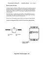
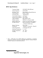
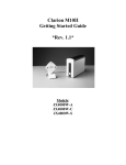
Clarion/Hyperlink Bridge Kit
Installation Manual
Rev. A Page 1
Hyperlink/Clarion
M10II
Extended Range Wireless LAN Bridge Kit
Featuring the Clarion M10II 10 Mbit/sec Wireless Bridge
Installation Manual
Quick Installation Manual –Page 18
Copyright © 1996, Clarion Corporation of America. All rights reserved. No part of
the contents of this document may be transmitted or reproduced in any form or
by any means without the written permission of Clarion Corporation of America.
Portions Copyright © 1998, Hyperlink Technologies, Inc. All rights reserved
HyperGain and HyperAmp are trademarks of Hyperlink Technologies, Inc.
Hyperlink Technologies, Inc.
Clarion/Hyperlink Bridge Kit
Installation Manual
Rev. A Page 3
Contents
FCC Radio Interference Statement
Introduction
Features of the JX4000
Types of Installations
System Requirements
Kit Contents
Tools Required
M10II Front & Rear Panel Features
Connections & Features of the Amplified Antenna
The DC Power Injector/Lightning Protector
Overall System Configuration
Antenna System Connections
Surveying the Antenna Site
Preparing for System Installation
Mounting & Cabling the Amplified Antenna System
Basic System Checks
Amplifier & DC Power Injector LEDs
M10II LED Diagnostic Displays
Clarion M10II Specifications
Quick Installation Manual
APPENDICES
Antenna Mounting Instructions
Hyperlink Technologies, Inc.
4
5
5
6
7
7
7
8
9
10
11
12
12
13
13
15
15
16
17
18
Appendix A
Clarion/Hyperlink Bridge Kit
Installation Manual
Rev. A Page 4
WARNINGS
The manufacturer assumes no responsibility for damage caused by interference
due to this equipment.
Radio Frequency Interference Statement
USA - Federal Communications Commission (FCC): This device complies
with Part 15 of FCC Rules. Operation of this device is subject to the following two
conditions:
This device may not cause harmful interference.
This device must accept any interference that may cause undesired operation.
Information to User: This device must be installed and used in strict accordance
with the manufacturer's instructions. However, there is no guarantee that
interference to radio communications will not occur in a particular commercial
installation. If this device does cause interference, which can be determined by
turning the host equipment off and on, the user is encouraged to consult the
instruction manual of the host equipment or the local device supplier. In case the
device does cause harmful interference with an authorized radio service, the
user/operator shall promptly stop operating the device until harmful interference
has been eliminated.
The manufacturer is not responsible for any radio or television interference
caused by unauthorized modification of this device or the substitution or
attachment of connecting cables and equipment other than those supplied. The
correction of interference caused by such unauthorized modification, substitution
or attachment will be the responsibility of the user.
Hyperlink Technologies, Inc.
Clarion/Hyperlink Bridge Kit
Installation Manual
Rev. A Page 5
Introduction
The Clarion M10II is a wireless transceiver providing 10 Mbit/sec burst data rate
to support wireless connections in IEEE 802.3 and Ethernet II (TCP/IP) LAN.
Equipped with a Hyperlink Extended Range Amplified Antenna System, the
M10II offers an ultra high-performance long-range building-to-building network
bridge.
The M10II functions as an Ethernet MAU. It uses a state-of-the-art spread
spectrum technology to implement robust 10 Mbps burst transmission. It also
actualizes efficient utilization of frame buffers and coordination of RF and wired
interface traffic to maintain high throughput.
The M10II offers true “Plug and Play” installation. No additional driver software
is required for operation. That is, the M10II can be connected not only to a
computer but also to a hub or to a router.
FEATURES OF THE M10II
The Clarion M10II has the following features:
•
Full wireless Ethernet 10 Mbps data rate.
•
State-of-the-art spread spectrum technology provides
reliable, secure, long range, radio link operation.
•
True “Plug and Play” installation for compatibility with all
802.3 and Ethernet II LAN devices, all operating
systems and all protocol stacks.
Hyperlink Technologies, Inc.
Clarion/Hyperlink Bridge Kit
Installation Manual
Rev. A Page 6
Types of Installations
The type of application will determine which type of kit to install:
Building-to-Building or Tower-to-Tower: Typically these installations will
typically require directional Yagi or Grid Antenna kits.
Central Node in a Multipoint Network or Mobile Network: This type of
installation typically requires an Omni Directional Kit at the central node for 360
degree coverage.
System Requirements
The Clarion/HyperGain™ Amplified Extended Range Bridge Kit provides a
Hyperlink Technologies, Inc.
Clarion/Hyperlink Bridge Kit
Installation Manual
Rev. A Page 7
complete plug-and-play solution for linking buildings in an outdoor environment.
All you need to add is suitable masts or towers and some basic site planning.
Please read this manual in its entirety before beginning the installation.
Kit Contents:
Each Kit contains the following items:
Clarion M10II Radio and DC Power Supply
HyperAmp Remote Mounted Amplifier
HyperGain Antenna (Omni, Yagi, or Grid)
HyperGain DC Power Injector/Lightning Protector
Signal Filter
50 ft. Antenna Cable
4 ft. Jumper Cable
Mounting Hardware
Sealant Tape
Manual
Tools Required:
7/16" open-end wrench or Adjustable Wrench
#12-10 AWG or similar wire (for grounding)
Wire Cutter / Stripper
Pliers
Other Required Equipment:
Suitable mast or tower hardware
Transceiver
Other Helpful Equipment and Tools:
Cellular telephones or Walkie-talkies
Binoculars
Compass
Handheld GPS
Hyperlink Technologies, Inc.
Clarion/Hyperlink Bridge Kit
Installation Manual
Rev. A Page 8
M10II Front and Rear Panel Features
Internal antenna
(inside of the top
cover)
MAU port
MAU LED
TX LED
External antenna port
RX LED
Power LED
DC 6.2V port
Power Switch
FCC Certification label
(bottom)
Hyperlink Technologies, Inc.
Clarion/Hyperlink Bridge Kit
Installation Manual
Rev. A Page 9
Connections and Features of the Amplified Antenna
Familiarize yourself with the connections and features of the Amplifier Unit:
Mounting Flanges:
Two sets of mounting holes are provided on the amplifier’s mounting flanges for
either mast mounting using the included U-bolts, or bolted directly to a bracket or
other structure.
Power/Transmit Indicator LED:
This LED glows green in receive mode when power is applied to the amplifier,
and it flashes a red/orange color when transmitting.
Radio Connection:
This connection attaches to the DC Power Injector via the antenna feed cable,
and provides both signal and DC coupled power.
Hyperlink Technologies, Inc.
Clarion/Hyperlink Bridge Kit
Installation Manual
Rev. A Page 10
The DC Power Injector/ Lightning Protector
The DC Power Injector (also known as a "Bias-T") is an in-line device which
couples DC power onto a coaxial cable, enabling the cable to carry both RF
(radio frequency) signals and DC power. The amplifier is powered remotely
through the coaxial antenna feed cable by the way of this device. The DC Power
Injector included with the kit also provides integral lightning protection.
The DC Power Injector provides both Power and Remote Transmit Detect
indicator LEDs. The Power LED indicates that the DC Power Supply is
functioning. The Remote Transmit Detect indicator LED detects changes in the
DC current traveling through the antenna feed cable supplying the amplifier.
When the amplifier enters the transmit mode this indicator LED will be
illuminated, providing positive indication that the amplifier is functioning properly.
Hyperlink Technologies, Inc.
Clarion/Hyperlink Bridge Kit
Installation Manual
Rev. A Page 11
Overall System Configuration
The overall system configuration is shown below. Refer to this
diagram while reading the section which follows, and during
system installation.
Transceiver
AUI to 10BaseT
JX-4000
Antenna
Signal Filter
DC Power
Injector
10BaseT
Cable
Amplifier
Antenna
Cable 50ft.
Adapter
Cable 4ft.
DC Power
Supply
Network
Workstation
Hyperlink Technologies, Inc.
Clarion/Hyperlink Bridge Kit
Installation Manual
Rev. A Page 12
ANTENNA SYSTEM CONNECTION
Warning
The M10II may only be operated using one of the approved
antenna kits described herein.
All antenna system
components are equipped with unique connectors.
Although these connectors may look similar to standard
types they are not compatible with them. Attempting to
attach standard connectors to system components can
cause damage to the connectors and attached equipment.
In addition, the M10II External antenna port is equipped
with a special Antenna recognition function which disables
the transmit function in the event a non-approved antenna
system is connected to the radio.
Surveying the Antenna Site
Before beginning system installation, emphasis should be placed on system
planning. It is important that no large obstructions exist near the antenna, such
as retaining walls, chimneys, air-conditioning units or other antenna masts.
These types of objects can have an impact on the antenna system performance.
Plan to mount the antenna as high as possible. You will need enough mast to
elevate the antenna approximately 15 feet above the roof or above any
obstruction that might be in the antenna's signal path.
You will need to identify the location where the antenna cable will be routed. If
you run the antenna cable through the roof, a water-proof fitting will be required.
Consult a building contractor or licensed electrician to help you with the routing if
necessary. Take note of the length of the mast you will need and the type of
mounting hardware required. The amplified antenna kit is shipped with U-Bolt
mounting hardware which should be ideal for mounting the antenna and amplifier
to most types of mast. Also, make plans on how you are going to talk to the
person at the remote antenna while you are going through the antenna alignment
procedure. For example, cellular phones or walkie talkies can be used.
Hyperlink Technologies, Inc.
Clarion/Hyperlink Bridge Kit
Installation Manual
Rev. A Page 13
Preparing for System Installation
Warning: These antennas are designed to be mounted in open areas such
as rooftops or building exterior walls. They are designed to be installed at
least 6 feet away from areas occupied by people. During system operation,
always keep the antenna at least 1 foot away from your head.
Warning: Before performing the following steps make certain that there
are not any power lines within 50 ft. If the mast should fall, either while
installing or during operation, contact with any power lines will be fatal or
result in a fire.
The Antennas are designed to be mounted on an aluminum or steel mast with a
diameter from 1-1/4 inches to 2-1/8 inches. A larger diameter mast would be
suggested for a more durable installation. The system includes a 50 foot
antenna cable.
Note: The antenna cable has proprietary connectors at each end.
Although these connectors resemble standard “N” type connectors, they
will not mate with standard “N” connectors. Never attempt to attach a
device which is not supplied with the kit as it can cause severe damage to
the connectors.
In addition to the kit contents, you will need a ground wire and wire ties.
Mounting and Cabling the Amplified Antenna System:
Note: Different model antenna kits have different mounting requirements and
procedures. Refer to Appendix A in this manual for antenna mounting details.
1. Attach the mast mounting hardware to a solid structure on your building
(e.g., the roof itself, concrete bulkhead, vent pipe).
2. Using the included mounting hardware, secure the antenna to the top
section of the mast (see Appendix A for details) and similarly, install the
amplifier directly beneath the antenna using the included V-bolts.
3. Screw one end of the 50 ft. cable into the connector on the bottom of the
amplifier, and then attach the filter assembly to the amplifier’s top connector.
Then screw the antenna connector onto the other end of the filter assembly.
4. Apply the included sealant tape around the joined connectors to prevent
corrosion from the weather. Wrap the entire connection, overlapping each
layer slightly to ensure a weather-tight seal.
Hyperlink Technologies, Inc.
Clarion/Hyperlink Bridge Kit
Installation Manual
Rev. A Page 14
5. Attach the one end of the antenna ground cable to the antenna mounting
bracket or V-bolt and the other end to a building ground.
6. Very carefully raise the mast and loosely secure it with the mast mounting
hardware. Use the plastic wire ties to tie the antenna cable to the mast
every six to twelve inches.
7. Aim the directional antenna in the direction of the building you will be linked
to. The omni-directional antennas should be mounted vertically and do not
need to be aimed as they radiate in a 360 degree pattern.
8. Tighten the mast mounting screws. Do not do anything that would make it
difficult to change the position of the antenna. It may be necessary to
reposition the antennas while aiming them.
9. Route the antenna cable along the roof to the point where it enters the
building. From the inside, pull the cable through the hole and take up any
excess slack.
10. Attach the end of the 50 ft. antenna cable to the DC Power Injector. Attach
the 4 foot adapter cable between the DC Power Injector and the M10II.
11. Attach a second ground wire to the ground lug on the DC Power
Injector/Lightning Protector and to a good building ground.
12. Connect the M10II to an “AUI-equipped” network hub using an “AUI”
transceiver cable. A nearby network-connected workstation would be useful
during system installation to verify proper operation.
12. First, Plug the 12 VDC power supply into the DC Power injector and then into
the building’s AC power. Next, plug the included 6.2 VDC power supply into
the M10II and then into the building's AC power. Never use power supplies
other than those shipped with the system as it may cause damage to the
radio and/or amplifier. It is further recommended that the AC connections be
made through a commercially available "surge" protector power strip.
Hyperlink Technologies, Inc.
Clarion/Hyperlink Bridge Kit
Installation Manual
Rev. A Page 15
Basic System Checks
Using the system’s diagnostic LEDs, some basic system checks can now be
performed. When the power is applied to the amplifier, the Power/Transmit
indicator LED (found on the bottom corner of the amplifier) glows green. the
Power Indicator LED on the DC Power Injector/ Lightning Protector will also
illuminate green.
When the system is transmitting the amplifier’s LED flashes from green to
red/orange. Also, when the amplifier enters the transmit mode, the remote
transmit LED on the DC power will illuminate red.
Note that the LED indicators may be difficult to recognize in bright sunlight.
Location of diagnostic LEDs on the DC Power Injector and Amplifier:
Hyperlink Technologies, Inc.
Clarion/Hyperlink Bridge Kit
Installation Manual
Rev. A Page 16
M10II LED Diagnostic Display
During power-up, the front panel LEDs on the M10II provide some diagnostic
information. Refer to the table below for LED diagnostic information.
Label
MAU
TX
Color
Green
Red
RX
Green
Power
Red
Description
Indicates MAU signal (upload or download) is active.
1.
During the power-up cycle, it blinks on and off slowly
five times in approximately one second to indicate that
the firmware has passed its integrity; or, it flashes on and
off very rapidly for four or five seconds to indicate that
the firmware has been damaged. No indication described
above is available in some case of hardware failure.
2.
After normal power-up cycle, it Indicates radio
transmission.
3.
During the firmware-uploaded cycle ; refer description
attached on the new firmware.
1.
Indicates radio signal detection.
2.
Sometimes flashes even if no true signal receives
because of optimized false alarm rate.
1.
It turns on at approximately 1/4 second after applying
the power to indicate activation of the unit.
2.
If the hardware check sequence fails, it turns off
automatically at approximately 5 seconds after power on.
Hyperlink Technologies, Inc.
Clarion/Hyperlink Bridge Kit
Installation Manual
Rev. A Page 17
M10II Specifications
Frequency Range:
Carrier Frequency:
Modulation Type:
Chip Modulation:
Processing Gain:
Communication Method:
Channel Access Method:
Type of Interface:
Datalink Interface:
Network Addressing:
RF MAC Protocol:
1.
1
Network Topology:
2400-2483.5 MHz ISM band
2436.07 MHz
Direct Sequence Spread Spectrum
BPSK, 32 Mcps
12dB (Nominal)
Half Duplex
SS-P-CSMA1
MAU (driven by AUI)
IEEE802.3 or Ethernet II MAC
derived from attached NIC (Note-1)
Radio encapsulation of IEEE802.3
or Ethernet II MAC frame.
Peer to peer
Dimensions:
Power Requirement:
Operating Temperature:
Storage Temperature:
Humidity:
148mm(W) × 210mm(D) × 75mm(H)
+6.2VDC @ 2.0A max.
0 ~ +40 C
-20 ~ +60 C
0% ~ 90%
Note 1 M10II has its own MAC address for configuration of operating
parameters. M10II also memorizes single MAC address of attached Network
Interface Card(s) for re-transmission protocol.
Spread Spectrum p-persistent CSMA
Hyperlink Technologies, Inc.
Clarion/Hyperlink Bridge Kit
Installation Manual
Rev. A Page 18
Clarion Quick Installation Manual
A quick installation manual for
Clarion
Amplified and non-amplified systems.
www.hyperlinktech.com
Hyperlink Technologies, Inc.
Clarion/Hyperlink Bridge Kit
Installation Manual
Rev. A Page 19
MATERIAL LIST
•
•
•
•
•
•
•
•
•
•
•
•
•
(2) Clarion M10II Radios
(2) Clarion Power Supplies
(2) AT-MC12T-16 Transceiver
(2) AT-MC12T-16 Power Supplies
(2) Cat 5 cables 7 feet with RJ45
(2) Clarion Adapter Cables
(2) Cables, 50 feet low-loss with integral lightning protection
(2) 2.4 GHz HyperGain Antennas with mounting hardware
(2) HyperAmps *
(2) Power Injectors *
(2) Antenna Mounting Hardware
Sealant Tape
Manual
OS requirements:
The Clarion radios are true transparent bridges so they will work with
all Operating Systems, protocols, IEEE 802.3 and Ethernet II
Tools:
7/16” open-end wrench or adjustable wrench
#12-10 AWG or similar wire (for grounding)
Wire Cutter / Stripper
Pliers
Other Helpful Equipment and Tools
Cellular telephones or Walkie-talkies
Binoculars
Compass
Handheld GPS
*Included with amplified HyperLink systems
Hyperlink Technologies, Inc.
Clarion/Hyperlink Bridge Kit
Installation Manual
Rev. A Page 20
Installation
Hyperlink recommends that you use two computers directly off a
working Network segment to test the operation before the
installation of a long-range link.
The following steps are for two computers that are off of a working
network. Do not power up any equipment until all equipment is
connected.
1. Connect the transceiver to the Clarion radio.
2. Connect the CAT 5 Patch cable from the transceiver to the
computer network card.
3. Connect the Clarion antenna adapter cable to the EXT ANT on the
back of the Clarion radio.
4. Connect the Clarion adapter cable to the lightning protector for
non-amplified and into the DC Power Injector for amplified
systems.
5. Connect the 50 feet of low-loss cable to the DC Power Injector or
lightning protector.
6. Amplified systems only: connect the amp to the end of cable.
7. Connect the Antenna to the end of the cable or for amplified
systems connect to the amp.
8. Now that everything is connected go back and check that all
connectors are tight .
Hyperlink Technologies, Inc.
Clarion/Hyperlink Bridge Kit
Installation Manual
Rev. A Page 21
Power-up
Please follow the the steps below to power up the
equipment.
1. Power on the Clarion radio first. The power button on the front of
the radio is not operational. When the power cord is inserted into
the radio it will power up. The following is the LED sequence that
should appear after you power up the radio (self-test). On power
up the RX light will blink once and about two seconds later the TX
light will blink 5 times, the power light will stay on. If the radio
does this then it has passed the self-test.
2. Now power-up the transceiver –You should have the power led
and the link light on. The cat 5 cable has to be in the transceiver
to get the link light.
3. If you are using an non-amplified system you should be able to
connect to the other computer. For amplified go to step 4.
4. Power-up the DC Power Injector. A green light will come on
verifying that there is power to the PI. Now look at the AMP–it
should have a green LED lit up.
5. Install the antennas and you should be able to connect to the
other computer and transfer files.
Now just follow the same steps to do a long-range link and it should
go trouble free.
Hyperlink Technologies, Inc.
Clarion/Hyperlink Bridge Kit
Installation Manual
Rev. A Page 22
1201 Clint Moore Road
Boca Raton, FL 33487
Technical Support and Sales
Web Site: www.hyperlinktech.com
For technical support: [email protected]
For Sales: [email protected]
Phone:
561-995-2256
Fax:
561-995-2432
Hyperlink Technologies, Inc.