1
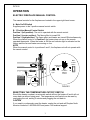
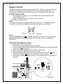
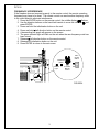
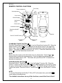
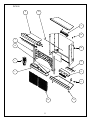
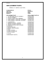
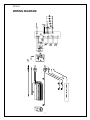
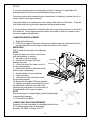
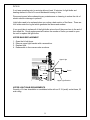
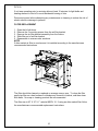
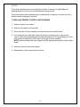
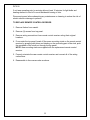
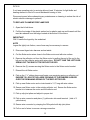
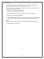
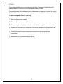
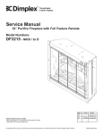
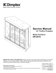
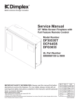
PARTS & SERVICE MANUAL
FOR THE 32” MULTIFIRE™
FIREPLACE
MODEL NUMBER:
DF3215
TABLE OF CONTENTS
OPERATION
PAGE 1
PARTS DRAWING
PAGE 5
PARTS LIST
PAGE 6
WIRING DIAGRAM
PAGE 7
LIGHT BULB REPLACEMENT
PAGE 8
FILTER REPLACEMENT
PAGE 10
REMOTE CONTROL SWITCH BOARD REPLACEMENT
PAGE 11
REMOTE CONTROL RECEIVER REPLACEMENT
PAGE 12
FLAME MOTOR/FLAME ROD REPLACEMENT
PAGE 13
MAIN ON/OFF SWITCH REPLACEMENT
PAGE 15
HEATER ASSEMBLY REPLACEMENT
PAGE 16
POWER CORD REPLACEMENT
PAGE 17
DF3215
OPERATION
ELECTRIC FIREPLACE MANUAL CONTROL
The manual controls for the fireplace are located in the upper right hand corner.
A. Main On/Off Switch
Supplies power to the 3 position manual control switch.
B. 3 Position Manual Control Switch
Position 1 (left position): The unit is operated with the remote control.
Position 2 (center position): The flame effect is turned ON.
Position 3 (right position): The flame effect and heater are turned ON simultaneously.
When the manual control is in Position 3 the heater does not run on the remote
operated thermostat. When the heater is ON the red indicator light is activated on the
firebox and the fan and heater are running on low.
NOTE
When the manual control is in positions 2 and 3, the fireplace unit will not operate with
the remote control.
Main
On/Off
Switch
Initialization
Button
SERIAL No.
XXX
Indicator
Light
XX
3 Position
Manual
Control
FIGURE 1
RESETTING THE TEMPERATURE CUTOFF SWITCH
Should the heater overheat, an automatic switch will turn the heater off and it will not
come back on without being reset. The temperature cutoff switch can be reset by
unplugging the unit, waiting 5 minutes and plugging the unit back in.
CAUTION
If you need to continuously reset the heater, unplug the unit and call Dimplex North
America Limited at 1-800-668-6663 and press 4 for technical support.
1
DF3215
REMOTE CONTROL
The remote control has a range of approximately 50 ft. (15.25m), it does not have to be
pointed at the fireplace and can pass through most obstacles (including walls). It is
supplied with 243 independent frequencies to prevent interference with other units.
BATTERY INSTALLATION
1. Depress tab on the battery cover on the back of the remote transmitter and
remove battery cover.
2. Install 3 AAA batteries into the remote control (included).
3. Replace the battery cover.
NOTE
The remote transmitter has a battery backup time of 24 hours. The batteries can be
removed for up to 24 hours before the transmitter will require re-initialization.
Batteries
FIGURE 2
NOTE
When the Low Battery icon
is present on the remote control it is recommended to
replace the batteries promptly, to maintain full functionality of the remote/fireplace
(FIGURE 5).
INITIALIZING THE REMOTE CONTROL
1. Plug cord into 120 volt wall outlet.
2. Turn ON the electrical power at the circuit breaker.
3. Ensure the Main On/Off switch located inside the fireplace in the upper right hand
corner is in the ON position.
4. Set the 3 position manual control to Position 1 (left position).
5. Press and hold the initialization button on the unit.
6. While holding the initialization button, press the flame/heat ON/OFF
button or
the Purifire™ ON/OFF
button on the remote control transmitter.
7. Release the initialization button on the unit. The remote control is now ready for
operation.
Initialization
Button
SERIAL No.
XXX
XX
Indicator
Light
Main
On/Off
Switch
3 Position
Manual
Control
FIGURE 3
2
DF3215
FREQUENCY INTERFERENCE
If the fireplace does not respond properly to the remote control, the remote operating
frequency may have to be reset. The remote control can send another frequency code
to the circuit board to eliminate interference.
1. Press the ENTER button on the remote control, the middle display
flashes.
2. Use the direction buttons on the hand held remote to move the cursor to
and
press ENTER.
3. Press and hold the initialization button on the unit.
4. Press and hold left direction button on the remote control.
5. A descending bar graph will appear on the screen.
6. The green indicator light will flash on the unit when the new frequency code has
been stored.
7. Release left direction button on the remote control.
8. Release the initialization button on the unit.
9. Press ENTER to return to the main menu.
Initialization
Button
SERIAL No.
XXX
XX
Indicator
Light
Main
On/Off
Switch
3 Position
Manual
Control
FIGURE 4
3
DF3215
REMOTE CONTROL FUNCTIONS
Room temperature
Set temperature
Time of day
Low
Battery
Indicator
Day of week
Remote display
Up direction
button
Enter button
Left direction button
Flame/Heat ON/OFF
button
Right
direction
button
Down
direction
button
Purifire™ ON/OFF button
Occupancy
Sensor
Batteries
Sleep timer
Ambient Light
Sensor
FIGURE 5
FLAME/HEAT ON/OFF BUTTON
Press the Flame/Heat On/Off button
to turn the Flame/Heat function ON. When the
heater function is ON, the icon is displayed on the remote control in the upper left
hand corner. When this icon is displayed, the red indicator light is activated on the
firebox. The default temperature setting is 72°F (22°C). Press the Flame/Heat On/Off
button
to turn the Flame/Heat function OFF.
NOTE
When using the remote control the heater runs on a thermostat. Press the or
direction keys to adjust the set temperature. Once the desired set temperature is
reached the heater will turn OFF. The heater will cycle ON and OFF to maintain the
desired set temperature.
PURIFIRE ON/OFF BUTTON
Press the Purifire™ On/Off button
to turn the Purifire™ function ON. When the
Purifire™ function is ON and the Heater icon is NOT displayed on the remote control,
the green indicator light is activated on the firebox. The default setting for the Purifire™
is set at low speed. Press the Purifire™ On/Off button
to turn the Purifire™ function
OFF.
NOTE
To turn the Flame/Heat and Purifire™ ON or OFF at the same time, press both
control buttons simultaneously.
*For detailed instructions on any of the functions, consult the User’s Guide*
4
DF3215
3
15
2
18
7
12
10
7
3
11
1
6
14
5
13
DF3215
REPLACEMENT PARTS
FIREBOX, 32" - DIMPLEX - MULTIFIRE –
CATALOGUE NO.
PART NO.
MOD LEVEL:
MADE IN:
DF3215
6902520159
NONE
CHINA
REPLACEMENT PART
1. 30” URETHANE LOG SET ASSEMBLY
2. HEATER ASSEMBLY
3. UPPER & LOWER LIGHT ASSEMBLY
4. WIRE HARNESS – RECEIVER TO BLOWER
5. WIRE HARNESS – RECEIVER TO LOGSET
6. FLAME MOTOR
7. REMOTE CONTROL – SENDER
8. REMOTE CONTROL RECEIVER
9. REMOTE CONTROL SWITCH BOARD
10. CORD SET
11. REFLECTOR ROD
12. MIRROR, SEMI-SILVERED
13. FOOT
14. STEEL CURTAIN
15. STEEL CURTAIN ROD
16. BIFOLD DOORS
17. FILTER
18. MAIN ON/OFF SWITCH
REPLACEMENT PART NO.
0439070100RP
2200490500RP
2500200200RP
2500390100RP
2500380100RP
3000240200KIT
3000320100RP
3000320200RP
3000320300RP
4100040400RP
5900080700RP
5900160700RP
8800090100RP
8800240603RP
8800250400RP
6902560100RP
0439060100RP
2800070700RP
6
DF3215
WIRING DIAGRAM
7
DF3215
If unit was operating prior to servicing allow at least 10 minutes for light bulbs and
heating element to cool off to avoid accidental burning of skin.
Disconnect power before attempting any maintenance or cleaning to reduce the risk of
electric shock or damage to persons.
Light bulbs need to be replaced when you notice a dark section of the flame. There are
four bulbs under the log set which generate the flames and embers.
It is a good idea to replace all of the light bulbs at one time if they are close to the end of
their rated life. Group replacement will reduce the number of times you need to open
the unit to replace the light bulbs.
LOWER BULB REPLACEMENT
1. Open the bi-fold doors.
2. Pull the front edge of the plastic ember bed or plastic grate up and forward until the
rear tab releases from the ledge located at the bottom of the mirror.
IMPORTANT
ONLY handle the logset by the emberbed.
NOTE
Logset fits tightly into firebox, some force
may be necessary to remove.
3. Set logset in front of firebox.
Light Bulb
4. Disconnect the logset LED wire
LED Wire
harness from unit.
Harness
5. Lift the left side of the flame rod out of
the mounting bracket.
6. Examine the bulbs to determine which
bulbs require replacement.
7. Unscrew bulbs counter clockwise.
8. Insert new bulbs.
9. Install the left side of the flame rod to
the mounting bracket.
10. Reconnect the logset LED wire harness.
11. Replace the logset by inserting the front of
Logset
the emberbed under the front edge of the
fireplace and push down on the rear edge of
the emberbed until it snaps into place.
NOTE
Ensure the logset is installed tightly under the back ledge
to prevent light leakage.
12. Close the bi-fold doors.
LOWER LIGHT BULB REQUIREMENTS
Quantity of 4 clear chandelier or candelabra bulbs with an
E-12 (small) socket base, 60 watt rating.
Example: GE 60BC or Philips 60 CTC.
8
DF3215
If unit was operating prior to servicing allow at least 10 minutes for light bulbs and
heating element to cool off to avoid accidental burning of skin.
Disconnect power before attempting any maintenance or cleaning to reduce the risk of
electric shock or damage to persons.
Light bulbs need to be replaced when you notice a dark section of the flame. There are
four bulbs under the log set which generate the flames and embers.
It is a good idea to replace all of the light bulbs at one time if they are close to the end of
their rated life. Group replacement will reduce the number of times you need to open
the unit to replace the light bulbs.
UPPER BULB REPLACEMENT
1.
2.
3.
4.
Open the bi-fold doors.
Remove upper light bracket with a screwdriver.
Replace bulb.
Reassemble in the reverse order as above.
Upper Light
Screw
Upper Light Bracket
UPPER LIGHT BULB REQUIREMENTS
Quantity of 2 clear chandelier or candelabra bulbs with an E-12 (small) socket base, 25
watt rating.
9
DF3215
If unit was operating prior to servicing allow at least 10 minutes for light bulbs and
heating element to cool off to avoid accidental burning of skin.
Disconnect power before attempting any maintenance or cleaning to reduce the risk of
electric shock or damage to persons.
FILTER REPLACEMENT
1. Open the bi-fold doors.
2. Remove the 3 mounting screws from the air filter bracket.
3. Remove the air filter bracket assembly from the firebox.
4. Slide filter out of air filter bracket.
5. Reassemble in reverse order as above.
NOTE
If after market air filter is used ensure it is installed according to the manufacturers
recommended instructions.
The filter should be cleaned or replaced on average once a year. To clean the filter
gently tap filter on a hard surface to dislodge any loose dirt or debris, and then clean
with water. No soap or cleaning products are recommended.
The filter size is 20” X 10” X 1” rated at MERV 10. If using an after market filter follow
the manufacturers recommended replacement instructions.
10
DF3215
If unit was operating prior to servicing allow at least 10 minutes for light bulbs and
heating element to cool off to avoid accidental burning of skin.
Disconnect power before attempting any maintenance or cleaning to reduce the risk of
electric shock or damage to persons.
TO REPLACE REMOTE CONTROL SWITCH BOARD
1. Remove firebox from mantel.
2. Remove (8) screws from top panel.
3. Disconnect the 10” wire harness from the remote control switch board.
4. From under the trim assembly, break off the two mounting studs on the remote
control switch board by grasping with pliers and twisting on the protruding part of the
stud, push the remainder of the studs out through the trim assembly.
NOTE: New mounting studs are supplied with the replacement remote control switch
board.
5. Remove remote control switch board.
6. Reassemble in the reverse order as above.
11
DF3215
If unit was operating prior to servicing allow at least 10 minutes for light bulbs and
heating element to cool off to avoid accidental burning of skin.
Disconnect power before attempting any maintenance or cleaning to reduce the risk of
electric shock or damage to persons.
TO REPLACE REMOTE CONTROL RECEIVER
1. Remove firebox from mantel.
2. Remove (8) screws from top panel.
3. Remove wiring connections from remote control receiver noting their original
locations.
4. From under the top panel, break off the seven mounting studs on the remote control
receiver by grasping with pliers and twisting on the protruding part of the stud, push
the remainder of the studs out through the top panel.
NOTE: New mounting studs are supplied with the replacement remote control
receiver.
5. Properly orientate the new remote control receiver and connect all of the wiring
connections.
6. Reassemble in the reverse order as above.
12
DF3215
If unit was operating prior to servicing allow at least 10 minutes for light bulbs and
heating element to cool off to avoid accidental burning of skin.
Disconnect power before attempting any maintenance or cleaning to reduce the risk of
electric shock or damage to persons.
TO REPLACE FLAME MOTOR/FLAME ROD
1. Open the bi-fold doors.
2. Pull the front edge of the plastic ember bed or plastic grate up and forward until the
rear tab releases from the ledge located at the bottom of the mirror.
IMPORTANT
ONLY handle the logset by the emberbed.
NOTE
Logset fits tightly into firebox, some force may be necessary to remove.
3. Disconnect logset wire harness and set aside.
4. Cut the flicker motor wires close to the flicker motor end with wire cutters.
5. Remove the reflector rod from the flicker motor by pulling the end of the rod to the
left and cut the reflector spring with wire cutters. DO NOT TAKE THE LEFTOVER
SPRING OFF THE END OF THE REFLECTOR ROD
6. Remove the (2) screws securing the flicker motor to the flicker motor bracket.
7. Discard the old flicker motor.
8. Pick up the 1 ½” rubber sleeve and locate over remaining spring on reflector rod.
ENSURE TO LOCATE THE LARGE OPENING OF THE RUBBER SLEEVER
OVER THE REMAINING SPRING OF THE REFLECTOR ROD.
9. Pick up new flicker motor and cut wire leads to 3 ½” long with wire cutters.
10. Secure new flicker motor to the existing reflector rod. Ensure the flicker motor
bracket is in between the motor and the reflector rod.
11. Pick up slip joint pliers and adjust to proper slot.
12. Pick up wire connector and place (1) yellow wire into each terminal. (total of 2
yellow wires)
13. Secure wire connector by crimping the 3M symbol with slip joint pliers.
14. Pull on end of wires to ensure a strong connection.
13
DF3215
If unit was operating prior to servicing allow at least 10 minutes for light bulbs and
heating element to cool off to avoid accidental burning of skin.
Disconnect power before attempting any maintenance or cleaning to reduce the risk of
electric shock or damage to persons.
TO REPLACE FLAME MOTOR/FLAME ROD
15. Repeat this process for the (4) remaining wires. (red, blue, orange, grey)
16. Reconnect the logset LED wire harness.
17. Replace the logset by inserting the front of the emberbed under the front edge of the
fireplace and push down on the rear edge of the emberbed until it snaps into place.
NOTE
Ensure the logset is installed tightly under the back ledge to prevent light leakage.
18. Reassemble in the reverse order.
14
DF3215
If unit was operating prior to servicing allow at least 10 minutes for light bulbs and
heating element to cool off to avoid accidental burning of skin.
Disconnect power before attempting any maintenance or cleaning to reduce the risk of
electric shock or damage to persons.
TO REPLACE MAIN ON/OFF SWITCH
1. Remove firebox from mantel.
2. Remove (8) screws from top panel.
3. Remove wiring connections from main on/off switch noting their original locations.
4. Depress the retainer clips on the rear of the switch and push the switch out of the
rear cover.
5. Properly orientate the new switch and connect all of the wiring clips and
connections.
6. Reassemble in the reverse order as above
15
DF3215
If unit was operating prior to servicing allow at least 10 minutes for light bulbs and
heating element to cool off to avoid accidental burning of skin.
Disconnect power before attempting any maintenance or cleaning to reduce the risk of
electric shock or damage to persons.
TO REPLACE HEATER ASSEMBLY
1. Remove firebox from mantel.
2. Remove (8) screws from top panel.
3. Remove wiring connections from heater assembly noting their original locations.
4. Remove cutout wire from JP15 location on the remote control receiver board.
5. Remove (4) heater assembly mounting screws from top panel.
6. Remove (2) heater assembly mounting brackets from heater assembly.
7. Reassemble in the reverse order as above.
16
DF3215
If unit was operating prior to servicing allow at least 10 minutes for light bulbs and
heating element to cool off to avoid accidental burning of skin.
Disconnect power before attempting any maintenance or cleaning to reduce the risk of
electric shock or damage to persons.
TO REPLACE POWER CORD
1. Remove firebox from mantel.
2. Remove (8) screws from top panel.
3. Locate and disconnect the power cord wiring from the main on/off switch and from
the remote control receiver noting their original locations.
4. With needle nose pliers grasp the power cord strain relief grommet from inside the
rear panel and push while twisting to remove.
5. Pull the power cord out through the hole in the rear cover.
6. Install the new cord set through the hole in the rear cover by placing the strain relief
over the cord, hold the strain relief with pliers and slide into mounting hole.
7. Connect all of the wiring connections in their original locations on the main on/off
switch and the remote control receiver.
8. Reassemble in the reverse order as above.
17