1
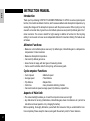
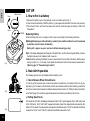
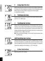
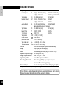
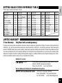
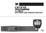
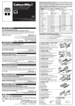
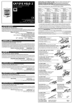
00
15 0
0
12 0
0
9
0
0
6
0
30
0
0
-300
-600
-900
0
-1200
-15
t
•K
•M
••
m
ile
/h
M
CC-AT100
WITH ALTIMETER FUNCTION
50
40
30
20
10
0
-10
-20
-30
-40
-50
••
®
Fee
/h
ile
Km
®
0
00
15 00
7
4
1 00
4
14 00
1
14 00
8
13 00
5
13 00
2
3
1 00
9
12 00
6
2
1 00
3
12 00
0
12
50
0
49 Me
0 ter
48
0
47
0
46
0
45
0
44
0
43
0
42
0
41
0
40
0
INSTRUCTION MANUAL
E
Introduction
Thank you for purchasing CATEYE CYCLOCOMPUTER Model CC-AT100. As well as cyclocomputer
function, this model has altimeter function, which measures altitude and atmospheric temperature, by
sensing the changes of the atmospheric pressure with the pressure-sensor. When cycling in a hilly
area with a mountain bike, it gives the current altitude (above sea level) and trip altitude gain in the 1
meter resolution. The screen is backlit for night viewing. In addition to functions for the bicycling
activity, it can be used on its own as an independent altimeter for mountain climbing. The features are
as follows:
Altimeter Functions:
• Measures current altitude (above sea level), trip altitude gain, total altitude gain in a temperaturecompensated 1 meter resolution.
• Measures atmospheric temperature.
• Can reset trip altitude gain alone.
• Gives choices of usage, with two types of measuring modes.
• Can be used for activities other than bicycling, with accessory parts.
Cyclocomputer Functions:
•
•
•
•
•
Current speed
• Maximum speed
Average speed
• Total distance
Trip distance
• Elapsed time
Clock time
• Auto (Automatic start/stop) function
Can reset maximum speed, average speed, trip distance, elapsed time.
Aspects of Main Unit:
• The screen backlight enables you to read the computer screen even at night.
• Any data stored in memory (total distance, total altitude gain, wheel circumference etc.) will not be
lost with an all-clear operation or by changing the battery.
Before operating, thoroughly familiarize yourself with this manual so that you understand the functions completely. Please keep this manual, along with the warranty card, for future reference.
2
INDEX
Names -------------------------------------------------------------------------------------------- 4
For Safe Operations (Important) ----------------------------------------------------------- 5
Set Up
1. How to Put in a Battery -------------------------------------------------------- 6
2. Main Unit Preparation --------------------------------------------------------- 6
Button Functions ------------------------------------------------------------------------------- 7
How to Use as an Altimeter
1. Altimeter Function -------------------------------------------------------------- 9
2. Cycling Mode ------------------------------------------------------------------ 10
3. Continuous Measuring Mode ---------------------------------------------- 10
4. How to Switch on/off the Bicycle Symbol ------------------------------- 10
5. How to Correct the Current Altitude -------------------------------------- 10
How to Use as a Cyclocomputer
1. Mounting to Bicycle ---------------------------------------------------------- 11
2. Auto (Automatic Start/Stop) Function ----------------------------------- 12
3. Power Saving Function ----------------------------------------------------- 13
Measuring and Display --------------------------------------------------------------------- 13
Troubleshooting ------------------------------------------------------------------------------ 15
Daily Care ------------------------------------------------------------------------------------- 17
Spare Accessories -------------------------------------------------------------------------- 17
Specifications --------------------------------------------------------------------------------- 18
Setting Values Cross Reference Table ------------------------------------------------ 19
Limited Warranty ---------------------------------------------------------------------------- 19
E
3
NAMES
E
Main Unit
A Display
1 Main Display
2 Sub Display
3 Bicycle Symbol
4 Altitude Symbol
5 Mode Symbol
6 Speed Scale Symbol
7 Temperature Scale Symbol
8 Auto (Automatic Start/Stop)
Function Symbol
B S/S (Start/Stop) Button
C Mode Button
D Light Button
E Set Button
F AC (All Clear) Button
G Battery Cover
H Contact
I Altitude Sensor Cover/Filter
3
D
B
E
1
6 7
A
G
AT
4 5
C
2
8
S
O
Q
T
K
L
Accessories/Attachments
4
Bracket
Wire
Speed Sensor/Sensor Holster
Sensor Band A (Large/Small)
Sensor Band B
Sensor Screw
H
I
P
J
M
J
K
L
M
N
O
F
P
Q
R
S
T
Magnet
Sensor Band Rubber Pad
Bracket Rubber Pad (2 pcs.)
Wire Securing Tape
Lithium Battery (CR2032)
N
R
FOR SAFE OPERATIONS (IMPORTANT)
For safe and appropriate use, always observe the following.
Caution:
E
• Don't pay too much attention to your cyclocomputer functions when riding. Keep your eyes on the road and give due
consideration to safe riding.
• This altimeter is not intended to be a specialized measuring device.
Proper use and care:
• Never disassemble the main unit. It can not be re-assembled.
• The main unit is loaded with sensitive components. A strong impact may result in malfunction. Don't intentionally submerge the
main unit under water. Although the main unit is water-resistant (such as rain), it is not designed to be used underwater.
• Don't leave the main unit exposed to direct sunlight for extended periods of time.
• If the main unit is superheated by direct sunlight, the temperature sensor inside of the main unit will not give the correct temperature.
• The Cat Eye CC-AT100 is essentially a barometer. It measures the change in barometric pressure whether caused by a change in
altitude or a change in weather.
• The current altitude should be calibrated before each ride.
• Sudden temperature change can cause a temporary incorrect altitude display.
• When using this unit as an independent altimeter, switch off the bicycle symbol to allow it in the continuous measuring mode.
• Static electricity might cause incorrect data.
• If the S/S(Start/Stop) button, Mode button and Set button are pressed simultaneously, all the stored data will be erased.
• In an aircraft, the unit will not give a correct data because of the regulated pressure.
Maintenance:
• When the main unit or the contact gets wet, dry it off with a cloth; rust will cause functional errors.
• Fasten the magnet and the speed sensor securely, and check their relative position periodically. Incorrect attachment of these
parts may cause an accident.
• If the altitude sensor cover is clogged with mud or sand, it will stop measuring accurately. Clean it off according to "Daily Care"
instructions.
• If the main unit or accessories/attachments become dirty with mud etc., gently wash with mild soap and wipe dry with a soft cloth.
Never apply paint thinner, benzine or alcohol; damage will result.
5
SET UP
E
Close
Battery Cover
1. How to Put in a Battery
1. Remove the battery cover on the back with a coin or a similar opener (Fig. 1).
2. Insert a new lithium battery (CR2032) with the (+) pole upward as illustrated. Close the cover securely.
3. Press the AC button, and reset the speed scale and the clock time again according to "Main Unit
Preparation".
Open
CR2032
Replacing Battery
When the battery has worn out, replace it with a new one according to the following instruction.
Warning: Safely dispose of the old battery; and don't place it within children's reach. If swallowed
by mistake, consult a doctor immediately.
Battery Life: approx. one year (one hour's altitude measuring per day)
Note: If the display disappears with the press of the light button, or often shows irregular altitude, it means
the battery has worn out. Replace it with a new one.
Caution: Before replacing the battery, be sure to leave the unit for more than 5 minutes so that the power
saving function is on; in this way, it will update the data and memorize the newest measurements.
(Refer to page 13: "Power Saving Function".)
Fig.1
2. Main Unit Preparation
The following process must be completed before starting to use.
-1. How to Measure Wheel Circumference
L
Fig.2
In order to get the accurate value, measure the wheel circumference (L) actually from the tire of your
bicycle (Fig. 2). Put a mark on the tire tread, and ride one full wheel revolution; then mark the ground at the
end of one revolution and measure the distance between the two marks. Or, "Setting Values Cross Reference Table" (page 19) can tell the approximate wheel circumference according to the tire size.
-2. Setting Speed Scale
Fig.3
6
First, press the AC button; all displays illuminate and then "km/h" symbol appears (Fig.3). With each press
of the S/S button, "km/h" and "mile/h" appears alternately. Select the desired scale and press the Set
button to fix the scale. This speed scale corresponds to the altitude scale; if "km/h" is selected, the altitude
scale will be "meter", and if "mile/h" is selected, the altitude scale will be "feet".
-3. Setting Temperature Scale
When the process of setting speed scale is completed, "°C" symbol illuminates (Fig. 4). With each press of
the S/S button, "°C" and "°F" appears alternately. Select the desired scale and press the Set button to fix the
scale.
E
Fig.4
-4. Setting Wheel Circumference
The preset value of this unit is 203 cm (standard value for 26 x 1.50 mountain bike wheel) (Fig. 5). When
using 203 cm without revision, press the Set button and this value is set. For revision, press the S/S button
to increase the number and the Mode button to decrease, when the number is blinking. To increase/decrease the number rapidly, hold down the button. When the desired number appears, press the Set button
and the value is set.
Note: Once the wheel circumference is set, this number will be the initial value.
Fig.5
How to Reset or Change the Wheel Circumference
In the sub mode showing O (total distance), and when the current speed is zero, press the Set button; the
stored number flickers. Then revise the number according to the above -4.
-5. Switching on the Auto (Automatic Start/Stop) Function
AT
Fig.6
Fig.7
Operate the Mode button to display the main mode showing T, D or A. Press the S/S button to get the stop
state, and then press the Set button. AT symbol appears and the Auto function is on (Fig. 6).
-6. Setting Clock Time
Operate the Mode button to display the sub mode showing clock time. When the speed is zero, press the
Set button (Fig. 7). With each press of the S/S button, the flickering digits for hours increase by one. (To
increase rapidly, hold down the button.) Then press the mode button, and the digits for minutes flicker.
Adjust the minutes by pressing the S/S button. For accurate time setting, display the number which is 1
minute ahead of the present time; then at the tone of the time signal, press the Set button. (This 12-hour
clock does not have a distinction between A.M. and P.M..)
BUTTON FUNCTIONS
A
Mode Button (Lower Button)
• With each press of this button, the main mode shifts as shown in Fig. 9. In this mode, the main display
(upper line) always shows the current speed.
7
E
• Each main mode has its respective sub mode. To switch to the sub mode, hold down this button. To
switch back to the main mode from the sub mode, just press this button ordinarily. To shift from one
mode to another, it is necessary to switch back to the main mode (from the sub mode) each time.
B
B
D
C
A
C
Fig.8
S/S (Start/Stop) Button (Upper Button)
• With each press, this button starts or stops measuring trip distance (D), elapsed time (T) and
average speed (A). During operation, the speed scale symbol or temperature scale symbol
flashes.
• In the Auto (automatic start/stop) function [when AT symbol is on], this button does not work (refer
to page 12).
Light Button (Right Side Button)
• With each press, the display is backlit for approx. 3 seconds.
D
Set Button (Left Side Button)
How the mode shifts by the MODE button This button is used for the following operations:
MAIN MODE
Current Speed
Current
Altitude
SUB MODE • For correcting the current altitude
Trip Alt.Gain
x1000 Total
Alt.Gain
Current Speed
T Elapsed
Time
Current Speed
Current Speed
A Average
Speed
Current Speed
M Max.
Speed
Current Speed
D Trip
Distance
°C/°F Temp.
O Total
Distance
12-Hour
Clock
Press ordinarily
Fig.9
8
Hold down
mode (but only when the current speed is zero) ---- refer to page 10
press this button in the
• For shifting the altitude measuring mode
press this button in the total altitude and the trip altitude gain mode ---------------- refer to page 10
• For switching on/off the Auto (automatic start/stop) function
press this button in T, D or A mode (but only in complete stop state) -------------- refer to page 12
• For changing the wheel circumference
press this button in O (total distance) mode (but only when the current speed is zero)
--------------------------------------------------------------------------------------------------------- refer to page 7
• For setting clock time
press this button in the clock time mode (but only when the current speed is zero) ---- refer to page 7
AC (All Clear) Button (on the back)
This button erases the data stored in memory. Press this button when setting up the unit for bicycle
for the first time, or when irregular display occurs. After pressing this AC button, all displays illuminate and then only the "km/h" symbol appears. The accumulated data (total distance and total altitude gain) and the stored wheel circumference are not deleted by this operation. After this operation,
only the speed scale, temperature scale and clock time must be set again, according to "Main Unit
Preparation" (refer to page 7).
Reset
When the S/S button and the Mode button are pressed simultaneously, the following data can be reset, depending on the mode.
For resetting trip distance(D), elapsed time(T), average speed(A) and maximum speed (M):
E
In other modes than altitude measuring mode, press the two buttons simultaneously; then the data of D, T, A and M returns to zero.
For resetting the trip altitude gain:
In the sub mode showing the trip altitude gain and total altitude gain, press the two buttons simultaneously; then the data of the trip altitude
gain( ) returns to zero.
For resetting the current altitude correction value:
In the main mode showing the current altitude (
), press the two buttons simultaneously; then the current altitude correction value will be
zero and the data will be reset to the initial value of "International Standard Atmosphere" (ISO 2533).
HOW TO USE AS AN ALTIMETER
Correlation between above sea
level and pressure
extract from ISO 2533 (Table 1)
A.S.Level Pres. A.S.Level Pres.
4500 m 577 hPa 600 m 943 hPa
4000 m 616 hPa 500 m 955 hPa
3500 m 658 hPa 400 m 966 hPa
3000 m 701 hPa 300 m 978 hPa
2500 m 749 hPa 200 m 989 hPa
2000 m 795 hPa 100 m 1001 hPa
1500 m 845 hPa
0 m 1013 hPa
1000 m 899 hPa –100 m 1025 hPa
900 m 910 hPa –200 m 1038 hPa
800 m 921 hPa –300 m 1050 hPa
700 m 932 hPa
1. Altimeter Function
This unit, loaded with a pressure sensor, measures the altitude by using atmospheric pressure. It estimates the altitude by using the "correlation between altitude and pressure" of ISO 2533, based on the
International Standard Atmosphere of ICAO (International Civil Aviation Organization). Generally, a conventional pressure sensor is affected by temperature and gives errors; but this unit is temperature-compensated every 20 seconds and records 1 meter resolution. Also, with a conventional altimeter, altitude
data at the same venue varies from time to time because it is affected by the change of the pressure;
however, the CATEYE CC-AT100 is not affected by pressure changes when not cycling. It measures three
types of altitude data simultaneously: above sea level (current altitude), trip altitude gain (total of altitude
gain from the start to the current point) and total altitude gain (accumulation).
Note: The current altitude data may give an incorrect value temporarily, such as when it is brought from
indoor to outdoor, or when the energy-saving function is released. This is just an influence of the temperature change and is not a malfunction. It will quickly stabilize and return to normal.
The Correlation Between Altitude and Pressure
The higher the altitude gets, the lower the pressure becomes. At venues of which altitudes are under 500m, the pressure decreases by approx.
12hPa per each 100m (Table 1).
Weather and Barometric Pressure Changes
Changes in weather from a HIGH PRESSURE system (clearer, calmer weather) to a LOW PRESSURE system (over-cast, rain, storming
weather) can cause a change in the Altitude reading of 300 feet or more. Thunderstorms or other strong low pressure weather conditions, you
9
E
may cause even a greater change. In seemingly stable weather conditions, you
may expect to see the Altitude fluctuate as much as 100 feet from morning to
evening because of the warming aspects of the sun on the atmosphere.
Fig.10
Pressure change
Symbol on
Altitude
Skipped pressure change
Riding
Neglecting pressure change
Stopped
Riding
Lapse of time
Fig.11
3. Continuous Measuring Mode (Bicycle Symbol: off)
Pressure change
Symbol off
Altitude
Riding
Fig.12
Affected by pressure change
Stopped
Lapse of time
2. Cycling Mode (Bicycle Symbol: on) (Fig. 10)
When using this unit on bicycle, switch on the bicycle symbol. In this way, the
change of the pressure will have an influence on the altitude data only when the
unit perceives the speed signal, regardless of start/stop. Thus, the altitude data
will not be affected even if pressure changes occur while bicycle is stopped. (Fig.
11).
Note: If the pressure changes while riding, the altitude data will give an error.
Riding
When using this unit on its own apart from a bicycle, for hiking etc., switch off the
bicycle symbol. In this way, the altitude data is always influenced by the change of
the pressure (Fig. 12).
• In this mode, if the Auto (automatic start/stop) function is on, the elapsed time
cannot be measured; switch off the AT symbol and operate with the S/S button
in each start/stop. (Refer to "Auto Function", page 12.)
Note: As the pressure changes constantly, the altitude data will give an error to
some extent. * Release the power saving function by pressing the S/S button or
the Mode button.
4. How to Switch on/off the Bicycle Symbol
To switch on(off) the bicycle symbol, first display the sub mode showing trip altitude gain and total altitude gain, with
the operation of the Mode button, and press the Set button. Then press the Set button again, and the bicycle symbol
will be switched on(off).
5. How to Correct the Current Altitude
Air pressure changes constantly, due to various weather conditions. As such, while riding, it is necessary to correct
the altitude. It is recommended to make corrections whenever a reliable index (such as map or peak pointer) is
available.
* The basic knowledge of the altitudes of your house, public facilities, etc. will be useful information for correction.
10
How to Correct the Altitude
First display the main mode showing
, with the operation of the Mode button. Press the Set
button when the speed is zero, and it turns to the correction mode (Fig.13). The figure increases with
each press of the S/S button, and decreases with each press of the Mode button. To increase/
decrease the number rapidly, hold down the button. Adjust the figure to the correct altitude, and
press the Set button to complete this operation.
Fig.13
E
HOW TO USE AS A CYCLOCOMPUTER
Sensor Band B
1. Mounting to Bicycle
Magnet
Rubber Pad
Spoke
Parallel
Sensor Band A
Fig.14
Fig.15
Marking Line of Sensor
Speed Sensor
Fig.16
Magnet
Sensor Band B
Speed Sensor
Center of
the Magnet
Front Fork
Sensor Holster
Fig.17
About 2 mm
Fig.18
• Attach the magnet on the right spokes of the front wheel. The
spokes must run correctly through the inside of the magnet as
in Fig. 14.
• Attach the speed sensor and sensor holster with sensor bands
A/B to the right fork. Choose a band that fits the fork diameter
(S size for up to 24 , L for oversize).
1. Insert the band B into the slit of the band A, and put the rubber pad inside of the band A (Fig. 15). Adjust the length in
order that the screw-fastening part of the bands are parallel
when mounted to the fork (Fig. 16). *To pull out the band B
from the band A, tug strongly.
2. Mount the adjusted bands to the fork along with the speed
sensor and sensor holster, by temporarily tightening the
screw (Fig. 17).
3. Align the magnet's center and the sensor's marking line (Fig.
18), and clearance between the magnet and the sensor
should be 2mm (Fig. 19). Then tighten the screw securely.
Cut off the excess of the sensor band B.
Note: If the space between the fork and the spokes are too
narrow, mount the sensor without the holster.
Fig.19
11
Bracket
Bracket
• Secure the wire with the wire securing tape as in Fig. 20. Wind
the wire round the outer cable up to the handlebar. When adjusting the length, be careful that the wire will not hinder handlebar operation.
• By using the rubber pad, attach the bracket close to the handlebar stem (Fig. 21).
E
Wire
Rubber Pad
Fig.21
Mounting Main Unit
Wire Securing
Tape
Slide
Lever
Speed Sensor
Slide the main unit onto the bracket from front until it clicks into
position. The contacts will automatically connect. To remove the
unit, pull it off forward while pushing down the lever (Fig. 22).
Test
Fig.20
Front
Mount the main unit. Spin the wheel to check if the display shows
the speed. If not, adjust the relative positions of the magnet and
the sensor again following the instructions.
Fig.22
2. Auto (Automatic Start/Stop) Function
AT
Fig.23
This function enables the unit to start/stop automatically without operation of the S/S button. In this function, AT symbol appears on the screen (Fig. 23). It starts measuring automatically even when the power-saving function is on.
• In this function, it starts/stops by perceiving revolutions of the wheel, so it stops measuring when the wheel ceases
moving.
• While this function is on, 2 seconds may be elapsed at the moment when the main unit is mounted onto the bracket.
• When using this unit on its own apart from bicycle, switch off this function. Operation of the S/S button is needed.
How to Switch on/off Auto Function
Operate the mode button to display the main mode showing T, D or A. Get the stop state by pressing the Set button;
then AT symbol appears and the Auto function is on. To switch this function off, press the Set button again and
AT symbol disappears.
12
3. Power Saving Function
When the main unit is left without receiving any signal for about 5 minutes continuously, power
supply is shut down and the unit will be in "sleep" state displaying only the clock time (Fig. 24). By
receiving a signal from the wheel, or by pressing the S/S button or the Mode button for over one
second, the unit "wakes up" and the display returns.
• When the Auto function is on ( AT symbol is on), the power saving function will be automatically
released by riding the bicycle.
• When the power saving function is on, the data of trip altitude gain is not updated.
• When the power saving function starts, the unit automatically memorizes the data of the total
distance, total altitude gain and wheel circumference of that moment.
Fig.24
E
MEASURING AND DISPLAY
S
Current Speed
AT
Always displayed on the main display and updated once a second.
0.0(2.6) - 105.9 km/h [0.0(1.6) - 62.9 mile/h]
AT
Displayed on the sub display, in the 1 meter increment. In the scale of "feet", the increment is 5 feet.
–350 - 5800 m [–1050 - 17400 feet]
Current Altitude (Above Sea Level) (Main Mode)
T
AT
Elapsed Time (Main Mode)
Displays the time from the start to the current point on the sub display, in the units of hours, minutes
and seconds. With the Reset operation, it returns to zero.
0:00'00" - 9:59'59"
13
A
E
AT
D
AT
Average Speed (Main Mode)
Displays the average speed from the start to the current point on the sub display. With Reset operation, it returns to zero. When the elapsed time exceeds approx. 34 hours or the trip distance exceeds
2683.30 km [mile], the unit stops calculation of average speed and (E) mark appears.
0.0 - 105.9 km/h [0.0 - 62.9 mile/h]
Trip Distance (Main Mode)
Displays the distance from the start to the current point on the sub display. With Reset operation, it
returns to zero. 0.0 - 2684.3 km [mile]
Trip Altitude Gain (Sub Mode)
AT
Displays the total of altitude gained from the start (i.e. the point where the reset is done) to the
current point, on the main display. The data of altitude loss is not included. When the trip altitude gain
reaches 2,999, it returns to zero and counting begins anew. The altitude symbol illuminates. On the
sub display, total altitude is displayed. With reset operation, it returns to zero. In the scale of feet, the
figure shows 1/10 value. 0 - 2999m [0 - 900 x 10 feet]
Note: After you reach 2,999, reset the display. If you do not reset, the top limit will become shorter
than 2,999 next time.
x1000 Total Altitude Gain (Sub Mode)
AT
Accumulates only the data of the altitude gain of each ride, and displays the figure on the sub display. The data of the altitude loss is not included in this accumulation. The increment is 0.1m [foot]
from the 0.0 to 9999.9 range, and 1m [foot] from 10,000 to up. Not resettable. It is accompanied by
the data of the trip altitude gain on the main display. 0.0 - 16777 x 1000 m [feet]
12-Hour Clock (Sub Mode)
Displays the present time on the sub display.
AT
14
M
AT
Maximum Speed (Sub Mode)
Displays the maximum instantaneous speed on the sub display. With the Reset operation, it returns
to zero. 0.0 (2.6) - 105.9 km/h [0.0 (1.6) - 62.9 mile/h]
E
°C/°F Temperature (Sub Mode)
AT
Measures the current atmospheric temperature in every 20 seconds and displays the figure on the
main display. It is accompanied by the data of the total distance on the sub display.
0 - 50°C [32 - 122°F]
O
AT
Total Distance (Sub Mode)
Counted continuously and displayed on the sub display. The increment is 0.1 km [mile] from the 0.0
to 9999.9 range, and 1 km [mile] from 10000 to up. Not resettable. It is accompanied by the data of
the temperature in the main display. 0.0 - 42949 km [mile]
TROUBLESHOOTING
Short-circuit the Contacts a few times
If a trouble or malfunction occurs, check the following before taking the unit to repair.
How to Check the Main Unit (Fig. 25)
When the current speed does not appear, short-circuit the two contacts on the back with metal
a few times. If the speed display returns, the main unit is in normal condition.
Trouble / Check Items / Remedy
Fig.25
Display response is slow.
Is it the temperature under 0°C (32°F)?
It returns to normal when the temperature rises. It does not affect the data.
No display appears. Or the display disappears when the light button is pressed.
Has the battery worn out? Or is it about to wear out?
Replace it with a new one (CR2032). (*After replacing the battery, be sure to press the AC
button and to reset the speed scale, temperature scale and the clock time again.)
15
E
Incorrect data appears.
The static electricity may cause an incorrect display.
Press the AC button and reset the speed scale and the clock time again.
Current speed does not appear.
Is there anything on the contact of the main unit or the bracket?
Wipe the contact clean.
Is the distance between the sensor and the bracket too far?
Are the magnet's center and the sensor's marking line aligning?
Adjust the position of the magnet and the sensor correctly.
Is the wire broken?
Replace the bracket & sensor part with a new one.
Transmission signal loss in damp or wet conditions.
Water or condensation may collect between the bracket sensor and the computer causing an interruption
in the data transmission.
Wipe the contacts with dry cloth. Contacts can also be treated with a water repellent silicon jell from an
automotive parts or hardware store. Do not use industrial water repellent; it may damage the bracket.
The S/S button does not start/stop measuring.
Is the unit in the Auto function?
In the Auto function, this button doesn't work.
When using the unit apart from bicycle, it doesn't measure altitude.
Is the bicycle symbol on (i.e. is it on the cycling mode)?
Clear off the bicycle symbol, and turn to the continuous measuring mode.
The unit does not measure altitude.
Is there anything clogged in the altitude sensor cover?
Clean it off according to "Daily Care". (If the cleaning still doesn't work, press the AC button; and reset the speed
scale, temperature scale and the clock time.)
The current altitude shows incorrect data.
Is the correction of the current altitude appropriately done?
The current altitude is influenced by the change of the pressure. Make corrections in each ride.
16
DAILY CARE
If the altitude sensor cover is clogged with mud etc., the unit doesn't measure altitude. After the ride
on muddy roads or in the rain, check the situation of the sensor cover according to the following
instruction.
1. Turn the sensor cover counterclockwise with a screwdriver and take it off.
2. Carefully take out the filter inside, and wash the sensor cover and the filter with clean water.
3. Put the filter back as it was, and close the sensor cover.
Note: There is an altitude sensor under the filter. Be sure not to insert pins or sharp objects.
Altitude Sensor Cover
Open
Close
Filter
E
Fig.26
SPARE ACCESSORIES
The following parts are available separately.
#169-6560/#169-6565
#166-5120
#169-9870
#169-6567/#169-6562
#169-6170
#169-6280
#169-9835
#169-9860
#169-6569
#169-9730
#166-5155
#169-6560
#169-6565
#169-6567
#169-6562
#169-6569
#166-5120
#169-6170
#169-6280
#169-9730
#169-9870
#169-9835
#169-9860
#166-5155
#169-9880
Bracket Sensor Kit
Bracket Sensor Kit (Long)
Center Mount Bracket Kit
Center Mount Bracket Kit (Long)
Stem Mount Bracket Kit
Wheel Magnet
Attachment Kit
Universal Sensor Band
Heavy duty Wire and Bracket Sensor Kit
Sensor Holster
Wrist Band
Main Unit Holder
Lithium Battery (CR2032)
Altitude Sensor Cover/Filter
#169-9880
17
SPECIFICATIONS
E
Display Ranges
Current Speed
0.0(2.6) - 105.9 km/h (27 inch)
±0.5 km/h (under 50 km/h)
[0.0(1.6) - 62.9 mile/h
±0.5 mile/h (under 31 mile/h)]
Total Distance
O
0.0 - 42949 km [mile]
±0.1 km [mile]
Maximum Speed
M
0.0(2.6) - 105.9 km/h (27 inch)
±0.5 km/h
[0.0(1.6) - 62.9 mile/h
±0.5 mile/h]
Average Speed
A
0.0 - 105.9 km/h [62.9 mile/h]
±0.5 km/h [mile/h]
(when elapsed time is over 10 minutes)
Trip Distance
D
0.0 - 2684.3 km [mile]
±0.1 km [mile]
Elapsed Time
T
0:00'00" - 9:59'59"
±0.003%
0:00' - 11:59'
±0.003%
12-hr. Clock
Temperature
°C/°F 0 - 50°C [32 - 122°F]
Current Altitude
–350 - 5800 m
(Above Sea Level)
[–1050 - 17400 feet]
Trip altitude gain
0 - 2999 m [0 - 900 x 10 feet]
Total Altitude Gain
x1000 0.0 - 16777 x 1000 m [feet]
Controller
4-bit 1-chip microcomputer (crystal controlled oscillator)
Display
Liquid crystal (with LED backlight)
Sensor
No-contact magnetic sensor (Length of the cord: 70 cm)
Operating Temperature Range 0°C - 40°C [32°F - 104°F]
Storage Temperature Range
–20°C - 50°C [–4°F - 122°F]
Applicable Cycle Size
0 cm - 255 cm (Initial value: 203 cm)
Power Supply/Service Life
Lithium battery (CR2032) x 1 pc./ approx. one year
(one hour's altitude measuring per day)
Dimension/Weight
56 x 52 x 22.5 mm [2-7/32 x 2-1/16 x 29/32] / 41 grams [1.45 oz]
*The specification and design are subject to change without notice.
S
If the S/S button, Mode button and Set button are pressed simultaneously, all the stored
data will be erased. Be careful not to do this operation by mistake.
18
SETTING VALUES CROSS REFERENCE TABLE
*The tire size is marked on both sides of the tire.
TIRE SIZE
16 x 1-3/8
20 x 1.75
24 x 1
24 x 3/4 Tubular
24 x 1-1/8 Tubular
24 x 1-1/4
24 x 1.75
24 x 2.00
24 x 2.125
26 x 1(559mm)
26 x 1(650c)
L(cm)
128
150
175
178
179
191
189
192
196
191
195
TIRE SIZE
26 x 1.25
26 x 1-1/8 Tubular
26 x 1-3/8
26 x 1-1/2
26 x 1.40
26 x 1.50
26 x 1.75
26 x 1.95
26 x 2.00
26 x 2.1
26 x 2.125
L(cm)
195
197
207
210
200
199
203
205
206
207
207
TIRE SIZE
26 x 2.35
27 x 1
27 x 1-1/8
27 x 1-1/4
27 x 1-3/8
650 x 35A
650 x 38A
650 x 38B
700 x 18C
700 x 19C
700 X 20C
L(cm)
208
215
216
216
217
209
212
211
207
209
209
TIRE SIZE
700 X 23C
700 X 25C
700 X 28C
700 X 30C
700 X 32C
700C Tubular
700 X 35C
700 X 38C
700 X 44C
L(cm)
210
211
214
217
216
213
217
218
222
E
LIMITED WARRANTY
2-Year Warranty:
Only Main Unit (excluding battery)
If trouble occurs during normal use specified in this manual, the part is repaired or replaced free of charge. The service must be performed by
CATEYE Co., Ltd., and the product which needs service must be returned to CATEYE Co., Ltd. directly by purchaser. When returning the
product for CATEYE warranty service, pack it carefully, and enclose the warranty certificate and instructions for repair. Please make sure to type
your name and address clearly on the warranty certificate, so that the product can be shipped back to you as soon as the necessary repair/
adjustment is completed. Insurance, handling and transportation charges to our address shall be borne by the person desiring service. Attachments such as batteries, bracket, sensor etc. are not included in this warranty.
Address for service:
CO.,LTD.
2-8-25 Kuwazu, Higashi Sumiyoshi-ku Osaka 546-0041 JAPAN
Attention: CATEYE Customer Service Section
Phone: 81-6-6719-7781
Fax: 81-6-6719-2362
Service & Research Address for United States Consumers:
CATEYE Service & Research Center
1705 14th St. 115 Boulder, CO 80302
Phone: 303-443-4595
Fax: 303-473-0006
Toll Free: 800-5CATEYE
e-mail: [email protected]
19
Copyright© JAN. 1995
CAT EYE Co., Ltd.
CCMWAT1-990423
Printed in Japan
0687383 7
®
CO.,LTD.
2-8-25, Kuwazu, Higashi Sumiyoshi-ku, Osaka 546-0041 Japan
Phone: 81-6-6719-7781
Fax: 81-6-6719-2362
U.S. Pat. Nos. 4633216/4642606/5236759/5226340, Pat. Pending and Design Patented.