1
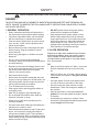
Operator and
Parts Manual
DIXON
Blower Kit
Collection System
539 132250, 539 132251
539 132252, 539 132397
CONTENTS
SAFETY RULES............................................................................................................................4
CARTON CONTENTS ...................................................................................................................7
ASSEMBLY ...................................................................................................................................8
OPERATION................................................................................................................................15
CUSTOMER RESPONSIBILITIES ..............................................................................................16
PARTS .........................................................................................................................................17
CONGRATULATIONS on your purchase of a new
collection system. It has been designed, engineered
and manufactured to give you the best possible
dependability and performance.
Should you experience any problem you cannot easily remedy, contact the nearest authorized
service center/ department. They have competent,
well-trained technicians and the proper tools for
service and repairs.
Read and retain this manual. The instructions will
enable you to assemble and maintain your collection system properly. Always observe the SAFETY
RULES.
KNOW YOUR BLOWER SYSTEM
READ THIS OPERATION MANUAL AND SAFETY
RULES BEFORE ASSEMBLING OR OPERATING
YOUR BLOWER SYSTEM. Compare the illustrations with the carton contents to familiarize yourself
with the parts before starting the assembly. Study
the operating instructions and safety precautions
thoroughly to insure proper functioning of your
Grass Catcher and to prevent injury to yourself and
others. Save this manual for future reference.
WARNING
The operation of any mower can result in
foreign objects thrown into the eyes, which
can result in severe eye damage. ALWAYS
wear safety glasses or eye shields before
starting your mower and while mowing.
We recommend a wide vision safety mask
for over the spectacles or standard safety
glasses.
SAFETY
SAFE OPERATION PRACTICES FOR RIDE-ON MOWERS
DANGER !
THIS CUTTING MACHINE IS CAPABLE OF AMPUTATING HANDS AND FEET AND THROWING OBJECTS. FAILURE TO OBSERVE THE FOLLOWING SAFETY INSTRUCTIONS COULD RESULT IN SERIOUS INJURY OR DEATH.
I. GENERAL OPERATION
•
•
•
•
•
•
•
•
•
•
•
•
•
•
•
•
4
Read, understand and follow all instructions in
the manual and on the machine before starting.
Only allow responsible adults, who are familiar
with the instructions, to operate the machine.
Clear the area of objects such as rocks, stones,
toys, wire etc., which could be picked up and
thrown by the blades.
Be sure the area is clear of all people and pets
before mowing. Stop the machine if anyone
enters the area.
Never carry passengers or children even with
blades off.
Do not mow in reverse unless absolutely
necessary. Always look down and behind before
and while backing.
Be aware of the mower discharge direction and
do not direct it towards anyone. Do not operate
the mower without either the entire grass
catcher or the guard in place.
Slow down before turning.
Never leave the machine unattended when the
engine is running. Always turn off the blades, set
the parking brake, stop the engine and remove
the key before leaving the machine.
Turn off blades when not mowing.
Stop engine before removing grass catcher or
unclogging chute.
Mow only in daylight or good artificial light.
Do not operate the machine while under the
influence of alcohol or drugs.
Watch out for traffic when operating near or
crossing roadways.
Use extra care when loading and unloading the
machine onto a trailer or truck.
Data indicates that operators, age 60 years and
above, are involved in a large percentage of
riding mower-related injuries. These operators
should evaluate their ability to operate the riding
mower safely enough to protect themselves and
others from serious injury.
•
•
DO NOT operate mower with grass catcher,
unless the front weights are installed.
Keep machine free of grass, leaves or other
debris buildup which can touch hot exhaust/
engine parts and burn. Do not allow the mower
deck to plow leaves or other debris which can
cause buildup to occur. Clean any oil or fuel
spillage before operating or storing the machine.
Allow machine to cool before storage.
II. SLOPE OPERATION
Slopes are a major factor related to loss-of-control
and tipover accidents, which can result in severe
injury or death. All slopes require extra caution. If
you cannot back up the slope or if you feel uneasy
on it, do not mow it.
DO
• Mow up and down slopes (10° Max.), not across.
• Remove obstacles such as rocks, tree limbs,
etc.
• Watch for holes, ruts, or bumps. Uneven terrain
could overturn the machine. Tall grass can hide
obstacles.
• Use slow speed. Choose a low speed so that
you will not have to stop while on the slope.
• Use extra care with grass catchers or other
attachments. These can change the stability of
the machine.
• Keep all movement on the slopes slow and
gradual. Do not make sudden changes in speed
or direction.
• Avoid starting or stopping on a slope. If tires
lose traction, disengage the blades and proceed
slowly straight down the slope.
SAFETY
SAFE OPERATION PRACTICES FOR RIDE-ON MOWERS
DO NOT
• Do not turn on slopes unless necessary, and
then, turn slowly and gradually downhill, if
possible.
• Do not mow near drop-off, ditches, or
embankments. The mower could suddenly turn
over if a wheel is over the edge of a cliff or ditch,
or if an edge caves in.
• Do not mow on wet grass. Reduced traction
could cause sliding.
• Do not try to stabilize the machine by putting
your foot on the ground.
IV. SERVICE
•
•
III. CHILDREN
Tragic accidents can occur if the operator is not
alert to the presence of children. Children are often
attracted to the machine and the mowing activity.
Never assume that children will remain where you
last saw them.
• NEVER allow children to operate the
machine.
• Keep children out of the mowing area and under
the watchful care of another responsible adult.
• Be alert and turn off the machine if children
enter the area.
• Before and when backing, look behind and
down for small children.
• Never carry children. They may fall off and be
seriously injured or interfere with safe machine
operation.
• Use extra care when approaching blind corners,
shrubs, trees, or other objects that may obscure
vision.
•
•
•
•
•
•
•
•
•
The operation of any mower can result in
foreign objects thrown into the eyes, which
can result in severe eye damage. Always wear
safety glasses or eye shields while operating
your mower or performing any adjustments or
repairs. We recommend a wide vision safety
mask over spectacles or standard safety
glasses.
Use extra care in handling gasoline and other
fuels. They are flammable and vapors are
explosive.
Use only an approved container.
Never remove gas cap or add fuel with the
engine running.
Allow engine to cool before refueling.
Do not smoke.
Never refuel the machine indoors.
Never store the machine or fuel container
inside where there is an open flame, such
as a water heater.
Never run a machine inside a closed area.
Keep nuts and bolts, especially blade
attachment bolts, tight and keep equipment in
good condition.
Never tamper with safety devices. Check for
proper operation regularly.
Keep machine free of grass, leaves, or other
debris buildup. Clean oil or fuel spillage. Allow
machine to cool before storing.
Stop and inspect the equipment if you strike an
object. Repair, if necessary, before restarting.
Never make adjustments or repairs with the
engine running.
Grass catcher components are subject to wear,
damage, and deterioration, which could expose
moving parts or allow objects to be thrown.
Frequently check components and replace
with manufacturer’s recommended parts, when
necessary.
Mower blades are sharp and can cut. Wrap the
blade(s) or wear gloves, and use extra caution
when servicing them.
Check brake operation frequently. Adjust and
service as shown in the Operator’s Manual.
5
SAFETY
SAFE OPERATION PRACTICES FOR RIDE-ON MOWERS
•
•
•
•
•
•
•
•
•
•
•
•
•
•
•
NEVER allow children to operate the
machine.
Be sure the area is clear of other people before
mowing. Stop machine if anyone enters the
area.
Never carry passengers or children even with
the blades off.
Do not drive in reverse unless absolutely
necessary. Always look down and behind before
and while backing.
Never carry children. They may fall off and be
seriously injured or interfere with safe machine
operation.
Keep children out of the mowing area and under
the watchful care of another responsible adult.
Be alert and turn machine off if children enter
the area.
Before and when backing, look behind and
down for small children.
Mow up and down slopes (10° Max), not across.
Remove obstacles such as rocks, tree limbs,
etc.
Watch for holes, ruts, or bumps. Uneven terrain
could overturn the machine. Tall grass can hide
obstacles.
Use a slow speed while on slope or hill.
Avoid starting or stopping on a slope. If tires
lose traction, disengage the blades and proceed
slowly straight down the slope.
If machine stops while going uphill, disengage
blades, shift into reverse and back down slowly.
Do not turn on slopes unless necessary, and
then, turn slowly and gradually downhill, if
possible.
CAUTION
Look for this symbol to point out important
safety precautions. It means CAUTION!
BECOME ALERT! YOUR SAFETY IS
INVOLVED.
6
CAUTION
In order to prevent accidental starting when
setting up, transporting, adjusting or making
repairs, always disconnect spark plug wire
and place wire where it cannot contact spark
WARNING
Engine exhaust, some of its constituents,
and certain vehicle components contain
or emit chemicals known to the State of
California to cause cancer and birth defects
or other reproductive harm.
WARNING
Battery posts, terminals and related
accessories contain lead and lead
compounds, chemicals know to the State of
California to cause cancer and birth defects
or other reproductive harm. Wash hands
after handling.
UNPACKING INSTRUCTIONS
• Remove all parts and packing materials from
carton.
CONTAINER CONTENTS
TOOLS REQUIRED
•
•
•
•
•
•
•
•
•
Drill and 11/32" drill bit - 3 bag system only
5
/16" Wrench or ratchet and socket
7
/16" Wrench or ratchet and socket
• Drive Pulley
• Belt
• Bag of Hardware
•
Blower Assembly
•
Belt Shield
•
Mounting Assembly
Weight
(not included in 50" Kit 539 132397
or 60" Kit 539 132252)
½" Wrench or ratchet and socket
¾" Socket
Torque Wrench
UPPER CHUTE
Phillips Head Screwdriver
Pliers
BAG DUMP INDICATOR
MIDDLE CHUTE
BELT COVER
BLOWER HOUSING
NOTE: When right hand (RH) and left hand (LH.) are mentioned in this manual, it means when
seated on the mower in the operator’s position.
CAUTION
BEFORE ASSEMBLING GRASS CATCHER TO MOWER:
• Set parking brake.
• Place motion control levers in “NEUTRAL” position.
• Turn ignition key “OFF” and remove key.
• Make sure the blades and all moving parts have completely stopped.
• Disconnect spark plug and place wire where it cannot come in contact with plug.
7
ASSEMBLY
1
INSTALLING DRIVE PULLEY
1. Remove the discharge chute from the deck.
(Deck configuration will vary by size and model)
2. Lower deck to the lowest cutting position.
3. Remove the right hand (discharge side) belt
cover from the deck.
4. Relieve the tension from the deck belt and
remove from the center deck pulley.
(See Operator’s Manual if necessary)
DECK HEIGHT ADJUSTMENT
5. Remove the bolt that secures the right hand
deck pulley to the spindle.
6. Replace right blade shaft with new, longer shaft.
The existing drive pulley and key will fit on the
new shaft. Install blower drive pulley with the
raised portion of pulley hub down. Slide spacer
inside new pulley. Add key to new pulley.
7. Remove two rear bolts from spindle and place
belt shield standoff where the two bolts were
removed. Replace bolts and tighten.
8. Use heavy washer and bolt supplied in kit to
attach pulley to spindle. Torque to 55-75 ft/lbs.
9. Reinstall the deck belt.
NEW BOLT
NEW HEAVY WASHER
DRIVE PULLEY
SPACER
DISCHARGE CHUTE
BELT COVER
BELT SHIELD
STANDOFF
SPINDLE
KEY
REPLACEMENT SHAFT
8
ASSEMBLY
2
MOUNTING BLOWER ASSEMBLY
1. Install the front and rear mount brackets to the
deck with the pin and hairpin cotter supplied with
the kit.
HAIRPIN COTTER
3
INSTALLING DRIVE BELT
1. Make sure the tension release lever is forward
or disengaged.
2. Place the belt over the pulley on the deck. Refer
to illustration for proper routing.
3. Move the tension release lever to the rear and
engage in the latch.
TENSION RELEASE LEVER
OUTER PULLEY
PIN
OUTER PULLEY COVER
REAR OF DECK
TWIST IN BELT
IDLER PULLEYS
9
ASSEMBLY
4
INSTALLING BELT COVERS
1. Place deck belt shield over spindle, aligning hole
with bolt on belt shield standoff.
2. Attach with wing nut to standoff and use tap
screw from kit to attach the other side of the belt
shield to the deck.
3. Place retainer on the outer pulley cover.
4. Align the tab end of the belt cover into the slot
on the deck belt shield and the other end over
the end of the outer pulley cover.
5. Secure with knob.
TAP SCREW
DECK BELT SHIELD
WING
NUT
BELT SHIELD STANDOFF
KNOB
MIDDLE CHUTE LATCH
BELT COVER TAB
RETAINER
DECK BELT SHIELD
OUTER PULLEY COVER
10
ASSEMBLY
5
INSTALLING MIDDLE CHUTE
1. Place middle chute over the top end of the
blower assembly.
2. Latch middle chute to blower assembly.
3. Install the bagger mount tube from the mount kit.
MOUNT STRAP
BLOWER ASSEMBLY
MIDDLE CHUTE
MOUNT STRAP
MOUNT TUBE
RAM MOUNT
6
INSTALLING BAGGER MOUNT
3 Bin Collector
Depending on model, engine guard may have
available mounting holes. If drilling is needed, use
template supplied with kit.
1. Attach template to engine guard at the
corresponding holes as shown in illustration.
With centerpunch, transfer the four 1/8" bagger
mount holes to the engine guard.
2. Remove template and drill four 11/32" holes in
engine guard at locations marked in Step 2 .
3. Remove the front carriage bolts securing the
engine guard.
4. Install kit mount straps between the mount tube
and frame as shown in the illustration. The front
side of the kit mount straps should be on the
inside of the mower frame.
5. Tighten all hardware.
KIT MOUNT STRAP
KIT MOUNT STRAP
TEMPLATE ATTACHMENT
ENGINE GUARD
MOUNT TUBE
1
/8" DIAMETER HOLES
RAM ULTRA MOUNT
11
ASSEMBLY
7
INSTALLING CHUTE SUPPORT
3 Bin System only
1. Position upper chute support against bagger
inlet, flush at outer edges. See Illlustration.
2. Using support as a template, drill two 3/8" holes
into bagger hood.
UPPER CHUTE
SUPPORT
8
INSTALLING WEIGHT KITS
Units with cast weight
1. Bolt one cast weight and two weight brackets
together using four 2¾" bolts and four nuts.
2. Slide both weight brackets over the front tube on
the frame, positioning the assembly in the center
of the frame.
3. Secure with four 3¾" bolts and four nuts.
FRONT TUBE
CAST WEIGHT
BAGGER
HOOD
3¾ BOLT
2¾ BOLT
BAGGER INLET
NUT
WEIGHT BRACKET
3. Secure upper chute support to hood with hex
bolts, washers and nyloc nuts.
FLEX TRIM
NUT
RAM 44
Units with two or more weight plates
1. Bolt weight plates to weight brackets using four
1¾" bolts and four nuts.
2. Slide both weight brackets over the front tube on
the frame, positioning the assembly in the center
of the frame.
3. Secure with four 2¾" bolts and four nuts.
FRONT TUBE
WEIGHT PLATES
2¾ BOLT
HEX BOLT
WEIGHT BRACKET
FLAT WASHERS
1¾ BOLT
RAM 50
12
ASSEMBLY
9
MOUNTING COVER ASSEMBLY
TO SUPPORT ASSEMBLY
NOTE: For ease of assembly, you may wish assistance from another person for mounting the cover
assembly to mower.
1. Position cover assembly on ground behind
mower.
2. Lift and rotate cover to align the cover brackets
with support assembly tubes.
3. Slide the cover down over the support tubes
until secure.
CAUTION
DO NOT operate mower with grass
catcher, unless the front weights are
installed.
NOTE:
Ram Ultra units do not require a weight kit.
COVER ASSEMBLY
SUPPORT
ASSEMBLY
13
OPERATION
TIPS FOR IMPROVED
BAGGING OPERATION
Follow the mower operation instructions in the
mower operator’s manual.
When utilizing the grass catcher on a lawn where
grass and leaf bagging equipment has not been
used, thatch and debris that has accumulated for
long periods of time will be picked up. The amount
collected and the total time of operation may be
greater than experienced with regular use of the
grass catcher.
• Always run throttle at full speed when bagging.
• Select a speed low enough to give good mower
cutting performance, good quality cut and good
bagging performance.
NOTE: It may be necessary to overlap width
of cut to suit your conditions.
• If grass is extremely tall, it should be mowed
twice. The first time relatively high, the second
time to desired height.
• Use left hand side of mower for trimming.
• Plastic trash bags (3.0 mil, 30 gallon) can be
inserted inside grass catcher containers for ease
of debris disposal. To remove the plastic trash
bags when full:
a. Disengage blades, shift into neutral, engage
the parking brake and stop the engine.
b. Unlatch and raise cover.
c. Remove one container at a time by grasping
container handles and pulling toward the
rear, off of the tube rails.
d. With the container resting on the ground,
close and secure the top of the plastic lawn
bag.
e. Tip the container on its side and slide the
filled bag from the container.
f. Install a new plastic lawn bag with the edges
of the bag draped over upper lip of the
container.
g. Repeat for other container.
h. Reinstall containers making sure right
container overlaps left container at center
supports.
i. Close cover and secure latches over center
support tubes.
14
•
•
Avoid cutting wet grass or mowing in the
morning while the dew is still heavy. Grass
clippings collected under these conditions tend
to be sticky and adhere to the walls of the flow
path causing clogging.
If the grass catcher fails to pick up cut grass
or leaves, it is an indication that clogging has
occurred in the system or that the grass catcher
containers are full.
a. Disengage blades, place motion control
levers in neutral position.
- Unlatch and raise cover.
- Slide out containers and dispose of
clippings.
- Replace containers, close cover, and
latch.
b. Unlatch chutes and check for clogging.
- Remove all debris in chute.
- Reassemble and latch chutes.
CAUTION
• DO NOT operate mower with grass catcher
partially installed.
• Disengage blades and stop engine before
leaving mower seat to empty containers,
unclogging chutes, etc.
• Close cover before starting.
• Disengage mower blades when crossing
driveways or gravel surfaces and other
areas where thrown objects could be a
hazard.
• DO NOT attempt to vacuum up cans or
other potentially hazardous projectiles.
CUSTOMER RESPONSIBILITIES
GENERAL RECOMMENDATIONS
STORAGE
Always observe safety rules when performing any
maintenance.
• Before each use check for loose fasteners.
• Clean unit thoroughly after each use.
BLADE CARE
For best results mower blades must be kept sharp.
Replace bent or damaged blades.
• See BLADE CARE instructions in your mower
operator’s manual.
When grass catcher is to be stored for a period
of time, clean it thoroughly, remove all dirt, grass,
leaves, etc. Store in a clean, dry place.
CAUTION
BEFORE PERFORMING MAINTENANCE,
SERVICE OR ADJUSTMENTS:
• Set parking brake.
• Place motion control levers in “NEUTRAL”
position.
• Place clutch control in “DISENGAGED”
position.
• Turn ignition key to “OFF” position.
• Make sure blades and all moving parts have
completely stopped.
• Disconnect spark plug wire(s) from spark
plug(s) and place wire where it cannot come
in contact with plug.
CAUTION
Do not leave grass in bagger containers. Empty
containers after each use and before storing.
Failure to do so may result in spontaneous
combustion which could develop into a fire.
CAUTION
Grass catcher components are subject to wear,
damage and deterioration, which could expose
moving parts or allow objects to be thrown.
Frequently check components and replace
with manufacturer’s recommended parts when
necessary.
15
PARTS
2
12
11
9
4
4
10
8
7
5
4
6
3
3
1
16
5
6
PARTS
ITEM
PART NO.
QTY.
DESCRIPTION
ITEM
PART NO.
QTY.
DESCRIPTION
1.. 539 108081....1 .... SCREW, SPEC 10-14 x ½
7.. 539 108088....1 .... LATCH, HOOD
2.. 539 108082....1 .... BAG DUMP INDICATOR
8.. 539 108089....1 .... PLATED, WELD NUT
1
3.. 539 108083....2 .... SCREW, 10-24 x 1 /8
9.. 539 108141....1 .... CHUTE, UPPER
4.. 539 108084....3 .... WASHER, /16 x ¾
10.. 539 109552....2 .... WASHER 3/16 LOCK
5.. 539 108085....2 .... SPACER, SPLIT
11.. 539 130294....1 .... CHUTE, MIDDLE
6.. 539 108086....2 .... NUT, ACORN 10-24
12.. 539 976952....1 .... SCREW 10-24 x .625 MACH
3
17
PARTS
BAG ASSEMBLY 960 730019
3
2
12
12
1
11
3
8
5
4
10
7
9
6
17
16
15
18
14 13
PARTS
ITEM
PART NO.
QTY.
DESCRIPTION
ITEM
PART NO.
QTY.
DESCRIPTION
1.. 532 192709....1 .... SCREEN, COVER
12.. 539 976977....8 .... NUT, #10-24, CROWNLOCK
2.. 532 195373....1 .... COVER
13.. 539 990627....2 .... HCS, 5/16-18 X 1¼, GR 5
3.. 539 976952....6 .... SCREW, #10-24 x 5/8
14.. 539 990188....4 .... WASHER, 5/16, SAE
4.. 539 108096....2 .... SPRING, RETAINER
15.. 539 990717....2 .... NUT, 5/16-18, NYLOC
5.. 539 108097....4 .... PLUG, TUBING END
16.. 539 110234 ....1 .... SUPPORT, CHUTE
6.. 539 108098....1 .... BAGGER, FRAME
17.. 539 112294 ....1 .... FLEX TRIM
7.. 532 192786....2 .... PIN, HINGE
NOT SHOWN
8.. 532 192550....1 .... GASKET, COVER
539 108447 ...1 .... DECAL, CE
9.. 532 400226....3 .... CONTAINER
539 108163 ...1 .... DECAL, CATCHER
10.. 532 192603...1 .... SEAL, COVER
11.. 532 130895...2 .... HANDLE, BAGGER COVER
960 730019 ...1 .... COVER ASSEMBLY
(INCLUDES ITEMS 1-12)
19
PARTS
46
44
24
47
4
14
15
THIS SIDE
TOWARD BEARING
31
11
55 17
22
59
30
11
21
45
56
38
28
50
16
40
11
48
52
18
34
33
42
19
60 49
15
47
11
56
40
23
46
32
58
14
TORQUE TO
30 LBS
48 41
51
12
26
9
13
25
44
10
50" Deck
2
8
59
36
27
6
43
20
23
35
10
29
5
60" Deck
40
53
12
44
51
20
3
60
39
45
37
36
7
37
57
37
1
36
PARTS
ITEM
PART NO.
QTY.
DESCRIPTION
ITEM
PART NO.
QTY.
DESCRIPTION
1.. 539 101977....1 .... TRACTION SPRING
34.. 539 130337....1 .... ARM, IDLER
2.. 539 976952....1 .... SCREW 10-24 x .625 RD
35.. 539 130338....1 .... ARM, TENSION
3.. 539 104411 ....1 .... KNOB W/STUD
36.. 539 132050....1 .... BRKT, MT, FRONT, 44" DECK
5
4.. 539 104763....1 .... RETAINER /16 “U” TYPE
539 132057 ...1 .... BRKT, MT, FRONT, 50" DECK
5.. 539 105785....1 .... DECAL, WARNING
539 132064 ...1 .... BRKT, MT, FRONT, 60" DECK
6.. 539 106741....1 .... DECAL, SEVERING
37.. 539 132052....1 .... BRKT, MT, REAR, 44" DECK
7.. 539 108084....1 .... WASHER, 3/16 x ¾ x 16 GA
539 132059 ...1 .... BRKT, MT, REAR, 50" DECK
8.. 539 108088....1 .... LATCH, HOOD
539 132066 ...1 .... BRKT, MT, REAR, 60" DECK
9.. 539 108089....1 .... PLATED, WELD NUT
10.. 539 108120....2 .... NUT ¼-20 HEX NYLOC
5
38.. 539 130341....1 .... PLATE, OUTER
39.. 539 130346....1 .... KEEPER
11.. 539 990717....5 .... NUT /16-18 HEX NYLOC
40.. 539 200282....3 .... NUT, 3/8-16 HEX JAM NYLOC
12.. 539 108735....2 .... NUT ¼-20 HEX FLANGE
41.. 539 919078....1 .... IDLER PULLEY
3
13.. 539 109552....2 .... WASH /16 LOCK
42.. 539 976949....1 .... HCS 3/8-16 x 1¾ GR 5
14.. 539 110321 ....2 .... BOLT, HEX 3/8-24 x 1¼ GR 8
43.. 539 976988....1 .... HAIRPIN COTTER
15.. 539 110323 ....2 .... WASHER, HARDENED
44.. 539 990055..13 .... WASHER, ¼ FLAT SAE
16.. 539 113683 ....1 .... V-IDLER
45.. 539 990302....8 .... SCREW, ¼ x 3/8 THRD FRM
17.. 539 115667 ....1 .... KEY, 3/16 x ½
46.. 539 108461....3 .... HCS ¼-20 x ½ GR 5
3
18.. 539 125229....1 .... KEY, /16 x 1½
47.. 539 990118 ....2 .... WASHER, 3/8 SPLT LOCK
19.. 539 130292....1 .... IMPELLER
48.. 539 990122....2 .... WASHER, 3/8 SAE FLT
20.. 539 130293....1 .... COVER, BELT
49.. 539 990209....1 .... HCS 5/16-18 x 1 GR 5
21.. 539 130295....1 .... HUB, BEARING
50.. 539 990316....4 .... RHSNB 5/16-18 x ¾ GR 5
22.. 539 130296....2 .... BEARING
51.. 539 990643....2 .... HCS ¼-20 x 7/8 GR 5
23.. 539 130301....2 .... BUSHING
52.. 539 990655....1 .... HCS 3/8-16 x 1½ GR 5
24.. 539 130309....1 .... COVER, OUTER PULLEY
53.. 539 990692....1 .... WASHER, 5/16 STD FLT
25.. 539 130313....6 .... NUT, 5/16-18 TEE
54.. 539 130349....1 .... DECAL, BELT ROUTING
26.. 539 130314.. 11 .... NUT, ¼-20 TEE
55.. 539 131085....1 .... KEEPER, BELT, OUTER
5
27.. 539 130315....6 .... HCS /16-18 x ½ GR 5
56.. 539 131087....2 .... KEEPER, BELT, REAR
28.. 539 130316....1 .... SHAFT, IMPELLER
57.. 539 132122....1 .... PLATE, BACKING
29.. 539 130317....1 .... PIN
58.. 539 132124....1 .... PLATE, BACKING
30.. 539 130323....1 .... SPACER
59.. 539 910935....1 .... WASHER
31.. 539 130324....1 .... PULLEY
60.. 539 990645....1 .... RHSB, 3/8 -16 x 1
32.. 539 130335....1 .... MOUNT, IDLER, UPPER
33.. 539 130336....1 .... MOUNT, IDLER, LOWER
21
PARTS
26
25
35
5
29
8
27
4
30
12
10
14
34
32
31
28
28
6
6
7
34
3
1
33
12
13
12
28
9
6
7
14
2
20
19
21
12
14
17
24
14
15
18
13
19
15
15
20
23
22
14
18
11
22
16
PARTS
ITEM
PART NO.
QTY.
DESCRIPTION
ITEM
PART NO.
QTY.
DESCRIPTION
1.. 539 132056....1 .... SHIELD, BELT, 44"
18.. 539 990861....4 .... RHSB, 5/16 -16 x 1¾
2.. 539 132063....1 .... SHIELD, BELT, 50"
19.. 539 990645....2 .... RHSB, 3/8 -16 x 1
3.. 539 132070....1 .... SHIELD, BELT, 60"
20.. 539 976979....2 .... NUT, 3/8 -16, NYLOC
4.. 539 132205....1 .... PULLEY SPACER
21.. 539 132196....1 .... STRAP, LEFT,
MODELS: 132252, 132397
5.. 539 132071....1 .... PULLEY, 44"
539 132072 ...1 .... PULLEY, 50"
539 132073 ...1 .... PULLEY, 60"
6.. 539 105743....1 .... DECAL, EURO NO STEP
7.. 539 990209....2 .... HCS, 5/16 -18
8.. 539 132348....1 .... BELT, 44"
539 132347 ...1 .... BELT, 50"
539 130347 ...1 .... BELT, 60"
9.. 539 132256....1 .... STRAP, RIGHT,
MODELS:132250, 132251
10.. 539 132258....1 .... STRAP, LEFT
MODELS:132250, 132251
11.. 539 101331....1 .... NUT, ½, NYLOC
5
22.. 539 132198....1 .... STRAP, RIGHT,
MODELS: 132252, 132397
23.. 539 990646....1 .... HCS, ½ -13 X 1
24.. 539 990316....2 .... RHSB, 5/16 -18 x ¾
25.. 539 115636 ....1 .... WASHER, ½
26.. 539 133070....1 .... HCS, ½-20 x 2½
27.. 539 116196 ....1 .... KEY, OUTER SHAFT
28.. 539 115643 ....3 .... SCREW, #12-14 X ¾, TAP
29.. 539 133040....1 .... BELT SHIELD STANDOFF, 44"
539 133042 ...1 .... BELT SHIELD STANDOFF, 50"
539 133044 ...1 .... BELT SHIELD STANDOFF, 60"
30.. 539 119810 ....1 .... SHAFT, LONG
12.. 539 990717..10 .... NUT, /16-18 HEX NYLOC
31.. 539 110234 ....1 .... SUPPORT, HOSE
13.. 539 131091 ...1 ... TUBE, MOUNT
32.. 539 112294 ....1 .... FLEX TRIM
5
14.. 539 976937 ...6 ... HCS /16 -18 x 2 GR 5
33.. 539 990627....2 .... HCS, 5/16 -18 X 1¼
15.. 539 112899 ....8 .... NUT, 5/16, NYLOC
34.. 539 990188....4 .... WASHER, 5/16, SAE
16.. 539 132192....1 .... MOUNT HITCH, LOWER
35.. 539 990997....1 .... NUT, ¼C, WING, NYLOC
17.. 539 132194....1 .... MOUNT HITCH, UPPER
23
PARTS
WEIGHT KIT 44"
5
3
2
1
4
24
PARTS
ITEM
PART NO.
QTY.
DESCRIPTION
1.. 539 111587 ....1 .... CAST WEIGHT
ITEM PART NO.
QTY.
DESCRIPTION
4.. 539 106492....4 .... HCS 3/8-16 x 2¾
2.. 539 114898 ....2 .... WEIGHT BRACKET
5.. 539 991126 ....4 .... HCS 3/8-16 x 3¾
3.. 539 976979....8 .... NUT 3/8-16, NYLOC
25
PARTS
WEIGHT KIT 50"
4
3
2
1
5
26
PARTS
ITEM
PART NO.
QTY.
DESCRIPTION
ITEM
PART NO.
QTY.
DESCRIPTION
3
1.. 539 113232 ....3 .... WEIGHT PLATE
4.. 539 102612....4 .... HCS /8-16 x 2¾ GR 5
2.. 539 114898 ....2 .... WEIGHT BRACKET
5.. 539 976949....4 .... HCS 3/8-16 x 1¾ GR 5
3.. 539 976979....8 .... NUT 3/8-16 HEX NYLOC
27
HUSQVARNA PRODUCT REGISTRATION INFORMATION & WARRANTY STATEMENT
All Husqvarna products can be registered online at www.usa.husqvarna.com quickly and easily regardless of their model year. Click the Support tab,
then click on the Online Product Registration link, and fill out the electronic form and submit. Ask about Husqvarna s extended service plan!
SECTION 1: LIMITED WARRANTY
Husqvarna Professional Products, Inc (“Husqvarna”) warrants the original purchaser the Husqvarna branded product to which this warranty apply (the “Product”) that the Product shall be free from defects in material and workmanship
from the date of purchase for the period of the applicable “Warranty Schedule” of the Product as set forth below. Additional limitations are described in Section 2 through 6, inclusive.
COMMERCIAL /
RENTAL
CONSUMER
PRODUCT CATEGORY
PROFESIONAL
WARRANTY
WARRANTY SCHEDULE* WARRANTY SCHEDULE
SCHEDULE
Reconditioned Products: Reconditioned chainsaws, trimmers, brushcutters, clearing saws, handheld blowers,
backpack blowers, hedge trimmers, and electrical products.
90 Days
N/A
N/A
Chain Saws Lifetime Ignition Warranty (Parts Only). One Year Conditional Crankshaft Warranty for Commercial/Professional use when operated with
2 Years
90 Days
90 Days
100 Series Trimmers, Stick Edgers, Hedge Trimmers
2 Years
1 Year
90 Days
2 Years
1 Year
90 Days
Blowers (Lifetime Ignition Warranty - Parts Only)
2 Years
2 Years
90 Days
Pole Pruners, Pole Saws, Pole Hedge Trimmers (Lifetime Ignition Warranty - Parts Only)
1 Year
1 Year
90 Days
Residential Walk-Behind Mowers, Tillers, LE389 Edger †
2 Years
N/A
N/A
LE475 Edger †
LT, LTH, LS, XLS, GLS, YT, YTH, GT, GTH, 16H, Pro15, 155 ProFlex Series Lawn & Garden Riders and
Residential Zero Turn Mowers †
2 Years
90 Days
90 Days
2 Years
N/A
N/A
3 Years or 600 Hours
1 Year or 600 Hours
90 Days
5 Years or 1,500 Hours
5 Years or 1,500 Hours
90 Days
90 Days
Husqvarna XP 2 cycle oil (Parts & Labor).
Lifetime Ignition Warranty (Parts Only). Lifetime Shaft Warranty.
200 & 300 Series Trimmers, Brushcutters, Clearing Saws, Stick Edgers, Hovering Trimmers & Hedge Trimmers
Lifetime Ignition Warranty (Parts Only) and Lifetime Shaft Warranty apply to these products (excludes Hovering Trimmers).
MZ and EZ Series Zero Turn Riders †
iZ, LZ, BZ Series Zero Turn Riders † (Applies to units factory-equipped with Roll Over Protection System.)
Commercial Walk Mowers † (includes 21” & wide area)
3 Years
3 Years
Commercial Turf Specialty Equipment †
1 Year
1 Year
1 Year
Zero Turn & Commercial Turf Specialty Attachments
2 Years
1 Year
90 Days
Power Cutters (Lifetime Ignition Warranty - Parts Only)
1 Year
90 Days
1 Year (K750 only)
90 Days
Automatic Mower (1 Year Battery Warranty)
2 Years
90 Days
90 Days
Snow Throwers †
2 Years
90 Days
90 Days
Pressure Washers †
2 Years
Generators (Husqvarna s warranty does not cover Engine & Generator Parts, which are warrantied by responsible manufacturer.) †
Grass Catchers & Bumpers Purchased with New Units
2 Years
(2nd Year Parts Only)
2 Years
(Excludes 5525PW)
2 Years – 1365GN only
(2nd Year Parts only)
1 Year
Parts & Accessories Purchased Separately
30 days
2 Year or 2,000 Hour Powertrain & 1 Year or 1,000 Hour Body Warranty
HUV Batteries: 4210E Versions
4 Year Pro-rated
Husqvarna Safety Apparel***
Batteries**** (Consumer Products where applicable)
Replacement Parts, Accessories including Bars and Chains, Tools and Display Items. Emission Control System Components necessary to
comply with CARB-TIER II and EPA Regulations (Excludes components which are part of engine systems manufactured by third part engine manufacturers for
which the purchaser has received a separate warranty with product at time of purchase.)
N/A
Same Warranty As Unit When Purchased with Unit
Spreaders
Husqvarna Utility Vehicles** (Engines/transmissions shall be warrantied through Husqvarna.)
N/A
90-day
1 year
N/A
30 Day Warranty
IR
Part Number 525 88 56-01
† Refer to Section 3 for items not covered by this warranty
*All consumer product use must have been limited to the owner s residence. Warranted for noncommercial, nonprofessional, noninstitutional and nonincome producing use.
**HUV 2 Year or 2,000 Hour Powertrain (The engine assembly, unitized transaxle assembly (gasoline vehicle), motor, and main frame assembly are warranted with respect to parts and labor against defects in material and
workmanship or a period of two years or 2000 hours of operation, whichever first occurs, from the date of purchase.) & 1 Year or 1,000 Hour Body Warranty (All remaining components of the vehicle not specified otherwise and all
other original equipment options and accessories supplied by Husqvarna are warranted with respect to parts and labor against defects in material and workmanship for a period of one year or 1000 hours of operation, whichever first
occurs, from the date of purchase.)
HUV s Gas & Diesel Powered Battery: 0 – 6 months free replacement and 7 – 12 months prorated
HUV s Electric Powered – 4 year or 16,000 Energy Unit Limited Warranty Period
***Husqvarna safety apparel warranty is from the date of the customer s original purchase for defects in material and workmanship. Normal wear, tear or abuse is not covered under warranty. All care and maintenance instructions
must be followed as stated by the manufacturer on the care label. The fit of the protective apparel/boot is not covered under warranty.
****Battery 1 Year prorated limited warranty with 100% replacement during the first 6 months.
Lifetime Warranty (Parts and Labor): All tiller tines and trimmer shafts against breakage. Proof of purchase required.
Lifetime Warranty (“PARTS ONLY” after initial warranty expiration): Ignition coils and modules on handheld product. Proof of purchase required.
SECTION 2: HUSQVARNA S OBLIGATIONS UNDER THE WARRANTY
Husqvarna will repair or replace defective components without charge for parts or labor if a component fails because of a defect in material or workmanship during the warranty period.
SECTION 3: ITEMS NOT COVERED BY THIS WARRANTY
The following items are not covered by this warranty:
(1) Normal customer maintenance items which become worn through normal regular use, including, but not limited to, belts, blades, blade adapters, bulbs, clutches, clutch drums, filters (fuel line, fuel filters, air filters, oil filters),
sprockets, guide bars, lubricants, rewind springs, saw chain, spark plugs, starter ropes and tiller tines;
(2) Natural discoloration of material due to ultraviolet light;
(3) Engine and drive systems not manufactured by Husqvarna; these items are covered by the respective manufacturer s warranty as provided in writing with the product information supplied at the time of purchase; all claims must be
sent to the appropriate manufacturer.
(4) Lawn and garden attachments that are covered by a third party which gives a warranty, all claims for warranty should be sent to the manufacturer.
(5) Commercial or consumer mowing decks with sand abrasion damage.
(6) Emission Control System components necessary to comply with CARB-TIER II and EPA regulations which are manufactured by third party engine manufacturer.
SECTION 4: EXCEPTIONS AND LIMITATIONS
This warranty shall be inapplicable to defects resulting from the following:
(1) Accident, abuse, misuse, negligence and neglect, including stale fuel, dirt, abrasives, moisture, rust, corrosion, or any adverse reaction due to incorrect storage or use habits;
(2) Failure to operate or maintain the unit in accordance with the Owner s/Operator s manual or instruction sheet furnished by Husqvarna;
(3) Alterations or modifications that change the intended use of the product or affects the product s performance, operation, safety, or durability, or causes the product to fail to comply with any applicable laws; or:
(4) Additional damage to parts or components due to continued use occurring after any of the above.
REPAIR OR REPLACEMENT AS PROVIDED UNDER THIS WARRANTY IS THE EXCLUSIVE REMEDY OF THE PURCHASER. HUSQVARNA SHALL NOT BE LIABLE FOR ANY INCIDENTAL OR CONSEQUENTIAL DAMAGES
FOR BREACH OF ANY EXPRESS OR IMPLIED WARRANTY ON THESE PRODUCTS EXCEPT TO THE EXTENT PROHIBITED BY APPLICABLE LAW. ANY IMPLIED WARRANTY OF MERCHANTABILITY OR FITNESS FOR A
PARTICULAR PURPOSE ON THESE PRODUCTS IS LIMITED IN DURATION TO THE WARRANTY PERIOD AS DEFINED IN THE LIMITED WARRANTY STATEMENT. HUSQVARNA RESERVES THE RIGHT TO CHANGE OR
IMPROVE THE DESIGN OF THE PRODUCT WITHOUT NOTICE, AND DOES NOT ASSUME OBLIGATION TO UPDATE PREVIOUSLY MANUFACTURED PRODUCTS.
Some states do not allow the exclusion of incidental or consequential damages, or limitations on how long an implied warranty lasts, so the above limitations or exclusions may not apply to you. This warranty gives you specific legal
rights, and you may also have other rights which vary by state.
SECTION 5: CUSTOMER RESPONSIBILITIES
The product must exhibit reasonable care, maintenance, operation, storage and general upkeep as written in the maintenance section of the Owner s/Operator s manual. Should an operational problem or failure occur, the product
should not be used. Failure caused by continued use is not covered by warranty. Product should be delivered, at owners expense, as is, to an authorized Husqvarna Servicing Retailer for evaluation. Proof of purchase, as explained
in section 6, rests solely with the customer.
SECTION 6: PROCEDURE TO OBTAIN WARRANTY CONSIDERATION
It is the Owner s and Retailer s responsibility to make certain that the Warranty Registration Card is properly filled out and mailed to Husqvarna. This card should be mailed within ten (10) days from the date of purchase in order to
confirm the warranty and to facilitate post-sale service. Proof of purchase must be presented to the authorized Husqvarna retailer in order to obtain warranty service. This proof must include date purchased, model number, serial
number, and complete name and address of the selling retailer. To obtain the benefit of this warranty, the product believed to be defective must be delivered to an authorized Husqvarna retailer in a timely manner, no later than thirty
(30) days from date of the operational problem or failure. The product must be delivered at the owner s expense. Downtime, pick-up and delivery charges are not covered by this warranty. An authorized Husqvarna retailer can be
located by calling 1-800-HUSKY-62 or visiting www.husqvarna.com
Subject to change without notice.
HUSQVARNA 7349 Statesville Road, Charlotte, NC 28269
IR
Part Number 525 88 56-01
539 132264 R1
12/19/07