1
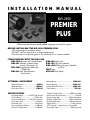
INSTALLATION MANUAL
BW-2500
PREMIER
PLUS
Please read this Manual carefully before attempting to install this system.
BEFORE INSTALLING THE BW-2500 PREMIER PLUS
• DO read through this installation manual.
• DO NOT install the alarm brain in an engine compartment.
• The alarm may arm itself when power is first connected.This is a normal condition.
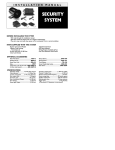
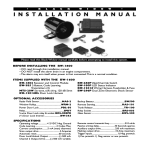
ITEMS SUPPLIED WITH THE BW-2500
BWS-2502 Receiver and Control Module
BWS-385 2-Button, 3-channel, Code
Learning Transmitters (2)
MTS-20W Programmable, Multi-tone,
120 dB Siren
BWS-296 Dual Zone Electronic
Shock Sensor
OPTIONAL ACCESSORIES
Radar Field Sensor.........................................MAS-2
Window Rollup.............................................WRM-2
Power Door Lock........................................PDL-50
SPECIFICATIONS
Operating voltage ...............+12 VDC Neg. Ground
Code Learning ......................................3 Codes Max.
Current consumption .........5 mA (max) disarmed.
Siren output drive ......................................3 Amperes
Automatic reset........................................60 seconds.
Door Lock/Unlock Output ...................(-) 500 mA.
Channel 2 Output Drive ........................(-) 500 mA.
BWS-260 Valet Switch
BWS-180 LED Status Indicator
BWS-12025 Wiring Harness, Fuseholder,
and Fuse
SPDT Relay
BRS-003 Relay Socket
Backup Battery ..................................................BWS-500
Remote Starting.................................................RAS-101
Leather Transmitter Case ...............................BWS-390
Trunk Release ........................................................TR-100
Channel 3 Output Drive..................(-) 500 mA, variable.
Remote control transmit freq.............................310 mHz.
Passive arming delay ............................30 Seconds approx.
Auxiliary output drive..........................250 mA maximum.
Flashing output drive ............................10 Amp maximum.
Trigger inputs..............................................1) Neg. pnswtch.
1) Pos. pnswtch. 1) Neg. sensor or aux. pnswtch.
Dome light output.....................................500 mA ground.
-1INSTALLATION INSTRUCTIONS
IMPORTANT: Make all wiring connections to the vehicle before connecting the main
14-pin and auxiliary 2-pin connector harnesses to the receiver and
control module.
1. Before mounting the BWS-2502 Receiver and Control Module, you must set the PROGRAMMING DIPSWITCHES for the kind of operation the customer wants.
These are the switch settings available; Standard (Default) settings are in “BOLD” type:
Switch #1 Door Lock and Unlock Pulse Time: ON = 3/4 seconds. OFF = 3 seconds.
Switch #2 Door Lock and Unlock with ignition: ON = YES. OFF = NO.
Switch #3 Door Locking with Passive Arming: ON = YES. OFF = NO.
Switch #4 Passive or Active Arming: ON = Passive Arming. OFF = Active Arming.
2. Mount the Receiver and Control Module in a secure area, away from vehicle computers and heating/air conditioning ducts.The location should be convenient for your installation, but well hidden from thieves.Try to mount the unit
as far away from metal objects as possible.This will increase the range of its Remote Control Transmitter.
3. Route the wires of the harnesses to areas in which the different accessories will be mounted .You may
need to extend some wires. DO NOT plug the two wiring harnesses into the Receiver and Control
Module until all connections have been completed.
When running the harness wires through the vehicle, be careful to run them where they CANNOT be DAMAGED or SHORTED to GROUND or other WIRING. Keep them away from ALL MOVING PARTS of the vehicle
or where HIGH HEAT can damage their insulation.Always protect the harness wires where they pass through
holes in metal panels by using RUBBER GROMMETS.
4. Mount the MTS-20W Siren under the vehicle’s hood. Mount it away from heat sources such as radiators,
exhaust manifolds, and turbochargers. Mount it in an area where it will not be in the way for mechanics, and so
that it cannot be easily reached from below the vehicle. Mount it so that its opening points down to prevent it
from collecting water, snow, or ice. Connect its BLACK wire to a good clean GROUND point, and its RED wire to
the ORANGE wire of the main harness.
Siren has 6 tones. You can program from one to six tones by removing rubber grommet on back of unit and
removing or adding jumper contacts.
5. Mount the BWS-296 Shock Sensor Somewhere inside the vehicle such as under the dash, strapped to the
steering column, or under a seat.. Do Not Mount The Sensor Under The Hood!
Connect its BLACK wire to a good, clean GROUND point, its RED wire to a source of CONSTANT +12vdc, and
its BLUE wire to the BLUE wire of the main harness, the GRAY wire to the GRAY wire , the WHITE wire to the
VIOLET wire all from the main harness.
6. Mount the BWS-180 LED Status Indicator in an easily seen location such as the center of the dash or the
inside top edge of the driver’s or passenger’s door. Connect its RED wire to a source of CONSTANT +12vdc, and
its BLACK wire to the RED/BLACK wire of the main harness.
7. Install the BWS-260 Valet/Override Switch in a hidden location that is easily reached by the driver.
Remember that the code learning and valet/override sequence require using this switch in conjunction with the
ignition switch, so it should be hidden, but convenient to use when needed.
8. Mount the BRS-003 Relay Socket and SPDT Relay in a location where it is hidden from potential thieves.
Find the vehicle’s STARTER wire and cut it in half. Connect the colored wires of the Relay Socket as follows:
BLACK
= To STARTER wires on Starter side.
YELLOW = To STARTER wires on Switch side.
GRAY
= GRAY wire of the main harness.
9. Mount and connect any optional function modules included in the installation, following the mounting
and wiring directions supplied with them.
-210. Complete the general wiring of the main harness by connecting...
A. The RED wire to a source of CONSTANT +12vdc. IMPORTANT: Remove the 15 amp fuse from the harness before connection.
B. The BLACK wire to a good chassis GROUND point.
C. The WHITE wire for POSITIVE pinswitches.
or... The BLUE/WHITE wire for NEGATIVE pinswitches.
(NOTE: If your installation requires BOTH inputs, they can both be used on the same installation)
D. The GREEN wire to a source of TRUE IGNITION.
E. The WHITE/YELLOW Dome Light Wire to the vehicle’s Dome Light Circuit. See the Dome Light
Circuit Diagram on Page 5. YOU MUST USE A RELAY FOR THIS CONNECTION.
F. The WHITE/ORANGE wire to the vehicle’s PARKING LIGHT circuit. See the Parking Light Circuit
Diagram on Page 5.
ON VEHICLE’S WITH ELECTRIC DOOR LOCKS:
G. The GREEN/BLACK wire to the vehicle’s door LOCK circuit, using the correct circuit from the
Power Door Lock Wiring Diagrams on Page 5.
H. The YELLOW wire to the vehicle’s door UNLOCK circuit, using the correct circuit from the Power
Door Lock Wiring Diagrams on Page 5.
11. If the Second or Third Channel functions are to be used, connect...
A.The BROWN wire to control the Second Channel device. Suggested uses are for Electric Trunk Release
or Remote Engine Starter.This output will deliver a 1 second NEGATIVE pulse output of 250mA when
ever button 2 is pressed continuously for 3 seconds. See the sample Trunk Release Diagram on Page 5.
YOU MUST USE A RELAY FOR THIS CONNECTION.
B. The WHITE/RED wire to control the third channel device. Suggested uses are for window roll-Up/Down or
External Light control. Negative output when BOTH Buttons are pressed simultaneously.The ouput will continue for as long as the buttons are held down.
YOU MUST USE A RELAY FOR THIS CONNECTION.
CAUTION: Before continuing to the next step, make sure all wiring connections have been properly made.
12. Adjust the Electronic Shock Sensor to the desired sensitivity before continuing with the alarm checkout.
A.Turn the adjustment screw until the unit’s LED reacts to your slapping various parts of the vehicle’s body.
B.Turn CLOCKWISE for more sensitivity, COUNTER-CLOCKWISE for less.
C. DO NOT overadjust the sensor or false alarms may result.
13. Connect the Main 14 Pin Wiring Harness (and 2 Pin Wiring Harness) to the BW-2502 Receiver and
Control Module.
14. To Power-up and enter Transmitter Code Learning, please follow these instructions:
A. Install the 15 amp fuse in the RED wire of the main wiring harness.The unit will power-up in an armed state,
the siren may or may not sound.
B. Before proceeding, you must have the main unit learn the transmitters code.To do this follow this procedure:
1.Turn the ignition switch ON/OFF 3 times. leave ignition ON the 3rd time.The SIREN will chirp once and
the Door Locks (if connected) will LOCK.
2.Within 5 SECONDS, press and HOLD the Valet Switch for 5 seconds, the SIREN will Chirp 3 Times and
the LED will turn SOLID. The System is now in Code Learning Mode.
3. Press Button #1 of either transmitter for Car #1 operation, the system will respond with either 1 or 2
Siren Chirps.The system has now learned the transmitters code. For a two car operation, follow the steps
B1 and B2 for the second vehicle using button #2 of transmitter.
4.Turn OFF the ignition switch.The system is now ready to be tested.
C. Arm the system and test all input triggers and output devices, escpecially the Starter Interrupt Relay.You
should not be able to start the engine while the alarm is armed or sounding.
D. Once all testing is complete, secure all loose wiring and/or components and reassemble the vehicle.
-3-
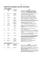
CONNECTOR PIN NUMBERS AND WIRE COLOR CODES
14-PIN HARNESS
#
COLOR
FUNCTION
1)
Red
+12 VDC
2)
Wht/Org
3)
Orange
Parking
Light (+)
Siren (+)
4)
Grn/Blk
5)
Yellow
6)
Gray
7)
8)
Red/Blk
Wht/Yel
9)
Blue
(–) Trip
10)
Violet
Valet (–)
11)
Green
Ignition
12)
Black
Ground
13)
White
14)
Blu/Wht
Positive
Door (+)
Negative
Door (–)
Door
Lock (–)
Door
Unlock (–)
Starter
Interrupt (–)
LED (–)
Dome
Light (–)
NOTES
Main Power. Connect this wire to the POSITIVE
terminal of the vehicle’s battery, with the supplied
fuse installed at the BATTERY END of this wire.
See the wiring diagram for the proper connection of
this wire. For negative output see Page 5.
Connect this wire to the RED wire of the Siren.
Output is +12 volts when the alarm is triggered.
Negative output pulse to door LOCK circuit. See
door lock wiring diagrams on Page 5 for connections.
Negative output pulse to door UNLOCK circuit.
See door lock wiring diagrams on Page 5 for connections.
Negative output to the Starter Interrupt relay.
See Wiring diagram for connections.
Connect to the BLACK wire of the BWS-180 LED.
Negative output to interior light circuits whenever alarm is disarmed. See wiring diagram on Page 5 for
connections.
Negative trip input for connection to an external
shock or motion sensor.
Connect to the VALET switch.This switch is needed for
entering the Code Learning Sequence and Valet/Override
functions.
Connect to a source of TRUE IGNITION, a wire that is
hot in both the RUN and START positions.
Connect this wire to a clean, solid GROUND. Do Not
confuse this wire with the short, black antenna wire.
Do Not Ground The Antenna Wire!
Connect this wire to door pinswitches that are
POSITIVE when the door is open.
Connect this wire to door pinswitches that are
NEGATIVE when the door is open.
2-PIN CONNECTOR (Auxiliary Functions):
#
COLOR
FUNCTION
1)
Brown
Channel 2
2)
Wht/Red
Channel 3
NOTES
Negative output when Button #2 of the transmitter is
pressed for 3 seconds. See the diagram on Page 5.
Negative output when BOTH Buttons are pressed simultaneously. The output will continue for as long as the
buttons are held down.
(Hint:When engaging this output it is best to press button
#2 first, hold it, then press button #1.This will avoid accidentally arming or disarming the system)
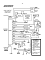
-4TROUBLESHOOTING
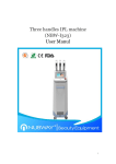
WIRING DIAGRAM
TRUNK
RELEASE,
REMOTE START
2nd/3rd
Channel
Molex
Ignition +12V MUST NOT
DROP OUT during
starting of vehicle.
VARIABLE
OUTPUT
GROUND
RED
BATTERY
12V FLASHING
LIGHT OUTPUT
(10 AMPS)
SEE PAGE 5
BROWN
FUSE
WHITE/RED
SIREN
BLACK
STARTER
INTERRUPT RELAY
RED
GRAY
FUSE
WHITE/ORANGE
30 87a
ORANGE
YELLOW
NEGATIVE DOOR
UNLOCK OUTPUT
GRAY
RECEIVER
MODULE
HARNESS
RED/BLACK
DOME LIGHT
OUTPUT
SEE PAGE 5
WHITE/YELLOW
BLUE
RED
{
SEE
PAGE 5
BLACK
GREEN
X
TO STARTER
+12 VDC
IGNITION
SWITCH
IGNITION
WIRE
VALET
SWITCH
VIOLET
D1A
DIODE
CUT
LED
BLACK
87
85
YELLOW
NEGATIVE DOOR
LOCK OUTPUT
BLACK
GREEN/BLACK
TO BATTERY
GROUND
BLACK
WHITE
DIP SWITCH
PROGRAMS:
POS.
DOOR
SWITCH
BLUE/WHITE
BLACK
BLUE
GROUND
GROUND
DOOR
SWITCH
+12VDC
1 2 3 4
TO VIOLET
WIRE ON
HARNESS
DIP SWITCH
(SEE BOXED
INFORMATION)
WHITE
GRAY
RED
BLACK
ANTENNA
TO GRAY
WIRE ON
HARNESS
12 VDC
2 STAGE
SHOCK
SENSOR
(1) Selects .75 or
3 seconds for door
lock/unlock pulse.
(2) Selects ignition
lock/unlock feature
(3) Selects passive/active
lock.
(4) Selects passive/active
arming.
See programming specifics
on page 1, Section 1.
-5-
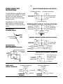
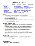
POWER DOOR LOCK
INSTRUCTIONS:
POSITIVE TRIGGER DOOR LOCK CIRCUIT:
TO DOOR LOCK RELAY
The BW-2500 comes equipped to handle
ground door lock installations.The Yellow
and Green wires from the Receiver
Module are ready to tap into grounding
door lock systems.
The following instructions require two
SPDT Relays, not included in the BW2500.These Relays must be ordered separately.
FOR POSITIVE
PARKING LIGHTS
WHITE/ORANGE
TO DOOR UNLOCK RELAY
LOCK
87
GRN/BK WIRE
FROM ALARM
86
87a
87a
85
86
YELLOW WIRE
FROM ALARM
85
30
30
12 V FUSED CONSTANT
REVERSE POLARITY (DIRECTLY TO AD-ON ACTUATORS):
GROUND
GRN/BK WIRE
FROM ALARM
86
87
87a
85
GROUND
YELLOW WIRE
FROM ALARM
87a
85
86
30
30
12 V FUSED
CONSTANT
VEHICLE
PARKING
LIGHT
WIRE
REVERSE POLARITY USING FACTORY SYSTEMS:
LOCK
GREEN WIRE
FROM ALARM
87
86
87a
87
87a
85
87a
SWITCH
LOCK
30
XCUTX
12 V FUSED
CONSTANT
ACTUATOR
XCUTX
UNLOCK
TO VEHICLE
PARKING LIGHT
CIRCUIT
YELLOW WIRE
FROM ALARM
85
86
30
FOR NEGATIVE
PARKING LIGHTS
(MOST JAPANESE VEHICLES)
WHITE/
ORANGE
86
TRUNK RELEASE CIRCUIT DIAGRAM:
OUT TO TRUNK 12V
85
2nd CHANNEL
AUXILIARY
(BROWN WIRE)
30
87
87a
86
85
30
If the power trunk release requires a positive pulse to operate,
use this circuit.
12V POSITIVE
DOME LIGHT
CIRCUIT DIAGRAM:
TO NEGATIVE DOME LIGHT
PINSWITCH
WHITE/
YELLOW
86
87
87a
85
12V POSITIVE
TO POSITIVE DOME LIGHT
PINSWITCH
WHITE/
YELLOW
87
87a
85
30
30
NEGATIVE
TRIGGER
86
GROUND
POSITIVE
TRIGGER
12V POSITIVE
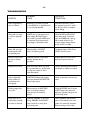
-6TROUBLESHOOTING
PROBABLE
CAUSE
SUGGESTED
CORRECTION
Unit is triggered any
time it is armed.
BLUE wire is shorted to ground
or the BWS-296 or optional sensor
is not correctly adjusted.
Disconnect the wire to see if
the symptom stops. If so, check
the wire for shorts or readjust
sensor fittings.
Alarm will not rearm
or will not passively
arm.
WHITE wire is connected to positive voltage, BLU/WHT wire is
connected to ground, GREEN wire
is connected to permanent positive voltage, or pinswitch is bad.
Check WHITE and BLU/WHT
wires with doors closed and
open, and GREEN wire with ignition switch off and on, for
correct voltage changes. Repair
and/or rewire as needed.
Alarm will arm from
transmitter but will
not passively arm.
Dipswitch #4 is off.VIOLET
wire is shorted to ground.
Set dipswitch #4 to ON. Check
VIOLET wire for shorts.
Remote Control does
not arm or disarm
alarm.
Defective Remote Control. Bad
battery. Antenna wire is
grounded.
Replace Remote Control or its
battery. Un-ground antenna.
Valet does not work.
Wire from Valet switch to ground
is not connected to a good ground
or wire from switch to unit is
open. Bad switch.
Test for switched ground at alarm
unit. Repair or replace as needed.
Interior lights flash
when the alarm is
armed, disarmed.
and tripped.
WHT/ORG Parking Light output
has been switched with WHT/YEL
Dome Light output.
Switch connections on these two
wires.
Flashing output does
not work.
Bad connection on WHT/ORG
wire or the drive polarity is
wrong for the circuit being
driven.
Check WHT/ORG wire. Connect
a SPDT Relay to this wire and
apply the opposite polarity to the
circuit being driven.
Door locks do not
lock/unlock correctly,
or action is reversed.
Defective GRN/BLK or YELLOW
wiring. GRN/BLK and YELLOW
wires reversed, or wrong door
lock wiring used.
Check GRN/BLK and YELLOW
wires. Check vehicle’s door lock
system for method of operation.
Reverse wiring to door relays.
SYMPTOM
LIMITED LIFETIME WARRANTY
The Black Widow Division of DLC, Inc. warrants to the original purchaser that the vehicle alarm system purchased will be free from defects in workmanship.
If it is determined that a defect exists, at our option, we will repair defective parts or
replace the system. If product is defective within one (1) year from date of purchase, item
will be repaired or replaced at no cost to original purchaser. If product is defective after
one (1) year from date of purchase, ship defective unit prepaid to Black Widow Division,
DLC, Inc. along with $20.00 U.S. ($30.00 Canadian) cashier’s check or money order to
cover cost of handling.
Proof of purchase by the original owner must accompany warranty request
before service is rendered.
This warranty covers normal use. It does not cover damage from alteration, misuse,
abuse, accident, improper installation or maintenance.Warranty does not cover transmitter batteries or cases.This warranty gives you specific legal rights and you may have rights
which vary from state to state. If you have any questions, contact your authorized Black
Widow dealer.
VEHICLE SECURITY SYSTEMS
DLC/U.S.A.
12753 Moore Street
Cerritos, California 90703