1
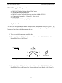
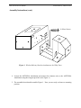
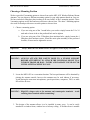
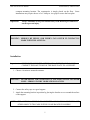
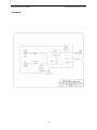
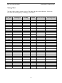
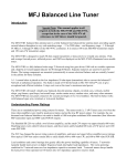
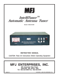
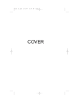
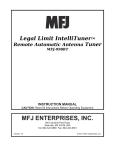
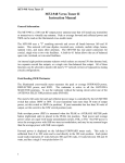
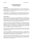
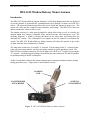
MFJ-1625 Instruction Manual
Window/Balcony Mount Antenna
MFJ-1625 Window/Balcony Mount Antenna
Introduction
The MFJ-1625 Window/Balcony Mount Antenna is a 200 Watt antenna tuner that was designed
to provide portable or permanent HF communications on 80 through 10 meters and VHF on 6
meters. The universal mount design allows the user to install the antenna in many ways. The
mount will easily attach to window frames, balconies, and railings. The MFJ-1625 works well
indoors mounted to a desk or table as well.
The antenna consists of a whip tuner designed for tuning short whips as well as virtually any
random length wire antenna, collapsible whip, universal mount, and counterpoise wire. The
operating frequency is found by turning the knobs on the whip tuner and setting them for
maximum RF current. The counterpoise wire length can also be adjusted for maximum RF
current. The MFJ-1625 Window/Balcony Mount Antenna will allow the operator to get on the
air from locations where antenna size is limited.
The whip tuner section uses a reversible "L" network. The advantage of the “L” network is that
it has only two tuning controls, and only one tuning solution for given impedance match. The
MFJ-1625 has rear panel connectors for coaxial input and a “Hi-Z/Lo-Z” switch for reversing the
“L” network. An internal input-isolating current balun provides isolation of DC and RF grounds
for optimum tuning of the RF counterpoise.
An RF Current Meter indicates the summed antenna and counterpoise antenna currents, making
tuning particularly easy. Simply tune for maximum RF current.
LOADING
COIL
COUNTERPOISE
ATTACHMENT
ANTENNA
ATTACHMENT
Figure 1: MFJ-1625 Window/Balcony Mount Antenna
1
MFJ-1625 Instruction Manual
Window/Balcony Mount Antenna
MFJ-1625 Supplied Components
•
•
•
•
•
•
MFJ-1623 Window/Balcony Mount Whip Tuner
Window/Balcony Mount Bracket
MFJ-63 Loading Coil for 40-80 meter operation with the MFJ-1956
Counterpoise Assembly (6, 14, and 26 ft. long wires)
Safety Rope
MFJ-1956 12 ft. Telescoping Whip Antenna
Assembly Instructions
The MFJ-1625 Window/Balcony Mount Antenna will be disassembled when you receive it. All
you need is a small screwdriver to assemble the unit and begin operating. The supplied
components listed above should accompany the unit.
1. Take the supplied components out of the box.
2. Take out the 4 silver Phillips head screws in the back of the MFJ-1625 Window/Balcony
Mount Whip Tuner. (See Figure 2)
HIGH-Z LOW-Z
4
SILVER
SCREWS
1
1
2
3
4
TRANSMITTER
Figure 2: Rear Panel of MFJ-1625 Window/Balcony Whip Tuner
3. Using the 4 silver Phillips head screws, bolt the back of the MFJ-1625 Window/Balcony
Mount Whip Tuner to the front of the Window/Balcony Mount Bracket. (See Figure 3)
2
MFJ-1625 Instruction Manual
Window/Balcony Mount Antenna
Assembly Instructions (cont.)
4-Silver Screws
1
3
1
4
2
Figure 3: Window/Balcony Bracket Attachment to the Whip Tuner
4. Loosen the ANTENNA Attachment and connect the Antenna wire to the ANTENNA
Attachment using the wing nut provided. (See Figure 1)
5. The assembled unit should resemble Figure 1. Now you are ready to choose a mounting
position.
3
MFJ-1625 Instruction Manual
Window/Balcony Mount Antenna
Choosing a Mounting Position
We have provided 5 mounting options to choose from on the MFJ-1625 Window/Balcony Mount
Antenna. You can choose a different mounting option for your whip antenna based on your use.
We have included a fiberglass plate insulator to be used with 2 of the 5 mounting options. These
2 mounting options are the best and most efficient to choose from. The other 3 mounting options
also work well and provide more versatile options to choose from.
1. Choose a mounting option.
a. If you are using one of the 3 round holes, you need to simply loosen the 3/8 x 24
stud and re-locate it the to the preferred hole and re-tighten.
b. If you are using one of the 2 fiberglass plate insulator holes, simply loosen the 4
fiberglass plate insulator screws, locate the entire plate assembly to the preferred
location, re-insert and re-tighten the screws.
Important:
Always make sure the mount screws are tight or severe injury can occur.
WARNING: ALWAYS ATTACH THE SAFETY ROPE TO A STABLE SUPPORT
BEFORE ATTEMPTING TO ATTACH THE UNIVERSAL MOUNT TO A
WINDOW FRAME OR RAIL. INJURY AND DAMAGE COULD OCCUR
IF THE ANTENNA WERE TO FALL.
2. Locate the MFJ-1625 in a convenient location. The best performance will be obtained by
placing the antenna outside, however the antenna may be used indoors if necessary.
Avoid placing the tuner near microphones, speech processors, computers, TNC's or other
RF sensitive devices.
WARNING: High RF voltages exist at the antenna and counterpoise terminals. Avoid
touching these terminals while transmitting!
3. The design of the antenna allows it to be installed in many ways. It can be easily
attached to a window frame, window box or balcony railing. A Wooden fence is another
4
MFJ-1625 Instruction Manual
Window/Balcony Mount Antenna
common mounting location. The counterpoise is simply placed on the floor. Some
installations may require the use of a C-clamp or vice-grips to secure the base plate.
Important:
Always remember to keep the antenna away from metal objects and out of
reach to prevent injury.
WARNING: SERIOUS RF BURNS AND INJURY CAN OCCUR IF CONTACT IS
MADE WITH THE ANTENNA.
Installation
Important:
WHILE INSTALLING THE ANTENNA TO A WINDOW OR BALCONY
CONNECT THE SAFETY ROP OF THE BASE PLATE TO A SUPPORT.
1. Choose a location to mount the antenna.
WARNING: NEVER MOUNT THE ANTENNA IN A LOCATION CLOSE TO POWER
LINES. SERIOUS INJURY OR DEATH MAY OCCUR.
2. Connect the safety rope to a good support.
3. Attach the mounting bracket in position by placing the bracket over or around the surface
of the support.
NOTE:
THE ANTENNA SHOULD BE ORIENTED AWAY FROM WINDOWS AND
OTHER OBJECTS THAT ARE WITHIN CLOSE RANGE IF POSSIBLE.
5
MFJ-1625 Instruction Manual
Window/Balcony Mount Antenna
4. Tighten the screws on the rear of the base plate against the surface of the support. The
screws should be tightened in equal increments to keep the force on the spacer plate
proportioned.
5. Loosen the Counterpoise Attachment.
6. Insert the end of the counterpoise wire
7. Tighten to secure the counterpoise.
8. Connect your transceiver’s output to the SO-239 (UHF female) connector labeled
TRANSMITTER on the back of the tuner.
9. Decide which mount placement will be used on the mounting bracket according to your
situation. There are five placements available. (See Choosing a Mounting Position
Section)
10. Connect the MFJ-63 Loading Coil Assembly and the MFJ-1956 12 ft. telescopic whip
antenna to the 3/8x24 stud on the top of the mounting bracket and extend to its full
length.
Using the MFJ-1625
CAUTION:
Never Change The Antenna or Inductor Selector Switch Position While
Transmitting! Never Apply More Than 200 Watts To The MFJ-1625.
Preset the controls on the MFJ-1625 as follows:
• ANTENNA to maximum inductance - Position "A"
• MATCHING to minimum capacitance – Position “10”
• NORM/+C switch to NORM
• COUNTERPOISE to minimum inductance – Position “L”
• Hi-Z/Lo-Z switch (back of unit) to Lo-Z
• SENSITIVITY control fully clockwise (maximum sensitivity)
• LOADING COIL tap on turn 0
Most modern solid-state transceivers do not require tuning and loading adjustments. If the
transceiver has a built in antenna tuner, be sure it is turned off or disabled. If your transmitter
has an adjustable output circuit, it must be properly tuned to a 50-ohm load at the operating
frequency before adjusting the tuner. This should be done with a dummy load.
6
MFJ-1625 Instruction Manual
Window/Balcony Mount Antenna
Tuning Procedure
WARNING: Never transmit while changing the INDUCTOR SELECTOR.
1. First, tune for maximum receiver noise as follows:
•
•
•
While listening to your desired receive frequency, adjust the ANTENNA control for
maximum receiver noise.
Adjust the MATCHING control for maximum receiver noise.
Adjust the COUNTERPOISE control for maximum receiver noise.
Note: If no noise peak is evident, try adding extra capacitance with the
NORM/+C switch. Then reverse the HI-Z/LO-Z switch and re-try with both
positions of the NORM/+C switch.
2. For 80-40 meter operation, the loading coil may need to be adjusted.
•
Begin by placing the tap on turn 0, which is the turn closest to the antenna. This will
short the entire coil. The tap should only be in contact with one coil at a time.
•
Moving the tap down or increasing the number of turns increases the electrical length
of the loading coil. This adds inductance to the whip antenna making it more useful
on 80-40 meters.
3. Apply just enough power on CW (or AM/FM/RTTY) to obtain a noticeable deflection on
the RF CURRENT meter.
4. Carefully adjust the ANTENNA, MATCHING and COUNTERPOISE controls for
maximum RF current as follows.
•
•
•
Adjust the MATCHING capacitor for maximum RF current.
Adjust the COUNTERPOISE inductor for maximum RF current.
Try plus or minus a position or two on the ANTENNA inductor, along with tuning
the MATCHING capacitor to see if higher RF current is achievable.
Note: These controls interact. Go back and forth between these adjustments as required until
maximum RF current is obtained.
5. The transmitter power may now be increased up to a maximum of 200 Watts. Make sure
you reduce the RF SENSITIVITY control as necessary to keep from pinning the RF
Current meter.
In Case of Difficulty
If this tuner fails to tune, please double check all connections and follow the tuning procedure
again.
The power rating of this tuner is 200 Watts on 80-10 meters. If this tuner arcs at the rated power
levels, please double-check all connections and follow the tuning procedure again.
If you are still unsuccessful, please read the following ANTENNA HINTS text.
7
MFJ-1625 Instruction Manual
Window/Balcony Mount Antenna
Grounding Hints
To minimize RFI, antennas should be kept away from other wiring as much as possible. Also,
the antenna should be adequately insulated to prevent arcing or accidental contact if placed near
other objects.
For safety, it is always best to use both dc and RF grounds. A DC ground may not be practical in
some portable locations, however.
It is always important to have a good RF ground, provided by the counterpoise, when using any
whip or long-wire antenna. This is because the MFJ-1625 tuner needs something to "push"
against in order to force current into the antenna. If a good RF ground is not available, RF will
usually find its way back into the power line (RFI), transmitter audio circuits (RF feedback), or
the operator (RF burns).
Water pipes provide good dc and ac safety grounds, but they are often inadequate for RF
grounding because they are long single conductors. RF grounds require large "spread out"
surfaces with direct multiple connections to the equipment ground point. Water pipes, heating
ducts, or multiple ground rods may work (especially if they are all connected together with
jumper wires), but the best RF grounds are radial systems or multi-wire counterpoises.
Antenna Hints
WARNING:
For operator safety, a good earth ground should be installed and connected
to the case of the MFJ-1625. Make certain the safety ground connects to
the same terminal that connects to the transmitter and other station
accessories. A binding post labeled "COUNTERPOISE" is provided for
counterpoise or other RF ground connection(s). This post will not provide a
safety ground.
Matching Problems
Most matching problems occur when the antenna system presents extremely high impedance to
the tuner. This occurs when the antenna is approximately a half-wavelength long at the
frequency at which you are trying to tune.
8
MFJ-1625 Instruction Manual
Window/Balcony Mount Antenna
MFJ-1625 Artificial Ground
The MFJ-1625 contains a series L-circuit that is used to tune the RF ground system (either a
counterpoise or a ground wire). Maximum ground current will flow through the MFJ-1625 RF
current meter when the COUNTERPOISE switch is properly set.
Installation of a Suitable Counterpoise / Artificial Ground
The MFJ-1625 includes a counterpoise set of wires that will work well from 80-10 meters. It is
important to keep the last few feet of the counterpoise wires as far as possible (two feet
minimum) from each other and other near-by conductors.
You can also build your own counterpoise system if you desire. A RF counterpoise system can
be as simple as a single wire a quarter wave long or less, or as complicated as several wires cut
for different bands. Always insulate counterpoise wires and keep them from accidentally
contacting animals, people, RF sensitive devices and wiring. For best performance, try to
position the counterpoise wires in a straight line if possible.
A counterpoise wire must be well insulated. For best performance, several wires a quarterwavelength long on different frequencies should be connected together at the COUNTERPOISE
post of the MFJ-1625.
When counterpoise wires are located indoors, they can be laid on a floor under a carpet, placed
in an attic, or stapled to a basement ceiling. If you place the counterpoise under the carpet or
where someone may contact it, be sure to use well insulated wire and multiple counterpoise
wires. Insulate the far end of the counterpoise wire(s) with electrical tape to prevent accidental
contact.
When counterpoise wires are used outdoors, only place them high enough to walk under. Use
multiple wires spaced a few feet apart (at minimum).
DANGER:
Touching counterpoise and/or antenna wires while transmitting can cause an
RF burn. The wire must be well insulated and the end properly insulated.
There are cases very little deflection of the RF current meter can be seen. However, even though
the meter may not indicate much RF current change while adjusting the COUNTERPOISE
control, even the slightest RF current peak indicates that the artificial ground is helping.
9
MFJ-1625 Instruction Manual
Window/Balcony Mount Antenna
Tuning Out Reactance of Long Ground Leads
If the station ground has a long lead, you can connect it to the COUNTERPOISE binding post of
the MFJ-1625. Connect the station ground bus and accessories to the GROUND post. Do not
reverse these wires. Follow the same procedure for maximizing RF Current described in the
tuning procedure.
WARNING:
This unit does NOT provide a dc or ac safety ground through the
COUNTERPOISE terminal. A separate wire from the station ground bus
to an electrical or earth ground must be used.
TVI and RFI Hints
It is possible for RF to flow down power cables into the house wiring. This may cause TVI,
Stereo, VCR or other RFI problems. As a precaution, a ferrite core can be clamped around
power leads. The MFJ-701 RFI-FREE CHOKE KIT makes it easy to eliminate common RFI
problems.
Technical Assistance:
If you have any problem with this unit first check the appropriate section of this manual. If the
manual does not reference your problem or your problem is not solved by reading the manual,
you may call MFJ Technical Service at 662-323-0549 or the MFJ Factory at 662-323-5869.
You will be best helped if you have your unit, manual and all information on your station handy
so you can answer any questions the technicians may ask.
You can also send questions by mail to MFJ Enterprises, Inc., 300 Industrial Park Road,
Starkville, MS 39759; by Facsimile (FAX) to 662-323-6551; or by email to
[email protected]. Send a complete description of your problem, an explanation of
exactly how you are using your unit, and a complete description of your station.
10
MFJ-1625 Instruction Manual
Window/Balcony Mount Antenna
Schematic
11
MFJ-1625 Instruction Manual
Window/Balcony Mount Antenna
Tuning Chart
You may wish to remove or make a copy of this page and place it near the tuner. Insert your
own values for each frequency according to your station.
Freq MHz
1.8
Counterpoise
Matching
Antenna
3.5
3.75
4.0
7.15
10.1
14.2
18.1
21.2
24.9
28.5
12
Hi/Lo Z switch
Extra cap switch