1
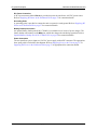
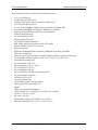
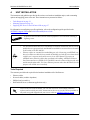
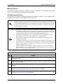
NetVanta 6240/6250 Series
IP Business Gateways
Hardware Installation Guide
61700202G1-34B
August 2013
Trademarks
NetVanta 6240/6250 Series HIG
Trademarks
Any brand names and product names included in this manual are trademarks, registered trademarks, or
trade names of their respective holders.
To the Holder of the Manual
The contents of this manual are current as of the date of publication. ADTRAN reserves the right to change
the contents without prior notice.
In no event will ADTRAN be liable for any special, incidental, or consequential damages or for
commercial losses even if ADTRAN has been advised thereof as a result of issue of this publication.
Software Licensing Agreement
Each ADTRAN product contains a single license for ADTRAN-supplied software. Pursuant to the
Licensing Agreement, you may: (a) use the software on the purchased ADTRAN device only and (b) keep
a copy of the software for backup purposes. This Agreement covers all software installed on the system, as
well as any software available on the ADTRAN website. In addition, certain ADTRAN systems may
contain additional conditions for obtaining software upgrades.
Third-Party Software
The software included in the NetVanta 6250 contains copyrighted software that is licensed under the GNU
General Public License (GPL). For a list of third-party software and their licenses, go to
http://www.adtran.com/software/EULA. You can obtain the complete corresponding source code of such
software components from ADTRAN for a period of three years after our last shipment of this product by
sending a money order or check for $5 to:
ADTRAN, Inc, P.O. Box 933638, Atlanta, GA 31193-3638
Please write GPL Source for product NetVanta 6250 in the memo line of your payment.
This offer is valid to anyone in receipt of this information.
Changes or modifications to this unit not expressly approved by the party responsible for
compliance could void the user’s authority to operate the equipment.
901 Explorer Boulevard
P.O. Box 140000
Huntsville, AL 35814-4000
Phone: (256) 963-8000
Copyright © 2013 ADTRAN, Inc.
All Rights Reserved.
Printed in U.S.A.
2
Copyright © 2013 ADTRAN, Inc.
61700202G1-34B
NetVanta 6240/6250 Series HIG
Conventions
Conventions
Notes provide additional useful information.
Cautions signify information that could prevent service interruption or damage to the
equipment.
Warnings provide information that could prevent injury or endangerment to human
life.
61700202G1-34B
Copyright © 2013 ADTRAN, Inc.
3
Safety Instructions
NetVanta 6240/6250 Series HIG
Safety Instructions
When using your telephone equipment, please follow these basic safety precautions to reduce the risk of
fire, electrical shock, or personal injury:
1. Do not use this product near water, such as a bathtub, wash bowl, kitchen sink, laundry tub, in a
wet basement, or near a swimming pool.
2. Avoid using a telephone (other than a cordless type) during an electrical storm. There is a remote
risk of shock from lightning.
3. Do not use the telephone to report a gas leak in the vicinity of the leak.
4. Use only the power cord, power supply, and batteries indicated in the manual. Do not dispose of
batteries in a fire. They may explode. Check with local codes for special disposal instructions.
5. The socket-outlet shall be installed near the equipment and shall be easily accessible.
If any of the following conditions occur, unplug the product from the electrical outlet and replace the part
or contact your qualified service personnel:
1. The power cable, extension cable, or plug is damaged.
2. An object has fallen into the product.
3. The product has been exposed to water.
4. The product has been dropped or damaged.
5. The product does not operate correctly when you follow the operating instructions.
These units contain no user-serviceable parts. They should only be serviced by qualified
service personnel.
Additional safety guidelines, such as Waste Electrical and Electronic Equipment (WEEE),
are given in the document NetVanta Safety and Regulatory Information available online at
http://supportforums.adtran.com.
Save These Important Safety Instructions
4
Copyright © 2013 ADTRAN, Inc.
61700202G1-34B
NetVanta 6240/6250 Series HIG
FCC-Required Information
FCC-Required Information
FCC regulations require that the following information be provided in this manual:
1. This equipment complies with Part 68 of Federal Communications Commission (FCC) rules and
requirements adopted by America’s Carriers Telecommunications Association (ACTA). Each
registered interface has a label that contains, among other information, a product identifier in the
format US:AAAEQ##TXXXX. If requested, provide this information to the telephone company.
2. If this equipment causes harm to the telephone network, the telephone company may temporarily
discontinue service. If possible, advance notification is given; otherwise, notification is given as
soon as possible. The telephone company will advise the customer of the right to file a complaint
with the FCC.
3. The telephone company may make changes in its facilities, equipment, operations, or procedures
that could affect the proper operation of this equipment. Advance notification and the opportunity
to maintain uninterrupted service are given.
4. If experiencing difficulty with this equipment, please contact ADTRAN for repair and warranty
information. The telephone company may require this equipment to be disconnected from the
network until the problem is corrected, or it is certain the equipment is not malfunctioning.
5. This unit contains no user-serviceable parts.
6. This equipment is designed to connect to the telephone network or premises wiring using an
FCC-compatible modular jack, which is compliant with Part 68 and requirements adopted by
ACTA.
7. The following information may be required when applying to the local telephone company for
leased line facilities:
Part Number
Registration
Number
Service Type
US: HDCIT03B1700204G1
REN/SOC
FIC
USOC
1.544 Mbps - SF
1.544 Mbps - SF and B8ZS
1.544 Mbps - ESF
1.544 Mbps - ESF and B8ZS
N/A/6.0N
04DU9-BN
04DU9-DN
04DU9-1KN
04DU9-1SN
RJ-48C
NetVanta 6240
with Optional
FXO Ports
Analog Loop Start/Ground Start
0.3B/9.0F
02LS2
02GS2
RJ-11C
NetVanta 6250
T1 Products
1.544 Mbps - SF
1.544 Mbps - SF and B8ZS
1.544 Mbps - ESF
1.544 Mbps - ESF and B8ZS
N/A/6.0N
04DU9-BN
04DU9-DN
04DU9-1KN
04DU9-1SN
RJ-48C
Analog Loop Start/Ground Start
0.0B/9.0F
02LS2
02GS2
RJ-11C
NetVanta 6240
T1 Products
US: HDCIS00B1700254F2
NetVanta 6250
with Optional
FXO Port
8. The ringer equivalency number (REN) is useful in determining the quantity of devices you may
connect to your telephone line and still have all of those devices ring when your number is called.
In most areas, the sum of the RENs of all devices should not exceed five. To be certain of the
number of devices you may connect to your line as determined by the REN, call your telephone
company to determine the maximum REN for your calling area.
9. This equipment may not be used on coin service provided by the telephone company. Connection
to party lines is subject to state tariffs. Contact your state public utility commission or corporation
commission for information.
61700202G1-34B
Copyright © 2013 ADTRAN, Inc.
5
FCC Radio Frequency Interference Statement
NetVanta 6240/6250 Series HIG
FCC Radio Frequency Interference Statement
This equipment has been tested and found to comply with the limits for a Class B digital device, pursuant
to Part 15 of the FCC rules. These limits are designed to provide reasonable protection against harmful
interference when the equipment is operated in a commercial environment. This equipment generates,
uses, and can radiate radio frequency energy and, if not installed and used in accordance with the
instruction manual, may cause harmful interference to radio frequencies. Operation of this equipment in a
residential area is likely to cause harmful interference in which case the user will be required to correct the
interference at his own expense.
Industry Canada Compliance Information
Notice: The Industry Canada label applied to the product (identified by the Industry Canada logo or the
“IC:” in front of the certification/registration number) signifies that the Industry Canada technical
specifications were met.
Notice: The REN for this terminal equipment is supplied in the documentation or on the product labeling/
markings. The REN assigned to each terminal device indicates the maximum number of terminals that can
be connected to a telephone interface. The termination on an interface may consist of any combination of
devices subject only to the requirement that the sum of the RENs of all the devices should not exceed five
(5).
Canadian Emissions Requirements
This digital apparatus does not exceed the Class B limits for radio noise emissions from digital apparatus
as set out in the interference-causing equipment standard entitled “Digital Apparatus,” ICES-003 of the
Department of Communications.
Cet appareil numérique respecte les limites de bruits radioelectriques applicables aux appareils numériques
de Class A prescrites dans la norme sur le materiel brouilleur: “Appareils Numériques,” NMB-003 edictee
par le ministre des Communications.
Toll Fraud Liability
Be advised that certain security risks are inherent in the use of any telecommunications or networking
equipment, including but not limited to, toll fraud, Denial of Service (DoS) attacks, loss or theft of data,
and the unauthorized or illegal use of said equipment. ADTRAN OFFERS NO WARRANTIES, EITHER
EXPRESSED OR IMPLIED, REGARDING THE PREVENTION, DETECTION, OR DETERRENCE
OF TOLL FRAUD, NETWORKING ATTACKS, OR UNAUTHORIZED, ILLEGAL, OR IMPROPER
USE OF ADTRAN EQUIPMENT OR SOFTWARE. THEREFORE, ADTRAN IS NOT LIABLE FOR
ANY LOSSES OR DAMAGES RESULTING FROM SUCH FRAUD, ATTACK, OR IMPROPER USE,
INCLUDING, BUT NOT LIMITED TO, HUMAN AND DATA PRIVACY, INTELLECTUAL
PROPERTY, MATERIAL ASSETS, FINANCIAL RESOURCES, LABOR AND LEGAL COSTS.
Ultimately, the responsibility for securing your telecommunication and networking equipment rests with
you, and you are encouraged to review documentation regarding available security measures, their
configuration and implementation, and to test such features as is necessary for your network.
Service and Warranty
For information on the service and warranty of ADTRAN products, visit the Support section of the
ADTRAN website at http://www.adtran.com.
6
Copyright © 2013 ADTRAN, Inc.
61700202G1-34B
Table of Contents
Introduction . . . . . . . . . . . . . . . . . . . . . . . . . . . . . . . . . . . . . . . . . . . . . . . . . . . . . . . . . . . . . . . . . . . . . . . 13
Physical Description . . . . . . . . . . . . . . . . . . . . . . . . . . . . . . . . . . . . . . . . . . . . . . . . . . . . . . . . . . . . . . .
NetVanta 6240 Series . . . . . . . . . . . . . . . . . . . . . . . . . . . . . . . . . . . . . . . . . . . . . . . . . . . . . . . . . . . .
Shipping Contents . . . . . . . . . . . . . . . . . . . . . . . . . . . . . . . . . . . . . . . . . . . . . . . . . . . . . . . . . . . . . . .
Front Panel Design . . . . . . . . . . . . . . . . . . . . . . . . . . . . . . . . . . . . . . . . . . . . . . . . . . . . . . . . . . . . . .
Rear Panel Design . . . . . . . . . . . . . . . . . . . . . . . . . . . . . . . . . . . . . . . . . . . . . . . . . . . . . . . . . . . . . . .
NetVanta 6250 Series . . . . . . . . . . . . . . . . . . . . . . . . . . . . . . . . . . . . . . . . . . . . . . . . . . . . . . . . . . . .
Shipping Contents . . . . . . . . . . . . . . . . . . . . . . . . . . . . . . . . . . . . . . . . . . . . . . . . . . . . . . . . . . . . . . .
Front Panel Design . . . . . . . . . . . . . . . . . . . . . . . . . . . . . . . . . . . . . . . . . . . . . . . . . . . . . . . . . . . . . .
Rear Panel Design . . . . . . . . . . . . . . . . . . . . . . . . . . . . . . . . . . . . . . . . . . . . . . . . . . . . . . . . . . . . . . .
14
14
14
14
15
17
17
17
19
Product Specifications . . . . . . . . . . . . . . . . . . . . . . . . . . . . . . . . . . . . . . . . . . . . . . . . . . . . . . . . . . . . . . 21
Unit Installation . . . . . . . . . . . . . . . . . . . . . . . . . . . . . . . . . . . . . . . . . . . . . . . . . . . . . . . . . . . . . . . . . . . . 23
Tools Required . . . . . . . . . . . . . . . . . . . . . . . . . . . . . . . . . . . . . . . . . . . . . . . . . . . . . . . . . . . . . . . . . . 23
Mounting Options . . . . . . . . . . . . . . . . . . . . . . . . . . . . . . . . . . . . . . . . . . . . . . . . . . . . . . . . . . . . . . . . 24
Supplying Power to the Unit . . . . . . . . . . . . . . . . . . . . . . . . . . . . . . . . . . . . . . . . . . . . . . . . . . . . . . . . 27
Supplying DC Power to the NetVanta 6250 . . . . . . . . . . . . . . . . . . . . . . . . . . . . . . . . . . . . . . . . . . . . 27
Optional Battery Backup Unit (P/N 1175044L1/L2) . . . . . . . . . . . . . . . . . . . . . . . . . . . . . . . . . . . . . . 29
Appendix A.
61700202G1-34B
Connector Pin Definitions. . . . . . . . . . . . . . . . . . . . . . . . . . . . . . . . . . . . . . . . . . . . . . . 33
Copyright © 2013 ADTRAN, Inc.
7
Table of Contents
8
NetVanta 6240/6250 Series HIG
Copyright © 2013 ADTRAN, Inc.
61700202G1-34B
List of Figures
Figure 1.
Figure 2.
Figure 3.
Figure 4.
Figure 5.
Figure 6.
Figure 7.
NetVanta 6240 Front Panel Layout . . . . . . . . . . . . . . . . . . . . . . . . . . . . . . . . . . . . . . . . . . . .
NetVanta 6240 Rear Panel Layout . . . . . . . . . . . . . . . . . . . . . . . . . . . . . . . . . . . . . . . . . . . . .
NetVanta 6250 Front Panel Layout . . . . . . . . . . . . . . . . . . . . . . . . . . . . . . . . . . . . . . . . . . . .
NetVanta 6250 Rear Panel Layout . . . . . . . . . . . . . . . . . . . . . . . . . . . . . . . . . . . . . . . . . . . . .
Wallmount Installation . . . . . . . . . . . . . . . . . . . . . . . . . . . . . . . . . . . . . . . . . . . . . . . . . . . . . .
Supplying DC Power and Grounding the NetVanta 6250 . . . . . . . . . . . . . . . . . . . . . . . . . . .
Wall Mounting the BBU . . . . . . . . . . . . . . . . . . . . . . . . . . . . . . . . . . . . . . . . . . . . . . . . . . . . .
61700202G1-34B
Copyright © 2013 ADTRAN, Inc.
14
15
17
19
26
28
30
9
List of Figures
10
NetVanta 6240/6250 Series HIG
Copyright © 2013 ADTRAN, Inc.
61700202G1-34B
List of Tables
Table 1.
Table 2.
Table 3.
Table A-1.
Table A-2.
Table A-3.
Table A-4.
Table A-5.
Table A-6.
Table A-7.
NetVanta 6240 Front Panel LEDs . . . . . . . . . . . . . . . . . . . . . . . . . . . . . . . . . . . . . . . . . . . . . 15
NetVanta 6250 Front Panel LEDs . . . . . . . . . . . . . . . . . . . . . . . . . . . . . . . . . . . . . . . . . . . . . 18
BBU Specifications. . . . . . . . . . . . . . . . . . . . . . . . . . . . . . . . . . . . . . . . . . . . . . . . . . . . . . . . . 31
VOICE Connector Pinouts (NetVanta 6240) . . . . . . . . . . . . . . . . . . . . . . . . . . . . . . . . . . . . . 33
VOICE Connector Pinouts (NetVanta 6250) . . . . . . . . . . . . . . . . . . . . . . . . . . . . . . . . . . . . . 34
FXO Connector Pinouts . . . . . . . . . . . . . . . . . . . . . . . . . . . . . . . . . . . . . . . . . . . . . . . . . . . . . 35
T1 Port Pinouts . . . . . . . . . . . . . . . . . . . . . . . . . . . . . . . . . . . . . . . . . . . . . . . . . . . . . . . . . . . 35
10/100Base-T Ethernet Port Pinouts . . . . . . . . . . . . . . . . . . . . . . . . . . . . . . . . . . . . . . . . . . . 35
1000Base-T Gigabit Ethernet Port Pinouts . . . . . . . . . . . . . . . . . . . . . . . . . . . . . . . . . . . . . . 35
CRAFT Port Pinouts. . . . . . . . . . . . . . . . . . . . . . . . . . . . . . . . . . . . . . . . . . . . . . . . . . . . . . . . 36
61700202G1-34B
Copyright © 2013 ADTRAN, Inc.
11
List of Tables
12
NetVanta 624050 Series HIG
Copyright © 2013 ADTRAN, Inc.
61700202G1-34B
1.
INTRODUCTION
This hardware installation guide describes the NetVanta 6240/6250 Series units’ physical characteristics, lists
their features and specifications, introduces basic functionality, and provides installation instructions.
•
•
•
Physical Description on page 14
Product Specifications on page 21
Unit Installation on page 23
For additional information on shipping contents, mounting options, and power the unit, refer to the following
sections:
•
•
•
•
•
Shipping Contents on page 14
Mounting Options on page 24
Supplying Power to the Unit on page 27
Supplying DC Power to the NetVanta 6250 on page 27
Optional Battery Backup Unit (P/N 1175044L1/L2) on page 29
For information on NetVanta 6240/6250 configuration for a specific application, refer to the configuration
guides provided on the ADTRAN Support Community. For details on the command line interface (CLI), refer to
the AOS Command Reference Guide. All other related documents are also available online at
http://supportforums.adtran.com.
61700202G1-34B
Copyright © 2013 ADTRAN, Inc.
13
Physical Description
2.
NetVanta 6240/6250 Series HIG
PHYSICAL DESCRIPTION
NetVanta 6240 Series
The NetVanta 6240 Series is a multiservice Internet Protocol (IP) business gateway designed for use in
integrated voice and data service offerings to small-to-medium sized businesses worldwide. This product line is
a high-bandwidth business gateway designed to allow carriers to deliver up to 60 channels of Voice over IP
(VoIP) to their customers. The NetVanta 6240 Series units run ADTRAN Operating System (AOS), and are
managed through an EIA-232 port (DB-9) located on the rear panel, Telnet session, or web-based graphical user
interface (GUI). The NetVanta 6240 is RoHS compliant (telecommunications exemption).
There are several models in the NetVanta 6240 Series that can provide various combinations up to 24 FXS
interfaces, up to 10 FXO interfaces, and up to 60 channels of VoIP. All NetVanta 6240 Series models include
four modular T1 wide area network (WAN) interfaces, two 10/100Base-T Ethernet ports, an integrated router,
stateful inspection firewall, and transparent Session Initiation Protocol (SIP) proxy. The NetVanta 6240 Series
comes equipped with an AC power supply and an onboard battery charger for use with an ADTRAN battery
backup unit that can keep the unit running with all interfaces active should the AC power fail.
Shipping Contents
Each NetVanta 6240 Series units are shipped in their own cardboard shipping carton. Open each carton
carefully, and avoid deep penetration into the carton with sharp objects.
After unpacking the unit, inspect it for possible shipping damage. If the equipment has been damaged in transit,
immediately file a claim with the carrier and contact ADTRAN Customer Service (refer to the Support page on
the ADTRAN website at http://www.adtran.com/support).
Shipments of the NetVanta 6240 Series include the following items:
•
•
•
•
NetVanta 6240 Series base unit
A detachable power cable with a grounded, three-prong plug
Two standard mounting brackets and four screws
Quick start guide
Front Panel Design
The NetVanta 6240 front panel is shown below.
S
1
2
3
4
1
2
E
U
AT
ST
T
T
T
IC
VO
NE
NE
NE
T
N
N
NE
LA
LA
NetVanta 6240
Figure 1. NetVanta 6240 Front Panel Layout
14
Copyright © 2013 ADTRAN, Inc.
61700202G1-34B
NetVanta 6240/6250 Series HIG
Physical Description
Front Panel Features
Status LEDs
The status LEDs are located on the right side of the front panel. The STATUS LED indicates the unit’s
status. The VOICE LED indicates the status of the voice ports. The NET 1 through NET 4 LEDs reflect
the status of the network interfaces. The LAN 1 and LAN 2 LEDs reflect the status of the local area
networks (LANs). Table 1 below describes the front panel LEDs.
Table 1. NetVanta 6240 Front Panel LEDs
LED
STATUS
VOICE
NET 1 through
NET 4
LAN 1/LAN 2
Color
Indication
Off
Unit is not receiving power.
Green (flashing)
On power up, the STATUS LED flashes rapidly for five
seconds, during which time the user may escape to boot
mode from the CONSOLE port.
Green (solid)
Power is on and the unit is functioning normally.
Amber (solid)
Power has failed and the unit is in battery backup mode.
Red
Power is on, but the self-test failed.
Off
All ports are inactive or administratively disabled.
Green (flashing)
At least one port is ringing.
Green (solid)
At least one port is off-hook.
Amber (solid)
Port is in test mode.
Red
Alarm or fault condition is occurring on the port interface.
Off
All ports are inactive or administratively disabled.
Green (solid)
Port is functioning normally.
Amber (solid)
Port is in test mode.
Red
Alarm or fault condition is occurring on the port interface.
Off
LAN is administratively disabled or link is down.
Green (solid)
The link is up.
Amber (flashing)
There is activity on the link.
Rear Panel Design
The NetVanta 6240 Series rear panel is shown below.
FXO 0/1
FXO 0/2
NET 1
T1 0/1
NET 2
T1 0/2
NET 3
T1 0/3
NET 4
T1 0/4
PRI/CAS
ETH 0/1
ETH 0/2
10/100
BASE-T
10/100
BASE-T
Figure 2. NetVanta 6240 Rear Panel Layout
61700202G1-34B
Copyright © 2013 ADTRAN, Inc.
15
Physical Description
NetVanta 6240/6250 Series HIG
Rear Panel Interfaces
VOICE Connection
A single 50-pin female amphenol connector, labeled VOICE, provides the interconnect wiring for the
analog FXS/FXO circuits. See Table A-1 on page 33 for voice connector pinouts. The status LED,
labeled VOICE, is located on the front panel.
The number of circuits used (1 through 24) is dependent on the model NetVanta 6240.
FXO interfaces use circuits 17 through 24 depending on the model.
FXO Interfaces
The FXO 0/1 and FXO 0/2 interfaces are RJ-11 connectors and provide analog trunks for local call
routing. See Table A-3 on page 35 for the FXO interface pinouts.
Network Interfaces
The NET 1 T1 0/1 through NET 4 T1 0/4 interfaces are DS1 RJ-48C pin connections. See Table A-4 on
page 35 for the network interface pinouts. The status LEDs, labeled NET 1 through NET 4, are located
on the front panel.
10/100Base-T Ethernet Interfaces
The ETH 0/1 and ETH 0/2 ports are RJ-45 connectors. See Table A-5 on page 35 for the Ethernet
interface pinouts. The status LEDs, labeled LAN 1 and LAN 2, are located on the front panel.
CRAFT Interface
The CRAFT interface is an EIA-232 serial port (DCE), which provides for local management and
configuration (via a DB-9 female connector). See Table A-7 on page 36 for the craft interface
pinouts.
Connection directly to an external modem requires a cross-over cable.
Power Connection
The rear panel has a power input to a 120 VAC power supply with an IEC connector. The appropriate
three-prong cable is included in the shipment. Refer to Supplying Power to the Unit on page 27 for
connection details.
Battery Backup Connection
An optional battery backup unit (P/N 1175044L1/L2) is available for use in case of power outages.
The battery backup unit connects to the BATT port, which also charges the unit during operation. Refer
to Optional Battery Backup Unit (P/N 1175044L1/L2) on page 29 for connection details.
16
Copyright © 2013 ADTRAN, Inc.
61700202G1-34B
NetVanta 6240/6250 Series HIG
Physical Description
NetVanta 6250 Series
The NetVanta 6250 Series is a multiservice Internet Protocol (IP) business gateway designed for use in
integrated voice and data service offerings to small-to-medium sized businesses worldwide. This product line is
a high-bandwidth business gateway designed to allow carriers to deliver up to 72 channels of Voice over IP
(VoIP) to their customers. The NetVanta 6250 Series units run ADTRAN Operating System (AOS), and are
managed through an EIA-232 port (DB-9) located on the rear panel, Telnet session, or web-based graphical user
interface (GUI). The NetVanta 6250 is RoHS compliant.
There are several models in the NetVanta 6250 Series that can provide various combinations up to 24 FXS
interfaces, up to 9 FXO interfaces, and up to 60 channels of VoIP. All NetVanta 6250 Series models include four
modular T1 wide area network (WAN) interfaces, four routed 10/100Base-T Ethernet ports, one routed
10/100/1000Base-T Ethernet port (both copper and fiber), one Universal Serial Bus (USB) port, an integrated
router, stateful inspection firewall, and transparent Session Initiation Protocol (SIP) proxy. The NetVanta 6250
Series comes equipped with an AC power supply and an onboard battery charger for use with an ADTRAN
battery backup unit that can keep the unit running with all interfaces active should the AC power fail. The
NetVanta 6250 also comes equipped with a -48 VDC input for DC powering.
ADTRAN does not recommend using the optional battery backup unit when the
NetVanta 6250 is being powered by a DC source.
Shipping Contents
Each NetVanta 6250 Series units are shipped in their own cardboard shipping carton. Open each carton
carefully, and avoid deep penetration into the carton with sharp objects.
After unpacking the unit, inspect it for possible shipping damage. If the equipment has been damaged in transit,
immediately file a claim with the carrier and contact ADTRAN Customer Service (refer to the Support page on
the ADTRAN website at http://www.adtran.com/support).
Shipments of the NetVanta 6250 Series include the following items:
•
•
•
•
•
NetVanta 6250 Series base unit
A detachable power cable with a grounded, three-prong plug
Two universal 19/23-inch rack mounting brackets and four screws
Two position terminal block for connection to DC power source
Quick start guide
Front Panel Design
The NetVanta 6250 front panel is shown below.
VOICE
STATUS
GIG 1
USB
1
2
T1
3
4
1
2
ETH
3
4
NetVanta 6250
Figure 3. NetVanta 6250 Front Panel Layout
61700202G1-34B
Copyright © 2013 ADTRAN, Inc.
17
Physical Description
NetVanta 6240/6250 Series HIG
Front Panel Features
Status LEDs
The status LEDs are located on the left side of the front panel. The VOICE LED indicates the status of
the voice ports. The STATUS LED indicates the unit’s status. The GIG 1 LED indicates the status of
the Gigabit Ethernet port (both fiber and copper). The USB LED indicates the status of the USB port.
The T1 1 through 4 LEDs reflect the status of the network interfaces. The ETH 1 through 4 LEDs
reflect the status of the local area networks (LANs). Table 2 below describes the front panel LEDs.
Table 2. NetVanta 6250 Front Panel LEDs
LED
STATUS
VOICE
USB
GIG 1
T1 1 through T1 4
ETH 1 through ETH
4
18
Color
Indication
Off
Unit is not receiving power.
Green (flashing)
On power up, the STATUS LED flashes rapidly for five
seconds, during which time the user may escape to boot
mode from the CONSOLE port.
Green (solid)
Power is on and the unit is functioning normally.
Amber (solid)
Power has failed and the unit is in battery backup mode.
Red
Power is on, but the self-test failed.
Off
All ports are inactive or administratively disabled.
Green (flashing)
At least one port is ringing.
Green (solid)
At least one port is off-hook.
Amber (solid)
Port is in test mode.
Red
Alarm or fault condition is occurring on the port interface.
Off
Interface is shut down or not connected.
Green (solid)
A supported device is connected.
Amber (flashing)
There is activity on the link.
Off
Port is inactive or administratively disabled.
Green (solid)
The link is up.
Amber (flashing)
There is activity on the link.
Off
All ports are inactive or administratively disabled.
Green (solid)
Data T1 is up with Layer 2, PRI T1 is up with D-channel,
RBS is up with Layer 1.
Green (flashing)
Data T1 is up with Layer 2 down, PRI T1 is up with
D-channel down.
Amber (solid)
T1 is in test mode.
Red
Alarm or fault condition is occurring on the port interface.
Off
LAN is administratively disabled or link is down.
Green (solid)
The link is up.
Amber (flashing)
There is activity on the link.
Copyright © 2013 ADTRAN, Inc.
61700202G1-34B
NetVanta 6240/6250 Series HIG
Physical Description
Rear Panel Design
The NetVanta 6250 Series rear panel is shown below.
T1 0/1
T1 0/3
ETH 0/1
ETH 0/3
FXO
0/0
VOICE
AC INPUT
GIG 0/1
T1 0/2
T1 0/4
ETH 0/2
ETH 0/4
USB
10/100/1000
BASE-T
CRAFT
RTN -48V
DC IN
BBU
Figure 4. NetVanta 6250 Rear Panel Layout
Rear Panel Interfaces
VOICE Connection
A single 50-pin female amphenol connector, labeled VOICE, provides the interconnect wiring for the
analog FXS/FXO circuits. See Table A-2 on page 34 for voice connector pinouts. The status LED,
labeled VOICE, is located on the front panel.
The number of circuits used (1 through 24) is dependent on the model NetVanta 6250.
FXO interfaces use circuits 17 through 24 depending on the model.
FXO Interface
The FXO 0/0 interface is an RJ-11 connector and provides analog trunks for local call routing. See
Table A-3 on page 35 for the FXO interface pinouts.
Network Interfaces
The T1 0/1 through T1 0/4 interfaces are DS1 RJ-48C pin connections. See Table A-4 on page 35 for
the network interface pinouts. The status LEDs, labeled T1 1 through 4, are located on the front panel.
10/100Base-T Ethernet Interfaces
The ETH 0/1 through ETH 0/4 ports are RJ-45 connectors. See Table A-5 on page 35 for the Ethernet
interface pinouts. The status LEDs, labeled ETH 1 through 4, are located on the front panel.
10/100/1000Base-T Ethernet Interfaces
The GIG 0/1 ports consist of one RJ-45 and one small form-factor pluggable (SFP) slot for
connectivity over fiber. (Use either the RJ-45 connector or the SFP slot. The fiber slot has precedence.)
See Table A-6 on page 35 for the Ethernet interface pinouts. The status LED, labeled GIG 1, is located
on the front panel.
USB Interface (Future Release)
The USB interface is Type A USB host connector and is provided for use with 3G/4G modems or flash
drives. The status LED, labeled USB, is located on the front panel. A USB power switch is used to
limit the current drawn by a device connected to the USB port.
CRAFT Interface
The CRAFT interface is an EIA-232 serial port (DCE), which provides for local management and
configuration (via a DB-9 female connector). See Table A-7 on page 36 for the craft interface
pinouts.
Connection directly to an external modem requires a cross-over cable.
61700202G1-34B
Copyright © 2013 ADTRAN, Inc.
19
Physical Description
NetVanta 6240/6250 Series HIG
DC Power Connection
A DC input connector, labeled DC IN, is provided to power the unit from a -48 VDC power source.
Refer to Supplying DC Power to the NetVanta 6250 on page 27 for connection details.
Grounding Point
A grounding point is provided to connect the unit to a protective earth ground. Refer to Supplying DC
Power to the NetVanta 6250 on page 27 for connection details.
Battery Backup Connection
An optional battery backup unit (P/N 1175044L1) is available for use in case of power outages. The
battery backup unit connects to the BBU port, which also charges the unit during operation. Refer to
Optional Battery Backup Unit (P/N 1175044L1/L2) on page 29 for connection details.
Power Connection
The rear panel has a power input to a 120 VAC power supply with an IEC connector. The appropriate
three-prong cable is included in the shipment. Refer to Supplying Power to the Unit on page 27 or
Supplying DC Power to the NetVanta 6250 on page 27 as appropriated for connection details.
20
Copyright © 2013 ADTRAN, Inc.
61700202G1-34B
NetVanta 6240/6250 Series HIG
3.
Product Specifications
PRODUCT SPECIFICATIONS
The NetVanta 6240 Series products have the following features:
•
•
•
•
•
•
•
•
•
•
•
•
•
•
•
•
•
•
•
•
•
•
•
•
•
•
•
•
•
•
•
•
•
8, 16, or 24 foreign exchange station (FXS) ports
16 FXS ports and 8 foreign exchange office (FXO) ports
Optional 1 onboard FXO (RJ-11) interface on the rear panel
4 T1 WAN (RJ-48C) interfaces
4 auto medium dependent interface/medium dependent interface crossover (MDI/MDIX)
10/100Base-T Ethernet ports (RJ-48C)
EIA-232 craft port (DCE) provided for local management
Up to 72 channels of VoIP; simultaneous TDM to IP conversions
Stateful inspection firewall
IPsec VPN (100 tunnels minimum)
Data Encryption Standard (DES), 3DES, and Advanced Encryption Standard (AES) encryption for
IPsec VPN traffic
Quality of service/network address translation/Dynamic Host Configuration Protocol
(QoS/NAT/DHCP) client, server, and relay
Supports SIP trunks
Supports Point-to-Point Protocol (PPP), Multilink PPP, Frame Relay, Multilink Frame Relay, and high
level data link control (HDLC)
Three-way conferencing
Caller ID, call waiting, call transfer, message waiting, distinctive ringing, and star codes
Fax and analog modem compatible (V.29, V.32, V.32bis, V.34, V.90, V.92)
Local station-to-station calls
Up to 60 channels of ITU T.38
Up to 72 channels of G.711 (µ-law)
Up to 72 channels of G.726
Up to 72 channels of G.729
Up to 72 channels of dual tone multi-frequency (DTMF) detection/generation
Up to 72 channels of caller ID
Conforms to ITU G.168
64 ms echo cancellation
200 ms adaptive jitter buffer per channel
User-friendly GUI and a familiar CLI
Simple Network Management Protocol (SNMP)
LEDs for system status information
Chassis dimensions: 1.75-inch H x 16.5-inch W x 10.25-inch D
AC power: 100 to 120 VAC, 60 Hz
Optional battery backup (1175044L1/L2): -48 VDC
Operating temperature: 32°F (0°C) to +122°F (+50°C)
61700202G1-34B
Copyright © 2013 ADTRAN, Inc.
21
Product Specifications
NetVanta 6240/6250 Series HIG
The NetVanta 6250 Series products have the following features:
•
•
•
•
•
•
•
•
•
•
•
•
•
•
•
•
•
•
•
•
•
•
•
•
•
•
•
•
•
•
•
•
•
•
•
•
22
8, 16, or 24 FXS ports
16 FXS ports and 9 FXO ports
1 built-in FXO lifeline on the rear panel (F2 models only)
4 T1 WAN (RJ-48C) interfaces
1 routed 10/100/1000Base-T Ethernet port (copper RJ-45 and fiber SFP)
4 routed auto MDI/MDIX 10/100Base-T Ethernet ports (RJ-48C)
EIA-232 craft port (DCE) provided for local management
USB port (host mode only)
Up to 60 channels of VoIP
Stateful inspection firewall
IPsec VPN (50 tunnels minimum)
DES, 3DES, and AES encryption for IPsec VPN traffic
QoS/NAT/DHCP client, server, and relay
Supports SIP trunks
Supports PPP, Multilink PPP, Frame Relay, Multilink Frame Relay, and HDLC
Three-way conferencing
Caller ID, call waiting, call transfer, message waiting, distinctive ringing, and star codes
Fax and analog modem compatible (V.29, V.32, V.32bis, V.34, V.90, V.92)
Local station-to-station calls
Up to 8 channels of ITU T.38
Up to 60 channels of G.711 (µ-law)
Up to 60 channels of G.726
Up to 60 channels of G.729
Up to 60 channels of DTMF detection/generation
Up to 60 channels of caller ID
Conforms to ITU G.168
64 ms echo cancellation
200 ms adaptive jitter buffer per channel
User-friendly GUI and a familiar CLI
SNMP
LEDs for system status information
Chassis dimensions: 1.72-inch H x 17.2-inch W x 10.5-inch D
AC power: 120 VAC, 60 Hz
DC power: -48 VDC
Optional battery backup (1175044L1/L2): -48 VDC
Operating temperature: 32°F (0°C) to +122°F (+50°C)
Copyright © 2013 ADTRAN, Inc.
61700202G1-34B
NetVanta 6240/6250 Series HIG
4.
Unit Installation
UNIT INSTALLATION
The instructions and guidelines provided in this section cover hardware installation topics, such as mounting
options and supplying power to the unit. These instructions are presented as follows:
•
•
•
Tools Required on page 23
Mounting Options on page 24
Supplying DC Power to the NetVanta 6250 on page 27
For information on configuring a specific application, refer to the configuration guides provided on the
ADTRAN’s Support Forum or the AOS Command Reference Guide.
To prevent electrical shock, do not install equipment in a wet location or during a
lightning storm.
•
The NetVanta 6240/6250 Series is intended to be installed, maintained, and serviced by
qualified service personnel only and should be installed in a restricted access location
as described in UL/IEC 60950-1.
•
Ethernet cables are intended for intrabuilding use only. Connecting an ADTRAN unit
directly to Ethernet cables that run outside the building in which the unit is housed will
void the user's warranty and could create a fire or shock hazard. To connect an
ADTRAN unit to Ethernet cables that run outside the building, ADTRAN's Ethernet
Port Protection Device (EPPD) (P/N 1700502G1) must be connected between the unit
and the outside plant cable. Use of any Ethernet protector other than ADTRAN's for this
purpose will void the user's warranty.
Tools Required
The customer-provided tools required for the hardware installation of the NetVanta are:
•
•
•
•
Ethernet cables
Network cables (module dependent)
Phillips-head screwdriver
Drill and drill bit set (wallmount applications only)
To access the CLI of the NetVanta, you will also need a PC with terminal emulation
software and a console port cable. Instructions on how to access the CLI are available in
the quick start guide shipped with your unit or online at ADTRAN’s Support Forum.
61700202G1-34B
Copyright © 2013 ADTRAN, Inc.
23
Unit Installation
NetVanta 6240/6250 Series HIG
Mounting Options
The unit may be installed in rackmount, wallmount, or tabletop configurations. The following sections provide
step-by-step instructions for rack mounting and wall mounting.
Rack Mounting the NetVanta
The NetVanta is a 1U-high, rack-mountable unit that can be installed into 19-inch or 23-inch equipment racks.
The following steps guide you in mounting the NetVanta into a rack.
ADTRAN recommends 1U (1.75 inches) of separation above and below the
NetVanta 6240/6250 Series unit. This spacing allows the unit to dissipate heat. The design
of the NetVanta 6240/6250 Series uses the chassis to distribute heat generated by the unit’s
internal cards. This design allows the unit to operate without a cooling fan, ensuring the
overall reliability of the unit.
•
•
•
•
•
If installed in a closed or multi-unit rack assembly, the operating ambient temperature
of the rack environment may be greater than room ambient temperature. Therefore,
consideration should be given to installing the equipment in an environment compatible
with the maximum ambient temperature specified by the manufacturer.
Installation of the equipment in a rack should be such that the amount of air flow
required for safe operation of the equipment is not compromised.
Be careful not to compromise the stability of the equipment mounting rack when
installing this product.
Consideration should be given to the connection of the equipment to the supply circuit
and the effect that overloading the circuit might have on overcurrent protection and
supply wiring. Appropriate consideration of equipment nameplate ratings should be
used when addressing this concern.
Reliable grounding of rack-mounted equipment should be maintained. Particular
attention should be given to supply connections other than direct connections to the
branch circuit (e.g., use of power strips).
Instructions for Rack Mounting the NetVanta
Step
Action
1
Attach universal rackmount brackets in the appropriate (either 19-inch or 23-inch) position using
the supplied screws.
2
To allow proper grounding, scrape the paint from the rack around the mounting holes where the
NetVanta will be positioned.
3
Position the NetVanta in a stationary equipment rack allowing 1U space above the unit for
ventilation.
4
Have an assistant hold the unit in position as you install two mounting bolts through the unit’s
brackets and into the equipment rack using a #2 Phillips-head screwdriver.
5
Apply power to the unit (refer to Supplying Power to the Unit on page 27 or Supplying DC Power
to the NetVanta 6250 on page 27 as appropriate).
24
Copyright © 2013 ADTRAN, Inc.
61700202G1-34B
NetVanta 6240/6250 Series HIG
Unit Installation
Wall Mounting the NetVanta
By following these instructions exactly, the NetVanta can be safely mounted on the wall.
•
•
•
To avoid damaging the unit, use only the screws included in the shipment when
attaching mounting ears to the chassis.
When wall mounting the NetVanta, care must be taken not to damage the power cord.
Do not attach the power cord to the building surface or run it through walls, ceilings.
floors, or openings in the building structure.
The socket-outlet must be installed near the equipment and must be easily accessible.
Instructions for Wall Mounting the NetVanta
Step
Action
1
Attach the rack mounting brackets rotated 90 degrees so the rackmount tab (two screw holes)
is parallel with the unit. Reattach the mounting ears to the chassis (see Figure 5 on page 26).
2
Decide on a location for the NetVanta, keeping in mind that the unit needs to be mounted at or
below eye-level so that the LEDs are viewable.
Warning! The NetVanta 6240/6250 can only be wall mounted with the front panel facing to the
right, to the left, or downward (see the example in Figure 5 on page 26). Do not mount with
the LED facing up.
3
Prepare the mounting surface by attaching a board (typically plywood, 3/4-inch to 1-inch thick)
to a wall stud using #6 to #10 (2.5-inch or greater in length) wood screws.
Important! Mounting to a stud ensures stability. Using sheetrock anchors may not provide
sufficient long-term stability.
4
Have an assistant hold the unit in position as you install two #6 to #10 (1-inch or greater in
length) wood screws through the unit’s brackets and into the mounted board (see Figure 5 on
page 26).
5
Proceed to the steps given in Supplying Power to the Unit on page 27 or Supplying DC Power
to the NetVanta 6250 on page 27 (NetVanta 6250 only) as appropriate.
61700202G1-34B
Copyright © 2013 ADTRAN, Inc.
25
Unit Installation
NetVanta 6240/6250 Series HIG
Figure 5. Wallmount Installation
26
Copyright © 2013 ADTRAN, Inc.
61700202G1-34B
NetVanta 6240/6250 Series HIG
Unit Installation
Supplying Power to the Unit
The NetVanta 6240/6250 Series units come equipped with a 120 VAC, 60 Hz power supply for connecting to a
properly grounded power receptacle. (A detachable power cable with a grounded, three-prong plug comes with
the shipment.) To power this unit, connect the power cable to an appropriate AC power source.
•
•
•
•
•
•
In addition to the equipment earthing conductor in the power supply cord, a
supplementary equipment earthing conductor is to be installed between the system and
earth.
The supplemental earthing conductor shall be connected to the equipment using a
number 8 ring terminal and should be fastened to the grounding lug provided on the
rear panel of the equipment. The ring terminal should be installed using the
appropriate crimping tool (AMP P/N 59250 T-EAD Crimping Tool or equivalent).
The supplementary equipment earthing conductor must not be smaller in size than
cross-sectional area of not less than 2.5 mm2, if mechanically protected. The
supplementary equipment earthing conductor is to be connected to the product at the
terminal provided, and connected to earth in a manner that will retain the earth
connection when the power supply cord is unplugged. The connection to earth of the
supplementary earthing conductor must be in compliance with the appropriate rules for
terminating bonding jumpers in Part K of Article 250 of the National Electrical Code,
ANSI/NFPA 70, and Article 10 of Part 1 of the Canadian Electrical Code, Part 1,
C22.1. Termination of the supplementary earthing conductor is permitted to be made
to building steel, to a metal electrical raceway system, or to any earthed item that is
permanently and reliably connected to the electrical service equipment earthed.
Bare, covered, or insulated earthing conductors are acceptable. A covered or insulated
conductor must have a continuous outer finish that is either green, or green with one or
more yellow stripes.
A readily accessible disconnect device, that is suitably approved and rated, shall be
incorporated in the field wiring.
Maximum recommended ambient operating temperature is 50°C.
Supplying DC Power to the NetVanta 6250
The NetVanta 6250 can also be connected to a centralized DC power source via the two-position terminal block
connector (DC IN) located on the rear of the chassis (see Figure 6 on page 28). Power and ground connections
require copper conductors and a ring lug.
ADTRAN does not recommend using the optional battery backup unit when the
NetVanta 6250 is being powered from a DC source.
61700202G1-34B
Copyright © 2013 ADTRAN, Inc.
27
Unit Installation
NetVanta 6240/6250 Series HIG
Instructions for Connecting DC Power Source to the NetVanta 6250
Step
Action
1
Insert the positive terminal of the DC power source into left position of the two-position terminal
block (labeled RTN on the NetVanta 6250). Tighten the screw.
2
Insert the negative terminal of the DC power source into the right position of the two-position
terminal block (labeled -48V on the NetVanta 6250). Tighten the screw.
3
With the power disconnected, insert the terminal block into the receptacle labeled DC IN until it
is firmly seated against the chassis. Tighten the two screws.
4
Connect a ground wire (fitted with a number 8 ring terminal end) to the grounding lug using the
screw provided and the appropriate crimping tool (AMP P/N 59250 T-EAD Crimping Tool or
equivalent). Connect the other end of the ground wire to a protective earth ground. See
Figure 6 below.
5
Supply DC power to the unit.
•
•
•
•
•
•
Power to the NetVanta 6250 system must be from a reliably grounded 48 VDC.
Use only copper conductors when making power connections.
Install unit in accordance with the requirements of NEC NFPA 70.
The branch circuit overcurrent protection shall be a fuse or circuit breaker rated
minimum -48 VDC, maximum 10 A.
A readily accessible disconnect device, that is suitably approved and rated, shall be
incorporated in the field wiring.
Maximum recommended ambient operating temperature is 50°C.
CRAF
T
RTN
AC IN
P
-48V
UT
DC IN
BBU
Figure 6. Supplying DC Power and Grounding the NetVanta 6250
28
Copyright © 2013 ADTRAN, Inc.
61700202G1-34B
NetVanta 6240/6250 Series HIG
Unit Installation
Optional Battery Backup Unit (P/N 1175044L1/L2)
The ADTRAN battery backup unit (BBU) is an optional device designed as a backup DC power supply for
the NetVanta 6240/6250 Series. The BBU connects to the NetVanta 6240/6250 through a 6-foot
charge/discharge, 2-conductor wire with a keyed modular plug (included with the BBU). The 1175044L1
BBU is a low profile wallmount configuration. It can be rack mounted with the appropriate 19-inch or
23-inch rackmount adapter brackets. The 19-inch rackmount adapter bracket part number is
P/N 1175047L1. The 23-inch rackmount adapter bracket part number is P/N 1175048L1.
ADTRAN does not recommend using the optional battery backup unit when the
NetVanta 6250 is being powered from a DC source.
Features of the BBU, P/N 1175044L1, include the following:
•
•
•
•
•
•
No-spill battery design
Compact wallmount or rackmount box
Double BBU rack mounting available
7 AHR battery (up to 8 hours of backup, depending on load)
Modular plug (provides quick and easy installation)
All mounting hardware included
Unpack and Inspect the BBU
After unpacking the BBU unit, inspect it for damage. If damage is noted, file a claim with the carrier; then
contact ADTRAN Customer Service.
Batteries are retained and prewired in the BBU in a specific pattern. Battery position is maintained by foam
spacers press fitted against the housing walls. Removing batteries or disconnecting wires compromises
correct reassembly and should not be attempted.
BBU Safety and EMC Notices
•
Removing the BBU covers could allow batteries to fall out.
•
The BBU should only be used in specified ADTRAN applications.
•
The BBU (P/N 1175044L1) weighs in excess of 30 pounds. Arrange for assistance when
handling the BBU for mounting.
This device complies with Part 15 of the FCC rules. Operation is subject to the following two conditions:
•
•
This device may not cause harmful interference.
This device must accept any interference received, including that which may cause undesired operation.
61700202G1-34B
Copyright © 2013 ADTRAN, Inc.
29
Unit Installation
NetVanta 6240/6250 Series HIG
Wall Mounting the BBU
Figure 7 shows the BBU (P/N 1175044L1) mounting dimensions for the NetVanta 6240/6250 Series.
Figure 7. Wall Mounting the BBU
Install the BBU as follows:
Instructions for Wall Mounting the BBU
Step
Action
1
Decide on a location for the BBU, keeping in mind that the cable plugs must be able to reach
their designated sockets in the NetVanta unit.
2
Prepare the mounting surface by attaching a board (typically plywood, 3/4-inch to 1-inch thick)
to a wall stud using #6 to #10 (2.5-inch or greater in length) wood screws.
Important! Mounting to a stud ensures stability. Using sheetrock anchors may not provide
sufficient long-term stability.
3
Ensuring a plumb measurement, mark where the pilot holes are to be drilled according to the
dimensions given in Figure 7 on page 30.
4
Drill all four pilot holes using a size 1/16-inch drill bit.
5
Screw two #10 x 3/4-inch pan-head screws into the top two previously drilled holes. Let the
head of each screw protrude 1/16 inch from the plywood to engage the keyhole slot.
Do not let the weight of the BBU rest on the two keyhole screws. Maintain support
until the lower two screws are fully inserted.
30
6
With an assistant, lift the BBU and position to engage the screw heads into the top two
keyholes. Allow the unit to slide down until the slot end rests against the screws.
7
Insert the two lower screws through the tabs and tighten securely.
8
Use cable ties as appropriate. The battery connection from the BBU should be directly
connected to the BATT port on the rear of the chassis.
Copyright © 2013 ADTRAN, Inc.
61700202G1-34B
NetVanta 6240/6250 Series HIG
Unit Installation
BBU Maintenance
•
•
•
•
The BBU does not require routine maintenance for normal operation. The life expectancy of the BBU
is 3 to 5 years on standby when used at room temperature.
Excessive heat decreases battery power and life. Extreme low temperature also decreases battery
capacity. Ideal ambient temperature for battery life and capacity is 20°C.
Battery shelf life is extended in cooler temperatures.
To order replacement batteries, reference the following part number: 1975044L1 (12 V replacement
batteries).
ADTRAN is an environmentally friendly company. Therefore, we encourage the proper recycling and
handling of the batteries. Federal and state laws prohibit the improper disposal of all lead acid batteries.
The customer is responsible for the handling of their batteries from the day of purchase through their
ultimate disposal. For more information on battery replacement and recycling, refer to the document
Battery Replacement and Recycling.
BBU Specifications
Table 3 provides BBU specifications.
Table 3. BBU Specifications
Battery
Part Number:
Suppliers:
Batteries:
Voltage:
Backup Time:
Wire Gauge:
311212V02
YUASA and Panasonic
7 AHR per battery
-12 VDC per battery
Up to 8 hours
18 AWG
Environmental
Operating Temperatures:
Preferred:
Charge: -15°C to 50°C
Discharge: -20°C to 60°C
20°C
Physical Dimensions
P/N 1175044L1:
Weight:
17-inch W x 6.5-inch H x 3.5-inch D
30 lb
Your NetVanta unit is now ready to be configured and connected to the network. For information on
configuration for a specific application, refer to the configuration guides provided online on ADTRAN’s
Support Forum For details on the CLI, refer to the AOS Command Reference Guide. All other related documents
are also available online on ADTRAN’s Support Forum.
61700202G1-34B
Copyright © 2013 ADTRAN, Inc.
31
Unit Installation
32
NetVanta 6240/6250 Series HIG
Copyright © 2013 ADTRAN, Inc.
61700202G1-34B
APPENDIX A.
CONNECTOR PIN DEFINITIONS
The following tables provide the pin assignments for the base unit.
Table A-1. VOICE Connector Pinouts (NetVanta 6240)
Pins
50-pin
Amphenol
Connector
1, 26
Circuit 1
FXS 0/1 Ring, Tip
2, 27
Circuit 2
FXS 0/2 Ring, Tip
3, 28
Circuit 3
FXS 0/3 Ring, Tip
4, 29
Circuit 4
FXS 0/4 Ring, Tip
5, 30
Circuit 5
FXS 0/5 Ring, Tip
6, 31
Circuit 6
FXS 0/6 Ring, Tip
7, 32
Circuit 7
FXS 0/7 Ring, Tip
8, 33
Circuit 8
FXS 0/8 Ring, Tip
9, 34
Circuit 9
FXS 0/9 Ring, Tip
10, 35
Circuit 10
FXS 0/10 Ring, Tip
11, 36
Circuit 11
FXS 0/11 Ring, Tip
12, 37
Circuit 12
FXS 0/12 Ring, Tip
13, 38
Circuit 13
FXS 0/13 Ring, Tip
14, 39
Circuit 14
FXS 0/14 Ring, Tip
15, 40
Circuit 15
FXS 0/15 Ring, Tip
16, 41
Circuit 16
FXS 0/16 Ring, Tip
17, 42
Circuit 17
FXS 0/17 Ring, Tip or FXO 0/3 Ring, Tip
18, 43
Circuit 18
FXS 0/18 Ring, Tip or FXO 0/4 Ring, Tip
19, 44
Circuit 19
FXS 0/19 Ring, Tip or FXO 0/5 Ring, Tip
20, 45
Circuit 20
FXS 0/20 Ring, Tip or FXO 0/6 Ring, Tip
21, 46
Circuit 21
FXS 0/21 Ring, Tip or FXO 0/7 Ring, Tip
22, 47
Circuit 22
FXS 0/22 Ring, Tip or FXO 0/8 Ring, Tip
23, 48
Circuit 23
FXS 0/23 Ring, Tip or FXO 0/9 Ring, Tip
24, 49
Circuit 24
FXS 0/24 Ring, Tip or FXO 0/10 Ring, Tip
25, 50
—
61700202G1-34B
Description
Unused
Copyright © 2013 ADTRAN, Inc.
33
Appendix A
NetVanta 6240/6250 Series HIG
Table A-2. VOICE Connector Pinouts (NetVanta 6250)
34
Pins
50-pin
Amphenol
Connector
1, 26
Circuit 1
FXS 0/1 Ring, Tip
2, 27
Circuit 2
FXS 0/2 Ring, Tip
3, 28
Circuit 3
FXS 0/3 Ring, Tip
4, 29
Circuit 4
FXS 0/4 Ring, Tip
5, 30
Circuit 5
FXS 0/5 Ring, Tip
6, 31
Circuit 6
FXS 0/6 Ring, Tip
7, 32
Circuit 7
FXS 0/7 Ring, Tip
8, 33
Circuit 8
FXS 0/8 Ring, Tip
9, 34
Circuit 9
FXS 0/9 Ring, Tip
10, 35
Circuit 10
FXS 0/10 Ring, Tip
11, 36
Circuit 11
FXS 0/11 Ring, Tip
12, 37
Circuit 12
FXS 0/12 Ring, Tip
13, 38
Circuit 13
FXS 0/13 Ring, Tip
14, 39
Circuit 14
FXS 0/14 Ring, Tip
15, 40
Circuit 15
FXS 0/15 Ring, Tip
16, 41
Circuit 16
FXS 0/16 Ring, Tip
17, 42
Circuit 17
FXS 0/17 Ring, Tip or FXO 0/1 Ring, Tip
18, 43
Circuit 18
FXS 0/18 Ring, Tip or FXO 0/2 Ring, Tip
19, 44
Circuit 19
FXS 0/19 Ring, Tip or FXO 0/3 Ring, Tip
20, 45
Circuit 20
FXS 0/20 Ring, Tip or FXO 0/4 Ring, Tip
21, 46
Circuit 21
FXS 0/21 Ring, Tip or FXO 0/5 Ring, Tip
22, 47
Circuit 22
FXS 0/22 Ring, Tip or FXO 0/6 Ring, Tip
23, 48
Circuit 23
FXS 0/23 Ring, Tip or FXO 0/7 Ring, Tip
24, 49
Circuit 24
FXS 0/24 Ring, Tip or FXO 0/8 Ring, Tip
25, 50
FXO 0/0
FXO 0/0
Description
Copyright © 2013 ADTRAN, Inc.
61700202G1-34B
NetVanta 6240/6250 Series HIG
Appendix A
Table A-3. FXO Connector Pinouts
Pin
Name
Description
1, 2
—
3
Ring
4
Tip
Tip lead of the 2-wire interface
5, 6
—
Unused
Unused
Ring lead of the 2-wire interface
Table A-4. T1 Port Pinouts
Pin
Name
Description
1
RX
Receive data from the network–Ring
2
RX
Receive data from the network–Tip
3
—
Unused
4
TX
Transmit data toward the network–Ring
5
TX
Transmit data toward the network–Tip
6-8
—
Unused
Table A-5. 10/100Base-T Ethernet Port Pinouts
Pin
Name
Description
1
TX+
Transmit Positive
2
TX-
Transmit Negative
3
RX+
Receive Positive
4, 5
—
6
RX-
7, 8
—
Unused
Receive Negative
Unused
Table A-6. 1000Base-T Gigabit Ethernet Port Pinouts
Pin
Name
Description
1
TRD0+
Transmit/Receive Positive
2
TRD0-
Transmit/Receive Negative
3
TRD1+
Transmit/Receive Positive
4
TRD2+
Transmit/Receive Positive
5
TRD2-
Transmit/Receive Negative
6
TRD1-
Transmit/Receive Negative
7
TRD3+
Transmit/Receive Positive
8
TRD3-
Transmit/Receive Negative
61700202G1-34B
Copyright © 2013 ADTRAN, Inc.
35
Appendix A
NetVanta 6240/6250 Series HIG
Table A-7. CRAFT Port Pinouts
36
Pin
Name
Description
1
DCD
Data Carrier Detect (output)
2
TXD
Receive Data (output)
3
RXD
Transmit Data (input)
4
DTR
Data Terminal Ready (input)
5
GND
Signal Ground
6
DSR
Data Set Ready (output)
7
RTS
Request to Send (input)
8
CTS
Clear to Send (output)
9
—
Unused
Copyright © 2013 ADTRAN, Inc.
61700202G1-34B