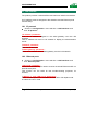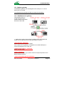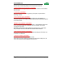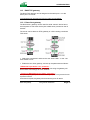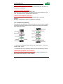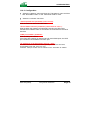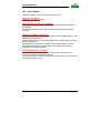
1
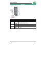
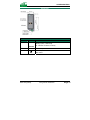
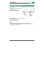
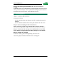
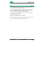
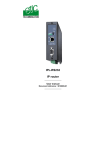
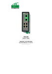
IPRS-1201 IPRS-1220 IPRS-1230
Serial to IP gateway
USB to IP gateway
_________________
User manual
Document reference : 9018409-01
_________________
The IPRS gateway is designed and manufactured by
ETIC TELECOM
13 Chemin du vieux chêne
38240 MEYLAN
FRANCE
TEL : + 33 4-76-04-20-00
FAX : + 33 4-76-04-20-01
E-mail : [email protected]
web : www.etictelecom.com
Page 2
User guide ref. 9018409-01
IPRS serial gateway
CONTENT
OVERVIEW
1
PRODUCTS IDENTIFICATION.................................................................................... 5
2
PRODUCT OVERVIEW............................................................................................... 6
3
TECHNICAL DATA...................................................................................................... 7
INSTALLATION
1
PRODUCT DESCRIPTION ......................................................................................... 9
2
VENTILATION............................................................................................................ 14
3
SUPPLY VOLTAGE................................................................................................... 14
4
ETHERNET PORTS................................................................................................... 14
5
RS232 INTERFACE ................................................................................................... 14
6
RS485 INTERFACE ................................................................................................... 15
7
DIGITAL INPUT & OUTPUT CONNECTION............................................................. 16
SETUP
1
SET UP STEPS.......................................................................................................... 17
2
OVERVIEW ................................................................................................................ 17
3
FIRST CONFIGURATION.......................................................................................... 18
4
MODIFYING THE CONFIGURATION........................................................................ 20
5
REBOOTING THE IPRS GATEWAY AFTER PARAMETERS CHANGES............... 21
6
RECOVERING THE FACTORY LAN IP ADDRESS ................................................. 22
7
RECOVERING THE FACTORY CONFIGURATION ................................................ 22
8
RESTRICTING ACCESS TO THE ADMINISTRATION SERVER ............................. 22
9
RECOVERING A FREE ACCESS TO THE ADMINISTRATION SERVER ............... 23
IPRS serial gateway
User guide ref. 9018409-01
Page 3
CONTENT
… SETUP
10
11
12
13
LAN INTERFACE...................................................................................................... 24
10.1
IP protocol .................................................................................................... 24
10.2
Ethernet ports............................................................................................... 24
SERIAL TO IP GATEWAY......................................................................................... 25
11.1
COM port data rate....................................................................................... 26
11.2
Modbus gateway .......................................................................................... 27
11.3
RAW TCP gateway ....................................................................................... 31
11.4
RAW UDP gateway....................................................................................... 34
11.5
“Multicast” gateway..................................................................................... 36
USB TO IP GATEWAY .............................................................................................. 39
12.1
Principles ...................................................................................................... 39
12.2
Configuration................................................................................................ 40
ALARMS .................................................................................................................... 41
13.1
SNMP............................................................................................................. 41
13.2
Digital output alarm ..................................................................................... 41
13.3
E-mail alarm.................................................................................................. 41
DIAGNOSTIC AND MAINTENANCE
1
DIAGNOSTIC ............................................................................................................. 43
2
SAVING THE PARAMETERS TO A FILE ................................................................. 44
3
UPDATING THE FIRMWARE.................................................................................... 45
Appendix 1 : html server overview
Appendix 2 : VPN technology
Page 4
User guide ref. 9018409-01
IPRS serial gateway
OVERVIEW
1
Products identification
IPRS-
Serial Raw TCP client or server
Serial UDP
Serial UDP multicast
Serial gateway Modbus TCP client or server
Serial gateway Telnet
Serial Unitelway
USB PPP to IP
RJ45 10 / 100 BT
USB host
RS232
RS485
SNMP
Digital input for alarm emails
HTML setup
IO Viewer : optional dynamic data html server
1201
•
2
1
•
1
•
•
1220
•
•
•
•
•
2
1
1
•
1
•
•
1230
•
•
•
•
•
2
2
•
1
•
•
The sign • means the function is provided
The sign - means the function is not provided
IPRS serial gateway
User guide ref. 9018409-01
Page 5
OVERVIEW
2
Product overview
The IPRS-1220 provides one RS232 port and one RS485 port (2 wires).
The IPRS-1230 provides two RS232 port.
The IPRS-1220 or IPRS-1230 gateway can be
Raw TCP client or server
RAW UDP
RAW UDP multicast
Telnet server
Modbus TCP client or server
Unitelway
The IPRS-1201 provides one USB port. The IPRS-120 gateway is a PPP
client over the USB interface.
Page 6
User guide ref. 9018409-01
IPRS serial gateway
OVERVIEW
3
Technical data
Car
General characteristics
Dimensions
137 x 48 x 116 mm (h, l, p)
Electrical safety
EN 60950- UL 1950
ESD : EN61000-4-2 : Discharge 6 KV
RF field : EN61000-4-3 : 10V/m < 2 GHz
EMC
Fast transient : EN61000-4-4
Surge voltage : EN61000-4-5 : 4KV line / earth
RoHS
2002/95/CE (RoHS)
Supply voltage
IPRS-1201 & IPRS-1230 : 10 to 60 VDC - 250mA / 24VDC
IPRS-1220 : 10 to 30 VDC - 250mA / 24VDC
Operating T°
-20°C / + 60°C Humidity 5 – 95 %
Serial interface
RS232
1200 – 115200 kb/s parity N / E / O
RS485
2 wires (A& B)
USB
USB host interface (A type connector)
Modbus master and slave
Raw TCP client and server
Serial asynchronous to
Telnet
IP gateways
RAW UDP “multicast”
unitelway
USB gateway
IPRS serial gateway
USB PPP to IP
The IPRS is PPP client
User guide ref. 9018409-01
Page 7
CONFIGURATION
1
Product description
IPRS-1220
IPRS-1220
Interface
LAN
RS232
RS485
Led
Ethernet 1
to
Ethernet 2
Rx
Tx
Rx
Tx
IPRS serial gateway
Function
Blinking quickly : Data activity
Lit : Interface connected, no activity
Bytes received from the RS232 (to the RAS)
Bytes transmitted to the RS232 (from the RAS)
Bytes received from the RS485 (to the RAS)
Bytes transmitted to the RS485 (from the RAS)
Green : Operation
Red : Alarm
User guide ref. 9018409-01
Page 9
CONFIGURATION
IPRS-1230
IPRS-1230
Interface
LAN
RS232
Page 10
Led
Function
Ethernet 1
to
Ethernet 2
Rx
Tx
Blinking quickly : Data activity
Lit : Interface connected, no activity
Bytes received from the RS232 (to the RAS)
Bytes transmitted to the RS232 (from the RAS)
Green : Operation
Red : Alarm
User guide ref. 9018409-01
IPRS serial gateway
CONFIGURATION
IPRS-1201
IPRS-1201
Interface
LAN
Led
Ethernet 1
À
Ethernet 2
USB
IPRS serial gateway
Function
Blinking quickly : Data activity
Lit : Interface connected, no activity
Data activity
Green : Operation
Red : Alarm
User guide ref. 9018409-01
Page 11
CONFIGURATION
8 pins screw block
Supply voltage and input / output
Pin Nr
Signal
1
2
3
4
5
6
7
8
Power 1 +
Power 1 Power 2 +
Power 2 3V3
In
F+
F-
Pin Nr
1
2
3
4
5
6
7
8
LAN Ethernet RJ45 connector
Ethernet 10/100 BT
Signal
Function
Tx +
Tx Rx +
N.C
N.C
Rx N.C.
N.C.
Pin Nr
Signal
1
2
A
B
Page 12
Function
Supply voltage input 1
0V
Supply voltage input 2
0V
+ 3 VDC voltage provided by the product
Input
Output + (max 50Vdc - 0,6A)
Output -
TX polarity +
TX polarity Reception polarity +
Reception polarity -
RS485 2 pins screw block
(IPRS-1220)
Function
RS485 polarity A
RS485 polarity B
User guide ref. 9018409-01
IPRS serial gateway
CONFIGURATION
RS232 RJ45 connector
(To connect to a DCE to the RS232 port)
Pin Nr
Circuit
1
2
3
4
5
6
7
8
DTR - 108
TD - 103
RD - 104
DSR - 107
SG - 102
Not used
CTS - 106
RTS - 105
(IPRS-1220 or IPRS-1230)
Function
OUT
OUT
IN
IN
OUT
IN
OUT
Data terminal ready
Data Emission
Data Reception
Data set ready
Ground
Clear to send
Request to send
RS232 : RJ45 connector
(To connect a DTE to the RS232 port)
Pin
Circuit
1
2
3
4
5
6
7
8
CD - 109
RD - 104
TD - 103
DTR - 108
SG - 102
DSR - 107
RTS - 105
CTS - 106
(IPRS-1220 or IPRS-1230)
Direction
Function
OUT
OUT
IN
IN
OUT
IN
OUT
Carrier detect
Data Reception
Data Emission
Data terminal ready
Ground
Data set ready
Request to send
Clear to send
DIP switches
SW 1
SW 2
OFF
OFF
The current IP@ of the product is the stored IP @
ON
OFF
The active IP@ of the product is the factory IP@ : 192.168.0.128
No login and password are required to access to the html server.
OFF
ON
The active IP@ is provided by the BOOTP or DHCP server.
ON
ON
Reserved
Management
Push-button : It enables to restore the factory profile.
To restore the factory profile, switch the power on while pressing the
push-button until the RUN light turns green.
Attention : Once the factory profile has been restored, the stored
configuration is lost.
IPRS serial gateway
User guide ref. 9018409-01
Page 13
CONFIGURATION
2
Ventilation
To avoid overheating when the ambient temperature is high, leave a 1 cm
(0.5 inch) space on each side of the product.
3
Supply voltage
Product
Min Supply voltage
Max supply voltage
IPRS-1220
10
30
Consumption
at 24 VDC
mA
250
IPRS-1230
IPRS-1201
10
10
30
60
250
250
VDC
4
VDC
Ethernet ports
The IPRS features auto-sensing 10/100 Mbps MDI/MDI-X LAN ports.
5
RS232 interface
The RS232 data rate can be tuned from 1200 to 115200 b/s with parity
(even / odd) or no parity.
The data terminal must be less than 10 meters far from the modem.
Cables can be provided to connect the product to DTE and DCE as
follows :
Code
CAB592
CAB593
CAB609
Page 14
RS232 cables (L=1m)
User connector
Cable function
SubD 9 male
SubD 9 female
wires
To connect a DCE to the IPRS
To connect a DTE to the IPRS
To connect a device providing a specific
connector
User guide ref. 9018409-01
IPRS serial gateway
CONFIGURATION
6
RS485 interface
The RS485 serial interface is
provided on the front panel 2 pins
screw-block.
Polarisation resistors
1 Kohm bus polarisation resistors
are included inside the product.
IPL-E
+
1 KOhm
B(+)
A(-)
1 KOhm
RS485
RS485 line matching
For a several meters long connection over the RS485 local interface, it is
not necessary to adapt the RS485 line.
For a longer distance, matching and polarisation resistors must be
added.
IPRS serial gateway
User guide ref. 9018409-01
Page 15
CONFIGURATION
7
Digital input & output connection
Alarm output
1 relay output is provided to indicate
an alarm.
The alarm condition can be
selected using the html server.
IPL-E
Digital input
3V3
5
In
6
Digital output
F+
7
+
FV
8
I max = 0,5 A
V < 48 VDC
I < 0,5 A
F+
The electrical characteristics of the output are :
Opto-isolated output
Maximum voltage : 48VDC
Maximum current : 500 mA
Inputs
The product features two digital inputs ; they are not isolated.
if one input is opened, an SNMP trap will be sent to the SNMP server is
that function has been enabled.
Page 16
User guide ref. 9018409-01
IPRS serial gateway
CONFIGURATION
1
Set up steps
To configure the gateway, we advise to proceed as follows :
•
Connecting a PC to the IPRS serial gateway
•
Setting up the LAN interface
•
Setting up the serial gateway or the USB gateway
2
Overview
Administration server address :
The administration html server is located at the LAN IP address of the serial gateway (The
default address is192.168.0.128).
First setup :
For the first configuration, we advise to connect the PC directly to the LAN interface of the
IPRS serial gateway.
Setup modifications :
Modifications can be carried out from the LAN interface, or from the Internet if a firewall
rule authorises to reach the administration server (not advised), or from the Internet or
using a remote user connection or a VPN.
Restoring the factory IP address :
The factory IP address of the serial gateway on the LAN interface can be restored by
setting the DIP switches SW01 ON and SW02 OFF.
In that position o the DIP switches, the stored configuration is not deleted.
Setting the DIP switches in that position gives also a free access to the administration
server from the LAN interface.
During operations, the DIP switches must not be left in that position.
Network IP address :
Later in the text, we often speak of “network address”.
We mean the lowest value of the addresses of the network.
For instance, if the netmask of a network is 255.255.255.0, the network address of that
network is X.Y.Z.0.
Copy and paste :
Parameters must be entered with the keyboard; they cannot be pasted.
However, it can be useful to paste a string when it is long to avoid errors.
In that case, paste the string, delete the last character of the pasted string, and enter it
again with the keyboard.
IPRS serial gateway
User guide ref. 9018409-01
Page 17
CONFIGURATION
Saving and restoring the parameters file (see the maintenance
chapter)
A parameters file can only be downloaded to a product having the same firmware version.
It is why, we advise to assign a name to a parameter file including the product name and
the software version like for instance “myfile_IPRS1220_V241.bin”.
3
First configuration
Step 1 : Check the DIP switches
Coming from factory,
the DIP switches SW1 and SW2 are set OFF to select the stored IP
address;
and the stored IP address is the factory IP address 192.168.0.128.
Step 2 : Create or modify the PC IP connection.
Assign to the PC an IP @ in accordance with the IPRS IP address.
For the first configuration, assign or instance 192.168.0.127 to the PC.
Step 3 : Connect the PC directly to the LAN interface of the IPRS
serial gateway using any Ethernet cable (straight or cross wired).
Step 4 : Launch the navigator
Enter the LAN IP @ of the serial gateway 192.168.0.128.
The Home page of the administration server is displayed
Page 18
User guide ref. 9018409-01
IPRS serial gateway
CONFIGURATION
IPRS serial gateway
User guide ref. 9018409-01
Page 19
CONFIGURATION
4
Modifying the configuration
• If the IP @ of the IPRS is assigned by a DHCP server
Step 1 : Ensure the DIP switch SW1 is OFF and SW2 ON to select DHCP
client operation.
Step 2 : Launch ETIC FINDER to detect the IPRS address over the
LAN interface.
Click the product once detected.
The Home page of the administration server is displayed.
Remark :
If the home page cannot be displayed, refer below.
•
If the IP @ of the IPRS gateway is fixed
Step 1 : Ensure the DIP switch SW1 and SW2 are OFF to select the
stored IP @.
Step 2 : Launch the html browser and enter the IP address assigned to
the serial gateway.
Or, launch the ETICFINDER utility to detect the IPRS GATEWAY
address.
Remark :
If the home page cannot be displayed, refer below.
Page 20
User guide ref. 9018409-01
IPRS serial gateway
CONFIGURATION
5
Rebooting the IPRS gateway after parameters changes
• After the parameters of any page have been completed, click the
« Save » button at the bottom of the page.
• After some parameters changes, the IPRS GATEWAY must restart.
When the configuration has been completely carried out, click the
« Reboot » red button in the green bar, when displayed.
• Once the product has restarted, check the « Reboot » button has
disappeared from the green bar.
To save the configuration file to a hard disk :
•
Select the “maintenance” menu and then the “Save / restore” menu.
•
Click the “Save current configuration to disk” button.
IPRS serial gateway
User guide ref. 9018409-01
Page 21
CONFIGURATION
6
Recovering the factory LAN IP address
When launching the html browser, the homepage of the html server may
not be displayed; the cause may be the IP address you entered was
wrong.
if the IP address you enter is wrong, you can recover the factory IP
address by setting SW01 ON and SW2 OFF.
The factory IP address 192.168.0.128 will be restored as long as the
SW01 and SW02 micro switch will be left in that position.
Remark :
The SW01 and SW02 must not be left in that position during operations.
7
Recovering the factory configuration
If firewall rules have been created finally preventing from reaching any IP
address on the LAN interface including the serial gateway itself, it may be
necessary to restore the factory configuration of the serial gateway.
To restore the IPRS gateway factory configuration,
•
•
•
Switch OFF the power supply of IPRS gateway.
Press the push button on the top part of the IPRS gateway and switch
ON the power supply.
Keep the push button pressed until the operation led turns red.
Remark : The stored configuration will be lost; the factory IP address
192.168.0.128 will be restored.
8
Restricting access to the administration server
The access to the administration server can be protected by a login and
password.
To protect access to the administration server,
•
Select the “Setup” menu, the “Security” menu and then the
“Administration menu”.
Remark : For more simplicity, we advise to chose the login and the
password of one of the remote users stored in the user list.
Page 22
User guide ref. 9018409-01
IPRS serial gateway
CONFIGURATION
9
Recovering a free access to the administration server
If the Login & or password entered to reach the administration server
have been rejected, it is possible to recover a free access to the
administration server from the LAN only, by setting SW01 ON and SW2
OFF.
Remark :
The factory IP address 192.168.0.128 will also automatically be restored
as long as SW01 will remain ON and SW2 OFF.
During normal operations SW01 and SW02 must not be left in that
position.
IPRS serial gateway
User guide ref. 9018409-01
Page 23
CONFIGURATION
10 LAN interface
The product provides 2 switched Ethernet interfaces called LAN interface.
An IP address must be assigned to that interface and the Ethernet ports
must be setup.
10.1 IP protocol
•
Click the « Configuration» menu and then « LAN interface» and
then “IP protocol”.
“IP address” parameter :
Enter the IP address assigned to the serial gateway over the LAN
interface.
That IP address will have to be entered to display the administration
server.
”Netmask” parameter :
Enter the IP netmask.
”Default gateway” parameter :
Enter the IP address of the default gateway over the LAN network.
10.2 Ethernet ports
•
Click the « Configuration» menu and then « LAN interface» and
then “Ethernet ports”.
“Hub mode” checkbox :
Select that checkbox if you need to receive the whole Ethernet traffic on
both Ethernet ports.
That function can be useful for test trouble-shooting purposes, for
instance.
”LAN port 1” and “LAN port 2” parameters :
Select the data speed 10 or 100 Mb/s, and the half or full duplex mode.
Or select the “auto” mode.
Page 24
User guide ref. 9018409-01
IPRS serial gateway
CONFIGURATION
11 Serial to IP gateway
That function is available in IPRS-1220 or IPRS-1230
The IPRS-1220 or IPRS-1230 feature two serial asynchronous ports
RS232 or RS485 (see the product identification table).
A particular serial gateway can be assigned to each port .
If the same type of gateway is assigned to both serial ports, the UDP or
TCP port numbers must be different.
The gateways listed below are provided :
Modbus client or server (i.e. master or slave) :
To connect several serial modbus slaves to several IP modbus clients.
Or to connect a serial modbus master to an IP modbus server.
RAW TCP server or client :
To connect 2 serial devices through an IP network.
Telnet :
To connect a Telnet terminal to the RAS.
RAW UDP :
To exchange serial data between several serial and IP devices, through
an IP network, using a table of IP addresses.
RAW multicast :
To exchange serial data between several serial and IP devices, through
an IP network, using a multicast IP address.
Unitelway slave :
To connect a serial unitelway master to an IP network.
IPRS serial gateway
User guide ref. 9018409-01
Page 25
CONFIGURATION
11.1 COM port data rate
A “COM port parameter ” button is displayed in each gateway menu.
Once a gateway has been setup, click the “COM port parameter” button to
setup the COM port :
• The serial port data rate :
1200, 2400, 4800, 9600, 19200, 38400, 57600, 115200
• The byte frame :
7 or 8 bits
• The byte parity :
None, even, odd
• The number of stop bits :
1 or 2
Page 26
User guide ref. 9018409-01
IPRS serial gateway
CONFIGURATION
11.2 Modbus gateway
The MODBUS gateway can be assigned to the serial port 1 or to the
serial port 2 or to both.
if it is assigned to both serial ports, the UDP port numbers must be different.
11.2.1 Modbus server gateway
This gateway allows to
connect asynchronous
modbus slaves to the serial
interface of the IPRS.
• Select the modbus menu and then modbus server and enable the
modbus server gateway and set the parameters as follows :
“Port selection” parameter :
Select the serial port COM 1 or COM2.
If the modbus server gateway is assigned to one serial COM port, it
cannot be assigned to the other one.
« ASCII / RTU protocol » parameter:
Select the right option
“Proxi” parameter:
Enable the proxi option if you wish to avoid to frequent requests on the
RS232-RS485 interface.
“Cache refreshment period” parameter:
IPRS serial gateway
User guide ref. 9018409-01
Page 27
CONFIGURATION
Select the period at which the gateway will send request to the slaves PLC.
“Timeout waiting for the answer” parameter:
Set up the timeout the gateway has to wait for the answer of the modbus
slave answer.
“Local retry” parameter :
Set up the number of times the gateway will repeat a request before
declaring a failure.
“Inter-character gap” parameter :
Set up the maximum delay the gateway will have to wait between a
received character of a modbus answer frame and the following character
of the same frame.
“Modbus slave address” parameter:
Choose “specified by the modbus TCP client” , if the address of the slave
PLC must be decoded by the gateway from the modbus TCP frame
coming from the client.
Otherwise, specify the modbus address of the slave PLC; in that case
only one slave can be connected to the RS232 serial interface.
“TCP inactivity Timeout” parameter :
Set the time the gateway will wait before disconnecting the TCP link if no
characters are detected.
“TCP port number” parameter :
Set the port number the gateway has to use.
If the Raw TCP client gateway is assigned to both serial COM ports, the
TCP port numbers must be different on each port.
Page 28
User guide ref. 9018409-01
IPRS serial gateway
CONFIGURATION
11.2.2 Modbus client gateway
This gateway allows to
connect a serial modbus
master to the serial
interface of the IPRS.
• Select the modbus menu and then “modbus client” menu; enable the
“modbus client” gateway and set up the parameters as follows :
“Port selection” parameter :
Select the serial port COM 1 or COM2.
If the modbus server gateway is assigned to one serial COM port, it
cannot be assigned to the other one.
« ASCII / RTU protocol » parameter :
Select the right option
“Inter-character gap” parameter :
Set up the maximum delay the gateway will have to wait between a
received character of a modbus answer frame and the following character
of the same frame.
“TCP inactivity Timeout” parameter :
Set the time the gateway will wait before disconnecting the TCP link if no
characters are detected.
IPRS serial gateway
User guide ref. 9018409-01
Page 29
CONFIGURATION
“TCP port number” parameter :
Set the TCP port number the gateway has to use.
“IP address” parameter :
The modbus client gateway allows to transmit modbus requests from the
serial modbus master device to any modbus slave device, more precisely
called “ modbus server”, located on the IP network.
To assign an IP address to each modbus slave device with which the
serial master device needs to communicate, click the “add a link” button;
Assign an IP address in front of each modbus slave address with which
the serial master device will have to communicate.
Page 30
User guide ref. 9018409-01
IPRS serial gateway
CONFIGURATION
11.3 RAW TCP gateway
The RAW TCP gateway can be assigned to the serial port 1 or to the
serial port 2 or to both.
if it is assigned to both serial ports, the TCP port numbers must be different.
11.3.1 Raw client gateway
The RAW client gateway can be used if a serial “master” device has to
send requests to one slave device (also called server) located on the IP
network.
The server can be either an ETIC gateway or a PC including a software
TCP server.
• Select the “transparent” and then the “raw client COM1” or the “raw
client COM2” menu .
• Enable the raw client gateway; and set up the parameters as follows :
“RS232/485 input buffer size” parameter :
Set up the maximum length of an asynchronous string the gateway will
store before transmitting it to the IP network.
“Timeout of RS232/485 end of frame” parameter :
Set up the delay the gateway will wait before declaring complete a string received from the
asynchronous device.
Once declared complete, the gateway will transmit the string to the IP network.
IPRS serial gateway
User guide ref. 9018409-01
Page 31
CONFIGURATION
“TCP inactivity Timeout” parameter :
Set the time the gateway will wait before disconnecting the TCP link if no
characters are detected.
“TCP port number” parameter :
Set the port number the gateway has to use.
If the Raw TCP client gateway is assigned to both serial COM ports, the
TCP port numbers must be different on each port.
“Raw server IP address” parameter :
The raw client gateway is able to communicate with a raw server
gateway.
Assign an IP address to define the destination gateway.
11.3.2 Raw server gateway
That gateway can be used if a serial slave device has to answer requests
coming from devices located on the IP network and acting like a master
(also called TCP client).
• Select the “transparent” and then the “raw server COM1” or the “raw
server COM2” menu.
• Enable the raw server gateway and set up the parameters as follows :
“RS232/485 input buffer size” parameter :
Set up the maximum length of an asynchronous string the gateway will
store before transmitting it to the IP network.
Page 32
User guide ref. 9018409-01
IPRS serial gateway
CONFIGURATION
“Timeout of RS232/485 end of frame” parameter :
Set up the delay the gateway will wait before declaring complete a string
received from the asynchronous device.
Once declared complete, the gateway will transmit the string to the IP
network.
“TCP inactivity Timeout” parameter :
Set up the time the gateway will wait before disconnecting the TCP link if
no characters are detected.
“TCP port number” parameters :
Set up the port number the gateway has to use.
If the Raw TCP server gateway is assigned to both serial COM ports, the
TCP port numbers must be different on each port.
IPRS serial gateway
User guide ref. 9018409-01
Page 33
CONFIGURATION
11.4 RAW UDP gateway
11.4.1 Overview
The RAW UDP gateway can be assigned to the serial port 1 or to the
serial port 2 or to both.
if it is assigned to both serial ports, the UDP port numbers must be different.
The RAW UDP gateway enables you to connect together a group of
serial or IP devices through an IP network.
The group can include IP devices if they have the software pieces able to
receive or transmit serial data inside UDP.
Serial data transmitted by each device is transmitted to all other serial
devices through the IP network.
A table of IP destination gateways is stored in each IPRS gateway
belonging to the group.
The serial data is encapsulated in the UDP protocol.
The UDP frame is sent to each destination IP address stored in the table.
Page 34
User guide ref. 9018409-01
IPRS serial gateway
CONFIGURATION
11.4.2 Configuration
•
•
Select the “gateway” menu and then the “Transparent” menu and then
click “RAW UDP COM 1” or the “RAW UDP COM 2” menu.
Select the “Activate” check box.
« Serial input buffer size” parameter (value 1 to 1024) :
Sets the maximum size of an UDP frame.
“End of frame time-out” parameter (value 10 ms to 5 sec ) :
Sets the delay the gateway will wait before sending the UDP frame
towards the IP network when no characters are received from the serial
interface.
«UDP port number» parameter :
Sets the UDP port number.
If the Raw UDP gateway is assigned to both serial COM ports, the UDP
port numbers must be different on each port.
“IP addresses of the destination devices » table :
This table stores the IP addresses of the gateways to which the serial data,
encapsulated inside UDP, have to be sent.
A different UDP port number can be entered for each destination IP address.
IPRS serial gateway
User guide ref. 9018409-01
Page 35
CONFIGURATION
11.5 “Multicast” gateway
11.5.1 Principle
The MULTICAST gateway can be assigned to the serial port 1 or to the
serial port 2 or to both.
if it is assigned to both serial ports, the UDP port numbers must be different.
The multicast gateway must be used when
• a serial master device
has to send requests to
multiple slave devices;
that devices can be IP or
serial devices.
• Or when an IP master
device (client) has to
send requests to
multiple slave devices;
that devices can be IP or
serial devices.
Page 36
User guide ref. 9018409-01
IPRS serial gateway
CONFIGURATION
The Internet Assigned Numbers Authority (IANA) controls the assignment
of IP multicast addresses.
The range of addresses from 224.0.1.0 through 238.255.255.255 are
called “globally scoped addresses”. They can be used to multicast data
between organizations and across the Internet.
The range of addresses from 239.0.0.0 through 239.255.255.255 contains
limited scope addresses or administratively scoped addresses. These are
defined by RFC 2365 to be constrained to a local group or organization.
Routers are typically configured with filters to prevent multicast traffic in
this address range from flowing outside an autonomous system (AS) or
any user-defined domain. Within an autonomous system or domain, the
limited scope address range can be further subdivided so those local
multicast boundaries can be defined. This also allows for address reuse
among these smaller domains.
Note This address range is only for the group address or destination
address of IP multicast traffic. The source address for multicast
datagrams is always the unicast source address.
IPRS serial gateway
User guide ref. 9018409-01
Page 37
CONFIGURATION
11.5.2 Configuration
•
Select the “transparent” and then the “multicast COM1” or the
“multicast COM2” menu.
•
Enable the multicast gateway and set up the parameters as follows :
“RS232/485 input buffer size” parameter :
Set up the maximum length of an asynchronous string the gateway will
store before transmitting it to the IP network.
“Timeout of RS232/485 end of frame” parameter :
Set up the delay the gateway will wait before declaring complete a string
received from the asynchronous device.
Once declared complete, the gateway will transmit the string to the IP
network.
“UDP port” parameter :
Set the port number the gateway has to use.
Multicast group IP address :
Enter the multicast IP address assigned to the group with respect to the rules of
the IANA authority.
Page 38
User guide ref. 9018409-01
IPRS serial gateway
CONFIGURATION
12 USB to IP gateway
That function is available only on the IPRS-1201
12.1 Principles
The IPRS-1201 provides a USB to IP gateway.
It is able to forward IP traffic from devices connected to the Ethernet
network to a USB device.
On the USB interface, the IPRS-1201 behaves like a USB host and a PPP
client.
The USB device connected to the IPRS-1201 USB interface must behave
like a PPP server.
Destination IP address; main case
When a device, connected to the Ethernet network, needs to transmit
data to the USB device, the destination address of the IP frames which
need to be transmitted to the USB device must be an additional IP
address assigned to the USB gateway IPRS-1201 (see the configuration
below).
Destination IP address; Modbus case
If no specific IP address is assigned to the USB gateway (see below), the
IPRS-1201 forwards only modbus TCP traffic to the USB interface.
The destination IP address of the IP frames must be the LAN IP address
of the IPRS gateway.
IPRS serial gateway
User guide ref. 9018409-01
Page 39
CONFIGURATION
12.2 Configuration
Select the “Setup” menu and then the “USB” menu.
“Activate” checkbox :
Select the “Activate” checkbox.
“Use a specific IP address” checkbox :
If modbus TCP traffic only has to be forwarded, that checkbox must not
be selected.
If other kinds of traffic have to be forwarded, that checkbox has to be
selected.
“Specific IP address” parameter :
If modbus TCP traffic only has to be forwarded to the USB interface, no IP
address has to be entered.
If other kinds of traffic have to be forwarded to the USB interface, enter a
specific IP address.
That address is the specific IP address of the USB gateway. It will be
used as the destination IP address of the IP frames which must be
forwarded to the USB interface.
“Accept WAN traffic” checkbox:
It is necessary to select that checkbox it the PC is connected to the
network connected to the WAN interface.
It is not necessary to select that checkbox if the remote PC is connected
to the RAS through a VPN.
Page 40
User guide ref. 9018409-01
IPRS serial gateway
CONFIGURATION
13 Alarms
13.1 SNMP
The IPRS gateway is able to send snmp traps when alarms occur.
Activation checkbox :
If that option is selected, the serial gateway will send an SNMP trap if an
alarm is detected.
SNMP network management IP address :
Enter the IP address of the management platform
SysName & SysLocation :
That fields allow to identify the source device.
Example :
Sysname : etic
Syslocation : France
Product start-up checkbox :
If that option is selected, the serial gateway will send an SNMP trap each
time it will connect to the Internet
13.2 Digital output alarm
If an alarm occurs, the serial gateway will open the digital output..
The causes which make the output to open cane be either the
ADSL disconnection, power input 1 failure, power input 2 failure.
13.3 E-mail alarm
When the digital input is closed or opened, an email can be transmitted to
one of the users of the users list.
To set that function select the “Alarm” menu and click “email”.
Enable the alarm email checkbox:
Select this option if you want an email to be sent to a user when the digital input 1 is set
ON or OFF.
IPRS serial gateway
User guide ref. 9018409-01
Page 41
CONFIGURATION
Alarm launched on event :
If the option OPEN is selected, the alarm will be sent each time the digital
input will be opened.
If the option CLOSED is selected, the alarm will be sent each time the
digital input will be opened.
If the option BOTH is selected, the alarm will be sent each time the digital
input will be opened or closed.
Hold time parameter :
Select the time the input has to stay in its alarm state to be taken into account.
Alarm destination parameter :
Select the user to whom the email must be sent.
Text to send :
Enter the email text.
Page 42
User guide ref. 9018409-01
IPRS serial gateway
MAINTENANCE
1
Diagnostic
The html server provides extended diagnostic functions.
Select the Diagnostic menu and then the appropriate sub-menu.
•
Log sub-menu:
The log displays the last 300 dated events :
ADSL, VPN and users connections and disconnections,
power on,
Serial gateway events.
•
Network status sub-menu and then status sub-menu :
That screen displays the current status of the LAN interfaces and of the
Internet connection :
•
LAN interfaces :
That part of the page shows the data of the LAN interface :
MAC address,
Ethernet mode (10 /100, half or full),
IP address.
•
Serial gateway :
That page displays the current status of the serial gateways :
Type of the gateway(Modbus, RAW, Telnet …),
serial port set-up (data rate etc…),
number of characters received or sent,
Number of TCP frames or UDP datagrams received or sent,
Number of TCP connections enabled.
The View link displays a window which shows the hexadecimal received
and transmitted traffic< over each serial COM port.
•
Ping :
That screen enables to send a ping frame to an IP address.
• IO control
That screen displays the status of the digital input and output and allows
to set ON or OFF the alarm digital output.
IPRS serial gateway
User guide ref. 9018409-01
Page 43
MAINTENANCE
2
Saving the parameters to a file
Once a product has been configured, the parameters can be stored and
restored when necessary.
To save the parameters,
•
Select the “System” menu and then “Save restore”,
•
Click the ”Save” button
•
Select the location to store the file and give a name to the file.
The file suffix is “.bin”.
To restore the parameters,
•
Select the “System” menu and then “Save restore”,
•
Click the “browse” button and select the parameters file,
•
Click the “Load” button and confirm to restart the product.
Attention : A parameters file can only be restored towards a product
having the same firmware version.
Page 44
User guide ref. 9018409-01
IPRS serial gateway
MAINTENANCE
3
Updating the firmware
Step 1 : Before starting, you need,
a PC with a Web browser and an Ethernet cable;
the FTP server software which can be downloaded from the « firmware page » of the ETIC
« download area » web server.
Step 2 : Download the release of the firmware from our download area to your PC
Step 3 : Prepare the PC
Check the Ip address of the PC is compatible with the one of the IPRS serial gateway.
Connect the IPRS serial gateway to the PC.
Launch the TFTP server (tftp32.exe) software and select the new release (L026xxx/img)
by using the "Browser" button.
Click on "Show dir" to check the files of the directory : rfsmini.tgz, rootfs.bin, u-boot.bin and
uImage.
Step 4 : Update the firmware
Launch the web browser
Enter the IP address of the ETIC product ; the home page of the ETIC configuration server
is displayed.
Select the "System" menu and then " firmware Update". In the field "IP address of the
TFTP server", enter the IP address of your PC.
Note : The IP address of the PC is written in the field "Server Interface" in the TFTP server
windows.
Click "Save" and then "Update".
The first file should begin to be downloaded from the PC to the serial gateway.
During the operation, the led blinks
When the download is finished, the product automatically reboots.
To be sure the new release has been installed, go to "About" in the administration web
page of the IP product.
Step 5 : Restore the default configuration
• Select the “Maintenance” menu and then the “Save / restore” menu.
• Click the “Restore default configuration” button.
IPRS serial gateway
User guide ref. 9018409-01
Page 45
APPENDIX 1 : Html server overview
1/ Setup menu
LAN interface
To enter the IP @ of the serial gateway on the LAN interface.
To enter the IP @ assigned to the remote users
To set up the Ethernet interfaces
Security
To set the firewall rules (User filter and main filter)
To add a certificate
To restrict access to the administration server
Alarm
To set up alarm SNMP traps
To set up alarm emails
Serial gateway (1) To set up the modbus gateway (client / server)
To set up the RAW TCP gateway
To set up the RAW UDP gateway
To set up the RAW UDP multicast gateway
To set up the TELNET gateway
USB gateway (2) To set up the USB gateway
System
To set up SNMP parameters
To update time and date
2/ Diagnostic menu
Log
To display the events ( VPN connections, user connections..)
Serial gateway
To display the status of each gateway (COM1 and COM2)
Tools
To send Pings from the serial gateway
Hardware
To display the input status
To control the output
To display the DIP switches status
Environment
To display the internal T° and the supply voltage
Advanced
To store the internal report to a disk for diagnostic purposes
(1) IPRS-1220 or IPRS-1230
(2) IPRS-1201
IPRS serial gateway
User guide ref. 9018409-01
Page 47
APPENDIX 1 : Html server overview
3/ Maintenance menu
Firmware update
To update the firmware
Save / restore
To save or restore a configuration file
.To restore the factory configuration
Reboot
To restart he gateway
4/ About menu
To display the certificate “product key”
To display the firmware version
Page 48
User guide ref. 9018409-01
IPRS serial gateway
ETIC TELECOM
13, Chemin du Vieux Chêne
38240 Meylan - France
Tel : 33 4 76 04 20 00
Fax : 33 4 76 04 20 01
E-mail : [email protected]
Web : www.etictelecom.com