1
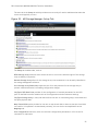
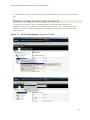
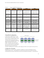
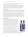
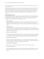
DELL PowerVault MD3200i/MD3220i Series of Storage Arrays A Dell Technical Guide Book Version 1.0 DELL PowerVault MD3200i/MD3220i Technical Guide Book THIS WHITE PAPER IS FOR INFORMATIONAL PURPOSES ONLY, AND MAY CONTAIN TYPOGRAPHICAL ERRORS AND TECHNICAL INACCURACIES. THE CONTENT IS PROVIDED AS IS, WITHOUT EXPRESS OR IMPLIED WARRANTIES OF ANY KIND. © 2010 Dell Inc. All rights reserved. Reproduction of this material in any manner whatsoever without the express written permission of Dell Inc. is strictly forbidden. For more information, contact Dell. Dell, the DELL logo, and the DELL badge, PowerConnect, and PowerVault are trademarks of Dell Inc. Microsoft, Windows, and Windows Server are either trademarks or registered trademarks of Microsoft Corporation in the United States and/or other countries. Other trademarks and trade names may be used in this document to refer to either the entities claiming the marks and names or their products. Dell Inc. disclaims any proprietary interest in trademarks and trade names other than its own. June 2010 ii DELL PowerVault MD3200i/MD3220i Technical Guide Book Contents 1. Product Overview ...................................................................................................... 3 2.1 iSCSI ..................................................................................................................... 3 2.2 6Gb Serial Attached SCSI (SAS 2.0) ................................................................................ 4 3. Controller Architecture ............................................................................................... 5 3.1 MD3200i RAID Controller Module View - LEDs.................................................................... 6 4. Chassis ................................................................................................................... 8 4.1 Dimensions and Weight .............................................................................................. 8 4.2 Front View and Features ............................................................................................ 9 4.3 MD3200i and MD3220i Rear View ................................................................................. 12 4.4 Power Supply Indicator Codes .................................................................................... 13 5 Hard Drives ............................................................................................................. 14 5.1 Hard Drive Indicators .............................................................................................. 15 6. Storage Capacity Expansion ........................................................................................ 16 7. SAS Cables ............................................................................................................. 17 8. MD Storage Manager ................................................................................................. 18 8.1 MD3200i Series Storage Manager Software Packages ......................................................... 19 8.2 Enterprise Window ................................................................................................. 19 8.3 Array Window ....................................................................................................... 20 8.4 Recovery Guru ....................................................................................................... 27 9. Working with Physical and Logical Disks ......................................................................... 28 9.1 Disk Group Configuration .......................................................................................... 28 9.2 Virtual Disk Configuration ......................................................................................... 29 9.3 Configuration Metadata ........................................................................................... 29 9.4 Global Hot Spares ................................................................................................... 30 9.5 Storage Partitioning ................................................................................................ 30 9.6 Snapshot .............................................................................................................. 31 9.7 Virtual Disk Copy .................................................................................................... 31 9.8 Online Administration .............................................................................................. 32 9.9 iSCSI Support ........................................................................................................ 33 9.10 Host Operating System Support ................................................................................. 33 10 Environmental ........................................................................................................ 33 10.1 Power Supply Specs ............................................................................................... 33 10.2 Thermal management ............................................................................................ 34 10.3 Over-Temperature Shutdown ................................................................................... 34 1 DELL PowerVault MD3200i/MD3220i Technical Guide Book 10.4 Environmental Specifications ................................................................................... 35 11. Configuration Guidelines .......................................................................................... 36 11.1 General Configuration Rules .................................................................................... 36 Tables Table 1. Selected Controller Features: ............................................................................. 7 Table 2. Detailed Dimensions (mm) ................................................................................. 8 Table 3. MD3200i and MD3220i Front Panel Feature Description ............................................ 11 Table 4. Supported Drives ........................................................................................... 14 Table 5. Supported RAID Configurations .......................................................................... 29 Table 6. Power Supply Specifications ............................................................................. 34 Table 7. Environmental Specifications ............................................................................ 35 Figures Figure 1. RAID controller architecture of the MD3200i controller. ............................................. 5 Figure 2. MD3200i RAID Controller Module View - LEDs............................................................ 6 Figure 3. MD3200i and MD3220i Dimensions ......................................................................... 8 Figure 4. MD3200i Front View and Features ......................................................................... 9 Figure 5. MD3200i Front Panel Indicators ............................................................................ 9 Figure 6. MD3220i Front View and Features ....................................................................... 10 Figure 7. MD3200i Front Panel Indicators .......................................................................... 12 Figure 8. MD3200i and MD3220i Front Bezel Feature and Indicators .......................................... 12 Figure 9. MD3200i and MD3220i Rear View ......................................................................... 12 Figure 10. Power Supply Indicator Codes ........................................................................... 12 Figure 11. Hard Drive Indicators (includes HDD and SSD) ........................................................ 15 Figure 12. Expansion and cabling .................................................................................... 16 Figure 13. Mini-SAS Cable Transition ................................................................................ 17 Figure 14. MD Storage Manager: Enterprise Window ............................................................. 19 Figure 15. MD Storage Manager: Setup Tab ........................................................................ 20 Figure 16. MD Storage Manager: Array Window.................................................................... 21 Figure 17. MD Storage Manager: Logical Tab ....................................................................... 22 Figure 18. MD Storage Manager: Physical Tab ..................................................................... 23 Figure 19. MD Storage Manager: Mappings Tab .................................................................... 24 Figure 20. MD Storage Manager: Setup Tab ........................................................................ 25 Figure 21. MD Storage Manager: Access to Tasks .................................................................. 26 Figure 22. MD Storage Manager: Support Tab ...................................................................... 27 2 DELL PowerVault MD3200i/MD3220i Technical Guide Book Product Overview The MD3200i series of storage arrays were designed with performance in mind. Each controller is equipped with four 1Gb Ethernet ports providing total aggregated bandwidth of 800MB/s of throughput for a dual controller system which is double the throughput of the MD3000i and most competitive products in the entry-level iSCSI SAN array market. For small block random access applications like databases, the MD3200i series is capable of performing over 2X the IOP performance of the MD3000i making it a great platform for a wide variety of applications and IT environments. When it comes to flexibility, the MD3200i series of storage arrays is second to none. There are four base offerings to choose from allowing users to best meet their specific IT demands and budgets. • • • • MD3200i single controller model – A single RAID controller in a 2U, 12 drive 3.5” HDD enclosure provides the lowest cost with the highest storage capacity offering when using large near-line SAS drives. MD3200i dual controller model – Dual, active/active controllers in a 2U, 12 drive 3.5” HDD enclosure provides a high availability and high capacity storage offering when using large nearline SAS drives. MD3220i single controller model – A single RAID controller in a 2U, 24 drive 2.5” HDD enclosure provides a low cost, high spindle count storage solution that maximizes IOPS when using SSD or 15K, 2.5” SAS drives. MD3220i dual controller model – Dual, active/active controllers in a 2U, 24 drive 2.5” HDD enclosure provides the combination of a highly available storage solution with a high spindle count to maximize IOPS when using SSD or 15K, 2.5” SAS drives. This series of arrays raises the bar for scalability in the entry-level storage space. Each model is capable of support up to 32 physical servers when connected to one or more 1Gb Ethernet switches. Additional storage capacity can be added up to a maximum of 96 HDD via the MD1200 and/or MD1220 enclosures. Users can also mix 3.5” and 2.5” enclosures behind their base units in order to achieve the optimal drive tiering that best matches their application needs. Within each enclosure users can mix SSD, SAS and near-line SAS drives maximizing their return on investment. In addition to the above mentioned features, the MD3200i series offers optional data protection features like snap shots and virtual disk copy services to assist users in protecting their data in a more effective manner. Initial set up is also much easier than the previous product with the addition of wizard enabled tools and improvements in the Modular Disk Storage Manager. iSCSI iSCSI (Internet Small Computer System Interface) is an industry standard that allows SCSI block I/O protocol to be sent over the network using a TCP/IP-based protocol for establishing and managing connections between IP-based storage devices, hosts and clients. iSCSI SAN solutions (often called IP SANs) consist of iSCSI initiators (software driver or adapter) in the application servers, connected to iSCSI arrays by means of standard Gigabit Ethernet switches, routers and cables. IP SANs are enabling organizations around the globe to maximize their existing IT investments while deploying effective and efficient networked data management solutions. iSCSI is particularly interesting as a SAN alternative to direct-attached storage in environments where simplicity, flexibility, price/performance and availability of administrative staff are critical IT decision factors. 3 DELL PowerVault MD3200i/MD3220i Technical Guide Book Advantages of iSCSI technology include: • Expansive Reach As a routable transport with no distance limitations, IP SANs can be located almost anywhere. The reach of a SAN throughout the organization is most often limited by the distance restriction of the interface. iSCSI removes these distance limitations to limitless boundaries and extends its scope well beyond the corporate data center to remote locations as well. • Minimal Investment iSCSI allows businesses to control their storage expenses without completely retro-fitting their existing network. iSCSI creates IP-based SANs which allows organizations to capitalize on components of their existing IP infrastructure by delivering block based storage across an IP network. Organizations do not have to invest in a new storage-only infrastructure, such as with FC which can be costly • Enormous Knowledge and Experience Base iSCSI allows almost all organizations to capitalize on existing IT skill sets to create IP-based SANs as in-house networking expertise is standard throughout most companies today. An end user does not have to learn a new networking protocol and go through extensive and sometimes expensive training, such as with FC. As a mature, well-understood technology with a broad range of proven management tools, iSCSI is easily deployed by administrators with LAN experience. 6Gb Serial Attached SCSI (SAS 2.0) SAS provides a scalable point-to-point topology capable of addressing storage connectivity at many levels. As SAS enters its second generation, the standard is evolving to enable better bandwidth utilization, easier management mechanisms, and network robustness. 6Gb/s SAS 2.0 not only doubles the current data transfer rate it provides standardized zoning, selfdiscovery, and self-configuration methods to expanders. This makes larger and more complex topologies easier than ever to implement. Key features of SAS 2.0 • • • • • • 6Gb/s SAS Signaling – doubles the transfer rate from 3Gb/s to 6Gb/s DFE (Decision Feedback Equalization) – increases cable limit to 10m ( 2 – 4 is typical) Supports SAS mini connectors (SFF-8088 and SFF-8087) SSC (Spread Spectrum Clocking ) – ease of design implementation – reduce peak amplitude of radiated emissions Supports SED (Self-Encrypting Drive) with Instant Secure Erase Delivers 2nd generation SAS Discovery • Standardized Zoning • Expanded to 256 devices • Discovery executed by SAS Expanders • Reduces time to discover large topologies 4 DELL PowerVault MD3200i/MD3220i Technical Guide Book Controller Architecture Figure 1. RAID controller architecture of the MD3200i controller. RJ 45 RJ45 RJ45 RJ45 SAS Exp RJ45 iSCSI TOE PCI-E X4 PCI-E 32-lane 8-port PCI-E Switch PCI-E 1Gb Eth NIC Flash BBU FPGA Cache Offload Assembly NVSRAM PCI-E X4 PCI-E SD 6Gb SAS 36 Port Expander 800MHz Power PC I2C Flash DDR-II 16 Bit Parallel Bus 2GB DDR-II X4 (Alt Ctrl) X24 (Drives) X4 (Alt Ctrl) SBB 2.0 Compliant Connector The RAID controllers are the “engines” or the “brains” of the MD3200i and MD3220i storage arrays. They perform the RAID calculations, control the I/O movement, communicate with the management client, store the firmware, and protect data until it can be written safely to the hard disk drives. The MD3200i’s architecture is designed to excel in multi-host systems environments. Its I/O system core provides built-in hardware XOR for high-speed RAID parity calculations – enabling it to easily handle very compute-intensive tasks. Each RAID controller contains 2GB of cache for a total of 4GB of cache in a dual controller configuration which is mirrored with the other controller’s cache for high availability. In the event of a power failure, the controllers are protected with battery assisted persistent cache backup which destages cache to non-volatile media for indefinite safe keeping. Each controller has a 36-port 6 Gb/s SAS expander that provides access to the drives in the MD3200i or MD3220i enclosure. The SAS expanders enable each controller to access all of the drive ports creating active/active drives loops that provide both controllers redundant access to all attached disk drives. 5 DELL PowerVault MD3200i/MD3220i Technical Guide Book Each controller has the following external connections: • Four 1Gb Ethernet ports for host connectivity • One 6 Gb/s SAS port for drive enclosure expansion for additional capacity • One Ethernet management ports for LAN out-of-band management • One PS/2 serial interface for service Figure 2. MD3200i RAID Controller Module View - LEDs 6Gb SAS port for drive expansion 1 Location 1 1Gb Ethernet port for management 1Gb Ethernet ports for host connectivity 2 3 4 5 LED Term Color Power Green PS/2 serial port for service 6 Icon l General Behavior OFF = No power applied ON = Power is applied 2 Controller Fault Amber OFF = The controller is operating normally ON = The controller has defaulted 3 4 Controller Identifier Blue Indicates the location of the enclosure within the system. Cache Active Green OFF = No data is in cache 6 DELL PowerVault MD3200i/MD3220i Technical Guide Book Location LED Term Color Icon General Behavior ON = Data is in cache Battery Fault Amber 5 6 OFF = The battery is operating normally ON = The battery has defaulted or is missing Password Reset Switch N/A A button which allows the user to reset the default MD Storage Manager password Table 1. Selected Controller Features: Automated I/O path protection with host-based, multipath failover drivers One or more virtual disks per disk group Automatic drive failure detection and rebuild using a global hot spare drive Up to 256 virtual disks Integrated storage partitioning, snapshot and virtual disk copy functionality Dynamic disk group expansion RAID levels 0, 1, 5, 6, 10 Dynamic virtual disk expansion Greater than 2TB virtual disk size support Dynamic RAID level migration Smart battery allows the controller to monitor different parameters on the cache offload batteries such as state-of-charge and state of health Dynamic capacity expansion Dynamic segment size migration Dynamic defragmentation Up to 30 hard disk drives per disk group in a RAID5 and RAID6 and up to 96 drives in a RAID0 or RAID1 Non-disruptive firmware upgrades 7 DELL PowerVault MD3200i/MD3220i Technical Guide Book Chassis Dimensions and Weight The PowerVault™ MD3200i and MD3220i enclosures use a rack mount 2U chassis. Table 2. Detailed Dimensions (mm) Model Number Xa Xb Y Za with bezel Za with bezel Zb Zc Max Sys Weight (kg) PV MD3200i 481.5 446.3 86.8 38.0 19.0 561.0 602.0 29.3 PV MD3220i 481.5 446.3 86.8 38.0 19.0 508.0 549.0 24.2 Figure 3. MD3200i and MD3220i Dimensions PowerVault™ MD3200i: Weight (maximum configuration) 29.3 kg (64.6 lb) PowerVault™ MD3220i: Weight (maximum configuration) 24.2 kg (53.4 lb) 8 DELL PowerVault MD3200i/MD3220i Technical Guide Book Figure 4. Front View and Features MD3200i Front View and Features Figure 5. MD3200i Front Panel Indicators 9 DELL PowerVault MD3200i/MD3220i Technical Guide Book Figure 6. MD3220i Front View and Features Figure 7. MD3200i Front Panel Indicators 10 DELL PowerVault MD3200i/MD3220i Technical Guide Book Table 3. MD3200i and MD3220i Front Panel Feature Description FRONT PANEL / BEZEL INDICATOR AND FETAURE DESCRIPTION Item 1 Indicator, Button, or Connector Enclosure status LED Icon Description The enclosure status LED lights when the enclosure power is on. Lights blue during normal operation and when the management software is identifying the enclosure. Blinks blue when the management software is identifying the enclosure or when the system identification button is pressed. Lights amber when the enclosure is turned on or is reset. Blinks amber when the enclosure is in the fault state. 5 2 Power LED The power LED lights when at least one power supply is supplying power to the enclosure. 3 Not Applicable This LED has no use in the MD3200i or MD3220i. 4 System Identification Button The system identification button on the front control panel can be used to locate a particular enclosure within a rack. When the button is pushed, the system status indicators on the control panel and the RAID controllers blinks blue until the button is pushed again. Hard Drives MD3200i—Up to 12 SAS hot-swappable drives. MD3220i—Up to 24 2.5-inch SAS hot-swappable drives. 6 Not Applicable This switch has no use on the MD3200i or MD3220i. 11 DELL PowerVault MD3200i/MD3220i Technical Guide Book Figure 8. MD3200i and MD3220i Front Bezel Feature and Indicators Figure 9. MD3200i and MD3220i Rear View RAID Controller Module 0 RAID Controller Module 1 Power Supply / Cooling Fan Modules 12 DELL PowerVault MD3200i/MD3220i Technical Guide Book Figure 10. Power Supply Indicator Codes Power Indicator Description POWER INDICATOR AND FETAURE DESCRIPTION Item 1 Indicator, Button, or Connector DC Power Icon Description The LED lights green when the DC output voltage is within the limit. If this LED is off, it indicates that the DC output voltages are not within the limit. 2 Power supply/cooling fan fault The LED lights amber when the DC output voltage is not within the limit or a fault with the fan is detected. If this LED is off, it indicates that no fault condition is present. 3 AC Power The LED lights green when the AC input voltage is within the limit. If this LED is off, it indicates either there is no power or the AC input voltage is not within the limit. 13 DELL PowerVault MD3200i/MD3220i Technical Guide Book Hard Drives The MD3200i and MD3220i support SAS hot-pluggable HDDs (hard-disk drives) and SSD (solid-state drives). MD3200i allows for both 3.5-inch and 2.5-inch form factor drives, and the MD3220i allows for 2.5-inch form factor drives. Note that 2.5” HDD in the MD3200i requires a unique drive carrier that houses a 2.5” HDD and fits into a 3.5” HDD slot. Any combination of SAS rotational speeds and SSD drives can be mixed within an MD3200i or MD3220i enclosure. Table 4. Supported Drives Form Factor 2.5” SAS Speed (rpm) Capacity (GB) 7,200 500 GB 146 GB 10,000 600GB (postRTS) HDDs up to 6Gb/s SSDs up to 3Gb/s 300 GB 15,000 SSD 73 GB 146 GB 150 GB 500 GB 3.5” SAS 7,200 1 TB 2 TB 300 GB HDDs up to 6Gb/s 15,000 450 GB 600 GB SATA interface drives are not supported with the MD3200i and MD3220i. 6Gb/s SAS interface HDDs and 3Gb/s SAS interface SSDs are configured in the MD3200i and MD3220i, from Dell’s factory 3Gb/s SAS interface HDDs are supported in the field with the supported MD3200i carrier. The front bezel of the system contains a lock. A locked bezel secures the system hard drives. 14 DELL PowerVault MD3200i/MD3220i Technical Guide Book Hard Drive Indicators Figure 11. Hard Drive Indicators (includes HDD and SSD) Drive Indicator Description Drive-Status Indicator Pattern Condition (RAID Only) Blinks green two times per second Identify drive/preparing for removal Off Drive ready for insertion or removal NOTE: The drive status indicator remains off until all hard drives are initialized after system power is turned on. Drives are not ready for insertion or removal during this time. Blinks green, amber, and off Drive predicted failure Blinks amber four times per second Drive failed Blinks green slowly Drive rebuilding Steady green Drive online 15 DELL PowerVault MD3200i/MD3220i Technical Guide Book Drive-Status Indicator Pattern Condition (RAID Only) Blinks green three seconds, amber three seconds, and off six seconds. Rebuild aborted Storage Capacity Expansion Both the MD3200i and MD3220i systems are capable of supporting up to 96 total hard drives. Adding additional drives past what the base platforms hold is a simple matter of connecting either MD1200 and/or MD1220 JBODs to the expansion ports on the MD3200i series of arrays. Users can mix and match the MD1200 (3.5” HDD enclosure) and the MD1220 (2.5” HDD enclosure) in any combination that provides them the best mix of drives for their environment as long as they don’t exceed a total of 96 drive slots. The diagram below shows the proper way to cable JBODs to the MD3200i series of storage arrays. If using 100% MD1200 enclosures for storage expansion on an MD3200i a total of seven MD1200 enclosures can be added to achieve a total of 96 HDD. If using 100% MD1220 enclosures for expansion on an MD3200i, a total of three MD1220 enclosures can be connected. Adding three MD1220 enclosures provides a total of 84 HDD slots. If using 100% MD1220 enclosures for storage expansion on an MD3220i, a total of three MD1220 enclosures can be added to achieve a total of 96 HDD. If using 100% MD1200 enclosures for expansion on an MD3220i, a total of six MD1200 enclosures can be added to achieve a total of 96 HDD. It is important to note that the older 3Gb SAS JBODS (MD1000 and MD1120) cannot be used as expansion enclosures on the MD3200i or the MD3220i. Figure 12. Expansion and cabling 16 DELL PowerVault MD3200i/MD3220i Technical Guide Book SAS Cables The MD3200i and MD3220i arrays and the MD1200 and MD1220 JBODs standardize on the 6Gb/s (SAS 2.0) mini-SAS cable (SFF 8088). The Mini-SAS cable is unique from the SAS cable used with the previous MD3000i array and MD1000 JBOD. Figure 13. Mini-SAS Cable Transition • Connectors on both ends of the Mini-SAS cable are universally keyed. Either end of the cable can be connected to the MD3200i RAID controllers or JBODs. • To remove the Mini-SAS cable, pull the pull-tab to release the cable from the connector on the EMM and the host system. 17 DELL PowerVault MD3200i/MD3220i Technical Guide Book MD Storage Manager The MD Storage Manager provides the perfect combination of robustness and ease-of-use—two attributes not commonly found together in an entry-level storage management tool. The new MD Storage Manager graphical user interface (GUI) is ideally suited for the full-time storage administrator, who wants complete control over their storage configuration, as well as the part-time system administrator, who needs an intuitive interface that helps them ensure optimal storage utilization. Features of the next generation MD Storage Manager: • Automated I/O path protection with host-based, multipath, failover drivers • Centralized management of one or more MD3200i and/or MD3220i arrays from any location • Backwards compatibility with MD3000 and/or MD3000i arrays • Integrated storage partitioning, snapshot and virtual disk copy functionality • o Support for up to 32 partitions o Support for up to 8 snapshots per virtual disk and a total of 128 snapshots per system o Support for up to 8 simultaneous virtual disk copies per array and a total of 255 copies per system. RAID levels 0, 1, 5, 10 and 6 supported o Up to 30 physical disks supported per disk group (RAID levels 5 and 6) o Up to 96 drives in RAID level 0 o Up to 96 drives in RAID level 1/10 • Local key management for SDE enabled drives • One or more virtual disks per disk group • Up to 256 virtual disks (LUNs) per array • Dynamic capabilities support on-the-fly reconfigurations • o Dynamic disk group expansion o Dynamic RAID level migration o Dynamic virtual disks expansion o Dynamic capacity expansion o Dynamic segment size migration o Dynamic defragmentation o Non-disruptive firmware upgrades Support for unlimited hot spares 18 DELL PowerVault MD3200i/MD3220i Technical Guide Book MD3200i Series Storage Manager Software Packages The MD3200i series Storage Manager software contains the following four packages: • Client – This package contains the graphical user interfaces (GUI) for monitoring and managing the storage arrays. It also contains an optional monitor service used to send alerts when there is a critical problem with the storage arrays. • Utilities – This package contains utilities like the MD Configuration Utility that greatly simplifies the steps required to set up iSCSI connections for the storage array and the host servers. The package also contains several providers to simplify integration with Microsoft tools (VSS and VDS) and integration to 3rd party management tools that take advantage of SMI-S protocols. • Agent – This package contains software that allows a storage management station to communicate with the controllers in the storage array over the I/O path of a host. • Failover Driver – This package contains the multi-path driver used to manage the I/O paths into the controllers in the storage array. If there is a problem on the path or a failure of one of the controllers, the driver automatically re-routes the request from the hosts to the other controller in the storage array. Enterprise Window The Enterprise Window is the main window that opens when the MD Storage Manager is initially launched. Within the Device tab, it provides a view of all of the storage arrays, including partially managed storage arrays, in the overall management domain. It also allows for the automatic or manual addition and removal of storage arrays and provides a view of all the MD arrays including prior generation MD3000 and MD3000i arrays. Figure 14. MD Storage Manager: Enterprise Window 19 DELL PowerVault MD3200i/MD3220i Technical Guide Book The Enterprise Window Setup tab is also accessible in the Enterprise Window. This Setup tab provides quick access to common setup tasks. For example, from the Setup tab window, a user can upgrade controller firmware, set alert notifications (email and SNMP), and perform other high-level configuration functions. Figure 15. MD Storage Manager: Setup Tab There are two ways to select an array to manage from the Enterprise Window. This includes; • Clicking the Manage a Storage Array in the Setup tab, then select the desired storage array; or, • go to the Devices tab and double-click on a storage array Either of these two options will open the Array Window for the selected storage array. Array Window The Array Window provides all of the functions to configure, maintain and troubleshoot any individual storage array. Multiple Array Windows can be open at the same time to manage multiple storage arrays if the need to do so ever arises. The Array Window is designed to be both informative and intuitive. From any of the six primary tabs located on the Array Window - Summary, Logical, Physical, Mapping, Setup and Support – users can simply make changes on the fly to quickly adapt their array to meet their needs. 20 DELL PowerVault MD3200i/MD3220i Technical Guide Book Figure 16. MD Storage Manager: Array Window The Summary tab (shown above) provides administers with a quick look at all the pertinent information regarding the selected MD3200i or MD3220i storage array as well as links to various management tasks. These include: • A Status area which indicates whether the storage array is in an optimal state, whether there are any long-running operations in progress with the ability to view the operations and whether alert notifications have been set. If the array is in a non-optimal state, a link is provided to launch the Recovery Guru. The Recovery Guru provides valuable troubleshooting assistance by diagnosing storage array problems and determining the appropriate procedure to use for recovery. The Recovery Guru displays a summary list of storage array problems, detailed information about a selected problem, and recovery steps to follow for the selected problem. • The Capacity section provides an indication of the total capacity available on the storage array as well as the configured and available capacity. • The Disk Groups &Virtual Disks area provides basic information on the number of disk groups, virtual disks, and RAID levels used on the storage array. In addition, a link is provided to allow the user to view additional disk group and virtual disk information in a non-embedded dialog. • The Hardware Components area provides basic hardware information about the selected storage array such as the number of physical disks, media types and if there are any configured hot spare physical disks. 21 DELL PowerVault MD3200i/MD3220i Technical Guide Book • The Hosts & Mappings area provides information about the number of hosts, virtual disk mappings, and storage partitions that have been configured. There is also a link provided to allow the user to get more detailed information about the hosts and mappings by launching a non-embedded dialog. • The Information Center area provides links to various help-related information and tutorials. The Logical tab is the second tab accessible from the Array Window and contains two panes: the Logical pane and the Properties pane. Figure 17. MD Storage Manager: Logical Tab The Logical pane provides a tree-structured view of the array’s disk configurations. Clicking the plus (+) sign or the minus (-) sign adjacent to the array will expand or collapse the view. These views under the storage array include un-configured capacity as well as configured disk groups and their associated virtual disks. Snapshots, if any, can also be viewed from the virtual disk in which they reside. The Properties pane provides detailed information about the component selected in the Logical pane. The information varies depending on what type of component is selected. Information may include whether the component is in an optimal status, total capacity, RAID level, media and interface type as well as controller ownership. The physical component’s overview is provided in the Properties pane and is associated with the logical component selected in the Logical pane. A greater detailed view can be found by right22 DELL PowerVault MD3200i/MD3220i Technical Guide Book clicking a component, and selecting “View Associated Physical Components”. This physical view can also be retrieved by selecting the Physical tab which will be covered next. The Physical tab provides both a physical view of the storage array as well as detailed information regarding the physical components. Within the Physical tab, the Physical pane appears on the left and the Properties pane appears on the right. The Physical pane shows a graphical representation of the physical components in the storage subsystem, such as the RAID controller modules and the expansion enclosures while the Properties pane displays detailed information about the component that is selected in the Physical pane. Figure 18. MD Storage Manager: Physical Tab The drop down menu in the Physical pane allows the user select which physical components they would like displayed in the Properties pane. Next, is the Mappings tab which provides an overall view of the host-to-virtual disk mappings configured on the storage array. The Mappings window includes both a Topology pane as well as a Defined Mappings pane. 23 DELL PowerVault MD3200i/MD3220i Technical Guide Book Figure 19. MD Storage Manager: Mappings Tab The Topology pane shows a tree-structured view of virtual disk that are related to the storage partitions. Click the plus (+) sign or the minus (-) sign adjacent to a node to expand or collapse the view. Users can right-click a node to open a pop-up menu that contains the applicable actions for that node. Views include undefined mappings within the storage array as well as the servers connected to the storage array. Once a virtual disk is selected, the Defined Mappings pane will provide mapping information pertinent to that node. By clicking on the storage array for example, the virtual drives associated with the storage array will be listed as well which hosts they are accessible by. By selecting a host, the user can also see a list of virtual disks assigned to it. The user can also create mappings by right-clicking on a virtual disk in the Topology pane and selecting “Partitioning”, which allows them to create mappings via a Wizard and will quickly create a new single partition. A user can also select “Define Additional Mappings” to define additional mappings. This step allows the user to map the virtual disk to additional host of host groups in an existing storage partition. 24 DELL PowerVault MD3200i/MD3220i Technical Guide Book The next tab is the Setup tab which provides access to nearly all routine administrative tasks that a user would typically run into. Figure 20. MD Storage Manager: Setup Tab The Setup tab includes tasks, such as: Blink Storage Array selection which allows the user to turn on the indicator lights of the storage array to identify it physically. Rename Storage Array allows for the storage array to be renamed so it can be easily identified in the storage management software. Set a Storage Array Password prompts the user for a new password for the storage array to prevent unauthorized users from making configuration changes. Configure iSCSI Host Ports provides for the configuration of network parameters for the iSCSI ports on the RAID controller module such as IP configuration and other advanced settings. Configure Storage Array is a key task which allows the user to create disk groups, virtual disks and hot spare physical disks. Map Virtual Disks option provides for the user to map virtual disks to hosts to that the virtual disk can used for I/O operations. As mentioned previously, this can also be accomplished from the Mappings tab. Save Configuration selection, users can save their configuration parameters in a file to use for restoration or replication. 25 DELL PowerVault MD3200i/MD3220i Technical Guide Book It is important to note that many tasks can also be accessed from the pull down menus across the top; or, by going to the Logical, Physical or Mappings tabs in the AW and right-clicking on the appropriate object (i.e. storage array, virtual disk drive, controller, etc.). For example, rightclicking on an array provides the same options as clicking on the Setup tab or the top pull down menus options. Figure 21. MD Storage Manager: Access to Tasks 26 DELL PowerVault MD3200i/MD3220i Technical Guide Book The final tab is the Support tab which provides a central location when storage array recovery, support information or a description of the storage array components are needed. Figure 22. MD Storage Manager: Support Tab Gather Support Information selection allows a user to save information about the storage array (such as its profile and event log information) to a file so that it can be saved and sent it to technical support. Storage Array Profile provides a detailed description of all components and properties of the storage array such as the number of physical drives used, firmware versions of the controller(s), which components are running optimally and the number of Snapshots taken. Download Firmware option allows the user to download RAID controller module firmware, NVSRAM, physical disk firmware, environmental management module (EMM) firmware and EMM configuration settings. View Event Log will provide a detailed list of storage array events. View Online Help is available for detailed instructions on how to accomplish any of the tasks in the Array Window to optimally configure the storage array. Recovery Guru If a problem should ever arise with the array, the Recovery Guru provides valuable troubleshooting assistance by diagnosing storage array problems and determining the appropriate procedure to use for recovery. The Recovery Guru displays a summary list of storage array problems, detailed information 27 DELL PowerVault MD3200i/MD3220i Technical Guide Book about a selected problem, and recovery steps to follow for the selected problem.Working with Physical and Logical Disks Disk Group Configuration A disk group is a set of physical disks that the controller logically groups together to provide one or more virtual Disk Group A disks to a host. Each disk group is comprised of the same drive technology (i.e. SAS, near-line SAS or SSD) and has an assigned RAID level. While multiple RAID levels can be intermixed in a single MD3200i series storage array, each disk group has a single RAID level. The number of physical disks that make up a disk group can be selected manually or automatically. When using Disk Disk Disk the MD Storage Manager software’s automatic 2 1 3 configuration option, disk groups will be configured balancing the load across as many physical disk channels and physical disk modules as possible. This ensures maximum protection and performance. Disk 4 MD Storage Manager software also provides the ability to dynamically add additional physical disks to existing disk groups. Existing virtual disks are then re-striped across all physical disks in the newly expanded disk group. This takes place while the disk group and all its virtual disks remain online and accessible for I/O. The selection of the RAID configurations is equally critical for each application to meet the desired data availability, performance or capacity requirements. And like physical disk types and configuration settings, the MD3200i series of arrays support the intermixing of RAID configurations to provide maximum flexibility and utilization. RAID 5 is generally considered the best balance of cost, performance and reliability. The table below outlines the tradeoffs of the various supported RAID configurations. 28 DELL PowerVault MD3200i/MD3220i Technical Guide Book Table 5. Supported RAID Configurations RAID-0 RAID-1 and 1+0 RAID-5 RAID-6 Physical disks operated Physical disks operated Data is “mirrored” independently with data independently with data and parity blocks and dual parity blocks are to another physical disk. distributed across all distributed across all physical disks in the group. physical disks in the group. Description Data is striped across multiple physical disks. Min # of physical disks in a disk group 1 2 3 4 Max # of physical disks in a disk group 96 96 30 30 Usable capacity as % of raw capacity 100% 50% 66.67% to 96.67% 50% to 93.33% Application IOPS | MB/s IOPS IOPS | MB/s IOPS | MB/s Advantages Disadvantages Good for reads, small IOPS, Same advantages as RAID-5 Performance due to Performance as many concurrent IOPS and but with better data parallel multiple requests random I/Os. Parity protection. Two hard operation of the can be fulfilled utilizes small portion of drives can fail without access simultaneously raw capacity. losing access to data. No redundancy. One physical disk fails, data is lost Storage costs are doubled Writes are particularly demanding Overhead on writes will be slightly more demanding than RAID-5 Virtual Disk Configuration Disk Group A A virtual disk is a logical structure on a storage array for data storage. A virtual disk is created by slicing a disk group into a stripe set with a defined capacity. Each Virtual Disk disk group supports up to one or more Marketing virtual disks and a maximum of 256 virtual disks per MD3200i series of storage system. During the virtual disk creation Disk Disk Disk Disk 2 4 1 3 process, the user specifies the capacity of the virtual disk and the virtual disk name. Additional settings include preferred controller ownership and a virtual disk-to-LUN mapping parameter (See Storage Partitioning section). Configuration Metadata MD3200i series of controllers store configuration metadata in a private 512 MB region on every configured physical disk. This metadata area contains physical disk state and status information, virtual disk state and status information and controller and subsystem information. The metadata on 29 DELL PowerVault MD3200i/MD3220i Technical Guide Book each physical disk stores that physical disk’s state and status, the worldwide name of its disk group, the virtual disks it contains and the definitions for those virtual disks. Storing metadata in this nonvolatile region provides the highest availability and enables easier reconfigurations and migrations. As system configuration data resides on every configured physical disk, controllers and/or multiple physical disks can be removed or swapped without losing the system configuration. Physical disks can be relocated within the storage system to improve channel utilization/protection or even migrated as a complete disk group into another storage system. In instances, all configuration metadata and user data remains intact on the physical disks. Global Hot Spares If a physical disk fails in the MD3200i or MD3220i storage array, the controller uses redundancy data to reconstruct the data onto a hot spare physical disk. The hot spare is automatically substituted for the failed physical disk without requiring user intervention. Once the failed drive is replaced, the data is then automatically copied back to the new drive. The user then has a choice of allowing the hot spare to return to its role as a hot spare drive or become a permanent member of a disk group, therefore, eliminating the copy back process. The replacement drive, in this case, would then be in an unassigned state. This feature may be appealing as it reduces the degraded mode time by avoiding the copy back process. The MD3200i and MD3220i storage arrays both support an unlimited number of global hot spare physical disks, and each can be a spare for any like-technology disk in the array (i.e. SAS for SAS, near-line SAS for near-line SAS and SSD for SSD). Generally speaking, the physical disks that are assigned as a hot spares should have a capacity that is equal to or greater than the capacity of the largest physical disk in the storage array. Storage Partitioning The MD3200i series of arrays Storage Partitioning feature enables a single storage array to be logically partitioned and function as up to 32 virtual arrays. A storage partition is a logical entity consisting of one or more virtual disks that are accessed by a single host or shared among a collection of hosts that are part of a host group. A storage partition is created when one or more virtual disks are mapped to an individual host or host group. This virtual disk-to-LUN mapping allows you to define what host or host group will have access to a particular virtual disk in your storage system. Hosts and host groups can only access data through assigned virtual disk-toLUN mappings. Partition access is maintained at the controller level, ensuring complete data integrity in multi-host, multi-OS environments. The virtual disk-to-LUN mapping implementation creates valuable flexibility for the storage administrator as any available virtual disk can be mapped to any attached server. So, while the individual servers see a virtual array that consists of only their LUNs/virtual disks, the virtual disks can be intermixed throughout the storage system within one or more disk groups. Host A Host B Logical partition A Logical partition B LUN LUN LUN LUN LUN The system’s logical partitioning combined with its configuration capabilities enables administrators to choose from a range of virtual disks with different unmapped characteristics to meet a server's exact needs for a given application. A virtual disk given host can concurrently have virtual disks with different capacities, different RAID levels, and different physical disk types. This flexibility enables hosts with different capacity, performance or data protection demands to effectively share a single storage array. 30 DELL PowerVault MD3200i/MD3220i Technical Guide Book Snapshot The MD3200i series of arrays Snapshot functionality provides an additional level of data protection and the means to improve production data utilization. Snapshot enables nonproduction servers to access an up-to-date copy of production data for a variety of applications – including backup, application testing, or data mining – while the production data remains online and user-accessible. A snapshot is a point-in-time image of a source virtual disk. It is the logical equivalent of a complete physical copy, but is created much more quickly and requires less disk space. Snapshots appear and function as standard virtual disks; they are host-addressable and can be read, written to or copied. Snapshot Virtual Disk Source Virtual Disk Snapshot Repository Snapshot uses an innovative copy-on-write technology to Logical maintain the logical snapshot virtual disk while minimizing Physical disk utilization. When the snapshot is “taken,” the controller suspends I/O to the source virtual disk for a few seconds while it creates a new physical virtual disk – called the repository virtual disk – to store snapshot metadata and copy-on-write data. When a data block on the source virtual disk is modified, a copy-on-write occurs, copying the contents of blocks that are to be modified into the repository virtual disk for safekeeping. This repository virtual disk combined with the original source virtual disk creates the logical snapshot virtual disk. Since the only data blocks that are physically stored in the repository virtual disk are those that have changed since the time of the snapshot, the snapshot technology uses less disk space than a full physical copy. The repository virtual disk is typically 20 percent of the base virtual disk, but will vary depending on the amount of changes to the data. The longer a snapshot is active, the larger the repository is needed. Virtual disk snapshot provides notification when the repository virtual disk nears a user-specified threshold (a percentage of its full capacity). And at any time, the volume expansion feature can be used to dynamically expand the repository virtual disk. Virtual Disk Copy The MD3200i series of arrays Virtual Disk Copy functionality provides administrators with another tool to effectively manage information growth and maximize the utilization of the storage array. Virtual disk copy creates a complete physical copy, or a clone, of a virtual disk within a storage array. The clone virtual disk is a unique entity that can be assigned to any host and used by applications requiring a point-in-time (PiT) copy of production data – such as backup, application testing or development, information analysis or data mining – without affecting the performance of the production virtual disk. Virtual disk copy is configured and accessed via easy-to-use wizards. It supports up to eight concurrent copies taking place within a single array. Virtual disk copy is a background operation with five user-defined priority settings, enabling administrators to minimize either copy time or the overall I/O impact to the storage system. As virtual disk copy is controller Base Virtual disk PiT Clone Virtual disk Copy 31 DELL PowerVault MD3200i/MD3220i Technical Guide Book based, it requires no host interaction or CPU cycles – minimizing the impact to applications and the storage infrastructure. Virtual disk copy can be used in conjunction with virtual disk snapshot – which creates a PiT image of a virtual disk while maintaining read / write access – enabling a complete PiT clone to be created without interrupting the I/O activity of the production virtual disk. Additionally, virtual disk copy can be used to redistribute data – moving virtual disks from older, slower disk physical disks to newer, faster, or higher capacity physical disks – to optimize application performance and/or capacity utilization. Online Administration The MD3200i series of storage arrays allows primary storage management tasks to be performed while the storage remains online with complete read/write data access. This allows storage administrators to make configuration changes, conduct maintenance, or expand the storage capacity without disrupting I/O to its attached hosts. Online capabilities include: • Add Free Capacity Capacity Expansion enables the capacity and number of physical disks to be increased for a given disk group. Up to two physical disks at a time can be added to existing disk groups, with the existing virtual disks then being striped across the full set of physical disks now comprising the disk group. • Dynamic Expansion This feature enables new drive modules to be added, virtual disk groups to be configured, and virtual disks to be created without disrupting access to existing data. Once a newly created virtual disk is defined, the array provides immediate virtual disk availability and is enable it to be instantly mapped and accessed by a host(s). • Dynamic Virtual Disk Expansion This feature allows for the capacity expansion of an existing virtual disk by using the free capacity on an existing virtual disk group. And since dynamic virtual disk expansion concatenates (combines) the new capacity with the original capacity, maximum performance and utilization is assured. • Dynamic RAID Level Migration This level of migration changes the RAID level of a virtual group on the existing drives, without requiring the relocation of data. With this dynamic feature, customers can easily adjust RAID levels when their application, availability, or performance needs change. • Dynamic Segment Size Migration With this feature, the segment size of a given virtual disk can be dynamically changed. • Dynamic Defragmentation Dynamic defragmentation allows the user to rearrange virtual disks and consolidates free capacity within a virtual disk group resulting in optimized access patterns for existing and newly created volumes. 32 DELL PowerVault MD3200i/MD3220i Technical Guide Book • Non-disruptive firmware upgrades Enables controller firmware upgrades to occur with no interruption to data access. The new firmware is transferred to the first controller, its flash memory is updated, and the controller is rebooted. The firmware is then passed from the first controller to the second, and the process is repeated. With a multi-path driver installed, access to all storage arrays’ virtual disks is maintained throughout the process. iSCSI Support The MD3200i series of storage arrays support all industry-standard GbE switches and NICs. The MD3200i series of arrays do not support 10/100 directly connected to the array with the exception being the management port. The free initiators that ship with the Windows and Linux operating systems are the preferred connectivity choice for the arrays. These initiators provide ample performance for this class of array. Host Operating System Support The MD3200i series of storage arrays support the following operating systems: • Microsoft Windows 2008 • Microsoft Windows 2003 • Microsoft Hyper-V • RedHat Enterprise Linux • SuSE Enterprise Linux • VMware • Xen Server Please consult with the MD3200i/MD3220i Support Matrix for a complete list of supported configurations. Environmental Power Supply Specs The PowerVault™ MD3200i and MD3220i power supply is rated at 600 W. It operates on input voltages ranging from 100 – 240 V, auto-switching to the sensed line level. EMC classification is Light Industry FCC classification is Class A 33 DELL PowerVault MD3200i/MD3220i Technical Guide Book Table 6. Power Supply Specifications AC Characteristics INPUT PARAMETER Requirement Input Voltage Range 90 – 264 VAC Input Frequency 47 – 63 Hz Peak Inrush Current 55 A for 10ms or less, 25 A for 10-150ms Power Factor over full AC input range 0.9 @ output load > 90% Minimum Efficiency measured 20%, 50% and 80% output load over full range of AC input and environmental conditions Must Meet Climate Savers requirements: Load Condition Peak Output Power Efficiency 20% 87% 50% 90% 100% 87% 600 Watts Thermal management The cooling system for the enclosure is designed to allow all components (power supplies, RAID controllers, HDDs, SSDs etc.) to meet their full operating specifications. There may be up to four fans in each power supply/fan module. This configuration provides N+1 fan redundancy, meaning that the enclosure can be sufficiently cooled for normal operation even if one fan fails. Firmware shall continuously monitor the temperature sensors within the enclosure and take proper actions to throttle the fans in order to maintain optimal operating temperature. Over-Temperature Shutdown In order to prevent potential damage to the drives and subsequent loss of data, the power supply has the capability to shut itself down or be shut down by the RAID controller in the event of an overtemperature condition. When the power supply incorporates its internal thermal shutdown feature, it will automatically restart when the over temperature condition no longer exists. Hysteresis of at least 5 degrees is employed to prevent a frequent toggling on and off of the outputs. 34 DELL PowerVault MD3200i/MD3220i Technical Guide Book Environmental Specifications Table 7. Environmental Specifications Temperature Operating 10° to 35°C (50° to 95°F) with a maximum temperature gradation of 10°C per hour Note: For altitudes above 2950 feet, the maximum operating temperature is de-rated 1°F/550 ft. Storage -40° to 65°C (-40° to 149°F) with a maximum temperature gradation of 20°C per hour Relative Humidity Operating 20% to 80% (non-condensing) with a maximum humidity gradation of 10% per hour Storage 5% to 95% (non-condensing) with a maximum humidity gradation of 10% per hour Maximum Vibration Operating 0.25 G at 3 – 200 Hz for 15 min Storage 0.5 at 3 – 200 Hz for 15 min Maximum Shock Operating One shock pulse in the positive z axis (one pulse on each side of the system) of 31 G for 2.6 ms in the operational orientation Storage Six consecutively executed shock pulses in the positive and negative x, y, and z axes (one pulse on each side of the system) of 71 G for up to 2 ms Altitude Operating -16 to 3048 m (-50 to 10,000 ft) Note: For altitudes above 2950 feet, the maximum operating temperature is de-rated 1°F/550 ft. Storage -16 to 10,600 m (-50 to 35,000 ft) Airborne Contaminant Level Class G2 or lower as defined by ISA-S71.04-1985 35 DELL PowerVault MD3200i/MD3220i Technical Guide Book Configuration Guidelines General Configuration Rules The MD3200i and MD3220i’s extensive configuration flexibility enables customized performance tuning, maximum capacity utilization and the highest data protection to support application servers with vastly different requirements. A single storage array can concurrently support multiple RAID levels (0, 1, 5, 10 and 6), multiple drive technologies (SSD, SAS and near-line SAS), multiple and various disk group sizes, and one or more virtual disks per disk group. Below are general configuration rules for MD3200i series of arrays. • Up to 8 direct attached servers with single I/O paths to a dual controller storage array • Up to 4 direct attached servers with redundant I/O paths to a dual controller storage array • Up to 32 physical hosts can be supported on a single storage system (includes both single and dual controller models) • Up to 96 total drives consisting of SSD, SAS and/or near-line SAS drives per storage system • SSD drives are limited to a single shelf (12 drives for a MD3200i or 24 drives for a MD3220i) • MD1200 and/or MD1220 storage enclosures can be add to a MD3200i or MD3220i storage array for expansion up to 96 total hard drives • Up to 30 hard disk drives per disk group in a RAID 5 and RAID 6 • Up to 96 hard disk drives per disk group in a RAID1/10 • Each disk group can be configured as RAID level 0, 1, 5, 10 or 6. • Disk groups with different RAID levels can coexist in a single storage system. • Disk groups are comprised of either SSD or SAS drives. A given disk group cannot have both SSD and SAS drives. • Up to 256 virtual disks (LUNs) per storage array • Each virtual disk can support 8 snapshots, with a maximum of 128 snapshots per storage array. 36