1
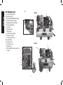
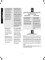
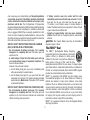
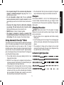
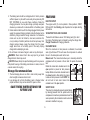
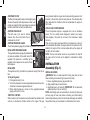
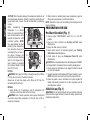
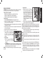
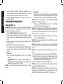
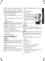
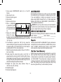
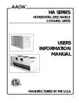
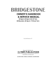
If you have questions or comments, contact us. Pour toute question ou tout commentaire, nous contacter. Si tiene dudas o comentarios, contáctenos. 1-800-4-DeWALT • www.dewalt.com Instruction Manual Guide D'utilisation Manual de instrucciones INSTRUCTIVO DE OPERACIÓN, CENTROS DE SERVICIO Y PÓLIZA DE GARANTÍA. ADVERTENCIA: LÉASE ESTE INSTRUCTIVO ANTES DE USAR EL PRODUCTO. D55690, D55695 Contractor’s Gas Wheeled Portable Air Compressor with electric start Compresseur d’air portatif à essence, sur roues, de classe entrepreneur Compresor de aire portátil a gasolina con ruedas para contratistas English Air Compressor Fig. 1 A.Pump Air Intake Filter B.Engine Air Filter C.Engine START/RUN/OFF Switch D.Air Tank Pressure Gauge E.Regulated Pressure Gauge F.Pressure Regulator G.Air Outlet H.Unloader Valve I.Safety Valve J.Air Tank Drain Valve(s) K.Pump Oil Fill Plug L.Pump Oil Drain Plug M.Fixed Throttle N.Choke Control O.Fuel Valve Lever P.Starter Grip Q.18V DeWALT battery pack and C charger D55690 A B M N P K L O I H J D55695 A b K D I Q F E H L G J 2 Specifications Pump Specifications MODEL WEIGHT HEIGHT WIDTH Length Air Tank Capacity (Gallons) Approx. blow off pressure scfm @ 100 psi Engine Specifications DeWALT 270 cc Internal Combustion 4-stroke High RPM 3000–3200 Idle RPM 1900–2200 Hot Surfaces Fig. 2 D55690 216 lbs. (97.98 kg) 28.81" (731.77 mm) 18.25" (463.55 mm) 43" (1092.2 mm) 8 (30.3 liters) D55695 238 lbs. (107.96 kg) 34.75" (882.65 mm) 20.25" (514.35 mm) 43" (1092.2 mm) 17 (64.4 liters) 150 PSI 150 PSI 16.3 16.3 OUTLET TUBE engine muffler OUTLET TUBE compressor cylinder & head compressor cylinder & head engine muffler pump crankcase gasoline engine pump crankcase gasoline engine D55690 D55695 3 English V - twin 4 cylinder Single Stage Oil Lubricated Cast iron crankcase, cylinder, and aluminum head Bore: 2.5" (63.5 mm) Stroke: 2.375" (60.33 mm) Weight: 69 lbs. (31.3 kg.) Oil Capacity: 30 oz. (887 mL) in the state of California. It is a violation of California statutes section 130050 and/or sections 4442 and 4443 of the California Public Resources Code, unless the engine is equipped with a spark arrester, as defined in section 4442, and maintained in effective working order. Spark arresters are also required on some U.S. Forest Service land and may also be legally required under other statutes and ordinances. WARNING: This product contains chemicals known to the State of California to cause cancer, and birth defects or other reproductive harm. Wash hands after handling. WARNING: Some dust contains chemicals known to the State of California to cause cancer, birth defects or other reproductive harm such as asbestos and lead in lead based paint. WARNING: The engine exhaust from this product contains chemicals known to the State of California to cause cancer, birth defects or other reproductive harm. English Definitions: Safety Guidelines The definitions below describe the level of severity for each signal word. Please read the manual and pay attention to these symbols. DANGER: Indicates an imminently hazardous situation which, if not avoided, will result in death or serious injury. WARNING: Indicates a potentially hazardous situation which, if not avoided, could result in death or serious injury. CAUTION: Indicates a potentially hazardous situation which, if not avoided, may result in minor or moderate injury. CAUTION: Used without the safety alert symbol indicates a potentially hazardous situation which, if not avoided, may result in property damage. Save these instruction IF YOU HAVE ANY QUESTIONS OR COMMENTS ABOUT THIS OR ANY DeWALT TOOL, CALL US TOLL FREE AT: 1-800-4-DeWALT (1-800-433-9258) DANGER: Risk of explosion or fire What can happen How to prevent it • Shut off engine and allow it to • Spilled gasoline and it’s cool before adding fuel to the vapors can become ignited tank. from cigarette sparks, electrical arcing, exhaust gases • Use care in filling tank to avoid and hot engine components spilling fuel. Move unit away such as the muffler. from fueling area before starting engine. Important Safety Instructions WARNING: Do not operate this unit until you read this instruction manual and the engine instruction manual for safety, operation and maintenance instructions. WARNING: This product may not be equipped with a sparkarresting muffler. If the product is not equipped and will be used around flammable materials or on land covered with materials such as agricultural crops, forest, brush, grass or other similar items, then an approved spark arrester must be installed and is legally required 4 • Improperly stored fuel could lead to accidental ignition. Fuel improperly secured could get into the hands of children or other unqualified persons. • Unattended operation of this product could result in personal injury or property damage. To reduce the risk of fire, do not allow the compressor to operate unattended. • Keep maximum fuel level 1/2" (12.7 mm) below bottom of filler neck to allow for expansion. • Add fuel outdoors in a well ventilated area. Make sure there are no sources of ignition, such as cigarettes near refueling location. • Operate compressor in a clean, dry, well ventilated area a minimum of 48" (1.22 m) from any building, object or wall. Do not operate unit indoors or in any confined area. • Operate compressor in an open area away from dry brush, weeds or other combustible materials. • Store fuel in an OSHAapproved container, in a secure location away from work area. • Always remain in attendance with the product when it is operating. DANGER: RISK TO BREATHING (Asphyxiation) What can happen How to prevent it • Breathing exhaust fumes • Always operate air compressor will cause serious injury outside in a clean, well or death! Engine exhaust con ventilated area. Avoid enclosed tains carbon monoxide, an areas such as garages, odorless and deadly gas. basements, storage sheds, which lack a steady exchange or air. Keep children, pets and others away from area of operation. 5 English • Heat will expand fuel in the tank which could result in spillage and possible fire explosion. • Combustible materials which come into contact with hot engine parts can become ignited. English • Air obtained directly from the compressor should never be used to supply air for human consumption. In order to use air produced by this compressor for breathing, suitable filters and in-line safety equipment must be properly installed. In-line filters and safety equipment used in conjunction with the compressor must be capable of treating air to all applicable local and federal codes prior to human consumption. • Work in an area with good • Exposure to chemicals cross ventilation. Read and in dust created by follow the safety instructions power sanding, sawing, provided on the label or grinding, drilling and other safety data sheets for the construction activities may materials you are spraying. be harmful. Always use certified safety • Sprayed materials such as equipment: NIOSH/OSHA paint, paint solvents, paint respiratory protection or remover, insecticides, weed properly fitting face mask killers, may contain harmful designed for use with your vapors and poisons. specific application. • The compressed air directly from your compressor is not safe for breathing. The air stream may contain carbon monoxide, toxic vapors or solid particles from the air tank. Breathing these contaminant's can cause serious injury or death. DANGER: Risk of Injury or Property Damage When Transporting or storing What can happen How to prevent it • Oil can leak or spill and could • Always place compressor on a protective mat when result in fire or breathing transporting to protect against hazard; serious injury or damage to vehicle from leaks. death can result. Oil leaks will Remove compressor from damage carpet, paint or other vehicle immediately upon arrival surfaces in vehicles or trailers. at your destination. Always keep compressor level and never lie on its side. WARNING: RISK of Bursting Air Tank: The air tank on your Air Compressor is designed and may be UM coded [for units with air tanks greater than 6" (152 mm) diameter] according to ASME Section VIII, Div. 1 rules. All pressure vessels should be inspected once every two years. To find your state pressure vessels inspector, look under the Division of Labor and Industries in the government section of a phone book or call 1-800-4-DeWALT for assistance. The following conditions could lead to a weakening of the air tank, and result in a violent air tank explosion: 6 • Modifications or attempted repairs to the air tank. • Unauthorized modifications to the unloader valve, safety valve, or any other components which control air tank pressure. • Excessive vibration can weaken the air tank and cause rupture or explosion. Excessive vibration will occur if the compressor is not properly mounted or if engine operates above recommended RPM. How to prevent it Attachments & accessories: • Exceeding the pressure rating • Follow the equipment of air tools, spray guns, air manufacturers recommendation operated accessories, tires and never exceed the maximum and other inflatables can allowable pressure rating cause them to explode or of attachments. Never use fly apart, and could result in compressor to inflate small serious injury. low pressure objects such as children’s toys, footballs, basketballs, etc. Tires: • Over inflation of tires could • Use a tire pressure gauge to result in serious injury and check the tires pressure before property damage. each use and while inflating tires; see the tire sidewall for the correct tire pressure. NOTE: Air tanks, compressors and similar equipment used to inflate tires can fill small tires similar to these very rapidly. Adjust pressure regulator on air supply to no more than the rating of the tire pressure. Add air in small increments and frequently use the tire gauge to prevent over inflation. • Drain air tank daily or after each use. If air tank develops a leak, replace it immediately with a new air tank or replace the entire compressor. • Never drill into, weld or make any modifications to the air tank or its attachments. Never attempt to repair a damaged or leaking air tank. Replace with a new air tank. • The air tank is designed to withstand specific operating pressures. Never make adjustments or parts substitutions to alter the factory set operating pressures. • Do not remove the stiffener bar connecting the compressor pump to the engine, except to adjust belt tension. Then securely tighten the stiffener bar bolts. This bar controls unit vibration. 7 English What can happen • Failure to properly drain condensed water from air tank, causing rust and thinning of the steel air tank. English WARNING: RISK OF Hot surfaces What can happen How to prevent it • Touching exposed metal such • Never touch any exposed as the compressor head, metal parts on compressor engine head, engine exhaust during or immediately after or outlet tubes, can result in operation. Compressor will serious burns. remain hot for several minutes after operation • Do not reach around protective shrouds or attempt maintenance until unit has been allowed to cool. WARNING: Risk from Flying Objects What can happen How to prevent it • Always wear certified safety • The compressed air stream equipment: ANSI Z87.1 eye can cause soft tissue damage protection (CAN/CSA Z94.3) to exposed skin and can with side shields when using propel dirt, chips, loose the compressor. particles and small objects at high speed, resulting in • Never point any nozzle or property damage or personal sprayer toward any part of injury. the body or at other people or animals. • Always turn the compressor off and bleed pressure from the air hose and air tank before attempting maintenance, attaching tools or accessories. WARNING: Risk from Moving Parts What can happen How to prevent it • The engine can start • Always disconnect the spark accidentally if the flywheel is plug and bleed pressure from turned by hand or moved by the air tank before performing pulling on the starter rope. maintenance. 8 • Attempting to operate compressor with damaged or missing parts or attempting to repair compressor with protective shrouds removed can expose you to moving parts and can result in serious injury. • Never operate the compressor with guards or covers which are damaged or removed. • Keep your hair, clothing and gloves away from moving parts. Loose clothes, jewelry or long hair can be caught in moving parts. • Air vents may cover moving parts and should be avoided as well. • Any repairs required on this product should be performed by a DeWALT factory service center or a DeWALT authorized service center. WARNING: Risk of Unsafe Operation What can happen How to prevent it • Unsafe operation of your air • Review and understand all instructions and warnings in this compressor could lead to seri manual. ous injury or death to you or others. • Become familiar with the oper ation and controls of the air compressor. • Keep operating area clear of all persons, pets, and obstacles. • Keep children away from the air compressor at all times. • Do not operate the product when fatigued or under the influence of alcohol or drugs. Stay alert at all times. • Never defeat the safety features of this product. • Equip area of operation with a fire extinguisher. • Do not operate machine with missing, broken, or unautho rized parts. • Never stand on the compressor. 9 English • Moving parts such as the pulley, flywheel, and belt can cause serious injury if they come into contact with you or your clothing. English Read all Instructions • Do not charge or use battery in explosive atmospheres, such as in the presence of flammable liquids, gases or dust. Inserting or removing the battery from the charger may ignite the dust or fumes. • Never force battery pack into charger. Do not modify battery pack in any way to fit into a non-compatible charger as battery pack may rupture causing serious personal injury. Consult the chart at the end of this manual for compatibility of batteries and chargers. • Charge the battery packs only in DeWalt chargers. • DO NOT splash or immerse in water or other liquids. • Do not store or use the tool and battery pack in locations where the temperature may reach or exceed 105°F (40˚) (such as outside sheds or metal buildings in summer). DANGER: Electrocution hazard. Never attempt to open the battery pack for any reason. If battery pack case is cracked or damaged, do not insert into charger. Do not crush, drop or damage battery pack. Do not use a battery pack or charger that has received a sharp blow, been dropped, run over or damaged in any way (i.e., pierced with a nail, hit with a hammer, stepped on). Electric shock or electrocution may result. Damaged battery packs should be returned to service center for recycling. NOTE: Battery storage and carrying caps are provided for use whenever the battery is out of the tool or charger. Remove cap before placing battery in charger or tool. WARNING: Fire hazard. Do not store or carry battery so that metal objects can contact exposed battery terminals. For example, do not place battery in aprons, pockets, tool boxes, product kit boxes, drawers, etc., with loose WARNING: RISK OF INJURY FROM LIFTING What can happen How to prevent it • Serious injury can result from • The compressor is too heavy attempting to lift too heavy to be lifted by one person. an object. Obtain assistance from others before lifting. CAUTION: risk from noise What can happen How to prevent it • Under some conditions and • Always wear certified safety duration of use, noise from equipment: ANSI S12.6 this product may contribute to (S3.19) hearing protection. hearing loss. SAVE THESE INSTRUCTIONS FOR FUTURE USE Important Safety Instructions for All Battery Packs An 18V DeWALT battery pack is used to start these units using the electric start feature. When ordering replacement battery packs, be sure to include catalog number and voltage. Consult the chart at the end of this manual for compatibility of chargers and battery packs. The battery pack is not fully charged out of the carton. Before using the battery pack and charger, read the following safety instructions. Then follow charging procedures outlined. 10 Specific Safety instructions for Nickel Cadmium (NiCd) or Nickel Metal Hydride (NiMH) • Do not incinerate the battery pack even if it is severely damaged or is completely worn out. The battery pack can explode in a fire. • A small leakage of liquid from the battery pack cells may occur under extreme usage or temperature conditions. This does not indicate a failure. However, if the outer seal is broken: a. and the battery liquid gets on your skin, immediately wash with soap and water for several minutes. b. and the battery liquid gets into your eyes, flush them with clean water for a minimum of 10 minutes and seek immediate medical attention. (Medical note: The liquid is 25-35% solution of potassium hydroxide.) The RBRC™ Seal The RBRC™ (Rechargeable Battery Recycling Corporation) Seal on the nickel cadmium, nickel metal hydride or lithium ion batteries (or battery packs) indicate that the costs to recycle these batteries (or battery packs) at the end of their useful life have already been paid by DeWALT. In some areas, it is illegal to place spent nickel cadmium, nickel metal hydride or lithium ion batteries in the trash or municipal solid waste stream and the RBRC program provides an environmentally conscious alternative. RBRC™ in cooperation with DeWALT and other battery users, has established programs in the United States and Canada to facilitate the collection of spent nickel cadmium, nickel metal hydride or lithium ion batteries. Help protect our environment and conserve natural resources by returning the spent nickel cadmium and nickel cadmium, nickel metal hydride or lithium ion batteries to an authorized DeWALT service center or to your local retailer for recycling. You may also contact your local recycling center for information on where to drop off the spent battery. RBRC™ is a registered trademark of the Rechargeable Battery Recycling Corporation. Specific Safety instructions for Lithium Ion (Li-Ion) • Do not incinerate the battery pack even if it is severely damaged or is completely worn out. The battery pack can explode in a fire. Toxic fumes and materials are created when lithium ion battery packs are burned. 11 English • If battery contents come into contact with the skin, immediately wash area with mild soap and water. If battery liquid gets into the eye, rinse water over the open eye for 15 minutes or until irritation ceases. If medical attention is needed, the battery electrolyte is composed of a mixture of liquid organic carbonates and lithium salts. • Contents of opened battery cells may cause respiratory irritation. Provide fresh air. If symptoms persists, seek medical attention. WARNING: Burn hazard. Battery liquid may be flammable if exposed to spark or flame. nails, screws, keys, etc. without battery cap. Transporting batteries can possibly cause fires if the battery terminals inadvertently come in contact with conductive materials such as keys, coins, hand tools and the like. The US Department of Transportation Hazardous Material Regulations (HMR) actually prohibit transporting batteries in commerce or on airplanes (i.e., packed in suitcases and carry-on luggage) UNLESS they are properly protected from short circuits. So when transporting individual batteries, make sure that the battery terminals are protected and well insulated from materials that could contact them and cause a short circuit. English Important Safety Instructions for all Battery Chargers • Make sure that cord is located so that it will not be stepped on, tripped over, or otherwise subjected to damage or stress. • Do not use an extension cord unless it is absolutely necessary. Use of improper extension cord could result in risk of fire, electric shock, or electrocution. • When operating a power tool outdoors, use an extension cord suitable for outdoor use. Use of a cord suitable for outdoor use reduces the risk of electric shock. • An extension cord must have adequate wire size (AWG or American Wire Gauge) for safety. The smaller the gauge number of the wire, the greater the capacity of the cable, that is 16 gauge has more capacity than 18 gauge. An undersized cord will cause a drop in line voltage resulting in loss of power and overheating. When using more than one extension to make up the total length, be sure each individual extension contains at least the minimum wire size. The following table shows the correct size to use depending on cord length and nameplate ampere rating. If in doubt, use the next heavier gauge. The smaller the gauge number, the heavier the cord. Recommended Minimum Wire Size for Extension Cords Total Length of Cord 25 ft. 50 ft. 75 ft. 100 ft. 125 ft. 150 ft. 175 ft. 7.6 m 15.2 m 22.9 m 30.5 m 38.1 m 45.7 m 53.3 m Wire Size AWG 18 18 16 16 14 14 12 • Do not place any object on top of charger or place the charger on a soft surface that might block the ventilation slots and result in excessive internal heat. Place the charger in a position away from any heat source. The charger is ventilated through slots in the top and the bottom of the housing. • Do not operate charger with damaged cord or plug. SAVE THESE INSTRUCTIONS: This manual contains important safety and operating instructions for battery chargers. • Before using charger, read all instructions and cautionary markings on charger, battery pack, and product using battery pack. DANGER: Electrocution hazard. 120 volts are present at charging terminals. Do not probe with conductive objects. Electric shock or electrocution may result. WARNING: Shock hazard. Do not allow any liquid to get inside charger. Electric shock may result. CAUTION: Burn hazard. To reduce the risk of injury, charge only DeWALT rechargeable batteries. Other types of batteries may burst causing personal injury and damage. CAUTION: Under certain conditions, with the charger plugged in to the power supply, the exposed charging contacts inside the charger can be shorted by foreign material. Foreign materials of a conductive nature such as, but not limited to, steel wool, aluminum foil, or any buildup of metallic particles should be kept away from charger cavities. Always unplug the charger from the power supply when there is no battery pack in the cavity. Unplug charger before attempting to clean. • DO NOT attempt to charge the battery pack with any chargers other than the ones in this manual. The charger and battery pack are specifically designed to work together. • These chargers are not intended for any uses other than charging DeWALT rechargeable batteries. Any other uses may result in risk of fire, electric shock or electrocution. • Do not expose charger to rain or snow. • Pull by plug rather than cord when disconnecting charger. This will reduce risk of damage to electric plug and cord. 12 • Do not operate charger if it has received a sharp blow, been dropped, or otherwise damaged in any way. Take it to an authorized service center. • Do not disassemble charger; take it to an authorized service center when service or repair is required. Incorrect reassembly may result in a risk of electric shock, electrocution or fire. • Disconnect the charger from the outlet before attempting any cleaning. This will reduce the risk of electric shock. Removing the battery pack will not reduce this risk. • NEVER attempt to connect 2 chargers together. • The charger is designed to operate on standard 120V household electrical power. Do not attempt to use it on any other voltage. This does not apply to the vehicular charger. 4.Once the Automatic Tune Up mode is complete, the charger will begin a maintenance charge; the red indicator will remain lit. Your tool uses a DeWALT 7.2, 9.6, 12, 14.4, 18 Volt charger. Be sure to read all safety instructions before using your charger. Consult the chart at the end of this manual for compatibility of chargers and battery packs. Charging Procedure DANGER: Electrocution hazard. 120 volts present at charging terminals. Do not probe with conductive objects. Danger of electric shock or electrocution. 1.Plug the charger into an appropriate outlet before inserting battery pack. 2.Insert the battery pack into the charger. The red (charging) light will blink continuously indicating that the charging process has started. 3.The completion of charge will be indicated by the red light remaining ON continuously. The pack is fully charged and may be used at this time or left in the charger. Using Automatic Tune-Up™ Mode The automatic Tune-Up™ Mode equalizes or balances the individual cells in the battery pack allowing it to function at peak capacity. Battery packs should be tuned up weekly or after 10 charge/ discharge cycles or whenever the pack no longer delivers the same amount of work. To use the automatic Tune-Up™, place the battery pack in the charger and leave it for at least 8 hours. The charger will cycle through the following modes. 1.The red light will blink continuously indicating that the 1-hour charge cycle has started. 2.When the 1-hour charge cycle is complete, the light will stay on continuously and will no longer blink. This indicates that the pack is fully charged and can be used at this time. 3.If the pack is left in the charger after the initial 1-hour charge, the charger will begin the Automatic Tune-Up mode. This mode continues up to 8 hours or until the individual cells in the battery pack are equalized. The battery pack is ready for use and can be removed at any time during the Tune-Up mode. Indicator Light Operation 13 English Chargers English Charge Indicators NOTE: A battery pack will slowly lose its charge when kept out of the charger. If the battery pack has not been kept on maintenance charge, it may need to be recharged before use. A battery pack may also slowly lose its charge if left in a charger that is not plugged into an appropriate AC source. Weak Battery Packs: Chargers can also detect a weak battery pack. Such batteries are still usable but should not be expected to perform as much work. The charger will indicate to replace battery pack. Some chargers are designed to detect certain problems that can arise with battery packs. Problems are indicated by the red light flashing at a fast rate. If this occurs, re-insert battery pack into the charger. If the problem persists, try a different battery pack to determine if the charger is OK. If the new pack charges correctly, then the original pack is defective and should be returned to a service center or other collection site for recycling. If the new battery pack elicits the same trouble indication as the original, have the charger tested at an authorized service center. Important Charging Notes Hot/cold Pack DelaY Some chargers have a Hot/Cold Pack Delay feature: when the charger detects a battery that is hot, it automatically starts a Hot Pack Delay, suspending charging until the battery has cooled. After the battery has cooled, the charger automatically switches to the Pack Charging mode. This feature ensures maximum battery life. The red light flashes long, then short while in the Hot Pack Delay mode. 1.Longest life and best performance can be obtained if the battery pack is charged when the air temperature is between 65°F and 75°F (18°- 24°C). DO NOT charge the battery pack in an air temperature below +40°F (+4.5°C), or above +105°F (+40.5°C). This is important and will prevent serious damage to the battery pack. 2.The charger and battery pack may become warm to touch while charging. This is a normal condition, and does not indicate a problem. To facilitate the cooling of the battery pack after use, avoid placing the charger or battery pack in a warm environment such as in a metal shed, or an uninsulated trailer. 3.If the battery pack does not charge properly: a.Check current at receptacle by plugging in a lamp or other appliance b.Check to see if receptacle is connected to a light switch which turns power off when you turn out the lights. c.Move charger and battery pack to a location where the surrounding air temperature is approximately 65°F - 75°F (18°- 24°C). d.If charging problems persist, take the tool, battery pack and charger to your local service center. Problem Power Line Some chargers have a Problem Power Line indicator. When the charger is used with some portable power sources such as generators or sources that convert DC to AC, the charger may temporarily suspend operation, flashing the red light with two fast blinks followed by a pause. This indicates the power source is out of limits. Leaving the battery pack in the charger The charger and battery pack can be left connected with the red light glowing indefinitely. The charger will keep the battery pack fresh and fully charged. 14 Features Electric Start The engine switch (C) can be placed in three positions; START, RUN and OFF. See Starting under Operation for complete starting instructions. 18v Battery Pack and charger The electric start feature uses an 18V battery pack (Q) to start the engine. The battery pack is charged by using the charger. See Charger Procedure for charging procedure. UNLOADER Valve When the maximum air tank pressure is obtained, the unloader valve (H) will blow-off. This will cause the compressor to exhaust the air to the atmosphere and not the tank. Manual Lock: The manual lock allows you to manually unload the compressor with air pressure in the air tank. To operate the manual lock: H H Rotate the manual lock unloader lever to the open position to prevent air tank pressure buildup. Rotate manual lock unloader lever to closed the closed position after starting the engine Open to allow air tank pressure to build. NOTE: Air will not build in tank when manual lock unloader lever in the open position. Storage Recommendations 1.The best storage place is one that is cool and dry away from direct sunlight and excess heat or cold. 2.Long storage will not harm the battery pack or charger. Under proper conditions, they can be stored for 5 years or more. SAVE THESE INSTRUCTIONS FOR FUTURE USE SAFETY VALVE This valve (I) is designed to prevent system failures by relieving pressure from the system when the compressed air reaches a predetermined level. The valve is preset by the manufacturer and must not be removed or modified in any way. 15 i English 4.The battery pack should be recharged when it fails to produce sufficient power on jobs which were easily done previously. DO NOT CONTINUE to use under these conditions. Follow the charging procedure. You may also charge a partially used pack whenever you desire with no adverse affect on the battery pack. 5.Under certain conditions, with the charger plugged into the power supply, the exposed charging contacts inside the charger can be shorted by foreign material. Foreign materials of a conductive nature such as, but not limited to, steel wool, aluminum foil, or any buildup of metallic particles should be kept away from charger cavities. Always unplug the charger from the power supply when there is no battery pack in the cavity. Unplug charger before attempting to clean. 6.Do not freeze or immerse charger in water or any other liquid. Warning: Shock hazard. Don’t allow any liquid to get inside charger. Electric shock may result. CAUTION: Never attempt to open the battery pack for any reason. If the plastic housing of the battery pack breaks or cracks, return to a service center for recycling. English AIR INTAKE FILTER The filter (A) is designed to clean air entering the pump. To ensure the pump continually receives a clean, cool, and dry air supply the filter must always be clean and the filter intake must be free from obstructions. saving feature holds the engine at a factory-set idling speed until air pressure in the air tank drops to reset pressure. The unloader valve then reactivates the throttle control and accelerates the engine to full throttle. a Low oil shut down sensor The air compressor engine is equipped with a low oil shutdown sensor. This is a safety device designed to protect your engine from damage in the event the oil level in the crankcase is below minimum. If the oil in the engine gets low while the air compressor is running it will automatically shut down the engine and will not restart until oil is added to the engine. If the oil is low before start-up, the engine will not start until oil is added. NOTE: The low oil shutdown sensor is very sensitive. You must fill the engine to the full mark on the dipstick to inactivate this safety device. AIR TANK DRAIN VALVE The drain valve (J) is used to remove moisture from the air tank after the air compressor is shut off. j Air tank PRESSURE GAUGE The air tank pressure gauge (D) indicates air pressure in the air tank. REGULATED PRESSURE GAUGE D The regulated pressure gauge (E) indicates the air pressure available at the outlet side of the regulator. This pressure is controlled by the F regulator and is always less or equal to the air E tank pressure. INSTALLATION Assembly (Fig. 1) REGULATOR The regulator knob (F) controls the air pressure coming from the air tank. To Adjust Regulator: 1.Pull regulator knob (F) out. 2.Turn knob clockwise to increase regulated pressure and counterclockwise to decrease regulated pressure. 3.When desired pressure is shown on the regulated pressure gauge push knob in to lock. Installing Hoses Warning: Risk of unsafe operation. Firmly grasp hose in hand when installing or disconnecting to prevent hose whip. 1.Ensure regulated pressure gauge reads 0 psi. 2.Apply sealant tape to hose threads. 3.Assemble hose to air outlet (G). IMPORTANT: Do not assemble splitters directly to the air outlet (G). NOTE: Assembling quick connect bodies to air outlet (G) and quick connect plugs to hose ends make connecting and disconnecting hoses simple and easy. Quick connect bodies and plugs are available for purchase from your local dealer or authorized service center. Throttle Control When maximum air tank pressure is reached and the unloader valve vents air, it activates the throttle control on the engine. This gas 16 Location Warning: Risk of breathing. Exhaust from the gasoline engine contains deadly carbon monoxide, which is odorless and toxic. Operate engine only in well ventilated areas. CAUTION: Risk of property damage. In order to avoid damaging the air compressor, do not allow the unit to be tilted more than 10º when operating. Place air compressor at least 4 ft (1.2 m) away from obstacles that may prevent proper ventilation. Keep unit away from areas that have dirt, vapor and volatile fumes in the atmosphere which may clog and gum up the intake filter and valves, causing inefficient operation. Lubrication and Oil Engine 1.The engine was filled WITH oil at the manufacturer. Check engine oil level before operating unit. If necessary, fill engine to the appropriate level with recommended oil, see engine's instruction manual supplied by engine manufacturer for correct procedure. 2.Add fuel to engine. See engine's instruction manual supplied by engine manufacturer for correct procedure. Warning: Risk of explosion or fire. Gasoline vapor is highly flammable. Refuel outdoors preferably, or only in well-ventilated areas. Do not refuel or check gasoline level while the engine is running. Do not store, spill or use gasoline near an open flame, a source of sparks (such as welding), or near operating electrical equipment. Humid areas In frequently humid areas, moisture may form in the pump and produce sludge in the oil, causing running parts to wear out prematurely. Excessive moisture is especially likely to occur if the unit is located in an unheated area that is subject to large temperature changes. Two signs of excessive humidity are external condensation on the pump when it cools down and a “milky” appearance in compressor oil. You may be able to prevent moisture from forming in the pump by increasing ventilation or operating for longer intervals. Air Compressor The air compressor pump was filled WITH oil at the manufacturer. Check air compressor pump oil level before operating unit. See Compressor Pump Oil under Maintenance. Noise Considerations Consult local officials for information regarding acceptable noise levels in your area. To reduce excessive noise, use vibration mounts or silencers, relocate the unit or construct total enclosures or baffle walls. Contact a DeWALT service center or call 1-800-4-DeWALT for assistance. Compatibility Air tools and accessories that are run off the compressor must be compatible with petroleum based products. If you suspect that a material is not compatible with petroleum products, an air line filter for removal of moisture and oil vapor in compressed air is required. NOTE: Always use an air line filter to remove moisture and oil vapor when spraying paint. TRANSPORTING Warning: Risk injury from lifting. Unit weighs more than 160 lbs. (72.6 kg) Do not move or lift without assistance. 17 English Disconnecting Hoses Warning: Risk of unsafe operation. Firmly grasp hose in hand when installing or disconnecting to prevent hose whip. 1.Ensure regulated pressure gauge reads 0 psi. 2.Remove hose(s) from air outlet(s) (G). English CAUTION: Risk of property damage. The wheels and handle do not provide adequate clearance, stability or support for pulling the unit up and down stairs or steps. The unit must be lifted, or pushed up a ramp. When transporting the compressor in a vehicle, trailer, etc. ensure that the air r, s R, S tank is drained and the unit is secured and placed on a flat horizontal surface. NOTE: Use recommended tie down points (R) when transporting. R T Use care when driving so to avoid tipping the unit over in the vehicle. Damage can r, S r, s occur to the unit or surrounding items if unit is tipped. Use a ramp if loading or unloading the unit from a height of more T than 12" (30.5 cm). R Lifting Warning: Risk injury from lifting. Unit weighs more than 160 lbs. (72.6 kg) Do not move or lift without assistance. Always use at least two people when lifting and lift from the recommended lift points (S). 2.When location is reached slowly lower compressor to ground. Always store compressor in a horizontal position. NOTE: Should the unit tip over, hard starting and smoking will occur due to oil spillage. MOVING 1.Grasp handle (T) of compressor, and lift compressor high enough so unit can be rolled on the front tire(s). Warning: Risk of unsafe operation. Ensure proper footing and use caution when rolling compressor so that unit does not tip or cause loss of balance. Initial Set-up (Fig. 1) Preparation For Use Pre-Start Checklist (Fig. 1) 1.Ensure engine START/RUN/OFF switch (C) is in the OFF position. 2.Ensure air tank is drained, see Draining Air Tank under Maintenance. 3.Ensure the drain valve (J) is closed. 4.Ensure safety valve (I) is functioning properly, see Checking Safety Valve under Maintenance. 5.Check pump oil level, see Compressor Pump Oil under Maintenance. CAUTION: Do not operate without oil or with inadequate oil. DeWALT is not responsible for compressor failure caused by inadequate oil. 6.Check engine's oil and fuel level, see engine's instruction manual for correct procedures. 7.Visually inspect drive belt. Replace belt if frayed, cracked, or worn. NOTE: Outer belt cover must be removed to inspect drive belt. 8.Ensure all guards, covers, and labels are in place, legible (for labels) and securely mounted. Do not use compressor until all items have been verified. WARNING: Do not operate this unit until you read this instruction manual and the engine instruction manual for safety, operation and maintenance instructions. 18 19 English Electric Start a.Remove cap from 18V battery pack (Q) and plug battery power pack into battery receptacle. Close Q battery cover over battery and lock (U) into place, if desired (lock not included). NOTE: Make sure your battery pack is fully charged. See u Charger Procedure for charging procedure. b.Place engine START/RUN/OFF switch (C) in the START position and hold until the engine starts. NOTE: Do not hold the switch in the START position for more than 5 seconds. If the engine does not start, wait 10 seconds before retrying. Failure to follow these instructions may result in damage to the starter motor due to overheating. c.When the engine starts, release the engine switch allowing it to return to the RUN position. NOTE: Do not turn the engine switch to the START position while the engine is running. Note: If the oil level in the engine is low, the engine will not start. If the engine does not start, check the oil level and add oil as needed. NOTE: To ensure maximum oil lubrication, place the unit on a level surface. 8.As the engine warms up, move the choke to the open position. 9.Run the air compressor for 30 minutes to seat the rings and lubricate all the internal surfaces. Ensure there is no pressure build up in the air tank by observing the reading on the air tank pressure gauge. 10.Rotate the manual lock on the unloader valve into the closed position so the air tank pressure can build. Break-in Procedure CAUTION: Risk of property damage. Serious damage may result if the following break-in instructions are not closely followed. This procedure is required: • Before the air compressor is used for the first time. • When the unloader valve has been replaced. • When the compressor pump has been replaced. The procedure: 1.Follow Pre-Start Checklist under Preparation for Use. 2.Rotate the unloader's manual lock to the open position to prevent air tank pressure buildup. 3.Open the pressure regulator. Pull regulator knob (F) out and rotate clockwise until it stops. 4.Prepare engine for first time use, see engine's instruction manual for correct procedure. 5.Place the fuel valve lever (O) in the ON postion. 6.If the engine is cold, move the choke (N) to the CLOSED position Open as shown. If the engine is hot, closed move the choke to the open n position. ON o 7.Recoil Start: OFF a.Turn the engine START/RUN/ OFF switch (C) to the RUN position. b. Warning: Risk of unsafe operation. Pull starter grip slowly until resistance is felt. Then pull starter grip (P) rapidly to avoid kickback and prevent hand or arm injury. Note: Do not allow the starter grip to snap back. Return it gently by hand. English 11.Close the pressure regulator. Rotate the regulator knob (F) counter-clockwise to its built-in stop and push knob in to lock in place. This will allow air to build pressure in the air tank. 12.Compressed air will be available from the hose air outlet until it is used up or bled off. Electric Start a.Remove cap from 18V battery pack (Q) and plug battery power pack into battery receptacle. Close battery cover over battery and lock (U) into place, if desired (lock not included). NOTE: Make sure your battery pack is fully charged. See Charger Procedure for charging procedure. b.Place engine START/RUN/OFF switch (C) in the START position and hold until the engine starts. NOTE: Do not hold the switch in the START position for more than 5 seconds. If the engine does not start, wait 10 seconds before retrying. Failure to follow these instructions may result in damage to the starter motor due to overheating. c.When the engine starts, release the engine switch allowing it to return to the RUN position. NOTE: Do not turn the engine switch to the START position while the engine is running. Note: If the oil level in the engine is low, the engine will not start. If the engine does not start, check the oil level and add oil as needed. NOTE: To ensure maximum oil lubrication, place the unit on a level surface. 7.As the engine warms up, move the choke to the open position. 8.Rotate manual lock unloader lever to the closed position to allow air tank pressure to build. NOTE: Pump will not operate with the manual lock unloader lever in the open position. 9.Allow compressor to pump up to blow off pressure. NOTE: If any unusual noise or vibration is noticed, stop the compressor and refer to the troubleshooting section. NOTE: The air compressor pump is capable of running continuously. To prolong the air compressor's life, it is recommended to run at high throttle 50-75% of the run time and idle for 25% of the run time. Operating Procedures Start-up (Fig. 1) WARNING: Do not operate this unit until you read and understand this instruction manual and the engine instruction manual for safety, operation and maintenance instructions. 1.Follow Pre-Start Checklist under Preparation for Use. 2.Pull out and turn regulator knob (F) counter-clockwise until fully closed. Push in to lock. Regulated pressure gauge should read 0 psi. 3.Rotate the manual lock unloader lever to the open position to assist with start up. 4.Place the fuel valve lever (O) in the ON postion. 5.If the engine is cold, move the choke (N) to the CLOSED position as shown. If the engine is hot, move the choke to the open position. 6.Recoil Start: a.Turn the engine START/RUN/OFF switch (C) to the RUN position. b. Warning: Risk of unsafe operation. Pull starter grip slowly until resistance is felt. Then pull starter grip (P) rapidly to avoid kickback and prevent hand or arm injury. Note: Do not allow the starter grip to snap back. Return it gently by hand. 20 1.Ensure engine START/RUN/OFF switch (C) is in the OFF position. 2.Disconnect spark plug wire. 3.Drain air tank. 4.Allow air compressor to cool down before starting service NOTE: All compressed air systems contain maintenance parts (e.g. oil, filters, separators) that are periodically replaced. These used parts may contain substances that are regulated and must be disposed of in accordance with local, state, and federal laws and regulations. NOTE: Take note of the positions and locations of parts during disassembly to make reassembly easier. NOTE: Any service operations not included in this section should be performed by a DeWALT factory service center or a DeWALT authorized service center. Shut-down 1.Place the engine START/RUN/OFF switch (C) to the OFF Position. 2.Place the fuel valve lever (O) in the OFF postion. NOTE: If finished using compressor, follow Steps 3–7. 3.Turn regulator knob (F) counter-clockwise until fully closed. Ensure regulated pressure gauge reads 0 psi. 4.Remove hose and accessory. 5.Drain the air tank. See Draining Air Tank under Maintenance. Warning: Risk of bursting. Drain air tank daily. Water will condense in air tank. If not drained, water will corrode and weaken the air tank causing a risk of air tank rupture. 6.Allow the compressor to cool down. 7.Wipe air compressor clean and store in a safe, non freezing area. Maintenance Chart Procedure Daily Check safety valve Weekly Monthly X Inspect air filter + X Drain air tank X Check pump oil level X + Change pump oil** Maintenance X Inspect drive belt X Check pulley/flywheel alignment 21 X Oil leak inspection Check drive belt tension The following procedures must be followed when maintenance or service is performed on the air compressor. 1 year or 200 Hours X X English 10.Attach hose and accessory. Warning: Risk of unsafe operation. Firmly grasp hose in hand when installing or disconnecting to prevent hose whip. Warning: Risk of unsafe operation. Do not use damaged or worn accessories. CAUTION: Risk of unsafe operation. Compressed air from the unit may contain water condensation and oil mist. Do not spray unfiltered air at an item that could be damaged by moisture. Some air operated tools or devices may require filtered air. Read the instructions for the air tool or device. 11.Adjust regulator (F) to desired setting. See Regulator under Features. English Procedure Daily Check for unusual noise/ vibration X Check for air leaks* X Clean compressor exterior Weekly Monthly Checking Air Filter Element (Fig. 1) 1 year or 200 Hours Warning: Hot surfaces. Risk of burn. Aftercooler, pump head, and surrounding parts are very hot, do not touch (see the Hot Surfaces identified in Fig. 2). Allow compressor to cool prior to servicing. 1.Ensure engine START/RUN/OFF switch (C) is in the OFF position. 2.Allow unit to cool. 3.Remove filter (A) top from filter base by turning filter counterclockwise about 5 degrees. 4.Separate filter top from base. 5.Remove element from filter base. 6.If element needs cleaning, blow out with air. Replace if needed. Purchase replacement parts from your local dealer or authorized service center. Always use identical replacement parts. 7.Place element back in filter base. 8.Reconnect filter top to filter base. While pushing in, rotate clockwise 5 degrees. CAUTION: Risk of unsafe operation. Do not operate without air filter. X Engine See engine instruction manual. * To check for air leaks apply a solution of soapy water around joints. While compressor is pumping to pressure and after pressure cuts out, look for air bubbles to form. ** The pump oil must be changed after the first 20 hours or operation. Thereafter, when using DeWALT synthetic compressor oil, change oil every 200 hours of operation or once a year, whichever comes first. + Perform more frequent in dusty or humid conditions. Checking Safety Valve (Fig. 1) Warning: Hot surfaces. Risk of burn. Aftercooler, pump head, and surrounding parts are very hot, do not touch (see the Hot Surfaces identified in Fig. 2). Allow compressor to cool prior to servicing. Warning: Risk of bursting. If the safety valve does not work properly, over-pressurization may occur, causing air tank rupture or an explosion. Before starting compressor, pull the ring on the safety valve to make sure that the safety valve operates freely. If the valve is stuck or does not operate smoothly, it must be replaced with the same type of valve. Draining Air Tank (Fig. 1) Warning: Risk of unsafe operation. Risk from noise. Air tanks contain high pressure air. Keep face and other body parts away from outlet of drain. Use eye protection [ANSI Z87.1 (CAN/CSA Z94.3)] when draining as debris can be kicked up into face. Warning: Risk from noise. Use ear protection [ANSI S12.6 (S3.19)] as air flow noise is loud when draining. 22 Compressor Pump Oil (Fig. 1) checking oil Warning: Hot surfaces. Risk of burn. Aftercooler, pump head, and surrounding parts are very hot, do not touch (see the Hot Surfaces identified in Fig. 2). Allow compressor to cool prior to servicing. CAUTION: Risk of Unsafe Operation. Overfilling with oil will cause premature compressor failure. Do not overfill. NOTE: When filling the crankcase, the oil flows very slowly into the pump. If the oil is added too quickly, it will overflow and appear to be full. 23 English 1.Ensure engine START/RUN/OFF switch (C) is in the OFF Position. 2.Place unit on a flat level surface. 3.Remove oil fill plug (K). 4.Check the oil level. Oil should not exceed top raised line on side of crackcase. (Oil will be even with bottom of threads in crankcase fill port), if needed MAX. add DeWALT synthetic oil to the proper level. Min. oil 5.Replace oil fill plug and tighten securely. Changing oil NOTE: Pump oil contains substances that are regulated and must be disposed of in accordance with local, state and federal laws and regulations. Warning: Hot surfaces. Risk of burn. Aftercooler, pump head, and surrounding parts are very hot, do not touch (see the Hot Surfaces identified in Fig. 2). Allow compressor to cool prior to servicing. 1.Ensure engine START/RUN/OFF switch (C) is in the OFF position. 2.Allow the unit to cool. 3.Disconnect spark plug wire. 4.Drain air tank. 5.Locate a suitable container under pump drain plug (L). 6.Remove the oil fill plug (K) from crankcase. 7.Remove the oil drain plug (L). 8.Allow ample time for all oil to drain out. (Tilting the compressor towards the drain plug will assist in draining.) 9.Install the oil drain plug. NOTE: All compressed air systems generate condensate that accumulates in any drain point (e.g., tanks, filter, aftercoolers, dryers). This condensate contains lubricating oil and/or substances which may be regulated and must be disposed of in accordance with local, state, and federal laws and regulations. 1.Ensure engine START/RUN/OFF switch (C) is in the OFF position. 2.Place a suitable container under the drain valve to catch discharge. 3.Grasp black lever on drain valve. Warning: Risk of bursting. Drain air tank daily. Water will condense in air tank. If not drained, water will corrode and weaken the air tank causing a risk of air tank rupture. CAUTION: Risk of property damage. Drain water from air tank may contain oil and rust, which can cause stains. 4.Slowly rotate lever to gradually bleed air from air tank. 5. When air tank pressure gauge reads 10 psi, rotate valve to the fully open position. 6.Close drain valve when finished. English 10.Fill pump with DeWALT synthetic compressor oil. Oil should not exceed top raised line on side of crackcase. (Oil will be even with bottom of threads in crankcase fill port.) 11. Replace oil fill plug and tighten securely. 12. Reconnect spark plug wire. 1.Follow procedures 1-6 in Checking Belt Tension under Maintenance. NOTE: The engine will be mounted in the slotted holes on the deck, determine this before continuing. 2.Scribe a mark at the base of the engine (whichever is mounted in the slotted holes) on the deck to be used as a reference. 3.Loosen but do not remove four engine mounting nuts. 4.Loosen but do not remove bolt securing stiffener bracket to engine. 5.Remove the belt. 6.Scribe a mark approximately 1/8" (3.2 mm) from the original mark. 7.Slide the engine to the new mark and retighten the engine mounting nuts. Warning: Risk of moving parts. Use caution when rolling belt onto flywheel, fingers can get caught between the belt and flywheel. 8. With the engine secure, roll the belt over the flywheel and the pulley. 9.Check the belt tension again. See Step 7 in Checking Belt Tension under Maintenance. 10.When tension is correct, torque four engine mounting nuts (torque to 15– 22 ft‑lbs/20-30 Nm), stiffener bracket bolts (Torque to 15–22 ft.- lbs./20-30 Nm), and replace belt cover. 11. Reconnect spark plug wire. Checking Belt Tension (Fig. 1) Warning: Hot surfaces. Risk of burn. Aftercooler, pump head, and surrounding parts are very hot, do not touch (see the Hot Surfaces identified in Fig. 2). Allow compressor to cool prior to servicing. 1.Ensure engine START/RUN/OFF switch (C) is in the OFF position. 2.Allow the unit to cool. 3.Disconnect spark plug wire. 4.Drain air tank. 5.Remove six belt guard mounting screws (two on the pump head and four on the deck). 6.Remove belt cover. 7.Measure belt tension. Proper tension is achieved when a three (3) pound weight or equivalent finger pressure applied midway between the motor pulley and compressor flywheel causes a 1/4" (6.35 mm) deflection of the belt. If adjustment is needed see Adjusting Belt Tension under Maintenance. 8.Replace belt guard. 9. Reconnect spark plug wire. Pulley and Flywheel Alignment Adjusting Belt Tension The air compressor flywheel and engine pulley must be in-line (in the same plane) within 1/16" (1.6 mm) to ensure belt retention within flywheel belt grooves. To check alignment: Warning: Hot surfaces. Risk of burn. Aftercooler, pump head and surrounding parts are very hot, do not touch (see the Hot Surfaces identified in Fig. 2). Allow compressor to cool prior to servicing. 24 Accessories Recommended accessories for use with your tool are available for purchase from your local dealer or authorized service center. If you need assistance in locating any accessory for your tool, please contact DeWALT Industrial Tool Co., 701 East Joppa Road, Baltimore, MD 21286, call 1-800-4-DeWALT (1-800-433-9258) or visit our website www.dewalt.com. CAUTION: The use of any other accessory not recommended for use with this tool could be hazardous. Use only accessories rated equal to or higher than the rating of the air compressor. Service Information Please have the following information available for all service calls: Model Number ____________ Serial Number ___________ Date and Place of Purchase ____________________________ Repairs To assure product SAFETY and RELIABILITY, repairs, maintenance and adjustment should be performed by a DeWALT factory service center, a DeWALT authorized service center or other qualified service personnel. Always use identical replacement parts. Full One Year Warranty DeWalt heavy duty industrial tools are warranted for one year from date of purchase. We will repair, without charge, any defects due to faulty materials or workmanship. For warranty repair information, call 1-800-4-DeWALT. This warranty does not apply to accessories or damage caused where repairs have been made or attempted by others. This warranty gives you specific legal rights and you may have other rights which vary in certain states or provinces. 25 English 1.Ensure engine START/RUN/OFF switch (C) is in the OFF Position. 2.Allow the unit to cool. 3.Disconnect spark plug wire. 4.Drain air tank. 5.Remove outer belt cover. 6.Place a straightedge A1 A2 B1 B2 W Y (V) against the outside X of the flywheel (W) and the engine drive pulley (X). 7. Measure the distance V A1 A2 B1 B2 between the edge of the belt (Y) and the straightedge at points A1 and A2 in Figure. The difference between measurements should be no more than 1/16" (1.6 mm). 8.If the difference is greater than 1/16" (1.6 mm), loosen the setscrew holding the engine drive pulley to the shaft and adjust the pulley's position on the shaft until the A1 and A2 measure ments are within 1/16" (1.6 mm) of each other. 9.Tighten the engine drive pulley setscrew. Torque to 145–180 in.lbs. (16.4– 20.3 Nm). 10.Visually inspect the engine drive pulley to verify that it is perpendicular to the drive motor shaft. Points B1 and B2 of Figure should appear to be equal. If they are not, loosen the setscrew of the engine drive pulley and equalize B1 and B2, using care not to disturb the belt alignment performed in Step 8. 11. Retighten the engine drive pulley setscrew. Torque to 145– 165 in.‑lbs. (16.4–18.6 Nm). 12.Reinstall belt guard. 13. Reconnect spark plug wire. English Glossary Latin America: This warranty does not apply to products sold in Latin America. For products sold in Latin America, see country specific warranty information contained either in the packaging, call the local company or see website for warranty information. FREE WARNING LABEL REPLACEMENT: If your warning labels become illegible or are missing, call 1-800-4-DeWALT for a free replacement. CFM: Cubic feet per minute. SCFM: Standard cubic feet per minute; a unit of measure of air delivery. PSI: Pounds per square inch; a unit of measure of pressure. Code Certification: Products that bear one or more of the following marks: UL, CUL, ETL, CETL, have been evaluated by OSHA certified independent safety laboratories and meet the applicable Underwriters Laboratories Standards for Safety. California Code: Unit may comply with California Code 462 (l) (2)/(M) (2). Specification/model label is on the side of the air tank on units that comply with California Code. Unloader Blow-Off Pressure: All models are continuous running units controlled by air tank pressure. When the maximum air tank pressure is obtained, the unloader valve will blow-off. This will cause the compressor to exhaust the air to the atmosphere and not the tank. This decreases the load on the engine and allows it to run at a near no-load condition. Unloader Reset Pressure: When the air tank pressure drops to a predetermined point, the unloader valve closes. The air tank pressure will now increase until it reaches the unloader blow-off pressure. 26 Troubleshooting Guide This section provides a list of the more frequently encountered malfunctions, their causes and corrective actions. The operator or maintenance personnel can perform some corrective actions, and others may require the assistance of a qualified DeWalt technician or your dealer. 27 English Problem Code Excessive air tank pressure-safety valve pops off .......................................................................1 Air leaks . ................................................................................................................................... 2 Continuous air leak at unloader valve......................................................................................... 3 Air leaks in air tank or at air tank welds..................................................................................... 4 Air leaks between head and valve plate..................................................................................... 5 Air leaks from safety valve.......................................................................................................... 6 Compressor is not supplying enough air to operate accessories.............................................. 2, 7, 8, 9, 10, 12, 13 Restricted air intake.................................................................................................................... 12 Excessive vibration..................................................................................................................... 14, 15 Knocking Noise........................................................................................................................... 6, 13, 14, 15, 16, 17, 18, 19 Excessive belt wear.................................................................................................................... 13,14,16,19,20 Squealing sound......................................................................................................................... 13 Engine will not run...................................................................................................................... 21, 22, 23, 34 Pressure reading on the regulated pressure gauge drops when an accessory is used............ 24 Regulator knob has continuous air leak..................................................................................... 25 Regulator will not shut off air outlet............................................................................................ 25 Moisture in pump crankcase....................................................................................................... 2, 5, 11, 26, 27, 28, 29, 30, 31 Pump will not run........................................................................................................................ 32 Air tank pressure will not build.................................................................................................... 32, 33 Troubleshooting Codes English Code possible cause POSSIBLE SOLUTION 1 Unloader valve does not release pressure when air tank Unloader valve must be replaced. Contact a DeWALT factory service center or a DeWALT authorized service center. reaches blow-off pressure 2 Fittings are not tight Tighten fittings where air can be heard escaping. Check fittings with soapy water solution. DO NOT OVERTIGHTEN. 3 Defective unloader valve Turn off engine, rotate manual lock unloader lever to the closed perpendicular position. If air leaks out of air tank through unloader valve, replace unloader valve. 4 Defective air tank Air tank must be replaced. Do not repair the leak. Warning: Risk of bursting. Do not drill into, weld or otherwise modify air tank or it will weaken. The air tank can rupture or explode. 5 Leaking seals Contact a DeWALT factory service center or a DeWALT authorized service center. 6 Defective safety valve Operate safety valve manually by pulling on ring. If valve still leaks, it must be replaced. 7 Prolonged excessive use of air Decrease amount of air usage. 8 Compressor is not large enough for accessory Check the accessory air requirement. If it is higher than the SCFM or pressure supplied by your air compressor, a larger compressor is needed to operate accessory. 9 Hole in air hose Check and replace air hose, if required. 10 Unloader valve restricted Remove, clean or replace. 11 Unit operating in damp or humid conditions Move unit to a dry well ventilated area. 12 Restricted air intake filter Clean or replace air intake filter. 28 Code POSSIBLE SOLUTION 13 Loose belt Check belt tension, see Adjusting Belt Tension under Maintenance. 14 Engine mounting bolts are loose Tighten mounting screws. Torque engine mounting bolts to 15– 22 ft‑lbs (20-30 Nm). Warning: Risk of bursting. Excessive vibration could weaken the air tank and cause it to rupture or explode. Mounting screws must be kept tightened. 15 Pump stiffener bracket bolt is loose Check bolt and tighten if required. Torque pump stiffener bracket bolt to 15– 22 ft‑lbs (20-30 Nm). Warning: Risk of bursting. Excessive vibration could weaken the air tank and cause it to rupture or explode. Stiffener bracket bolt must be kept tightened. Never operate the unit unless equipped with the stiffener bracket. 16 Loose pulley Tighten pulley set screw, torque to 145–180 in.-lbs. (16.4– 20.3 Nm). 17 Loose flywheel Tighten flywheel (20.3–24.4 Nm). 18 Carbon build-up in pump Contact a DeWALT factory service center or a DeWALT authorized service center. 19 Belt to tight Check belt tension, see Adjusting Belt Tension under Maintenance. 20 Pulley misalignment See Motor Maintenance. 21 Air tank pressure is too high Open the regulator and reduce air tank pressure to less than 40 psi. 29 screw, torque Pulley/Flywheel to 15–18 Alignment ft.-lbs. under English possible cause English Code possible cause POSSIBLE SOLUTION 22 Engine problem Contact a DeWALT factory service center or a DeWALT authorized service center. 23 Engine or pump oil is low Add DeWALT synthetic compressor oil to pump. See Compressor Pump Oil under Maintenance. 24 Regulator is not adjusted correctly for accessory being used It is normal for some pressure drop to occur when an accessory is used, adjust the regulator as instructed in Regulator under Features if pressure drop is excessive. NOTE: Adjust the regulated pressure under flow conditions while accessory is being used. 25 Damaged regulator Replace. 26 Detergent type oil being used in pump Drain oil and refill pump with DeWALT synthetic compressor oil. 27 Extremely light duty cycles Run unit for longer duty cycles. It is recommended to run at high throttle 50-75% of the run time and idle for 25% of the run time. 28 Piston rings damaged or worn Contact a DeWALT factory service center or a DeWALT authorized service center. 29 Cylinder or piston damaged or worn Contact a DeWALT factory service center or a DeWALT authorized service center. 30 Compressor cylinder finish worn Contact a DeWALT factory service center or a DeWALT authorized service center. 31 Water in pump oil Drain oil and refill pump with DeWALT synthetic compressor oil. 32 Manual lock unloader lever in open position Rotate manual lock unloader lever to the closed perpendicular position. 30 Code POSSIBLE SOLUTION Regulator open Rotate the regulator knob counter-clockwise to its built-in stop and push knob in to lock in place. 34 Engine fuel tank empty Add gasoline, see engine's instruction manual for correct procedure. 31 English possible cause 33