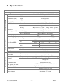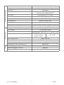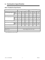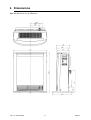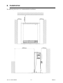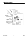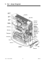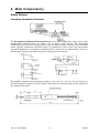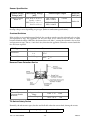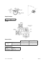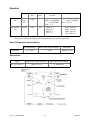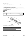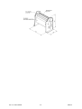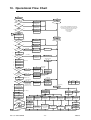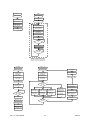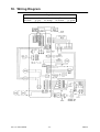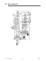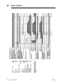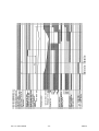
1
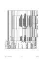
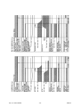
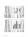
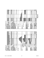
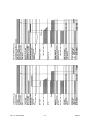
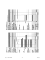
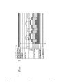
SERVICE MANUAL
RCE-460PTR
RCE-560PTR
FAN CONVECTOR
Proudly a member of The Australian Gas Association.
All of our products are AGA tested and approved.
Distributed and serviced in Australia under a
Quality System certified as complying with ISO
9002 by Quality Assurance Services.
Rinnai New Zealand has been certified to ISO 9001
Quality Assurance by Telarc.
Comparative Energy Consumption tested to The
Australian Gas Association requirements of
Australian Gas Code AG 103. An energy rating of
5 stars refers to an efficiency of approximately 80%,
that is, 80% of gas consumed is converted to useful
heat.
The Regulatory Compliance Mark (RCM)
indicates compliance with electrical safety
regulations in Australia and New Zealand
Rinnai Australia Supplier Code 5109
ISO 9001
ISO 9002
AG 103
Model for Quality Assurance in design/development, production, installation and servicing,
aimed primarily at achieving customer satisfaction by preventing nonconformity at all stages
from design through to servicing.
Same as ISO 9001 but excluding design.
Approval requirements for gas heaters as set by The Australian Gas Association and Australian
Liquefied Petroleum Gas Association Ltd, to ensure proper safety performance and quality levels
are achieved.
Convector RCE470/670TRE
© Copyright Rinnai Australia Pty Ltd
A.C.N. 005 138 769 All rights reserved
Produced by Customer Technical Services
February 2000
No portion or part of this manual may be copied without prior permission from Rinnai Australia.
Rinnai Australia takes no responsibility for the accuracy or otherwise of information contained in
this manual, and reserves the right to make modifications and change specifications without notice.
Key to Warning Symbols
Failure to comply with the following instructions may result in serious
personal injuiry or damage to the appliance.
Be careful of possible electric shock. Wiring inside this appliance may
potentially be at 240 Volts.
Remove the plug from the source when carrying out any of the following
activities.
Read Fault Diagnosis and Wiring Diagram carefully to avoid incorrect wiring
Do not disassemble. Parts within cannot be exchanged or diagnosed faulty.
Please follow instructions from page 47 carefully to ensure safe and appropriate service.
After completing the service and confirming that there are no water or gas leaks or
incorrect wiring, test operation of unit according to the Customer Operating Instructions.
After confirming normal operation, explain what was serviced to the customer and
operation principles if necessary.
This manual has been compiled by Rinnai Australia Customer Technical Services. While many
individuals have contributed to this publication, it will be successful only if you - the reader and
customer - find it useful. We would like to extend an invitation to users of this manual to make
contact with us, as your feedback and suggestions are valuable resources for us to include as
improvements. Rinnai are constantly working toward supplying improved appliances as well as
information, and specifications may be subject to alteration at any time.
SRV460/560
Issue No1
Table of Contents
Glossary of Terms ..................................................................................................... v
1. Introduction .............................................................................................................. 1
2. Specifications ............................................................................................................ 2
3. Combustion Specification ....................................................................................... 4
4. Dimensions ............................................................................................................. 11
5. Installation .............................................................................................................. 12
6. Schematic Diagram ............................................................................................... 13
7. Cut - Away Diagram ............................................................................................. 14
8. Operation Principles .............................................................................................. 15
9. Main Componentry ............................................................................................... 19
10. Operational Flow Chart ...................................................................................... 25
11. Error Code Messages .......................................................................................... 27
12. Diagnostic Points ................................................................................................. 34
13. Fault Finding Procedure ...................................................................................... 36
14. Fault Analysis ....................................................................................................... 39
15. Gas Conversion ................................................................................................... 45
16. Gas Pressure Setting Procedure ......................................................................... 46
17. Dismantling for Servicing ................................................................................... 47
18. Wiring Diagram ................................................................................................... 55
19. Block Diagram ..................................................................................................... 56
20. Time Charts ......................................................................................................... 57
21. Parts List ............................................................................................................... 66
22. Exploded Diagrams ............................................................................................. 72
Convector 460/560PTR
©Rinnai
Glossary of Terms
This glossary of terms and symbols is provided to assist you in understanding some of the language
used throughout this manual.
dB(A)
-
sound pressure level in decibels, “A” range
DC
-
direct current
AC
-
alternating current
Hz
-
Hertz
IC
-
integrated circuit
kcal/h
-
kilocalorie per hour
kPa
-
kilopascals
LED
-
light emitting diode
mA
-
milliamps
MJ/h
-
megajoule per hour
mm
-
millimetres
OHS
-
overheat switch
PCB
-
printed circuit board
CPU
-
central processing unit
POT
-
potentiometer
rpm
-
revolutions per minute
SV
-
solenoid valve
ø
-
diameter
∆ °C
-
temperature rise above ambient
POV
-
modulating valve
TH
-
thermistor
Convector 460/560PTR
-v-
©Rinnai
1. Introduction
Development Background
Rinnai have developed a Portable Convector/Air Purifier Space Heater with an air purifying
capacity that exceeds existing models and meets recent aims to improve health. We recommend that
replaceable parts and the location of the unit be changed yearly.
Features
• Air Purifier
1. Removes cigarette smoke, pollen, household dust and other micro-particles.
2. Use of the anti-bacterial and deodorising filter creates a comfortable space to live in (filter
indicator shows when it needs to be replaced.).
3. The dust sensor shows how clean the air is in a room.
4. The automatic function changes its operational level according to the cleanliness of the air in
the room. There are four levels of adjustment for manual operation.
5. The OFF Timers can be set in three steps.
• Heater
1. The various safety devices, fault history display, etc. are the same as the existing models.
2. “TR” model features dual ON/OFF Timer, remote control, economy mode, clock display &
child lock.
Convector 460/560PTR
-1-
©Rinnai
2. Specifications
Model No.
RCE - 460 PTR
Name of appliance
Portable Convector
Output
Main Unit Specifications
Dimensions (mm)
RCE - 560 PTR
5.5~18MJ/h (5.0 kW)
Width
520
Depth
210 (base 305)
Height
650
Weight (Kg)
Connections
16.2
Electrical
AC240V 50Hz (NZ : AC 230V)
Gas
Approved gas hose
Heating
Electrical
Consumption (W)
High: 38 Low :31 (NG)
High: 39 Low :31 (NG)
30 (Propane)
30 (Propane)
Air Purifying
Boost:27 High:22 Med:21 Low:20
Heat & Air Purifying
Max:56 Min:41 (5 on standby)
Heating Capacity
45m3
52.5m3
Air Purifying Capacity
45.6 m3
Comb. Specifications
Gas Type
Gas Input (MJ/h)
460PTR
NG
LPG
Main Burner
Heater Specifications
18
HI
21
LO
5.5
LO
5.5
HI
18
HI
21
LO
6
LO
6
Bunsen type
#30 Mesh
Operation
Push Button
Ignition method
Gas flow control
Continuous spark, Main Direct Ignition
(Low-approx.10 ° C)16~26 ° C(High-Continuous High)
High~Low (Modulating Control) 12-step automatic
changeover
Warm Air Outlet
Bottom front of unit
Air Volume (m3/min)
Air Flow Changeover
460PTR: 2.5~3.5
560PTR: 2.5~3.9
High ~ Low (12 step automatic changeover)
Line flow type ø 110x 328L
Convection Fan
Convection Fan Motor
Condensor line 4 pole motor
Filter Indicator
Convector 460/560PTR
HI
Slit type
Method
Room temperature
Control
560PTR
Form
Air Filter
Operation
5.5~21MJ/h (5.81 kW)
Thermistor 65 ° C ON
-2-
©Rinnai
Air Purifier
Filter method (initial efficiency approx. 80%)
Air Purifier Specification
Anti-bacteria
Activated Carbon (initial efficiency approx. 75%)
Operation
Operation Changeover
Push button
Automatic Operation (High/Med/Low) and Manual
Operation (Boost/High/Med/Low)
OFF Timer
3 step changeover (1, 2, 4 hour)
Louvre Location
Top of appliance
Airflow (m3/min)
Air Purifier Fan
Boost 3.3, Hi 2.2, Med 1.8, Lo 1.4
Sirocco Fan φ 160 x 80L
Condensor line 4 pole motor
Air Purifier Fan Motor
Dust Sensor
Particle Counter (scattered light method)
Safety Devices
Filter Replacement Indicator
Calculated as on page 18
Incomplete Combustion Device
Thermocouple method
Flame Failure
Thermocouple method
Reverse Flame Device
Overheat Device
Bi-metal method OFF 150 ± 5 ° C ON 125 ± 10 ° C
Thermistor
Thermal fuse
level 4~12 70 ° C
216 ° C OFF
level 1~ 3 70 ° C
Power Failure Device
Within PCB unit
Tilt Switch Device
Steel Ball Method (within PCB unit)
Over-current Protection
3-amp fuse
Other
Loose Primary Filter Detection Device
Micro-switch
Available gas types
NG, LPG
Electrical Frequency Converter
50Hz only
Replacement Filter
Convector 460/560PTR
HEOT - 003
-3-
©Rinnai
3. Combustion Specification
Basic Combustion Specification
Rinnai model reference
RCE-460PTR
Gas type
Gas consumption (MJ/h)
NG
NG
Propane LPG(NZ)
18
18
18
21
21
21
Low
5.5
6
6
5.5
6
6
φ 2.15
φ 1.40
φ 1.40
φ 2.15
φ 1.40
φ 1.40
A
1
1
1
1
1
1
B
0
0
0
0
0
0
*B
0
0
0
0
0
0
φ 20
φ 22
φ 22
φ 20
φ 22
φ 22
High
0.65
1.46
1.46
0.85
1.91
1.91
Low
7
18
18
7
18
18
X3C
X3P
X3P
X3C
X3P
X3P
Restrictor
Regulator pressure (kPa)
Propane LPG(NZ)
High
Main injector size
Thermocouple spacer
RCE-560PTR
Burner marking
Combustion method
Bunsen burner
Burner type
Slit
Solenoid valve
Direct Single Seated Valve Type
Modulating solenoid valve
Rinnai Electronic Control
* Level decided by gas type setting.
Convector 460/560PTR
-4-
©Rinnai
Warm Air Discharge Temperature Distribution - 560PTR (Heater)
Conditions:
<High Combustion>
Test gas:
Measured Input:
Nominal Input:
Natural
20.90 MJ/h
21.00 MJ/h
4,990 kcal/h
5,020
(Unit ∆°C)
56
75
76
72
75
68
61
61
70
82
75
80
85
78
61
72
56
81
71
81
94
85
61
74
60
80
66
79
90
86
61
74
54
77
64
79
89
87
58
71
(Average 73.1)
(Room temperature 26.0°C)
Conditions:
<Low Combustion>
Test gas:
Measured Input:
Nominal Input:
Natural
5.40 MJ/h
5.50 MJ/h
1290 kcal/h
1310
(Unit ∆°C)
22
26
27
26
26
25
24
23
25
30
27
28
31
29
24
28
22
31
27
30
36
32
24
29
23
32
27
33
39
34
24
29
22
33
27
33
41
35
23
29
(Average 28.4)
(Room temperature 26.0°C)
Convector 460/560PTR
-5-
©Rinnai
Warm Air Discharge Velocity - 560PTR (Heater)
<High>
(Unit m/sec)
2.91
2.91
3.31
3.99
3.46
2.79
2.76
1.88
3.39
3.52
3.67
4.31
4.13
3.34
3.12
1.64
3.53
3.94
4.29
4.29
4.30
3.77
3.61
2.58
3.87
4.40
4.19
4.23
4.76
4.09
3.48
3.16
4.34
4.28
3.83
4.96
4.61
4.60
3.40
3.45
(Average 3.68)
<Low>
(Unit m/sec)
1.54
1.72
1.87
2.68
1.67
1.49
1.86
1.17
2.22
2.41
2.39
2.62
1.98
1.84
2.35
1.08
2.12
2.64
2.60
3.14
2.77
2.50
2.41
1.63
1.68
1.95
2.37
3.10
3.04
3.10
2.10
2.30
3.02
2.89
2.41
3.10
3.11
2.96
2.30
2.54
Conditions
Convection Fan rpm
(Average 2.32)
High: 840 rpm
Low: 550 rpm
Measured at full combustion
Average air velocity on High: 3.68 m/sec
Average air velocity on Low: 2.32 m/sec
Area of louvre: 0.018 m²
Air flow rate on High: 3.97 m³/min
Air flow rate on Low: 2.51 m³/min
Convector 460/560 PTR
-6-
©Rinnai
Warm Air Discharge Temperature Distribution - 460PTR (Heater)
Conditions:
<High Combustion>
Test gas:
Measured Input:
Nominal Input:
Natural
18.10 MJ/h
18.00 MJ/h
4,320 kcal/h
4,300
(Unit ∆°C)
53
67
68
63
65
63
55
54
63
74
66
69
71
72
54
65
52
74
62
69
79
79
55
65
53
74
58
70
78
82
54
67
52
72
56
69
80
85
51
66
(Average 65.6)
(Room temperature 26.0°C)
Conditions:
<Low Combustion>
Test gas:
Measured Input:
Nominal Input:
Natural
5.40 MJ/h
5.50 MJ/h
1290 kcal/h
1310
(Unit ∆°C)
22
26
27
26
26
25
24
23
25
30
27
28
31
29
24
28
22
31
27
30
36
32
24
29
23
32
27
33
39
34
24
29
22
33
27
33
41
35
23
29
(Average 28.4)
(Room temperature 26.0°C)
Convector 460/560PTR
-7-
©Rinnai
Warm Air Discharge Velocity - 460PTR (Heater)
<High>
(Unit m/sec)
2.58
2.58
2.93
3.53
3.07
2.47
2.44
1.66
3.00
3.12
3.25
3.81
3.66
2.96
2.76
1.45
3.13
3.49
3.80
3.80
3.80
3.34
3.20
2.29
3.43
3.89
3.71
3.74
4.22
3.62
3.08
2.80
3.84
3.79
3.39
4.39
4.08
4.08
3.01
3.06
(Average 3.26)
<Low>
(Unit m/sec)
1.54
1.72
1.87
2.68
1.67
1.49
1.86
1.17
2.22
2.41
2.39
2.62
1.98
1.84
2.35
1.08
2.12
2.64
2.60
3.14
2.77
2.50
2.41
1.63
1.68
1.95
2.37
3.10
3.04
3.10
2.10
2.30
3.02
2.89
2.41
3.10
3.11
2.96
2.30
2.54
Conditions
Convection Fan rpm
(Average 2.32)
High: 800 rpm
Low: 550 rpm
Measured at full combustion
Average air velocity on High: 3.26 m/sec
Average air velocity on Low: 2.32 m/sec
Area of louvre: 0.018 m²
Air flow rate on High: 3.52 m³/min
Air flow rate on Low: 2.51 m³/min
Convector 460/560 PTR
-8-
©Rinnai
Air Discharge Velocity (Air Purifier) 460/560PTR
<Boost>
(Unit m/sec)
1.42
1.57
1.27
1.24
2.43
3.73
2.76
1.56
2.73
4.05
4.73
4.13
4.80
4.20
4.90
3.41
4.62
5.30
(Avg 3.27)
<High>
(Unit m/sec)
0.73
0.96
0.96
2.08
1.95
2.62
1.38
1.21
1.80
2.44
3.00
3.09
3.08
2.77
2.84
1.93
2.73
3.13
(Avg 2.15)
<Medium>
(Unit m/sec)
0.57
0.78
0.82
1.88
1.50
1.99
1.57
1.03
1.38
1.85
2.53
2.71
2.72
2.25
2.37
1.77
2.29
2.63
(Avg 1.81)
<Low>
(Unit m/sec)
0.47
0.72
0.82
1.57
1.36
1.48
1.19
0.88
1.28
1.28
1.94
2.33
2.20
1.90
1.89
1.54
1.93
2.00
Conditions
(Avg 1.49)
Air Purifier Fan rpm Boost: 1100 rpm
High: 740 rpm
Med: 670 rpm
Low: 600 rpm
Average air velocity on Boost: 3.27 m/sec
Average air velocity on High: 2.15 m/sec
Average air velocity on Med: 1.81 m/sec
Average air velocity on Low: 1.49 m/sec
Area of louvre: 0.0165 m²
Air flow rate on Boost: 3.24 m³/min
Air flow rate on High: 2.13 m³/min
Air flow rate on Med: 1.80 m³/min
Air flow rate on Low: 1.47 m³/min
Convector 460/560PTR
-9-
©Rinnai
Noise Level - 460/560PTR
Heater
Operation Noise (dB (A))
High: 41
Low: 27
Measuring method: According to Japanese Industry Standards
During Combustion
Air Purifier
Operation Noise (dB (A))
Boost: 45
High: 35
Med: 31
Low: 27
Measuring method: According to JEM1467
Convector 460/560 PTR
- 10 -
©Rinnai
4. Dimensions
Note: All dimensions are in millimetres
Convector 460/560PTR
- 11 -
©Rinnai
5. Installation
The following clearances are recommended for installation.
Convector 460/560PTR
- 12 -
©Rinnai
6. Schematic Diagram
Convector 460/560PTR
- 13 -
©Rinnai
7. Cut - Away Diagram
Convector 460/560PTR
- 14 -
©Rinnai
8. Operation Principles
Control Panel Layout
Convector 460/560PTR
- 15 -
©Rinnai
Normal Heater Operation
• Press the Heat ON / OFF button.
• The ON/Combustion indicator illuminates green, and the convection motor starts
pre-purging.
• The Digital Display displays the present room temperature. After approximately 3 seconds, the
electrode starts discharging electricity, and at the same time, the solenoid valves and the
modulating valve open. After ignition, while the main burner is on “High”, the ON/Combustion
indicator illuminates red when the thermocouple detects the flame, and electrical discharge
ceases. (Forced combustion is carried out for approx. 60 sec on High).
• The PCB’s micro-computer regulates the room temperature and combustion time, and also controls both using fuzzy logic until the preset room temperature is reached.
Temperature Control
• Room temperature can be adjusted as desired with the Temp / Time buttons.
Turning OFF the Heater
•
•
•
•
Press the Heat ON / OFF button.
The solenoids and modulating valve close and combustion ceases.
The indicators will go out. (The digital display will show the present time.)
The convection motor stops after post-purging (2~4 minutes).
Child Lock
• Press the Up and Down buttons simultaneously. The Child Lock indicator will illuminate.
• When setting the lock while heater is operating, only the Heat ON/OFF button responds. When
unit is off, the Heater ON /OFF button will not respond. (The Air Purifier can be operated.)
• The Up and Down buttons should be pressed simultaneously for approximately 2 seconds to
cancel the Child Lock.
Clock Setting
• Press the Set Times button once. The Clock indicator will flash.
• Press the Temp/Time buttons to adjust the time.
• Press the Set Times button five times to set the clock. The indicator will go out.
Setting Timers 1 and 2 (Heater)
•
•
•
•
•
Press the Set Times button twice. Timer 1 “on” indicator will flash.
Press the Temp/Time buttons to adjust to the starting time.
Press the Set Times button again. The Timer 1 “off” indicator will flash.
Press the Temp/Time buttons to adjust to the finishing time.
Press the Set Times button three times to lock in the programmed times. The Digital Display will
show the current time. (The Timers can also be set during heater operation. In this instance,
combustion will cease and the Timer will go into stand-by mode. When in stand-by mode, the
set room temperature for the Timers cannot be modified. In order to modify the set room
temperature, revert the unit to its normal state, modify the set room temperature and press the
Timer button to complete setting.)
• The intelligent function will start the unit so that the room is warm at the set time.
• The Timer operates for the set time then automatically stops. (The Timer indicator starts flashing
5 minutes before the unit ceases operation and continues to flash after operation has ceased.)
• If the same button is pressed twice when the Timer is in stand-by mode, the unit will go into
normal OFF mode.
Convector 460/560PTR
- 16 -
©Rinnai
• If the Heater button is pressed when the Timer is in stand-by mode or during combustion, the
unit will go into normal OFF mode.
Automatic-Economy Mode (Heater)
30 minutes after the present room temperature has reached
the set room temperature, the Economy function will start
operating automatically and the Economy indicator will
illuminate.
•After a room reaches the set temperature, the set room
temperature will decrease 3 times automatically, each
time dropping by a maximum of 1 ° C in 30 minute
intervals.
•If the set room temperature is “L”, “16”, “26” or “H” a
few minutes after operation has commenced, the autoeconomy function will not activate and the Economy indicator will not illuminate. (However,
once the auto-economy function has commenced, the unit will continue to operate in that mode
if set to the above temperatures.)
• The increments shown in the table below are based on a temperature gradient which is
calculated using the initial room temperature 1 minute after ignition, and the room temperature
5 minutes after ignition. (This is for when the room temperature is set between 17~25 ° C.)
Initial Room Temperature
Increment ( ° C)
Temperature
Gradient
<6.0 ° C
>6.0 ° C
<16.0 ° C
>16.0 ° C
<6.0 ° C
0.3 ° C
0.7 ° C
1.0 ° C
6.0 ° C~8.0 ° C
0.7 ° C
0.7 ° C
1.0 ° C
>8.0 ° C
0.7 ° C
0.7 ° C
0.7 ° C
• Even if the set room temperature is modified while auto-economy is operating, the autoeconomy function will continue.
• When the present room temperature is over 5 ° C less than the set room temperature while autoeconomy is operating, the auto-economy function will go into stand-by mode. (The Economy
indicator will go out.)
The comfort control alters combustion and fan speed more frequently to counteract the feeling of
cold air and activates at the 2nd phase of auto-economy operation, preventing discomfort from
overcooling and saving energy.
• The comfort control pattern is determined from within the PCB.
• Like auto-economy, the comfort control does not activate when the set room temperature is “L”,
“16”, “26”, or “H”.
• During comfort control when the present room temperature is at least 5 ° C less than the set room
temperature, the comfort control will end and the auto-economy function will go into stand-by
mode. (The Economy indicator will go out.)
Convector 460/560PTR
- 17 -
©Rinnai
Automatic Air Purifier Operation
1. Turning ON
i) Press the “Air Purif” button. The Fan Speed “Auto” indicator will illuminate and the Air Purifier
fan will rotate on High. The Dust Indicator will illuminate green.
ii) After approximately 20 seconds, the fan speed will adjust automatically according to the
cleanliness of the air. (The Air Purifier fan will operate at levels High, Med, and Low.) The 3 dust
indicators will illuminate according to the degree of uncleanliness of the air in a room. (Red =
Exceedingly High, Orange = High, Green = Low.)
2. Adjusting the Fan Speed
i) Adjust to the desired Fan Speed with the Fan Speed button.
3. Turning OFF.
i) Press the “Air Purif” button.
ii) The Air Purifier Fan will stop.
iii) The Fan Speed changeover indicator and Dust Indicator will go out.
OFF Timer (Air Purifier)
• Press the OFF Timer button when the Air Purifier is operating and set the desired time (1, 2, or 4
hours).
• The Air Purifier will turn off after the set time period is lapsed.
Filter Replacement Indicator
When the air purifier has operated for 4000 hours, the filter replacement indicator (Purif Filter Chg)
will illuminate to let you know that the filter needs to be replaced. The operation time is calculated
as follows:
Air Cleaning Operation Time = 1/2 (Hours of automatic operation) + Hours of manual operation
The Reset Button - the filter replacement indicator must be reset by doing the following:
• When the “Purif Filter Chg” indicator is illuminated:
Press the reset button continuously for approximately 3 seconds to make the indicator go out and
to reset the hours of air purifier operation.
• When the “Purif Filter Chg” indicator is out:
Press the reset button continuously for approximately 3 seconds to illuminate the indicator
momentarily (for 0.5 sec) and to reset the hours of air purifier operation.
Convector 460/560PTR
- 18 -
©Rinnai
9. Main Componentry
Safety Devices
Incomplete Combustion Prevention
The Incomplete Combustion Prevention Device senses flame temperature using a sensor with a
thermocouple. Thermocouples are widely used as burner safety devices. The Incomplete
Combustion Safety Device is incorporated in a special burner structure connected to an electronic
sensor. Ignition, combustion and flame failure are monitored by this system, and main burner
abnormal combustion or incomplete combustion due to unclean air are electronically sensed as a
thermocouple change from flame temperature change prior to occurence.
The amplifier amplifies the thermocouple output by a few volts (20 ~ 30 m V) and any changes are
checked against the comparator. If the output is lower than the standard voltage of the comparator,
the solenoid valve closes.
Convector 460/560PTR
- 19 -
©Rinnai
Sensor Specification
Ignition Sensing
Voltage (mV)
ODS Sensing Voltage
(mV)
Output at initial
check +2
NG: level 4~12 14 ± 1.5
level 1~3 14 ± 1.5
LPG: level 4~12 16 ± 1.5
level 1~3 16 ± 1.5
Thermocouple Output
NG: >18mV
LPG: >20mV
<35mV
NG: >18mV
LPG: >20mV
<35mV
Drop Out
Time (sec)
Below 60
“Drop Out” = Time until the gas is cut off after flame failure.
Sensing voltage varies depending on gas type. (Refer to combustion specifications)
Overheat Switches
If the air filter or air outlet becomes blocked, the overheat switch causes the solenoid valve to close
and operation to stop. The appliance can be re-lit when it has cooled. If the air filter or outlet
becomes blocked and the OHS fails, the thermal fuse will “blow”, causing the solenoid valve to close
and operation to stop. This is a “one-shot” fuse; therefore the appliance cannot be restarted until this
fuse has been replaced.
OHS Type
Characteristics
Thermistor
level 4~12
1~3
Operates at
70 ° C
Thermal Fuse
Cut Off Temp
216 ±
0
10
°C
Reverse Flame Detection Device
Type
Reserve Flame
Detection Switch
(Bi-metal)
Characteristics
Operational
Temp.
150 ± 5 ° C
OFF
Reset Temp.
125 ± 10 ° C
ON
Tilt Switch Safety Device
Normally, the tilt circuit is open, but the steel ball rolls when the unit is tilted, closing the circuit.
Steel Ball Tilt Switch
Convector 460/560PTR
50° ~ 80°
Activating Angle
- 20 -
©Rinnai
Surge Protection
Glass Fuse
3 Amp
Valves
Solenoid Valve
Solenoid Valve 1
Single Seated
Valve
Solenoid Valve 2
Voltage
DC90 V
DC 90V
Power Consumption
Below 5 W
Below 5 W
Modulating Valve
Voltage
<200mA
Consumption
Below 1 W
Convector 460/560PTR
- 21 -
©Rinnai
Electrical
Type
Diameter
(mm)
Width
(mm)
Air flow Rate
m3/min
Fan (rpm)
Convection
Fan
Line
Flow
Fan
φ 110
328
(Full Combustion)
High: 3.5(460PTR),
3.9(560PTR)
Low: 2.5
High: 800 ± 70 (460PTR)
840 ± 70 (560PTR)
Low: 550 ± 70
Air Purifier
Fan
Sirocco
φ 160
80
Boost: 3.3
High: 2.2
Med: 1.8
Low: 1.4
Boost: 1100 ± 100
High: 740 ± 100
Med: 670 ± 100
Low: 600 ± 100
Note: Air flow rate is measured using a duct.
Fan speed is measured using a finished product during air purifier operation.
Room Temperature Control Device
Thermistor
Set Temp Range
Room Temp Display Range
Differential
16 ~ 26oC
1 ~ 30oC
Approx. 0.5oC
Dust Sensor
Input
Detectable Particle Diameter
Detectable Density Range
AC 5V & DC 5V
approx. >1 µ m
0~8000/0.01f3
Convector 460/560PTR
- 22 -
©Rinnai
Operating Principles
1. An air current is created by the heat generated from heater resistance guiding the surrounding
unclean air into the area where the detector is.
2. The lens projects infra-red light around the detector.
3. When dust passes through the detector area, infra-red light is scattered, and the sections of scattered light are gathered with the lens into the Photo Tr.
4. The Photo TR converts scattered light into electrical signals. The signal is then processed within
the circuit emitting a dust signal.
Combustion
Burner
Type
Combustion Type
Burner Port Shape
Qty
Material
Main burner
Bunsen
Slit
1
Heat Resistant
Stainless Steel
Combustion Chamber (Combustion Box)
Material
Thickness (mm)
SA1D-40
0.6
Heat Resistant Stainless Steel
0.5
Convector 460/560PTR
- 23 -
Dimensions
As below
©Rinnai
Convector 460/560PTR
- 24 -
©Rinnai
10. Operational Flow Chart
Heater ON
Cause eliminated
Power Point ON
No
I
73
No
II
71
Operation/Comb.
Ind. flashes (red)
Yes
No
ON/OFF SW.
Normal
1
Power Point OFF
Operation/Comb.
Ind. flashes (red)
Yes
I: Micro-computer and E2PROM's signal path normal
II: Solenoid valve and Modulation valve rotation normal
III: Gas disconnection device normal when tilting
C.M.: Convection Motor
R.F.: Reverse Flame
SV: Solenoid
70
Operation/Comb.
Ind. flashes (red)
Yes
ON/OFF sw. ON
A
Operation/Comb. Ind.
Illuminates (Green)
All indicators OFF
Display time6Room temp.
14
R.F detection
sw.temp. fuse
Normal
2
No
Yes
Filter Ind. flashes
No
3
III
4
T/C output
<10mV
5
Conv. motor Hi ON
6
Fan motor
>6 r.p.m
03
Operation/Comb.
Ind. flashes (red)
Yes
No
Operation/Comb.
Ind. flashes (red)
(After a max. of 50 sec)
(a)
No
(10 sec after (a))
7
Sparker ON
8
Solenoid SV1 ON
8
Solenoid SV2 ON
9
POV Med ON
10
Overheat TH
Normal
C.M. OFF
62
Operation/Comb.
Ind. flashes (red)
Yes
Conv. motor Lo ON
C.M. OFF
72
C.M med ON
Yes
5
ON/OFF Switch OFF
Operation/Comb.
Ind. flashes (red)
(After max.255 sec)
C.M. OFF
(After 0.2 sec)
(b)
33
No
Sparker OFF
Yes
(Disconnection)
(Short circuit)
34
C.M. med ON
Operation/Comb.
Ind. flashes (red)
SV1,SV2 OFF
POV OFF
11
Room Temp.
Thermistor
Normal
No
32
Yes
9
(after approx. 3 sec.)
POV Hi ON
T/C output
(Ú1mV)
Operation/Comb.
Ind. flashes (red)
(After 5 sec)
Conv. motor OFF
Sparker OFF
(c)
Ú1 Igniton sensed
output is the initial T/C
check output +2mV
(min.3mV. max. 18mV)
Operation/Comb. Indic.
Illuminates (Red)
(Disconnection)
(Short circuit)
(30 sec. after (b))
No
Yes
5
31
Sparker OFF
11
C.M. med OFF
Operation/Comb.
Ind. flashes (red)
SV1,SV2 OFF
*
NG
PROP.G
LPG
14mV
16mV
16mV
POV OFF
(150~255 sec)
Conv. motor OFF
Conv. motor med ON
Sparker OFF
Conv. motor Hi ON
5
SV1, SV2 OFF
(10 sec. after (c))
Temp. check starts
5
C.M. Mod. control
9
M.V modulating. control
OH Thermistor
activates (65EC)
No
B
POV OFF
C.M Med ON
14
03
12
16
70
62
00
Operation/Comb.
Ind. flashes (red)
Operation/Comb.
Ind. flashes (red)
Operation/Comb.
Ind. flashes (red)
Operation/Comb.
Ind. flashes (red)
Operation/Comb.
Ind. flashes (red)
Operation/Comb.
Ind. flashes (red)
Filter Ind. flashes
Rev. flame detection
sw. OFF (150EC)
2
Thermal fuse
discon. (216EC)
Yes 10
OH thermistor
activated (70EC)
Filter indicator flashes
Safety device
activated
SV1, SV2 OFF
C.M. med ON
Operation/Comb.
Ind. flashes (red)
2
Yes
M.V POV OFF
Re-instatement
of power
12
3
Gas disconn. device
when tilting is
activated (50~80EC)
Incomplete comb.
prevention safety
device is activated
(*mV, 5 sec)
11
OFF Function act.
>40EC 10 min
1
ON/OFF switch
Error (for 15 sec)
12
Operation ceases
Fan motor error
<350rpm, 4 sec)
Power failure
No
Convector 460/560PTR
- 25 -
©Rinnai
Heater OFF
TIMER
ON/OFF Switch OFF
ON/OFF switch ON
Combustion A -> B
Display
Room Temp. 6Time
Timer switch ON
All Indicators OFF
SV1 SV2 OFF
Mod. valve OFF
C.M. (med) ON
Display
Room Temp. 6Time
C.M. OFF
Operation/comb. Ind.
illuminates (Green)
(150~255 sec)
SV1 SV2 OFF
POV OFF
C.M. (med) OFF
Timer Ind. illuminates
C.M. OFF
No
Pre-heat
time
Yes
Combustion A -> B
Timer Indicator flashes
Timer off
set up time
No
Yes
*When Timer 1 or Timer 2 is set up, the heater
will operate 1 cycle per day. (Within dotted line)
Then Timer 1 and Timer 2 are set up, the heater
will operate 2 cycles per day. (Within dotted line)
OFF TIMER
Air Purifying ON
ON/OFF switch ON
ON/OFF switch ON
Cause elimated
Air volume indicator
illuminates (auto)
Air volume indicator
illuminates (auto)
All indicators OFF
Dust indicator
illuminates (Green)
Dust indicator
illuminates (Green)
Air Purification
motor Hi ON
Air Purification
motor Hi ON
14
ON/OFF switch OFF
OFF timer switch ON
Automatic
operation
OFF Timer indicator
illuminates (1 hour)
No
Air purification motor OFF
Dust indicator OFF
Yes
OFF timer sw. change
Set up time
has passed
No
Dust Ind.
illuminates (Green)
Dust Ind.
lluminates (Orange)
Dust Ind.
illuminates (Red)
Air Purificaiton
motor Lo ON
Air Purificaiton
motor med ON
Air Purificaiton
motor Hi ON
Operation ceases
Air Purifying OFF
ON/OFF Switch OFF
Air volume ind
Lo-Med-Hi-Boost
05
Air purification motor
Lo-Med-Hi-Boost
15
Yes
Air volume indicator OFF
Operation/combustion
indicator flashes (Red)
Dust indicator
Green-orange-Red
16
Safety device
activated
Pre-filter comes off
detection
Yes
No
Air volume Ind. OFF
Dust indicator OFF
Air Purification motor
OFF
Convector 460/560PTR
- 26 -
©Rinnai
11. Error Code Messages
Error Code Messages
Error
Code
Content
Diagnostic Check Point
00
Power re-instatement while ON/OFF switch ON
-
03
Gas interrupted due to Tilt Switch activation
Check Tilt Switch
05
Detection of Loose Primary Filter
Check Primary Filter
11
Mis-ignition
Check Thermocouple Output
12
Incomplete Combustion Activation
Flame Failure
Check Thermocouple Output
14
Overheat Thermistor Activation
Check Overheat Thermistor
14
Reverse Flame Safety Device
Check Reverse Flame Sensor
Switch
14
Thermal Fuse Melted
Check Thermal Fuse
16
High Temp. Cut off (10 minutes at > 40 ° C)
Check Room Temperature
Thermistor
31
Room Temperature Thermistor broken circuit
Check Room Temperature
Thermistor
32
Room Temperature Thermistor short circuit
Check Room Temperature
Thermistor
33
Overheat Thermistor broken circuit
Check Overheat Thermistor
34
Overheat Thermistor short circuit
Check Overheat Thermistor
62
Faulty Fan Motor rpm
Check Convection Fan Motor
70
Heater ON/OFF switch abnormal
Check Control PCB
(ON/OFF Switch)
71
Solenoids or modulating valve circuit abnormal
-
72
Thermocouple initial value abnormal
Check Thermocouple output
72
Thermocouple high cut-out
(> 48mV for 5 secs)
Check Thermocouple output
73
Communication Error between PCB & E2PROM
-
* If the safety devices activate while either (or both) the heater and air purifier are operating, both
will cease operating.
* When the unit is off, press the “override” and “∨” buttons simultaneously for at least 2.5 seconds
to display the following at 2.5 second intervals in this order:
Error History (No. 1 (most recent) ~ No. 5);
Estimated Combustion Time (x100H);
Combustion Frequency (x100 times);
Estimated Air Purifier Operation Time (x100H); and
Actual Air Purifier Operation Time (x100H).
* When the unit is off, press the “override” and “∧” and “∨” buttons simultaneously for 2.5 seconds
to reset Error History and Actual Air Purifier Operation Time.
Convector 460/560PTR
- 27 -
©Rinnai
Memory Function for Maintenance Data
The 5 most recent error messages and the estimated time of combustion, combustion frequency,
estimated time of air purifier operation, and air purifier operation time are stored, as well as E2
PROM.
<How to recall data>
While the unit is off, press the “override” and “∨” buttons simultaneously for at least 2.5 seconds to
bring up the error history on the display. The error history will display the following in a 2.5 second
cycle : the 5 most recent error messages (the most recent is No. 1; No.5 the oldest), estimated time
of combustion, combustion frequency, estimated time of air purifier operation, and air purifier
operation time.
Example.
Item
Digital Display
Error History
Comments
No. 1 (Latest Error)
Sudden Extinction
No. 2
Power Failure
No. 3
Mis-ignition
No. 4
Mis-ignition
No. 5
No error
Combustion Time
1300 hours
Not displayed if below 100 hours
Combustion Frequency
3700 times
Not displayed if below 100 times
Estimated Air Purifier Operation Time
5000 hours
Not displayed if below 100 hours
Air Purifier Operation Time
Note 1
5000 hours
Not displayed if below 100 hours
<How to Reset> (Same as Initialisation of E2 PROM)
• While the unit is OFF, press all three buttons “∧”, “∨”, and “override” simultaneously for at least
2.5 seconds.
• The digital display will go out, and “88:88” will be displayed when resetting has been completed, then “--:--” will be displayed.
(Additional combustion time, combustion rpm, and additional air purifier operation time will not be
reset.)
Note 1: This operation time will be displayed as the actual operation time after initialisation when
the reset button is pressed.
Convector 460/560PTR
- 28 -
©Rinnai
E2 PROM data will not be erased during a power failure. However, this data is divided into 2 groups
where one of the groups of data can be reset at the external control pads.
[Permanent Data]
• Modulating Valve Current Supplement
Value
• Fan Current Supplement Value
• Estimated Combustion Time
• Combustion Frequency
• Estimated Air Purifier Operation Time
[Deletable Data]
• Present Time
(Initial Setting)
( 0:00 AM)
•
•
•
•
•
(None)
( 6:00 AM)
( 6:00PM)
( 22 ° C)
( 0 Hours)
Error History
Timer 1 Time
Timer 2 Time
Set Room Temperature
Air Purifier Operation
Time
<Resetting>
Refer to “How to Reset” under “Memory Function for Maintenance Data”.
<Test Mode and Adjustable Mode>
There is a Test Switch on the PCB.
Test Switch
Normal OFF
Gas Conversion
Mode
If it is changed over to gas conversion mode while the unit is OFF and with the test button ON, the
present gas type code will be displayed.
The gas type code will change with the “∧” and “∨” temperature buttons.
a. When the “∨” button is pressed
“13” (NG)
“LP”
b. When the “∧” button is pressed.
“LP”
“13” (NG)
The gas type code will be stored in memory if the test button is pressed again.
Convector 460/560PTR
- 29 -
©Rinnai
Normal OFF
Test
Button
Low Pressure Mode
e
c
on ton
n
t
to
Bu
ut
1
B
er
st
imes High Pressure Mode
Te Tim
n two t
to
t
u
B
t
Tes
n
1 Butto
Timer
Test Mode
Test Bu
tton thr
ee time
s
Te
Timer
1 Butto
Decision Level
st
n
Bu
Adjustment
Mode
Ti
tto
m
n
er
1 B fou
rt
ut
im
to
es
n
Sensitivity
Selection Mode
The unit will go into Test Mode when the Test Switch is switched ON while the unit is operating.
The unit will go into each of the following modes during Test Mode : Low Pressure Mode, High
Pressure Mode, Decision Level Adjustment Mode, and Sensitive Selection Mode.
• Test Mode...................................................Disables the temperature controls and allows you to
change the level manually. (Cancels when the test
switch is turned on again, or when combustion ceases.)
The level can be raised/lowered with the temperature
control buttons “∧” and “∨”, however, if they are continuously pressed for at least 0.5 seconds, it will change
to level 12 or level 1.
• Low Pressure Mode...................................The modulating valve electric current value for low
combustion can be adjusted with the temperature “∧”
and “∨” buttons. After adjusting, the data will be stored
when Timer 1 is switched ON.
• High Pressure Mode .................................The modulating valve electric current value for high
combustion can be adjusted, with the temperature “∧”
and “∨” buttons. After adjusting, the data will be stored
when Timer 1 is switched ON.
• Decision Level Adjustment Mode ...........The maximum flame failure detection level can be
adjusted with the temperature “∨” button, and the minimum with the temperature “∧” button. They can be set
in the following order: 12mV, 14mV, 16mV, 18mV.
After adjusting, the data will be stored when Timer 1 is
switched ON.
• Sensitivity Selection Mode .......................The sensitivity can be changed over from 1 to 2, and
vice versa, with the temperature “∨” button. After
adjusting, the data will be stored when Timer 1 is
switched ON. It is factory set at sensitivity level 2.
* To reset each mode, press the ON/OFF button to turn the unit OFF.
* If the Timer 1 button is not pressed during each mode, the updated setting will be cancelled and
the data will not be stored in memory.
* If the data is stored, it will return to test mode and the entered information will be displayed.
Convector 460/560PTR
- 30 -
©Rinnai
<LED display during Test/Adjustment Mode>
1. During Gas Conversion Mode (left side of display)
Gas Type
NG
LPG
Gas Type Code
13
LP
Displayed
2. During Test Mode
The first and second digits of the LED display the level.
The third and fourth digits of the LED display the entered data.
The first and second digits will display:
5 second test delay
Level 1
Level 12
~
The third and fourth digits will display:
for no entry
for gas type
for low pressure
for high pressure
for standard
level
3. Low Pressure Mode
4. High Pressure Mode
Convector 460/560PTR
- 31 -
©Rinnai
5. Standard Level Mode
12mV
High
14mV
16mV
18mV
Low
A function called “factory mode”* has been added to confirm appliance settings.
*Displays set manufacturing values.
1. Operation Method
Press the “∧” button continuously, then the “Heat” button.
2. Display Contents
The set values for the Appliance Type Code, Gas Type Code, Flame Failure Detection Level, Dust
Sensor Level will be displayed in that order at 2.5 second intervals.
3. Display Contents Information
a. Appliance Type Code
RCE - 560 PTR
RCE - 460 PTR
b. Gas Type Code
For NG
For LP
c. Flame Failure Detection Level Values
12mV
Convector 460/560PTR
14mV
16mV
- 32 -
18mV
©Rinnai
An example of High Flame Failure Detection Level 12mV, and Low Flame Failure Detection
Level 18mV
d. Dust Sensor Level
Level 1
Level 2
e. Afterwards, it will revert back to the normal temperature display.
Convector 460/560PTR
- 33 -
©Rinnai
Flow Chart CN
No
1
Wire Colour
No
Measurement Value
Part
blue-blue
switch OFF: 90~100k Ω
ON: 10~30 k Ω
Heater Switch
<1 Ω
Thermal Fuse
B
16
G
2
17
white-white
38
G1
black-white
<DC 1V
<1 Ω
Reverse Flame
Sensor Switch
3
N
-
DC 4~6 V
Tilt Switch
4
E
black-white
<DC 10mV
Thermocouple
5
J
blue-yellow
black-white
6
7
8
D
GND
AC 45~90V
150~300 Ω
>6 rpm (0.4Hz)
DC 4~6V
K
white-white
AC 90 ~110V
K
brown-brown DC 80~100V
K1
brown brown
2.0~3.0k Ω
yellow yellow
K2
yellow-yellow 2.0 ~ 3.0k Ω
G
36-37
Hi~Lo DC 0.1~2.0V
16~26 Ω
10 ° C 115~135k Ω
20 ° C 70~85k Ω
40 ° C 25~40k Ω
G2
white-white
11
F
10 ° C 58~73k Ω
yellow-yellow 20 ° C 33~44k Ω
40 ° C 9~19k Ω
12
E
black-white
(NG) >DC 14mV
(LP) >DC 16mV
black-white
DC 1~4V
GND
>350 rpm (24Hz)
red-black
DC 3~8V
blue-yellow
AC 45~100V
60~150 Ω
14
D
H
Convector 460/560PTR
Convection Fan
Motor
Sparker
Solenoid Valve
10
13
Convection Fan
Motor
DC 1~4V
red-black
red-white
9
Hi~Lo
- 34 -
Modulating Solenoid
Valve
Overheat Thermistor
Room Temp.
Thermistor
Thermocouple
Convection Fan
Motor
Air Purifier Fan
Motor
©Rinnai
O
black-black
AC 3~7V
31 ~43 Ω
grey-black
DC 4~6V
1.8~2.2k Ω
15
P
grey-violet
16
C
white-white
Dust Sensor
Dust indicator colour
Voltage
green-orange
DC 0.8~2.2V
orange-red
DC 1.1~2.5V
<1 Ω (ON)
Micro-Switch
Wire Colour No.
Measurement Value
grey - grey
AC 207~264V
33~45 Ω
white - white
AC 90~110V
8~20 Ω
blue - blue
AC 8~12V
1~4 Ω
brown - brown
AC 8~12V
1~4 Ω
violet - voilet
AC 10~15V
0.5~2 Ω
black - black
AC 3~7V
0.5~2 Ω
!" ± ##"
Gas Type
High
Low
NG
800
550
LPG
870
480
NG
840
550
LPG
950
480
460PTR
560PTR
Convector 460/560PTR
- 35 -
©Rinnai
$%
%
&
'(
Service Call System
Check Points (No.’s refer to causes outlined in the following pages)
Appliance does not operate after • Check electrical cord is connected to the power point.
having pressed ON/OFF switch. • Confirm power supply.
(ON/Combustion indicator does • Check Function Lock (Indicator).
not illuminate green.)
Ignition does not occur.
(ON/Combustion Indicator
does not illuminate red.)
(Error code “11”)
•
•
•
•
No sparker noise even when
Heater ON/OFF button is
pressed
• This appliance uses a muted sparker and makes a different
sound to older units.
Auto-economy indicator does
not illuminate.
• This appliance has an auto-economy function which automatically starts operating (“Economy” indicator illuminates) 30
minutes after a room reaches the set temperature. However,
the auto-economy function will not operate if the temperature
is set to L, 16, 26, or H.
Room does not warm up.
•
•
•
•
Check preset temperature......................................................2
Blocked air filter .....................................................................3
Warm air outlet short circuit (obstruction) ...........................4
Inadequate gas supply............................................................1
Flame Failure.
Error Code “12”
Error Code “14”
Error Code “00”*
•
•
•
•
•
•
•
•
Insufficient ventilation............................................................5
Blocked air filter .....................................................................3
Power failure.
Warm air outlet short circuit (obstruction) ...........................4
Check gas type
Strong wind against appliance.
Inadequate gas supply (pipe bent/crimped) ........................1
Reverse flame..........................................................................7
*When power is restored after
power failure.
There is a smell of gas.
Check gas hose is plugged in.................................................1
Check gas type matches that supplied to appliance.
Check gas hose isn’t bent/crimped.......................................1
Air in gas supply. ....................................................................1
• Leaking gas supply (faulty connection) ................................1
• Safety device operating.
• Smell of combustion by-product...........................................6
Air Purifier does not operate
• Check electrical cord is connected to the power point.
when “Purif ON/OFF” button is • Confirm power supply.
pressed.
• Loose primary filter. (Error code 05)....................................8
Dust sensor does not illuminate • Installation location (size of room)
red even if cigarette smoke is
• Straight after power cord is connected.
Y The dust indicator will illuminate green while the dust sensor is
present.
stabilising (for approx. 1 min. after power re-instatement of for
approx 20 sec. after air purifier commences operation).
• Dust sensor lens is dirty.......................................................... 9
Dust sensor indicator stays red.
• Air in room is not clean.
Smoke and odours become hard • Filter is not clean
to remove from room.
(Clean the filter. If there is no change, replace with new
Heater becomes noisy.
filter.) ..................................................................................... 10
Convector 460/560PTR
- 36 -
©Rinnai
1. Gas Supply
<Ignition does not occur> <Room does not warm up> <Smell of gas>
• Is the gas supply fully open?
• Is the gas hose bent?
• Is the gas supply squashed?
• Is the gas hose too long?
• Is the gas supply connected correctly?
YEnsure the gas supply is fully open.
YIgnition problems can be caused by poor gas supply, or air in the supply line. (There may be a
gaseous odour until ignition.)
2. Preset Temperature
<Room does not warm up>
• Is the set temperature lower than the current room temperature? (Appliance switches to
“Low” approx. 1 minute after ignition)
YSet the room temperature higher than the present room temperature.
YAdjust to the desired room temperature with the room temperature control buttons.
3. Air Filter Blockage
<Room does not warm up> <Extinguishes suddenly>
• Is the air filter blocked by dust or is a curtain touching it?
• Has the safety device been activated by the dust blockage? (Error Code 14)
YClean the filter at least once a month.
4. Warm Air Short Circuit (Obstructions)
<Room does not warm up> <Extinguishes suddenly>
• Are there any obstructions in front of the warm air outlet? (Error Code 14)
YDo not cover or place any obstructing objects within 1 m of the warm air outlet.
5. Insufficient Ventilation
<Extinguishes suddenly>
• Is the room sufficiently ventilated? (Error Code 12)
YDuring use, ventilate the room every hour by turning on a fan for 1 minute or by opening a
window.
6. Exhaust Smell From Appliance
<There is a gaseous smell>
YThis appliance emits exhaust by-products into the room. When igniting/extinguishing, there
may be a slight smell.
7. Reverse Flame
<Extinguishes suddenly>
• Is the air filter blocked by dust or is a curtain touching it?
• Is there any blockage in the burner or restrictor?
• Is combustion, gas pressure etc. normal? (Error Code 14)
8. Loose Primary Filter
<Air Purifier does not operate>
• If the primary filter is incorrectly installed, the micro-switch will not activate and the air purifier will not operate. (Error Code 05)
9. Unclean Dust Sensor Lens
<Dust Indicator will not illuminate red>
• The sensitivity of the dust sensor decreases when the lens becomes dirty. Clean the lens as
stated in the customer instruction manual and place the sticker on the right side of the unit.
Convector 460/560PTR
- 37 -
©Rinnai
10. Unclean Filter Cartridge
<Smoke and odours are not removed> <Heater becomes noisy>
• The replacement period for the filter cartridge will vary due to use and location of installation, however, it should be replaced yearly.
'
%
Condition
Cause and Explanation
Ignition is slow and cold air is When the ON/OFF switch is pressed, ignition occurs, however,
blown from appliance
ignition could be delayed due to air in the gas supply line.
Combustion Indicator (red) will not illuminate until the thermocouple has heated up. There will be a delay of a few seconds after ignition.
Warm air continues to blow
The fan stops after releasing all residual heat from within the applieven after switching appliance ance.
OFF
(approx. 255 secs if filter indicator flashes)
Clicking sound when the
burner ignites.
Normal ignition sound. The extent of the sound will depend on gas
pressure and burner temperature.
(Sound is of re-ignition straight after extinction.)
Resonant sound after ignition. Movement of the flame as it travels across the burner.
This will soon go.
After ignition/extinction there This is the sound of the combustion chamber metal expanding/
is a ticking or clicking noise. contracting due to heat, and is normal.
The heater does not ignite
upon initial use.
There may be air in the gas supply, preventing the appliance igniting immediately. If ignition does not occur after 30 seconds, the
spark will stop and the heater will lockout. Turn the heater off to
reset before attempting ignition again.
There is smoke or an unusual There may be grease or a smell of smoke when first using the applismell upon initial use
ance. This will stop after a short period. Increase the ventilation
when using the appliance.
Slight odour upon burner
ignition/extinction.
Convector 460/560PTR
There may be a slight odour upon ignition/extinction of burner.
(This will go once flame becomes stable.)
- 38 -
©Rinnai
)%
*
Note: Before carrying out resistance checks, disconnect power.
*+ *
!
',
-.%
+
a. the convection fan does not begin to rotate.
b. the solenoid valves do not open.
c. there is no spark.
Is there electrical supply?
NO
1. Confirm the connection at the wall socket.
YES
Normal Value
AC90~110V
2. Is the 3 amp fuse blown?
Normal Value
0 Ω (125V/3A)
a. The sequence does not continue.
1.
2.
3.
4.
Broken wiring or loose pin connectors. (Open circuit)
Faulty control panel PCB (Heater ON/OFF button).
Faulty PCB.
Thermal fuse has melted (Error Code “14”).
Normal Value 0Ω
(Melts at 216°C)
Convector 460/560PTR
- 39 -
©Rinnai
b. The convection fan does not begin to rotate.
1. Convection fan shaft grub screw loose.
2. An obstruction in the convection fan is preventing the fan from rotating.
3. Open circuit or bad connection in motor circuit. (Error code "62")
Motor Coil
Normal Value
150~300Ω
4. Faulty PCB.
c. The solenoid valves do not open
1. Broken wiring or loose pin connectors.
2. Solenoid coil wiring is broken or shorted.
SV1
SV2
Normal Value:
2.0~3.0kΩ
Modulating
Valve
Normal Value
16~26Ω
3. Faulty PCB. (No DC90V circuit to solenoid.)
d. There is no spark
1.
2.
3.
4.
High tension cord disconnected or broken.
Leak due to broken electrode etc.
Incorrect spark gap (Normal spark electrode gap is 2.2 ~ 3.0 mm).
Faulty PCB.
/+*
!
!
'!!0
1
23"
-1"
1.
2.
3.
4.
5.
6.
Air is in the gas supply.
Incorrect gas pressure (primary).
Incorrect gas type, or kink in the gas supply hose, or the hose is too long.
Faulty sparker.
Blocked injector.
Incorrect combustion specification. (Injector, restrictor, regulator pressure etc).
Convector 460/560PTR
- 40 -
©Rinnai
+'10'1
'.%
%
30 seconds after ignition, the spark stops and miss-ignition occurs.
Miss-ignition
No miss-ignition
1. Faulty indicator
2. Faulty PCB
Confirm thermocouple
output
Thermocouple Output Checking Method
(Connect the multimeter to the output checking
terminal at the back of the appliance).
Output Checking Terminal (Lower s, Upper ⊕)
Is the output NG:14mV LP:16mV DC or above?
NO
YES
1. Check combustion specification, gas type, and gas
pressure.
2. Check the combustion.
3. Check thermocouple is firmly fixed.
4. Check the thermocouple (for short circuit/breakage).
5. Check the thermocouple height.*
*specification varies depending on the gas type
Faulty PCB
Convector 460/560PTR
- 41 -
©Rinnai
+'%!
1. Power failure. All indicators turned off. Heater ON/OFF Switch ON after power reinstatement.
2. Heater has been tilted. Tilt switch has activated. (Error code “03”).
3. A safety device has activated.
• Air filter is blocked and OHS is activated. (Error code “14”)
• Incomplete Combustion Prevention Device (ODS) is activated due to insufficient ventilation.
• Kink/block in the gas supply hose. Hose too long. (Error code “12”)
• Gas pressure is abnormally low.
• There is a breeze against the unit.
• Clearances around the appliance are insufficient.
• Obstructions in front of the heater. (Refer to Installation Instructions).
4. Safety devices are activated
Check wiring is not broken or pin connectors loose.
Flame failure occurs between 30 minutes to 1 hour after ignition. (Error code “12”)
Incomplete combustion prevention device (ODS) possibly early cut-off.
Check thermocouple output.
Confirm thermocouple output (mV) is stable and as shown in the table below.
Measure the output at High and Low combustion
NG
LP
YES
High Combustion Low Combustion
≥18 mV
≥18 mV
≥20 mV
≥20 mV
NO
Faulty PCB
1. Check the regulator pressure, restrictor and injector all
conform to the specification.
2. Faulty thermocouple and /or burner.
3. Check specification of thermocouple bracket, Thermocouple
spacer etc.
Reverse Flame (With large noise) and flame fails. Error code "14"
1. Blocked air filter.
2. Blocked burner or restrictor.
3. Dust or foreign matter in the combustion chamber.
4. Incorrect combustion specification or pressure setting.
Convector 460/560PTR
- 42 -
©Rinnai
+*
!
'*%-.%
+
a. the air purifier fan does not begin to rotate.
Is there electrical supply?
YES
NO
1. Confirm the connection at the wall socket.
Normal Value
AC90~110V
2. Is the 3 amp fuse blown?
Normal Value
0 Ω (125V.3A)
a. The sequence does not continue.
1.
2.
3.
4.
Broken wiring or loose pin connectors. (Open circuit)
Faulty control panel PCB. (Air Purifier ON/OFF button)
Faulty PCB.
Loose primary filter. (Error code "05")
b. The air purifier fan does not begin to rotate.
1. Air purifier fan shaft grub screw loose.
2. An obstruction in the air purifier fan is preventing the fan from rotating.
3. Open circuit or bad connection in motor circuit.
Motor Coil Normal Value
60~150 Ω
4. Faulty PCB.
Convector 460/560PTR
- 43 -
©Rinnai
Confirming simple operation of dust sensor
Necessary equipment
Infra-red TV remote control
1. Remove the dust sensor cover on the right hand side of the appliance. (The dust sensor is inside
the triangular opening.)
2. Press the air purifier button to turn it ON. The dust indicator will illuminate green.
* If the power cord has just been plugged in, carry out this step after one minute has passed.
3. After at least 20 seconds has passed, face the remote control in the direction of the triangular
opening, and press the volume buttons continuously for 10~20 seconds.
4. Within 20 seconds the dust indicator will change from green, to orange, to red.
Convector 460/560PTR
- 44 -
©Rinnai
45
1.
Remove the front panel (see “Removal of the Front Panel Assembly” on page 48).
2. Remove the filter (see “Removal of the Purifier Filter” on page 48).
3. Replace small gas label on gas inlet, and large gas label on back of appliance.
4. Place new very small gas label on Data Plate.
5. Complete details on conversion sticker, place sticker inside front panel.
6. Remove convection fan and combustion chamber assemblies (see “Removal of the Convection
Fan Assy on page 52) to gain access to the burner.
7.
Remove the burner assembly (see “Removal of the Spark Electrode” on page 53) and replace.
8. Remove the overheat switch from the burner and replace (2 screws).
9. Remove the secondary aeration cover (6 screws).
10. Remove the electrode (2 screws) and burner blanking plate
and fit to the new burner.
11. Fit restrictor to new burner assembly.
12. Refit the new burner to the combustion chamber.
13. Refit Thermocouple with spacer (A & B) fold on bracket
facing to the right (see diagram below).
14. Replace the blanking plate, electrode assembly, overheat
switch, thermocouple assembly, combustion chamber hood cover, gas supply connection, and
connection tube clips.
15. Slide combustion chamber back and screw into place.
16. Replace and refit injector and filter.
Installation direction
of thermocouple
installation panel
NG
LP
High
Low
17. Reconnect gas and electrical supplies.
18. Carry out gas pressure setting procedure on page 46.
19. Replace the front panel.
Thermocouple
Height
Convector 460/560PTR
- 45 -
©Rinnai
65%7
%
1. Gas Type Changeover
a. When the unit is off, press the test switch at the top of the PCB for at least 0.3 seconds; The
unit will go into gas type changeover mode. The present gas type code will be shown on the left
side of the display (NG(13), LP(LP), or Towns Gas(6C)).
b. Choose the gas type code with the “∧”(Up) and “∨” (Down) buttons.
c. The gas type code will be stored in memory when the test switch is pressed again. The display
will go out and will return to its normal off state.
2. Modulating Valve G Adjustment, Entering Detection Level
a. Press Heat ON/OFF button to operate heater.
b. Press test switch at top of PCB twice; The unit will go into low pressure test mode. “PL” will
be shown on the left side of the display.
c. Adjust low combustion secondary pressure with the “∧” (increase gas volume) and “∨”
(decrease gas volume) buttons.
d. Press the ON Timer button. When the left side of the display changes to “01”, the low pressure test data will be stored in memory.
e. Next, press the test switch twice; The unit will go into high pressure test mode. “PH” will be
shown on the left side of the display.
f. Adjust high combustion secondary pressure with the “∧” and “∨” buttons.
g. Press the ON Timer button. When the left side of the display changes to “12”, the high combustion test data will be stored in memory.
(If the test switch and the ON/OFF button are pressed instead of the ON Timer button in steps
4~7, the test pressures will be cancelled.)
h. Press the test switch 3 times. The unit will go into detection level adjustment mode. Numbers
will be shown on the display.
i. Adjust the low detection level with the “∧” button and the high with the “∨” button. The two
digits on the left of the display will show the high value, and the two digits on the right of the display will show low. The display will show “12” Y “14” Y “16” Y “18”.
j. Press the ON Timer button. When the left of the display changes to “12”, the detection level
will be stored in memory.
k. Press the Heat ON/OFF button to turn the heater off.
(If the heater is not turned off, it will not return to its normal state.)
Convector 460/560PTR
- 46 -
©Rinnai
8
7
127(
e.g.
- Isolate gas supply
- Disconnect electrical supply from wall socket
ITEM
PAGE
1. Removal of the Purifier Filter . . . . . . . . . . . . . . . . . . . . . . . . . . . . . . . . . . . . . . . . . 48
2. Removal of the Control Panel Assy . . . . . . . . . . . . . . . . . . . . . . . . . . . . . . . . . . . . . 48
3. Removal of the Front Panel . . . . . . . . . . . . . . . . . . . . . . . . . . . . . . . . . . . . . . . . . . . 48
4. Removal of the Purifier Fan Assembly . . . . . . . . . . . . . . . . . . . . . . . . . . . . . . . . . . 48
5. Removal of the Transformer . . . . . . . . . . . . . . . . . . . . . . . . . . . . . . . . . . . . . . . . . . 49
6. Removal of the Dust Sensor. . . . . . . . . . . . . . . . . . . . . . . . . . . . . . . . . . . . . . . . . . . 49
7. Removal of the Surge Protector and Sparker Unit . . . . . . . . . . . . . . . . . . . . . . . . . 50
8. Removal of the Overheat Switch . . . . . . . . . . . . . . . . . . . . . . . . . . . . . . . . . . . . . . . 50
9. Removal of the Thermocouple . . . . . . . . . . . . . . . . . . . . . . . . . . . . . . . . . . . . . . . . 50
10.Removal of the PCB. . . . . . . . . . . . . . . . . . . . . . . . . . . . . . . . . . . . . . . . . . . . . . . . . 51
11.Removal of the Gas Control Assembly . . . . . . . . . . . . . . . . . . . . . . . . . . . . . . . . . . 51
12.Removal of the Heater Filter . . . . . . . . . . . . . . . . . . . . . . . . . . . . . . . . . . . . . . . . . . 51
13.Removal of the Convection Fan Assy . . . . . . . . . . . . . . . . . . . . . . . . . . . . . . . . . . . 52
14.Removal of the Combustion Chamber . . . . . . . . . . . . . . . . . . . . . . . . . . . . . . . . . . 52
15.Removal of the Spark Electrode . . . . . . . . . . . . . . . . . . . . . . . . . . . . . . . . . . . . . . . 53
16.Removal of the Main Burner . . . . . . . . . . . . . . . . . . . . . . . . . . . . . . . . . . . . . . . . . . 53
17. Removal of the Thermistor . . . . . . . . . . . . . . . . . . . . . . . . . . . . . . . . . . . . . . . . . . . 54
18.Removal of the Injector . . . . . . . . . . . . . . . . . . . . . . . . . . . . . . . . . . . . . . . . . . . . . . 54
!
"
Convector 460/560PTR
- 47 -
©Rinnai
1. Removal of the Purifier Filter
3. Removal of the Front Panel
CAUTION
240 Volt exposure. Isolate the electrical supply to
the appliance and reconfirm with the neon
screwdriver or multimeter.
CAUTION
240 Volt exposure. Isolate the electrical supply to
the appliance and reconfirm with the neon
screwdriver or multimeter.
a. Remove three (3) bottom screws (1 on each
side, 1 at front).
a. Remove the thumb screw (1 screw).
b. Remove the Primary Filter, then the Purifier
b. Follow sections 2. a. and b.
Filter.
c. Lift the front panel slightly, and pull towards
you.
2. Removal of the Control Panel Assy
CAUTION
240 Volt exposure. Isolate the electrical supply to
the appliance and reconfirm with the neon
screwdriver or multimeter.
4. Removal of the Purifier Fan Assembly
a. Remove 5 screws (1 on each side, 3 at the
back.).
CAUTION
240 Volt exposure. Isolate the electrical supply to
the appliance and reconfirm with the neon
screwdriver or multimeter.
b. Lift from the back first, then disengage from
the catches on the front panel.
a. Follow section 3 (Removal of the Front
Panel).
c. Remove the Front Panel (refer to section 3 Removal of Front Panel).
b. Remove the top securing bracket (3 screws).
d. Remove the screw from the indicator and disengage the two (2) clips from the securing
bracket.
c. Remove one (1) screw from the bottom securing bracket.
e. Disconnect 3 (three) wiring loom connectors
from PCB.
Convector 460/560PTR
- 48 -
©Rinnai
d. Remove the eight (8) screws securing the fan c. Disconnect 3 connectors (main PCB, surge
housing to the back panel.
protector and dust sensor. Follow section 6 to
remove dust sensor.)
d. Disengage transformer.
6. Removal of the Dust Sensor
CAUTION
240 Volt exposure. Isolate the electrical supply to
the appliance and reconfirm with the neon
screwdriver or multimeter.
e. Remove the capacitor to the right of the fan
housing (1 screw) and wiring loom from the
main PCB.
a. Follow section 3 (Removal of the Front
Panel).
b. Remove two (2) screws.
f. Further disassembly would be required to
replace motor as shown below.
5. Removal of the Transformer
c. Remove protective plastic cover. (2 screws)
CAUTION
240 Volt exposure. Isolate the electrical supply to
the appliance and reconfirm with the neon
screwdriver or multimeter.
d. Remove two (2) connectors.
e. Further disassembly would be required to
replace the dust sensor as shown below
a. Follow section 3 (Removal of the Front
Panel).
b. Remove one (1) screw from the right hand
bracket.
Convector 460/560PTR
- 49 -
©Rinnai
7. Removal of the Surge Protector and
Sparker Unit
c. Remove the two (2) screws from the OHS.
CAUTION
240 Volt exposure. Isolate the electrical supply to
the appliance and reconfirm with the neon
screwdriver or multimeter.
a. Follow section 3 (Removal of the Front
Panel).
9. Removal of the Thermocouple
b. Remove two (2) screws from the surge protector sparker unit bracket.
CAUTION
240 Volt exposure. Isolate the electrical supply to
the appliance and reconfirm with the neon
screwdriver or multimeter.
a. Follow section 3 (Removal of the Front
Panel).
b. Remove one (1) screw securing the cover
plate
c. Lift from bracket
d. Disconnect all leads.
e. Disconnect sparker unit from PCB and solenoid loom. (Note: the sparker unit comes
complete with wiring loom for solenoids as
shown below.)
c. Lift and remove bracket (2 screws).
8. Removal of the Overheat Switch
CAUTION
240 Volt exposure. Isolate the electrical supply to
the appliance and reconfirm with the neon
screwdriver or multimeter.
a. Follow section 3 (Removal of the Front
Panel).
b. Remove surge protector/sparker assy
Convector 460/560PTR
- 50 -
©Rinnai
d. Disconnect connector from PCB.
b. Disconnect the gas supply hose at the rear of
the appliance.
e. Remove the two (2) screws securing the
bracket and disengage from burner assy (top c. Remove one (1) screw from the front of the
gas supply tube upper to remove.
and bottom).
Note: Don’t lose O-rings from gas tube.
d. Remove two (2) screws from front of the gas
supply tube lower.
f. Remove one (1) screw to release the
thermocouple from the bracket (side).
e. Remove gas tube.
10.Removal of the PCB
CAUTION
240 Volt exposure. Isolate the electrical supply to
the appliance and reconfirm with the neon
screwdriver or multimeter.
f. Remove the gas control securing screws
(three (3) from the rear of the appliance).
a. Follow section 3 (Removal of the Front
Panel).
b. Remove one (1) screw, lift and pull forward.
Unclip all connectors.
12.Removal of the Heater Filter
CAUTION
240 Volt exposure. Isolate the electrical supply to
the appliance and reconfirm with the neon
screwdriver or multimeter.
a. Remove the bottom screw (large) and pull the
filter in an upwards direction to remove.
11.Removal of the Gas Control Assembly
CAUTION
240 Volt exposure. Isolate the electrical supply to
the appliance and reconfirm with the neon
screwdriver or multimeter.
a. Follow section 3 (Removal of the Front
Panel).
Convector 460/560PTR
- 51 -
©Rinnai
13.Removal of the Convection Fan Assy
14.Removal of the Combustion Chamber
CAUTION
240 Volt exposure. Isolate the electrical supply to
the appliance and reconfirm with the neon
screwdriver or multimeter.
CAUTION
240 Volt exposure. Isolate the electrical supply to
the appliance and reconfirm with the neon
screwdriver or multimeter.
a. Follow section 3 (Removal of the Front
Panel).
a. Follow section 3 (Removal of the Front
Panel).
b. Follow section 7 c (Removal of the Surge
Protector and Sparker Unit).
b. Remove heater filter (follow section 12).
c. Remove two (2) screws from the rear of the
appliance (middle).
c. Remove bracket (two (2) screws).
d. Remove the surge protector and sparker unit
(Follow section 7 c).
e. Remove bracket.
d. Remove six (6) fan assembly securing screws
at the bottom of the appliance, and at the bottom back of the appliance.
f. Remove the two (2) securing screws on both
sides of the combustion chamber base.
g. Remove one (1) gas supply tube securing
screw, as per section 11 c.
e. Slide fan forward and disconnect wires from
h. Unclip the connectors in the harness and
PCB.
manouvre the combustion chamber out of
the appliance completely.
Convector 460/560PTR
- 52 -
©Rinnai
15.Removal of the Spark Electrode
f. Lift and remove locating bracket.
CAUTION
240 Volt exposure. Isolate the electrical supply to
the appliance and reconfirm with the neon
screwdriver or multimeter.
g. Remove one (1) screw from the other end of
the combustion chamber (middle).
h. Remove thermocouple assy (follow section
9).
a. Follow section 3 (Removal of the Front
Panel).
b. Follow section 14 (Removal of the Combustion Chamber.)
c. Remove two (2) screws to remove the electrode bracket.
i. Lift top tab to release the burner and pull out
of combustion chamber in the direction of
the gas supply tube.
j. Remove the six (6) screws to remove the
burner cover shield.
16.Removal of the Main Burner
CAUTION
240 Volt exposure. Isolate the electrical supply to
the appliance and reconfirm with the neon
screwdriver or multimeter.
a. Follow section 3 (Removal of the Front
Panel).
b. Follow section 14 (Removal of the Combustion Chamber.).
c. Remove the spark electrode (Follow section
15).
d. Follow section 8 c (Removal of the Overheat
Switch).
e. Remove one (1) screw from the locating
bracket (top).
Convector 460/560PTR
- 53 -
©Rinnai
17. Removal of the Thermistor
a. Follow section 3 (Removal of the Front
Panel).
b. Pry open the two (2) locating clips with a
screwdriver and disconnect from the PCB.
18.Removal of the Injector
a. Follow section 3 (Removal of the Front
Panel).
b. Remove four (4) screws (2 from bracket, 2
from injector block).
c. Remove one (1) screw from gas tube upper.
d. Disengage the gas supply tube (top and bottom).
e. Remove the injector block and pull the injector free.
Note: Remove the o-rings and fit them onto the
pipes before refitting.
Convector 460/560PTR
- 54 -
©Rinnai
9:
Legend
bl: blue
bk: black
Convector 460/560PTR
r: red
gy: grey
w: white
or: orange
- 55 -
y: yellow
br: brown
v: violet
gr: green
©Rinnai
;/(
Convector 460/560PTR
- 56 -
©Rinnai
#'
Convector 460/560PTR
- 57 -
©Rinnai
Convector 460/560PTR
- 58 -
©Rinnai
Convector 460/560PTR
- 59 -
©Rinnai
Convector 460/560PTR
- 60 -
©Rinnai
Convector 460/560PTR
- 61 -
©Rinnai
Convector 460/560PTR
- 62 -
©Rinnai
Convector 460/560PTR
- 63 -
©Rinnai
Convector 460/560PTR
- 64 -
©Rinnai
Convector 460/560PTR
- 65 -
©Rinnai
7&-*&-7
AUSTRALIA PTY. LTD. A.C.N. 005 138 769
!"## $ !"##%%
!"##$ !"##%%
!"####$ !"##""
"%#!%#
10-11 Walker Street, Braeside, VIC 3195
!"##!&$ !"##!!
!"#
! # !#$! ! '#
! # !%%%$! # &!#
! ! '#%
#!()
*
+,
-.+/*,!"#'
! # !"""$! # &!#
"#$"
%%'&! !$%%'&'#
%%'&&"%&
"'01+-.+*2&"
$"
% '%&&$% !!&"
% '"!&#!/
% '&" *
"%345*
+3
+,2#"'
%"
&
! '#!!$! '!!
"#305+647
+860'""'
'
(
)*"
!"## $ !"##%%
!"##!&$ !"##!!
NEW ZEALAND LTD.
)
+,#
9)
#!&'!%&$ #!'"%
%'##!'%1
# ":
2
1+1;.+2.
-;3$!'<#%