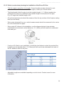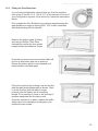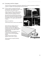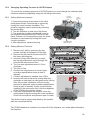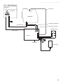
1
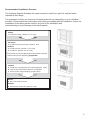
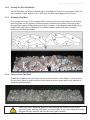
630292_0_ AUS NZ Installation Manual
ST900 Direct Vent Gas Fireplace
Installation Manual
NZ / AUS EDITION
Important:
The appliance shall be installed in accordance with;
• This installation instruction booklet
• Local gas fitting regulations
• Municipal building codes
• Electrical wiring regulations
• AS/NZS 5601, Gas installations
• Any other relevant statutory regulations.
• Must be installed by a qualified person
FOR SERIAL NUMBERS 43000 AND ABOVE.
Manufactured by: Escea Ltd, PO Box 5277 Dunedin New Zealand,
Ph: +64 3 478 8220, email: [email protected] www.escea.com
1
630292_0_ AUS NZ Installation Manual
Note:
THERE ARE A FEW THINGS TO CONSIDER BEFORE INSTALLATION
•
Cavity Dimensions and Clearances
•
MUST be installed a 100mm minimum off the floor or nearest horizontal surface.
•
Coupling of flue to fire
•
Coupling of gas lines to fire
•
Fixing the fire to cavity
•
Electrical mains socket at rear left corner of the cavity, to accommodate the power
transformer
•
Isolation switch for electrical transformer.
•
Gas pipe placement to the front left of the cavity.
•
The ST900 electronic control system is designed to work within the temperature range
of 0°C to 80°C without batteries and 0°C to 60°C with batteries, with a humidity level that is
non condensing. This is to ensure safe operation of the electronic and gas control system.
•
If the fireplace is subjected to an environment with temperatures very close to or exceeding
these temperature limits (irrespective of if the fireplace is on or off at the time) the fireplace
may not start up until the temperature returns back to within the operating range.
•
To remedy this, the environmental temperature should be addressed and the fireplace
control system given time to adjust accordingly. The fireplace should then function correctly.
•
It would be prudent to consider these operational limits during the installation planning
stage. Protecting the installed fireplace from low external ambient temperatures and cold
drafts through the use of approved modern building methods and materials will help ensure
that the required operating environment is maintained.
•
This fire is not intended as an insert (it must be flued in accordance with flue instructions
see section 12).
2
630292_0_ AUS NZ Installation Manual
WARNING:
Failure to follow these instructions could cause a malfunction of the fire, which,
could result in death, serious bodily injury, and/or property damage. Failure to follow
these instructions may also void insurance cover and/or product warranty.
Installation:
Installation must be carried out by a registered installer who, on completion of the
installation, must issue a certificate of compliance, in accordance with national and/or local
codes. If a certificate of compliance is not issued then the Escea warranty may be void.
Warranty Repair and Annual Servicing:
Warranty repair work must be carried out by a recognised Escea gas fire technician. It is
recommended that recognised Escea Gas fire technicians are also used to carry out annual
servicing requirements (particularly during the warranty period). For contact details of
authorised Escea technicians in your area, please contact the retailer from whom the
appliance was purchased.
This product must be installed according to these instructions and in compliance with all
relevant building, gas fitting, electrical and other statutory regulations (eg. AS/NZS 5601).
Any shortcomings in the appliance and flue installation will be the responsibility of the
installer, and Escea will not be accountable for any such failings or their consequences.
3
630292_0_ AUS NZ Installation Manual
PRODUCT SPECIFICATION
MODEL NAME
ST900
Description of Appliance
Star Rating
A/NZ Approval No.
Gas Type
Gas input (MJ/h)
Heat output (kW)
Decorative Gas Fire
N/A
AS 4558-2011 & NZS/AS4558-2013
Natural
ULPG
Propane
High
18 MJ/h
21 MJ/h
21 MJ/h
Low
12.9 MJ/h
15.40 MJ/h
15.40 MJ/h
High
3.0 kW
3.5 kW
3.5 kW
Low
High
2.10 kW
5.0kPa
1.2kPa
0.96 kPa
Low
0.52kPa
2.50 kW
5.0kPa
2.5kPa
2.30 kPa
1.30kPa
±0.1kPa
1.3mm
#23
Injector Size
Ø1.9mm
2.50 kW
5.0kPa
2.5kPa
2.30 kPa
1.30kPa
±0.1kPa
Ø1.25mm
Pilot injector
#37
#23
Maximum Inlet Pressure
Minimum Inlet Pressure
Operating Pressure
Appliance Dimensions (mm)
Weight
Width
Height
Depth
Kg
Ignition System
Ignition Activation
Flame Safeguard
Thermal Efficiency %
Electrical Supply
Consumption
Remote controls
Timers
Clock
Function lock / child
Temperature control
Connections
Data badge location
Electric
Gas
Flue
Type
Flue Size
Spigot
Location
902.4 mm
546.0 mm
352.2 mm
45 kg
Electronic Ignition to pilot system
(Maxitrol GV60)
10 secs (approx)
Thermocouple – magnetic cartridge
60% (EN 613:2000 6.11)
6.0V DC
2.3W @ 0.01A 230V
Yes
Yes
Yes
Yes
Yes
6.0V DC transformer and/or 4 x AA Cells
½ “ BSPT Male lower left of fireplace
Simpson Duravent (Balanced)
205 mm Outer, 125 mm Inner
Rear and centre at 60° to vertical
Lower left of fireplace
4
630292_0_ AUS NZ Installation Manual
Recommended Installation Process:
The following diagram illustrates the steps required to install your gas fire, and the trades
required at each stage.
The sequence in which you choose to do these tasks will vary depending on your individual
scenario. Please read these instructions fully before proceeding with the installation. Leave the
installation of the fascia panels until the very end of the installation and
commissioning to avoid damage to the fascia panels.
Builder
1. Construct Frame (Section 1.0 to 6.0)
Electrician
2. Install Electrical connection (Section 15.0)
Gasfitter
3. Install Gas Pipe (Section 7.0 to 8.0)
4. Install Fire (Section 9.0 to 12.0)
Ensure that you leave a gap between the studwork and fire
chassis to accept the wall lining if applicable.
Gasfitter
5. Install Flue + Flue Restrictor if required (Section 13.0)
6. Test fire and verify flame pattern is acceptable
7. Cover-up fire using packaging (Section 16.0)
Builder
8. Gib / line chimney breast
Gasfitter
9. Commission the Gas Fire (Section 17.0)
5
630292_0_ AUS NZ Installation Manual
Contents:
1.0
2.0
3.0
4.0
5.0
6.0
7.0
8.0
9.0
10.0
11.0
12.0
13.0
14.0
15.0
16.0
17.0
18.0
19.0
20.0
21.0
22.0
23.0
Product Description
Creating the Cavity
Hearth and Floor Clearances
Wall Linings
Vertical Clearances
Corner Installations
Laying Gas Pipe
Connecting Gas Pipe
Power Supply
Fixing Fire to Wall
Removing the Firebox Glass
Installing the Flue system
Fitting the Flue Restrictor
Converting to ULPG or Propane
Changing Operating Pressure to ULPG/Propane
Placing the Fuel Bed Media
Covering up the Fire
Commissioning the Fire (fitting the fascia)
Remote Instructions
Sounds and Smells
Annual Service Check
Installation Check List
Wiring Diagram
6
630292_0_ AUS NZ Installation Manual
1.0
Product Description:
The Escea ST900 decorative gas fire
is designed to be built into a cavity.
The appliance is flued via Simpson
Duravent Direct Vent Pro 5”x8” Flue,
available from your Escea distributor
or retailer. The user will control their
fire with the Radio Frequency (RF)
remote.
2.0
Creating the Cavity:
The cavity specifications vary depending on fascia type. The dimensioned drawings in the
following sections show the size of opening that must be created to fit the ST900. The wall
directly above the fire should be finished / gibbed / lined after the fire has been installed,
unless there is an access hatch or the chase is open to the ceiling cavity, which allows the
flue to be installed after the wall has been lined.
The wall and framework in front of the flue must not exceed 100mm in thickness, this
includes plaster board or any wall linings. This is to ensure there is at least 25mm gap
between all fluing components and any combustible material.
ONLY AVAILABLE
IN NEW ZEALAND
FERRO / MOLARIS FASCIA
Go to section 2.1
VELO FASCIA
Go to section 2.2
7
630292_0_ AUS NZ Installation Manual
2.1
Cavity for Ferro / Molaris Fascias
Note: It is not necessary to line the cavity,
and it may be constructed with timber.
Continue on to section 2.4
2.2
Cavity for Velo Fascias
ONLY AVAILABLE
IN NEW ZEALAND
Note: It is not necessary to line the cavity,
and it may be constructed with timber.
For Velo fascias, the fireplace should be recessed 12mm into the cavity.
Continue on to section 2.4
2.4
Considerations for creating the cavity:
If installing the ST900 into a purpose built chimney breast or
chase which is not open to the roof space of the building, it
may be appropriate during the planning stage to consider the
installation of additional vents.
Heat otherwise lost through the outer skin of the fireplace and
flue system into the cavity of the chimney breast or chase
may be recovered into the room by placing two air vents in
the cavity or chase. By placing one vent at or just above floor
level and the other near the ceiling of the room will induce
natural convection and prevent heat build up in the cavity and
subsequently recover some of the heat into the room.
3.0
Hearth and Floor Clearances:
There should be at least 100mm between the bottom of the ST900 fire and any horizontal
surface below, for example hearths and floors.
3.1
Wall and Cabinet Clearances:
There must be a minimum of 100mm from the sides of the fascia to any protruding side
walls or cabinetry.
8
630292_0_ AUS NZ Installation Manual
4.0
Wall Linings:
The wall board that lines the outside of this opening can be normal dry wall
(Plaster Board) and does not need to be non-combustible providing that it does not come
any closer to the fire than the dimensions shown in section 2.0. Note: The temperature of
the wall lining directly above the fire does get warm and hence may discolour paint
finishes that are susceptible to temperature damage or distort vinyl wall coverings.
5.0
Television Positioning Considerations:
It is becoming common practice for consumers to mount flat screen TV’s above their gas
fireplace.
Most TV manufacturers have specified in their instructions that the TV should not be
installed on, near or above a heat source. For this reason TV location decisions rest solely
with the householder and Escea will not be held liable for any adverse affects on a TV
located near to an Escea fireplace that may be caused by heat.
The drawings below are suggestions that may be used as a GUIDE for those consumers
who do decide to locate their TV above an ST900 gas fire. These drawings show ways to
reduce the amount of warm air rising off the fireplace and onto the TV.
Flush TV with
small mantle
Recessed TV
Mantle above fire
Protruding fire
50 min
50 min
50 min
100 min
50 min
50 min
50 min
50 min
100 min
Mantle
Mantle
500 min
500 min
500 min
500 min
The material that the wall and mantle are made from will also affect the operating
temperature of the TV so it is the customers responsibility to satisfy themselves that their
TV mounting and mantle design will not exceed the listed maximum operating temperature
of their electronic goods.
9
630292_0_ AUS NZ Installation Manual
5.1
Combustible Mantle Clearances:
The diagram to the right shows the minimum and
maximum allowable size for mantles or protruding
surfaces mounted above the ST900.
Note: Escea does not recommend placement of
items on the mantles shown in the diagram to the
right. This is because of the potential for items placed on
or above the mantle to be affected by the heat rising from
the appliance.
5.2
Non-Combustible Mantle Clearances:
If the entire installation (mantle, wall and cavity) is
constructed from non-combustible materials, the
clearances to mantles may be as shown in the shaded
area.
6.0
Corner Installations:
If a cavity is to be created in a corner,
the following table gives the minimum
sizes in millimetres.
Fascia Type
Ferro
Velo
7.0
A
380
392
B
910
940
C
835
862
D
1670
1724
Laying Gas Pipe:
Gas pipe should be sized as per the requirements of AS/NZS 5601. The pipe sizing must
be sufficient to deliver the following volume of gas to the fire with all other gas appliances in
the home running at the same time;
NG = 18Mj/hr
Propane/ULPG = 21Mj/hr
10
630292_0_ AUS NZ Installation Manual
8.0
Connecting the Gas Pipe:
Copper should be run directly to the fireplace and connected onto the Dormont hose with a
1/2” BSP thread nut.
Cavity
Cavity
S T900
S T900
Alternate gas
supply route
9.0
Power Supply:
Your fireplace has been supplied with a transformer and a battery back-up provision4 x AA Cells; located in top of the receiver (control) unit.
9.1
If you are using a power transformer:
Whilst the cavity is being created consideration should be given to appropriate location of a
standard 3 pin, 240V power outlet to accommodate the power transformer. This must be
within 1.5m of the lower left hand side of the appliance.
Locating this plug within the cavity makes the installation very neat but the provision must
be made to be able to switch the power supply off and on (electrical isolation switch) and
must be accessible after the fire has been installed. This is normally done by means of a
separate switch located outside of the cavity and wired to the plug. This will allow service
technicians to isolate the power supply before performing service work on the appliance.
The power transformer cord should be run, as shown below left, through the small
hole in the rear of the fire and connected to the panel mounted plug pictured below right.
Cavity
ST900
This appliance will draw a maximum of 2.5A (fused) from a 240V supply.
If a power transformer is plugged into the receiver, it will become the default power source.
The batteries (if fitted) will only be consumed if there is a mains power outage.
11
630292_0_ AUS NZ Installation Manual
10.0
Fixing the Fire to the base and wall:
It is a requirement that this fire be securely
fastened to the wall and base. Once the fire
has been pushed back into the correct
position, use wood screws (or other
suitable fasteners) to fix the fire to the
cavity through each of the four holes in the
corners, as shown in the diagram to the
right. Note: It may be necessary to use
washers on the fasteners to securely fasten
the fire to the wall.
When fixing the fireplace in position ensure
that you leave a gap between the fireplace
flange and the framing timber for the wall
lining, which will be added at a later stage.
11.0
Removing the Firebox Glass:
Pull the four hooks shown below towards you and then away from the glass to release the
glass frame underneath the hook.
Do not operate the appliance if the glass has been broken, damaged, or the glass is
not properly positioned/hooked onto the appliance.
12
630292_0_ AUS NZ Installation Manual
12.0
Installing the Flue System:
Ensure all flue components are Simpson Duravent Direct Vent Pro 5” x 8,” no other flue
types may be used.
Note: Consult section 12.13 to ensure correct length of flue is calculated.
There are two basic types of Balanced Flue System installations:
280.0
• Horizontal Termination
174.8
280.0
• Vertical Termination
Use the diagrams in sections 12.5, 12.6 & 12.7 to check if your proposed flue system is
acceptable. Section 12.9 will also need to be used to determine whether the flue terminal
location meets the requirements of AS/NZS 5601. Then use Appendix A to work out the
quantities of the flue components that are required.
12.1
Any offsets in your flue configuration should be 45° where possible.
12.2
If your flue configuration has a horizontal run, there must be a minimum 1 ° inclination
(20mm vertical rise per 1m horizontal run) leading upwards towards the termination.
Do not install the flue with horizontal sections sloping down towards the termination.
This could cause the fire to operate incorrectly and possibly create an unsafe
condition.
12.3
12.4
The flue must maintain the
following clearances to
combustible materials;
25mm from all sides and
bottom of the flue, and
50mm from the top of
the flue.
If your flue configuration falls
on or near a restriction zone
boundary line in diagrams
12.5, 12.6 & 12.7, it may
require the restriction value
from either side of the
boundary line to achieve the
correct flame aesthetic, this
may vary from installation to
installation.
Ø203mm
Ø265mm hole required in
wall to fit wall thimble
317mm
317mm
Optional Wall Thimble
200mm max120mm min
13
630292_0_ AUS NZ Installation Manual
12.5
Vertical Only Flue Diagram:
Use this diagram to
determine what
percentage of flue
restriction in required to
ensure safe and correct
operation of the ST900
decorative gas fireplace.
14
630292_0_ AUS NZ Installation Manual
12.6
Horizontally Terminating Flue Diagram:
Use this diagram to
determine what
percentage of flue
restriction in required to
ensure safe and correct
operation of the ST900
decorative gas fireplace.
15
630292_0_ AUS NZ Installation Manual
12.7
Vertically Terminating flue with a Horizontal Offset:
Use this diagram to
determine what
percentage of flue
restriction in required to
ensure safe and correct
operation of the ST900
decorative gas fireplace.
16
630292_0_ AUS NZ Installation Manual
12.8
Standard Flueing Configurations:
The following flue components are available from escea in kitset form.
DVF-H
DVF-V
17
630292_0_ AUS NZ Installation Manual
12.9
Locating the Flue Terminal:
The flue terminal must be located using the information given in the following diagram and
table based on AS/NZS 5601
18
630292_0_ AUS NZ Installation Manual
Table 16 – Minimum clearances required for flue terminals shown in figure 3
Ref.
Item
a
Below eaves, balconies and other projections:
Gas appliances up to 50 MJ/h input
Gas appliances over 50 MJ/h input
From the ground, above a balcony or other surface (see note 6)
From a return wall or external corner (see note 6)
From a gas meter (M) (see 2.5.4.9 for vent terminal location of
Regulator)
From an electricity meter or fuse box (P)
From a drain pipe or soil pipe
Horizontally from any building structure (see note 6) or obstruction
Facing a terminal
From any other flue terminal, cowl, or combustion air intake
(see note 6)
Horizontally from an openable window, door, non-mechanical air
Inlet, or any other opening into a building with the exception of
Sub-floor ventilation:
Gas appliances up to 150 MJ/h input
Gas appliances over 150 MJ/h input up to 200 MJ/h input
Gas appliances over 200 MJ/h input
All fan-assisted flue gas appliances, in the direction of
discharge
From a mechanical air inlet, including a spa blower
Vertically below an openable window, non-mechanical air inlet, or
Any other opening into a building with the exception of sub-floor
Ventilation:
Space heaters up to 50 MJ/h input
Other gas appliances up to 50 MJ/h input
Gas appliances over 50 MJ/h input and up to 150 MJ/h input
Gas appliances over 150 MJ/h input
b
c
d
e
f
g
h
j
k
n
Minimum Clearances (mm)
Natural
Fan
draught
assisted
300
500
300
500
200
300
300
300
1000
500
150
1000
500
75
500
500
500
300
500
1500
1500
300
300
500
1500
1500
1000
150
500
1000
1500
150
500
1000
1500
NOTE(1)
(2)
(3)
(4)
(5)
(6)
All distances are measured to the nearest part of the flue terminal
Prohibited area below electricity meter or fuse box extends to ground level
See 2.6.13.3 for restrictions on a flue terminal under a covered area
See appendix G LPG Cylinder Locations, figure G2 and figure G3, for clearances required from a flue terminal to
An LPG cylinder. A flue terminal is considered to be a source of ignition.
For gas appliances not addressed above, the design shall be certified by a suitably qualified engineer.
Some gas appliances may be suitable for closer installation; refer to the manufacturer’s instructions.
12.10 Supporting the flue system:
Wall straps are required to fix the flue system in place for each installation. This will ensure
that no undue strain is placed on flue components once installed.
For a flue offset or horizontal run, it is recommended that wall straps be used to the flue
system with a spacing of 900mm between straps. Plumbers strapping / tape can be used to
connect the wall straps to the building structure where there are large distances between
the support point and the anchor point.
For vertical flue runs it is recommended that wall straps be used to anchor the flue system
with a spacing of 1200mm between straps.
19
630292_0_ AUS NZ Installation Manual
12.11 Sealing ‘through roof’ and ‘through wall’ penetrations:
For ‘through roof’ penetrations, use a Deck-tite flashing or equivalent to create a weathertight seal between the flue and the roof cladding.
For ‘through wall’ penetrations, this will require the use of a Wall Thimble. The Wall Thimble
will ensure you have suitable clearance from combustibles as well as sealing the
penetration. The section of the wall thimble installed on the external surface of the wall
should be sealed to the wall using a high temperature sealant such as a High Temperature
RTV Silicone or equivalent. Additional sealant is required to seal the Terminal Cap to the
external wall. A bead should be run along the edge of the Terminal that will be in contact
with the wall once installed.
12.12 Twist locking procedure:
Before connecting flue components, to ensure an airtight seal run a single 7-8mm bead of
High Temperature RTV Silicone or equivalent, on the ‘male’ end of the flue as shown in the
diagram below.
The four indentations located on the female end of the flue are designed to slide straight
onto the male ends of the adjacent flue length, by orienting the four flue indentations so
they match and slide into the four entry slots on the male ends.
Push the pipe sections completely together, then twist-lock one section clockwise
approximately one-quarter turn, until the two sections are fully locked.
Wipe off any excess sealant from the exterior of the flue joint.
20
630292_0_ AUS NZ Installation Manual
12.13 Points to note when planning the Installation of the Escea DV flue:
-
This flue system cannot be cut to length. Correct lengths must be selected for each
installation. For a full list of available flue lengths, contact your Escea retailer.
-
The listed length of the flue pipe is not the installed length. 1 ½” (38mm) needs to be
subtracted for each join to determine the installed length of each piece of flue pipe.
E.g. 48” length has installed length of 45”.
-
All vertical measurements should be measured from the top surface of the fireplace casing
itself (not the fascia).
-
When using horizontal flue runs, vertical measurements should be measured to the centre
line of the horizontal flue pipes.
-
When using 90° elbows in the installation, use the diagram below to help calculate
installations horizontal and vertical distances. 1½” (38mm) will still need to be subtracted
from each join.
-
If using a 45° offset in your installation, consult the chart below to select the required flue
length to give the desired offset. 1½” (38mm) will still need to be subtracted from each of
the 45° bends to allow for the joins.
Straight
Flue Length:
0”
6”
9”
12”
24”
36”
48”
-
Offset:
Rise:
5 5/8”
8 7/8”
10 7/8”
13”
21 3/8”
29 7/8”
38 1/4”
15 3/8”
18 3/8”
20 5/8”
22 5/8”
31 1/8”
39 3/8”
47 7/8”
Adjustable lengths are available depending on stock levels. Contact escea for more
information.
21
630292_0_ AUS NZ Installation Manual
13.0
Fitting the Flue Restrictor:
If your flueing configuration requires that you fit a flue restrictor
(see graph in section 12.5, 12.6 & 12.7 of this manual to find out if
your configuration requires a flue restrictor), follow the instructions
below.
First, prepare the Flue Restrictor by removing and discarding the
appropriate inner rings to achieve 60%, 70% or 80% restriction
and hand bending the five tabs 90°.
Remove the firebox glass (if fitted),
and using a Phillips / Pozi Drive
screwdriver remove the two screws
located inside the firebox as shown.
Once the two screws are removed the baffle will
be free to slide down and out as pictured.
Ensure the firebox paint is not scratched and
that the baffle is not damaged.
Fit the flue restrictor by pushing it up into the flue
with the tabs facing downwards as shown. Push
it up into the flue until the tabs no longer
protrude into the firebox and it is securely
placed. If the restrictor is loose or will not stay in
position manipulate the five tabs to suit.
Once the restrictor is in place, replace the baffle
taking care not to damage or scrap paint, and
replace the two screws.
22
630292_0_ AUS NZ Installation Manual
14.0
Converting to ULPG or Propane:
This fire has been supplied & configured for Natural Gas; where a conversion to ULPG or
Propane is needed, the following steps should be followed.
14.1
First you need to remove the burner by
removing the screw holding it in place on the
left hand side of the firebox (Fig. 1).
Then remove the burner jet (Fig. 2) and
replace it with the 1.3mm jet (Propane) or
1.25mm jet (ULPG) supplied in the kit.
Now remove the gas pipe fitting under the
pilot (Fig. 3) and remove the pilot Jet (Fig. 4)
and replace it with the No.23 pilot jet supplied
in the kit. No. 23 is used for both ULPG &
Propane.
Replace the pilot line.
Check the pilot line for leaks once assembled.
Set the Primary Aeration Collar on
the burner to the ULPG/Propane
position as shown in the diagram by
removing the screw in the side and then
replacing it when the collar is in the
correct position.
NOTE: the collar is only able to be set
to either NG or Propane/ULPG
positions. This is not an adjustable
system.
Place the burner back into the
appliance and screw it in place.
Set the pressure using the following
instructions:
23
630292_0_ AUS NZ Installation Manual
15.0
Changing Operating Pressure to ULPG/Propane
To convert the operating pressure to ULPG/Propane you must change the maximum and
minimum pressures separately using the following instructions:
15.1
Setting Maximum pressure:
1. Connect a pressure manometer to the valve
outlet pressure tap. Pressure tap is opened by
turning the screw counter-clockwise. The
pressure regulator can be reached by removing
the domed-plug.
2. Turn the fireplace on and set to high flame.
3. Turn pressure regulator adjustment screw to
set required burner pressure of 2.3kPa on high
flame. Pressure is increased by turning the screw
clockwise or decreased by turning the screw
counter-clockwise.
4. After adjustment, replace the plug.
15.2
Low Rate
Adjustment
Screw
Outlet
Pressure
Tap
Pressure Regulator
Adjustment Screw
Setting Minimum Pressure:
1. Remove front infill by removing the two
screws circled in the diagram to the right.
2. Remove the M6 machine screw circled in
the lower right diagram.
3. Use 4mm long-reach Allen key to reach
the low rate adjustment screw through the
hole the M6 was removed from.
4. Turn low rate adjustment screw 1/3 turn
clockwise.
5. Turn fire on low.
6. Confirm low rate pressure is correct (refer
to product specification sheet at start of
manual).
7. If further adjustment is needed, turn off fire.
8. Increase low rate pressure by turning Allen key
clockwise or decrease low rate pressure by turning
Allen key counter-clockwise, until the correct
pressure is achieved (refer to product specification
sheet at start of manual). Finally, put the sticker
supplied in the conversion kit in onto the dataplate
of the ST900 in the position shown.
9. If no other adjustments are required, close the
outlet pressure tap by turning the screw clockwise.
Check all connections and pressure taps for leaks.
The sticker must be signed and dated by the installer
who has converted the fire.
The ST900 dataplate is located in the lower left of the fireplace, on a metal plate tethered to
the fireplace.
24
630292_0_ AUS NZ Installation Manual
16.0
Placing the Fuel Bed Media:
Your ST900 Gas fire will be supplied with a Fuel Bed kit. Follow the instructions below for
the Fuel Bed kit that applies to you. USE only fuel bed media approved by Escea.
16.1
Driftwood Fuel Bed:
First scatter one layer of the supplied white stones evenly across the base of the firebox,
ensuring there are no stones or driftwood pieces inside the pilot flame surround guard.
Arrange the supplied driftwood pieces exactly as shown in the diagram and photo below.
Underneath each piece of driftwood is a written number which will help in correctly
positioning it within the firebox.
16.2
Coal or Glass Fuel Bed:
Scatter the supplied fuel bed media evenly across the base of the firebox, ensuring there
are no coals, glass or media inside the pilot flame surround guard which may obstruct or
impair the pilot assembly.
Ensure no coals, driftwood, glass, or other material are inside the pilot flame
surround guard, and the pilot flame is clearly visible. If any loose material is inside
this guard it may interfere with the pilot and ignition system.
25
630292_0_ AUS NZ Installation Manual
17.0
Covering up the fire:
Before the wall surrounding the ST900 is lined, the fire must be covered up and sealed to
prevent Gib dust from getting into the fire. It is recommended that the packaging supplied
with the fire is used to achieve this.
18.0
Commissioning the Fire:
After the cladding and finishing processes are completed, the gasfitter must return to the
site to run the fire for a minimum of 20 minutes and finally assemble and fit the fascia and
associated accessories.
→ If you are installing a FERRO fascia:
SEE SECTION 18.1
→ If you are installing a VELO fascia: (Available in NZ only)SEE SECTION 18.2
18.1
Assembling the Ferro fascia:
1.
The ST900 Ferro fascia has two brackets supplied in the fascia box which have not been
fully assembled. To assemble them use the 4x screws supplied to fasten the brackets to the
fascia as shown below. Position the brackets with the flange facing outwards, and the
hooks facing the bottom of the fascia [Identify the bottom of the fascia by the large cut-out
shown below].
26
630292_0_ AUS NZ Installation Manual
2.
Fitting the Grill Trim:
Packed in with the fascia kit is the Grill
Trim. Attach this to the fire using the 3
supplied screws in the positions shown to
the right. The perforated surface (grill)
should be on top.
3.
The ST900 fascia uses these four hooks
for attaching to the fire. Do this by lining up
the fascia hooks with the receptacles on
the sides of the fire. Lift the fascia so that
the hooks are above the receptacles, and
let it drop down into
position until it is secure and free from movement.
Remove all protective plastic and packaging
material before operating the fire. Care should
be taken when handling the fascia.
To remove the Fascia, lift it upwards briefly, and then
pull towards you. Ensure the fascia is allowed to cool
before attempting to remove it.
→ Continue on to section 19.0
27
630292_0_ AUS NZ Installation Manual
18.2
Assembling the Velo fascia:
Preparation:
1.
The supplied upper baffle must be removed
and discarded before continuing with the
install. To do so, undo the 4x screws shown
right and remove the baffle by lifting it
upwards and outwards as shown.
2.
3.
4.
Install the Heat Deflector to the top of the fireplace using the 3x supplied screws with
the Heat Deflector facing outwards as shown.
Install the supplied Upper Baffle (the part with grill fitted) into the fireplace with grills
facing downwards. Fix in place using the 4x supplied screws in the position shown.
Install the lower fascia magnet brackets using the 4x supplied screws in the two
positions shown below. (Do not affix the magnets at this stage)
2
3x
3
2x
4
2x
Installation:
5.
The ST900 fascia uses the hooks on the rear
for attaching to the fire. Line up the hooks
with the receptacles on the sides of the
fireplace, and lift the fascia so that the hooks
are above the receptacles. Let it drop down
into position until it is secure and free from
movement. The Heat Deflector (2) should sit slightly inside the fascia so that the
fascia can sit tight against the wall.
6.
Attach the supplied Magnets to brackets installed in step 4 above, using the supplied
nuts and bolts
7.
Place lower trim by securing it to the magnet brackets attached in step 3.
28
630292_0_ AUS NZ Installation Manual
18.4
Cleaning the ST900 Fascia:
The fascia must be cold before starting any form of maintenance or cleaning.
If your Stainless Steel fascia requires cleaning, 3M Stainless Steel cleaner (or equivalent) is
recommended.
If your Powder Coated (Painted) fascia requires cleaning, you must only use a damp nonabrasive cloth to give it a gentle wipe. Never ever rub the fascia.
18.5
To clean the glass, remove it as described in section 11.0 and clean inside and out using
standard window cleaner. Do not allow glass to become excessively dirty as this will be
difficult to remove.
DO NOT ATTEMPT TO CLEAN THE GLASS WHILE IT IS HOT. NEVER OPERATE THE UNIT
WITH THE GLASS REMOVED.
29
630292_0_ AUS NZ Installation Manual
19.0
Remote Instructions
19.1
Pairing the Remote to the Control Unit:
The remote supplied is already paired with the receiver (control) unit in the factory. Use the
following only when required:
1. Press and hold the receiver’s reset button (refer to section 23.0 for location) until you
hear two beeps. The first beep is short and the second beep is long. After the second
beep release the reset button.
2. Within the subsequent 20 seconds, press the down button on the handset until you hear
two additional short beeps confirming the code is set. If you hear one long beep, this
indicates the pairing has failed or the wiring is incorrect.
NOTE: Pairing is not required after changing the batteries of the remote or receiver.
19.2
Remote Operational Instructions (REFER TO USER MANUAL)
20.0
Sounds And Smells:
Note: Each time the fire is lit from cold the glass will fog up with condensation. This is
normal and the condensation will disappear within a few minutes once the glass heats up.
20.1
Sounds:
It is possible that you will hear some sounds from your gas appliance. This is perfectly
normal due to the fact that there are various types of materials used within your appliance.
Listed below are some examples. These are all normal operating sounds and should not
be considered as defects in your appliance. When the fire is switched off after being run for
a while, there may be popping and fluttering noises as the residual gas in the burner burns
away. These are normal and should be no cause for concern.
Unit Body/Firebox:
Different types and thickness’ of steel will expand and contract at different rates resulting in
some “dull drumming” and “ticking” sounds being heard throughout the cycling process.
20.2
Smells:
The first few times the unit is operated, the unit may release an odour and the flames may
appear orange caused by the curing of the paint, the burning off of the starch in the gas
coals and the oils in the metal and finishes. This is a temporary curing process which will
disappear with use.
A deposit on the inside of the glass, caused by the starch in the coals may appear as a
build up after several uses. If this film is not removed, it may bake on and may become
difficult to remove. When the glass is cold, remove it (see section 11.0) and clean the inside
with a non-abrasive cleaner.
DO NOT ATTEMPT TO CLEAN THE GLASS WHILE IT IS HOT. NEVER OPERATE THE UNIT
WITH THE GLASS REMOVED.
30
630292_0_ AUS NZ Installation Manual
21.0
Annual Service Check
The ST900 Fireplace should be serviced annually to ensure it continues to operate in a safe
manner. This annual service check should involve the following
x Check thermocouple holds the cartridge
x Check glass assembly gasket
x Clean pilot and main burner jets
x Paint firebox [if required]
x Inspect flue system [if possible]
x General clean and inspection
22.0
Installation Check List:
1
Fuel Bed Media correctly installed as per manual
2
Operating pressure checked with fire running on full (high flame setting)
and all other gas appliances in the house switched on.
3
Flue restrictor fitted if required, flame picture verified 15 minutes
after start-up.
4
Ensure the pilot frame is clearly visible and free from loose
material (coals).
5
After plasterboard installation, fire run on high for 60 minutes with house doors
and windows open to clear smell of paint and oils initial burn.
6
Fire and flue clearances comply with these instructions.
7
Fire securely fixed to wall.
8
Leak test all joints and pressure test points. Soapy water and drop test
done on pipe work.
9
Remote cradle screwed to wall.
10
House holder has been shown how to operate fire.
11
User manual has been left out for house holder, installer has filled in their
own details and fire serial number into warranty card.
12
Inform the customer that the fire may continue smelling for a while after
installation depending on frequency & duration of use
13
Given house holder Plumbing Industry Commission Compliance
Certificate.
31
630292_0_ AUS NZ Installation Manual
23.0
Wiring Diagram:
Main Burner
8 Wire Cable
Pilot Burner
GV60 Valve
Thermocurrent Cable SW
Interrupter Block
Thermocurrent Cable TC
Membrane Switch
Ignition Cable
Receiver
Reset Button
+9V
Power Supply
32
630292_0_Manual Service ST900 NZ R-emotion
630292_0_Manual Service ST900 NZ R-emotion
630292_0_Manual Service ST900 NZ R-emotion
15.0 Troubleshooting
Use the following troubleshooting chart to diagnose and fault-find operational issues
with the ST900 gas fireplaces.
Problem
Cause
Remote may not be paired
Batteries are dead or no batteries fitted (ONLY if
batteries are the sole source of power).
Transformer is turned off or mains power failure.
8-pin connector has bent pins
No response from the valve Motor wiring is damaged
Damaged Remote
Damaged Receiver
The dial on the valve is set to MAN
Spark is not present in
ignition sequence
One long 5 second beep
(might be 7 short beeps
before the long 5 second
beep)
Ignition wire is in contact with a metal part on the
appliance
Ignition rod is worn out or damaged
Wiring is loose
Damaged Receiver
8-pin connector has bent pins
Valve is damaged
Air in the gas pipes
No pilot Flame (sparking but
Thermocouple wires are transposed
no gas)
Pilot Injector is blocked
Ignitor is continually
Damaged Receiver
sparking while the burner is
lit
Thermocouple is not functioning correctly
Pilot is burning correctly but
the control valve closes
after approximately 10
seconds or when the
appliance gets too hot
Batteries are close to empty
Multiple Short beeps but no Batteries are close to empty
response can be heard from
the control valve and no
spark is present.
The dial on the valve is set to MAN
Solution
Follow instructions from section 19.1 of the
Installation Manual
Replace the batteries using the instuctions
from page 5 of the User Guide
Turn on transformer or rectify loss of mains power.
Straighten the pins on the 8-pin connector
Repair the motor wiring
Replace the Remote and pair the remote
using instructions from section 9.1 of the
Installation Manual
Replace the receiver and pair the remote
using instructions from section 9.1 of the
Installation Manual
Switch dial on the valve to ON
Prevent the ignition wire from touching any metal
parts on the appliance
Replace the ignition rod
Connect the wiring correctly as shown in the wiring
diagram in section 23.0 of the Installation Manual
Replace the reciever and pair the remote to the new
receiver using instructions from section 19.1 of the
Installation Manual
Straighten the pins on the 8-pin connector
Replace the control valve
Purge the line using the outlet pressure tap or wait it
out by attempting the ignition sequence several
times
Connect the thermocouple wires correctly as per the
diagram in section 23.0 of the Installation Manual
Carefully clean the injector
Replace the reciever and pair the remote
using instructions from section 9.1 of the
Installation Manual
Use a multimeter to measure mV from the wires to
the interruptor block. The voltage should read at least
5mV within a 20 second time period. Must not be
lower than 5mV when the appliance is hot. If the
voltage was under 5mV, the thermocouple should be
replaced.
Replace the batteries using the instuctions
from page 5 of the User Guide
Replace the batteries using the instuctions
from page 5 of the User Guide
Switch dial on the valve to ON
Pilot is lit but there is no gas
flow to the main burner
Valve is damaged
Replace the control valve
630292_0_Manual Service ST900 NZ R-emotion
13.0 Re-establish Power and Gas Connections
With all applicable service work completed and the fire fully assembled again the gas
can be re-established and the batteries replaced.
Check gas inlet pressure against data plate at the inlet pressure tap using a
manometer. Adjust gas pressure to specifications stated in the product specification
page in the front of the Installation Manual.
Remove the manometer and tighten the test point screw.
Leak test all test points and gas system joins/unions.
Check that the pilot flame correctly impinges on the flame failure device
(thermocouples should not glow red, as this indicates that the pilot flame is set too
high and will reduce the life of the thermocouple).
14.0 Re-fit the Fascia
The fascia uses these four hooks for attaching to the fire. Do this by lining up the
fascia hooks with the receptacles on the sides of the fire. Lift the fascia so that the
hooks are above the receptacles, and let it drop down into position until it is secure
and free from movement.
630292_0_Manual Service ST900 NZ R-emotion
10.0 Inspect Flue System [if possible]:
If you have access to the flue system, inspect it for damage or potential blockages
(including the cowl). Ensure each flue component is twist-locked into the adjacent
components, and that there are no combustible objects or material within 25mm of
either side or below flue components or 50mm above any flue components, as
shown in the diagram below:
50mm
50mm
25mm
25mm
25mm
Flue
25mm
25mm
25mm
11.0 General Clean and Inspection:
A general clean of the fire should be undertaken by wiping down or dusting all
accessible areas and surfaces.
12.0 Re-assemble
Once the service work is complete, the fire should be re-assembled by reversing the
actions done in previous steps, replacing the pilot cover, burner, fuel bed media,
glass assembly, and control tray (if removed).
6.0
7.0
630292_0_Manual Service ST900 NZ R-emotion
Other components on the control tray can be replaced when necessary while tray is
separate from the fireplace.
When replacing the tray, make sure to reconnect all gas pipes tightly and using
sealant where required. A leak test should be done on all disturbed fittings using a
soapy water solution.
NOTE: When re-tightening the electrode nut, be sure not to over-tighten as this will
damage the electrode’s ceramic insulator.
Check Glass Assembly:
Check that the glass assembly (Removed in section 3.0) for
damage to glass or sealing tape. If the glass has any visible
damage it must be replaced before use.
Ensure the tape which seals the glass against the firebox is in the
correct position (shown to the right) and that the glass is secure
inside the metal frame and free from movement.
Clean Pilot and Main Burner Jets:
With the burner removed the burner jet is now accessible. Remove the jet and clean
it using an appropriate method, such as using a micro drill or compressed air.
8.0
Clean Thermocouple:
With the pilot cover removed you now have access to clean the thermocouple. Do
this by wiping it down with a rag or other appropriate cleaning tools in order to
remove any soot from the surface.
9.0
Paint Firebox [if required]:
If there are any scrapes or damage to the paint on the inside of the firebox you may
wish to touch up the paint. To do this, use a suitable high temperature matt black
paint. Do not put any paint on the burner, as there is a risk of blocking burner ports.
5.0
630292_0_Manual Service ST900 NZ R-emotion
Remove Control Tray [if required]:
If the thermocouple needs to be replaced, or the control tray needs to be cleaned
and/or repaired, it may be necessary to remove the control tray from the appliance.
(B,D,E)
(A)
(C)
(F)
(G)
1. First disconnect the main gas connection (A) at the appliance connection, the nut
(B) connecting the pilot tube to the pilot assembly, and the nut (C) connecting the
main burner pipe to the valve.
2. Remove the burner and the brass nut that retains the burner nozzle from the
inside R/H face of the firebox. The main burner gas pipe may now be removed.
3. Then detach the electrode by pulling downwards on the grey wire attached to the
pilot assembly and unscrew the electrode nut (D) and remove the electrode.
4. The thermocouple nut (E) attached to the pilot assembly (rear nut) should now be
unscrewed, followed by carefully pulling the thermocouple downward to
disengage from the pilot assembly.
5. Disconnect the touch pad (membrane switch) and the transformer from the
receiver.
6. Once the two screws (F+G) pictured above are removed the tray is free to be lifted
(ensuring that all wiring is clear from sheet metal) up 15mm to clear the metal
edge and pulled towards you.
If the thermocouple needs to be replaced, unscrew from the interrupter block. It can
then be replaced with the replacement thermocouple and tightened into the
interrupter block.
Note: A stainless steel sleeve (highlighted red in lower left picture) must be present
and situated as shown before installing the thermocouple. When installing the
thermocouple, push the thermocouple upwards as far as possible during the
tightening of the nut to achieve the correct height for the thermocouple to sit. Check
that it is at the correct height by referring to the bottom right picture.
3.5mm/
0.13"
4.0
630292_0_Manual Service ST900 NZ R-emotion
Remove Firebox Contents:
Ensure the firebox contents have cooled down completely
before attempting to touch or remove any part.
First remove all fuel bed media (driftwood, white stones
or coals) and place them carefully to the side somewhere
they will not be damaged.
The driftwood logs are very fragile – Use extreme care!
Next remove the burner by removing the screw holding
it in place as shown to the right, and then lifting the left side
of the burner upwards and sliding the burner off the jet on
the right hand side.
You will also need to remove the pilot cover (The long grill at the front of the firebox)
in order to access and clean the pilot and thermocouple. To do this, remove the two
screws on either side of the pilot cover and lift upwards, as shown below, taking care
not to scrape or damage the firebox as shown below.
1.0
630292_0_Manual Service ST900 NZ R-emotion
Isolate Power and Gas Supply:
Before any service and maintenance work is done on the fire, the gas supply must be
isolated or shut off. Gas can be isolated by either turning the gas off at the cylinders,
at the meter or at the appliance isolation valve. Power can be isolated by removing
the batteries from the battery pack and/or powering off the transformer.
2.0
Remove the Fascia:
Ensure the fascia has cooled before attempting to remove it.
The fascia attaches to the fire by four hooks. To remove the fascia, simply lift it
upwards 15-20mm, and pull towards you. Care should always be taken when
handling the fascia.
3.0
Remove Glass Assembly:
Ensure the glass assembly has cooled completely before attempting to remove it.
Pull the four hooks shown below towards you and then away from the glass to
release the glass frame underneath the hook. Lift the glass assembly towards you to
clear the locating supports and place it flat upon some newspaper or a sheet of
cardboard to protect your floor coverings
630292_0_Manual Service ST900 NZ R-emotion
Contents:
DIS-ASSEMBLY
SERVICE
RE-ASSEMBLY
-
Isolate power and gas supply
Check glass assembly
-
Remove Control Tray [if required]
-
Remove firebox contents
-
Remove glass assembly
-
Remove fascia
-
-
-
Re-assemble
-
General clean and inspection
-
Inspect flue system [if possible]
-
Paint firebox [if required]
-
Clean burner thermocouple
-
Clean pilot and main burner jet
-
-
-
-
Replace fascia
-
-
Re-establish gas and electrical
connections
-
TROUBLESHOOTING
-
1.0
2.0
3.0
4.0
5.0
6.0
7.0
8.0
9.0
10.0
11.0
12.0
13.0
14.0
15.0
630292_0_Manual Service ST900 NZ R-emotion
ST900 Direct Vent Gas Fireplace
Service Guide
AUSTRALASIAN EDITION
Important
x
x
x
It is recommended that this appliance be serviced every 12 months
Any service operation should be carried out only by a suitably qualified and trained person
Gas and electricity supply MUST be isolated before any service operation is carried out on this
appliance.
Manufactured by: Escea Ltd, PO Box 5277 Dunedin New Zealand, Ph: +64 3 478 8220, email: [email protected]
For contact details of your local escea distributor or dealer please visit www.escea.com