1
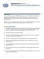
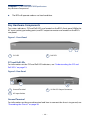
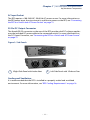
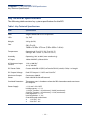
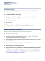
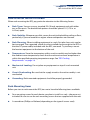
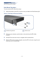
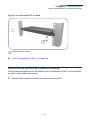
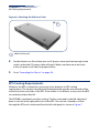
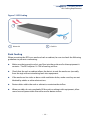
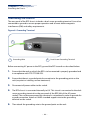
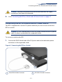
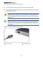
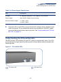
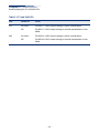
RPS900W
Redundant Power Supply
I n s t a l l a t i o n G u id e
www.edge-core.com
I n s t a ll a ti o n G u id e
RPS900W Redundant Power Supply
Single DC Output Port with Dual Output Voltages
RPS900W
E102013-CS-R01
150200000812A
How to Use This Guide
This guide includes detailed information on the RPS hardware, including power
requirements and LED status indicators . This guide also provides general installation
guidelines and recommended procedures. To deploy this RPS effectively and ensure
trouble-free operation, it is recommended to first read the relevant sections in this
guide so that you are familiar with all its hardware components.
Who Should Read This Guide?
This guide is for network administrators and support personnel that install, operate,
and maintain network equipment. The guide assumes a basic working knowledge of
network equipment and can be read by either those that are new to network
equipment, or those with more experience.
How This Guide is Organized
The organization of this guide is based on the RPS’s main hardware components. Each
chapter includes information about a specific component with relevant specifications
and installation procedures.
The guide includes these chapters:
◆
Chapter 1 - RPS Description and Specifications—Includes an RPS overview, key
component identification and key technical specifications.
◆
Chapter 2 - Installing the RPS—Includes RPS chassis rack installaion, system
cooling requirements, RPS grounding, connecting the RPS to a switch, AC power
requirements, and status LEDs.
◆
Appendix A - Troubleshooting—Information for troubleshooting RPS installation
and operation.
– 5 –
How to Use This Guide
Conventions
The following conventions are used throughout this guide to show information:
Note: Emphasizes important information or calls your attention to related
features or instructions.
Caution: Alerts you to a potential hazard that could cause loss of data, or
damage the system or equipment.
Warning: Alerts you to a potential hazard that could cause personal injury.
Revision History
This section summarizes the changes in each revision of this guide.
October 2013 Revision
This is the first revision of this guide.
– 6 –
Contents
1
2
A
How to Use This Guide
5
Contents
7
RPS Description and Specifications
9
Overview
9
Key Hardware Components
10
Key Technical Specifications
12
Installing the RPS
13
Package Contents
14
General Installation Guidelines
14
How to Install the RPS in a Rack
15
How to Install the RPS on a Shelf or Desktop
17
RPS Cooling Requirements
18
Grounding the Chassis
20
Connecting the RPS to a Switch and AC Power Source
21
Understanding the SYS and PoE LEDs
23
Troubleshooting
25
Diagnosing LED Indicators
25
Power and Cooling Problems
25
Installation
25
– 7 –
Contents
– 8 –
1
RPS Description and Specifications
Overview
Thank you for choosing the RPS900W redundant power supply (RPS). This RPS is built
to provide a reliable redundant power source for Edge-Core ECS4510-52P and
ECS4620-52P PoE-enabled switches that are equipped with a redundant DC power
input connector.
In the event of an AC power outage or failure of the switch’s internal power supply, this
RPS can supply up to 900 Watts of backup power for your PoE switch.
Features and Benefits
◆
Designed to support the Edge-Core ECS4510-52P and ECS4620-52P switches with
an 11.3 VDC supply of up to 126 W and a 54 VDC supply of up to 780 W. (The AC
power is managed by software with an upper limit of 730 W for PoE.)
◆
Indicator LEDs located on the front panel.
◆
The RPS AC cord can draw power from a seperate AC power source, for example,
an Uninterruptible Power Supply (UPS).
◆
Custom DC power cable provides backup power to the switch from the RPS.
◆
Thermal overload protection prevents the RPS from overheating if a thermal
overload occurs.
◆
Over-voltage protection shuts down the output channel if the voltage exceeds a
preset threshold.
◆
Over-current protection shuts down the RPS if the output load exceeds a preset
threshold.
◆
Short-circuit protection prevents the RPS from being damaged from a short circuit
on either output channel.
– 9 –
Chapter 1
| RPS Description and Specifications
Key Hardware Components
◆
The RPS will operate under a no-load condition.
Key Hardware Components
Two status indicators, SYS and PoE LEDs, are located on the RPU’s front panel. While the
AC input socket, grounding point, and DC output connector are located on the RPU’s
rear panel.
Figure 1: Front Panel
1
1
2
SYS LED
2
PoE LED
SYS and PoE LEDs
For information on the SYS and PoE LED indicators, see “Understanding the SYS and
PoE LEDs” on page 23.
Figure 2: Rear Panel
1
2
1
Ground Terminal
2
AC Input Socket
3
3
25-Pin DC Output Connector
Ground Terminal
For information on the ground terminal and how to connect the chassis to ground, see
“Grounding the Chassis” on page 20.
– 10 –
Chapter 1
| RPS Description and Specifications
Key Hardware Components
AC Input Socket
The RPS requires a 100-240 VAC, 50-60 Hz AC power source. For more information on
the RPS power input, how to connect it, and how to power-on the RPS, see “Connecting
the RPS to a Switch and AC Power Source” on page 21.
25-Pin DC Output Connector
The female DB-25 connector on the rear of the RPS provides dual DC voltage supplies
over the included DC power cable to the connected switch. For more information on
the DC Ouput Connector, see “Connecting the RPS to a Switch and AC Power Source”
on page 21
Figure 3: Side Panels
1
2
1
SRight Side Panel with Intake Vent
2
Left Side Panel with 3 Exhaust Fans
Cooling and Ventilation
It is recommended that the RPS is installed in a properly cooled and ventilated
environment. For more information, see “RPS Cooling Requirements” on page 18.
– 11 –
Chapter 1
| RPS Description and Specifications
Key Technical Specifications
Key Technical Specifications
The following table contains key system specifications for the RPS.
Table 1: Key Technical Specifications
Item
Specification
Ports
Single Female DB-25 DC Output Port
LEDs
Sys, PoE
Weight
3.9 kg (8.6 lb)
Size
(W x D x H):
18.00 x 16.50 x 3.75 cm (7.09 x 6.50 x 1.48 in)
Temperature
Operating: 0° C to 55° C (32° F to 122° F)
Storage: -40° C to 85° C (-40° F to 158° F)
Humidity
Operating: 10% to 90% (non-condensing)
AC Input
100 to 240 VAC @ 50 to 60 Hz
AC Maximum Input
Current
12 A @ 100 VAC
6 A @ 240 VAC
DC Power Cable
Custom Male DB-25 (RPS) to Female DB-25 (switch) Cable, 1 m length
DC Output Voltage
Dual DC Output 11.3 VDC and 53.8 VDC
Maximum Output
Power
Continuous: 900 W.
Peak:1010 W for 50 milliseconds
Overload Protection
The output port is shutdown when the RPS demand exceeds maximum
RPS outputs.
Power Supply
+11.3 and + 53.8 VDC
Initial accuracy: +/- 1%
11.3 VDC Current: 1 A (minimum), 10.0 A (maximum)
53.8 VDC Current: 1 A (minimum), 14.3 A (maximum)
Line regulation: +/- 1%
Load regulation: +/- 4%
Overshoot and undershoot:
◆
11.3 VDC - 5%
◆
53.8 VDC - 6%
– 12 –
2
Installing the RPS
The RPS is designed to be installed in a standard 19-inch equipment rack.
Before continuing with the RPS installation, first review the general guidelines and RPS
cooling requirements in this chapter.
This chapter includes these sections:
◆
“Package Contents” on page 14
◆
“General Installation Guidelines” on page 14
◆
“How to Install the RPS in a Rack” on page 15
◆
“How to Install the RPS on a Shelf or Desktop” on page 17
◆
“RPS Cooling Requirements” on page 18
◆
“Grounding the Chassis” on page 20
◆
“Connecting the RPS to a Switch and AC Power Source” on page 21
◆
“Understanding the SYS and PoE LEDs” on page 23
– 13 –
Chapter 2
| Installing the RPS
Package Contents
Package Contents
After unpacking the RPS, check the contents to be sure you have received all the
components.
◆
RPS900W Redundant Power Supply
◆
Rack Mounting Kit — Contains two mounting brackets and eight screws for
attaching the brackets to the RPS.
◆
Four adhesive foot pads
◆
AC power cord
◆
DC power cable — 1 m (3.28 ft) male-to-female DB-25 connectors
General Installation Guidelines
Be sure to follow the guidelines below when choosing a location.
The installation location should:
◆
be able to maintain its temperature within 0 to 55 ° C (32 to 122 ° F) and its
humidity within 10% to 90%, non-condensing.
◆
provide adequate space (approximately five centimeters or two inches) on all sides
for proper airflow.
◆
be accessible for installing, cabling and maintaining the device.
◆
allow the status LEDs to be clearly visible.
◆
Make sure that the unit is connected to a separate grounded power outlet (ideally
a UPS power source) and is powered from an independent circuit breaker. As with
any equipment, using a filter or surge suppressor is recommended. Verify that the
external AC power requirements for the RPS can be met as listed under Table 2,
“AC Power Supply Specifications,” on page 23.
– 14 –
Chapter 2
| Installing the RPS
How to Install the RPS in a Rack
How to Install the RPS in a Rack
When rack mounting the RPS, pay particular attention to the following factors:
◆
Rack Types: You can use any standard EIA 19-inch equipment rack with either
two or four posts. The bracket hole pattern should be spaced 1U (1.75 in. or
4.45 cm) apart.
◆
Rack Stability: Whenever possible, secure the rack to the building ceiling or floor,
particularly if you are located in a region where earthquakes are common.
◆
Rack Planning: When installing equipment in a rack, first plan how units can be
best arranged. The supported switch must be installed close enough to the RPS so
that the DC power cable, included with the RPS, can reach. Try to always mount
the heaviest equipment at the bottom of the rack.
◆
Temperature: Since the temperature within a rack assembly may be higher than
the ambient room temperature, check that the rack-environment temperature is
within the specified operating temperature range. See “RPS Cooling
Requirements” on page 18.
◆
Mechanical Loading: Do not place any equipment on top of a rack-mounted
unit.
◆
Circuit Overloading: Be sure that the supply circuit to the rack assembly is not
overloaded.
◆
Grounding: Rack-mounted equipment should be properly grounded.
Rack-Mounting Items
Before you start to rack-mount the RPS, be sure to have the following items available:
◆
Four mounting screws for each device you plan to install in a rack—these are not
included. Be sure to use the rack mounting screws that are supplied with the rack.
◆
A screwdriver (Phillips or flathead, depending on the type of screws used).
– 15 –
Chapter 2
| Installing the RPS
How to Install the RPS in a Rack
Rack-Mount Procedure
To rack mount the RPS, follow these steps:
1. Attach the brackets to the RPS using the screws provided in the Rack Mounting Kit.
Figure 4: Attaching the Extension Brackets
2
1
1
Rack Mounting Bracket
2
Bracket Screws
2. Following your rack plan, mark the holes in the rack where the RPS will be
installed.
3. Lift the RPS into the rack so that it is aligned with the marked holes.
4. With the RPS brackets properly aligned, secure the RPS in the rack, using four rackmounting screws (not provided).
– 16 –
Chapter 2 | Installing the RPS
How to Install the RPS on a Shelf or Desktop
Figure 5: Installing the RPS in a Rack
1
1
Rack Mounting Screws
5. Go to “Grounding the Chassis” on page 20.
How to Install the RPS on a Shelf or Desktop
The RPS can be installed on any flat surface such as a desktop or shelf. To mount the RPS
on a flat surface, follow these steps:
1. Attach the four adhesive feet to the bottom of the first RPS.
– 17 –
Chapter 2
| Installing the RPS
RPS Cooling Requirements
Figure 6: Attaching the Adhesive Feet
1
1
Adhesive foot pad
2. Set the device on a flat surface near an AC power source and near enough to the
switch so that the DC power cable will reach. Make sure there are at least two
inches of space on all sides for proper airflow.
3. Go to “Grounding the Chassis” on page 20.
RPS Cooling Requirements
Wherever the RPS is located, be sure to pay close attention to RPS cooling
requirements. The location should be well ventilated and provide unrestricted airflow
at the front, back, and sides of the RPS. If the airflow is insufficient, it may cause the RPS
to overheat and possibly fail.
The RPS900 is ventilated using fan cooling. The fans mounted on the left side panel,
draw in cool air at the right panel vent of the RPS. The cool air is heated as it flows
through the RPS and is exhausted from the left side panel as shown in Figure 7.
– 18 –
Chapter 2
| Installing the RPS
RPS Cooling Requirements
Figure 7: RPS Cooling
1
2
1
Warm Air
2
Cool Air
Rack Cooling
When mounting the RPS in an enclosed rack or cabinet, be sure to check the following
guidelines to prevent overheating:
◆
Make sure that enough cool air can flow into the enclosure for the equipment it
contains. The RPS requires 14 CFM of cooling air flow.
◆
Check that the rack or cabinet allows the hot air to exit the enclosure (normally
from the top) without circulating back into equipment.
◆
If the enclosure has sides or doors with ventilation holes, make sure they are not
blocked by cables or other obstructions.
◆
Route cables within the rack or cabinet to maximize the airflow.
◆
When possible, do not completely fill the rack or cabinet with equipment; allow
some unused space within the enclosure for better airflow.
– 19 –
Chapter 2
| Installing the RPS
Grounding the Chassis
Grounding the Chassis
The rear panel of the RPS chassis includes a dual-screw grounding terminal. It must be
connected to ground to ensure proper operation and to meet electromagnetic
interference (EMI) and safety requirements.
Figure 8: Grounding Terminal
1
2
1
2
Grounding Wire
Dual-Screw Grounding Terminal
Before connecting AC power to the RPS, ground the RPS to earth as described below.
1. Ensure that the rack on which the RPS is to be mounted is properly grounded and
in compliance with ETSI ETS 300 253.
2. Ensure that there is a good electrical connection to the grounding point on the
rack (no paint or isolating surface treatment).
3. Disconnect all power cables to the switch.
4. The RPS chassis is connected internally to 0 V. This circuit is connected to the dualscrew grounding terminal on the rear panel of the RPS (left of the AC power
socket). The surface area around this terminal is not painted in order to provide for
a good connection. Attach a 6 AWG stranded copper wire to the grounding
terminal on the switch.
5. Then attach the grounding wire to the ground point on the rack.
– 20 –
Chapter 2 | Installing the RPS
Connecting the RPS to a Switch and AC Power Source
Caution: The earth connection must not be removed unless all supply
connections have been disconnected.
6. Go to “Connecting the RPS to a Switch and AC Power Source” on page 21.
Connecting the RPS to a Switch and AC Power Source
The RPS is shipped with a custom DC power cable that you must use to connect the
RPS to a switch.
Caution: DO NOT connect the RPS to an AC power source until the DC power
cable has been connected to the supported switch.
To connect a switch to the RPS:
1. Connect the DB-25 female end of the DC power cable to the redundant power
connector on the supported switch.
Figure 9: Connecting the RPS to a Switch
1
2
1
Switch DB-25 Male Connector
2
– 21 –
RPS DB-25 Female Connector
Chapter 2
| Installing the RPS
Connecting the RPS to a Switch and AC Power Source
2. Connect the DB-25 male end to the DC output connector on the RPS.
3. Connect one end of the AC cord to the AC socket on the RPS, and the other end to
a grounded power outlet.
Caution: The RPS requires power from an external AC power supply that can
meet the required specification described in Table 2. A standard AC power
socket is located on the rear panel of the RPS. The power socket is for the AC
power cord.
Note: If your country’s AC power outlet standards do not match the power
plug of the included AC power cord, you will need to change the AC power
cord. You must use a cord set that has been approved for the socket type in
your country.
Figure 10: AC Power Cord and Power Socket
2
1
1
AC Power Cord
2
– 22 –
AC Power Socket
Chapter 2 | Installing the RPS
Understanding the SYS and PoE LEDs
Table 2: AC Power Supply Specifications
Item
Description
AC Input
AC 100-240 V, 50-60 Hz, 12 A @ 100 VAC, 6 A @ 240 VAC
Power Supply
100-240 VAC, 50-60 Hz, auto-sensing
Maximum Power Output
11.3 VDC: 126 W
53.8 VDC: 780 W
4. Check the LEDs on the RPU to ensure that the DC voltages being supplied to the
switch are correct. If not, recheck the power cord connections at the AC supply
source and back panel power input connector. See “Understanding the SYS and
PoE LEDs” on page 23.
Understanding the SYS and PoE LEDs
The RPS includes LED indicators for each DC supply to indicate their status. The LEDs
are located on the right-side of the front panel as shown below and described in the
following table.
Figure 11: SYS and PoE LEDs
1
1
SYS Status LED
2
2
– 23 –
PoE Status LED
Chapter 2
| Installing the RPS
Understanding the SYS and PoE LEDs
Table 3: SYS and PoE LEDs
LED
Condition
Status
SYS
On Green
The RPS 11.3 VDC output voltage is within specifications.
Off
The RPS 11.3 VDC output voltage is outside specifications or has
failed.
On Green
The RPS 53.8 VDC output voltage is within specifications.
Off
The RPS 53.8 VDC output voltage is outside specifications or has
failed.
PoE
– 24 –
A
Troubleshooting
Diagnosing LED Indicators
Table 1: Troubleshooting Chart
Symptom
Action
Sys LED is Off
◆
◆
◆
PoE LED is Off
◆
◆
◆
Confirm the DC power cable is installed correctly and there is no
apparent damage to it; if so, replace it.
Confirm the AC power source is within the specified requirements; if
not, connect the RPS to another AC power outlet which provides the
correct power specification.
If the condition does not clear, contact your dealer for assistance.
Power and Cooling Problems
If either the SYS or PoE LED indicator does not turn on when the power cord is plugged
in, you may have a problem with the power outlet, power cord, or internal power
supply. However, if the RPS shuts down after operating for a continuous period, check
for loose power connections, power losses or surges at the power outlet. If you still
cannot isolate the problem, the internal power supply may be defective.
Installation
Verify that all system components have been properly installed. If one or more
components appear to be malfunctioning (such as the AC power cord or DC power
cable), test them in an alternate environment where you are sure that all the other
components are functioning properly.
– 25 –
Appendix A
| Troubleshooting
Installation
– 26 –
Declaration of Conformity (DoC) can be obtained from www.edge-core.com
-> support -> download -> declarations & certifications
RPS900W
E102013-CS-R01
150200000812A