1
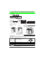
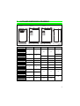
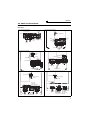
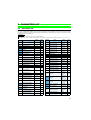
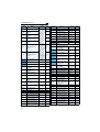
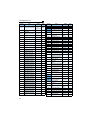
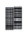
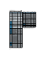
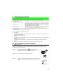
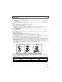
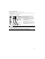
INVERTER FR-A700 INSTALLATION GUIDELINE FR-A740-00023 to 12120-EC Thank you for choosing this Mitsubishi Inverter. Please read through this Installation Guideline and a CD-ROM enclosed to operate this inverter correctly. Do not use this product until you have a full knowledge of the equipment, safety information and instructions. Please forward this Installation Guideline and the CD-ROM to the end user. 1 CONTENTS INSTALLATION OF THE INVERTER AND INSTRUCTIONS................. 1 2 OUTLINE DIMENSION DRAWING ......................................................... 2 3 WIRING.................................................................................................... 3 4 PRECAUTIONS FOR USE OF THE INVERTER..................................... 8 5 PARAMETER LIST................................................................................ 10 6 TROUBLESHOOTING........................................................................... 18 700 This section is specifically about safety matters CAUTION (2) Wiring Do not attempt to install, operate, maintain or inspect the inverter until you have read through this Installation Guideline and appended documents carefully and can use the equipment correctly. Do not use the inverter until you have a full knowledge of the equipment, safety information and instructions. In this Installation Guideline, the safety instruction levels are classified into "WARNING" and "CAUTION". Assumes that incorrect handling may cause hazardous conditions, resulting in death or severe injury. Assumes that incorrect handling may cause hazardous conditions, resulting in medium or slight injury, or may cause physical damage only. • Do not install a power factor correction capacitor or surge suppressor/radio noise filter (capacitor type filter) on the inverter output side. • The connection orientation of the output cables U, V, W to the motor will affect the direction of rotation of the motor. CAUTION level may lead to a serious consequence Note that even the according to conditions. Please follow strictly the instructions of both levels because they are important to personnel safety. • When you have chosen the retry function, stay away from the equipment as it will restart suddenly after an alarm stop. WARNING CAUTION 1. Electric Shock Prevention WARNING • While power is on or when the inverter is running, do not open the front cover. Otherwise you may get an electric shock. • Do not run the inverter with the front cover or wiring cover removed. Otherwise, you may access the exposed high-voltage terminals or the charging part of the circuitry and get an electric shock. • Even if power is off, do not remove the front cover except for wiring or periodic inspection.You may access the charged inverter circuits and get an electric shock. • Before starting wiring or inspection, check to make sure that the operation panel indicator is off, wait for at least 10 minutes after the power supply has been switched off, and check that there are no residual voltage using a tester or the like. The capacitor is charged with high voltage for some time after power off and it is dangerous. • This inverter must be earthed (grounded). Earthing (Grounding) must conform to the requirements of national and local safety regulations and electrical codes. (NEC section 250, IEC 536 class 1 and other applicable standards) • Any person who is involved in the wiring or inspection of this equipment should be fully competent to do the work. • Always install the inverter before wiring. Otherwise, you may get an electric shock or be injured. • Perform setting dial and key operations with dry hands to prevent an electric shock. Otherwise you may get an electric shock. • Do not subject the cables to scratches, excessive stress, heavy loads or pinching. Otherwise you may get an electric shock. • Do not replace the cooling fan while power is on. It is dangerous to replace the cooling fan while power is on. • Do not touch the printed circuit board with wet hands. You may get an electric shock. • When measuring the main circuit capacitor capacity, the DC voltage is applied to the motor for 1s at powering off. Never touch the motor terminal, etc. right after powering off to prevent an electric shock. 2. Fire Prevention CAUTION • Install the inverter on an incombustible wall without holes, etc. Mounting it to or near combustible material can cause a fire. • If the inverter has become faulty, switch off the inverter power. A continuous flow of large current could cause a fire. • When using a brake resistor, make up a sequence that will turn off power when an alarm signal is output. Otherwise, the brake resistor may excessively overheat due to damage of the brake transistor and such, causing a fire. • Do not connect a resistor directly to the DC terminals P/+, N/−. This could cause a fire. 3. Injury Prevention CAUTION • Apply only the voltage specified in the instruction manual to each terminal. Otherwise, burst, damage, etc. may occur. • Ensure that the cables are connected to the correct terminals. Otherwise, burst, damage, etc. may occur. • Always make sure that polarity is correct to prevent damage, etc. Otherwise, burst, damage, etc. may occur. • While power is on or for some time after power-off, do not touch the inverter as it is hot and you may get burnt. 4. Additional Instructions Also note the following points to prevent an accidental failure, injury, electric shock, etc. (3) Test operation and adjustment CAUTION • Before starting operation, confirm and adjust the parameters. A failure to do so may cause some machines to make unexpected motions. WARNING (4) Operation • Since the • • • • • key is valid only when functions are set (refer to the Instruction Manual ), provide a circuit and switch separately to make an emergency stop (power off, mechanical brake operation for emergency stop, etc). Make sure that the start signal is off before resetting the inverter alarm. A failure to do so may restart the motor suddenly. The load used should be a three-phase induction motor only. Connection of any other electrical equipment to the inverter output may damage the inverter as well as equipment. Performing pre-excitation (LX signal and X13 signal) under torque control (real sensorless vector control) may start the motor running at a low speed even when the start command (STF or STR) is not input. The motor may run also at a low speed when the speed limit value = 0 with a start command input. Perform pre-excitation after making sure that there will be no problem in safety if the motor runs. Do not modify the equipment. Do not perform parts removal which is not instructed in manuals. Doing so may lead to fault or damage of the inverter. CAUTION • The electronic thermal relay function does not guarantee protection of the motor from overheating. • Do not use a magnetic contactor on the inverter input for frequent starting/ stopping of the inverter. • Use a noise filter to reduce the effect of electromagnetic interference. Otherwise nearby electronic equipment may be affected. • Take measures to suppress harmonics. Otherwise power supply harmonics from the inverter may heat/damage the power factor correction capacitor and generator. • When a 400V class motor is inverter-driven, please use an insulation-enhanced motor or measures taken to suppress surge voltages. Surge voltages attributable to the wiring constants may occur at the motor terminals, deteriorating the insulation of the motor. • When a 600V class motor is inverter-driven, it should be insulation-enhanced or surge voltages suppressed. Surge voltages attributable to the wiring constants may occur at the motor terminals, deteriorating the insulation of the motor. • When parameter clear or all clear is performed, reset the required parameters before starting operations. Each parameter returns to the initial value. • The inverter can be easily set for high-speed operation. Before changing its setting, fully examine the performances of the motor and machine. • In addition to the inverter's holding function, install a holding device to ensure safety. • Before running an inverter which had been stored for a long period, always perform inspection and test operation. • For prevention of damage due to static electricity, touch nearby metal before touching this product to eliminate static electricity from your body. (5) Emergency stop (6) Maintenance, inspection and parts replacement CAUTION (1) Transportation and installation CAUTION Environment • When carrying products, use correct lifting gear to prevent injury. • Do not stack the inverter boxes higher than the number recommended. • Ensure that installation position and material can withstand the weight of the inverter. Install according to the information in the instruction manual. • Do not install or operate the inverter if it is damaged or has parts missing. This can result in breakdowns. • When carrying the inverter, do not hold it by the front cover or setting dial; it may fall off or fail. • Do not stand or rest heavy objects on the product. • Check the inverter mounting orientation is correct. • Prevent other conductive bodies such as screws and metal fragments or other flammable substance such as oil from entering the inverter. • As the inverter is a precision instrument, do not drop or subject it to impact. • Use the inverter under the following environmental conditions. Otherwise, the inverter may be damaged. LD, ND (initial Ambient setting), HD temperature SLD Ambient humidity Storage temperature CAUTION • Provide a safety backup such as an emergency brake which will prevent the machine and equipment from hazardous conditions if the inverter fails. • When the breaker on the inverter input side trips, check for the wiring fault (short circuit), damage to internal parts of the inverter, etc. Identify the cause of the trip, then remove the cause and power on the breaker. • When the protective function is activated, take the corresponding corrective action, then reset the inverter, and resume operation. • Do not carry out a megger (insulation resistance) test on the control circuit of the inverter. (7) Disposing of the inverter • Treat as industrial waste. CAUTION General instructions Many of the diagrams and drawings in instruction manuals show the inverter without a cover, or partially open. Never run the inverter in this status. Always replace the cover and follow instruction manuals when operating the inverter. -10°C to +50°C (non-freezing) -10°C to +40°C (non-freezing) 90% RH or less (non-condensing) -20°C to +65°C *1 Indoors (free from corrosive gas, flammable gas, oil Atmosphere mist, dust and dirt) Maximum 1000m above sea level for standard operation. After that derate by 3% for every extra 500m Altitude, vibration up to 2500m (92%) 5.9m/s2 or less *2 *1 Temperature applicable for a short time, e.g. in transit. *2 2.9m/s2 or less for the 04320 or more. A-1 INSTALLATION OF THE INVERTER AND INSTRUCTIONS 1 INSTALLATION OF THE INVERTER AND INSTRUCTIONS • Inverter Type FR - A740 - 00126 - EC Symbol A740 Voltage Class Three-phase 400V class Symbol 00023 to 12120 Type number Displays the rated current Rating plate Inverter type Capacity plate Capacity plate Rating plate Input rating Inverter type FR-A740-00126-EC Output rating FR-A740-00126-EC ND (50 C) XXA Serial number LD (50 C) XXA HD (50 C) XXA SLD (40 C) XXA Serial number SLD LD ND HD Overload current rating Ambient temperature 110% 60s, 120% 3s 40 C (104 F) 120% 60s, 150% 3s 50 C (122 F) 150% 60s, 200% 3s 50 C (122 F) 200% 60s, 250% 3s 50 C (122 F) • Installation of the inverter Installation on the enclosure 00620 or less 00770 or more CAUTION • When encasing multiple inverters, install them in parallel as a cooling measure. • Install the inverter vertically. 10cm or more *2 Vertic 10cm or more *2 Fix six positions for the FR-A740-04320 to 08660 and fix eight positions for the FR-A740-09620 to 12120. 5cm or more *1 *1 1cm or more for 00126 or less 10cm or more for 02160 or more *2 20cm or more for 02160 or more • General Precaution The bus capacitor discharge time is 10 minutes. Before starting wiring or inspection, switch power off, wait for more than 10 minutes, and check for residual voltage between terminal P/+ and N/- with a meter etc., to avoid a hazard of electrical shock. • Environment Before installation, check that the environment meets following specifications. LD, ND (initial setting),HD: -10°C to + 50°C (non-freezing) SLD: -10°C to + 40°C (non-freezing) Ambient temperature Measurement position 5cm Measurement position Ambient humidity Storage temperature Ambience Altitude, vibration 90%RH or less (non-condensing) -20°C to + 65°C Indoors (No corrosive and flammable gases, oil mist, dust and dirt.) Below 1000m, 5.9m/s2 or less (2.9m/s2 or less for the 04320 or more) CAUTION • • • • 1 Install the inverter on a strong surface securely and vertically with bolts. Leave enough clearances and take cooling measures. Avoid places where the inverter is subjected to direct sunlight, high temperature and high humidity. Install the inverter on a non-combustible wall surface. Inverter 5cm 5cm OUTLINE DIMENSION DRAWING 2 OUTLINE DIMENSION DRAWING H1 H FR-A740-09620 to 12120-EC W1 W W1 W1 H1 H FR-A740-04320 to 08660-EC H1 H FR-A740-00023 to 03610-EC W1 W W1 W W1 D (Unit:mm) Inverter Type FR-A740-00023-EC FR-A740-00038-EC FR-A740-00052-EC FR-A740-00083-EC FR-A740-00126-EC FR-A740-00170-EC FR-A740-00250-EC FR-A740-00310-EC FR-A740-00380-EC FR-A740-00470-EC FR-A740-00620-EC FR-A740-00770-EC FR-A740-00930-EC FR-A740-01160-EC FR-A740-01800-EC FR-A740-02160-EC FR-A740-02600-EC FR-A740-03250-EC FR-A740-03610-EC FR-A740-04320-EC FR-A740-04810-EC FR-A740-05470-EC FR-A740-06100-EC FR-A740-06830-EC FR-A740-07700-EC FR-A740-08660-EC FR-A740-09620-EC FR-A740-10940-EC FR-A740-12120-EC W W1 150 125 H H1 260 245 D 140 170 220 195 300 285 190 250 230 400 380 190 325 270 550 530 195 435 380 550 525 250 620 595 300 465 400 740 715 360 1010 985 380 498 200 680 300 790 315 1330 1300 995 300 1580 1550 440 2 Terminal connection diagram 3 WIRING 3.1 Terminal connection diagram Control circuit terminal *1. DC reactor (FR-HEL) Be sure to connect the DC reactor supplied with the 01800 or more. When a DC reactor is connected to the 01160 or less, remove the jumper across P1-P/+. R *8 Earth (Ground) P/+ P1 *2 Earth (Ground) Low speed Jog mode Output stop Reset Terminal 4 input selection (Current input selection) Selection of automatic restart after instantaneous power failure Contact input common (Sink) (Common for external power supply transistor) 24VDC power supply Contact input common (Refer to the Instruction Manual) EMC filter ON/OFF connecter Motor IM Earth (Ground) 1 A1 (Refer to the Instruction Manual) C2 RH B2 RM Relay output 2 A2 RL JOG *3 Open collector output RUN Running RT SU MRS IPF RES *4 OL AU Terminal functions Up to frequency vary with the output terminal assignment Instantaneous (Pr. 190 to Pr. 194) power failure (Refer to the Instruction Manual) Overload FU AU Frequency detection CS PTC SD SE PC *5 Voltage/current 4 Connector for plug-in option connection Terminal functions Relay output 1 vary with the output (Alarm output) terminal assignment (Pr. 195, Pr. 196) STR input switch 4 2 ON OFF 0 to ±10VDC (Initial value) 1 0 to ±5VDC selected *5 Auxiliary (+) input (-) Terminal 4 input (+) (Current (-) input) Relay output B1 STOP 10(+5V) 0 to 5VDC (Initial value) 2 0 to 10VDC selected *5 0 to 20mADC 5 (Analog common) 2 C1 STF 10E(+10V) 3 *6. It is recommended to use 2W1kΩ when the frequency setting signal is changed frequently. U V W Control circuit (Common for external power supply transistor) Frequency setting signal (Analog) *5. Terminal input specifications can be changed by analog input specifications switchover (Pr. 73, Pr. 267). Set the voltage/current input switch in the OFF position to select voltage input (0 to 5V/0 to10V) and ON to select current input (4 to 20mA). OFF SOURCE Middle speed Second function selection Frequency setting potentiometer 1/2W1kΩ *6 N/- CN8 *7 Main circuit Control input signals (No voltage input allowed) Forward Terminal functions vary with rotation the input terminal start assignment (Pr. 178 to Pr. 189) Reverse rotation (Refer to the Instruction start Manual) Start selfholding selection High speed *4. AU terminal can be used as PTC input terminal. ON R1/L11 S1/L21 Jumper *3. JOG terminal can be used as pulse train input terminal. Use Pr.291 to select JOG/pulse. PR *7. A CN8 connector is provided with the 02160 or more. *8. Brake resistor (FR-ABR) Remove the jumper across terminal PR-PX when connecting a brake resistor. (00023 to 00250) Terminal PR is provided for the 00023 to 00620. Install a thermal relay to prevent an overheat and burnout of the brake resistor. (Refer to the Instruction Manual) R/L1 S/L2 T/L3 Multi-speed selection PX R Three-phase AC power supply *2. To supply power to the control circuit separately, remove the jumper across R1/L11 and S1/L21. Jumper Jumper MC MCCB Brake unit (Option) *1 SINK Source logic Main circuit terminal 4 to 20mADC (Initial value) 0 to 5VDC selected *5 0 to 10VDC Option connector 1 Option connector 2 Option connector 3 Open collector output common Sink/source common *10. It is not necessary when calibrating the indicator from the operation panel. PU connector USB CA connector (+) (-) AM 5 TXD+ TXD- (+) (-) Analog current output (0 to 20mADC) Analog signal output (0 to 10VDC) RS-485 terminals Data transmission RXD+ RXD- Data reception SG GND Terminating resistor VCC 5V (Permissible load current 100mA) CAUTION · · · 3 To prevent a malfunction due to noise, keep the signal cables more than 10cm away from the power cables. After wiring, wire offcuts must not be left in the inverter. Wire offcuts can cause an alarm, failure or malfunction. Always keep the inverter clean. When drilling mounting holes in an enclosure etc., take care not to allow chips and other foreign matter to enter the inverter. Set the voltage/current input switch correctly. Different setting may cause a fault, failure or malfunction. WIRING 3.2 Main circuit terminal (1) Terminal layout and wiring 400V class FR-A740-00023 to 00126-EC FR-A740-00170, 00250-EC Jumper Screw size (M4) Jumper R/L1 S/L2 T/L3 P/+ N/- Charge lamp PR PX R1/L11 S1/L21 N/- Jumper Screw size (M4) IM Power supply P/+ PR Jumper R1/L11 S1/L21 Charge lamp Screw size (M4) Motor PX R/L1 S/L2 T/L3 IM Motor Power supply Screw size (M4) FR-A740-00310, 00380-EC FR-A740-00470, 00620-EC R1/L11 S1/L21 Screw size (M4) R1/L11 S1/L21 Screw size (M4) Charge lamp Jumper Charge lamp PR Jumper Screw size (M6) Jumper P/+ Screw size (M5) N/- R/L1 S/L2 T/L3 R/L1 S/L2 T/L3 N/- P/+ IM PR Power supply Jumper Motor IM Screw size (M6) Motor Power supply Screw size (M5) FR-A740-00770, 00930, 01160-EC FR-A740-01800-EC R1/L11 S1/L21 Screw size(M4) R1/L11 S1/L21 Charge lamp Screw size (M4) Charge lamp Jumper Jumper Screw size (00770: M6 00930, 01160: M8) Screw size (M8) R/L1 S/L2 T/L3 R/L1 S/L2 T/L3 Power supply N/- N/- IM Motor Power supply Screw size (M8) P/+ P/+ P/+ Jumper Screw size (00770: M6 00930/01160: M8) Screw size (M10) IM Motor DC reactor Screw size (M8) 4 WIRING FR-A740-02160, 02600-EC FR-A740-03250, 03610-EC R1/L11 S1/L21 Screw size (M4) Charge lamp R1/L11 S1/L21 Screw size (M4) Jumper Charge lamp Jumper Screw size (M10) Screw size(M10) N/- R/L1 S/L2 T/L3 P/+ P/+ N/- R/L1 S/L2 T/L3 P/+ Screw size (M10) P/+ Power supply P/+ IM Motor DC reactor Screw size (M10) FR-A740-04320, 04810-EC Power supply Screw size (M12) (for option) IM Motor DC reactor FR-A740-05470 to 12120-EC R1/L11 S1/L21 Screw size (M4) R1/L11 S1/L21 Screw size (M4) Charge lamp Charge lamp Jumper Jumper Screw size (M12) R/L1 S/L2 T/L3 N/- P/+ P/+ Screw size (M12) R/L1 S/L2 T/L3 N/- Screw size (M10) P/+ Power supply Screw size (M12) (for option) P/+ IM Motor P/+ DC reactor IM Motor Power supply DC reactor Screw size (M10) CAUTION · The power supply cables must be connected to R/L1, S/L2, T/L3. Never connect the power cable to the U, V, W of the inverter. Doing so will damage the inverter. (Phase sequence needs not to be matched.) · Connect the motor to U, V, W. At this time, turning on the forward rotation switch (signal) rotates the motor in the counterclockwise direction when viewed from the motor shaft. · When wiring the inverter main circuit conductor of the 05470 or more, tighten a nut from the right side of the conductor. When wiring two wires, place wires on both sides of the conductor. (Refer to the drawing below.) For wiring, use bolts (nuts) provided with the inverter. 5 WIRING (2) Applied cable size Select the recommended cable size to ensure that a voltage drop will be 2% max. If the wiring distance is long between the inverter and motor, a main circuit cable voltage drop will cause the motor torque to decrease especially at the output of a low frequency. The following table indicates a selection example for the wiring length of 20m. 400V class (when input power supply is 440V) Applicable Inverter Type FR-A740-00023 to 00126-EC FR-A740-00170-EC FR-A740-00250-EC FR-A740-00310-EC FR-A740-00380-EC FR-A740-00470-EC FR-A740-00620-EC FR-A740-00770-EC FR-A740-00930-EC FR-A740-01160-EC FR-A740-01800-EC FR-A740-02160-EC FR-A740-02600-EC FR-A740-03250-EC FR-A740-03610-EC FR-A740-04320-EC FR-A740-04810-EC FR-A740-05470-EC FR-A740-06100-EC FR-A740-06830-EC FR-A740-07700-EC FR-A740-08660-EC FR-A740-09620-EC FR-A740-10940-EC FR-A740-12120-EC *1 *2 *3 *4 Terminal Tightening Screw Torque Size *4 N·m Cable Sizes Crimping Terminal R/L1, S/L2, T/L3 U, V, W HIV, etc. (mm2) *1 R/L1, S/L2, T/L3 U, V, W M4 1.5 2-4 2-4 2 2 M4 M4 M5 M5 M6 M6 M6 M8 M8 M8 M10 M10 M10-M12 M10-M12 M12-M10 M12-M10 M12-M10 M12-M10 M12-M10 M12-M10 M12-M10 M12-M10 M12-M10 M12-M10 1.5 1.5 2.5 2.5 4.4 4.4 4.4 7.8 7.8 7.8 14.7 14.7 14.7 14.7 24.5 24.5 24.5 24.5 24.5 24.5 24.5 24.5 24.5 24.5 2-4 5.5-4 5.5-5 8-5 14-6 14-6 22-6 22-8 38-8 60-8 60-10 60-10 80-10 100-10 150-12 150-12 100-12 100-12 150-12 150-12 C2-200 C2-200 C2-250 C2-200 2-4 5.5-4 5.5-5 8-5 8-6 14-6 22-6 22-8 38-8 60-8 60-10 60-10 80-10 100-10 150-12 150-12 100-12 100-12 150-12 150-12 C2-200 C2-200 C2-250 C2-250 2 3.5 5.5 8 14 14 22 22 38 60 60 60 80 100 125 150 2×100 2×100 2×125 2×150 2×200 2×200 2×250 3×200 2 3.5 5.5 8 8 14 22 22 38 60 60 60 80 100 150 150 2×100 2×100 2×125 2×150 2×200 2×200 2×250 2×250 AWG/MCM *2 PVC, etc. (mm2) *3 R/L1, Earth R/L1, Earth P/+, P1 (Ground) S/L2, U, V, W S/L2, U, V, W (Ground) T/L3 Cable T/L3 Cable 2 2 3.5 3.5 3.5 3.5 5.5 8 8 8 14 14 22 14 22 14 22 14 38 22 60 22 60 38 80 38 80 38 100 38 150 38 150 38 2×100 60 2×125 60 2×125 60 2×150 100 2×200 100 2×200 100 2×250 100 3×200 2×100 14 14 2.5 12 12 10 8 6 6 4 4 1 1/0 1/0 3/0 3/0 4/0 250 300 2×4/0 2×4/0 2×250 2×300 2×350 2×400 2×500 2×500 14 12 10 8 8 6 4 4 2 1/0 1/0 3/0 3/0 4/0 250 300 2×4/0 2×4/0 2×250 2×300 2×350 2×400 2×500 2×500 2.5 4 6 10 16 16 25 25 50 50 50 50 70 95 120 150 2×95 2×95 2×120 2×150 2×185 2×185 2×240 2×240 2.5 2.5 2.5 4 4 4 6 10 10 10 10 16 16 16 25 16 25 16 50 25 50 25 50 25 50 25 70 35 95 50 120 70 150 95 2×95 95 2×95 95 2×120 120 2×150 150 2×185 2×95 2×185 2×95 2×240 2×120 2×240 2×120 For the 01800 or less, the cable size is that of the cable (HIV cable (600V class 2 vinyl-insulated cable) etc.) with continuous maximum permissible temperature of 75°C. Assumes that the ambient temperature is 50°C or less and the wiring distance is 20m or less. For the 02160 or more, the recommended cable size is that of the cable (LMFC (heat resistant flexible cross-linked polyethylene insulated cable) etc.) with continuous maximum permissible temperature of 90°C. Assumes that the ambient temperature is 50°C or less and wiring is performed in an enclosure. For the 01160 or less, the recommended cable size is that of the cable (THHW cable) with continuous maximum permissible temperature of 75°C. Assumes that the ambient temperature is 40°C or less and the wiring distance is 20m or less. For the 01800 or more, the recommended cable size is that of the cable (THHN cable) with continuous maximum permissible temperature of 90°C. Assumes that the ambient temperature is 40°C or less and wiring is performed in an enclosure. (Selection example for use mainly in the United States.) For the 01160 or less, the recommended cable size is that of the cable (PVC cable) with continuous maximum permissible temperature of 70°C. Assumes that the ambient temperature is 40°C or less and the wiring distance is 20m or less. For the 01800 or more, the recommended cable size is that of the cable (XLPE cable) with continuous maximum permissible temperature of 90°C. Assumes that the ambient temperature is 40°C or less and wiring is performed in an enclosure. (Selection example for use mainly in Europe.) The terminal screw size indicates the terminal size for R/L1, S/L2, T/L3, U, V, W, and a screw for earthing (grounding). For the 03250 and 03610, screw sizes are different (<R/L1, S/L2, T/L3, U, V, W, a screw for earthing (grounding)> - <P/+ for option connection>) For the 04320 or more, screw sizes are different. (<R/L1, S/L2, T/L3, U, V, W> - <a screw for earthing (grounding)>) The line voltage drop can be calculated by the following formula: line voltage drop [V]= 3 × wire resistance[mΩ/m] × wiring distance[m] × current[A] 1000 Use a larger diameter cable when the wiring distance is long or when it is desired to decrease the voltage drop (torque reduction) in the low speed range. CAUTION · Tighten the terminal screw to the specified torque. A screw that has been tighten too loosely can cause a short circuit or malfunction. A screw that has been tighten too tightly can cause a short circuit or malfunction due to the unit breakage. · Use crimping terminals with insulation sleeve to wire the power supply and motor. 6 WIRING (3) Total wiring length (FR-A720/A740) The overall wiring length for connection of a single motor or multiple motors should be within the value in the table below. (The wiring length should be 100m maximum for vector control.) Pr. 72 PWM frequency selection setting (carrier frequency) * 2 (2kH) or less 3 (3kHz), 4 (4kHz) 5 (5kHz) to 9 (9kHz) 10 (10kHz) or more 00023 00038 300m 200m 500m 300m 100m 50m 00052 or more 500m 500m When driving a 400V class motor by the inverter, surge voltages attributable to the wiring constants may occur at the motor terminals, deteriorating the insulation of the motor. Take the following measures 1) or 2) in this case. 1) Use a "400V class inverter-driven insulation-enhanced motor". 2) Connect the surge voltage suppression filter (FR-ASF-H) to the 01800 or less and the sine wave filter (MT-BSL/ BSC) to the 02160 or more on the inverter output side. CAUTION · Especially for long-distance wiring, the inverter may be affected by a charging current caused by the stray capacitances of the wiring, leading to a malfunction of the overcurrent protective function or fast response current limit function or a malfunction or fault of the equipment connected on the inverter output side. If fast response current limit function malfunctions, disable this function. (For Pr. 156 Stall prevention operation selection, refer to Instruction Manual.) · For details of Pr. 72 PWM frequency selection , refer to Instruction Manual. (When using an option sine wave filter (MT-BSL/BSC) for the 02160 or more, set "25" (2.5kHz) in Pr. 72.) For explanation of surge voltage suppression filter (FR-ASF-H) and sine wave filter (MT-BSL/BSC), refer to the manual of each option. · Do not perform vector control with a surge voltage suppression filter (FR-ASF-H) or sine wave filer (MT-BSL/BSC) connected. (4) Cable size of the control circuit power supply (terminal R1/L11, S1/L21) · Terminal screw size: M4 · Cable size: 0.75mm2 to 2mm2 · Tightening torque: 1.5N·m 3.3 Control circuit terminals (1) Terminal layout CA A1 B1 C1 PC AM 10E 10 A2 B2 2 C2 5 RL 4 RM RH 1 RT SD PC AU STOP RES STF STR PC SE RUN SU IPF OL FU MRS JOG CS (2) Instructions for wiring of the control circuit terminal 1) 2) 3) 4) 5) 6) 7) 7 Terminals 5, PC and SE are common to the I/O signals and isolated from each other. Do not earth (ground). Avoid connecting the terminal PC and 5 and the terminal SE and 5. Use shielded or twisted cables for connection to the control circuit terminals and run them away from the main and power circuits (including the 200V relay sequence circuit). Use two or more parallel micro-signal contacts or twin contacts to prevent a contact faults when using contact inputs since the control circuit input signals are micro-currents. Micro signal contacts Twin contacts Do not apply a voltage to the contact input terminals (e.g. STF) of the control circuit. Always apply a voltage to the alarm output terminals (A, B, C) via a relay coil, lamp, etc. It is recommended to use the cables of 0.75mm2 gauge for connection to the control circuit terminals. If the cable gauge used is 1.25mm2 or more, the front cover may be lifted when there are many cables running or the cables are run improperly, resulting in an operation panel contact fault. The wiring length should be 30m maximum. PRECAUTIONS FOR USE OF THE INVERTER 4 PRECAUTIONS FOR USE OF THE INVERTER The FR-A700 series is a highly reliable product, but incorrect peripheral circuit making or operation/handling method may shorten the product life or damage the product. Before starting operation, always recheck the following items. (1) Use crimping terminals with insulation sleeve to wire the power supply and motor. (2) Application of power to the output terminals (U, V, W) of the inverter will damage the inverter. Never perform such wiring. (3) After wiring, wire offcuts must not be left in the inverter. Wire offcuts can cause an alarm, failure or malfunction. Always keep the inverter clean. When drilling mounting holes in an enclosure etc., take care not to allow chips and other foreign matter to enter the inverter. (4) Use cables of the size to make a voltage drop 2% maximum. If the wiring distance is long between the inverter and motor, a main circuit cable voltage drop will cause the motor torque to decrease especially at the output of a low frequency. Refer to page 6 for the recommended cable sizes. (5) The overall wiring length should be 500m maximum. (The wiring length should be 100m maximum for vector control.) Especially for long distance wiring, the fast response current limit function may decrease or the equipment connected to the secondary side may malfunction or become faulty under the influence of a charging current due to the stray capacity of the wiring. Therefore, note the overall wiring length. (Refer to page 7.) (6) Electromagnetic wave interference The input/output (main circuit) of the inverter includes high frequency components, which may interfere with the communication devices (such as AM radios) used near the inverter. An EMC filter can minimize noise interference. (7) Do not install a power factor correction capacitor, surge suppressor or radio noise filter on the inverter output side. This will cause the inverter to trip or the capacitor, and surge suppressor to be damaged. If any of the above devices is installed, immediately remove it. (8) Before starting wiring or other work after the inverter is operated, wait for at least 10 minutes after the power supply has been switched off, and check that there are no residual voltage using a tester or the like. The capacitor is charged with high voltage for some time after power off and it is dangerous. (9) A short circuit or earth (ground) fault on the inverter output side may damage the inverter modules. · Fully check the insulation resistance of the circuit prior to inverter operation since repeated short circuits caused by peripheral circuit inadequacy or an earth (ground) fault caused by wiring inadequacy or reduced motor insulation resistance may damage the inverter modules. · Fully check the to-earth (ground) insulation and inter-phase insulation of the inverter output side before power-on. Especially for an old motor or use in hostile atmosphere, securely check the motor insulation resistance etc. (10) Do not use the inverter input side magnetic contactor to start/stop the inverter. Always use the start signal (ON/OFF of STF and STR signals) to start/stop the inverter. (11) Across P/+ and PR terminals, connect only an external regenerative brake discharge resistor. Do not connect a mechanical brake. (12) Do not apply a voltage higher than the permissible voltage to the inverter I/O signal circuits. Application of permissible voltage to the inverter I/O signal circuit and incorrect polarity may damage the I/O terminal. Especially check the wiring to prevent the speed setting potentiometer from being connected incorrectly to short terminals 10E-5. 8 PRECAUTIONS FOR USE OF THE INVERTER (13) Provide electrical and mechanical interlocks for MC1 and MC2 which are used for bypass operation. When the wiring is incorrect or if there is an electronic bypass circuit as shown on the right, the inverter will be damaged by leakage current from the power supply due to arcs generated at the time of switch-over or chattering caused by a sequence error. (Commercial operation can not be performed with the vector dedicated motor (SF-V5RU, SF-THY).) MC1 Power supply Interlock R/L1 U IM S/L2 V MC2 T/L3 W Undesirable current Inverter (14) If the machine must not be restarted when power is restored after a power failure, provide a magnetic contactor in the inverter's input side and also make up a sequence which will not switch on the start signal. If the start signal (start switch) remains on after a power failure, the inverter will automatically restart as soon as the power is restored. (15) Instructions for overload operation When performing an operation of frequent start/stop with the inverter, rise/fall in the temperature of the transistor element of the inverter will repeat due to a continuous flow of large current, shortening the life from thermal fatigue. Since thermal fatigue is related to the amount of current, the life can be increased by reducing current at locked condition, starting current, etc. Decreasing current may increase the life. However, decreasing current will result in insufficient torque and the inverter may not start. Therefore, choose the inverter which has enough allowance for current (up to 2 rank larger in capacity). (16) Make sure that the specifications and rating match the system requirements. (17) A motor with encoder is necessary for vector control. In addition, connect the encoder directly to the backlash-free motor shaft. An encoder is not necessary for real sensorless vector control. 9 PARAMETER LIST 5 PARAMETER LIST 5.1 Parameter list For simple variable-speed operation of the inverter, the initial setting of the parameters may be used as they are. Set the necessary parameters to meet the load and operational specifications. Parameter setting, change and check can be made from the operation panel (FR-DU07). REMARKS ⋅ indicates simple mode parameters. (initially set to extended mode) ⋅ The shaded parameters in the table allow its setting to be changed during operation even if "0" (initial value) is set in Pr.77 Parameter write selection. Parameter 0 Name Torque boost Setting Range 0 to 30% 31 Frequency jump 1A 32 Frequency jump 1B 33 Frequency jump 2A 34 Frequency jump 2B 35 Frequency jump 3A 36 Frequency jump 3B 37 41 42 Speed display Up-to-frequency sensitivity Output frequency detection 43 Output frequency detection for reverse rotation 44 Second acceleration/ deceleration time 0 to 3600/360s 45 Second deceleration time 0 to 3600/ 360s, 9999 9999 46 Second torque boost 0 to 30%, 9999 9999 47 Second V/F (base frequency) 0 to 400Hz, 9999 9999 48 Second stall prevention operation current 0 to 220% 150% 49 Second stall prevention operation frequency 0 to 400Hz, 9999 0Hz 0.5s 50 Second output frequency detection 0 to 400Hz 30Hz 0 120/ 60Hz *2 51 Second electronic thermal O/L relay 52 DU/PU main display data selection 54 CA terminal function selection 55 Frequency monitoring reference Maximum frequency 0 to 120Hz 2 3 Minimum frequency 0 to 120Hz 0Hz Base frequency 0 to 400Hz 50Hz 4 Multi-speed setting (high speed) Multi-speed setting (middle speed) Multi-speed setting (low speed) 6 0 to 400Hz 50Hz 0 to 400Hz 30Hz 0 to 400Hz 10Hz 7 8 Acceleration time 0 to 3600/360s 5/15s *3 Deceleration time 0 to 3600/360s 5/15s *3 9 Electronic thermal O/L relay 0 to 500/ 0 to 3600A *2 Rated inverter current 0 to 120Hz, 9999 13 14 DC injection brake operation frequency DC injection brake operation time DC injection brake operation voltage Starting frequency Load pattern selection 0 to 60Hz 0 to 5 0.5Hz 0 15 Jog frequency 0 to 400Hz 5Hz 16 Jog acceleration/ deceleration time 10 11 12 17 18 MRS input selection High speed maximum frequency 0.5s 0 to 30% 4/2/ 1%*4 0, 2, 4 120 to 400Hz 19 Base frequency voltage 0 to 1000V, 8888, 9999 20 Acceleration/deceleration reference frequency 1 to 400Hz 21 Acceleration/deceleration time increments 0, 1 22 Stall prevention operation level (torque limit level ) Stall prevention operation level compensation factor at double speed 3Hz 0 to 10s, 8888 0 to 3600/360s 8888 50Hz 0 0 to 400% 150% 0 to 200%, 9999 9999 Multi-speed setting (4 speed to 7 speed) 0 to 400Hz, 9999 9999 0, 1 0 29 Multi-speed input compensation selection Acceleration/deceleration pattern selection 0 to 5 0 30 Regenerative function selection 0, 1, 2, 10, 11, 20, 21 0 23 24 to 27 28 Initial Value Parameter 1 5 Setting Range Initial Value 6/4/3/2/ 1% *1 120/ 60Hz *2 Name 0 to 400Hz, 9999 0 to 400Hz, 9999 0 to 400Hz, 9999 0 to 400Hz, 9999 0 to 400Hz, 9999 0 to 400Hz, 9999 0, 1 to 9998 0 to 100% 0 to 400Hz 0 to 400Hz, 9999 0 to 500A, 9999/ 0 to 3600A, 9999 *2 0, 5 to 14, 17 to 20, 22 to 25, 32 to 35, 50 to 57, 100 1 to 3, 5 to 14, 17, 18, 21, 24, 32 to 34, 50, 52, 53, 70 0 to 400Hz 56 Current monitoring reference 0 to 500/0 to 3600A *2 57 Restart coasting time 58 Restart cushion time 0, 0.1 to 5s, 9999/ 0, 0.1 to 30s, 9999 *2 0 to 60s 59 Remote function selection 0, 1, 2, 3 9999 9999 9999 9999 9999 9999 0 10% 6Hz 9999 5s 9999 0 1 50Hz Rated inverter current 9999 1s 0 10 PARAMETER LIST Parameter Setting Range Name Initial Value Energy saving control selection 0, 4 61 Reference current 0 to 500A, 9999/ 0 to 3600A, 9999 *2 9999 62 Reference value at acceleration 0 to 220%, 9999 9999 63 Reference value at deceleration 0 to 220%, 9999 9999 64 Starting frequency for elevator mode 0 to 10Hz, 9999 9999 65 Retry selection 0 to 5 66 Stall prevention operation reduction starting frequency 0 to 400Hz 50Hz 67 Number of retries at alarm occurrence 0 to 10, 101 to 110 0 68 Retry waiting time 0 to 10s 69 Retry count display erase 0 70 Special regenerative brake duty 0 to 30%/ 0 to 10% *2 Applied motor 0 to 8, 13 to 18, 20, 23, 24, 30, 33, 34, 40, 43, 44, 50, 53, 54 60 71 92 Motor constant (L1) Setting Range 0 to 50Ω (0 to 1000mH), 9999/ 0 to 3600mΩ (0 to 400mH), 9999 Initial Value 9999 *2 93 Motor constant (L2) 0 to 50Ω (0 to 1000mH), 9999/ 0 to 3600mΩ (0 to 400mH), 9999 9999 *2 0 to 500Ω (0 to 100%), 9999/ 0 to 100Ω (0 to 100%), 9999 94 Motor constant (X) 95 Online auto tuning selection 0 to 2 96 Auto tuning setting/status 0, 1, 101 100 V/F1(first frequency) 0 to 400Hz, 9999 1s 101 V/F1(first frequency voltage) 0 to 1,000V 0V 0 102 V/F2(second frequency) 0 to 400Hz, 9999 9999 103 V/F2(second frequency voltage) 0 to 1,000V 0V 104 V/F3(third frequency) 0 to 400Hz, 9999 9999 105 V/F3(third frequency voltage) 0 to 1,000V 0V 106 V/F4(fourth frequency) 0 to 400Hz, 9999 9999 107 V/F4(fourth frequency voltage) 0 to 1,000V 0V 108 V/F5(fifth frequency) 0 to 400Hz, 9999 9999 109 V/F5(fifth frequency voltage) 0 to 1,000V 110 Third acceleration/ deceleration time 0 to 3600/ 360s, 9999 0 to 3600/ 360s, 9999 0 0% PWM frequency selection 73 Analog input selection 0 to 7, 10 to 17 1 74 Input filter time constant Reset selection/ disconnected PU detection/ PU stop selection 0 to 8 0 to 3, 14 to 17, 100 to 103, 114 to 117 1 2 14 9999 *2 0 72 0 0 9999 0V 9999 76 Alarm code output selection 0, 1, 2 0 77 Parameter write selection Reverse rotation prevention selection 0, 1, 2 0 111 Third deceleration time 0, 1, 2 0 112 Third torque boost 0 to 30%, 9999 0 113 Third V/F (base frequency) 0 to 400Hz, 9999 9999 0 to 220% 150% 78 79 80 Operation mode selection Motor capacity 81 Number of motor poles 82 Motor excitation current 83 84 Motor rated voltage Rated motor frequency Speed control gain (magnetic flux vector) 89 90 Motor constant (R1) 91 Motor constant (R2) 0, 1, 2, 3, 4, 6, 7 0.4 to 55kW, 9999/ 0 to 3600kW, 9999 *2 2, 4, 6, 8, 10, 12, 14, 16, 18, 20, 9999 0 to 500A, 9999/ 0 to 3600A, 9999 *2 0 to 1000V 10 to 120Hz 0 to 200%, 9999 0 to 50Ω, 9999/ 0 to 400mΩ, 9999 *2 0 to 50Ω, 9999/ 0 to 400mΩ, 9999 *2 114 9999 9999 115 116 117 9999 400V 50Hz 9999 9999 118 119 120 121 122 123 9999 124 125 126 11 Name 0 0 to 15/ 0 to 6, 25 *2 75 Parameter Third stall prevention operation current Thrid stall prevention operation frequency Third output frequency detection PU communication station number PU communication speed PU communication stop bit length PU communication parity check Number of PU communication retries PU communication check time interval PU communication waiting time setting PU communication CR/LF selection Terminal 2 frequency setting gain frequency Terminal 4 frequency setting gain frequency 9999 9999 0 to 400Hz 0 0 to 400Hz 50Hz 0 to 31 0 48, 96, 192, 384 192 0, 1, 10, 11 1 0, 1, 2 2 0 to10, 9999 0, 0.1 to 999.8s, 9999 0 to 150ms, 9999 0, 1, 2 1 9999 9999 1 0 to 400Hz 50Hz 0 to 400Hz 50Hz PARAMETER LIST Parameter Name 127 PID control automatic switchover frequency 128 PID action selection 129 PID proportional band 130 PID integral time 131 PID upper limit 132 PID lower limit 133 PID action set point 134 PID differential time 135 136 Electronic bypass sequence selection MC switchover interlock time Setting Range 0 to 400Hz, 9999 10, 11, 20, 21, 50, 51, 60, 61, 70, 71, 80, 81, 90, 91, 100, 101 0.1 to 1000%, 9999 0.1 to 3600s, 9999 0 to 100%, 9999 0 to 100%, 9999 0 to 100%, 9999 0.01 to 10.00s, 9999 141 142 143 144 145 148 149 150 151 Speed setting switchover PU display language selection Stall prevention level at 0V input Stall prevention level at 10V input Output current detection level Output current detection signal delay time 100% 1s 9999 9999 9999 0 to 100s 0.5s 9999 0 to 400Hz 1Hz 0 to 400Hz 1Hz 0 to 360s 0.5s 0, 2, 4, 6, 8, 10, 102, 104, 106, 108, 110 4 0 to 7 1 Automatic restart after instantaneous power failure selection 0, 1, 2, 10, 11, 12 0 163 First cushion time for restart 0 to 20s 0s 0 to 100% 0% 0 to 220% 150% 165 First cushion voltage for restart Stall prevention operation level for restart 166 Output current detection signal retention time 0 to 10s, 9999 167 Output current detection operation selection 0, 1 168 169 0.1s 0 Parameter for manufacturer setting. Do not set. 170 Watt-hour meter clear 0, 10, 9999 9999 171 Operation hour meter clear 0, 9999 9999 172 User group registered display/batch clear 9999, (0 to 16) 0 173 User group registration 0 to 999, 9999 9999 174 User group clear 0 to 999, 9999 9999 178 STF terminal function selection 179 STR terminal function selection 150% 0 to 220% 200% 181 0 to 220% 150% 182 0 to 10s 0s 183 0 to 220% 5% 153 Zero current detection time 0 to 1s 0.5s 155 162 0 to 220% Zero current detection level 154 Initial Value 0.5s 152 Voltage reduction selection during stall prevention operation RT signal function validity condition selection Setting Range 0 0 to 60Hz, 9999 0 to 360s Name 9999 0 Bypass selection at an alarm 0, 1 Parameter 164 1s Start waiting time 140 10 0 to 100s 138 Automatic switchover frequency from inverter to bypass operation Backlash acceleration stopping frequency Backlash acceleration stopping time Backlash deceleration stopping frequency Backlash deceleration stopping time 9999 0, 1 137 139 Initial Value 180 184 0, 1 1 0, 10 0 186 185 156 Stall prevention operation selection 0 to 31, 100, 101 0 187 157 OL signal output timer 0 to 25s, 9999 0s 188 158 AM terminal function selection 1 to 3, 5 to 14, 17, 18, 21, 24, 32 to 34, 50, 52, 53, 70 1 189 159 Automatic switchover frequency range from bypass to inverter operation 0 to 10Hz, 9999 9999 160 User group read selection 0, 1, 9999 0 161 Frequency setting/key lock operation selection 0, 1, 10, 11 0 0 to 20, 22 to 28, 37, 42 to 44, 50, 60, 62, 64 to 71, 74, 9999 0 to 20, 22 to 28, 37, 42 to 44, 50, 61, 62, 64 to 71, 74, 9999 RL terminal function selection RM terminal function selection RH terminal function selection RT terminal function selection 0 to 20, 22 to 28, 37, 42 to 44, 50, 62, 64 to 71, 74, 9999 AU terminal function selection 0 to 20, 22 to 28, 37, 42 to 44, 50, 62 to 71, 74, 9999 JOG terminal function selection CS terminal function selection MRS terminal function selection STOP terminal function selection RES terminal function selection 60 61 0 1 2 3 4 5 0 to 20, 22 to 28, 37, 42 to 44, 50, 62, 64 to 71, 74, 9999 6 24 25 62 12 PARAMETER LIST Parameter 190 RUN terminal function selection 191 SU terminal function selection 192 IPF terminal function selection 193 OL terminal function selection 194 FU terminal function selection 195 196 232 to 239 240 241 242 243 244 ABC1 terminal function selection ABC2 terminal function selection Multi-speed setting (8 speed to 15 speed) Soft-PWM operation selection Analog input display unit switchover Terminal 1 added compensation amount (terminal 2) Terminal 1 added compensation amount (terminal 4) Cooling fan operation selection Setting Range 0 to 8, 10 to 20, 25 to 28, 30 to 36, 39, 41 to 47, 64, 70, 84, 85, 90 to 99, 100 to 108, 110 to 116, 120, 125 to 128, 130 to 136, 139, 141 to 147, 164, 170, 184, 185, 190 to 199, 9999 0 to 8, 10 to 20, 25 to 28, 30 to 36, 39, 41 to 47, 64, 70, 84, 85, 90, 91, 94 to 99, 100 to 108, 110 to 116, 120, 125 to 128, 130 to 136, 139, 141 to 147, 164, 170, 184, 185, 190, 191, 194 to 199, 9999 0 to 400Hz, 9999 Initial Value 0 1 2 3 4 99 9999 1 0, 1 0 0 to 100% 100% 0 to 100% 75% 1 0 to 50%, 9999 9999 246 Slip compensation time constant 0.01 to 10s 0.5s 247 Constant-power range slip compensation selection 0, 9999 9999 250 Stop selection 0 to 100s,1000 to 1100s 8888, 9999 9999 251 Output phase failure protection selection 0, 1 252 Override bias 0 to 200% 50% 253 Override gain 0 to 200% 150% 255 Life alarm status display 257 258 259 260 (0 to 15) (0 to 100%) 261 Power failure stop selection 263 264 266 1 0 100% (0 to 100%) 100% (0 to 100%) 100% 0, 1 0, 1, 2, 11, 12 Initial Value 0 0 to 20Hz 3Hz 0 to 120Hz, 9999 50Hz 0 to 3600/360s 5s 0 to 3600s/ 360s, 9999 9999 0 to 400Hz 50Hz Terminal 4 input selection 0, 1, 2 268 Monitor decimal digits selection 0,1, 9999 269 Parameter for manufacturer setting. Do not set. 270 Stop-on contact/load torque high-speed frequency control selection 0, 1, 2, 3 271 High-speed setting maximum current 0 to 220% 50% 272 Middle-speed setting minimum current 0 to 220% 100% 273 Current averaging range 0 to 400Hz, 9999 9999 274 Current averaging filter time constant 1 to 4000 275 Stop-on contact excitation current low-speed multiplying factor 0 to 1000%, 9999 9999 276 PWM carrier frequency at stop-on contact 0 to 9, 9999/ 0 to 4, 9999 *2 9999 278 Brake opening frequency 0 to 30Hz 3Hz 279 Brake opening current 0 to 220% 130% 280 Brake opening current detection time 0 to 2s 0.3s 281 Brake operation time at start 0 to 5s 0.3s 282 Brake operation frequency 0 to 30Hz 6Hz 283 Brake operation time at stop 0 to 5s 0.3s 284 285 Deceleration detection function selection Overspeed detection frequency (Excessive speed deviation detection frequency) 0, 1 0 to 30Hz, 9999 0 9999 0 16 0 9999 286 Droop gain 0 to 100% 0% 287 Droop filter time constant 0 to 1s 0.3s 288 Droop function activation selection 0, 1, 2, 10, 11 291 292 293 294 299 0 1 Setting Range 267 331 0, 1 Subtracted frequency at deceleration start Subtraction starting frequency Power-failure deceleration time 1 Power-failure deceleration time 2 Power failure deceleration time switchover frequency 9999 Rated slip Inrush current limit circuit life display Control circuit capacitor life display Main circuit capacitor life display Main circuit capacitor life measuring PWM frequency automatic switchover Name 265 0, 1 0, 1 Parameter 262 245 256 13 Name 332 Pulse train I/O selection Automatic acceleration/ deceleration Acceleration/deceleration separate selection UV avoidance voltage gain Rotation direction detection selection at restarting RS-485 communication station number RS-485 communication speed 0, 1, 10, 11, 20, 21, 100 0, 1, 3, 5 to 8, 11 0 to 2 0 0 0 0 0 to 200% 100% 0, 1, 9999 0 0 to 31 (0 to 247) 3, 6, 12, 24, 48, 96, 192, 384 0 96 PARAMETER LIST Parameter Name 333 RS-485 communication stop bit length RS-485 communication parity check selection RS-485 communication retry count RS-485 communication check time interval RS-485 communication waiting time setting Communication operation command source Communication speed command source Communication startup mode selection RS-485 communication CR/ LF selection Communication EEPROM write selection 334 335 336 337 338 339 340 341 342 343 350 *5 351 *5 352 *5 353 *5 Communication error count Stop position command selection Orientation speed Creep speed 364 *5 365 *5 366 *5 Creep switchover position Position loop switchover position DC injection brake start position Internal stop position command Orientation in-position zone Servo torque selection Encoder rotation direction 16 bit data selection Position shift Orientation position loop gain Completion signal output delay time Encoder stop check time Orientation limit Recheck time 367 *5 Speed feedback range 368 *5 369 *5 374 Feedback gain 354 *5 355 *5 356 *5 357 *5 358 *5 359 *5 360 *5 361 *5 362 *5 363 *5 Setting Range Initial Value Parameter 0, 1, 10, 11 1 398 *5 0, 1, 2 2 399 *5 0 to 10, 9999 1 414 0 to 999.8s, 9999 0 to 150ms, 9999 0s 0 0 417 Pre-scale setting value 0 to 32767 1 0, 1, 2 0 419 *5 0, 2 0 0, 1, 2, 10, 12 0 420 *5 0 to 32767 1 0, 1, 2 1 421 *5 0, 1 0 422 *5 Position loop gain 0 to 150sec ⎯ 0 423 *5 Position feed forward gain 0 to 100% 0 0 to 50s 0s 0 to 5s 0s 0, 1, 9999 9999 424 *5 0 to 30Hz 0 to 10Hz 425 *5 0 to 16383 2Hz 0.5Hz 511 0 to 8191 96 0 to 255 5 0 to 16383 0 0 to 0 to 0, 1 0 to 0 to 5 1 1 0 0 255 13 127 16383 0.1 to 100 0 to 5 Clear signal selection 0, 1 430 *5 Pulse monitor selection 0 to 5, 9999 0 to 8, 13 to 18, 20, 23, 24, 30, 33, 34, 40, 43, 44, 50, 53, 54, 9999 10, 11, 12, 20, 9999 0.4 to 55kW, 9999/ 0 to 3600kW, 9999 *2 2, 4, 6, 8, 10, 9999 0 to 500A, 9999/ 0 to 3600A, 9999 *2 0 1 9999 Number of second motor poles 1 1024 115Hz 455 Second motor excitation current 0 456 Rated second motor voltage 0 to 1000V 400V 457 Rated second motor frequency 10 to 120Hz 50Hz 458 Second motor constant (R1) 459 Second motor constant (R2) 460 Second motor constant (L1) 0 0 to 50% 0 383 Deceleration S-pattern 2 0 to 50% 0 0 to 250 0 0 to 400Hz 0 0 to 400Hz 50Hz 0 to 20s Command pulse selection 429 *5 454 Acceleration S-pattern 2 397 *5 428 *5 100 40K 9999 382 0 to 1000 0 to 400K, 9999 Second motor capacity 0 Orientation speed gain (P term) Orientation speed integral time Excessive level error 453 0.5s 9999 9999 0 to 50% 396 *5 In-position width 427 *5 Second motor control method selection 0 to 5s 0, 1 , 2 426 *5 25sec-1 451 0 to 50% Orientation selection -1 0 to 32767pulse 1 0.5s 0, 1 Position command acceleration/deceleration time constant Position feed forward command filter 1 0 to 32767 Second applied motor 0 to 5s 0 to 60s, 9999 0 to 5s, 9999 0 to 400Hz, 9999 0 to 100 Position command source selection Command pulse scaling factor numerator Command pulse scaling factor denominator 450 Deceleration S-pattern 1 386 0 0 Acceleration S-pattern 1 393 *5 20 0, 1 0 to 5 381 385 0 to 1000 0, 1 380 Input pulse division scaling factor Frequency for zero input pulse Frequency for maximum input pulse 1 Pre-scale function selection 0 to 4096 0 to 400Hz 384 0 to 100 416 Number of encoder pulses Overspeed detection level Encoder signal loss detection enable/disable selection 376 *5 Orientation speed gain (D term) Orientation deceleration ratio PLC function operation selection Inverter operation lock mode setting Initial Value 9999 0, 1 415 Setting Range Name 0 0 to 50Ω, 9999/ 0 to 400mΩ, 9999 *2 0 to 50Ω, 9999/ 0 to 400mΩ, 9999 *2 0 to 50Ω (0 to 1000mH), 9999/ 0 to 3600mΩ (0 to 400mH), 9999 9999 9999 9999 9999 9999 9999 9999 9999 *2 60 0.333s 461 Second motor constant (L2) 0 to 50Ω (0 to 1000mH), 9999/ 0 to 3600mΩ (0 to 400mH), 9999 9999 *2 14 PARAMETER LIST Parameter Name 462 Second motor constant (X) Setting Range 0 to 500Ω (0 to 100%), 9999/ 0 to 100Ω (0 to 100%), 9999 Initial Value 9999 Parameter 463 464 *5 465 *5 466 *5 467 *5 468 *5 469 *5 470 *5 471 *5 472 *5 473 *5 474 *5 475 *5 476 *5 477 *5 478 *5 479 *5 480 *5 481 *5 482 *5 483 *5 484 *5 485 *5 486 *5 487 *5 488 *5 489 *5 490 *5 491 *5 492 *5 493 *5 494 *5 15 0, 1, 101 0 0 to 360.0s 0 0 to 9999 0 0 to 9999 0 0 to 9999 0 0 to 9999 0 0 to 9999 0 0 to 9999 0 Setting Range Initial Value 495 Remote output selection 0, 1, 10, 11 0 496 Remote output data 1 0 to 4095 0 497 Remote output data 2 0 to 4095 0 498 PLC function flash memory clear 0 to 9999 0 503 Maintenance timer 0 (1 to 9998) 0 504 Maintenance timer alarm output set time 0 to 9998, 9999 9999 505 Speed setting reference 1 to 120Hz 50Hz 506 Parameter 1 for user 0 to 65535 0 507 Parameter 2 for user 0 to 65535 0 508 Parameter 3 for user 0 to 65535 0 509 Parameter 4 for user 0 to 65535 0 510 Parameter 5 for user 0 to 65535 0 511 Parameter 6 for user 0 to 65535 0 512 Parameter 7 for user 0 to 65535 0 *2 Second motor auto tuning setting/status Digital position control sudden stop deceleration time First position feed amount lower 4 digits First position feed amount upper 4 digits Second position feed amount lower 4 digits Second position feed amount upper 4 digits Third position feed amount lower 4 digits Third position feed amount upper 4 digits Fourth position feed amount lower 4 digits Fourth position feed amount upper 4 digits Fifth position feed amount lower 4 digits Fifth position feed amount upper 4 digits Sixth position feed amount lower 4 digits Sixth position feed amount upper 4 digits Seventh position feed amount lower 4 digits Seventh position feed amount upper 4 digits Eighth position feed amount lower 4 digits Eighth position feed amount upper 4 digits Ninth position feed amount lower 4 digits Ninth position feed amount upper 4 digits Tenth position feed amount lower 4 digits Tenth position feed amount upper 4 digits Eleventh position feed amount lower 4 digits Eleventh position feed amount upper 4 digits Twelfth position feed amount lower 4 digits Twelfth position feed amount upper 4 digits Thirteenth position feed amount lower 4 digits Thirteenth position feed amount upper 4 digits Fourteenth position feed amount lower 4 digits Fourteenth position feed amount upper 4 digits Fifteenth position feed amount lower 4 digits Fifteenth position feed amount upper 4 digits Name 0 to 9999 0 513 Parameter 8 for user 0 to 65535 0 0 to 9999 0 514 Parameter 9 for user 0 to 65535 0 515 Parameter 10 for user 0 to 65535 0 516 S-pattern time at a start of acceleration 0.1 to 2.5s 0.1s 517 S-pattern time at a completion of acceleration 0.1 to 2.5s 0.1s 518 S-pattern time at a start of deceleraiton 0.1 to 2.5s 0.1s 519 S-pattern time at a completion of deceleraiton 0.1 to 2.5s 0.1s 0 to 999.8s, 9999 9999 0 to 9999 0 0 to 9999 0 0 to 9999 0 0 to 9999 0 to 9999 0 0 0 to 9999 0 0 to 9999 0 0 to 9999 0 0 to 9999 0 0 to 9999 0 0 to 9999 0 0 to 9999 0 0 to 9999 0 0 to 9999 0 0 to 9999 539 547 548 549 550 Protocol selection NET mode operation command source selection PU mode operation command source selection 0 to 31 0 to 999.8s, 9999 0, 1 0, 1, 9999 0 9999 0 9999 1, 2, 3 2 555 Current average time 0.1 to 1.0s 1s 556 Data output mask time 0.0 to 20.0s 0 557 Current average value monitor signal output reference current 0 to 9999 0 563 0 to 9999 0 564 0 to 9999 0 569 0 to 9999 0 570 0 to 9999 0 0 to 9999 0 551 Modbus-RTU communication check time interval USB communication station number USB communication check time interval 571 Holding time at a start 573 4mA input check selection 574 0 to 9999 0 Energization time carryingover times Operating time carrying-over times Second motor speed control gain Multiple rating setting 575 Second motor online auto tuning Output interruption detection time 0s 0 to 500/ 0 to 3600A *2 Rated inverter current (0 to 65535) 0 (0 to 65535) 0 0 to 200%, 9999 0 to 3 0.0 to 10.0s, 9999 1, 9999 9999 2 9999 9999 0, 1 0 0 to 3600s, 9999 1s PARAMETER LIST Parameter 576 577 Name Output interruption detection level Output interruption cancel level Setting Range 0 to 400Hz 831 Speed control integral time 2 0 to 20s, 9999 9999 832 Speed setting filter 2 0 to 5s, 9999 9999 0 to 0.1s, 9999 9999 834 Torque control P gain 2 10% 835 Torque control integral time 2 0 to 200%, 9999 0 to 500ms, 9999 0 to 50% 10% 836 Torque setting filter 2 0 to 5s, 9999 9999 0 to 50% 10% 837 Torque detection filter 2 0 to 0.1s, 9999 9999 840 *5 Torque bias selection 0 to 3, 9999 9999 841 *5 Torque bias 1 842 *5 Torque bias 2 843 *5 Torque bias 3 844 *5 Torque bias filter 0 to 5s, 9999 9999 0 845 *5 Torque bias operation time 0 to 5s, 9999 9999 20 846 *5 0 to 10V, 9999 9999 596 Amplitude acceleration time 0.1 to 3600s 5s 597 Amplitude deceleration time 0.1 to 3600s 5s 611 Acceleration time at a restart 0 to 3600s, 9999 5/15s *2 665 Regeneration avoidance frequency gain 0 to 200% 100 684 Tuning data unit switchover 0, 1 800 Control method selection 802 *5 Pre-excitation selection Constant power range torque characteristic selection Torque command source selection Torque command value (RAM) Torque command value (RAM,EEPROM) 804 805 806 0 to 5, 9 to 12, 20 0, 1 0 0 848 *5 0, 1, 3 to 6 0 849 600 to 1400% 600 to 1400% 0 1000% 854 Excitation ratio 0 to 100% 100% 0 858 Terminal 4 function assignment 0, 1, 4, 9999 Reverse rotation speed limit 0 to 120Hz, 9999 9999 810 Torque limit input method selection 0, 1 0 811 Set resolution switchover 0, 1, 10, 11 0 Torque limit level (regeneration) Torque limit level (3rd quadrant) Torque limit level (4th quadrant) 0 to 400%, 9999 0 to 400%, 9999 0 to 400%, 9999 0 to 400%, 9999 0 to 400%, 9999 0 to 400%, 9999 818 819 820 Speed control P gain 1 9999 100% 1s 809 817 9999 0 to 100s 50Hz Torque limit level during acceleration Torque limit level during deceleration Easy gain tuning response level setting Easy gain tuning selection 9999 0, 1 0 to 120Hz 816 9999 Speed deviation time Forward rotation speed limit Torque limit level 2 0 to 200% 9999 Brake operation selection 808 815 0 to 400%, 9999 0 to 400%, 9999 9999 853 0, 1, 2 814 Torque bias balance compensation Fall-time torque bias terminal 1 bias Fall-time torque bias terminal 1 gain Analog input offset adjustment 600 to 1400%, 9999 600 to 1400%, 9999 600 to 1400%, 9999 9999 850 1000% Speed limit selection 813 847 *5 0, 1 807 812 Initial Value 0 0, 1, 2 Maximum amplitude amount 0 to 25% 803 Setting Range Speed detection filter 2 593 595 0Hz Name 833 *5 Traverse function selection Amplitude compensation amount during deceleration Amplitude compensation amount during deceleration Parameter 1000% 900 to 1100% 592 594 Initial Value 0 to 500A, 9999/ 0 to 3600A, 9999 *2 0 to 500A, 9999/ 0 to 3600A, 9999 *2 0 859 Torque current 860 Second motor torque current 9999 862 Notch filter time constant 0 to 60 9999 863 Notch filter depth 0, 1, 2, 3 864 Torque detection 0 to 400% 150% 865 866 Low speed detection 0 to 400Hz Torque monitoring reference 0 to 400% 1.5Hz 150% 0.01s 9999 9999 9999 9999 0 0 867 AM output filter 0 to 5s 9999 868 Terminal 1 function assignment 0 to 6, 9999 9999 869 Current output filter 0 to 5s 1 to 15 2 872 Input phase failure protection selection 0, 1 0 to 2 0 60% 873 Speed limit 0 to 120Hz 20Hz 874 OLT level setting 0 to 200% 150% 875 Fault definition 0, 1 0 877 Speed feed forward control/ model adaptive speed control selection 0, 1, 2 0 878 Speed feed forward filter 0 to 1s 0s 879 Speed feed forward torque limit 0 to 400% 880 Load inertia ratio 0 to 200 times 0 to 1000% 821 Speed control integral time 1 0 to 20s 0.333s 822 Speed setting filter 1 0 to 5s, 9999 823 *5 Speed detection filter 1 0 to 0.1s 0.001s 824 Torque control P gain 1 0 to 200% 100% 825 Torque control integral time 1 0 to 500ms 5ms 826 Torque setting filter 1 0 to 5s, 9999 9999 827 Torque detection filter 1 0 to 0.1s 828 Model speed control gain 0 to 1000% 60% 830 Speed control P gain 2 0 to 1000%, 9999 9999 9999 0s 0 0.02s 0 150% 7 16 PARAMETER LIST Parameter 881 Speed feed forward gain 0 to 1000% 882 Regeneration avoidance operation selection 0, 1, 2 Regeneration avoidance operation level 300 to 800V 883 884 885 886 888 889 Regeneration avoidance at deceleration detection sensitivity Regeneration avoidance compensation frequency limit value Regeneration avoidance voltage gain Free parameter 1 Free parameter 2 Initial Value Parameter C14 (918) C15 (918) C16 (919) C17 (919) C18 (920) C19 (920) C38 (932) C39 (932) C40 (933) C41 (933) 50Hz Terminal 1 gain (speed) 0 to 300% 100% Terminal 1 bias command (torque/magnetic flux) Terminal 1 bias (torque/ magnetic flux) Terminal 1 gain command (torque/magnetic flux) Terminal 1 gain (torque/ magnetic flux) Terminal 4 bias command (torque/magnetic flux) Terminal 4 bias (torque/ magnetic flux) Terminal 4 gain command (torque/magnetic flux) Terminal 4 gain (torque/ magnetic flux) Parameter copy alarm release 0 to 400% 0% 990 PU buzzer control 0, 1 9999 991 PU contrast adjustment 0 to 63 760/ 785VDC *2 0 6Hz 100% 0 to 200% 9999 0 to 9999 989 9999 0 to 9999 Initial Value 0 to 400Hz 0 0 to 10Hz, 9999 Setting Range Terminal 1 gain frequency (speed) 0% 0 to 5 Name 0 to 300% 0% 0 to 400% 150% 0 to 300% 100% 0 to 400% 0% 0 to 300% 20% 0 to 400% 150% 0 to 300% 100% 10/100 10/100 *2 1 891 Cumulative power monitor digit shifted times 0 to 4, 9999 892 Load factor 30 to 150% 100% Pr. CL Parameter clear 0, 1 0 0.1 to 55/ 0 to 3600kW Inverter rated capacity ALLC All parameter clear 0, 1 0 Er.CL Alarm history clear 0, 1 0 PCPY Parameter copy 0, 1, 2, 3 0 893 894 895 Energy saving monitor reference (motor capacity) Control selection during commercial power-supply operation Power saving rate reference value *2 0, 1, 2, 3 0 *1 0, 1, 9999 9999 *2 *3 *4 *5 896 Power unit cost 0 to 500, 9999 9999 897 Power saving monitor average time Power saving cumulative monitor clear Operation time rate (estimated value) 0,1 to 1000h, 9999 9999 0, 1, 10, 9999 9999 0 to 100%, 9999 9999 FM terminal calibration ⎯ ⎯ AM terminal calibration ⎯ ⎯ 898 899 C0 (900) C1 (901) C2 (902) C3 (902) 125 (903) C4 (903) C5 (904) C6 (904) 126 (905) C7 (905) C8 (930) C9 (930) C10 (931) C11 (931) C12 (917) C13 (917) 17 Setting Range Name Terminal 2 frequency setting bias frequency Terminal 2 frequency setting bias Terminal 2 frequency setting gain frequency Terminal 2 frequency setting gain Terminal 4 frequency setting bias frequency Terminal 4 frequency setting bias Terminal 4 frequency setting gain frequency Terminal 4 frequency setting gain 0 to 400Hz 0Hz 0 to 300% 0% 0 to 400Hz 50Hz 0 to 300% 100% 0 to 400Hz 0Hz 0 to 300% 20% 0 to 400Hz 50Hz 0 to 300% 100% Current output bias signal 0 to 100% 0% Current output bias current 0 to 100% 0% Current output gain signal 0 to 100% 100% Current output gain current 0 to 100% 100% Terminal 1 bias frequency (speed) 0 to 400Hz 0Hz Terminal 1 bias (speed) 0 to 300% 0% 58 Differ according to capacities. (00023, 00038/00052 to 00126/00170, 00250/00310 to 01800/02160 or more) Differ according to capacities. (01800 or less/02160 or more) Differ according to capacities. (00250 or less/00310 or more) Differ according to capacities. (00250 or less/00310 to 01800/02160 or more) Setting can be made only when the FR-A7AP is mounted. TROUBLESHOOTING 6 TROUBLESHOOTING When an alarm (major failures) occurs in the inverter, the protective function is activated bringing the inverter to an alarm stop and the PU display automatically changes to any of the following error (alarm) indications. If your fault does not correspond to any of the following errors or if you have any other problem, please contact your sales representative. • Retention of alarm output signal ......... When the magnetic contactor (MC) provided on the input side of the inverter is opened at the activation of the protective function, the inverter's control power will be lost and the alarm output will not be held. • Alarm display ...................................... When the protective function is activated, the operation panel display automatically switches to the above indication. • Resetting method................................ When the protective function is activated, the inverter output is kept stopped. Unless reset, therefore, the inverter cannot restart. (Refer to page 18.) • When the protective function is activated, take the corresponding corrective action, then reset the inverter, and resume operation. Not doing so may lead to the inverter fault and damage. Inverter alarm displays are roughly divided as below. (1) Error Message A message regarding operational fault and setting fault by the operation panel (FR-DU07) and parameter unit (FRPU04 /FR-PU07) is displayed. The inverter does not shut off output. (2) Warnings The inverter does not shut off output even when a warning is displayed. However, failure to take appropriate measures will lead to a major fault. (3) Minor fault The inverter does not shut off output. You can also output a minor fault signal by making parameter setting. (4) Major fault When the protective function is activated, the inverter output is shut off and an alarm is output. 6.1 Reset method of protective function (1) Resetting the inverter The inverter can be reset by performing any of the following operations. Note that the internal thermal integrated value of the electronic thermal relay function and the number of retries are cleared (erased) by resetting the inverter. Recover about 1s after reset is cancelled. Operation 1: ..... Using the operation panel, press to reset the inverter. (Enabled only when the inverter protective function is activated (major fault) ((Refer to the Instruction Manual) for major fault.)) Operation 2: ...... Switch power off once, then switch it on again. ON OFF Operation 3: . .... Turn on the reset signal (RES) for more than 0.1s. (If the RES signal is kept on, "Err." appears (flickers) to indicate that the inverter is in a reset status.) Inverter RES PC 18 TROUBLESHOOTING 6.2 List of alarm display to to E--- Alarm history E.GF HOLD Operation panel lock E.LF Output phase failure Parameter write error E.OHT External thermal relay operation E.PTC* PTC thermistor operation Er1 to 4 rE1 to 4 Copy operation error E.OPT Option alarm E.OP3 Communication option alarm E. 1 to E. 3 Option alarm Err. Error OL Stall prevention (overcurrent) oL Stall prevention (overvoltage) E.PE RB Regenerative brake prealarm E.PUE TH Electronic thermal relay function prealarm E.RET Retry count excess PS PU stop E.PE2* Parameter storage device alarm MT Maintenance signal output CP Parameter copy E. 6 / E. 7 / E.CPU CPU error SL Speed limit indication (Output during speed limit) E.CTE Operation panel power supply short circuit, RS-485 terminal power supply short circuit E.P24 24VDC power output short circuit E.CDO* Output current detection value exceeded FN E.OC2 E.OC3 E.OV1 E.OV2 Major fault Name Output side earth (ground) fault overcurrent E.OC1 E.OV3 E.THT E.THM E.FIN Fan fault Overcurrent shut-off during acceleration Overcurrent shut-off during constant speed Overcurrent shut-off during deceleration or stop Regenerative overvoltage shutoff during acceleration Regenerative overvoltage shutoff during constant speed Regenerative overvoltage shutoff during deceleration or stop Inverter overload shut-off (electronic thermal relay function) Motor overload shut-off (electronic thermal relay function) Fin overheat E.IPF Instantaneous power failure E.BE Brake transistor alarm detection E.UVT Undervoltage E.ILF* Input phase failure E.OLT 19 Operation Panel Indication Name Stall prevention to / / Major fault Minor fault Warnings Error message Operation Panel Indication to Parameter storage device alarm PU disconnection E.IOH* Inrush current limit circuit alarm E.SER* Communication error (inverter) E.AIE* Analog input error E.OS Overspeed occurence E.OSD Speed deviation excess detection E.ECT Signal loss detection E.OD Excessive position error E.MB1 to Brake sequence error E.MB7 E.EP Encoder phase error E.BE Brake transistor alarm detection E.USB* USB communication error E.11 Opposite rotation deceleration error E.13 Internal circuit error * If an error occurs when using the FR-PU04, "Fault 14" is displayed on the FR-PU04. Appendix 1 Instructions for Compliance with the European Directives (1) EMC Directive We have self-confirmed our inverters as products compliant to the EMC Directive (second environment of conforming standard EN618003) and place the CE mark on the inverters. Note: First environment Environment including residential buildings. Includes buildings directly connected without a transformer to the low voltage power supply network which supplies power to residential buildings. Second environment Environment including all buildings except buildings directly connected without a transformer to the low voltage power supply network which supplies power to residential buildings. 1) Notes * * * * * Install the inverter and perform wiring according to the following instructions. The inverter is equipped with a built-in EMC filter. Set the EMC filter valid (initial setting). Connect the inverter to an earthed power supply. Install a motor and a control cable written in the EMC Installation Manual (BCN-A21041-204) according to the instruction. The cable length between the inverter and the motor is 5 m maximum. Confirm that the inverter complies with the EMC Directive as the industrial drives application for final installation. (2) Low Voltage Directive We have self-confirmed our inverters as products compliant to the Low Voltage Directive (Conforming standard EN 50178) and place the CE mark on the inverters. 1)Outline of instructions * Do not use an earth leakage current breaker as an electric shock protector without connecting the equipment to the earth. Connect the equipment to the earth securely. * Wire the earth terminal independently. (Do not connect two or more cables to one terminal.) * Use the cable sizes on page 6 under the following conditions. ⋅ Ambient temperature: 40°C maximum If conditions are different from above, select appropriate wire according to EN60204 Appendix C TABLE 5. * Use a tinned (plating should not include zinc) crimping terminal to connect the earth (ground) cable. When tightening the screw, be careful not to damage the threads. For use as a product compliant with the Low Voltage Directive, use PVC cable whose size is indicated on page 6. * Use the moulded case circuit breaker and magnetic contactor which conform to the EN or IEC Standard. * When using an earth leakage current breaker, use a residual current operated protective device (RCD) of type B (breaker which can detect both AC and DC). If not, provide double or reinforced insulation between the inverter and other equipment, or put a transformer between the main power supply and inverter. * Use the inverter under the conditions of overvoltage category II (usable regardless of the earth (ground) condition of the power supply), overvoltage category III (usable with the earthed-neutral system power supply, 400V class only) and pollution degree 2 or lower specified in IEC664. ⋅ To use the inverter of 00770 or more (IP00) under the conditions of pollution degree 2, install it in the enclosure of IP 2X or higher. ⋅ To use the inverter under the conditions of pollution degree 3, install it in the enclosure of IP54 or higher. ⋅ To use the inverter of 00620 or less (IP20) outside of an enclosure in the environment of pollution degree 2, fix a fan cover with fan cover fixing screws enclosed. Fan cover fixing screw Fan cover fixing screws Fan cover fixing screw Fan cover Fan cover Fan cover Fan Fan Fan FR-A740-00083, 00126 FR-A740-00170 to 00380 FR-A740-00470, 00620 * On the input and output of the inverter, use cables of the type and size set forth in EN60204 Appendix C. * The operating capacity of the relay outputs (terminal symbols A1, B1, C1, A2, B2, C2) should be 30VDC, 0.3A. (Relay outputs are basically isolated from the inverter internal circuit.) * Control circuit terminals on page 3 are safely isolated from the main circuit. * Environment Ambient temperature Ambient humidity Maximum altitude During Operation In Storage LD, ND (initial setting), HD: -10°C to +50°C SLD: -10°C to +40°C 90% RH or less 1000m During Transportation -20°C to +65°C -20°C to +65°C 90% RH or less 1000m 90% RH or less 10000m Details are given in the technical information "Low Voltage Directive Conformance Guide" (BCN-A21041-203). Please contact your sales representative. 20 Appendix 2 Instructions for UL and cUL Compliance (Conforming standard UL 508C, CSA C22.2 No.14) (1) Installation This inverter is a UL-listed as a product for use in an enclosure. Design an enclosure so that the inverter ambient temperature, humidity and atmosphere satisfy the specifications. (Refer to page 1.) Wiring protection For installation in the United States, branch circuit protection must be provided in accordance with the National Electrical Code and any applicable provincial codes. For installation in Canada, branch circuit protection must be provided in accordance with the Canadian Electrical Code and any applicable provincial codes. Provide the appropriate UL and cUL listed Class RK5, Class T or Class L type fuse or UL489 molded case circuit breaker (MCCB) that is suitable for branch circuit protection in accordance with the table below. FR-A740--EC Rated fuse voltage(V) Without power factor Fuse improving reactor Maximum allowable With power factor improving reactor rating (A) Molded case circuit breaker (MCCB) Maximum allowable rating (A)* FR-A740--EC 00023 00038 00052 00083 00126 00170 00250 00310 00380 00470 00620 00770 00930 01160 01800 480V or more 6 10 15 20 30 40 70 80 90 110 150 175 200 250 300 6 10 10 15 25 35 60 70 90 100 125 150 175 200 250 15 15 15 20 30 40 60 70 90 100 150 175 225 250 450 02160 02600 03250 03610 04320 04810 05470 06100 06830 07700 08660 09620 10940 12120 Rated fuse voltage(V) Fuse Without power factor ⎯ improving reactor Maximum allowable With power factor 300 improving reactor rating (A) Molded case circuit breaker (MCCB) 500 Maximum allowable rating (A)* 500V or more ⎯ ⎯ ⎯ ⎯ ⎯ ⎯ ⎯ 350 400 500 600 700 800 900 ⎯ ⎯ ⎯ ⎯ ⎯ ⎯ 600 800 900 1000 1200 1200 1200 1600 1600 2000 2000 2500 3000 1000 1100 1200 1350 1500 1800 * Maximum allowable rating by US National Electrical Code at SLD rating. Exact size must be chosen for each installation. (2) Wiring of the power supply and motor For wiring the input (R/L1, S/L2, T/L3) and output (U, V, W) terminals of the inverter, use the UL Listed copper, stranded wires (rated at 75°C) and round ring crimping terminals. Crimp the crimping terminals with the crimping tool recommended by the terminal maker. (3) Short circuit ratings • Model 01800 or less Suitable For Use in A Circuit Capable Of Delivering Not More Than 100kA rms Symmetrical Amperes, 528V Maximum. • Model 02160 or more Suitable For Use in A Circuit Capable Of Delivering Not More Than 100kA rms Symmetrical Amperes, 550V Maximum. 21 (4) Motor overload protection This inverter is certified as a motor overload protection device by UL. When using the electronic thermal relay function as motor overload protection, set the rated motor current to Pr. 9 Electronic thermal O/L relay. Electronic thermal relay function operation characteristic Operation time (min) 70 Pr. 9 = 100% setting of inverter rating*1.2 30Hz or more*3 30Hz or more*3 20Hz 60 10Hz 20Hz Operation range Range on the right of characteristic curve Non-operation range Range on the left of characteristic curve 10Hz 6Hz 6Hz 0.5Hz 50 0.5Hz Characteristic when electronic thermal relay function for motor protection is turned off (When Pr. 9 setting is 0(A)) 240 Operation time (s) (s) unit display in this region (min) unit display in this region Pr. 9 = 50% setting of inverter rating*1.2 180 This function detects the overload (overheat) of the motor, stops the operation of the inverter's output transistor, and stops the output. (The operation characteristic is shown on the left) When using the Mitsubishi constant-torque motor 1) Set "1" or any of "13" to "18", "50", "53", "54" in Pr. 71. (This provides a 100% continuous torque characteristic in the low-speed range.) 2) Set the rated current of the motor in Pr. 9. *1 *2 120 For transistor protection Electronic thermal relay function 60 52.5% 105% *3 When a value 50% of the inverter rated output current (current value) is set in Pr. 9 The % value denotes the percentage to the inverter rated output current. It is not the percentage to the motor rated current. When you set the electronic thermal relay function dedicated to the Mitsubishi constant-torque motor, this characteristic curve applies to operation at 6Hz or higher. 100 50 150 Inverter output current (%) (% to the rated output current) CAUTION ⋅ Protective function by electronic thermal relay function is reset by inverter power reset and reset signal input. Avoid unnecessary reset and power-off. ⋅ When multiple motors are operated by a single inverter, protection cannot be provided by the electronic thermal relay function. Install an external thermal relay to each motor. ⋅ When the difference between the inverter and motor capacities is large and the setting is small, the protective characteristics of the electronic thermal relay function will be deteriorated. In this case, use an external thermal relay. ⋅ A special motor cannot be protected by the electronic thermal relay function. Use the external thermal relay. 22 MEMO 23 MEMO 24 MEMO 25 REVISIONS *The manual number is given on the bottom left of the back cover. Print Date Mar., 2006 Feb., 2007 * Revision Manual Number IB-0600256ENG-A IB-0600256ENG-B First edition Additions • Setting value "74" of Pr.178 to Pr.189 • Breaker selection when using the inverter as UL or cUL listed product For Maximum Safety • Mitsubishi inverters are not designed or manufactured to be used in equipment or systems in situations that can affect or endanger human life. • When considering this product for operation in special applications such as machinery or systems used in passenger transportation, medical, aerospace, atomic power, electric power, or submarine repeating applications, please contact your nearest Mitsubishi sales representative. • Although this product was manufactured under conditions of strict quality control, you are strongly advised to install safety devices to prevent serious accidents when it is used in facilities where breakdowns of the product are likely to cause a serious accident. • Please do not use this product for loads other than three-phase induction motors. 26