1
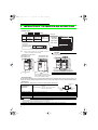
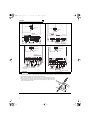
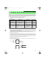
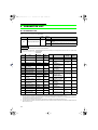
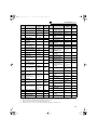
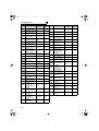
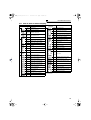
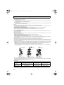
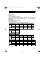
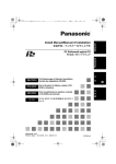
F700_kaigaidoukon_NA.book 1 ページ 2008年8月29日 金曜日 午後2時53分 INVERTER INSTALLATION GUIDELINE FR-F720-00046 to 04750-NA FR-F740-00023 to 12120-NA Thank you for choosing this Mitsubishi Inverter. Please read through this Installation Guideline and a CD-ROM enclosed to operate this inverter correctly. Do not use this product until you have a full knowledge of the equipment, safety information and instructions. Please forward this Installation Guideline and the CD-ROM to the end user. 1 CONTENTS INSTALLATION OF THE INVERTER AND INSTRUCTIONS................. 1 2 OUTLINE DRAWING............................................................................... 2 3 WIRING.................................................................................................... 4 4 PRECAUTIONS FOR USE OF THE INVERTER................................... 11 5 FAILSAFE OF THE SYSTEM WHICH USES THE INVERTER ............ 12 6 PARAMETER LIST................................................................................ 13 7 TROUBLESHOOTING........................................................................... 19 700 F700_kaigaidoukon_NA.book 2 ページ 2008年8月29日 金曜日 午後2時53分 F700_kaigaidoukon_NA.book 1 ページ 2008年8月29日 金曜日 午後2時53分 This section is specifically about safety matters Do not attempt to install, operate, maintain or inspect the inverter until you have read through this Installation Guideline and appended documents carefully and can use the equipment correctly. Do not use the inverter until you have a full knowledge of the equipment, safety information and instructions. In this Installation Guideline, the safety instruction levels are classified into "WARNING" and "CAUTION". Assumes that incorrect handling may cause hazardous conditions, resulting in death or severe injury. Assumes that incorrect handling may cause hazardous conditions, resulting in medium or slight injury, or may cause physical damage only. WARNING CAUTION CAUTION level may lead to a serious consequence Note that even the according to conditions. Please follow strictly the instructions of both levels because they are important to personnel safety. 1. Electric Shock Prevention WARNING • While power is on or when the inverter is running, do not open the front cover. Otherwise you may get an electric shock. • Do not run the inverter with the front cover removed. Otherwise, you may access the exposed high-voltage terminals or the charging part of the circuitry and get an electric shock. • Even if power is off, do not remove the front cover except for wiring or periodic inspection.You may access the charged inverter circuits and get an electric shock. • Before starting wiring or inspection, check to make sure that the operation panel indicator is off, wait for at least 10 minutes after the power supply has been switched off, and check that there are no residual voltage using a tester or the like. The capacitor is charged with high voltage for some time after power off and it is dangerous. • This inverter must be grounded. Grounding must conform to the requirements of national and local safety regulations and electrical codes. (NEC section 250, IEC 536 class 1 and other applicable standards) Use an neutral-point earthed (grounded) power supply for 400V class inverter in compliance with EN standard. • Any person who is involved in the wiring or inspection of this equipment should be fully competent to do the work. • Always install the inverter before wiring. Otherwise, you may get an electric shock or be injured. • Perform setting dial and key operations with dry hands to prevent an electric shock. Otherwise you may get an electric shock. • Do not subject the cables to scratches, excessive stress, heavy loads or pinching. Otherwise you may get an electric shock. • Do not replace the cooling fan while power is on. It is dangerous to replace the cooling fan while power is on. • Do not touch the printed circuit board with wet hands. You may get an electric shock. • When measuring the main circuit capacitor capacity, the DC voltage is applied to the motor for 1s at powering off. Never touch the motor terminal, etc. right after powering off to prevent an electric shock. 2. Fire Prevention CAUTION • Install the inverter on a nonflammable wall without holes (so that nobody can touch the inverter heatsink on the rear side, etc.). Mounting it to or near flammable material can cause a fire. • If the inverter has become faulty, switch off the inverter power. A continuous flow of large current could cause a fire. • Do not connect the resistor directly to the DC terminals P/+ and N/-. This could cause a fire. 3. Injury Prevention CAUTION • Apply only the voltage specified in the instruction manual to each terminal. Otherwise, burst, damage, etc. may occur. • Ensure that the cables are connected to the correct terminals. Otherwise, burst, damage, etc. may occur. • Always make sure that polarity is correct to prevent damage, etc. Otherwise, burst, damage, etc. may occur. • While power is on or for some time after power-off, do not touch the inverter as it is hot and you may get burnt. 4. Additional Instructions Also note the following points to prevent an accidental failure, injury, electric shock, etc. (1) Transportation and installation CAUTION Environment • When carrying products, use correct lifting gear to prevent injury. • Do not stack the inverter boxes higher than the number recommended. • Ensure that installation position and material can withstand the weight of the inverter. Install according to the information in the instruction manual. • Do not install or operate the inverter if it is damaged or has parts missing. This can result in breakdowns. • When carrying the inverter, do not hold it by the front cover or setting dial; it may fall off or fail. • Do not stand or rest heavy objects on the product. • Check the inverter mounting orientation is correct. • Prevent other conductive bodies such as screws and metal fragments or other flammable substance such as oil from entering the inverter. • As the inverter is a precision instrument, do not drop or subject it to impact. • Use the inverter under the following environmental conditions. Otherwise, the inverter may be damaged. Surrounding LD air SLD temperature (initial setting) Ambient humidity Storage temperature Atmosphere Altitude, vibration CAUTION (2) Wiring • Do not install a power factor correction capacitor or surge suppressor on the inverter output side. These devices on the inverter output side may be overheated or burn out. • The connection orientation of the output cables U, V, W to the motor will affect the direction of rotation of the motor. (3) Test operation and adjustment CAUTION • Before starting operation, confirm and adjust the parameters. A failure to do so may cause some machines to make unexpected motions. WARNING (4) Operation • When you have chosen the retry function, stay away from the equipment as it will restart suddenly after an alarm stop. • Since pressing • • • • key may not stop output depending on the function setting status, provide a circuit and switch separately to make an emergency stop (power off, mechanical brake operation for emergency stop, etc). Make sure that the start signal is off before resetting the inverter alarm. A failure to do so may restart the motor suddenly. The load used should be a three-phase induction motor only. Connection of any other electrical equipment to the inverter output may damage the inverter as well as equipment. Do not modify the equipment. Do not perform parts removal which is not instructed in this manual. Doing so may lead to fault or damage of the inverter. CAUTION • The electronic thermal relay function does not guarantee protection of the motor from overheating. It is recommended to install both an external thermal and PTC thermistor for overheat protection. • Do not use a magnetic contactor on the inverter input for frequent starting/ stopping of the inverter. • Use a noise filter to reduce the effect of electromagnetic interference. Otherwise nearby electronic equipment may be affected. • Take measures to suppress harmonics. Otherwise power supply harmonics from the inverter may heat/damage the power factor correction capacitor and generator. • When a 400V class motor is inverter-driven, please use an insulationenhanced motor or measures taken to suppress surge voltages. Surge voltages attributable to the wiring constants may occur at the motor terminals, deteriorating the insulation of the motor. • When parameter clear or all clear is performed, reset the required parameters before starting operations. Each parameter returns to the initial value. • The inverter can be easily set for high-speed operation. Before changing its setting, fully examine the performances of the motor and machine. • In addition to the inverter's holding function, install a holding device to ensure safety. • Before running an inverter which had been stored for a long period, always perform inspection and test operation. • For prevention of damage due to static electricity, touch nearby metal before touching this product to eliminate static electricity from your body. (5) Emergency stop CAUTION • Provide a safety backup such as an emergency brake which will prevent the machine and equipment from hazardous conditions if the inverter fails. • When the breaker on the inverter primary side trips, check for the wiring fault (short circuit), damage to internal parts of the inverter, etc. Identify the cause of the trip, then remove the cause and power on the breaker. • When the protective function is activated, take the corresponding corrective action, then reset the inverter, and resume operation. (6) Maintenance, inspection and parts replacement CAUTION • Do not carry out a megger (insulation resistance) test on the control circuit of the inverter. It will cause a failure. (7) Disposing of the inverter • Treat as industrial waste. CAUTION General instructions Many of the diagrams and drawings in instruction manuals show the inverter without a cover, or partially open. Never run the inverter in this status. Always replace the cover and follow instruction manuals when operating the inverter. -10°C to +50°C(14°F to 122°F)(non-freezing) -10°C to +40°C (14°F to 104°F)(non-freezing) 90% RH or less (non-condensing) -20°C to +65°C *1 (-4°F to 149°F) Indoors (free from corrosive gas, flammable gas, oil mist, dust and dirt) Maximum 1000m (3280.80feet) above sea level for standard operation. After that derate by 3% for every extra 500m (1640.40feet) up to 2500m (8202feet) (91%) 5.9m/s2 or less *2 *1 Temperature applicable for a short time, e.g. in transit. *2 2.9m/s2 or less for the FR-F740-04320 or more. A-1 F700_kaigaidoukon_NA.book 1 ページ 2008年8月29日 金曜日 午後2時53分 INSTALLATION OF THE INVERTER AND INSTRUCTIONS 1 INSTALLATION OF THE INVERTER AND INSTRUCTIONS • Inverter Type FR - F740 - 00126 - NA Symbol F720 F740 Voltage Class Three-phase 200V class 200V class 00046 to 04750 Symbol Type number Three-phase 400V class 400V class 00023 to 12120 Rating plate Rating plate Displays the rated current. FR-F740-00126-NA Inverter type Input rating Output rating LD (50 C) XXA SLD (40 C) XXA Serial number Capacity plate Capacity plate FR-F740-00126-NA Overload Current Rating Ambient Temperature Inverter type Serial number LD SLD 120% 60s, 150% 3s 110% 60s, 120% 3s 50 C(122 F) 40 C(104 F) • Installation of the inverter Note - Some inverter models may be installed outside an enclosure. See Appendix 2 for details. Installation on the enclosure FR-F720-01250 or less FR-F740-00620 or less CAUTION When encasing multiple inverters, install them in parallel as a cooling measure. FR-F720-01540 or more FR-F740-00770 or more 10cm(3.94inches) or more *2 10cm(3.94inches) or more *2 5cm(1.97inch es) or more *1 *1 1cm or more for FR-F720-00167 (FR-F740-00083) or less 10cm or more for FR-F720-03160 (FR-F740-01800) or more *2 20cm or more for FR-F720-03160 (FR-F740-01800) or more Fix six positions for the FR-F74004320 to 08660 and fix eight positions for the FR-F740-09620 to 12120. • General Precaution The bus capacitor discharge time is 10 minutes. Before starting wiring or inspection, switch power off, wait for more than 10 minutes, and check for residual voltage between terminal P/+ and N/- with a meter etc., to avoid a hazard of electrical shock. • Environment Before installation, check that the environment meets following specifications. Surrounding Air Temperature LD: -10°C to + 50°C (14°F to 122°F) Maximum (nonfreezing) SLD (initial setting): -10°C to + 40°C (14°F to 104°F) Maximum (non-freezing) Measurement position 5cm (1.97inches) Inverter Measurement position Ambient humidity Storage temperature Ambience Altitude, vibration 90%RH or less (non-condensing) -20°C to + 65°C (-4°F to 149°F) Indoors (No corrosive and flammable gases, oil mist, dust and dirt.) Below 1000m, 5.9m/s2 or less (2.9m/s2 or less for the FR-F740-04320 or more) CAUTION • • • • 1 Install the inverter on a non-combustible wall surface such as metal or concrete. Mount the inverter on a strong surface securely and vertically with bolts. Provide sufficient clearance distances away from other devices. WARNING: HEAT SINK SURFACE MAY BE HOT. TO REDUCE RISK OF BURN - DO NOT TOUCH. 5cm (1.97inches) 5cm (1.97inches) F700_kaigaidoukon_NA.book 2 ページ 2008年8月29日 金曜日 午後2時53分 OUTLINE DRAWING 2 OUTLINE DRAWING FR-F740-09620 to 12120-NA H1 H H1 H FR-F740-04320 to 08660-NA W1 W W1 W1 H1 H FR-F720-00046 to 04750-NA FR-F740-00023 to 03610-NA W1 W W1 W W1 D (Unit:mm(inches)) • 200V class Inverter Type FR-F720-00046-NA FR-F720-00077-NA FR-F720-00105-NA FR-F720-00167-NA FR-F720-00250-NA FR-F720-00340-NA FR-F720-00490-NA FR-F720-00630-NA FR-F720-00770-NA FR-F720-00930-NA FR-F720-01250-NA FR-F720-01540-NA FR-F720-01870-NA FR-F720-02330-NA FR-F720-03160-NA FR-F720-03800-NA FR-F720-04750-NA W W1 110 (4.33) 95 (3.74) 150 (5.91) 125 (4.92) 220 (8.66) 195 (7.68) 250 (9.84) 230 (9.06) 325 (12.8) 270 (10.63) 435 (17.13) 380 (14.96) 465 (18.31) 400 (15.75) H H1 D 110 (4.33) 125 (4.92) 260 (10.24) 245 (9.65) 140 (5.51) 170 (6.69) 300 (11.81) 285 (11.22) 400 (15.75) 380 (14.96) 550 (21.65) 740 (29.13) 190 (7.48) 530 (20.87) 195 (7.68) 525 (20.67) 250 (9.84) 715 (28.15) 360 (14.17) 2 F700_kaigaidoukon_NA.book 3 ページ 2008年8月29日 金曜日 午後2時53分 OUTLINE DRAWING • 400V class Inverter Type FR-F740-00023-NA FR-F740-00038-NA FR-F740-00052-NA FR-F740-00083-NA FR-F740-00126-NA FR-F740-00170-NA FR-F740-00250-NA FR-F740-00310-NA FR-F740-00380-NA FR-F740-00470-NA FR-F740-00620-NA FR-F740-00770-NA FR-F740-00930-NA FR-F740-01160-NA FR-F740-01800-NA FR-F740-02160-NA FR-F740-02600-NA FR-F740-03250-NA FR-F740-03610-NA FR-F740-04320-NA FR-F740-04810-NA FR-F740-05470-NA FR-F740-06100-NA FR-F740-06830-NA FR-F740-07700-NA FR-F740-08660-NA FR-F740-09620-NA FR-F740-10940-NA FR-F740-12120-NA 3 W W1 150 (5.91) 125 (4.92) H H1 260 (10.24) 245 (9.65) D 140 (5.51) 170 (6.69) 220 (8.66) 195 (7.68) 300 (11.81) 285 (11.22) 190 (7.48) 250 (9.84) 230 (9.06) 400 (15.75) 380 (14.96) 190 (7.48) 325 (12.8) 270 (10.63) 550 (21.65) 530 (20.87) 195 (7.68) 435 (17.13) 380 (14.96) 550 (21.65) 525 (20.67) 250 (9.84) 620 (24.41) 595 (23.43) 300 (11.81) 465 (18.31) 400 (15.75) 740 (29.13) 715 (28.15) 360 (14.17) 1010 (39.76) 984 (38.77) 380 (14.96) 498 (19.6) 200 (7.87) 680 (26.77) 300 (11.81) 790 (31.1) 315 (12.4) 1330 (52.36) 1300 (51.18) 995 (39.17) 300 (11.81) 1580 (62.2) 1550 (61.02) 440 (17.32) F700_kaigaidoukon_NA.book 4 ページ 2008年8月29日 金曜日 午後2時53分 3 WIRING Sink logic Main circuit terminal *1. DC reactor (FR-HEL) Control circuit terminal Ground Jumper P1 MC MCCB *2. To supply power to the control circuit separately, remove the jumper across R1/L11 and S1/L21. *2 Jumper P/+ PX*7 N/- CN8*6 U V W ON EMC filter ON/OFF OFF connector *8 R/L1 S/L2 T/L3 Three-phase AC power supply Jumper Resistor unit *6. A CN8 (for MT-BU5) connector is (Option) provided for the FR-F720-03160 Brake unit (FR-F740-01800) or more. (Option) *1 Be sure to connect the DC reactor supplied with the FR-F720-03160 (FR-F740-01800) or more. When a DC reactor is connected to the 02330 (FR-F740-01160) or less, remove the jumper across P1-P/+. R1/L11 S1/L21 PR*7 Main circuit Ground B1 STR A1 B2 Relay output 2 A2 Jog mode Second function selection JOG RUN RT SU MRS IPF Output stop RES *3 Reset OL AU 24VDC power supply (Common for external power supply transistor) PC CS PTC SD Frequency setting signal (Analog) 3 2 1 Auxiliary (+) input (-) Terminal 4 input (+) (-) (Current input) Connector Open collector output Running Terminal functions vary with the output Up to frequency terminal assignment (Pr. 190 to Pr. 194) Instantaneous Refer to the power failure Instruction Manual chapter4. Overload FU Frequency detection SINK AU SOURCE Terminal 4 input selection (Current input selection) Selection of automatic restart after instantaneous power failure Contact input common *5. It is recommended to use 2W1kΩ when the frequency setting signal is changed frequently. Refer to the Instruction Manual chapter4. RL Low speed (Refer to the Instruction Manual chapter4.) Relay output Terminal functions vary with the output Relay output 1 terminal assignment (Fault output) (Pr. 195, Pr. 196) C2 RM Middle speed *4. Terminal input specifications can be changed by analog input specifications switchover (Pr. 73, Pr. 267). Set the voltage/current input switch in the OFF position to select voltage input (0 to 5V/0 to 10V) and ON to select current input (0 to 20mA). Ground *8. The 200V class 00046 and 00077 are not provided with the ON/OFF connector EMC filter. STOP RH High speed Frequency setting potentiometer 1/2W1kΩ *5 IM C1 STF Start self-holding selection *3. AU terminal can be used as PTC input terminal. Motor Control circuit Control input signals (No voltage input allowed) Forward Terminal functions vary rotation with the input terminal start assignment Reverse (Pr. 178 to Pr. 189) rotation (Refer to the Instruction start Manual chapter4.) Multi-speed selection *7. Do not use PR and PX terminals. Please do not remove the jumper connected to terminal PR and PX. *4 Voltage/current input switch 4 2 ON 10(+5V) OFF 0 to 5VDC Initial value 2 0 to 10VDC selected *4 0 to 20mADC 5 (Analog common) SE PU connector 10E(+10V) Initial 0 to ±10VDC value 1 0 to ±5VDC selected *4 Initial 4 to 20mADC value 4 0 to 5VDC selected *4 0 to 10VDC CA AM 5 (+) (-) Analog current output (0 to 20mADC) Analog signal output (0 to 10VDC) RS-485 terminals TXD+ TXD- Data transmission RXD+ SG Option connector 1 (+) (-) RXD- for plug-in option connection Open collector output common Sink/source common Terminating resistor VCC Data reception GND 5V (Permissible load current 100mA) CAUTION • To prevent a malfunction due to noise, keep the signal cables more than 10cm away from the power cables. Also separate the main circuit wire of the input side and the output side. • After wiring, wire offcuts must not be left in the inverter. Wire offcuts can cause an alarm, failure or malfunction. Always keep the inverter clean. When drilling mounting holes in a control box etc., take care not to allow chips and other foreign matter to enter the inverter. • Set the voltage/current input switch correctly. Different setting may cause a fault, failure or malfunction. 4 F700_kaigaidoukon_NA.book 5 ページ 2008年8月29日 金曜日 午後2時53分 WIRING 3.1 Main circuit terminal (1) Terminal layout and wiring 200V class FR-F720-00046, 0007-NA FR-F720-00105 to 00250-NA Jumper Jumper Jumper Screw size (M4) Screw size (M4) R/L1 S/L2 T/L3 PR Jumper R1/L11 S1/L21 N/- IM Power supply Motor P/+ N/- R1/L11 S1/L21 PX P/+ R/L1 S/L2 T/L3 Screw size (M4) Charge lamp As this is an inside cover fixing screw, do not remove it. FR-F720-00340, 00490NA PX Screw size (M4) IM Power supply PR Charge lamp Motor FR-F720-00630-NA R1/L11 S1/L21 Charge lamp Screw size (M4) Jumper Charge lamp * * Jumper * N/- P/+ PR Jumper Jumper R1/L11 S1/L21 P/+ Screw size (M5) Screw size (M5) PX * R/L1 S/L2 T/L3 R/L1 S/L2 T/L3 IM PR IM Power supply Motor Screw size (M5) * Screw size of terminal R1/L11, S1/L21, PR and PX is M4. N/- Motor Power supply Screw size (M5) FR-F720-00770 to 01250-NA FR-F720-01540 to 02330-NA R1/L11 S1/L21 Screw size (M4) R1/L11 S1/L21 Screw size (M4) Charge lamp Screw size (00770:M6, 00930/01250:M8) Jumper N/- R/L1 S/L2 T/L3 IM Power supply Charge lamp PR Jumper P/+ Screw size (01540:M8, 01870/02330:M10) Jumper Motor Screw size (M6) R/L1 S/L2 T/L3 Power supply 5 N/- P/+ Jumper Screw size (01540:M6, 01870/02330:M8) IM Motor F700_kaigaidoukon_NA.book 6 ページ 2008年8月29日 金曜日 午後2時53分 WIRING FR-F720-03160 to 04750-NA R1/L11 S1/L21 Screw size (M4) Charge lamp Jumper Screw size (M12) R/L1 S/L2 T/L3 N/- P/+ P/+ Screw size (M10) P/+ Power supply Screw size (M12) (for option) IM Motor DC reactor 400V class FR-F740-00023, 00038, 00052, 00083, 00126-NA FR-F740-00170, 00250-NA Jumper Screw size (M4) Jumper R/L1 S/L2 T/L3 P/+ N/- Charge lamp PX R1/L11 S1/L21 IM Power supply PR Screw size (M4) N/- Jumper P/+ PR Jumper R1/L11 S1/L21 Charge lamp Screw size (M4) Motor PX R/L1 S/L2 T/L3 IM Motor Power supply Screw size (M4) FR-F740-00310, 00380-NA FR-F740-00470, 00620-NA R1/L11 S1/L21 Screw size (M4) R1/L11 S1/L21 Screw size (M4) Charge lamp Jumper Charge lamp Screw size (M6) Jumper PR Jumper P/+ Screw size (M5) N/- R/L1 S/L2 T/L3 R/L1 S/L2 T/L3 N/- IM PR Power supply P/+ Jumper Motor IM Motor Power supply Screw size (M5) Screw size (M6) 6 F700_kaigaidoukon_NA.book 7 ページ 2008年8月29日 金曜日 午後2時53分 WIRING FR-F740-00770 to 01160-NA FR-F740-01800 to 02600-NA R1/L11 S1/L21 Screw size(M4) Charge lamp R1/L11 S1/L21 Screw size (M4) Jumper Charge lamp Jumper Screw size (00770: M6 00930/01160: M8) Screw size Screw size (01800: M8, 02160/02600: M10) Screw size (M10) (01800: M8, 02160/02600: M10) R/L1 S/L2 T/L3 N/- R/L1 S/L2 T/L3 Power supply N/- P/+ Jumper P/+ P/+ Power supply IM Screw size (00770: M6 00930/01160: M8) Motor FR-F740-03250 to 04810-NA IM Motor DC reactor Screw size (01800: M8, 02160/02600: M10) FR-F740-05470 to 12120-NA R1/L11 S1/L21 Screw size (M4) R1/L11 S1/L21 Screw size (M4) Charge lamp Charge lamp Jumper Jumper Screw size (03250/03610: M10 04320/04810: M12) R/L1 S/L2 T/L3 N/- P/+ Screw size (M12) P/+ R/L1 S/L2 T/L3 N/- P/+ Screw size (M10) P/+ Power supply Screw size (M12) (for option) IM P/+ Motor DC reactor IM Motor Power supply DC reactor Screw size (M10) CAUTION · The power supply cables must be connected to R/L1, S/L2, T/L3. (Phase sequence needs not to be matched.) Never connect the power cable to the U, V, W of the inverter. Doing so will damage the inverter. · Connect the motor to U, V, W. At this time, turning on the forward rotation switch (signal) rotates the motor in the counterclockwise direction when viewed from the motor shaft. · When wiring the inverter main circuit conductor of the FR-F740-05470 or more, tighten a nut from the right side of the conductor. When wiring two wires, place wires on both sides of the conductor. (Refer to the drawing below.) For wiring, use bolts (nuts) provided with the inverter. 7 F700_kaigaidoukon_NA.book 8 ページ 2008年8月29日 金曜日 午後2時53分 WIRING (2) Cable size Select the recommended cable size to ensure that a voltage drop will be 2% max. If the wiring distance is long between the inverter and motor, a main circuit cable voltage drop will cause the motor torque to decrease especially at the output of a low frequency. The following table indicates a selection example for the wiring length of 20m (65.62feet). 200V class (when input power supply is 220V) Applicable Inverter Type Crimping Terminal Tightening Terminal Screw Torque R/L1, Size *4 N·m S/L2, U, V, W T/L3 FR-F720-00046 to M4 00105-NA FR-F720-00167-NA M4 FR-F720-00250-NA M4 FR-F720-00340-NA M5 FR-F720-00490-NA M5 FR-F720-00630-NA M5 FR-F720-00770-NA M6 FR-F720-00930-NA M8(M6) FR-F720-01250-NA M8(M6) FR-F720-01540-NA M8(M6) FR-F720-01870-NA M10(M8) FR-F720-02330-NA M10(M8) FR-F720-03160-NA M12(M10) FR-F720-03800-NA M12(M10) FR-F720-04750-NA M12(M10) *1 *2 *3 *4 *5 1.5 2-4 1.5 1.5 2.5 2.5 2.5 4.4 7.8 7.8 7.8 14.7 14.7 24.5 24.5 24.5 5.5-4 5.5-4 14-5 14-5 22-5 38-6 38-8 60-8 80-8 100-10 100-10 150-12 150-12 100-12 2-4 Cable Sizes HIV, etc. (mm2) *1 R/L1, S/L2, T/L3 2 AWG/MCM *2 Ground R/L1, S/L2, U, V, W T/L3 cable 2 5.5-4 3.5 3.5 5.5-4 5.5 5.5 8-5 14 8 14-5 14 14 22-5 22 22 38-6 38 38 38-8 38 38 60-8 60 60 80-8 80 80 100-10 100 100 100-10 100 100 150-12 125 125 150-12 150 150 100-12 2×100 2×100 PVC, etc. (mm2) *3 U, V, W R/L1, S/L2, T/L3 U, V, W Ground cable 2 14 14 2.5 2.5 2.5 3.5 5.5 14 14 14 22 22 38 38 60 60 38 38 38 12 10 6 6 4 2 2 1/0 3/0 4/0 4/0 250 2×4/0 2×4/0 12 10 8 6 6 (*5) 2 2 1/0 3/0 4/0 4/0 250 2×4/0 2×4/0 4 6 16 16 25 50 50 50 70 95 95 4 6 10 16 25 50 50 50 70 95 95 4 6 16 16 16 25 25 25 35 50 50 The recommended cable size is that of the cable (e.g. HIV cable (600V class 2 vinyl-insulated cable)) with continuous maximum permissible temperature of 75°C (167°F). Assumes that the surrounding air temperature is 50°C (122°F) or less and the wiring distance is 20m (65.62feet) or less. The recommended cable size is that of the cable (THHW cable) with continuous maximum permissible temperature of 75°C (167°F). Assumes that the surrounding air temperature is 40°C (104°F) or less and the wiring distance is 20m (65.62feet) or less. (Selection example for use mainly in the United States.) For the FR-F720-00930 or less, the recommended cable size is that of the cable (PVC cable) with continuous maximum permissible temperature of 70°C (158°F). Assumes that the surrounding air temperature is 40°C (104°F) or less and the wiring distance is 20m(65.62feet) or less. For the FR-F720-01250 or more, the recommended cable size is that of the cable (XLPE cable) with continuous maximum permissible temperature of 90°C (194°F). Assumes that the surrounding air temperature is 40°C (104°F) or less and wiring is performed in an enclosure. (Selection example for use mainly in Europe.) The terminal screw size indicates the terminal size for R/L1, S/L2, T/L3, U, V, W, and a screw for grounding. A screw for earthing (grounding) of the FR-F720-00930 or more is indicated in ( ). When connecting the option unit to P/+, P1, N/-, use THHN cables for the option and terminals R/L1, S/L2, T/L3, U, V, W. 8 F700_kaigaidoukon_NA.book 9 ページ 2008年8月29日 金曜日 午後2時53分 WIRING 400V class (when input power supply is 440V based on the rated current for 110% overload for 1 minute) Applicable Inverter Type FR-F740-00023 to 00083-NA FR-F740-00126-NA FR-F740-00170-NA FR-F740-00250-NA FR-F740-00310-NA FR-F740-00380-NA FR-F740-00470-NA FR-F740-00620-NA FR-F740-00770-NA FR-F740-00930-NA FR-F740-01160-NA FR-F740-01800-NA FR-F740-02160-NA FR-F740-02600-NA FR-F740-03250-NA FR-F740-03610-NA FR-F740-04320-NA FR-F740-04810-NA FR-F740-05470-NA FR-F740-06100-NA FR-F740-06830-NA FR-F740-07700-NA FR-F740-08660-NA FR-F740-09620-NA FR-F740-10940-NA FR-F740-12120-NA *1 *2 *3 *4 Terminal Tightening Screw Size Torque N·m *4 Crimping (Compression) Terminal R/L1, U, V, S/L2, W T/L3 Cable Sizes HIV, etc. (mm2) *1 R/L1, S/L2, T/L3 U, V, W Ground cable AWG/MCM *2 R/L1, S/L2, T/L3 PVC, etc. (mm2) *3 U, V, W R/L1, S/L2, T/L3 U, V, W Ground cable M4 1.5 2-4 2-4 2 2 2 14 14 2.5 2.5 2.5 M4 M4 M4 M5 M5 M6 M6 M6 M8 M8 M8 M10 M10 M10 M10 M12(M10) M12(M10) M12(M10) M12(M10) M12(M10) M12(M10) M12(M10) M12(M10) M12(M10) M12(M10) 1.5 1.5 1.5 2.5 2.5 4.4 4.4 4.4 7.8 7.8 7.8 14.7 14.7 14.7 14.7 24.5 24.5 24.5 24.5 24.5 24.5 24.5 24.5 24.5 24.5 2-4 5.5-4 5.5-4 8-5 14-5 14-6 22-6 22-6 38-8 60-8 60-8 100-10 100-10 150-10 150-10 100-12 100-12 150-12 150-12 200-12 C2-200 C2-250 C2-250 C2-200 C2-200 2-4 5.5-4 5.5-4 8-5 8-5 14-6 22-6 22-6 38-8 60-8 60-8 100-10 150-10 150-10 150-10 100-12 100-12 150-12 150-12 200-12 C2-200 C2-250 C2-250 C2-200 C2-200 2 3.5 5.5 8 14 14 22 22 38 60 60 80 100 125 150 2×100 2×100 2×125 2×150 2×200 2×200 2×250 2×250 3×200 3×200 2 3.5 5.5 8 8 14 22 22 38 60 60 80 100 125 150 2×100 2×100 2×125 2×150 2×200 2×200 2×250 2×250 3×200 3×200 3.5 3.5 8 8 14 14 14 14 22 22 38 38 38 38 38 38 38 38 38 60 60 60 100 100 100 12 12 10 8 6 6 4 4 1 1/0 1/0 3/0 4/0 250 300 2×4/0 2×4/0 2×250 2×300 2×350 2×400 2×500 2×500 3×350 3×400 14 12 10 8 8 6 4 4 2 1/0 1/0 3/0 4/0 250 300 2×4/0 2×4/0 2×250 2×300 2×350 2×400 2×500 2×500 3×350 3×400 2.5 4 6 10 16 16 25 25 50 50 50 70 95 120 150 2×95 2×95 2×120 2×150 2×185 2×185 2×240 2×240 3×185 3×185 2.5 4 6 10 10 16 25 25 50 50 50 70 95 120 150 2×95 2×95 2×120 2×150 2×185 2×185 2×240 2×240 3×185 3×185 4 4 10 10 16 16 16 16 25 25 25 35 50 70 95 95 95 120 150 2×95 2×95 2×120 2×120 2×150 2×150 For the FR-F740-01160 or less, the recommended cable size is that of the cable (e.g. HIV cable (600V class 2 vinyl-insulated cable)) with continuous maximum permissible temperature of 75°C (167°F). Assumes that the ambient temperature is 50°C (122°F) or less and the wiring distance is 20m (65.62feet) or less. For the FR-F740-01800 or more, the recommended cable size is that of the cable (e.g. LMFC (heat resistant flexible cross-linked polyethylene insulated cable)) with continuous maximum permissible temperature of 90°C (194°F). Assumes that the surrounding air temperature is 50°C (122°F) or less and wiring is performed in an enclosure. For the FR-F740-00930 or less, the recommended cable size is that of the cable (THHW cable) with continuous maximum permissible temperature of 75°C (167°F). Assumes that the surrounding air temperature is 40°C (104°F) or less and the wiring distance is 20m (65.62feet) or less. For the FR-F740-01160 or more, the recommended cable size is that of the cable (THHN cable) with continuous maximum permissible temperature of 90°C (194°F). Assumes that the surrounding air temperature is 40°C (104°F) or less and wiring is performed in an enclosure. (Selection example for use mainly in the United States.) For the FR-F740-00930 or less, the recommended cable size is that of the cable (PVC cable) with continuous maximum permissible temperature of 70°C (158°F). Assumes that the surrounding air temperature is 40°C (104°F) or less and the wiring distance is 20m (65.62feet) or less. For the FR-F740-01160 or more, the recommended cable size is that of the cable (XLPE cable) with continuous maximum permissible temperature of 90°C (194°F). Assumes that the surrounding air temperature is 40°C (104°F) or less and wiring is performed in an enclosure. (Selection example for use mainly in the Europe.) The terminal screw size indicates the terminal size for R/L1, S/L2, T/L3, U, V, W, and a screw for grounding. A screw for earthing (grounding) of the FR-F740-04320 or more is indicated in ( ). The line voltage drop can be calculated by the following formula: line voltage drop [V]= 3 × wire resistance[mΩ/m] × wiring distance[m] × current[A] 1000 Use a larger diameter cable when the wiring distance is long or when it is desired to decrease the voltage drop (torque reduction) in the low speed range. CAUTION · Tighten the terminal screw to the specified torque. A screw that has been tighten too loosely can cause a short circuit or malfunction. A screw that has been tighten too tightly can cause a short circuit or malfunction due to the unit breakage. · Use crimping terminals with insulation sleeve to wire the power supply and motor. 9 F700_kaigaidoukon_NA.book 10 ページ 2008年8月29日 金曜日 午後2時53分 WIRING (3) Total wiring length The overall wiring length for connection of a single motor or multiple motors should be within the value in the table below. Pr. 72 PWM frequency selection setting (carrier frequency) FR-F720-00046 FR-F740-00023 FR-F720-00077 FR-F740-00038 300m (984.25feet) 200m (656.19feet) 500m (1640.42feet) 300m (984.25feet) 2 (2kHz) or less 3 to 15 (3kHz to 14.5kHz) FR-F720-00105 or more FR-F740-00052 or more 500m (1640.42feet) 500m (1640.42feet) When driving a 400V class motor by the inverter, surge voltages attributable to the wiring constants may occur at the motor terminals, deteriorating the insulation of the motor. Take the following measures in this case. Take the following measures (1) or (2) in this case. (1) Use a "400V class inverter-driven insulation-enhanced motor" and set frequency in Pr. 72 PWM frequency selection according to wiring length. Wiring Length 50m (164.04feet) or less 50m (164.04feet) to 100m(328.08feet) exceeding 100m (328.08feet) 14.5kHz or less 9kHz or less 4kHz or less Pr. 72 PWM frequency selection setting (carrier frequency) (2) Connect the surge voltage suppression filter (FR-ASF-H) to the FR-F720-02330 (FR-F740-01160) or less and the sine wave filter (MT-BSL/BSC) to the FR-F720-03160 (FR-F740-01800) or more on the inverter output side. CAUTION · Especially for long-distance wiring, the inverter may be affected by a charging current caused by the stray capacitances of the wiring, leading to a malfunction of the overcurrent protective function or fast response current limit function or a malfunction or fault of the equipment connected on the inverter output side. If fast-response current limit function malfunctions, disable this function. (For Pr.156 Stall prevention operation selection, refer to the Instruction Manual.) · For details of Pr. 72 PWM frequency selection ,refer to the Instruction Manual. When using an optional sine wave filter (MT-BSL/BSC) for the FR-F720-03160 (FR-F740-01800) or more, set “25” in Pr.72 (2.5kHz). For explanation of surge voltage suppression filter (FR-ASF-H) and sine wave filter (MT-BSL/BSC), refer to the manual of each option. (4) Cable size of the control circuit power supply (terminal R1/L11, S1/L21) · Terminal screw size: M4 · Cable size: 0.75mm2 to 2mm2 · Tightening torque: 1.5N·m 3.2 Control circuit terminals (1) Terminal layout · Terminal Screw Size: M3.5 · Tightening torque: 1.2N·m A1 B1 C1 RL RM RH A2 RT B2 C2 10E 10 2 AU STOP MRS RES SD SE RUN SU IPF OL FU SD 5 4 CA AM SD STF STR JOG CS 1 PC (2) Instructions for wiring of the control circuit terminal 1) 2) 3) Terminals 5, PC and SE are common to the I/O signals and isolated from each other. Do not ground. Use shielded or twisted cables for connection to the control circuit terminals and run them away from the main and power circuits (including the 200V relay sequence circuit). Use two or more parallel micro-signal contacts or twin contacts to prevent a contact faults when using contact inputs since the control circuit input signals are micro-currents. Micro signal contacts 4) 5) 6) 7) Twin contacts Do not apply a voltage to the contact input terminals (e.g. STF) of the control circuit. Always apply a voltage to the fault output terminals (A, B, C) via a relay coil, lamp, etc. It is recommended to use the cables of 0.75mm2 gauge for connection to the control circuit terminals. If the cable gauge used is 1.25mm2 or more, the front cover may be lifted when there are many cables running or the cables are run improperly, resulting in an operation panel contact fault. The wiring length should be 30m (98.43feet) maximum. 10 F700_kaigaidoukon_NA.book 11 ページ 2008年8月29日 金曜日 午後2時53分 PRECAUTIONS FOR USE OF THE INVERTER 4 PRECAUTIONS FOR USE OF THE INVERTER The FR-F700 series is a highly reliable product, but incorrect peripheral circuit making or operation/handling method may shorten the product life or damage the product. Before starting operation, always recheck the following items. (1) (2) (3) (4) (5) (6) (7) (8) (9) (10) (11) (12) (13) (14) (15) (16) 11 Use crimping terminals with insulation sleeve to wire the power supply and motor. Application of power to the output terminals (U, V, W) of the inverter will damage the inverter. Never perform such wiring. After wiring, wire offcuts must not be left in the inverter. Wire offcuts can cause an alarm, failure or malfunction. Always keep the inverter clean. When drilling mounting holes in an enclosure etc., take care not to allow chips and other foreign matter to enter the inverter. Use cables of the size to make a voltage drop 2% maximum. If the wiring distance is long between the inverter and motor, a main circuit cable voltage drop will cause the motor torque to decrease especially at the output of a low frequency. Refer to page 8 for the recommended cable sizes. The overall wiring length should be 500m (1640.4 feet) maximum. Especially for long distance wiring, the fast response current limit function may decrease or the equipment connected to the secondary side may malfunction or become faulty under the influence of a charging current due to the stray capacity of the wiring. Therefore, note the overall wiring length. (Refer to page 10.) Electromagnetic wave interference The input/output (main circuit) of the inverter includes high frequency components, which may interfere with the communication devices (such as AM radios) used near the inverter. In this case, set the EMC filter valid to minimize interference. Do not install a power factor correction capacitor, surge suppressor or radio noise filter on the inverter output side. This will cause the inverter to trip or the capacitor, varistor, or arrester to be damaged. If any of the above devices is installed, immediately remove it. Before starting wiring or other work after the inverter is operated, wait for at least 10 minutes after the power supply has been switched off, and check that there are no residual voltage using a tester or the like. The capacitor is charged with high voltage for some time after power off and it is dangerous. A short circuit or ground fault on the inverter output side may damage the inverter modules. · Fully check the insulation resistance of the circuit prior to inverter operation since repeated short circuits caused by peripheral circuit inadequacy or a ground fault caused by wiring inadequacy or reduced motor insulation resistance may damage the inverter modules. · Fully check the to-ground insulation and phase to phase insulation of the inverter output side before power-on. Especially for an old motor or use in hostile atmosphere, securely check the motor insulation resistance etc. Do not use the inverter input side magnetic contactor to start/stop the inverter. Always use the start signal (ON/OFF of STF and STR signals) to start/stop the inverter. Do not apply a voltage higher than the permissible voltage to the inverter I/O signal circuits. Application of permissible voltage to the inverter I/O signal circuit and incorrect polarity may damage the I/O terminal. Especially check the wiring to prevent the speed setting potentiometer from being connected incorrectly to short terminals 10E-5. Provide electrical and mechanical interlocks for MC1 and MC2 MC1 which are used for bypass operation. Interlock When the wiring is incorrect and if there is a bypass operation Power R/L1 U IM circuit as shown right, the inverter will be damaged when the supply S/L2 V MC2 power supply is connected to the inverter U, V, W terminals, due T/L3 W to arcs generated at the time of switch-over or chattering caused Undesirable current Inverter by a sequence error. If the machine must not be restarted when power is restored after a power failure, provide a magnetic contactor in the inverter's input side and also make up a sequence which will not switch on the start signal. If the start signal (start switch) remains on after a power failure, the inverter will automatically restart as soon as the power is restored. Instructions for overload operation When performing operation of frequent start/stop of the inverter, increase/decrease in the temperature of the transistor element of the inverter may repeat due to a continuous flow of large current, shortening the life from thermal fatigue. Since thermal fatigue is related to the amount of current, the life can be increased by reducing bound current, starting current, etc. Decreasing current may increase the life. However, decreasing current will result in insufficient torque and the inverter may not start. Therefore, increase the inverter capacity to have enough allowance for current. Make sure that the specifications and rating match the system requirements. When the motor speed is unstable, due to change in the frequency setting signal caused by electromagnetic noises from the inverter, take the following measures when applying the motor speed by the analog signal. · Do not run the signal cables and power cables (inverter I/O cables) in parallel with each other and do not bundle them. · Run signal cables as far away as possible from power cables (inverter I/O cables). · Use shield cables as signal cables. · Install a ferrite core on the signal cable (Example: ZCAT3035-1330 TDK). F700_kaigaidoukon_NA.book 12 ページ 2008年8月29日 金曜日 午後2時53分 FAILSAFE OF THE SYSTEM WHICH USES THE INVERTER 5 FAILSAFE OF THE SYSTEM WHICH USES THE INVERTER When a fault occurs, the inverter trips to output a fault signal. However, a fault output signal may not be output at an inverter fault occurrence when the detection circuit or output circuit fails, etc. Although we assure best quality products, provide an interlock which uses inverter status output signals to prevent accidents such as damage to machine when the inverter fails for some reason and at the same time consider the system configuration where failsafe from outside the inverter, without using the inverter, is enabled even if the inverter fails. (1) Interlock method which uses the inverter status output signals By combining the inverter status output signals to provide an interlock as shown below, an inverter alarm can be detected. No Interlock Method Check Method Used Signals 1) Inverter protective function operation Operation check of an alarm contact Circuit error detection by negative logic Fault output signal (ALM signal) 2) Inverter running status Operation ready signal check Operation ready signal (RY signal) 3) Inverter running status Logic check of the start signal and running signal 4) Inverter running status Logic check of the start signal and output current Start signal (STF signal, STR signal) Running signal (RUN signal) Start signal (STF signal, STR signal) Output current detection signal (Y12 signal) Refer to Page Refer to the chapter 4 of the Instruction Manual. Refer to the chapter 4 of the Instruction Manual. Refer to the chapter 4 of the Instruction Manual. Refer to the chapter 4 of the Instruction Manual. (2) Backup method outside the inverter Even if the interlock is provided by the inverter status signal, enough failsafe is not ensured depending on the failure status of the inverter itself. For example, when the inverter CPU fails, even if the interlock is provided using the inverter fault signal, start signal and RUN signal, there is a case where a fault signal is not output and RUN signal is kept output even if an inverter fault occurs. Provide a speed detector to detect the motor speed and current detector to detect the motor current and consider the backup system such as checking up as below according to the level of importance of the system. 1) Start signal and actual operation check Check the motor running and motor current while the start signal is input to the inverter by comparing the start signal to the inverter and detected speed of the speed detector or detected current of the current detector. Note that the motor current runs as the motor is running for the period until the motor stops since the inverter starts decelerating even if the start signal turns off. For the logic check, configure a sequence considering the inverter deceleration time. In addition, it is recommended to check the three-phase current when using the current detector. 2) Command speed and actual operation check Check if there is no gap between the actual speed and commanded speed by comparing the inverter speed command and detected speed of the speed detector. Controller System failure Inverter Sensor (speed, temperature, air volume, etc.) To the alarm detection sensor 12 F700_kaigaidoukon_NA.book 13 ページ 2008年8月29日 金曜日 午後2時53分 PARAMETER LIST 6 PARAMETER LIST 6.1 Parameter list In the initial setting, only the simple mode parameters are displayed. Set Pr. 160 User group read selection as required. Parameter Initial Value Name Setting Range 9999 160 User group read selection 0 0 1 Remarks Only the simple mode parameters can be displayed. Simple mode and extended mode parameters can be displayed. Only the parameters registered in the user group can be displayed. REMARKS ⋅ The parameters marked are the simple mode parameters. ⋅ The parameters marked with in the table allow its setting to be changed during operation even if "0" (initial value) is set in Pr. 77 Parameter write selection. Parameters Name Setting Range 0 Torque boost 0 to 30% 1 Maximum frequency 0 to 120Hz Initial Value 6/4/3/2/ 1.5/1% *2 120/60Hz *1 Name 17 MRS input selection 18 High speed 120 to 400Hz maximum frequency 19 Base frequency voltage 2 3 Minimum frequency 0 to 120Hz 0Hz Base frequency 0 to 400Hz 60Hz 4 Multi-speed setting (high speed) Multi-speed setting (middle speed) Multi-speed setting (low speed) 0 to 400Hz 60Hz 0 to 400Hz 30Hz 21 10Hz 22 5 6 0 to 400Hz 7 8 Acceleration time 0 to 3600/360s 5s/15s *3 Deceleration time 0 to 3600/360s 10s/30s *3 9 Electronic thermal O/L relay 0 to 500/ 0 to 3600A *1 10 DC injection brake operation frequency 0 to 120Hz, 9999 3Hz 11 0 to 10s, 8888 0.5s 12 DC injection brake operation time DC injection brake operation voltage 0 to 30% 4/2/1% *4 13 Starting frequency 0 to 60Hz 0.5Hz 14 Load pattern selection 0, 1 15 Jog frequency 0 to 400Hz 5Hz 16 Jog acceleration/ deceleration time 0 to 3600/360s 0.5s *1 *2 *3 *4 13 Rated inverter current Setting Range Parameters 20 23 Acceleration/ deceleration reference frequency Acceleration/ deceleration time increments Stall prevention operation level Stall prevention operation level compensation factor at double speed Multi-speed setting 24 to 27 4 speed to 7 speed 28 29 30 1 Multi-speed input compensation selection Acceleration/ deceleration pattern selection Regenerative function selection 31 Frequency jump 1A 32 Frequency jump 1B 0, 2 Initial Value 0 120/60Hz *1 0 to 1000V, 8888, 9999 9999 1 to 400Hz 60Hz 0, 1 0 0 to 120%, 9999 110% 0 to 150%, 9999 9999 0 to 400Hz, 9999 9999 0, 1 0 0, 1, 2, 3 0 0, 2/0, 1, 2 *1 0 0 to 400Hz, 9999 0 to 400Hz, 9999 9999 9999 The setting depends on capacities. (FR-F720-02330 (FR-F740-01160) or less/FR-F720-03160 (FR-F740-01800) or more) The setting depends on capacities. (FR-F720-00046/00077 to 00167/00250, 00340/00490 to 01540/01870, FR-F740-00023/00038 to 00083/00126, 00170/00250 to 00770/00930, 01160/01800 or more) The setting depends on capacities. (FR-F720-00340 ( FR-F740-00170) or less/FR-F720-00490 (FR-F740-00250) or more) The setting depends on capacities. (FR-F720-00340 (FR-F740-00170) or less/FR-F720-00490 to 02330 (FR-F740-00250 to 01160)/FR-F720-03160 (FR-F740-01800) or more) F700_kaigaidoukon_NA.book 14 ページ 2008年8月29日 金曜日 午後2時53分 PARAMETER LIST Parameters Name 33 Frequency jump 2A 34 Frequency jump 2B 35 Frequency jump 3A 36 Frequency jump 3B 37 Speed display 41 Up-to-frequency sensitivity Output frequency detection Output frequency detection for reverse rotation Second acceleration/ deceleration time 42 43 44 Setting Range 0 to 400Hz, 9999 0 to 400Hz, 9999 0 to 400Hz, 9999 0 to 400Hz, 9999 Initial Value Parameters Name 9999 66 9999 68 Retry waiting time 0 to 10s 1s 69 0 0 0 70 Retry count display erase Special regenerative brake duty *3 0 to 10% 0% 0 to 100% 10% 71 Applied motor 0, 1, 2, 20 0 0 to 400Hz 6Hz 72 PWM frequency selection 0 to 15/ 0 to 6, 25 *1 2 73 Analog input selection 0 to 7, 10 to 17 1 74 Input filter time constant Reset selection/ disconnected PU detection/PU stop selection Fault code output selection Parameter write selection Reverse rotation prevention selection Operation mode selection 0 to 8 1 0 to 3, 14 to 17, 100 to 103, 114 to 117 *4 14 0, 1, 2 0 0, 1, 2 0 0, 1, 2 0 0, 1, 2, 3, 4, 6, 7 0 0, 1 to 9998 0 to 400Hz, 9999 0 to 3600/360s 9999 5s Second torque boost 0 to 30%, 9999 9999 47 Second V/F (base frequency) 0 to 400Hz, 9999 9999 0 to 120% 110% Second electronic thermal O/L relay 52 DU/PU main display data selection 54 CA terminal function selection *1 *2 *3 *4 77 78 79 0 to 400Hz 30Hz 80 9999 90 0 to 500A, 9999/ 0 to 3600A, 9999 *1 0, 5, 6, 8 to 14, 17, 20, 23 to 25, 50 to 57, 100 *2 1 to 3, 5, 6, 8 to 14, 17, 21, 24, 50, 52, 53 Frequency monitoring reference 0 to 400Hz 56 Current monitoring reference 0 to 500A/ 0 to 3600A *1 57 0, 0.1 to 5s, 9999/ Restart coasting time 0, 0.1 to 30s, 9999 *1 58 Restart cushion time 59 Remote function selection Energy saving control selection Retry selection 76 0Hz 55 65 75 0 to 400Hz, 9999 0 100 101 1 *2 60 0 9999 46 51 60Hz Number of retries at fault occurrence 9999 50 0 to 400Hz 67 0 to 3600/ 360s, 9999 49 Stall prevention operation reduction starting frequency 9999 Second deceleration time Second stall prevention operation current Second stall prevention operation frequency Second output frequency detection Initial Value 0, 1 to 10, 101 to 110 45 48 Setting Range 60Hz Rated inverter current 9999 102 103 104 105 106 107 0 to 60s 1s 0, 1, 2, 3 0 0, 4, 9 0 0 to 5 0 108 109 117 0.4 to 55kW, Motor 9999/ capacity(Simple magnetic flux vector 0 to 3600kW, control) 9999 *1 0 to 50Ω, 9999/ Motor constant (R1) 0 to 400mΩ, 9999 *1 0 to 400Hz, V/F1 (first frequency) 9999 V/F1 (first frequency 0 to 1000V voltage) 0 to 400Hz, V/F2 (second frequency) 9999 V/F2 (second 0 to 1000V frequency voltage) 0 to 400Hz, V/F3 (third frequency) 9999 V/F3 (third 0 to 1000V frequency voltage) 0 to 400Hz, V/F4 (fourth frequency) 9999 V/F4 (fourth 0 to 1000V frequency voltage) 0 to 400Hz, V/F5 (fifth frequency) 9999 V/F5 (fifth frequency 0 to 1000V voltage) PU communication 0 to 31 station 9999 9999 9999 0V 9999 0V 9999 0V 9999 0V 9999 0V 0 The setting depends on capacities. (FR-F720-02330 (FR-F740-01160) or less/FR-F720-03160 (FR-F740-01800) or more) Setting of "9" can be made for the FR-F720-03160 (FR-F740-01800) or more. Setting can be made for the FR-F720-03160 (FR-F740-01800) or more. Setting of "100 to 103", "114 to 117" can be made for the FR-F720-03160 (FR-F740-01800) or more. 14 F700_kaigaidoukon_NA.book 15 ページ 2008年8月29日 金曜日 午後2時53分 PARAMETER LIST Parameters 118 119 120 121 Name PU communication speed PU communication stop bit length. PU communication parity check Number of PU communication retries 122 PU communication check time interval 123 PU communication waiting time setting 124 PU communication CR/LF selection Terminal 2 frequency setting gain frequency Terminal 4 frequency setting gain frequency 125 126 127 PID control automatic switchover freqeuncy 128 PID action selection 129 PID proportional band 130 PID integral time 131 PID upper limit 132 PID lower limit 133 PID action set point 134 PID differential time 135 Electronic bypass sequence selection MC switchover interlock time Waiting time at a start Bypass selection at a fault Automatic switchover frequency from inverter to bypass operation Backlash acceleration stopping frequency Backlash acceleration stopping time Backlash deceleration stopping frequency Backlash deceleration stopping time 136 137 138 139 140 141 142 143 *1 15 Setting Range Initial Value 48, 96, 192, 384 192 0, 1, 10, 11 1 0, 1, 2 2 0 to 10, 9999 1 Parameters 144 Speed setting switchover 145 PU display language selection Stall prevention level at 0V input. Stall prevention level at 10V input. Output current detection level Output current detection signal delay time Zero current detection level Zero current detection time Voltage reduction selection during stall prevention operation RT signal reflection time selection 148 0, 0.1 to 999.8s, 9999 0 to 150ms, 9999 0, 1, 2 149 9999 150 9999 151 1 152 0 to 400Hz 60Hz 153 0 to 400Hz 60Hz 154 0 to 400Hz, 9999 10, 11, 20, 21, 50, 51, 60, 61 0.1 to 1000%, 9999 0.1 to 3600s, 9999 0 to 100%, 9999 0 to 100%, 9999 0 to 100%, 9999 0.01 to 10.00s, 9999 0, 1 9999 10 100% 0 to 7 1 0 to 120% 110% 0 to 120% 120% 0 to 120% 110% 0 to 10s 0s 0 to 150% 5% 0 to 1s 0.5s 0, 1 1 156 0 157 OL signal output timer 0 to 25s, 9999 0s AM terminal function selection 1 to 3, 5, 6, 8 to 14, 17, 21, 24, 50, 52, 53 *1 1 159 160 0 161 0 4 0 9999 1s 0, 2, 4, 6, 8, 10, 102, 104, 106, 108, 110 0 to 31, 100, 101 9999 0.5s Initial Value 0, 10 158 0 to 100s Setting Range Stall prevention operation selection 9999 0 to 100s 0, 1 155 1s 9999 Name 162 163 164 0 to 60Hz, 9999 9999 0 to 400Hz 1Hz 166 0 to 360s 0.5s 167 0 to 400Hz 1Hz 0 to 360s 0.5s 165 Setting of "9" can be made for the FR-F720-03160 (FR-F740-01800) or more. Automatic switchover frequency range from bypass to inverter operation User group read selection Frequency setting/ key lock operation selection Automatic restart after instantaneous power failure selection First cushion time for restart First cushion voltage for restart Stall prevention operation level for restart Output current detection signal retention time Output current detection operation selection 0 to 10Hz, 9999 9999 0, 1, 9999 0 0, 1, 10, 11 0 0, 1, 10, 11 0 0 to 20s 0s 0 to 100% 0% 0 to 120% 110% 0 to 10s, 9999 0.1s 0, 1 0 F700_kaigaidoukon_NA.book 16 ページ 2008年8月29日 金曜日 午後2時53分 PARAMETER LIST Parameters 168 169 Parameter for manufacturer setting. Do not set. 170 Cumulative power meter clear Operation hour meter clear User group registered display/ batch clear User group registration 171 172 173 174 User group clear 9999 0, 9999 9999 9999, (0 to 16) 0 0 to 999, 9999 9999 0 to 999, 9999 9999 0 to 8, 10 to 12, 14, 16, 24, 25, 60, 62, 64 to 67, 9999 0 to 8, 10 to 12, 14, 16, 24, 25, 61, 62, 64 to 67, 9999 STF terminal function selection 179 STR terminal function selection 180 RL terminal function selection RM terminal function selection RH terminal function selection RT terminal function selection 0 to 8, 10 to 14, 16, 24, 25, 62, 64 to 67, 9999 AU terminal function selection 0 to 8, 10 to 14, 16, 24, 25, 62 to 67, 9999 182 183 184 185 186 187 188 189 190 JOG terminal function selection CS terminal function selection MRS terminal function selection STOP terminal function selection RES terminal function selection RUN terminal function selection 191 SU terminal function selection 192 IPF terminal function selection 193 OL terminal function selection 194 FU terminal function selection Initial Value 0, 10, 9999 178 181 *1 Setting Range Name 60 195 ABC1 terminal function selection 196 ABC2 terminal function selection 232 to 239 Multi-speed setting (speeds 8 to 15) 240 61 0 241 242 1 2 243 3 244 4 6 Soft-PWM operation selection Analog input display unit switchover Terminal 1 added compensation amount (terminal 2) Terminal 1 added compensation amount (terminal 4) Cooling fan operation selection 245 Rated slip 246 Slip compensation time constant Constant-power range slip compensation selection 5 0 to 8, 10 to 14, 16, 24, 25, 62, 64 to 67, 9999 Name Parameters 247 24 Setting Range 0 to 5, 7, 8, 10 to 19, 25, 26, 45 to 47, 64, 70 to 78, 90, 91, 94 to 96, 98, 99,100 to 105, 107, 108, 110 to 116, 125, 126, 145 to 147, 164, 170, 190, 191, 194 to 196,198, 199, 9999 *1 0 to 400Hz, 9999 Initial Value 99 9999 9999 0, 1 1 0, 1 0 0 to 100% 100% 0 to 100% 75% 0, 1 1 0 to 50%, 9999 9999 0.01 to 10s 0.5s 0, 9999 9999 9999 250 Stop selection 0 to 100s, 1000 to 1100s, 8888, 9999 62 251 Output phase loss protection selection 0, 1 0 to 5, 7, 8, 10 to 19, 25, 26, 45 to 47, 64, 70 to 78, 90 to 96, 98, 99, 100 to 105, 107, 108, 110 to 116, 125, 126, 145 to 147, 164, 170, 190 to 196, 198, 199, 9999 0 252 253 Override bias 0 to 200% 50% Override gain 0 to 200% 150% 255 *1 4 Life alarm status display Inrush current limit circuit life display Control circuit capacitor life display Main circuit capacitor life display 25 1 256 2 257 3 258 (0 to 15) 1 0 (0 to 100%) 100% (0 to 100%) 100% (0 to 100%) 100% Setting of "7, 107" can be made for the FR-F720-03160 (FR-F740-01800) or more. 16 F700_kaigaidoukon_NA.book 17 ページ 2008年8月29日 金曜日 午後2時53分 PARAMETER LIST Parameters 259 260 261 262 263 Name Main circuit capacitor life measuring PWM frequency automatic switchover Power failure stop selection Subtracted frequency at deceleration start Subtraction starting frequency Setting Range Initial Value 0, 1 0 0, 1 1 0, 1, 2 0 to 20Hz 0 to 120Hz, 9999 0 3Hz 60Hz Power-failure deceleration time 1 0 to 3600/ 360s 5s 265 Power-failure deceleration time 2 0 to 3600/ 360s, 9999 9999 267 268 269 299 331 332 333 334 335 336 337 338 339 340 341 342 *1 17 Power failure deceleration time 0 to 400Hz switchover frequency Terminal 4 input 0, 1, 2 selection Monitor decimal 0, 1, 9999 digits selection Parameter for manufacturer setting. Do not set. Rotation direction detection selection 0, 1, 9999 at restarting RS-485 0 to 31 communication (0 to 247) station RS-485 communication speed RS-485 communication stop bit length RS-485 communication parity check selection RS-485 communication number of retries RS-485 communication check time interval RS-485 communication waiting time setting Communication operation command source Communication speed command source Communication startup mode selection RS-485 communication CR/LF selection Communication EEPROM write selection 343 495 264 266 Parameters 3, 6, 12, 24, 48, 96, 192, 384 0, 1, 2 2 0 to 10, 9999 1 0 to 999.8s, 9999 0s 0 to 150ms, 9999 9999 0, 1 0 504 Maintenance timer alarm output set time 0 to 9998, 9999 9999 539 Modbus-RTU communication check time interval 0 to 999.8s, 9999 9999 549 Protocol selection 0, 1 550 556 563 570 0 0, 1, 2, 10, 12 0 0, 1, 2 1 0, 1 0 0, 1, 9999 1 9999 1, 2 2 0.1 to 1.0s 1s 0.0 to 20.0s 0s 0 to 500A/ 0 to 3600A *1 Rated inverter current (0 to 65535) 0 (0 to 65535) 0 0, 1 0 571 0.0 to 10.0s, 9999 9999 573 4mA input check selection 1,9999 9999 575 Output interruption detection time 0 to 3600s, 9999 1s 576 0 to 400Hz 0Hz 580 Output interruption detection level Output interruption cancel level Auxiliary motor operation selection Motor swichover selection MC switching interlock time 581 Start waiting time Auxiliary motor connection-time deceleration time Auxiliary motor disconnection-time acceleration time Auxiliary motor 1 starting frequency Auxiliary motor 2 starting frequency Auxiliary motor 3 starting frequency Auxiliary motor 1 stopping frequency 577 579 0, 1, 2 NET mode operation command source selection PU mode operation command source selection Current average time Data output mask time Current average value monitor signal output reference current Energization time carrying-over times Operating time carrying-over times Multiple rating setting Holding time at a start 578 0 0 0 564 1 0 0 (1 to 9998) 557 0, 1, 10, 11 0, 1, 10, 11 Maintenance timer 9999 96 0 Remote output data 2 0 to 4095 555 0 Initial Value Remote output data 1 0 to 4095 551 9999 Communication error count Remote output selection 496 497 503 60Hz 0 Setting Range Name 582 583 584 585 586 587 900 to 1100% 1000% 0 to 3 0 0 to 3 0 0 to 100s 1s 0 to 100s 1s 0 to 3600s, 9999 1s 0 to 3600s, 9999 1s 0 to 400Hz 60Hz 0 to 400Hz 60Hz 0 to 400Hz 60Hz 0 to 400Hz 0Hz The setting depends on capacities. (FR-F720-02330 (FR-F740-01160) or less/FR-F720-03160 (FR-F740-01800) or more) F700_kaigaidoukon_NA.book 18 ページ 2008年8月29日 金曜日 午後2時53分 PARAMETER LIST Parameters Name 588 Auxiliary motor 2 stopping frequency Auxiliary motor 3 stopping frequency Auxiliary motor start detection time Auxiliary motor stop detection time 589 590 591 Initial Value 0 to 400Hz 0Hz 0 to 400Hz 0Hz 0 to 3600s 5s 0 to 3600s 5s 5/15s *1 611 Acceleration time at a restart 0 to 3600s, 9999 867 869 AM output filter 0 to 5s 0.01s Current output filter 0 to 5s 0.02s 872 Input phase loss protection selection Regeneration avoidance operation selection Regeneration avoidance operation level Regeneration avoidance at deceleration detection sensitivity Regeneration avoidance compensation frequency limit value Regeneration avoidance voltage gain 882 883 884 885 886 6Hz 0 to 200% 100% 9999 891 Cumulative power monitor digit shifted times 0 to 4, 9999 9999 892 Load factor 30 to 150% 100% 0.1 to 55kW/ 0 to 3600kW *1 0, 1, 2, 3 LD/SLD value of applied motor capacity 0 to 400Hz 0Hz 0 to 300% 20% 0 to 400Hz 60Hz 0 to 300% 100% Current output bias signal 0 to 100% 0% Current output bias current 0 to 100% 0% Current output gain signal 0 to 100% 100% Current output gain current 0 to 100% 100% 989 Parameter copy alarm release 10/100 *1 10/100 *1 990 PU buzzer control 0, 1 1 0 to 63 58 0, 1 0 0, 1 0 9999 0 to 500, 9999 9999 Power unit cost 897 0, 1 to 1000h, Power saving monitor average time 9999 Power saving cumulative monitor 0, 1, 10, 9999 clear 0 to 100%, Operation time rate (estimated value) 9999 C8 (930) C9 (930) C10 (931) C11 (931) PU contrast 991 adjustment Pr.CL Parameter clear ALLC All parameter clear Er.CL Faults history clear PCPY Parameter copy 0, 1 0 0, 1, 2, 3 0 0 0, 1, 9999 896 C0 (900) C1 (901) 100% C7 (905) 0 to 9999 899 0 to 300% C4 (903) 0 Free parameter 2 898 60Hz 126 (905) 889 895 0 to 400Hz 125 (903) 380VDC/ 760VDC 9999 Control selection during commercial power-supply operation Power saving rate reference value 0% C6 (904) 0 to 10Hz, 9999 Initial Value 0 to 300% C3 (902) 0 0 to 5 Terminal 2 frequency setting bias frequency Terminal 2 frequency setting bias Terminal 2 frequency setting gain frequency Terminal 2 frequency setting gain Terminal 4 frequency setting bias frequency Terminal 4 frequency setting bias Terminal 4 frequency setting gain frequency Terminal 4 frequency setting gain Setting Range 0Hz 0, 1, 2 300 to 800V Name 0 to 400Hz C5 (904) 0 to 9999 894 C2 (902) 0 Free parameter 1 Energy saving monitor reference (motor capacity) Parameters 0, 1 888 893 *1 Setting Range 9999 9999 9999 CA terminal calibration AM terminal calibration The setting depends on capacities. (FR-F720-02330 (FR-F740-01160) or less/FR-F720-03160 (FR-F740-01800) or more) 18 F700_kaigaidoukon_NA.book 19 ページ 2008年8月29日 金曜日 午後2時53分 TROUBLESHOOTING 7 TROUBLESHOOTING When a fault occurs in the inverter, the inverter trips and the PU display automatically changes to any of the following fault or alarm indications. If the fault does not correspond to any of the following faults or if you have any other problem, please contact your sales representative. z Retention of fault output signal........... When the magnetic contactor (MC) provided on the input side of the inverter is opened when a fault occurs, the inverter's control power will be lost and the fault output will not be held. z Fault or alarm indication ..................... When a fault or alarm occurs, the operation panel display automatically switches to the fault or alarm indication. z Resetting method ............................... When a fault occurs, the inverter output is kept stopped. Unless reset, therefore, the inverter cannot restart. (Refer to page 19.) z When any fault occurs, take the appropriate corrective action, then reset the inverter, and resume operation. Not doing so may lead to the inverter fault and damage. Inverter fault or alarm indications are roughly divided as below. (1) Error message A message regarding operational fault and setting fault by the operation panel (FR-DU07) and parameter unit (FR-PU07/FR-PU04) is displayed. The inverter does not trip. (2) Warnings The inverter does not trip even when a warning is displayed. However, failure to take appropriate measures will lead to a fault. (3) Alarm The inverter does not trip. You can also output an alarm signal by making parameter setting. (4) Fault When a fault occurs, the inverter trips and a fault signal is output. 7.1 Reset method of protective function (1) Resetting the inverter The inverter can be reset by performing any of the following operations. Note that the internal thermal integrated value of the electronic thermal relay function and the number of retries are cleared (erased) by resetting the inverter. Recover about 1s after reset is cancelled. Operation 1: ..... Using the operation panel, press to reset the inverter. (This may only be performed when a fault occurs (Refer to the Instruction Manual for fault.)) Operation 2:...... Switch power off once, then switch it on again. ON OFF Operation 3: ..... Turn on the reset signal (RES) for more than 0.1s. (If the RES signal is kept on, "Err." appears (flickers) to indicate that the inverter is in a reset status.) Inverter RES SD 19 F700_kaigaidoukon_NA.book 20 ページ 2008年8月29日 金曜日 午後2時53分 TROUBLESHOOTING 7.2 List of fault or alarm display Operation Panel Indication Alarm to to E.OLT Stall prevention E.GF Output side ground fault overcurrent E.LF Output phase loss rE1 to 4 Copy operation error Err. Error OL Stall prevention (overcurrent) oL Stall prevention (overvoltage) RB Regenerative brake prealarm TH Electronic thermal relay function prealarm PS PU stop MT Maintenance signal output CP Parameter copy FN Fan fault E.OC2 E.OC3 E.OV1 E.OV2 Fault E.ILF* Operation panel lock Er1 to 4 Parameter write error E.OC1 E.OV3 E.THT E.THM E.FIN Name Faults history Overcurrent trip during acceleration Overcurrent trip during constant speed Overcurrent trip during deceleration or stop Regenerative overvoltage trip during acceleration Regenerative overvoltage trip during constant speed Regenerative overvoltage trip during deceleration or stop Inverter overload trip (electronic thermal relay function) Motor overload trip (electronic thermal relay function) Fin overheat E.IPF Instantaneous power failure E.UVT Undervoltage External thermal relay operation*2 E.PTC* PTC thermistor operation E.OP1 E. 1 E.PE E.PUE / / Input phase loss E.OHT E.OPT Fault Warnings Error message E--HOLD Operation Panel Indication Name Option fault Communication option fault (e.g.communication error) Option fault (e.g.connection or contact fault) Parameter storage device fault PU disconnection E.RET Retry count excess E.PE2* Parameter storage device fault E. 6 / E. 7 / E.CPU CPU fault E.CTE Operation panel power supply short circuit, RS-485 terminal power supply short circuit E.P24 24VDC power output short circuit E.CDO* Output current detection value exceeded E.IOH* Inrush current limit circuit fault E.SER* Communication fault (inverter) E.AIE* Analog input fault E.BE Brake transistor alarm detection/ internal circuit error E.13 Internal circuit fault * If an error occurs when using the FR-PU04, "Fault 14" is displayed on the FR-PU04. 20 F700_kaigaidoukon_NA.book 21 ページ 2008年8月29日 金曜日 午後2時53分 Appendix 1 Instructions for Compliance with the European Directives (1) EMC Directive We have self-confirmed our inverters as products compliant to the EMC Directive (second environment of conforming standard EN618003) and place the CE mark on the inverters. Note: First environment Environment including residential buildings. Includes buildings directly connected without a transformer to the low voltage power supply network which supplies power to residential buildings. Second environment Environment including all buildings except buildings directly connected without a transformer to the low voltage power supply network which supplies power to residential buildings. 1) Notes Set the EMC filter valid and install the inverter and perform wiring according to the following instructions. * The inverter is equipped with a built-in EMC filter. Set the EMC filter valid. (The EMC filter is invalid when shipped from the factory. (The FR-F720-00046 and 00077 are always valid.)) * Connect the inverter to an earthed power supply. * Install a motor and a control cable written in the EMC Installation Manual (BCN-A21041-204) according to the instruction. * The cable length between the inverter and the motor is 5 m (16.4 feet) maximum. * Confirm that the inverter complies with the EMC Directive as the industrial drives application for final installation. (2) Low Voltage Directive We have self-confirmed our inverters as products compliant to the Low Voltage Directive (Conforming standard EN 50178) and place the CE mark on the inverters. 1)Outline of instructions * Do not use an earth leakage current breaker as an electric shock protector without connecting the equipment to the earth. Connect the equipment to the earth securely. * Wire the earth terminal independently. (Do not connect two or more cables to one terminal.) * Use the cable sizes on page 8 under the following conditions. ⋅ Ambient temperature: 40°C (104°F) maximum If conditions are different from above, select appropriate wire according to EN60204 Appendix C TABLE 5. * Use a tinned (plating should not include zinc) crimping terminal to connect the ground cable. When tightening the screw, be careful not to damage the threads. For use as a product compliant with the Low Voltage Directive, use PVC cable whose size is indicated on page 8. * Use the moulded case circuit breaker and magnetic contactor which conform to the EN or IEC Standard. * When using an earth leakage current breaker, use a residual current operated protective device (RCD) of type B (breaker which can detect both AC and DC). If not, provide double or reinforced insulation between the inverter and other equipment, or put a transformer between the main power supply and inverter. * Use the inverter under the conditions of overvoltage category II (usable regardless of the ground condition of the power supply), overvoltage category III (usable with the earthed-neutral system power supply, 400V class only) and pollution degree 2 or lower specified in IEC664. ⋅ To use the inverter of 00770 or more (IP00) under the conditions of pollution degree 2, install it in the enclosure of IP 2X or higher. ⋅ To use the inverter under the conditions of pollution degree 3, install it in the enclosure of IP54 or higher. ⋅ To use the inverter of 00620 or less (IP20) outside of an enclosure in the environment of pollution degree 2, fix a fan cover with fan cover fixing screws enclosed. Fan cover fixing screw Fan cover fixing screws Fan cover fixing screw Fan cover Fan cover Fan cover Fan Fan FR-F720-00105 to 00250 FR-F740-00083, 00126 FR-F720-00340 to 00630 FR-F740-00170 to 00380 Fan FR-F720-00770 to 01250 FR-F740-00470, 00620 * On the input and output of the inverter, use cables of the type and size set forth in EN60204 Appendix C. * The operating capacity of the relay outputs (terminal symbols A1, B1, C1, A2, B2, C2) should be 30VDC, 0.3A. (Relay outputs are basically isolated from the inverter internal circuit.) * Control circuit terminals on page 4 are safely isolated from the main circuit. * Environment During Operation Surrounding air temperature Ambient humidity Maximum altitude LD: -10°C to +50°C (14°F to 122°F) SLD (initial setting): -10°C to +40°C (14°F to 104°F) 90% RH or less 1000m (3280.80feet) In Storage During Transportation -20°C to +65°C (-4°F to +149°F) -20°C to +65°C (-4°F to +149°F) 90% RH or less 1000m (3280.80feet) 90% RH or less 10000m (32808feet) Details are given in the technical information "Low Voltage Directive Conformance Guide" (BCN-A21041-203). Please contact your sales representative. 21 F700_kaigaidoukon_NA.book 22 ページ 2008年8月29日 金曜日 午後2時53分 Appendix 2 Instructions for UL and cUL Compliance (Conforming standard UL 508C, CSA C22.2 No.14) (1) Installation This inverter is a UL / cUL Listed open type device for use inside an enclosure, or enclosed Type 1 device with a suitably rated enclosure. For open type, design an enclosure so that the inverter ambient temperature, humidity and atmosphere satisfy the specifications. (Refer to page 1.) The following UL / cUL Listed FR-F700 Series Inverters employ a UL Type 1 Enclosure - Suitable for Installation in a Compartment Handling Conditioned Air (Plenum): Models FR-F720-00046, -00077, -00105, -00167, -00250, -00340, -00490, 00630, -00770, -00930, followed by -NA suffix. Models FR-F740-00023, -00038, -00052, -00083, -00126, -00170, -00250, -00310, -00380, -00470, -00620, followed by -NA suffix. Wiring protection For installation in the United States, branch circuit protection must be provided in accordance with the National Electrical Code and any applicable provincial codes. For installation in Canada, branch circuit protection must be provided in accordance with the Canadian Electrical Code and any applicable provincial codes. Provide the appropriate UL and cUL listed Class RK5, Class T or Class L type fuse or UL489 molded case circuit breaker (MCCB) that is suitable for branch circuit protection in accordance with the table below. Note, the Class L fuses can be used if the applicable current rating is larger than 600A. FR-F720--NA 00046 00077 00105 00167 00250 00340 00490 00630 00770 00930 01250 01540 01870 02330 Rated fuse voltage(V) Without power Fuse factor improving Maximum reactor allowable With power factor rating (A)* improving reactor Molded case circuit breaker (MCCB) Maximum allowable rating (A)* 240V or more 15 20 30 40 60 80 150 175 200 225 300 350 400 500 15 20 20 30 50 70 125 150 200 200 250 300 350 400 15 15 25 40 60 80 110 150 175 225 300 350 450 500 FR-F720--NA 03160 03800 04750 Rated fuse voltage(V) Without power Fuse factor improving Maximum reactor allowable With power factor rting (A)* improving reactor Molded case circuit breaker (MCCB) Maximum allowable rating (A)* 240V or more FR-F740--NA Rated fuse voltage(V) Without power Fuse factor improving Maximum reactor allowable With power factor rating (A)* improving reactor Molded case circuit breaker (MCCB) Maximum allowable rating (A)* 500 600 700 700 900 1000 00023 00038 00052 00083 00126 00170 00250 00310 00380 00470 00620 00770 00930 01160 480V or more 6 10 15 20 30 40 70 80 90 110 150 175 200 250 6 10 10 15 25 35 60 70 90 100 125 150 175 200 15 15 15 20 30 40 60 70 90 100 150 175 225 250 FR-F740--NA 01800 02160 02600 03250 03610 04320 04810 05470 06100 06830 07700 08660 09620 10940 12120 Rated fuse voltage(V) Without power Fuse factor improving Maximum reactor allowable With power factor rating (A)* improving reactor Molded case circuit breaker (MCCB) Maximum allowable rating (A)* 500V or more 300 350 400 500 600 700 800 900 450 500 600 800 900 1000 1200 1200 1200 1600 1600 2000 2000 2500 3000 1000 1100 1200 1350 1500 1800 2000 * Maximum allowable rating by US National Electrical Code at SLD rating. Exact size must be chosen for each installation. 22 F700_kaigaidoukon_NA.book 23 ページ 2008年8月29日 金曜日 午後2時53分 (2) Wiring of the power supply and motor For wiring the input (R/L1, S/L2, T/L3) and output (U, V, W) terminals of the inverter, use the UL Listed copper, stranded wires (rated at 75°C(167°F)) and round ring crimping terminals. Crimp the crimping terminals with the crimping tool recommended by the terminal maker. (3) Short circuit ratings • 200V class Suitable For Use in A Circuit Capable Of Delivering Not More Than 100kA rms Symmetrical Amperes, 264V Maximum. • 400V class Model 01160 or less Suitable For Use in A Circuit Capable Of Delivering Not More Than 100kA rms Symmetrical Amperes, 528V Maximum. Model 01800 or more Suitable For Use in A Circuit Capable Of Delivering Not More Than 100kA rms Symmetrical Amperes, 550V Maximum. (4) Motor overload protection (min) unit display in this range 3 3 Characteristic when electronic thermal relay function for motor protection is turned off (When Pr. 9 setting is 0(A)) 240 Operation time (s) (s) unit display in this range Operation time (min) This inverter is certified as a motor overload protection device by UL. When using the electronic thermal relay function as motor overload protection, set the rated motor current to Pr. 9 Electronic thermal O/L relay. Electronic thermal relay function operation characteristic This function detects the overload (overheat) of the motor, stops the operation of the inverter's output Pr. 9 = 50% setting of Pr. 9 = 100% setting inverter rating*1.2 of inverter rating*1.2 transistor, and stops the output. (The operation characteristic is shown on the left) 70 30Hz or more* 30Hz ⋅ When using the Mitsubishi constant-torque motor 20Hz or more* Operation range Range on the right of 10Hz 20Hz 1) Set "1" in Pr. 71. (This provides a 100% continuous torque 60 characteristic curve 10Hz 6Hz Non-operation range characteristic in the low-speed range.) 6Hz Range on the left of 0.5Hz characteristic curve 50 0.5Hz 2) Set the rated current of the motor in Pr. 9. 180 *1 120 Electronic thermal relay function for transistor protection 60 52.5% 105% 100 120 50 150 Inverter output current (%) (% to the rated output current) *2 *3 When a value 50% of the inverter rated output current (current value) is set in Pr. 9 The % value denotes the percentage to the inverter rated output current. It is not the percentage to the motor rated current. When you set the electronic thermal relay function dedicated to the Mitsubishi constant-torque motor, this characteristic curve applies to operation at 6Hz or higher. CAUTION ⋅ Protective function by electronic thermal relay function is reset by inverter power reset and reset signal input. Avoid unnecessary reset and power-off. ⋅ When multiple motors are operated by a single inverter, protection cannot be provided by the electronic thermal relay function. Install an external thermal relay to each motor. ⋅ When the difference between the inverter and motor capacities is large and the setting is small, the protective characteristics of the electronic thermal relay function will be deteriorated. In this case, use an external thermal relay. ⋅ A special motor cannot be protected by the electronic thermal relay function. Use the external thermal relay. ⋅ Electronic thermal relay does not function when 5% or less of inverter rated current is set to electronic thermal relay setting. 23 F700_kaigaidoukon_NA.book 24 ページ 2008年8月29日 金曜日 午後2時53分 MEMO 24 F700_kaigaidoukon_NA.book 25 ページ MEMO 25 2008年8月29日 金曜日 午後2時53分 F700_kaigaidoukon_NA.book 26 ページ 2008年8月29日 金曜日 午後2時53分 REVISIONS *The manual number is given on the bottom left of the back cover. Print Date Sep., 2004 Dec., 2004 *Manual Revision Number IB(NA)-0600218ENG-A IB(NA)-0600218ENG-B First edition Additions ⋅ FR-F720 - 03160 to 04750 - NA ⋅ FR-F740 - 04320 to 12120 - NA May, 2006 IB(NA)-0600218ENG-C Additions ⋅ Electronic thermal relay function operation characteristic. ⋅ Pr. 539 Modbus-RTU communication check time interval ⋅ Voltage/current input switch Aug., 2008 IB(NA)-0600218ENG-D Additions ⋅ Breaker selection when using the inverter as UL or cUL listed product ⋅ Setting values "10, 11" of Pr.495 Remote output selection For Maximum Safety • Mitsubishi inverters are not designed or manufactured to be used in equipment or systems in situations that can affect or endanger human life. • When considering this product for operation in special applications such as machinery or systems used in passenger transportation, medical, aerospace, atomic power, electric power, or submarine repeating applications, please contact your nearest Mitsubishi sales representative. • Although this product was manufactured under conditions of strict quality control, you are strongly advised to install safety devices to prevent serious accidents when it is used in facilities where breakdowns of the product are likely to cause a serious accident. • Please do not use this product for loads other than three-phase induction motors. 26