1
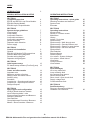
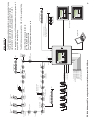
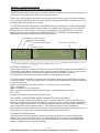
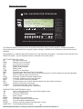
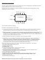
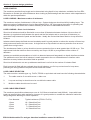
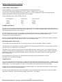
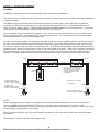
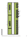
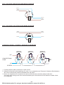
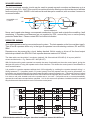
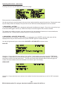
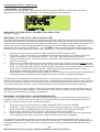
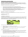
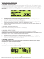
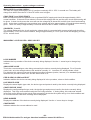
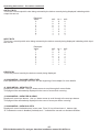
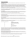
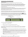
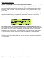
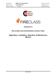
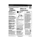
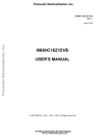
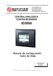
E ELECTRONIC
DEVICES
D LIMITED
ADDRESSABLE ALARM SYSTEM
TYPE ED 816A
ED816A SYSTEM
INSTRUCTION MANUAL
E
D
FIRE / GAS DETECTOR TYPE ED816A
14:29 27/11/06
POWER - IN LAMPS
AC - AC SUPPLY INPUT HEALTHY
DC MAIN - MAIN DC INPUT HEALTHY
DC AUX - OPTIONAL AUXILIARY DC INPUT
HEALTHY
ED816 ALARM SYSTEM
NO OF DETECTORS IN ALARM:
1 IN 1 ZONES
DETECTOR 1/ 1:
14:27 27/11/06 ENGINE ROOM
HEAT DETECTOR LOOP 2 ID 035 ZONE 2
PRE ALARMS 0
MAIN AUX
DC
CHR
FLT
FIRE / GAS ALARM
ALM PRE DEL
1
2
3
4
5
6
7
17
18
19
20
21
22
23
FIRE / GAS LAMPS
ALM - FIRE ALARM, GAS ALARM
PRE - PRE-ALARM LEVEL
DEL - DELAYED ALARM OPERATED
FLT - PANEL / LOOP / DEVICE FAULT
EVAC - EVACUATE
ISOL ZONES 0
FAULTS 0
POWER OUT
BATT
POWER IN
DC
AC
POWER - OUT LAMPS
DC - DC OUTPUT SUPPLY HEALTHY
BATT CHR - BATTERY CHARGING
BATT FLT - BATTERY FAULT / BATTERY
REQUIRES EXTERNAL CHARGING
PANEL / DEVICE STATUS
FLT EVAC MUTE ISOL DEL TEST COMMS
8
9
10
11
12
13
14
15
16
24
25
26
27
28
29
30
31
32
ZONES 1 - 32
PANEL / DEVICE STATUS LAMPS
MUTE - SOUNDERS HAVE BEEN SILENCED
ISOL - ISOLATED, ONE OR MORE ZONES
HAVE BEEN INHIBITED
DEL - ONE OR MORE DEVICE OUTPUTS
HAVE BEEN DELAYED
TEST - WHILST IN TEST MODE THE
ZONE UNDER TEST WILL NOT INITIATE
ALARMS. REMAINING ZONES WILL
CONTINUE TO FUNCTION NORMALLY
COMMS - COMMUNICATION FAULT
KEYS
- USE TO SCROLL THROUGH CURRENT
EVENTS AND NAVIGATE MENU
- USE TO NAVIGATE MENU
+/- - INCREMENT / DECREMENT
+
_
ENT
MENU EVAC MUTE RESET LAMP
TEST
ENT - ENTER / CONFIRM
MENU - MAIN MENU / PREVIOUS MENU
EVAC - EVACUATE OPERATES ALL OUTPUT
DEVICES
MUTE - SILENCE SOUNDERS
RESET - RESET SYSTEM TO NORMAL
CONDITION FOLLOWING ALARM / FAULT
LAMP TEST - PRESS TO TEST ALL LAMPS
MANUFACTURED BY ELECTRONIC DEVICES LTD., MALVERN, ENGLAND.
ENIGMA HOUSE, ENIGMA BUSINESS PARK, MALVERN, WORCESTERSHIRE WR14 1GD ENGLAND.
TELEPHONE : +44 (0) 1684 891500 FACSIMILE: +44 (0) 1684 891600 EMAIL: [email protected]
ED816A Addressable Fire and gas detection Installation manual 8-9-08 Rev-a
INDEX
INTRODUCTION
3
DESIGN, INSTALLATION & SETUP
OPERATING INSTRUCTIONS
SECTION 1
Component overview
ED722 and ED726 Loop Driver Module
ED816A Display Module
ED816A Input / Output Module
4
4
5
6
SECTION 2
System design guidelines
Loop lengths
Loop loading
Loop cable selection
Loop cable resistance
Loop cable capacitance
Screen continuity
Repeater cable selection
Power supply
7
7
7
7
7
8
8
8
8
SECTION 3
Control unit installation
General
ED816A I/O Module PCB connections
Detector Base wiring diagrams
Sounder wiring diagram
Repeater wiring diagram
9
9
10
11
11
12
SECTION 4
Initial system setup
PC based setup software (FireConfig.exe)
13
13
SECTION 5
Cause and effect matrix
Important note
Maximum number of entries
Adding cause and effect entries
Auxiliary relay
Sounders
Loop device - Sounders and beacons
Loop device - Input Output modules
Delayed Outputs
14
14
14
15
16
16
16
17
17
SECTION 6
Device types and configuration
XP95(A) North American models
Input Output modules / units
Loop powered Sounders and Beacons
Discovery Detectors
Gas Detection
Group Addressed Sounders / Beacons
Master / Slave Sounders / Beacons
18
18
18
18
18
19
19
19
SECTION 7
Operating Instructions - quick guide
Silencing sounders and beacons
System reset
Evacuate
20
20
20
20
SECTION 8
Operating instructions
Access levels
Switch on / Reboot screen
Main Menu
History
Isolate / De-isolate
System setup
System setup - Walk through test
System setup - Sounder Beacon test
System setup - Search for new devices
System setup - Set time and date
System Menu
Gas Detection
Delayed Alarms
Reboot system
Live values - System Voltages
Live values - Head Values
View faults
View pre-alarms
View isolates
21
21
21
22
22
22
23
23
23
24
24
24
24
25
25
25
26
28
28
28
SECTION 9
Fault messages
IO to loop cable fault
Loop continuity fault
No response from sensor
Sensor internal fault
Short circuit / Open circuit fault
Supply voltage fault
Communications fault
29
29
29
29
29
29
29
29
SECTION 10
Dual Redundancy
Discovery Conventional Mode /
Hardware Fire Detection
30
-2ED816A Addressable Fire and gas detection Installation manual 8-9-08 Rev-a
Isolating base
CO Fire
detector
Output module
EOL
Call point
Damper shutdown
HVAC shutdown
Switch monitor
Door switches
Fault monitored Flameproof Beacons and Sounders
Conventional Zone
ZONE MONITOR
Gas detector
interface
Gas sensor
Sounder circuit 3
Sounder circuit 2
Sounder circuit 1
Integrated
base sounder
Smoke
Heat
Zone monitor
Isolating base
Heat
Alarm relay contacts
Pre - Alarm relay contacts
Delayed Alarm relay contacts
Fault relay contacts
Auxiliary relay contacts
Auxiliary relay contacts
Auxiliary relay contacts
HWFD relay contacts to
additional Fire alarm Panels
Smoke
Smoke
LOOP 1
Isolating base
Multi sensor
Heat
Conventional Zone
E
D
Isolating base
Smoke
Remote
indicator
EOL
ED816 ALARM SYSTEM
18
17
19
3
20
21
5
CHR
22
6
FLT
POWER OUT
BATT
4
DC
+
23
7
25
9
_
ENT
ZONES 1 - 32
24
8
ALM PRE DEL
PANEL / DEVICE STATUS
ISOL ZONES 0
27
11
28
12
29
13
30
14
31
15
32
16
MENU EVAC MUTE RESET LAMP
TEST
26
10
FLT EVAC MUTE ISOL DEL TEST COMMS
FIRE / GAS ALARM
FAULTS 0
MANUFACTURED BY ELECTRONIC DEVICES LTD., MALVERN, ENGLAND.
2
MAIN AUX
1
AC
POWER IN
DC
PRE ALARMS 0
NO OF DETECTORS IN ALARM:
1 IN 1 ZONES
DETECTOR 1/ 1:
14:27 27/11/06 ENGINE ROOM
HEAT DETECTOR LOOP 2 ID 035 ZONE 2
14:29 27/11/06
KEYS
- USE TO SCROLL THROUGH CURRENT
EVENTS AND NAVIGATE MENU
- USE TO NAVIGATE MENU
+/- - INCREMENT / DECREMENT
ENT - ENTER / CONFIRM
MENU - MAIN MENU / PREVIOUS MENU
EVAC - EVACUATE OPERATES ALL OUTPUT
DEVICES
MUTE - SILENCE SOUNDERS
RESET - RESET SYSTEM TO NORMAL
CONDITION FOLLOWING ALARM / FAULT
LAMP TEST - PRESS TO TEST ALL LAMPS
PANEL / DEVICE STATUS LAMPS
MUTE - SOUNDERS HAVE BEEN SILENCED
ISOL - ISOLATED, ONE OR MORE ZONES
HAVE BEEN INHIBITED
DEL - ONE OR MORE DEVICE OUTPUTS
HAVE BEEN DELAYED
TEST - WHILST IN TEST MODE THE
ZONE UNDER TEST WILL NOT INITIATE
ALARMS. REMAINING ZONES WILL
CONTINUE TO FUNCTION NORMALLY
COMMS - COMMUNICATION FAULT
FIRE / GAS LAMPS
ALM - FIRE ALARM, GAS ALARM
PRE - PRE-ALARM LEVEL
DEL - DELAYED ALARM OPERATED
FLT - PANEL / LOOP / DEVICE FAULT
EVAC - EVACUATE
POWER - OUT LAMPS
DC - DC OUTPUT SUPPLY HEALTHY
BATT CHR - BATTERY CHARGING
BATT FLT - BATTERY FAULT / BATTERY
REQUIRES EXTERNAL CHARGING
Engineers PC
E
D
Level Detection
EOL
18
17
4
20
3
19
DC
21
5
CHR
22
6
FLT
POWER OUT
BATT
ED816 ALARM SYSTEM
+
23
7
25
9
_
ENT
ZONES 1 - 32
24
8
ALM PRE DEL
PANEL / DEVICE STATUS
ISOL ZONES 0
27
11
28
12
29
13
30
14
31
15
32
16
MENU EVAC MUTE RESET LAMP
TEST
26
10
FLT EVAC MUTE ISOL DEL TEST COMMS
FIRE / GAS ALARM
FAULTS 0
E
D
5
4
20
3
19
22
6
FLT
ED816 ALARM SYSTEM
+
23
7
9
25
_
ENT
ZONES 1 - 32
24
8
ALM PRE DEL
PANEL / DEVICE STATUS
ISOL ZONES 0
11
27
12
28
29
13
30
14
31
15
32
16
MENU EVAC MUTE RESET LAMP
TEST
26
10
FLT EVAC MUTE ISOL DEL TEST COMMS
FIRE / GAS ALARM
FAULTS 0
MANUFACTURED BY ELECTRONIC DEVICES LTD., MALVERN, ENGLAND.
2
18
1
21
CHR
POWER OUT
BATT
DC
MAIN AUX
17
AC
POWER IN
DC
PRE ALARMS 0
NO OF DETECTORS IN ALARM:
1 IN 1 ZONES
DETECTOR 1/ 1:
14:27 27/11/06 ENGINE ROOM
HEAT DETECTOR LOOP 2 ID 035 ZONE 2
14:29 27/11/06
EOL
KEYS
- USE TO SCROLL THROUGH CURRENT
EVENTS AND NAVIGATE MENU
- USE TO NAVIGATE MENU
+/- - INCREMENT / DECREMENT
ENT - ENTER / CONFIRM
MENU - MAIN MENU / PREVIOUS MENU
EVAC - EVACUATE OPERATES ALL OUTPUT
DEVICES
MUTE - SILENCE SOUNDERS
RESET - RESET SYSTEM TO NORMAL
CONDITION FOLLOWING ALARM / FAULT
LAMP TEST - PRESS TO TEST ALL LAMPS
PANEL / DEVICE STATUS LAMPS
MUTE - SOUNDERS HAVE BEEN SILENCED
ISOL - ISOLATED, ONE OR MORE ZONES
HAVE BEEN INHIBITED
DEL - ONE OR MORE DEVICE OUTPUTS
HAVE BEEN DELAYED
TEST - WHILST IN TEST MODE THE
ZONE UNDER TEST WILL NOT INITIATE
ALARMS. REMAINING ZONES WILL
CONTINUE TO FUNCTION NORMALLY
COMMS - COMMUNICATION FAULT
FIRE / GAS LAMPS
ALM - FIRE ALARM, GAS ALARM
PRE - PRE-ALARM LEVEL
DEL - DELAYED ALARM OPERATED
FLT - PANEL / LOOP / DEVICE FAULT
EVAC - EVACUATE
POWER - OUT LAMPS
DC - DC OUTPUT SUPPLY HEALTHY
BATT CHR - BATTERY CHARGING
BATT FLT - BATTERY FAULT / BATTERY
REQUIRES EXTERNAL CHARGING
POWER - IN LAMPS
AC - AC SUPPLY INPUT HEALTHY
DC MAIN - MAIN DC INPUT HEALTHY
DC AUX - OPTIONAL AUXILIARY DC INPUT
HEALTHY
FIRE / GAS DETECTOR REPEATER
MANUFACTURED BY ELECTRONIC DEVICES LTD., MALVERN, ENGLAND.
2
MAIN AUX
1
AC
POWER IN
DC
PRE ALARMS 0
NO OF DETECTORS IN ALARM:
1 IN 1 ZONES
DETECTOR 1/ 1:
14:27 27/11/06 ENGINE ROOM
HEAT DETECTOR LOOP 2 ID 035 ZONE 2
14:29 27/11/06
FIRE / GAS DETECTOR REPEATER
Conventional Zone 2
Up to 8 repeaters
Conventional Zones 1and 2
can be Safe Area, Hazardous Area,
Fire or level detection.
Conventional Zone 1
Contact Electronic devices limited on:
Tel: +44 (0)1684 891500
Fax: +44 (0)1684 891600
Email: [email protected]
-3-
The ED816A has an enclosure 365 x 340 x 110mm weighing 7.5Kg.
It is capable of driving up to 252 addressable devices per system in 2
loops of 126 devices per loop.
The ED816A Analogue Addressable Alarm system is capable of giving
Fire, Gas, Water and/or Engine alarms, operate Fire Fighting
equipment and is approved to Lloyds Register ENV1, 2, and 3.
POWER - IN LAMPS
AC - AC SUPPLY INPUT HEALTHY
DC MAIN - MAIN DC INPUT HEALTHY
DC AUX - OPTIONAL AUXILIARY DC INPUT
HEALTHY
FIRE / GAS DETECTOR TYPE ED816A
LOOP 2
Smoke
ED816A Addressable Fire and gas detection Installation manual 8-9-08 Rev-a
EOL
Gas detector
interface
Gas sensor
Isolating base
Beacon base
Smoke
Call point
Smoke
Gas detector
interface
Gas sensor
INTRODUCTION
Section 1 - Component overview.
ED722 and ED726 Loop Driver Module (ED816A Variation)
The ED722 and ED726 loop driver can provide 300mA of continuous loop current, driving up to
126 devices using Apollo S90, XP95 or Discovery protocol.
Each loop is fully isolated electrically from the input power supply, giving continued operation
in the event of earth faults on the dc input, greatly increasing immunity to electrical noise and
eliminating false alarms due to crosstalk.
The ED722 and ED726 are similar but the ED726 can also accept up to 10 EDL addressable
gas detection interface modules. Both models are available with front panels, as used in the
ED700A 8 Loop Control Panel, or without front panels for use in the ED816A. For the full
failsafe features to be available on the ED816A the ED722 / ED726 front panel lamps and
switches are relocated on the ED816A I/O motherboard.
Lamp Test button and backup Evacuate
Lamp Test button and backup Mute
button.
Lamp Test button and backup Reset
button.
Back up alarm / indicator lamps
(See below for usage)
EVACUATE MUTE
RESET
LOOP 1 STATUS
ALARM
PRE-ALM
DELAYED
FAULT
SILENCED
ISOLATED
POWER
EVACUATE MUTE
RESET
LOOP 2 STATUS
ALARM
PRE-ALM
DELAYED
FAULT
SILENCED
ISOLATED
POWER
FAIL SAFE OPERATION
Each module within the system (ED722/6 loop modules, ED816A Display module and ED816
I/O module) communicate with each other using an industry standard I2C bus. In the event of
a communications failure, or a fault developing on any of the modules, creating a
communications failure, the loop cards continue to operate autonomously.
The loop modules are directly connected to the following normally energised relays mounted
on the IO module. These should be used for all safety critical operations as they are operated
in the fail safe mode.
HWFD = normally open contact closing to 470 ohms in the alarm condition.
PRE = Pre-alarm.
IMM = Immediate Fire or Gas Alarm.
DEL = Operates 2 minutes after an alarm if mute or reset has not been pressed.
FLT = Fault.
Sounder 1 is directly connected to the alarm relay.
DISCOVERY CONVENTIONAL MODE (Hardware Fire Detection HWFD)
Not to be confused with conventional fire zones, conventional mode, built into the Discovery
detectors and Electronic Devices gas detector interface, provides continued alarm detection in
the event of limited circuit failure. E.g. Microprocessor failure on the loop module resulting in
panel to detector communications failure. Conventional mode becomes operational
approximately 2 minutes after loop to detector communications has failed. Electronic Devices
recommend using Discovery detectors to take advantage of this feature.
PUSH BUTTON OPERATION
If pressed under normal operating conditions the three push buttons operate as lamp test
buttons only. However in the event of a communications error or fault on the Addressable
display module, the loop cards continue to operate autonomously and the push buttons will
function as labelled. See page 29 for details.
-4ED816A Addressable Fire and gas detection Installation manual 8-9-08 Rev-a
ED816A Display Module
E
D
FIRE / GAS DETECTOR TYPE ED816A
14:29 27/11/06
POWER - IN LAMPS
AC - AC SUPPLY INPUT HEALTHY
DC MAIN - MAIN DC INPUT HEALTHY
DC AUX - OPTIONAL AUXILIARY DC INPUT
HEALTHY
ED700 ALARM SYSTEM
NO OF DETECTORS IN ALARM:
1 IN 1 ZONES
DETECTOR 1/ 1:
14:27 27/11/06 ENGINE ROOM
HEAT DETECTOR LOOP 2 ID 035 ZONE 2
PRE ALARMS 0
POWER IN
DC
FIRE / GAS LAMPS
ALM - FIRE ALARM, GAS ALARM
PRE - PRE-ALARM LEVEL
DEL - DELAYED ALARM OPERATED
FLT - PANEL / LOOP / DEVICE FAULT
EVAC - EVACUATE
ISOL ZONES 0
FAULTS 0
FIRE / GAS ALARM
POWER OUT
BATT
POWER - OUT LAMPS
DC - DC OUTPUT SUPPLY HEALTHY
BATT CHR - BATTERY CHARGING
BATT FLT - BATTERY FAULT / BATTERY
REQUIRES EXTERNAL CHARGING
PANEL / DEVICE STATUS
DC
CHR
FLT
1
2
3
4
5
6
7
8
9
10
11
12
13
14
15
16
17
18
19
20
21
22
23
24
25
26
27
28
29
30
31
32
AC
MAIN AUX
ALM PRE DEL
FLT EVAC MUTE ISOL DEL TEST COMMS
ZONES 1 - 32
+
_
ENT
MENU EVAC MUTE RESET LAMP
TEST
PANEL / DEVICE STATUS LAMPS
MUTE - SOUNDERS HAVE BEEN SILENCED
ISOL - ISOLATED, ONE OR MORE ZONES
HAVE BEEN INHIBITED
DEL - ONE OR MORE DEVICE OUTPUTS
HAVE BEEN DELAYED
TEST - WHILST IN TEST MODE THE
ZONE UNDER TEST WILL NOT INITIATE
ALARMS. REMAINING ZONES WILL
CONTINUE TO FUNCTION NORMALLY
COMMS - COMMUNICATION FAULT
KEYS
- USE TO SCROLL THROUGH CURRENT
EVENTS AND NAVIGATE MENU
- USE TO NAVIGATE MENU
+/- - INCREMENT / DECREMENT
ENT - ENTER / CONFIRM
MENU - MAIN MENU / PREVIOUS MENU
EVAC - EVACUATE OPERATES ALL OUTPUT
DEVICES
MUTE - SILENCE SOUNDERS
RESET - RESET SYSTEM TO NORMAL
CONDITION FOLLOWING ALARM / FAULT
LAMP TEST - PRESS TO TEST ALL LAMPS
MANUFACTURED BY ELECTRONIC DEVICES LTD., MALVERN, ENGLAND.
The ED816A Display module provides all system information during normal operation. Detailed information
about each device connected to the system, system voltages, Isolated zones, delay times and function are all
available.
Also available is a Marine approved Repeater unit, with identical functionality, connected to the main panel via
RS485 full duplex. Up to 8 repeaters can be connected to the main system.
LED FUNCTION (left to right)
AC
AC mains connected.
MAIN
Main DC input connected.
AUX
Aux DC input connected.
DC
Fused DC output okay.
CHR
Battery being charged.
FLT
Battery fault.
FIRE
Main Fire or Gas Alarm.
PRE
Pre alarm early warning of Fire or Gas Alarm.
DEL
Delayed Alarm, Fire or Gas Alarm has been present for 2 minutes without being acknowledged.
FLT
Fault on System, wiring or loop device.
EVAC
Evacuate condition has been implemented.
MUTE
Sounders / Beacons have been silenced.
ISOL
1 or more zones have been isolated.
DEL
Delayed output, one of the 8 delayed outputs will action after preset time.
TEST
System is currently in test mode.
COMMS
Communications failure has occurred.
1 - 32
Zone LEDs, indicating a Fire / Gas alarm.
PUSH BUTTON FUNCTION(left to right)
Use to scroll through current events and navigate menu.
Use to navigate menu.
+/Increment / decrement.
ENT
Enter confirm.
MENU
Previous menu / main menu.
EVAC
Evacuate, operates all output devices.
MUTE
Turn off Sounders and Beacons.
RESET
Reset to normal condition following alarm or fault.
LAMP TEST Test all Display Module lamps.
-5ED816A Addressable Fire and gas detection Installation manual 8-9-08 Rev-a
ED816A Input / Output Module
The Input / Output module provides all of the facilities required for most applications, eliminating the need to
purchase additional add-on modules or interface units.
Designed with ease of installation in mind the I/O Module is fitted with large terminals capable of easily
accepting 4mm square conductors.
MAINS MAIN
AC
DC
AUX
DC
PC
DC
OUT SETUP
1 - 8 FIRE / GAS
LOOPS
3 SOUNDER CCTS
I/O MODULE
REPEATERS
HARDWARE FIRE / GAS
DETECTION (HWFD)
TO ADDITIONAL
FIRE / GAS PANELS
2
CONVENTIONAL
ZONES
ALARM PRE FAULT DELAY 3 AUX
VFC ALARM VFC ALARM RELAY
VFC
VFC
VFC
The I/O module provides the following:
Loop input / output terminals for up to 2 loops.
2 x Conventional Fire Detection Zones, ideal for utilising existing conventional detectors when retro fitting.
Suitable detectors are Apollo S60 / S65, Apollo Orbis, Tyco M600 and the Hochiki CDX range.
1 x RS232 Comms port for connection to a PC or a laptop running Electronic Devices FireConfig.exe Windows
software Application. Use a straight through (not null modem) serial cable with a 9 pin D type male
connector on one end and female on the other. If using a laptop which does not have a suitable serial port
you will also need a USB to Serial port converter.
1 x RS485 Full Duplex Comms port for connection to up to 8 Repeater modules.
1 x HWFD Relay Output, (Hardware Fire Detection). Normally energised relay output for connection to
additional control panels or third party conventional / addressable fire panel. The HWFD contacts are
normally open and close to 470 Ohms in the event of an alarm condition. Importantly this relay will
continue to operate correctly in the event of internal panel communications failure and also loop
communications failure (discovery detectors and EDL gas detectors only).
All relays are Voltage free change over contacts. All are rated at 2.5A @ 30V d.c. non inductive.
1 x Fire Alarm Relay, fail safe hardware driven.
1 x Delayed Fire Alarm Relay.
1 x Pre Alarm Relay.
1 x Fault Alarm Relay contacts.
3 x Auxiliary Alarm Relay contacts, 3 Relays each with 2 sets of
Contacts. Configurable using PC application.
3 x Monitored Sounder Circuits rated 1A ; 24V dc. Sounder circuit 1 is fail safe, hardware driven.
Sounder circuits 2 and 3 are software driven and configurable.
2 x 24V DC Monitored Fused Outputs.
1 x Auxiliary DC Monitored Input, 24V dc +/- 25%..
1 x Battery Input with automatic charging and disconnection before battery damage can occur.
1 x Main DC Monitored Input, normally used with the internal Power Supply, 24V dc +/- 25%..
1 x Main AC Monitored Input.
1 x Internal Buzzer (comms failure).
-6ED816A Addressable Fire and gas detection Installation manual 8-9-08 Rev-a
Section 2 - System design guidelines
LOOP LENGTHS
The maximum permitted loop length can be determined using Apollo’s loop calculator, available free from EDL.
Remember to include the vertical distances when looking at plan drawings and also ensure cable capacitance is
within the panels specification.
LOOP LOADING - Maximum number of addresses
The maximum number of addresses is 126 per loop. System designers should avoid fully loading loops. The
optimum number of addresses per loop is approximately 90 to 100, this ensures the system is operating well
within its capacity and allows the customer flexibility in the future to add additional devices.
LOOP LOADING - Short circuit isolators
Short circuit isolators should be fitted with no more than 20 detectors between isolators. No more than 10
detectors (or equivalent load) between the panel and the first isolator and no more than 10 detectors (or
equivalent load) between the panel and last isolator. Ideally the first and last items fitted to a loop should be
isolators.
Isolators should always be fitted at zone boundaries and it is good practice to reduce the number of times loop
wiring enters and leaves the same zone. A single fault on a loop should not remove protection from an area
greater than a single zone.
Two simultaneous faults on a loop should not remove protection from an area greater than 10,000 sq m . This
requirement limits the total floor area covered by one loop to 10,000 sq m regardless of the number of
detectors.
Isolators are available as standalone or built in to detector bases and integrated in to Apollo interface modules .
The additional cost of the built in isolators is small compared to the non isolated bases or interface units
therefore as many isolators should be fitted as possible.
Short circuit isolators do not use up addresses and there is no limit to the number of isolators fitted.
Each loop card is fitted with two onboard short circuit isolators, one for loop out and one for loop return,
protecting the wiring between the panel and first and last isolator.
LOOP CABLE SELECTION
The cable must be a suitable type e.g. FireTuf, FP200 or equivalent and must have the following characteristics:
1.
The cable must be 2 core with screen + drain core.
2.
Loop out and loop in should never be run within the same cable.
3.
Multicore cable should never be used.
LOOP CABLE RESISTANCE
The maximum permissible resistance per core is 12.8 Ohms at maximum load (300mA). Loops with lower
loads can accept higher cable resistance, however it is good practice to consider the maximum load at the
design stage thus allowing for future expansion.
Core diameter
Typical resistance (FP200 / FireTuf)
1.0mm
1.5mm
2.5mm
4.0mm
18.1 Ohms/Km/Core
12.1 Ohms/Km/Core
7.4 Ohms/Km/Core
4.6 Ohms/Km/Core
-7ED816A Addressable Fire and gas detection Installation manual 8-9-08 Rev-a
System design guidelines - continued
LOOP CABLE CAPACITANCE
Cable capacitance is an important consideration when choosing loop cable.
The maximum permissible capacitance is 0.5uF (500nF) between loop + and loop -.
As each loop is electrically isolated therefore high loop to screen capacitance does not normally cause a
problem and should not be the limiting factor for loop lengths.
Typical capacitance per 100m (FP200 / FireTuf)
Core diameter
core to core
core to screen
1.0mm
1.5mm
2.5mm
10nF
12nF
13nF
17.5nF
20.5nF
24.0nF
SCREEN CONTINUITY
It is vital, for correct and trouble free operation, that the screen is continuous along the full loop length. Ensure
that the screen connection is continued at each loop device. The screen should be earthed at one end only, via
the control panel, and never at loop devices.
All cables entering the control unit should be screened and ferrite sleeves, supplied with the control unit, must
be used. All screens should be terminated at the control panel only thereby avoiding earth loops.
See page 9 for connection diagram.
Note the repeater data cable screens must NOT be connected to the enclosure (earth) and instead connected
to the terminals marked SCRN inside the control unit and repeater units.
REPEATER CABLE SELECTION
The repeater communicates with the control panel using the industry standard RS485 full duplex.
The data cable used should be 2 conductor (twisted) 124 Ohm twinixial 25 AWG (0.16 sq mm) with foil screen
and drain wire. E.g. Beldon 9271 006 (BLULT).
Repeaters can be powered locally to avoid running additional power cables or they can be powered from the
control unit using the fused output terminals. Up to 8 repeaters can be connected to each system, however if
powered from the control panel the repeater current consumption should be included in power supply and
battery calculations.
Each repeater can operate from 18 - 30Vdc with a worst case current consumption of 350mA.
See page 10 for connection diagram.
POWER SUPPLY
The control unit requires a nominal 24V dc supply and must always have batteries connected. Normally the AC
mains is connected to the AC mains input terminals and the AC mains output terminals are wired to the external
power supply. The power supplies DC output is connected to the systems main DC input terminals.
Auxiliary DC input terminals are provided as an additional option. The DC input and Auxiliary (if used) must be
suitably rated to charge the internal batteries.
All power supply cables must be screened and ferrite rings used and cables should not be routed near EMC
generating equipment, radio transmitters, paging systems etc., See page 9.
-8ED816A Addressable Fire and gas detection Installation manual 8-9-08 Rev-a
Section 3 - Control unit installation
GENERAL
WARNING: Please read this section completely before commencing installation.
The panel must be located in a clean, dry position at least 2 metres away from any radio transmitting equipment
e.g Pager systems.
The Mains supply should be installed in accordance with the current edition of the IEE wiring regulations.
Connection to the mains supply must be via an isolating protective device (e.g. an isolating fuse) reserved
solely for the fire alarm system. It should be insured that all isolating switches, circuit breakers etc., connected
to the system should be labelled “FIRE ALARM DO NOT SWITCH OFF”.
Correct earthing is vital for trouble free operation. The earth connection should be as short as possible, using
4mm square conductors, connected directly to a good quality earth. The earth should not be routed via radio
transmitting devices or other electrical equipment.
All cables entering the control unit should be screened and ferrite sleeves, supplied with the control unit, should
be used. All screens should be terminated at the cable gland. Only metal, EMC shielding cable glands should
be used. Screens should be continuous and have continuity along the entire length of the cable. Only connect
the screen to earth at one end thus avoiding earth loops. All unscreened conductors should be kept as short as
possible and the ferrite ring should be as close to the cable gland as possible. Wrap each conductor around the
ferrite at least twice. Any communication faults experienced are likely to be caused by poor EMC shielding
practices. Repeater cable screens should never be connected to earth, always use the terminals provided.
ZONE 1
ZONE 32
ISOLATOR
ISOLATOR
ZONE 2
SCREEN CONNECTED
TO METAL CABLE GLAND
ISOLATOR
ISOLATOR
SHORT CIRCUIT ISOLATORS ARE
ALWAYS THE FIRST AND LAST
DEVICE ON A LOOP AND SHOULD
ALWAYS BE USED AT ZONE
BOUNDARIES.
SCREEN NOT EARTHED
AT THIS END
ENSURE GOOD
CONNECTION BETWEEN
GLAND AND ENCLOSURE
CONDUCTORS WRAPPED
AROUND FERRITE CORE
LOOP OUT
LOOP IN
NOTE
When changing any plug-in cards or loop devices, observe anti-static precautions. Ensure that all power is
removed and the system is switched off. Failure to do so may result in damage to the cards or panel.
The panel MUST be switched off before removing or replacing any card or module. Failure to observe this may
cause damage to the printed circuit boards.
Each loop card has an ID, set via the dip switches mounted on each loop card. No two loop card should have
the same ID.
FireConfig.exe must be used for initial system setup.
-9ED816A Addressable Fire and gas detection Installation manual 8-9-08 Rev-a
HWFD
-
SCRN
B
A
SCRN
Y
Z
ALARM
PREALARM
FAULT
RELAY CONTACTS
DELAYED
ALARM
AUX # 1
AUX # 3
AUX # 5
+
+
-
+
-
+
-
+
-
+
-
+
SOUNDER
SOUNDER
MAIN
24V
OUTPUT
OUTPUT
24VDC
BATTERY
NO. 1
NO. 3
INPUT
INPUT
SOUNDER
FUSED 24VDC AUX
OUTPUT
OUTPUT
24VDC
NO. 2
INPUT
-
-
RESET
LOOP 2 STATUS
EVACUATE MUTE
C NO NC C NO NC C NO NC C NO NC C NO NC C NO NC C NO NC
+
LOOP 1 STATUS
-
RESET
+
EVACUATE MUTE
ALARM
PRE-ALM
DELAYED
FAULT
SILENCED
ISOLATED
POWER
L
N
E
N
E
MAIN
AC
OUTPUT
L
LOOP 2
IN
OUT
MAIN
AC
INPUT
CONVENTIONAL
Z1
Z2
+
LOOP 1
IN
OUT
-
ALARM
PRE-ALM
DELAYED
FAULT
SILENCED
ISOLATED
POWER
+
CONVENTIONAL
LOOP 2
CONNECTIONS CONNECTIONS
-
PC CONNECTION
-
LOOP 2
CONNECTIONS
+
REPEATER
CONNECTIONS
-
ED816A I/O BOARD CONNECTIONS
+
ED816A Addressable Fire and gas detection Installation manual 8-9-08 Rev-a
-10-
XP95 / DISCOVERY MOUNTING BASE WIRING DIAGRAM
LOOP -VE
SCREEN
LOOP +VE
EARTH
L2
L1
-R
+R
LOOP -VE
SCREEN
LOOP +VE
XP95 / DISCOVERY ISOLATING BASE WIRING DIAGRAM
SCREEN
SCREEN
LOOP +VE
LOOP +VE
EARTH
L2
IN
L1
OUT
LOOP -VE
LOOP -VE
-R
CONVENTIONAL ZONES
+R
WIRING DIAGRAM
REMOTE
INDICATOR
REMOTE
INDICATOR
REMOTE
INDICATOR
+VE
IN +
LE
D
T
OU
LE
D
-
-
M
CO
T
OU
LE
D
IN +
-
CO
T
OU
APOLLO
ORBIS
APOLLO
ORBIS
APOLLO
ORBIS
4
4
4
+
+
+
CONVENTIONAL
ZONE
M-
IN +
-
MCO
4K7
EOL
-VE
SCREEN
1. Connect detector earth connection to cable screen
2. Always fit call points at the beginning of a zone or on a separate zone. Removal of detectors fitted between
the control unit and call points would disable the call points.
3. Never use looped wire for connection into and out from the same terminal, always break wire.
Any single wire coming loose from a terminal should open circuit the end of line resistor to enable a fault
to be indicated.
-11ED816A Addressable Fire and gas detection Installation manual 8-9-08 Rev-a
SOUNDER WIRING
The fault monitored sounder circuits can be used to operate several sounders and beacons up to a
maximum load of 1A. A 4K7 Ohm end of line resistor should be fitted across the last device to facilitate
fault monitoring. Note: SNDR1 is fail safe and should always be used first, with sounders / beacons in
a manned location.
+VE
SOUNDER CCT
1,2 OR 3
-VE
+
+
+
+
-
SND 1
-
SND 1
-
SND 2
-
SND 2
+
+
ED6 SOUNDER /
BEACON COMBINATION
ED6 SOUNDER
4K7
EOL
-
ED6 BEACON
Never use looped wire always use separate conductors for input and outputs thus enabling fault
monitoring. If Sounders and Beacons are not supplied by EDL, ensure they have a series polarity
protection diode fitted. Please contact EDL for further information.
REPEATER WIRING
Up to eight repeaters can be connected to each system. The last repeater on the line must be a type A.
Type A and B repeaters differ only in that type A repeaters have terminating resistors, R2 and R39,
fitted.
Repeaters can be powered by a local, battery backed, 24Vdc supply or driven off the fused output
terminals provided in the ED816A. Each repeater draws a maximum of 350mA.
The data cable used should be 2 conductor (twisted) 124 Ohm twinixial 25 AWG (0.16 sq mm) with foil
screen and drain wire. E.g. Beldon 9271 006 (BLULT).
With full duplex wiring each repeater has exactly the same functionality as the main control panel, giving the
designer the option of using the repeater as the main interface. This allows the control panel to be situated in a
more central location.
It is possible to operate repeaters without their full functionality by omitting the repeater transmit wiring; i.e.
Wiring between Z, Y (repeater) and A, B (control panel).Thus the repeater can only receive information, no
information can be transmitted to the control panel including setup information etc.. Electronic Devices Limited
do not recommend this method because the EVAC button on the repeater will not function. However a solution
is to have a call point located next to the repeater set to “no zone”. Call points set to no zone automatically
operate the evacuate command when operated. It is for this reason all repeaters installed should be checked
they both transmit data as well as receive it from the control panel.
RS485 FULL DUPLEX
SCRN
B
A
RX
TX
SCRN
Z
Y
TX
SCRN
Z
Y
TX
SCRN
Z
Y
SCRN
Z
Y
TX
RX
SCRN
B
A
RX
SCRN
B
A
RX
SCRN
B
A
24V FUSED
OUTPUT
+
-
CONTROL PANEL
+
-
REPEATER
TYPE B
+
-
REPEATER
TYPE B
-12ED816A Addressable Fire and gas detection Installation manual 8-9-08 Rev-a
+
-
REPEATER
TYPE A
Section 4 - Initial system setup
FIRECONFIG
Fireconfig.exe is a windows based application program which MUST be used for initial system setup.
Install FireConfig.exe on to your Windows XP / Vista PC hard drive or run directly from a data stick if required.
Use a straight through (not null modem) serial cable with a 9 pin D type male connector on one end and female
on the other. If using a laptop which does not have a suitable serial port you will also need a USB to Serial port
converter.
1.
Check the loop fitted boxes for all loops fitted. (For the ED816A only loop 1 and 2 are applicable.)
2.
Click “Configure” for loop 1.
3.
Click “Add Head” and then fill in the details for the first addressable device on the loop.
4.
Choose the address, which can be 1 to 126.
5.
Choose the name, which can be a maximum of 12 characters.
6.
Choose the zone, which can be 1 to 32. Additionally No Zone can be specified. Any device going in to alarm,
which has not had a zone assigned, will operate the evacuate command and all sounders and beacons will
operate. Additionally no delays or zone isolates are allowed.
-13ED816A Addressable Fire and gas detection Installation manual 8-9-08 Rev-a
Initial setup - continued
When choosing some devices additional check boxes / drop down menus may appear, eg. Discovery
sensitivity. See DEVICE TYPES AND CONFIGURATION (page 14) for further details.
7.
Repeat steps 2 - 6 until all loops are configured.
9.
Click “Display Names” and choose the text that appears in the top right hand side of the display for both
main panel and repeaters.
10.
Click “Power Supplies” and check the appropriate boxes. If not checked the system will not give fault
warnings for that particular supply.
11.
Click “Conventional Zones”, if used, and choose whether the zone is to be used for Hazardous or safe
Areas. If “Intrinsically Safe Devices” are chosen the zone wiring must be connected through an
Electronic Devices zener barrier type ZBD7+ located in the Safe Area. See connection diagram and
also ensure ATEX regulations are met fully.
12.
Click “Save” to save the configuration to you computers hard drive or data stick.
13.
Click “Export” to save the configuration to .csv format which can be read and printed using most spread
sheet programs e.g. Microsoft excel or openoffice (freeware available from www.openoffice.org).
14.
Click “Options” to select which comms port your serial cable is attached to. Click test to check both the
port and system are working correctly.
15.
Click “Clear configuration” if the system has previously been configured and now requires
changing. This will take several minutes and will CLEAR ALL information held in memory.
16.
Click “Erase History” to clear the history stored in the systems memory.
17.
Click “Download” to send the data in to the system. This can take several minutes. Once complete turn
the system off for one or two seconds before turning back on. Monitor the system closely for the next
several minutes, checking for any faults to be reported. Most faults will be reported within 2 minutes,
however internal memory and program errors can take up to 1 hour to be reported.
If downloading is interrupted (power failure, pc failure etc.) turn off the systems power and then after a
few seconds, re-power the system and, when ready, start the download again.
Section 5 - Cause and Effect Matrix
The Cause and Effect matrix does not have to be used for simple applications. However for the needs of larger
and more complicated systems a powerful cause and effect matrix is provided.
IMPORTANT NOTE
It is important to note that in the event of panel failure or communications failure the cause and effect matrix will
not function. SNDR1 is the dedicated fire/gas alarm which is operated in failsafe mode and also via the
HardWare Fire Detection circuit. The HWFD circuit will continue to give alarms from Discovery detectors and
EDL gas detectors in the event of communication failure between panel and loop devices, provided the loop
voltage is still correct. Therefore SNDR1 should be the first choice and should always be used with at least
one sounder located in a manned area. See page 30.
MAXIMUM NUMBER OF ENTRIES
No more than 50 cause and effects should be used. To help reduce the number of cause and effects the
following methods should be used:
1.
All sounders, beacons, sounder control units etc., that are to operate from the main fire/gas Alarm
should have the “always operate in the event of alarm” check box ticked on the loop configuration page.
If this is done no cause and effect entries are necessary.
2.
All I/O controllers and Switch monitor I/O modules with inputs only being used to operate the main
fire/gas Alarm, should have the appropriate “alarm on bit 0,1 or 2” boxes checked on the loop
configuration page. If this is done no cause and effect entries are necessary.
3.
If large numbers of loop powered sounders / beacons are to operate from any cause other than the
main fire/gas alarm (e.g. Pre-alarm), group addressing and / or master - slave sounders / beacons
should be used so that only minimal cause and effect entries are required.
-14ED816A Addressable Fire and gas detection Installation manual 8-9-08 Rev-a
Cause and Effect Matrix - continued
Adding Cause and Effects entries
1.
Click “Cause and Effect” and then “add Entry”.
2.
Choose a name for the entry.
3.
Select the “input type”.
“Device” is any detector, input module, zone
monitor or switch monitor on any loop.
“Zone” is any of the 32 zones and also either of the
2 built in conventional zones.
“Loop” is any of the loops attached to the system
only loop 1 and 2 apply for the ED816A.
4.
Select “Cause”. Cause can be pre-alarm, alarm
or fault.
If Zone was chosen for input type an extra cause
choice becomes available. “Coincidence”
detection is available between any 2 zones.
In the event of the 2 zones chosen both being in
the alarm condition then the effect will be actioned.
If Device was chosen for input type and the device is an I/O module, 2 extra cause choices become
available. I/O unit Latching and I/O unit Non-Latching.
Apollo manufacture 3 main I/O modules with the following inputs:
I/O module
Mains switching I/O
input bits
0
1
2
FireConfig input
1
2
3
use
status of monitored switch
not used
not used
Input Output Unit
0
1
2
1
2
3
status of monitored switch
status of opto input
not used
3 Channel Input Output Unit
0
1
2
1
2
3
status of monitored switch 1
status of monitored switch 2
status of monitored switch 3
Whilst the monitored switch is open no effect will occur, once the switch closes the chosen effect takes
place.
When choosing “I/O unit Latching” the effect will remain until RESET has been pressed, any
effect can be chosen from the drop down box.
When Choosing “I/O unit Non-Latching” the effect will remain for only as long as the input is set. Only
Loop Devices can be chosen in the “Effect” drop down box. When operating a loop output device only
one non-latching cause can be assigned to it.
5.
Select Output type in the “effect” dialogue box, which can be Aux Relay, Sounder, Loop Device or
Delayed Output.
-15ED816A Addressable Fire and gas detection Installation manual 8-9-08 Rev-a
Cause and Effect Matrix - continued
Aux Relay
There are 3 Auxiliary relays located on the ED816A Input / Output module, each with 2 sets of voltage free
contacts. (Note the ED816A has 1 set of voltage free contacts per aux relay.)
Sounders
There are 3 monitored sounders on the ED816A Input / Output module. SNDR1 is the dedicated fire/gas alarm
which is operated in failsafe mode and also via the HardWare Fire Detection circuit. The HWFD circuit will
continue to give alarms, from Discovery detectors and EDL gas detectors, in the event of communication failure
between panel and loop devices, provided the loop voltage is still correct. Therefore SNDR1 should be the first
choice and should always be used with at least one sounder located in a manned area.
Sounders 2 and 3 are configurable via FireConfig.
Loop Device
When choosing loop device in the “effect” dialogue box it is possible to select any addressable device.
However care should be taken to only select suitable devices e.g. Sounders, beacons and output
modules. The following guidelines should be observed:
Sounders and beacons
When choosing loop powered sounders / beacons as
output devices the set tone drop down box appears.
Allowing the commissioning engineer to choose which
output bits are set and hence the tone to be used.
Refer to the Apollo data sheets for individual sounder /
beacon types, below are the most common examples:
100dB loop powered sounder
Output bit
Action
0
continuous tone
1
pulsed tone
0+1
continuous tone
Intelligent base sounder
Output bit
Action
0
alternates 510hz / 610hz
1
intermittent 510hz
0+1
alternates 510hz / 610hz
Ancillary base sounder
Output bit
Action
0
continuous tone
1
not used
0+1
not used
To avoid confusion it is important to ensure all sounders use the same tones (or as similar as possible) to signal
the same condition.
-16ED816A Addressable Fire and gas detection Installation manual 8-9-08 Rev-a
Cause and Effect Matrix - continued
Apollo Input Output modules and Output modules
When choosing Input / Output and Output modules as
output devices the output bit drop down box appears,
allowing the commissioning engineer to choose which
output bits are set and hence the Relay to be switched.
Please note output bits are referred to as output 1,2 and 3
in FireConfig but as output bits 0,1 and 2 in Apollo’s literature.
Refer to the Apollo data sheets for individual module
types, below are the most common examples:
Mains Switching Input Output unit
Output bit
Action
0
relay drive
1
not used
2
not used
FireConfig Output
1
2
3
3 channel Input Output unit
Output bit
Action
0
channel 1 relay
1
channel 2 relay
2
channel 3 relay
FireConfig Output
1
2
3
Delayed Output
When choosing delayed output in the “effect”
drop down box it is possible to setup up to 8
delayed effects. The 8 delayed effects can be
called as many times as required by different
cause and effect entries, remembering 50
entries is the maximum number of cause and
effects allowed.
The “configure delayed outputs” button is at
the bottom of the main cause and effects
page and brings up the dialogue box shown.
Delays can be set anywhere between 1 and
600 seconds.
It is important to ensure all fire / gas
detection standards are not infringed when
adding delays. E.g. EN54-2 stipulates what
can and cannot be delayed when outputs are
connected to “fire alarm routing equipment”.
It is possible to override delays at any stage during normal operation by choosing item 6 (delayed outputs) from
the main system menu. It should also be remembered that, from within the cause and effect matrix, a dedicated
and suitably labelled call point could be assigned the same 8 outputs but without delays thereby giving an easy
method to override the delays. Additionally pressing the “EVAC” button or any call point not assigned a zone
will operate the evacuate command and all loop powered sounders, beacons, sounders circuits and Immediate
Alarm, Pre-Alarm and Delayed output relays will operate.
-17ED816A Addressable Fire and gas detection Installation manual 8-9-08 Rev-a
Section 6 - Device types and configuration
The ED722 and ED726 Loop drivers communicate with loop devices using Apollo Fire Detectors Ltd., protocol
S90, XP95 and Discovery.
For most devices it is obvious what selection to
make when adding to FireConfig. However it
may not be immediately obvious for some devices
which is why the device type code is shown in
brackets. e.g. Discovery optical smoke detectors
are type code 160. All Apollo devices have a type
code telling the control panel what the device is and
how it operates. If you cannot find a
particular device in FireConfig contact EDL
or Apollo and obtain the device code.
Additional drop down boxes appear when
selecting some devices and fall in to four
Categories. Input Output units, Sounder / Beacons,
Discovery detectors and Gas Detection.
XP95(A) North American Models
XP95(A) the protocol used in North America, is also supported, allowing Apollo devices to be purchased directly
from the USA.
Apollo Input Output modules / units
When adding Input Output units three check boxes
will appear. “Alarm on bit 0,1 or 2”. Consult the
data sheet and choose which bits, if any, you
require to operate the main Fire / Gas alarm. Cause
and effect entries are not required if these boxes
are ticked.
Check the “never generate alarm” box if the main
Fire / Gas alarm is not required and cause and
effect entries are to be used instead.
By adding suitable cause and effect entries it is
possible for an input module (e.g. Monitoring an
Emergency Exit switch) to operate an output module on any loop silently without any front panel indication,
buzzers etc., operating.
Loop powered Sounder and Beacons
When adding Sounders and Beacons the “Always operate sounder in event of alarm” check box appears.
Always check this box for operation from the main Fire / Gas alarm and no cause and effect entries will be
required. If left unchecked the device will only operate if a suitable cause and effect entry has been made.
Discovery Detectors
All Discovery detectors have 5 modes of operation to choose from, changing sensitivity, time to respond and for
the multi-sensor whether it reacts to heat or smoke only or both.
-18ED816A Addressable Fire and gas detection Installation manual 8-9-08 Rev-a
Device types and configuration - continued
Gas Detection
When adding EDL Gas Detection three dialogue
boxes will appear. Sensor range, Pre-Alarm limit
and Alarm limit. When choosing the sensor range
ensure the sensor is capable of operating correctly
within that range. Pre-Alarm and Alarm limits are
the value that the gas sensor has to reach before
the alarm is given. Both alarm and pre-alarm can
be set between 10% and 80% of the sensors range
(full scale value) in 10% steps.
Group Addressed Sounders and Beacons
Some Apollo Sounders and Beacons are available with a second set of dip switches used for group
addressing., the address must be in the range of 112 - 126. This feature is useful when operating several
sounders from a single cause and effect or when adding to an existing system without the need to connect to a
PC. Group addressing should be setup as follows:
1. Add a Sounder or Beacon with its individual address in the range 112 - 126 using FireConfig
setup software. Ensure this device is NOT group address enabled by setting the group address dip
switches to “0000”.
2. Add a cause and effect entry to operate the device and / or tick the “always operate in the event of
alarm” check box.
3. All additional Sounders / Beacons to be included in this group should be added with their individual
addresses in the range 1 - 126 and the group address dip switch should be set to the address
chosen in 1 above. Additional sounders / beacons can be added either by using the FireConfig software
or using the “search for new devices” function from the main panel or any repeater.
4. Group addressing can only operate on the same loop.
5. Please see Apollo data sheets for more information.
Master / Slave Sounders and Beacons
Some Apollo Sounders and Beacons are available with an additional dip switch for selecting “Master” or “Slave”
mode. The feature is has similar benefits to using group addressing but should not be confused with group
addressing as the setup is different. Master / Slave sounders should be setup as follows:
1. Add a Sounder or Beacon with its individual address in the range 1 - 126 using FireConfig
setup software. Ensure this device is set as “master” using the appropriate dip switch.
2. Add a cause and effect entry to operate the device and / or tick the “always operate in the event of
alarm” check box.
3. Additional Sounders or Beacons can be added using the same individual address as above but the
units should all be set as “Slave” on the appropriate dip switch.
4. Group addressing can only operate on the same loop.
5. Please see Apollo data sheets for more information.
-19ED816A Addressable Fire and gas detection Installation manual 8-9-08 Rev-a
Section 7 - Operating Instructions - quick guide
Please read the full operating instructions before starting, however below is a quick overview of the most
commonly used functions.
Silencing sounders, beacons and internal buzzers (MUTE)
During an alarm or fault condition all sounders, beacons and internal buzzers can be turned off by pressing the
“MUTE” button. You will be asked to enter a password which is factory set at “AAAAAA”. As this is the default
password just pressing enter is sufficient. Once the password has been entered press the “MUTE” button once
more.
Pressing mute does not stop any customer configured delayed outputs from operating. If the right hand DEL
lamp under the panel / device status heading is illuminated one or more (maximum of 8) of the customer
configured delayed outputs are due to operate. Pressing the “RESET” button will stop the delayed outputs
from operating, however if the fire or gas alarm condition returns the count down for the delayed output will start
again. If the alarm cannot be rectified before the delayed output operates, once operated it can be turned off by
pressing the “MUTE” button.
Delayed outputs
If the right hand DEL lamp under the panel / device status heading is illuminated one or more (maximum of 8) of
the customer configured delayed outputs are due to operate. Pressing the “RESET” button will stop the
delayed outputs from operating, however if the fire or gas alarm condition returns the count down for the
delayed output will start again. If the alarm cannot be rectified quickly enough the delayed output, once
operated, can be turned off by pressing the “MUTE” button. One or all of the delay times can be reduced to
zero from menu item number 6 in the systems main menu. Use the +/- keys to toggle between “normal” and “no
delay”. Use the arrow keys to choose which delay to change or choose global to change all.
System Reset
After an alarm or fault condition has been rectified the system should be reset. Pressing the “RESET” button
will return the system to the normal state. You will be asked to enter a password which is factory set at
“AAAAAA”. As this is the default password just pressing enter is sufficient. Once the password has been
entered press the “RESET” button once more.
Evacuate
To operate all sounders, beacons, alarm relay and pre-alarm relay press the “EVAC” button. You will be asked
to enter a password which is factory set at “AAAAAA”. As this is the default password just pressing enter is
sufficient. Once the password has been entered press the “EVAC” button once more.
-20ED816A Addressable Fire and gas detection Installation manual 8-9-08 Rev-a
Section 8 - Operating instructions
ACCESS LEVELS
The European standard EN54-2 requires access to the control equipment to be split in to 4 levels. The control
unit complies through the use of passwords. In order to meet these requirements the control unit door should
not be locked.
The ED700A and ED816A systems use the following method of access control:
Access level 1
No password required, allowing access by the general public, or persons having a general responsibility for
safety supervision, who might be expected to investigate and initially respond to an alarm or fault warning.
Access level 2
System password is factory set as “AAAAAA”, allowing access by persons having a specific responsibility for
safety, and who are trained and authorized to operate the control unit in the following conditions:
1.
2.
3.
4.
5.
Quiescent condition;
Alarm condition;
Fault condition;
Disabled/isolated condition;
Test condition.
Access level 3
System password is factory set as “BBBBBB”, allowing access by persons who are trained and authorized to:
1.
2.
Re-configure the site specific data held within the control unit and equipment connected to it.
Maintain the system.
Access level 4
Connection to PC and the use of Fireconfig software is required, allowing access by persons trained to reconfigure the system.
SWITCH ON/REBOOT SCREEN
At switch on or after system reboot the following screen will be displayed:
ED720 SYSTEM CHECKING FOR LOOP CARDS:
1. RESPONDING
5.
2. RESPONDING
6.
3.
7.
4.
8.
THIS DISPLAY ID: RACK 0
Each loop card fitted should be listed as responding. Each display / repeater has a different ID, set via dip
switches. No two repeaters should have the same ID.
Press the menu key and the following screen will be displayed:
10:51 05/06/08
ELECTRONIC DEVICES
NO OF DETECTORS IN ALARM:
PRE ALARMS
0 FAULTS
0
0
IN
0 ZONES
ISOL ZONES
0
This is the normally displayed screen. The text in the top right can, at commissioning, be changed to suit each
application.
-21ED816A Addressable Fire and gas detection Installation manual 8-9-08 Rev-a
Operating instructions - main menu
Pressing the menu key will display the main menu page:
10:51 05/06/08
MAIN MENU
USER 1
1. HISTORY
8. REBOOT SYSTEM
2. ISOLATE DEISOLATE
9. LIVE VALUES
3. SETUP
10. CHANGE USER LEVEL
4. SYSTEM MENU
11. VIEW FAULTS
5. GAS DETECTION
12. VIEW PRE ALARMS
6. DELAYED ALARMS
13. VIEW ISOLATES
7. RETURN: MAIN MENU
Each menu item is described below:
Use the arrow keys to scroll through to the menu item required and then press the enter key. Pressing the menu
key will always return the display to the previous screen until the normally displayed screen is reached.
1. MAIN MENU > HISTORY
The events logged in history will be displayed starting with the first event logged. Press the up arrow key to go
to the last event logged. Use the up / down arrow keys to scroll through all of the events recorded.
The system has a 999 log memory, once the memory is full new events will continue to be stored whilst the
oldest will be lost. History can be cleared using a PC running FireConfig.
2. MAIN MENU > ISOLATE DE-ISOLATE
User access level 2 is required. After entering the password press “ENTER” and the main menu will be
displayed but now you are at access level 2, press “ENTER” again for Isolate deisolate.
Use the left right arrow keys to select either ISOLATE or DE-ISOLATE and press return.
ISOLATE
10:51 05/06/08
ISOLATE ZONES
ZONES ISOLATED: 00
ISOLATE ZONE # 01
TIME MINS: 000
(MAX = 240, 000=CONTINUOUS)
OK
Using the +/- keys enter the zone number to be isolated. Use the down arrow key to scroll to TIME MINS.
Using the +/- keys enter up to 240 minutes (4 hours), or leave at 000 (continuously isolated). Use the down
arrow key to scroll to ok and press return. The ISOL led should now illuminate and on the main page the
number of zones isolated should be indicated in the bottom right of the display.
DEISOLATE
10:51 05/06/08
DEISOLATE ZONES
ZONES ISOLATED: 01
DEISOLATE ZONE # 01
OK
Using the +/- keys enter the zone number to be isolated. Use the down arrow key to scroll to “OK” and press
return.
-22ED816A Addressable Fire and gas detection Installation manual 8-9-08 Rev-a
Operating instructions - system setup
3. MAIN MENU > SYSTEM SETUP
User access level 3 is required. After entering the password press “ENTER” and the main menu will be
displayed, press “ENTER” again for setup. The following screen will be displayed:
10:51 05/06/08
SYSTEM SETUP
1. CALIBRATE GAS DETECTORS
2. WALK THROUGH TEST
3. SOUNDER / BEACON TEST
4. SEARCH FOR NEW DEVICES
5.
6.
7. SET TIME AND DATE
MAIN MENU > SYSTEM SETUP > CALIBRATE GAS DETECTORS
See item 5, page 24.
MAIN MENU > SYSTEM SETUP > WALK THROUGH TEST
The walk through test feature allows the commissioning Engineer to test each detector in turn either by loop or
zone without the alarms or any cause and effects operating. At the end of the test the user can scroll through a
list of all devices that responded and in the order they were tested. The walk through isolates all outputs of the
chosen zone or loop. The test must be ended by pressing menu or enter when prompted. If the test is
interrupted, due to an alarm, pre-alarm etc.., the user MUST return to the test menu and end the previously
started test at the same display as initially used to start the test. The walk through test is conducted as follows:
a.
b.
c.
d.
e.
Use the arrow keys and scroll down to “WALK THROUGH TEST” and press enter.
Using the +/- keys choose the loop to be tested or press the right arrow key to choose a zone to be
tested. Scroll down to “OK” and press “ENTER”. The “TEST” light should now be illuminated.
Test each detector in turn. Once the device has activated its alarm light will illuminate and you can move
on to the next device.
Once you have tested all devices ensure all devices are no longer in alarm / pre-alarm before pressing
enter. The control panel will indicate how many devices have been tested and display the details one at
a time. Scroll through tested devices using the up/down arrow keys. Once finished with the information
press menu to return to the previous screen. Before starting another test wait at least 1 minute. If
finished press menu again until the main screen is displayed.
Check that the “TEST” lamp on the Display AND the “ISOL” lamp on the Loop cards are not illuminated.
Turning the system off and then back on again will ensure no zones or loops are left isolated.
It is important to remember that the walk through test is a tool for the commissioning engineer to ensure all
devices are in correct locations and are the correct type. Walk through test does NOT test any output functions
and cause and effects, therefore it is vital separate tests are conducted testing every aspect of the cause and
effect matrix and output functions. Input / Output modules cannot be tested with the walk through test.
Smoke detectors only require a single, short burst of test smoke with the canister held at least 60cm away or,
preferably, use a test smoke dispenser. Over exposure to test smoke will coat the sensor and reduce working
life. It will require cleaning by a suitably trained person.
MAIN MENU > SYSTEM SETUP > SOUNDER BEACON TEST
The sounder / beacon test feature allows the commissioning Engineer to test each loop sounder, beacon or
sounder control module in turn. Each device can be operated for a set period of time adjustable from 30 to
240S. The sounder / beacon test is conducted as follows:
a.
b.
c.
d.
Use the arrow keys and scroll down to “WALK THROUGH TEST” and press “ENTER”.
Using the +/- keys choose the loop to be tested or press the right arrow key to choose a zone to be
tested. Scroll down and adjust the time as required. Scroll down to ”OK” and press “ENTER”.
Each sounder and beacon will be tested in order starting at the lowest address.
Move to each device location and ensure correct operation. Once all devices have been tested press
menu and start another test or press menu again until the main screen is displayed.
It is important to note that the sounder / beacon test will test every sounder and beacon on the loop / zone
regardless of whether the system has been configured to operate them. Therefore it is vital separate tests are
conducted testing every aspect of the cause and effect matrix ensuring all devices operate and with correct
tones etc..
-23ED816A Addressable Fire and gas detection Installation manual 8-9-08 Rev-a
Operating instructions - system setup continued
MAIN MENU > SYSTEM SETUP > SEARCH FOR NEW DEVICES
The search for new devices feature allows additional addressable devices to be added to the system without
the use of a PC and the FireConfig software. The search will find all new devices fitted to a loop, however, it
should not be used for gas detection or Sounders and / or Beacons except when adding to an existing group of
group addressed Sounder / Beacons, see section x on group addressing.
The search for new devices feature is conducted as follows:
a.
b.
c.
d.
Use the arrow keys and scroll down to search for new devices and press enter.
The system will scan all unused addresses starting at the lowest until a new device is found.
Once a new device has been found use the +/- keys and left right arrow keys to enter a name and zone
number, scroll down to ADD and press enter, or SKIP if you do not wish to add the new device. The
name can be alphanumeric with a maximum of 12 characters, including spaces.
The search will continue until all unused addresses are checked. When finished will display the
following text “NO FURTHER DEVICES FOUND”. Scroll down to END and press enter.
The scan can be finished at any time by pressing menu.
MAIN MENU > SYSTEM SETUP > SET TIME AND DATE
Manually enter the time and date, this will automatically update all other displays connected to the system..
4. MAIN MENU > SYSTEM MENU
Displays software version
5. MAIN MENU > GAS DETECTION
The gas detection feature allows the user to scroll through all of the gas detector sensors connected viewing the
current gas concentration. Additionally the calibration mode (CAL MODE) can be turned on allowing calibration
of the gas sensors without any cause and effects or outputs operating. The fire detection remains fully
operational during CAL MODE. If the calibration is interrupted, due to an alarm, pre-alarm etc.., the user MUST
return to the Gas Detection menu and turn off the calibration mode.
10:51 05/06/08
LOOP:
1
GAS DETECTION
SENSOR:
HYC #1 E. RM
CONCENTRATION:
1
USER 1
CAL MODE: OFF
0% LEL
CHANGE CAL MODE: OFF
View the gas sensors concentration as follows:
a.
b.
c.
d.
Use the arrow keys and scroll to gas detection and press enter.
Using the +/- keys select a loop with gas sensors connected. The first of up to 10 sensors permitted per
loop will be displayed.
Press the right arrow key to move over to the sensor number. Use the +/- keys to change sensor
number.
Repeat c., above, to view all gas sensors fitted, up to 10 per loop.
Calibrate the gas sensors as follow:
e.
Use the down arrow key and go down to “CHANGE CAL MODE”. Use the +/- keys to turn the cal mode
on or off. Enter user level 2 password and press enter twice. When in calibration mode the ISOL light
will be illuminated indicating all gas sensors are isolated.
f.
Once calibration is complete turn cal mode off as stated above. Check that the ISOL lamp on the
Display AND the ISOL lamp on the Loop cards are not illuminated. Turning the system off and then back
on again will ensure no gas sensors are left isolated.
-24ED816A Addressable Fire and gas detection Installation manual 8-9-08 Rev-a
Operating instructions - delayed alarms
6. MAIN MENU > DELAYED ALARMS
The system has 8 delayed outputs, each delay can be between 1 and 600 seconds. Each delay can be called
as many times as required (up to a cause and effect limit of 50). The output each delay operates, the delay time
and what starts the delay are all configured using FireConfig during system setup. However each delay time
can be individually reduced to zero, or all 8 (global) can be reduced to zero at the same time from the Delayed
alarms menu.
10:51 05/06/08
DELAYED ALARM
SHOWING DELAYED ALARM
SOUNDER 2
b
c.
d.
1
DELAY TIME 120S
GLOBAL DELAY - NORMAL
a.
USER 1
DELAY 1 - NORMAL
Use the arrow keys and scroll down to delayed alarms and press enter.
The delayed alarm1 will be displayed showing which output device will be operated (sounder, loop
device, aux relay) and the delay time is also displayed.
Use the up / down arrow keys to scroll through all 8 delays.
Pressing the - key will reduce the global delay (all 8 at the same time) to zero i.e. “no delay”. Press
enter to store this change or press the + key to return global delays to “normal”.
Pressing the right arrow key will scroll across to the individual delay, each delay can be reduced to zero
using the +/- keys.
7. MAIN MENU > RETURN TO MAIN PAGE
Has the same function as pressing menu and returns to the main page.
8. MAIN MENU > REBOOT SYSTEM
The Reboot option is a more fundamental function and allows the user to attempt to re-establish
communications between the internal modules in the event of a communications error. During normal
operation this function should not be required. Additionally rebooting the system will clear all isolated zones and
reset the global delay to “normal”. Individual delays will remain unaffected.
a.
b
Use the arrow keys and scroll across to reboot system and press “ENTER”.
Enter the level 2 password and press enter twice. Press the left arrow key and then “ENTER”. The
system will reboot and display all responding loop cards.
9. MAIN MENU > LIVE VALUES
The “LIVE VALUES” menu is a very useful commissioning and fault finding tool displaying system voltages,
conventional zone voltages, and loop devices details.
a.
B.
Use the arrow keys and scroll across to Live values and press enter.
Two options are available 1. System voltages, 2. Head values.
MAIN MENU > LIVE VALUES > SYSTEM VOLTAGES
10:51 05/06/08
MAIN SUPPLY: 27.5V
AUX SUPPLY:
0V
BATT SUPPLY: 26.9V
CONV ZONE 1: 18.1V
LIVE VOLTAGES
SOUNDER 1:
SOUNDER 2:
SOUNDER 3:
CONV ZONE 2:
USER 1
1.4V
1.4V
1.4V
18.3V
-25ED816A Addressable Fire and gas detection Installation manual 8-9-08 Rev-a
Operating instructions - system voltages continued
MAIN SUPPLY and AUX SUPPLY
The main DC supply and Auxiliary DC (if used) are nominally 24V+/- 25% in normal use. The battery will
charge from either the main DC or Aux DC which ever is higher.
CONV ZONE 1 and CONV ZONE 2
Both conventional zones are powered via a regulated 20VDC supply and should be approximately 18V in
normal condition. If the end of line resistor is removed this voltage will rise and the open circuit fault warning will
be given. A short circuit across the zone will see the voltage fall to almost 0V and the short circuit fault warning
given. In the alarm condition the conventional zone voltage will fall to approximately 10V and the alarm warning
given. There is a delay of approximately 6 seconds before a fault or alarm condition is signalled.
SOUNDER 1, 2 and 3.
The voltage displayed is the circuit monitoring voltage which is connected with reverse polarity and should be
approximately 1.5V in the normal condition, rising to approximately 2.3 V for open circuit and dropping to nearly
0V for a short circuit.
MAIN MENU > LIVE VALUES > HEAD VALUES.
10:51 05/06/08
HEAD VALUES
USER 1
LOOP NUMBER:
1
HEAD NUMBER:
20
ANALOGUE VALUE:
16
CONFIGURED:
YES
PRE ALARM:
NO
OUTPUT BITS:
0
ALARM:
NO
INPUT BITS:
0
FAULT:
NO
PROTOCOL:
XP95
LIVE DEVICE CODE:
4
SNDR CTRL UNIT XP95
CONFG DEVICE CODE: 4
SNDR CTRL UNIT XP95
LOOP NUMBER
Indicates the loop number of the device currently being displayed. Use the +/- arrow keys to change loop
number.
ANALOGUE VALUE
This is the current analogue value being returned by the device currently being displayed. For a Sounder
control unit, as in the example above, this would be normally 16. Less than 10 would indicate a fault.
For detectors this value will rise as the detected medium increases (smoke, heat etc.) For standard Apollo
detectors the pre-alarm value is 45 and the alarm value is 55.
PRE ALARM, ALARM and FAULT
Indicates whether the device currently being displayed is in the pre alarm, alarm or fault condition.
LIVE DEVICE CODE
Displays the actual Apollo type code, the device type and protocol used by the device currently being displayed.
CONFG DEVICE CODE
Displays the configured Apollo type code, the device type and protocol used by the device currently being
displayed. This is the code entered using the FireConfig software. If, during setup, this code was entered
incorrectly and is different to the actual code returned by the device the system will go in to fault condition and
an “incorrect device code fault” message will be displayed.
HEAD NUMBER
Displays the address of the device currently being displayed. Use the +/- arrow keys to change.
CONFIGURED
Indicates whether the current address is used.
-26ED816A Addressable Fire and gas detection Installation manual 8-9-08 Rev-a
Operating instructions - live values continued
OUTPUT BITS
This is the current output bit value being returned by the device currently being displayed, indicating which
output bits are set.
Displayed
Value
0
1
2
3
4
5
6
7
bit 2
0
0
0
0
1
1
1
1
bit 1
0
0
1
1
0
0
1
1
bit 0
0
1
0
1
0
1
0
1
INPUT BITS
This is the current input bit value being returned by the device currently being displayed, indicating which input
bits are set.
Displayed
Value
0
1
2
3
4
5
6
7
bit 2
0
0
0
0
1
1
1
1
bit 1
0
0
1
1
0
0
1
1
bit 0
0
1
0
1
0
1
0
1
PROTOCOL
This is the protocol used by the device currently being displayed.
10. MAIN MENU > CHANGE USER LEVEL
Enter password and change user level, see the beginning of this chapter for more details.
11. MAIN MENU > VIEW FAULTS
Displays all current faults. Use up / down arrows to scroll through all current faults.
This page will be automatically displayed in the event of a new fault occurring.
12. MAIN MENU > VIEW PRE ALARMS
Displays all current pre alarms. Use up / down arrows to scroll through all current pre alarms.
This page will be automatically displayed in the event of a new pre-alarm occurring.
13. MAIN MENU > VIEW ISOLATES
Displays all current isolated zones, in two rows. Zone 32, top left and zone 1, bottom right.
“D” indicates the zone is disabled (isolated) and “-” indicates the normal non-isolated condition.
-27ED816A Addressable Fire and gas detection Installation manual 8-9-08 Rev-a
Section 9 - Fault messages
It is vital any faults be immediately checked and diagnosed by a qualified Engineer with experience of this
control panel.
IO to Loop cable fault
The control unit monitors the connection of all internal ribbon cables. The position of the IO to loop ribbon cable
depends upon the number of loop cards fitted. If the number of loop cards has changed from the originally
manufactured unit the ribbon cable will require moving to the correct location. Contact EDL for further
information on correctly locating the ribbon cable. Failure to correctly position the ribbon cable will mean a
dangerous loss of alarm/fault signals from some loop cards. It is important to note the control unit will only
check the location once, at switch on. Once reset the fault will not be reported again until the unit is switched off
and on again, even if it still exists. It will be recorded in history.
If after clearing the configuration, using FireConfig, the system is not immediately reconfigured this may be
because the system defaults to single loop setup. Therefore it is important the system is configured and the
correct number of loop cards entered.
Loop continuity
The “LOOP IN” terminals are constantly monitored by the control panel. If a short circuit or open circuit occurs
the panel will display the fault condition. The fault should be investigated as soon as possible because it is
likely some devices, or even all, are not able to respond and therefore not operate.
It is quite likely other fault warnings will be coupled with loop continuity e.g. No response from sensor.
No response from sensor.
This fault message will include the loop and device address and can occur for any addressed device on the
loop including sounders and beacons. This fault indicates an open or short circuit loop problem, device failure or
if the device has been removed.
Sensor internal fault.
This fault message will include the loop and device address and can occur for any addressed device on the
loop including sounders and beacons. The device has registered an internal fault and should be returned for
servicing.
For Apollo Discovery devices the analogue value should be checked by using the main menu > live values >
head values, because additional information can be obtained:
Apollo discovery analogue value
0
1
2
3
4
5
6
7
8
fault type
Internal device memory problem
Primary sensing element failure
Secondary sensing element failure
n/a
General fault
n/a
Drift compensation limit.
communication failure
n/a
Apollo discovery optical smoke and multi-sensors use drift compensation to allow for dirty sensing elements.
Eventually the device cannot compensate any more and requires cleaning. The unit should be returned to
Apollo, EDL, or a distributor for servicing. It is important to realise that when testing with synthetic smoke only
small amounts of test smoke are required. It is very easy to coat the sensing element of the detector quickly
bringing it to the limit of compensation.
Short circuit fault and open circuit fault
Both conventional zones and all three sounder circuits wiring are monitored for both open and short circuit.
The fault should be investigated as soon as possible because it is likely that some, or even all, devices are not
able to respond and therefore not operate.
If during an alarm a sounder circuit fault is reported it should be assumed some or all audible and visual alarms
are not working and other methods of drawing attention to the dangers should be employed.
-28ED816A Addressable Fire and gas detection Installation manual 8-9-08 Rev-a
Operating instructions - fault messages continued
Supply voltage fault
All of the input power supplies to the control unit and also the dc fused output are monitored.
Battery open circuit - please replace / Battery too low to charge - please remove and charge
The battery is monitored for open circuit and under voltage. If the system has been running off batteries for
some time it is likely the battery voltage is very low. If when the AC mains is restored the battery voltage is
below approximately 22V the system will not charge the batteries, avoiding high charging currents and
excessive heat generated inside the control unit. The batteries should be removed and charged using a
dedicated battery charger.
No response from Loop Card or I/O Card - Comms error.
The Display, I/O module and Loop cards all communicate with each other. If one of these modules develops a
fault it is possible for this communication to fail. It is also possible for a communications error to occur if the
system is subjected to extreme RFI. In the event of a communications failure the Comms lamp will be
illuminated and the internal buzzers will operate.
The system automatically tries to recover from a comms error and pressing the reset button may restore
communications. If the system is unable to recover removing the power, including the batteries, may solve the
problem. If the communication fault was caused by a hardware failure it will not be possible to recover.
It is important to note that in the event of a communication fault system operation may be severely affected.
Cause and effects programmed may not operate and the display module may not be able to operate correctly.
However if the loop cards are still operational the system will still continue to operate in a limited manner. In the
event of a communications fault the push buttons “EVACUATE”, “MUTE” and “RESET”, located on the ED816A
I/O board, become operational (in normal operation they act only as lamp test buttons).
Lamp Test button and backup
Evacuate button.
Lamp Test button and backup
Lamp Test button and backup
Reset button.
EVACUATE MUTE
RESET
LOOP 1 STATUS
ALARM
PRE-ALM
DELAYED
FAULT
SILENCED
ISOLATED
POWER
Back up alarm / indicator lamps
EVACUATE MUTE
RESET
LOOP 2 STATUS
ALARM
PRE-ALM
DELAYED
FAULT
SILENCED
ISOLATED
POWER
In the event of an internal communications fault:
1.
2.
3.
Press “RESET” on the display module.
or
Turn off the system, wait a few seconds and then turn it back on.
or
If the display module, is still operational, reboot the system. See page 25.
If the above does not allow the system to recover its normal operating condition arrange for an Engineer to
visit immediately. Next check the status of the system to establish what functions, detectors etc., are still
operational, as follows:
4.
4.
5.
6.
7.
Open the ED816 door, unscrew and remove the top blanking plate to reveal the backup switches and
lamps shown above.
Check the power light is on each module within the system as the fault could be caused by a blown fuse.
If a fuse has blown on any of the ED722 or ED726 Loop modules or the fuse feeding the I/O module has
blown, the Alarm, Pre-Alarm, Fault and Delayed relays, the HWFD output and Sounder 1 will operate.
Test the detectors and other loop devices on each loop and conventional zones, if used, to establish
which devices are still operational.
In the event of a Fire the loop sounders and beacons can be silenced by pressing both of the “MUTE”
buttons shown above. Similarly Loop devices can be reset by pressing both “RESET” buttons shown
above.
To Evacuate press both the “EVACUATE” buttons shown above.
-29ED816A Addressable Fire and gas detection Installation manual 8-9-08 Rev-a
Section 10 - Dual Redundancy
Discovery Conventional Mode and the Hardware Fire Detection Circuit (HWFD)
All addressable loop devices communicate with the Loop cards, ED722 and ED726, using the Apollo S90, XP95
or Discovery protocol. If this communication fails (due to microprocessor failure etc.) most panels would have a
total loss of Alarm detection, a very dangerous situation. The ED700A and ED816A have Dual Redundancy, a
secondary method of Fire and Gas Detection, built in to each ED722 and ED726 module when used with
Discovery detectors and EDL’s Gas Detector Interface Units. In the event of communications failure, between
the detectors and the control panel, the detectors can still respond to a Fire or Gas alarm but cannot give the
location details.
For communications to have failed some hardware / software failure must have occurred. It is likely many fault
messages will be displayed depending upon what has failed and an Engineer should be called immediately.
It is impossible to say how much of the system will still function without knowing the exact problem. The
minimum being that the Sounder 1 circuit and the alarm relays operate. If the ED722 / ED726 Loop card
microprocessor is still functioning correctly the following will occur in the event of a Fire or Gas Alarm:
the alarm lamps, buzzers and relays will operate and the following screen will be displayed:
10:51 05/06/08
ELECTRONIC DEVICES
NO OF DETECTORS IN ALARM:
1
10:50 05/06/08 CONV MODE ALARM
FIRE ON LOOP 1
PRE ALARMS
0 FAULTS
0
IN
0 ZONES
ISOL ZONES
0
Loop powered Sounders, Beacons or Output module attached to the faulty loop WILL NOT operate. If
internal system communications are functioning the EVAC command will also be given, operating the Immediate
Fire / Gas alarm relay, the pre-alarm relay and Sounders 2 and 3. All sounders connected to fully functional
loops will also operate.
Pressing “MUTE” will silence all sounders. Removing the detector in alarm and pressing the “RESET” buttons
on both the ED816A I/O (see page 29) and ED816A Display will reset the system. If the detector in alarm
cannot be removed ensure it is clear of smoke, heat etc. and then the ED816A should be turned off for a few
seconds and then turned on.
If Sounder 1 does not silence and the Immediate alarm relay, delayed alarm relay, pre-alarm relay and the fault
relays do not return to the normal state this indicates either loop card removal, loop card microprocessor failure
or I/O module failure.
-30ED816A Addressable Fire and gas detection Installation manual 8-9-08 Rev-a