1
CAC
Technical Data Book
CAC Inverter (50Hz)
&$&
3
+ Products
Nomenclature
Line-up
Accessory
++ Specifications
4
Slim 1 way cassette
Mini 4 way cassette
4 way cassette S
Slim duct
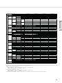
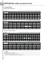
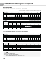
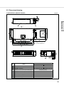
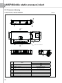
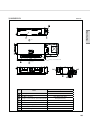
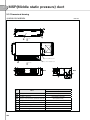
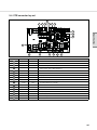
MSP (Middle static pressure) duct
Console
Ceiling
Neo forte
Outdoor units
Products
+++ Installation
Electric specifications
Wiring works
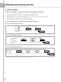
Refrigerant piping works
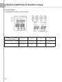
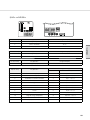
Option switches & function keys
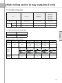
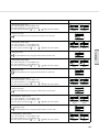
High ceiling option (4Way cassette S only)
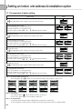
Setting an indoor unit address & installation option
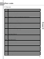
Error code
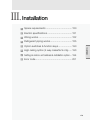
Installation
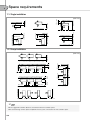
Space requirements
Specifications
5
3URGXFWV
6
Products
+ Products
Nomenclature ..................................................8
Line-up ..........................................................12
Accessory......................................................14
7
1
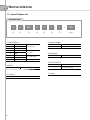
Nomenclature
1-1. Indoor/Outdoor unit
Old Model Name
SH
H
H
035
100
ET
AT
VF
1E
Classification +
Slim 1 way
C
4 way
T
Mini 4 way
E
Slim
MSP
F
Ceiling
J
Console
U
Universal
000
100
Buyer
Rating Voltage
S
D
/
Cassette Type
Duct Type
Convertible Type
E
1Ø, 220~240V, 50Hz
G
3Ø, 380~415V, 50Hz
Refrigerant
X
R410A
Outdoor Unit
Classification ++
Mode
H
H/P (Heat Pump)
Inverter
S
Inverter (Residential)
Version
Capacity
x 1/10 kW (3 digits)
8
V
1-2. Indoor Unit
Products
New Model Name
AC
H
N
H
026
100
NT
DT
EF
HE
AE
Classification ,
AC
/
000
100
Buyer
Rating Voltage
CAC
E
1Ø, 220~240V, 50Hz
G
3Ø, 380~415V, 50Hz
Classification ,,
N
Mode & Refrigerant
Indoor
H
Heat Pump (R410A)
Capacity
x 1/10 kW (3 digits)
Product Notation ,
1
1 way
2
2 way
N
Mini 4 way
4
4 way
Version
A
Basic model (Not NASA)
B
Derivation model (NASA)
Cassette Type
Product Notation ,,
F
Flagship
P
Premium
D
Deluxe
S
Standard
Indoor
9
1
Nomenclature
1-2. Indoor Unit
Old Model Name
NS
H
100
100
4H
DT
XT
EF
AE
CAC (Single)
Capacity
x 1/10 kW (3 digits)
Buyer
1
Slim 1 way
2
2 way
M
Mini 4 way
4
4 way
H
HSP duct
S
MSP duct
L
Slim duct(LSP)
C
Ceiling
J
Console
N
Neo forte
Z
Flagship (Heat Pump)
P
Premium (Heat Pump)
D
Deluxe (Heat Pump)
H
Heat Pump
Refrigerant
Product Notation
10
000
100
Mode
Classification
NS
/
X
R410A
Cassette Type
Rating Voltage
E
1Ø, 220~240V, 50Hz
G
3Ø, 380~415V, 50Hz
Duct Type
Convertible Type
Version
A~Z
Wall Mounted Type
Export
1-3. Outdoor Unit
Products
New Model Name
RC
H
100
100
DH
HT
XT
EF
AE
000
100
Buyer
Refrigerant
Classification
RC
/
CAC (Single)
Capacity
X
R410A
Rating Voltage
x 1/10 kW (3 digits)
E
1Ø, 220~240V, 50Hz
G
3Ø, 380~415V, 50Hz
Product Notation
P
Inverter Premium
D
Inverter Deluxe
Z
Flagship
S
Standard
Version
A~Z
Export
Mode
C
Cooling Only
H
Heat Pump
11
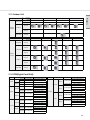
2
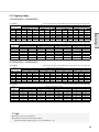
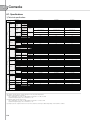
Line-up
2-1. Indoor Unit
Capacity
Type
Slim
1 way
cassette
Mini
4 way
cassette
4 way
cassette S
(Deluxe)
4 way
cassette S
(Premium)
4 way
cassette S
(Flagship)
Slim duct
MSP duct
Console
Ceiling
Neo forte
12
2.6kW
3.5kW
5.2kW
6.0kW
7.0/
7.1kW
9.0kW
10.0kW
12.5kW
14.0kW
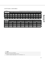
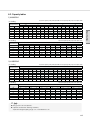
2-2. Outdoor Unit
Type
Capacity
2.6kW
3.5kW
5.2kW
6.0kW
Products
Type
1Phase
3Phase
Premium
1Phase
Smart
Inverter
Deluxe
3Phase
Standard
Type
1Phase
Type
Flagship
Capacity
7.0/7.1kW
9.0kW
10.0kW
12.5kW
14.0kW
1Phase
1Phase
Premium
3Phase
Smart
Inverter
1Phase
Deluxe
3Phase
Standard
1Phase
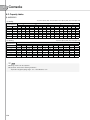
2-3. DPM(Digital Pack Multi)
Capacity
Smart Inverter
Outdoor Unit
Indoor Unit
1Phase RC071PHXEA ACN035NDEHA/EU x 2
Premium
3Phase
7.1kW
1Phase RC071DHXEA ACN035NDEHA/EU x 2
Deluxe
3Phase
ACN052NDEHA/EU x 2
1Phase RC100PHXEA
ACN035NDEHA/EU x 3
Premium
ACN052NDEHA/EU x 2
3Phase RC100PHXGA
ACN035NDEHA/EU x 3
10.0kW
ACN052NDEHA/EU x 2
1Phase RC100DHXEA
ACN035NDEHA/EU x 3
Deluxe
ACN052NDEHA/EU x 2
3Phase RC100DHXGA
ACN035NDEHA/EU x 3
ACN060NDEHA/EU x 2
1Phase RC125PHXEA
ACN052NDEHA/EU x 3
Premium
ACN060NDEHA/EU x 2
3Phase RC125PHXGA
ACN052NDEHA/EU x 3
12.5kW
ACN060NDEHA/EU x 2
1Phase RC125DHXEB
ACN052NDEHA/EU x 3
Deluxe
ACN060NDEHA/EU x 2
3Phase RC125DHXGA
ACN052NDEHA/EU x 3
Capacity
Smart Inverter
1Phase
Outdoor Unit
RC140PHXEA
RC140PHXEA
Premium
3Phase
RC140PHXGA
RC140PHXGA
14.0kW
1Phase
RC140DHXEB
RC140DHXEB
Deluxe
3Phase
RC140DHXGA
RC140DHXGA
Indoor Unit
ACN071NDEHA/EU x 2
ACN052NDEHA/EU x 3
ACN035NDEHA/EU x 4
NS0714DXEA x 2
ACN071NDEHA/EU x 2
ACN052NDEHA/EU x 3
ACN035NDEHA/EU x 4
NS0714DXEA x 2
ACN071NDEHA/EU x 2
ACN052NDEHA/EU x 3
ACN035NDEHA/EU x 4
NS0714DXEA x 2
ACN071NDEHA/EU x 2
ACN052NDEHA/EU x 3
ACN035NDEHA/EU x 4
NS0714DXEA x 2
13
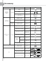
3
Accessory
Classification
Integrated
management
system
Controller
Product
Model
DMS 2
MIM-D00A
S-NET 3
MST-P3P
S-NET mini
(Touch Panel Controller)
MST-S3W
Centralized controller
(On/Off Controller)
MCM-A202D
Function controller
MCM-A100
Centralized controller
interface module
MIM-B13D
Wireless remote controller
MR-DH00
Wired remote controller
MWR-WE10
Wired remote controller
MWR-WH00
MWR-WH01
Wired remote controller
MWR-SH00
Controller
Centralized
control system
Interface
module
Individual control
system
Controller
Wireless
signal
receiver kit
Guest room management system
Wireless signal
receiver
MRK-A00
Receiver wire
MRK-10A
External Temp. Sensor
MRW-TA
External contact
interface module
MIM-B14
2 indoor units connection
MXJ-2D2509K
3 indoor units connection
MXJ-3D2509K
4 indoor units connection
MXJ-4D2509K
Joint
14
Image
Classification
Model
Slim 1 way cassette
PSSMA
Slim 1 way cassette
PC1NUPMA
Mini 4 way cassette
(Waffle Pattern)
PC4SUSMA
Mini 4 way cassette
PMSMA
4 way cassette S
(Waffle Pattern)
PC4NUSKA
4 way cassette S
(Waffle Pattern, Black)
PC4NBSKA
4 way cassette S
(Classic Pattern)
PC4NUSKE
Motion Detect Sensor
Kit
Mini 4 way cassette
MCR-SMA
S-Plasma ion Kit
4way cassette S
Mini 4 way cassette
MSD-CAN1
Slim duct
MDP-E075SEE3
MSP duct
(1,150mm x 260(320)mm x 480mm)
MDP-M075SGU1
MSP duct
(1,200mm x 360mm x 650mm)
MDP-M075SGU2
MSP duct
(900mm x 260mm x 480mm)
MDP-M075SGU3
Front Panel
Image
Products
Product
Drain Pump
15
6SHFL¿FDWLRQV
16
++ Specifications
Slim 1 way cassette ...........................................19
Specifications
Mini 4 way cassette............................................27
4 way cassette S................................................47
Slim duct ............................................................83
MSP (Middle static pressure) duct ......................95
Console............................................................117
Ceiling ..............................................................129
Neo forte ..........................................................139
Outdoor units ...................................................151
17
6SHFL¿FDWLRQV
18
Specifications
1 Slim 1 way cassette
1-1. Specifications....................................................................... 20
1-2. Capacity tables .................................................................... 21
1-3. Dimensional drawing ............................................................ 22
1-4. PCB connector lay-out......................................................... 23
1-5. Electrical wiring diagram ....................................................... 24
1-6. Sound pressure level ........................................................... 25
1-7. Temperature and air flow distribution..................................... 26
19
1
Slim 1 way cassette
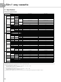
1-1. Specifications
1) Technical specifications
Model Name
Indoor Unit
Outdoor Unit
Mode
Capacity
Capacity
(Nominal)
Power Input
(Nominal)
Power
System
Current Input
(Nominal)
COP
Cooling *1)
(Min / Std / Max)
Heating *2)
(Min / Std / Max)
Cooling *1)
(Min / Std / Max)
Heating *2)
(Min / Std / Max)
Cooling *1)
(Min / Std / Max)
Heating *2)
(Min / Std / Max)
Nominal Cooling
Nominal Heating
Energy Grade Cooling / Heating
Option Code
Piping
Connections
Refrigerant
Liquid Pipe
Gas Pipe
Max. Length
Installation
Limitation
Max. Height
Type
Control Method
Factory Charging
Power Supply
Type
Motor
Output
Number of Unit
Fan
Drain
Indoor Unit
Sound
External
Dimension
Panel Size
Additional
Accessories
Air Flow Rate
High / Mid / Low
External Static
Min / Std / Max
Pressure
Drain Pipe
Sound
High / Mid / Low
Pressure *3)
Net Weight
Shipping Weight
Net Dimensions (WxHxD)
Shipping Dimensions (WxHxD)
Panel model
Panel Net Weight
Shipping Weight
Net Dimensions (W×H×D)
Shipping Dimensions (W×H×D)
Drain pump
Max. Lifting
Drain pump
Height /
Displacement
Air Filter
Power Supply
Outdoor Unit
Compressor
Fan
Sound
External
Dimension
Operating
Temp. Range
Type
Model
Oil
Type
Initial Charge
Air Flow Rate
Cooling / Heating
Sound
Cooling / Heating
Pressure *3)
Net Weight
Shipping Weight
Net Dimensions (WxHxD)
Shipping Dimensions (WxHxD)
Cooling
Heating
kW
Btu/h
kW
Btu/h
NS0261DXEA
RC026DHXEA
Heat Pump
1.00 / 2.60 / 3.50
3,400 / 8,900 / 11,900
1.00 / 3.30 / 4.60
3,400 / 11,300 / 15,700
NS0351DXEA
RC035DHXEA
Heat Pump
1.00 / 3.50 / 4.10
3,400 / 11,900 / 14,000
1.00 / 4.00 / 4.80
3,400 / 13,600 / 16,400
0.25 / 0.70 / 1.12
0.25 / 1.14 / 1.42
kW
0.21 / 0.91 / 1.30
0.21 / 1.16 / 1.39
1.60 / 3.30 / 5.20
1.60 / 5.30 / 6.60
A
1.40 / 5.30 / 6.40
1.40 / 5.50 / 6.80
Ø, mm(inch)
Ø, mm(inch)
m
m
kg
Ø, #, V, Hz
W
EA
CMM
CFM
mmAq
Pa
Ø, mm
3.71
3.63
A/A
017057-1860F8-271A23-370010
6.35 (1/4)
9.52 (3/8)
20.0
15.0
R410A
EEV
0.95
1, 2, 220~240, 50
Cross flow
56
1
8.0 / 7.0 / 6.0
283 / 247 / 212
VP20 (OD 26,ID 20)
3.07
3.45
B/B
017057-17624D-272328-370010
6.35 (1/4)
9.52 (3/8)
20.0
15.0
R410A
EEV
0.95
1, 2, 220~240, 50
Cross flow
60
1
8.5 / 7.5 / 6.5
300 / 265 / 230
VP20 (OD 26,ID 20)
dB(A)
30 /27 / 25
34 / 31.5 / 28
kg
kg
mm
mm
kg
kg
mm
mm
-
9.0
11.0
970 x 135 x 410
1,164 x 212 x 478
PSSMA / PC1NUPMA
3.1
4.5
1,180 x 25 x 460
1,259 x 144 x 539
Built-in
9.0
11.0
970 x 135 x 410
1,164 x 212 x 478
PSSMA / PC1NUPMA
3.1
4.5
1,180 x 25 x 460
1,259 x 144 x 539
Built-in
mm / liter/h
750 / 24
750 / 24
Ø, #, V, Hz
cc
CMM
CFM
Long life filter
1, 2, 220~240, 50
Single BLDC Rotary
UG4C090LUDJR
POE
320
29 / 29
1,024 / 1,024
Long life filter
1, 2, 220~240, 50
Single BLDC Rotary
UG4C090LUDJR
POE
320
30 / 30
1,060 / 1,060
dB(A)
46/47
47/48
kg
kg
mm
mm
°C
°C
33.0
37.0
790 x 548 x 285
926 x 655 x 382
-10 ~ 46
-15 ~ 24
33.0
37.0
790 x 548 x 285
926 x 655 x 382
-10 ~ 46
-15 ~ 24
*Specifications may be subject to change without prior notice for product improvement.
*1) Nominal cooling capacities are based on;
- Indoor temperature : 27°C DB, 19°C WB / Outdoor temperature : 35°C DB, 24°C WB
- Equivalent refrigerant piping : 5m, Level differences : 0m
*2) Norminal heating capacities are based on;
- Indoor temperature : 20°C DB, 15°C WB / Outdoor temperature : 7°C DB, 6°C WB
- Equivalent refrigerant piping : 5m, Level differences : 0m
*3) Sound pressure was acquired in an anechoic room. Thus actual noise level may be different depending on the installation conditions.
20
1-2. Capacity tables
1) RC026DHXEA + NS0261DXEA
(1) Cooling
TC(Total Capacity, kW), SHC(Sensible Heat Capacity, kW), PI(Power Input, kW)
Indoor
Temperature(°C)
DB
20
22
25
27
30
32
TC
2.84
2.91
2.99
3.06
3.13
3.21
PI
0.40
0.41
0.42
0.43
0.44
0.45
TC
3.41
3.50
3.58
3.67
3.76
3.85
Outdoor Temperature (°C, DB)
21
35
SHC
PI
TC
SHC
2.56
0.86
2.42
1.81
2.62
0.89
2.48
1.86
2.69
0.91
2.54
1.90
2.75
0.93
2.60
1.95
2.82
0.95
2.66
2.00
2.89
0.98
2.73
2.04
(2) Heating
PI
0.65
0.66
0.68
0.70
0.71
0.73
TC
2.65
2.71
2.78
2.85
2.92
2.99
46
SHC
1.99
2.04
2.09
2.14
2.19
2.24
PI
1.21
1.24
1.27
1.30
1.33
1.36
TC(Total Capacity, kW), PI(Power Input, kW)
Indoor
Temperature(°C)
DB
16
18
20
21
22
24
-15
TC
2.36
2.33
2.31
2.29
2.26
2.24
PI
1.00
0.99
0.98
0.97
0.96
0.95
TC
2.77
2.75
2.72
2.69
2.67
2.64
Outdoor Temperature (°C, DB)
-10
7
PI
TC
1.09
3.37
1.08
3.33
1.07
3.30
1.06
3.27
1.05
3.23
1.04
3.20
24
PI
0.93
0.92
0.91
0.90
0.89
0.88
TC
3.59
3.56
3.52
3.48
3.45
3.42
PI
0.98
0.97
0.96
0.95
0.94
0.93
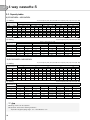
2) RC035DHXEA + NS0351DXEA
(1) Cooling
TC(Total Capacity, kW), SHC(Sensible Heat Capacity, kW), PI(Power Input, kW)
Indoor
Temperature(°C)
WB
14
16
18
19
22
24
DB
20
22
25
27
30
32
TC
3.46
3.54
3.63
3.72
3.81
3.90
-10
SHC
2.59
2.66
2.72
2.79
2.86
2.93
PI
0.75
0.77
0.79
0.81
0.83
0.85
TC
3.86
3.95
4.05
4.15
4.25
4.35
Outdoor Temperature (°C, DB)
21
35
SHC
PI
TC
SHC
2.89
1.08
3.25
2.44
2.96
1.10
3.33
2.50
3.04
1.13
3.42
2.56
3.11
1.16
3.50
2.63
3.19
1.19
3.58
2.69
3.26
1.22
3.67
2.75
(2) Heating
TC
2.79
2.86
2.93
3.00
3.07
3.15
46
SHC
2.09
2.14
2.20
2.25
2.30
2.36
PI
1.21
1.24
1.27
1.30
1.33
1.36
TC(Total Capacity, kW), PI(Power Input, kW)
Indoor
Temperature(°C)
DB
16
18
20
21
22
24
PI
1.06
1.09
1.11
1.14
1.17
1.20
-15
TC
2.56
2.54
2.51
2.48
2.46
2.44
PI
1.30
1.28
1.27
1.26
1.24
1.23
TC
3.38
3.34
3.31
3.28
3.24
3.21
Outdoor Temperature (°C, DB)
-10
7
PI
TC
1.41
4.08
1.39
4.04
1.38
4.00
1.37
3.96
1.35
3.92
1.34
3.88
24
PI
1.18
1.17
1.16
1.15
1.14
1.13
TC
4.36
4.31
4.27
4.23
4.19
4.14
PI
1.26
1.25
1.24
1.23
1.22
1.20
; Note
X Ratings shown are net capacities.
X Capacities are based on following conditions;
- Equivalent refrigerant piping length : 5m / Level difference : 0m.
21
Specifications
WB
14
16
18
19
22
24
-10
SHC
2.13
2.19
2.24
2.30
2.35
2.41
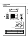
1
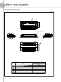
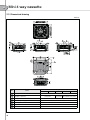
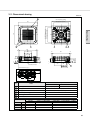
Slim 1 way cassette
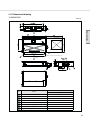
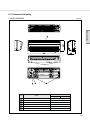
1-3. Dimensional drawing
Unit:mm
4
Suspension bolts(M8~M10) X 4EA
3
2
1
6
5
No.
Name
1
Liquid pipe connection
Gas pipe connection
Drain pipe connection
Conduit for power supply & communication wiring
Air inlet grille
Air outlet louver
2
3
4
5
6
22
Description
2.6kW
3.5kW
Ø6.35mm (1/4") Flare
Ø9.52mm (3/8") Flare
VP20 (OD26, ID20)
-
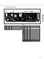
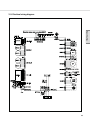
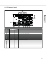
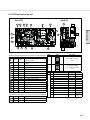
1-4. PCB connector lay-out
Specifications
Ê AC
No.
6
7
8
9
Ê DC
CN #
CN74
CN75
CN73
CN71
Color
WHT
BLK
WHT
BLU
Function
Drain Pump
Ventilator
Fan Motor
AC POWER Input
No.
CN #
Color
1
CN61
RED
2
CN62
BLU
3
4
5
10
11
12
13
14
15
16
17
18
19
CN60
CN10
CN44
CN32
CN45
CN91
CN81
CN31
CN33
CN63
CN83
CN51
CN42
WHT
BLK
BLU
WHT
YEL
WHT
RED
RED
BLU
BLU
RED
BLK
WHT
20
CN41
WHT
Function
Sliding Panel2
(Option : Sliding Panel)
Sliding Panel1
(Option : Sliding Panel)
Louver
Micom-Download
Hall-IC(RPM Feedback)
DC12V
SPI
Panel Display
Error Check, Oper. Check
COM1
COM2
EEV(Only for DVM)
External Control(On/Off)
Float switch sensor
EVA OUT Temp. sensor
Indoor Unit Temp. sensor
(Room,EVA IN)
23
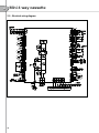
1
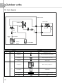
Slim 1 way cassette
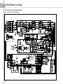
1-5. Electrical wiring diagram
(Sliding panel)
24
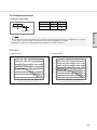
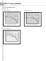
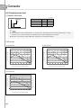
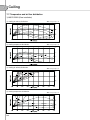
1-6. Sound pressure level
1) Operation sound level
Unit : dB(A)
1m
1m
Model
High
Low
NS0261DXEA
30
25
NS0351DXEA
34
28
Microphone
Specifications
; Note
X These operation values were obtained in an anechoic room. Sound pressure level will vary depending on a range of
factors such as the construction of the particular room where the equipment is installed.
X Operation sound level may differ depending on operation and ambient conditions.
INDOOR UNITS
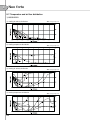
2) NC curves
(1) NS0261DXEA
(2) NS0351DXEA
45
55
50
40
35
30
0%
*+)*
0%
25
.19
0%
20
0%
15
45
Sound pressure level (dB)
Sound pressure level (dB)
0%
0%
40
0%
35
*+)*
0%
30
0%
25
.19
0%
20
0%
15
0%
10
0%
10
5
5
63
125
250
500
1000
2000
4000
Octave band center frequency(Hz)
8000
63
125
250
500
1000
2000
4000
8000
Octave band center frequency(Hz)
25
1
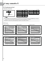
Slim 1 way cassette
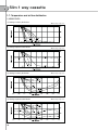
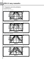
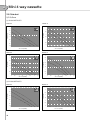
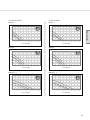
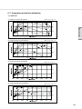
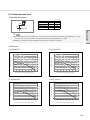
1-7. Temperature and air flow distribution
1) NS0351DXEA
(1) Cooling air velocity distribution
(2) Cooling temperature distribution
(3) Heating air velocity distribution
(4) Heating temperature distribution
26
X Discharge angle : 60°
X Discharge angle : 60°
X Discharge angle : 60°
X Discharge angle : 60°
Specifications
2 Mini 4 way cassette
INDOOR UNITS
2-1. Specifications....................................................................... 28
2-2. Capacity tables .................................................................... 29
2-3. Dimensional drawing ............................................................ 32
2-4. PCB connector lay-out......................................................... 33
2-5. Electrical wiring diagram ....................................................... 34
2-6. Sound pressure level ........................................................... 35
2-7. Temperature and air flow distribution..................................... 37
2-8. Sub duct.............................................................................. 42
27
2
Mini 4 way cassette
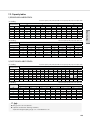
2-1. Specifications
1) Technical specifications
Model Name
Indoor Unit
Outdoor Unit
Mode
Capacity
Capacity
(Nominal)
Power Input
(Nominal)
Power
System
Current Input
(Nominal)
COP
Cooling *1)
(Min / Std / Max)
Heating *2)
(Min / Std / Max)
Cooling *1)
(Min / Std / Max)
Heating *2)
(Min / Std / Max)
Cooling *1)
(Min / Std / Max)
Heating *2)
(Min / Std / Max)
Nominal Cooling
Nominal Heating
Energy Grade Cooling / Heating
Option Code
Piping
Connections
Refrigerant
Liquid Pipe
Gas Pipe
Max. Length
Installation
Limitation
Max. Height
Type
Control Method
Factory Charging
Power Supply
Type
Motor
Output
Number of Unit
Fan
Drain
Indoor Unit
Sound
External
Dimension
Panel Size
Additional
Accessories
Air Flow Rate
High / Mid / Low
External Static
Min / Std / Max
Pressure
Drain Pipe
Sound
High / Mid / Low
Pressure *3)
Net Weight
Shipping Weight
Net Dimensions (WxHxD)
Shipping Dimensions (WxHxD)
Panel model
Panel Net Weight
Shipping Weight
Net Dimensions (W×H×D)
Shipping Dimensions (W×H×D)
Drain pump
Max. Lifting
Drain pump
Height /
Displacement
Air Filter
Power Supply
Outdoor Unit
Compressor
Fan
Sound
External
Dimension
Operating
Temp. Range
Type
Model
Oil
Type
Initial Charge
Air Flow Rate
Cooling / Heating
Sound
Cooling / Heating
Pressure *3)
Net Weight
Shipping Weight
Net Dimensions (WxHxD)
Shipping Dimensions (WxHxD)
Cooling
Heating
kW
Btu/h
kW
Btu/h
ACN026NDEHA/EU
ACN035NDEHA/EU
ACN052NDEHA/EU
ACN060NDEHA/EU
ACN071NDEHA/EU
RC026DHXEA
RC035DHXEA
RC052DHXEA
RC060DHXEA
RC071DHXEA
Heat Pump
Heat Pump
Heat Pump
Heat Pump
Heat Pump
0.99 / 2.60 / 3.50
0.99 / 3.50 / 4.20
1.30 / 5.00 / 5.90
1.80 / 5.80 / 6.50
2.00 / 6.80 / 7.50
3,400 / 8,900 / 11,900 3,400 / 11,900 / 14,300 4,400 / 17,100 / 20,100 6,100 / 19,800 / 22,200 6,800 / 23,200 / 25,600
0.98 / 3.30 / 4.60
0.98 / 4.00 / 5.00
1.30 / 5.50 / 7.50
1.60 / 7.00 / 9.00
1.60 / 7.50 / 10.00
3,300 / 11,300 / 15,700 3,300 / 13,600 / 17,100 4,400 / 18,800 / 25,600 5,500 / 23,900 / 30,700 5,500 / 25,600 / 34,100
0.23 / 0.73 / 1.13
0.24 / 1.09 / 1.45
0.31 / 1.56 / 2.10
0.38 / 1.81 / 2.60
0.18 / 0.90 / 1.40
0.18 / 1.11 / 1.40
0.35 / 1.53 / 2.40
0.35 / 2.18 / 3.60
0.35 / 2.34 / 3.80
1.60 / 3.70 / 5.50
1.60 / 5.60 / 6.80
2.60 / 7.20 / 9.50
1.90 / 8.30 / 11.50
1.90 / 9.70 / 11.50
1.20 / 4.60 / 6.60
1.20 / 5.70 / 6.70
2.90 / 7.00 / 11.00
1.70 / 10.00 / 17.30
1.70 / 10.70 / 17.60
A
-
3.56
3.21
3.21
3.21
3.21
3.67
3.61
3.61
3.21
3.21
A/A
A/A
A/A
A/C
A/C
015077-1660F8
015077-166219
015077-17625D
015077-18626E
015077-166381-271A21-370000
-272328-370000
-273437-370040
-273C46-370040
274750-370040
Ø, mm(inch)
6.35 (1/4)
6.35 (1/4)
6.35 (1/4)
6.35 (1/4)
6.35 (1/4)
Ø, mm(inch)
9.52 (3/8)
9.52 (3/8)
12.70 (1/2)
15.88 (5/8)
15.88 (5/8)
m
20.0
20.0
30.0
50.0
50.0
m
15.0
15.0
20.0
30.0
30.0
R410A
R410A
R410A
R410A
R410A
EEV
EEV
EEV
EEV
EEV
kg
0.95
0.95
1.40
1.80
1.80
Ø, #, V, Hz
1, 2, 220~240, 50
1, 2, 220~240, 50
1, 2, 220~240, 50
1, 2, 220~240, 50
1, 2, 220~240, 50
Turbo Fan/BLDC
Turbo Fan/BLDC
Turbo Fan/BLDC
Turbo Fan/BLDC
Turbo Fan/BLDC
W
EA
1
1
1
1
1
CMM
6.9/8.2/9.9
7.4/9.0/10.7
9.0/10.7/12.4
9.5/11.1/12.8
10.7/12.0/13.7
CFM
256.63 / 303.22 / 361.47 274.98 / 330.4 / 391.83 330.4 / 391.83 / 447.25 346.64 / 403.12 / 463.48 391.83 / 447.25 / 505.84
mmAq
Pa
Ø, mm
VP25 (OD 32, ID 25)
VP25 (OD 32, ID 25)
VP25 (OD 32, ID 25)
VP25 (OD 32, ID 25)
VP25 (OD 32, ID 25)
dB(A)
34/31/27
36/33/29
39/37/34
41/38/34
42/40/36
kg
kg
mm
mm
kg
kg
mm
mm
-
11 .0
13 .0
575 x 250 x 575
623 x 298 x 653
PC4SUSMA
2.7
4.2
670 x 45 x 670
714 x 106 x 724
Built-in
11 .0
13 .0
575 x 250 x 575
623 x 298 x 653
PC4SUSMA
2.7
4.2
670 x 45 x 670
714 x 106 x 724
Built-in
11 .7
13 .7
575 x 250 x 575
623 x 298 x 653
PC4SUSMA
2.7
4.2
670 x 45 x 670
714 x 106 x 724
Built-in
12.0
14.0
575 x 250 x 575
623 x 298 x 653
PC4SUSMA
2.7
4.2
670 x 45 x 670
714 x 106 x 724
Built-in
12.0
14.0
575 x 250 x 575
623 x 298 x 653
PC4SUSMA
2.7
4.2
670 x 45 x 670
714 x 106 x 724
Built-in
mm / liter/h
750 / 24
750 / 24
750 / 24
750 / 24
750 / 24
Ø, #, V, Hz
cc
CMM
CFM
Long life filter
1, 2, 220~240, 50
Single BLDC Rotary
G4C090LUDJR
POE
320
28.6/28.6
1010/1010
Long life filter
1, 2, 220~240, 50
Single BLDC Rotary
G4C090LUDJR
POE
320
30.2/30.2
1067/1067
Long life filter
1, 2, 220~240, 50
Twin BLDC Rotary
UG4T150FUDJQ
POE
650
35.7/33.4
1261/1180
Long life filter
1, 2, 220~240, 50
Twin BLDC Rotary
UG4T200FUAE4
POE
650
46.0/44.1
1625/1557
Long life filter
1, 2, 220~240, 50
Twin BLDC Rotary
UG4T200FUAE4
POE
650
50.0/48.0
1766/1695
dB(A)
46/47
47/48
48/49
49/50
49/51
kg
kg
mm
mm
°C
°C
33.0
37.0
790 x 548 x 285
926 x 655 x 382
-10 ~ 46
-15 ~ 24
33.0
37.0
790 x 548 x 285
926 x 655 x 382
-10 ~ 46
-15 ~ 24
38.5
42.5
790 x 548 x 285
926 x 655 x 382
-15 ~ 46
-15 ~ 24
55.0
59.0
880 x 798 x 310
1,023 x 891 x 413
-15 ~ 46
-20 ~ 24
55.0
59.0
880 x 798 x 310
1,023 x 891 x 413
-15 ~ 50
-20 ~ 24
*Specifications may be subject to change without prior notice for product improvement.
*1) Nominal cooling capacities are based on;
- Indoor temperature : 27°C DB, 19°C WB / Outdoor temperature : 35°C DB, 24°C WB
- Equivalent refrigerant piping : 5m, Level differences : 0m
*2) Norminal heating capacities are based on;
- Indoor temperature : 20°C DB, 15°C WB / Outdoor temperature : 7°C DB, 6°C WB
- Equivalent refrigerant piping : 5m, Level differences : 0m
*3) Sound pressure was acquired in an anechoic room. Thus actual noise level may be different depending on the installation conditions.
28
0.39 / 2.12 / 2.60
kW
2-2. Capacity tables
1) RC026DHXEA + ACN026NDEHA
(1) Cooling
TC(Total Capacity, kW), SHC(Sensible Heat Capacity, kW), PI(Power Input, kW)
-10
SHC
2.1
2.2
2.2
2.3
2.4
2.4
TC
2.7
2.7
2.8
2.9
2.9
3.0
PI
0.6
0.6
0.6
0.6
0.6
0.6
TC
2.6
2.7
2.8
2.8
2.9
3.0
Outdoor Temperature (°C, DB)
21
35
SHC
PI
TC
SHC
2.1
0.5
2.4
1.9
2.1
0.5
2.4
1.9
2.2
0.5
2.5
2.0
2.3
0.5
2.6
2.0
2.3
0.5
2.6
2.1
2.4
0.5
2.7
2.1
(2) Heating
TC
2.5
2.5
2.6
2.7
2.7
2.8
46
SHC
2.0
2.0
2.1
2.1
2.2
2.2
PI
1.2
1.3
1.3
1.3
1.4
1.4
TC(Total Capacity, kW), PI(Power Input, kW)
Outdoor Temperature (°C, DB)
-15
-10
TC
2.3
2.3
2.3
2.2
2.2
2.2
PI
1.0
1.0
1.0
1.0
1.0
1.0
TC
2.7
2.6
2.6
2.6
2.5
2.5
7
PI
1.1
1.1
1.1
1.1
1.1
1.1
24
TC
3.4
3.3
3.3
3.3
3.2
3.2
PI
0.9
0.9
0.9
0.9
0.9
0.9
TC
4.7
4.7
4.7
4.6
4.6
4.5
PI
1.3
1.3
1.3
1.3
1.3
1.3
INDOOR UNITS
Indoor
Temperature(°C)
DB
16
18
20
21
22
24
PI
0.7
0.7
0.7
0.7
0.7
0.8
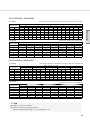
2) RC035DHXEA + ACN035NDEHA
(1) Cooling
Indoor
Temperature(°C)
WB
DB
14
20
16
22
18
25
19
27
22
30
24
32
TC(Total Capacity, kW), SHC(Sensible Heat Capacity, kW), PI(Power Input, kW)
-10
SHC
2.8
2.9
3.0
3.0
3.1
3.2
TC
3.5
3.6
3.7
3.8
3.9
4.0
PI
0.9
0.9
0.9
0.9
1.0
1.0
TC
3.4
3.5
3.6
3.6
3.7
3.8
Outdoor Temperature (°C, DB)
21
35
SHC
PI
TC
SHC
2.7
0.8
3.3
2.6
2.8
0.8
3.3
2.7
2.8
0.8
3.4
2.7
2.9
0.9
3.5
2.8
3.0
0.9
3.6
2.9
3.1
0.9
3.7
2.9
(2) Heating
Indoor
Temperature(°C)
DB
16
18
20
21
22
24
PI
1.0
1.0
1.1
1.1
1.1
1.1
TC
2.5
2.5
2.6
2.7
2.7
2.8
46
SHC
2.0
2.0
2.1
2.1
2.2
2.2
PI
1.2
1.3
1.3
1.3
1.4
1.4
TC(Total Capacity, kW), PI(Power Input, kW)
Outdoor Temperature (°C, DB)
-15
TC
2.5
2.5
2.4
2.4
2.4
2.4
-10
PI
1.1
1.1
1.1
1.0
1.0
1.0
TC
2.9
2.9
2.8
2.8
2.8
2.7
7
PI
1.2
1.1
1.1
1.1
1.1
1.1
TC
4.1
4.0
4.0
4.0
3.9
3.9
Specifications
Indoor
Temperature(°C)
WB
DB
14
20
16
22
18
25
19
27
22
30
24
32
24
PI
1.1
1.1
1.1
1.1
1.1
1.1
TC
5.3
5.3
5.2
5.1
5.1
5.0
PI
1.3
1.3
1.3
1.3
1.3
1.3
; Note
X Ratings shown are net capacities.
X Capacities are based on following conditions;
- Equivalent refrigerant piping length : 5m / Level difference : 0m.
29
2
Mini 4 way cassette
2-2. Capacity tables
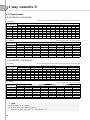
3) RC052DHXEA + ACN052NDEHA
(1) Cooling
Indoor
Temperature(°C)
WB
DB
14
20
16
22
18
25
19
27
22
30
24
32
TC(Total Capacity, kW), SHC(Sensible Heat Capacity, kW), PI(Power Input, kW)
-10
SHC
3.8
3.9
4.0
4.1
4.2
4.3
TC
4.8
4.9
5.0
5.1
5.3
5.4
PI
1.2
1.2
1.2
1.3
1.3
1.3
TC
4.8
4.9
5.0
5.1
5.2
5.4
Outdoor Temperature (°C, DB)
21
35
SHC
PI
TC
SHC
3.8
1.1
4.6
3.7
3.9
1.1
4.8
3.8
4.0
1.1
4.9
3.9
4.1
1.2
5.0
4.0
4.2
1.2
5.1
4.1
4.3
1.2
5.2
4.2
(2) Heating
Indoor
Temperature(°C)
DB
16
18
20
21
22
24
PI
1.5
1.5
1.5
1.6
1.6
1.6
TC
3.0
3.0
3.1
3.2
3.3
3.4
46
SHC
2.4
2.4
2.5
2.6
2.6
2.7
PI
1.2
1.2
1.3
1.3
1.3
1.4
TC(Total Capacity, kW), PI(Power Input, kW)
Outdoor Temperature (°C, DB)
-15
-10
TC
4.3
4.2
4.2
4.2
4.1
4.1
PI
1.8
1.8
1.8
1.8
1.8
1.7
TC
4.6
4.5
4.5
4.5
4.4
4.4
7
PI
2.0
1.9
1.9
1.9
1.9
1.9
24
TC
5.6
5.6
5.5
5.4
5.4
5.3
PI
1.6
1.5
1.5
1.5
1.5
1.5
TC
6.8
6.8
6.7
6.6
6.6
6.5
PI
1.7
1.7
1.7
1.7
1.7
1.6
4) RC060DHXEA + ACN060NDEHA
(1) Cooling
Indoor
Temperature(°C)
WB
DB
14
20
16
22
18
25
19
27
22
30
24
32
TC(Total Capacity, kW), SHC(Sensible Heat Capacity, kW), PI(Power Input, kW)
-10
SHC
4.7
4.8
4.9
5.0
5.2
5.3
TC
5.9
6.0
6.1
6.3
6.5
6.6
PI
1.5
1.5
1.6
1.6
1.6
1.7
TC
6.5
6.6
6.8
7.0
7.1
7.3
Outdoor Temperature (°C, DB)
21
35
SHC
PI
TC
SHC
5.2
1.5
5.4
4.3
5.3
1.6
5.5
4.4
5.4
1.6
5.7
4.5
5.6
1.7
5.8
4.6
5.7
1.7
5.9
4.8
5.8
1.7
6.1
4.9
(2) Heating
Indoor
Temperature(°C)
DB
16
18
20
21
22
24
TC
5.5
5.7
5.8
6.0
6.1
6.2
46
SHC
4.4
4.5
4.6
4.8
4.9
5.0
PI
2.9
3.0
3.0
3.1
3.2
3.3
TC(Total Capacity, kW), PI(Power Input, kW)
Outdoor Temperature (°C, DB)
-15
TC
4.8
4.7
4.7
4.6
4.6
4.5
-10
PI
2.4
2.4
2.4
2.4
2.4
2.3
TC
6.1
6.1
6.0
5.9
5.9
5.8
7
PI
2.9
2.8
2.8
2.8
2.7
2.7
; Note
X Ratings shown are net capacities.
X Capacities are based on following conditions;
- Equivalent refrigerant piping length : 5m / Level difference : 0m.
30
PI
1.7
1.7
1.8
1.8
1.9
1.9
TC
7.1
7.1
7.0
6.9
6.9
6.8
24
PI
2.2
2.2
2.2
2.2
2.1
2.1
TC
8.6
8.5
8.4
8.3
8.2
8.2
PI
2.9
2.8
2.8
2.8
2.7
2.7
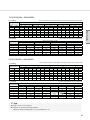
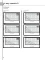
5) RC071DHXEA + ACN071NDEHA
(1) Cooling
TC(Total Capacity, kW), SHC(Sensible Heat Capacity, kW), PI(Power Input, kW)
-10
SHC
5.0
5.1
5.2
5.4
5.5
5.6
TC
6.2
6.4
6.5
6.7
6.9
7.0
PI
1.5
1.5
1.6
1.6
1.6
1.7
TC
6.8
7.0
7.1
7.3
7.5
7.7
Outdoor Temperature (°C, DB)
21
35
SHC
PI
TC
SHC
5.4
1.5
6.3
5.1
5.6
1.5
6.5
5.2
5.7
1.6
6.6
5.3
5.8
1.6
6.8
5.4
6.0
1.6
7.0
5.6
6.1
1.7
7.1
5.7
(2) Heating
Indoor
Temperature(°C)
DB
16
18
20
21
22
24
PI
2.0
2.0
2.1
2.1
2.2
2.2
TC
4.7
4.9
5.0
5.1
5.2
5.3
46
SHC
3.8
3.9
4.0
4.1
4.2
4.3
PI
2.6
2.7
2.7
2.8
2.9
2.9
TC(Total Capacity, kW), PI(Power Input, kW)
Outdoor Temperature (°C, DB)
-15
TC
5.0
4.9
4.9
4.9
4.8
4.8
-10
PI
2.7
2.6
2.6
2.6
2.5
2.5
TC
5.9
5.9
5.8
5.7
5.7
5.6
7
PI
3.0
2.9
2.9
2.9
2.8
2.8
TC
7.7
7.6
7.5
7.4
7.4
7.3
24
PI
2.4
2.4
2.3
2.3
2.3
2.3
TC
7.2
7.2
7.1
7.0
7.0
6.9
PI
1.8
1.8
1.8
1.8
1.8
1.7
; Note
X Ratings shown are net capacities.
X Capacities are based on following conditions;
- Equivalent refrigerant piping length : 5m / Level difference : 0m.
31
Specifications
Indoor
Temperature(°C)
WB
DB
14
20
16
22
18
25
19
27
22
30
24
32
2
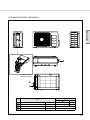
Mini 4 way cassette
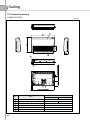
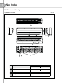
2-3. Dimensional drawing
Unit:mm
1
3
2
4
7
5
6
No.
1
Liquid pipe connection
2
Gas pipe connection
3
Drain pipe connection
Conduit for power supply & communication wiring
Air inlet grille
Air outlet louver
Fresh air intake
4
5
6
7
32
Name
Description
2.6kW
3.5kW
5.2kW
6.0kW
7.1kW
Ø6.35mm (1/4") Flare
Ø9.52mm
Ø12.7mm
Ø15.88mm (5/8") Flare
(3/8") Flare
(1/2") Flare
VP25 (OD32, ID25)
Ø100
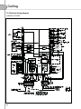
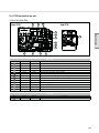
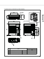
2-4. PCB connector lay-out
(a)
(b)
Specifications
Ê AC
No. CN #
TB101
1
CN102
2
CN701
3
(c)
Ê DC
Color
Black
White
White
Function
Input Power (L, N)
Earth Wire
BLDC Fan Motor
No. CN #
CN411
4
5
CN413
6
7
8
9
10
11
12
13
14
15
(a)
(b)
(c)
CN412
CN501
CN804
CN806
CN801
CN103
CN201
CN401
CN805
CN81
CN83
TB301
CN301
Color
Black
Function
Float Sensor
Eva In/Out/Discharge Temperature
Yellow
Sensor
White Indoor Room Temperature sensor
White Display
Blue Ventilator
Blue Louver 3/4
Yellow SPi(S-Plasma ion)
Yellow DC drain pump
White EEPROM
Red Human Sensor
White Louver 1/2
Red External Monitor
Red External signal (On/Off)
Black COM1/COM2 communication
Black Download
33
2
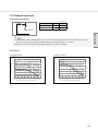
Mini 4 way cassette
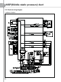
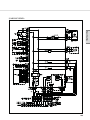
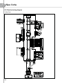
2-5 . Electrical wiring diagram
34
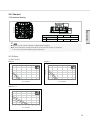
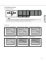
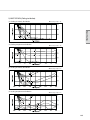
2-6. Sound pressure level
1) Operation sound level
Unit : dB(A)
1.5m
Microphone
High
Low
ACN026NDEHA/EU
34
27
ACN035NDEHA/EU
36
29
ACN052NDEHA/EU
39
34
ACN060NDEHA/EU
41
34
ACN071NDEHA/EU
42
36
Specifications
Model
; Note
X These operation values were obtained in an anechoic room. Sound pressure level will vary depending on a range of
factors such as the construction of the particular room where the equipment is installed.
X Operation sound level may differ depending on operation and ambient conditions.
2) NC curves
Sound pressure level (dB)
(2) ACN035NDEHA/EU
Sound pressure level (dB)
(1) ACN026NDEHA/EU
63
125
250
500
1000
2000
4000
Octave band center frequency(Hz)
8000
63
125
250
500
1000
2000
4000
8000
Octave band center frequency(Hz)
35
2
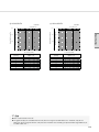
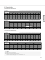
Mini 4 way cassette
2-6. Sound pressure level
2) NC curves
(3) ACN052NDEHA/EU
(4) ACN060NDEHA/EU
55
45
NC 45
40
NC 40
35
NC 35
30
NC 30
25
NC 25
20
Sound pressure level (dB)
Sound pressure level (dB)
50
NC 20
15
10
NC 15
5
63
125
250
500
1000
2000
4000
8000
Octave band center frequency(Hz)
Octave band center frequency(Hz)
Sound pressure level (dB)
(5) ACN071NDEHA/EU
63
125
250
500
1000
2000
4000
Octave band center frequency(Hz)
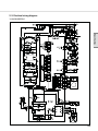
36
8000
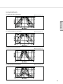
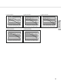
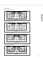
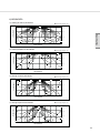
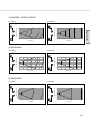
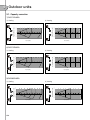
2-7. Temperature and air flow distribution
1) ACN026NDEHA/EU
(1) Cooling air velocity distribution
X Discharge angle : 41°
Specifications
(2) Cooling temperature distribution
(3) Heating air velocity distribution
(4) Heating temperature distribution
X Discharge angle : 41°
X Discharge angle : 52°
X Discharge angle : 52°
37
2
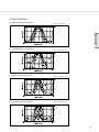
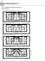
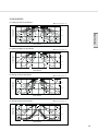
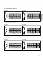
Mini 4 way cassette
2-7. Temperature and air flow distribution
2) ACN035NDEHA/EU
(1) Cooling air velocity distribution
(2) Cooling temperature distribution
(3) Heating air velocity distribution
(4) Heating temperature distribution
38
X Discharge angle : 41°
X Discharge angle : 41°
X Discharge angle : 52°
X Discharge angle : 52°
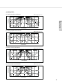
3) ACN052NDEHA/EU
(1) Cooling air velocity distribution
X Discharge angle : 41°
Specifications
(2) Cooling temperature distribution
(3) Heating air velocity distribution
(4) Heating temperature distribution
X Discharge angle : 41°
X Discharge angle : 52°
X Discharge angle : 52°
39
2
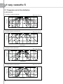
Mini 4 way cassette
2-7. Temperature and air flow distribution
4) ACN060NDEHA/EU
(1) Cooling air velocity distribution
(2) Cooling temperature distribution
(3) Heating air velocity distribution
(4) Heating temperature distribution
40
X Discharge angle : 41°
X Discharge angle : 41°
X Discharge angle : 52°
X Discharge angle : 52°
5) ACN071NDEHA/EU
(1) Cooling air velocity distribution
X Discharge angle : 41°
Specifications
(2) Cooling temperature distribution
(3) Heating air velocity distribution
(4) Heating temperature distribution
X Discharge angle : 41°
X Discharge angle : 52°
X Discharge angle : 52°
41
2
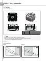
Mini 4 way cassette
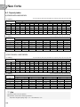
2-8. Sub duct
1) Dimensional drawing
Branch }
Sub
duc
t #2
du
ct
#3
Branch |
Sub
duc
t #1
Su
b
Branch {
Su
b
du
ct
#4
(Drain pipe connection part)
Branch ~
(Fresh Air Intake connection part)
575
A
120
B
250
120
300
Indoor Unit (Height)
A
mm
B
mm
250
575
250mm
225 (Branch }), 150 (Branch ~)
212.5 (Branch }), 137.5 (Branch ~)
; Note
X Sub duct can be used for 4 directions independently or together.
X Be sure to seal off the air outlet of the indoor unit to which the sub duct is connected.
If not, it may cause water splattering and condensation.
2) P-Q Curve
(1) ACN026NDEHA/EU
Branch |
3
3
2.5
2.5
2
2
ESP (mmAq)
ESP (mmAq)
Branch {
1.5
1
0.5
0
1
0.5
0
0.5
1
1.5
2
Air Flow (CMM)
42
1.5
2.5
3
3.5
0
0
0.5
1
1.5
2
Air Flow (CMM)
2.5
3
3.5
Branch ~
2.5
2
2
ESP (mmAq)
2.5
1.5
1
0.5
1.5
Specifications
ESP (mmAq)
Branch }
1
0.5
0
0
0
0.5
1
1.5
2
2.5
3
0
0.5
1
Air Flow (CMM)
1.5
2
2.5
3
Air Flow (CMM)
(2) ACN035NDEHA/EU
Branch {
Branch |
2.5
3.5
3
2
ESP (mmAq)
ESP (mmAq)
2.5
2
1.5
1.5
1
1
0.5
0.5
0
0
0
0.5
1
1.5
2
2.5
3
3.5
0
0.5
Air Flow (CMM)
1
1.5
2
2.5
3
3.5
4
Air Flow (CMM)
Branch }
Branch ~
3
2.5
2.5
2
ESP (mmAq)
ESP (mmAq)
2
1.5
1
0.5
1.5
1
0.5
0
0
0
0.5
1
1.5
Air Flow (CMM)
2
2.5
3
0
0.5
1
1.5
2
2.5
3
Air Flow (CMM)
43
2
Mini 4 way cassette
2-8. Sub duct
2) P-Q Curve
(3) ACN035NDEHA/EU
Branch {
Branch |
4.5
3.5
4
3
2.5
3
ESP (mmAq)
ESP (mmAq)
3.5
2.5
2
1.5
2
1.5
1
1
0.5
0.5
0
0
0
0.5
1
1.5
2
2.5
3
3.5
0
4
0.5
1
Air Flow (CMM)
Branch }
2
2.5
3
3.5
4
4.5
Branch ~
3.5
4
3
3.5
3
ESP (mmAq)
2.5
ESP (mmAq)
1.5
Air Flow (CMM)
2
1.5
1
2.5
2
1.5
1
0.5
0.5
0
0
0
0.5
1
1.5
2
2.5
3
3.5
0
0.5
1
Air Flow (CMM)
1.5
2
2.5
3
3.5
Air Flow (CMM)
(4) ACN060NDEHA/EU
Branch {
Branch |
4.5
3.5
4
3
2.5
3
ESP (mmAq)
ESP (mmAq)
3.5
2.5
2
1.5
2
1.5
1
1
0.5
0.5
0
0
0
0.5
1
1.5
2
Air Flow (CMM)
44
2.5
3
3.5
4
0
0.5
1
1.5
2
2.5
Air Flow (CMM)
3
3.5
4
4.5
Branch ~
4.5
4.5
4
4
3.5
3.5
ESP (mmAq)
3
2.5
2
1.5
Specifications
ESP (mmAq)
Branch }
3
2.5
2
1.5
1
1
0.5
0.5
0
0
0
0.5
1
1.5
2
2.5
3
3.5
0
0.5
1
Air Flow (CMM)
1.5
2
2.5
3
3.5
Air Flow (CMM)
(5) ACN071NDEHA/EU
Branch {
Branch |
4
5
4.5
3.5
4
3
ESP (mmAq)
ESP (mmAq)
3.5
3
2.5
2
2.5
2
1.5
1.5
1
1
0.5
0.5
0
0
0
0.5
1
1.5
2
2.5
3
3.5
4
4.5
0
0.5
1
1.5
Air Flow (CMM)
Branch }
2.5
3
3.5
4
4.5
5
Branch ~
4.5
5
4
4.5
4
3.5
3.5
3
ESP (mmAq)
ESP (mmAq)
2
Air Flow (CMM)
2.5
2
1.5
3
2.5
2
1.5
1
1
0.5
0.5
0
0
0
0.5
1
1.5
2
Air Flow (CMM)
2.5
3
3.5
4
0
0.5
1
1.5
2
2.5
3
3.5
4
Air Flow (CMM)
45
6SHFL¿FDWLRQV
46
Specifications
3 4 way cassette S
3-1. Specifications....................................................................... 48
3-2. Capacity tables .................................................................... 52
3-3. Dimensional drawing ............................................................ 61
3-4. PCB connector lay-out......................................................... 62
3-5. Electrical wiring diagram ....................................................... 63
3-6. Sound pressure level ........................................................... 64
3-7. Temperature and air flow distribution..................................... 66
3-8. Sub Duct ............................................................................. 77
47
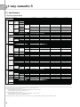
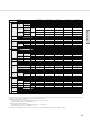
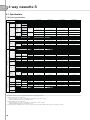
3
4 way cassette S
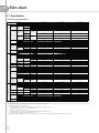
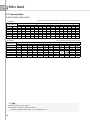
3-1. Specifications
1) Technical specifications
Model Name
Indoor Unit
Outdoor Unit
Mode
Capacity
Capacity
(Nominal)
Power Input
(Nominal)
Power
System
Current Input
(Nominal)
COP
Cooling *1)
(Min / Std / Max)
Heating *2)
(Min / Std / Max)
Cooling *1)
(Min / Std / Max)
Heating *2)
(Min / Std / Max)
Cooling *1)
(Min / Std / Max)
Heating *2)
(Min / Std / Max)
Nominal Cooling
Nominal Heating
Energy Grade Cooling / Heating
Option Code
Piping
Connections
Refrigerant
NS0714PXEA
RC071PHXEA
Heat Pump
2.2 / 7.1 / 8.0
7,500 / 24,200 / 27,300
1.9 / 8.0 / 9.0
6,500 / 27,300 / 30,700
NS0904DXEA
RC090DHXEA
Heat Pump
3.0 / 9.0 / 10.0
10,200 / 30,700 / 34,100
2.2 / 10.0 / 13.9
7,500 / 34,100 / 47,400
NS0904PXEA
RC090PHXEA
Heat Pump
2.5 / 9.0 / 10.0
8,500 / 30,700 / 34,100
2.3 / 10.0 / 13.9
7,800 / 34,100 / 47,400
0.35 / 2.21 / 4.00
0.35 / 1.92 / 4.00
0.6 / 2.8 / 3.7
0.6 / 2.5 / 3.7
0.35 / 2.22 / 4.00
0.35 / 1.95 / 4.00
0.46 / 2.77 / 5.2
0.48 / 2.5 / 5.2
2.0 / 10.5 / 21.0
2.1 / 9.5 / 18.0
3.0 / 12.5 / 18.7
3.0 / 11.0 / 18.7
2.0 / 10.5 / 21.0
2.1 / 9.5 / 18.0
2.5 / 12.2 / 22.7
2.4 / 11.0 / 23.0
3.70
4.10
A/A
014077-1360D9
-274750-370020
6.35 (1/4)
15.88 (5/8)
50.0
30.0
R410A
EEV
1.8
1, 2, 220~240, 50
Turbo Fan / BLDC
1
(C) 23.0 / 21.0 / 17.5
(H) 22.0 / 18.0 / 16.0
(C) 812 / 742 / 618
(H) 777 / 636 / 565
VP25 (OD 32, ID 25)
3.21
3.61
A/A
014077-1560E8
-275A64-3700020
9.52 (3/8)
15.88 (5/8)
50.0
30.0
R410A
EEV
3.0
1, 2, 220~240, 50
Turbo Fan / BLDC
1
3.60
4.00
A/A
014077-156219
-275A64-370040
9.52 (3/8)
15.88 (5/8)
50.0
30.0
R410A
EEV
3.0
1, 2, 220~240, 50
Turbo Fan / BLDC
1
24.5 / 21.0 / 17.5
27.5 / 22.5 / 18.0
865 / 742 / 618
971 / 795 / 636
mmAq
Pa
Ø, mm
3.21
3.62
A/A
014077-1660C8
-274750-370000
6.35 (1/4)
15.88 (5/8)
50.0
30.0
R410A
EEV
1.8
1, 2, 220~240, 50
Turbo Fan / BLDC
1
(C) 19.5 / 16.5 / 14.5
(H) 21.0 / 18.0 / 16.0
(C) 689 / 583 / 512
(H) 742 / 636 / 565
VP25 (OD 32, ID 25)
VP25 (OD 32, ID 25)
VP25 (OD 32, ID 25)
dB(A)
36 / 32 / 28
36 / 32 / 28
40 / 36 / 32
42 / 37 / 32
kg
kg
mm
mm
kg
kg
mm
mm
-
15
20
840 x 204 x 840
898 x 274 x 898
PC4NU(B)SKA / PC4NUSKE
5.9
8.4
950 x 45 x 950
1,005 x 100 x 1,005
Built-in
17
22
840 x 246 x 840
898 x 316 x 898
PC4NU(B)SKA / PC4NUSKE
5.9
8.4
950 x 45 x 950
1,005 x 100 x 1,005
Built-in
17
22
840 x 246 x 840
898 x 316 x 898
PC4NU(B)SKA / PC4NUSKE
5.9
8.4
950 x 45 x 950
1,005 x 100 x 1,005
Built-in
19
24
840 x 288 x 840
898 x 357 x 898
PC4NU(B)SKA / PC4NUSKE
5.9
8.4
950 x 45 x 950
1,005 x 100 x 1,005
Built-in
mm / liter/h
750 / 24
750 / 24
750 / 24
750 / 24
Ø, #, V, Hz
cc
CMM
CFM
Long life filter
1, 2, 220~240, 50
Twin BLDC Rotary
UG4T200FUAE4
POE
650
50.0 / 48.0
1,766 / 1,695
Long life filter
1, 2, 220~240, 50
Twin BLDC Rotary
UG4T200FUAE4
POE
650
50.0 / 48.0
1,766 / 1,695
Long life filter
1, 2, 220~240, 50
Twin BLDC Rotary
UG8T300FUBJU
POE
1,250
63.5 / 63.5
2,243 / 2,243
Long life filter
1, 2, 220~240, 50
Twin BLDC Rotary
UG8T300FUBJU
POE
1,250
63.5 / 59.0
2,243 / 2,084
dB(A)
49 / 51
49 / 51
51 / 52
52 / 53
kg
kg
mm
mm
°C
°C
55
59
880 x 798 x 310
1,023 x 891 x 413
-15 ~ 50
-20 ~ 24
55
59
880 x 798 x 310
1,023 x 891 x 413
-15 ~ 50
-20 ~ 24
72
77
940 x 998 x 330
995 x 1,096 x 426
-15 ~ 50
-20 ~ 24
72
77
940 x 998 x 330
995 x 1,096 x 426
-15 ~ 50
-20 ~ 24
kW
Btu/h
kW
Btu/h
kW
A
-
Liquid Pipe
Gas Pipe
Max. Length
Installation
Limitation
Max. Height
Type
Control Method
Factory Charging
Power Supply
Type
Motor
Output
Number of Unit
Fan
NS0714DXEA
RC071DHXEA
Heat Pump
2.2 / 7.1 / 8.0
7,500 / 24,200 / 27,300
1.9 / 8.0 / 9.0
6,500 / 27,300 / 30,700
Ø, mm(inch)
Ø, mm(inch)
m
m
kg
Ø, #, V, Hz
W
EA
CMM
Air Flow Rate
High / Mid / Low
CFM
Indoor Unit
Drain
Sound
External
Dimension
Panel Size
Additional
Accessories
External Static
Min / Std / Max
Pressure
Drain Pipe
Sound
High / Mid / Low
Pressure *3)
Net Weight
Shipping Weight
Net Dimensions (WxHxD)
Shipping Dimensions (WxHxD)
Panel model
Panel Net Weight
Shipping Weight
Net Dimensions (W×H×D)
Shipping Dimensions (W×H×D)
Drain pump
Max. Lifting
Drain pump
Height /
Displacement
Air Filter
Power Supply
Outdoor Unit
Compressor
Fan
Sound
External
Dimension
Operating
Temp. Range
Type
Model
Oil
Type
Initial Charge
Air Flow Rate
Cooling / Heating
Sound
Cooling / Heating
Pressure *3)
Net Weight
Shipping Weight
Net Dimensions (WxHxD)
Shipping Dimensions (WxHxD)
Cooling
Heating
*Specifications may be subject to change without prior notice for product improvement.
*1) Nominal cooling capacities are based on;
- Indoor temperature : 27°C DB, 19°C WB / Outdoor temperature : 35°C DB, 24°C WB
- Equivalent refrigerant piping : 5m, Level differences : 0m
*2) Norminal heating capacities are based on;
- Indoor temperature : 20°C DB, 15°C WB / Outdoor temperature : 7°C DB, 6°C WB
- Equivalent refrigerant piping : 5m, Level differences : 0m
*3) Sound pressure was acquired in an anechoic room. Thus actual noise level may be different depending on the installation conditions.
48
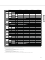
Model Name
Indoor Unit
Outdoor Unit
Mode
Capacity
Capacity
(Nominal)
Power Input
(Nominal)
System
Current Input
(Nominal)
COP
Nominal Cooling
Nominal Heating
Energy Grade Cooling / Heating
Option Code
Piping
Connections
Refrigerant
Type
Motor
Output
Number of Unit
Drain
Indoor Unit
Sound
External
Dimension
Air Flow Rate
High / Mid / Low
External Static
Min / Std / Max
Pressure
Drain Pipe
Sound
High / Mid / Low
Pressure *3)
Net Weight
Shipping Weight
Net Dimensions (WxHxD)
Shipping Dimensions (WxHxD)
Panel model
Panel Size
Additional
Accessories
Outdoor Unit
Fan
Sound
External
Dimension
Operating
Temp. Range
Type
Model
Oil
Type
Initial Charge
Air Flow Rate
Cooling / Heating
Sound
Cooling / Heating
Pressure *3)
Net Weight
Shipping Weight
Net Dimensions (WxHxD)
Shipping Dimensions (WxHxD)
Cooling
Heating
0.9 / 3.12 / 4.7
0.8 / 2.38 / 3.8
0.8 / 2.38 / 3.8
1.05 / 2.21 / 3.1
0.5 / 3.1 / 5.2
0.7 / 3.1 / 5.5
0.7 / 2.49 / 4.5
0.7 / 2.49 / 4.5
0.62 / 2.34 / 4.6
3.0 / 13.8 / 20.5
1.6 / 5.0 / 7.8
3.7 / 10.5 / 24.0
2.1 / 4.0 / 12.0
4.6 / 9.7 / 24.0
2.6 / 13.8 / 24.0
1.3 / 5.0 / 16.1
3.5 / 11.5 / 24.0
2.1 / 4.2 / 16.1
3.0 / 10.3 / 24.0
Ø, mm(inch)
Ø, mm(inch)
m
m
kg
Ø, #, V, Hz
W
EA
CMM
CFM
mmAq
Pa
Ø, mm
3.21
3.61
A/A
014077-156219
-276470-3700020
9.52 (3/8)
15.88 (5/8)
50.0
30.0
R410A
EEV
3.0
1, 2, 220~240, 50
Turbo Fan / BLDC
1
27.5 / 23.0 / 18.0
971 / 812 / 636
VP25 (OD 32, ID 25)
3.21
3.61
A/A
014077-156219
-276470-3700020
9.52 (3/8)
15.88 (5/8)
50.0
30.0
R410A
EEV
3.1
1, 2, 220~240, 50
Turbo Fan / BLDC
1
27.5 / 23.0 / 18.0
971 / 812 / 636
VP25 (OD 32, ID 25)
4.20
4.50
A/A
014077-157239
-276470-370040
9.52 (3/8)
15.88 (5/8)
75.0
30.0
R410A
EEV
3.4
1, 2, 220~240, 50
Turbo Fan / BLDC
1
30.0 / 24.0 / 18.0
1,059 / 848 / 636
VP25 (OD 32, ID 25)
4.20
4.50
A/A
014077-157239
-276470-370040
9.52 (3/8)
15.88 (5/8)
75.0
30.0
R410A
EEV
3.4
1, 2, 220~240, 50
Turbo Fan / BLDC
1
30.0 / 24.0 / 18.0
1,059 / 848 / 636
VP25 (OD 32, ID 25)
4.52
4.80
A/A
014077-156249
-276470-3700040
9.52 (3/8)
15.88 (5/8)
75.0
30.0
R410A
EEV
3.8
1, 2, 220~240, 50
Turbo Fan / BLDC
1
32.0 / 25.0 / 19.0
1,130 / 883 / 671
VP25 (OD 32, ID 25)
dB(A)
44 / 39 / 34
44 / 39 / 34
44 / 39 / 34
44 / 39 / 34
45 / 38.5 / 32
kg
kg
mm
mm
17
22
840 x 246 x 840
898 x 316 x 898
PC4NU(B)SKA /
PC4NUSKE
5.9
8.4
950 x 45 x 950
1,005 x 100 x 1,005
Built-in
17
22
840 x 246 x 840
898 x 316 x 898
PC4NU(B)SKA /
PC4NUSKE
5.9
8.4
950 x 45 x 950
1,005 x 100 x 1,005
Built-in
21
26
840 x 288 x 840
898 x 357 x 898
PC4NU(B)SKA /
PC4NUSKE
5.9
8.4
950 x 45 x 950
1,005 x 100 x 1,005
Built-in
21
26
840 x 288 x 840
898 x 357 x 898
PC4NU(B)SKA /
PC4NUSKE
5.9
8.4
950 x 45 x 950
1,005 x 100 x 1,005
Built-in
21
26
840 x 288 x 840
898 x 357 x 898
PC4NU(B)SKA /
PC4NUSKE
5.9
8.4
950 x 45 x 950
1,005 x 100 x 1,005
Built-in
A
-
-
Panel Net Weight
Shipping Weight
Net Dimensions (W×H×D)
Shipping Dimensions (W×H×D)
Drain pump
Max. Lifting
Drain pump
Height /
Displacement
Air Filter
Power Supply
Compressor
0.6 / 3.12 / 4.7
kW
Liquid Pipe
Gas Pipe
Max. Length
Installation
Limitation
Max. Height
Type
Control Method
Factory Charging
Power Supply
Fan
kW
Btu/h
kW
Btu/h
Specifications
Power
Cooling *1)
(Min / Std / Max)
Heating *2)
(Min / Std / Max)
Cooling *1)
(Min / Std / Max)
Heating *2)
(Min / Std / Max)
Cooling *1)
(Min / Std / Max)
Heating *2)
(Min / Std / Max)
NS1004DXEA
NS1004DXEA
NS1004PXEA
NS1004PXEA
NS1004ZXEA
RC100DHXEA
RC100DHXGA
RC100PHXEA
RC100PHXGA
RC100ZHXEA
Heat Pump
Heat Pump
Heat Pump
Heat Pump
Heat Pump
3.2 / 10.0 / 12.0
4.0 / 10.0 / 12.0
3.5 / 10.0 / 12.0
3.5 / 10.0 / 12.0
4.4 / 10.0 / 12.0
10,900 / 34,100 / 40,900 13,600 / 34,100 / 40,900 11,900 / 34,100 / 40,900 11,900 / 34,100 / 40,900 15,000 / 34,100 / 40,900
2.2 / 11.2 / 15.5
3.5 / 11.2 / 15.5
3.5 / 11.2 / 15.5
3.5 / 11.2 / 15.5
3.5 / 11.2 / 15.5
7,500 / 38,200 / 52,900 11,900 / 38,200 / 52,900 11,900 / 38,200 / 52,900 11,900 / 38,200 / 52,900 11,900 / 38,200 / 52,900
kg
kg
mm
mm
mm / liter/h
750 / 24
750 / 24
750 / 24
750 / 24
750 / 24
Ø, #, V, Hz
cc
CMM
CFM
Long life filter
1, 2, 220~240, 50
Twin BLDC Rotary
UG8T300FUBJU
POE
1,250
68.0 / 68.0
2,401 / 2,401
Long life filter
3, 4, 380~415, 50
Twin BLDC Rotary
UG5T450FUFJX
POE
1,750
65.5 / 65.5
2,313 / 2,313
Long life filter
1, 2, 220~240, 50
Twin BLDC Rotary
UG5T450FUEJX
POE
1,750
90.5 / 83.0
3,196 / 2,931
Long life filter
3, 4, 380~415, 50
Twin BLDC Rotary
UG5T450FUFJX
POE
1,750
90.5 / 83.0
3,196 / 2,931
Long life filter
1, 2, 220~240, 50
Twin BLDC Rotary
UG5T450FXAJX
POE
1,750
101.0 / 82.5
3,567 / 2,914
dB(A)
52 / 53
52 / 53
49 / 51
49 / 51
49 / 51
kg
kg
mm
mm
°C
°C
72
77
940 x 998 x 330
995 x 1,096 x 426
-15 ~ 50
-20 ~ 24
81
86
940 x 998 x 330
995 x 1,096 x 426
-15 ~ 50
-20 ~ 24
88
98
940 x 1,210 x 330
995 x 1,338 x 426
-15 ~ 50
-20 ~ 24
91
101
940 x 1,210 x 330
995 x 1,338 x 426
-15 ~ 50
-20 ~ 24
98
108
940 x 1,420 x 330
995 x 1,548 x 426
-15 ~ 50
-20 ~ 24
*Specifications may be subject to change without prior notice for product improvement.
*1) Nominal cooling capacities are based on;
- Indoor temperature : 27°C DB, 19°C WB / Outdoor temperature : 35°C DB, 24°C WB
- Equivalent refrigerant piping : 5m, Level differences : 0m
*2) Norminal heating capacities are based on;
- Indoor temperature : 20°C DB, 15°C WB / Outdoor temperature : 7°C DB, 6°C WB
- Equivalent refrigerant piping : 5m, Level differences : 0m
*3) Sound pressure was acquired in an anechoic room. Thus actual noise level may be different depending on the installation conditions.
49
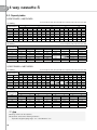
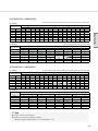
3
4 way cassette S
3-1. Specifications
1) Technical specifications
Model Name
Indoor Unit
Outdoor Unit
Mode
Capacity
Capacity
(Nominal)
Power Input
(Nominal)
Power
System
Current Input
(Nominal)
COP
Cooling *1)
(Min / Std / Max)
Heating *2)
(Min / Std / Max)
Cooling *1)
(Min / Std / Max)
Heating *2)
(Min / Std / Max)
Cooling *1)
(Min / Std / Max)
Heating *2)
(Min / Std / Max)
Nominal Cooling
Nominal Heating
Energy Grade Cooling / Heating
Option Code
Piping
Connections
Refrigerant
Type
Motor
Output
Number of Unit
Drain
Indoor Unit
Sound
External
Dimension
Panel Size
Additional
Accessories
Air Flow Rate
High / Mid / Low
External Static
Min / Std / Max
Pressure
Drain Pipe
Sound
High / Mid / Low
Pressure *3)
Net Weight
Shipping Weight
Net Dimensions (WxHxD)
Shipping Dimensions (WxHxD)
Panel model
Panel Net Weight
Shipping Weight
Net Dimensions (W×H×D)
Shipping Dimensions (W×H×D)
Drain pump
Max. Lifting
Drain pump
Height /
Displacement
Air Filter
Power Supply
Compressor
Outdoor Unit
Fan
Sound
External
Dimension
Operating
Temp. Range
NS1254DXEA
RC125DHXGA
Heat Pump
3.5 / 12.5 / 14.0
11,900 / 42,700 / 47,800
3.0 / 14.0 / 16.2
10,200 / 47,800 / 55,300
NS1254PXEA
RC125PHXEA
Heat Pump
3.5 / 12.5 / 14.0
11,900 / 42,700 / 47,800
3.5 / 14.0 / 16.2
11,900 / 47,800 / 55,300
NS1254PXEA
RC125PHXGA
Heat Pump
3.5 / 12.5 / 14.0
11,900 / 42,700 / 47,800
3.5 / 14.0 / 16.2
11,900 / 47,800 / 55,300
0.8 / 3.89 / 4.5
0.8 / 3.89 / 4.5
0.8 / 3.47 / 4.8
0.8 / 3.47 / 4.8
0.81 / 3.88 / 4.88
0.81 / 3.88 / 4.88
0.7 / 3.59 / 4.5
0.7 / 3.59 / 4.5
4.0 / 18.0 / 20.0
2.1 / 6.1 / 12.1
3.7 / 15.5 / 24.0
2.1 / 5.8 / 12.0
3.5 / 18.0 / 24.0
2.1 / 6.1 / 16.1
3.5 / 16.0 / 24.0
2.1 / 5.8 / 16.1
Ø, mm(inch)
Ø, mm(inch)
m
m
kg
Ø, #, V, Hz
W
EA
CMM
CFM
mmAq
Pa
Ø, mm
3.21
3.61
A/A
014077-15723A
-277D8C-370040
9.52 (3/8)
15.88 (5/8)
75.0
30.0
R410A
EEV
2.9
1, 2, 220~240, 50
Turbo Fan / BLDC
1
30.0 / 24.0 / 19.0
1,059 / 848 / 671
VP25 (OD 32, ID 25)
3.21
3.61
A/A
014077-15723A
-277D8C-370040
9.52 (3/8)
15.88 (5/8)
75.0
30.0
R410A
EEV
2.9
1, 2, 220~240, 50
Turbo Fan / BLDC
1
30.0 / 24.0 / 19.0
1,059 / 848 / 671
VP25 (OD 32, ID 25)
3.60
3.90
A/A
014077-15723A
-277D8C-370040
9.52 (3/8)
15.88 (5/8)
75.0
30.0
R410A
EEV
3.4
1, 2, 220~240, 50
Turbo Fan / BLDC
1
30.0 / 24.0 / 19.0
1,059 / 848 / 671
VP25 (OD 32, ID 25)
3.60
3.90
A/A
014077-15723A
-277D8C-370040
9.52 (3/8)
15.88 (5/8)
75.0
30.0
R410A
EEV
3.4
1, 2, 220~240, 50
Turbo Fan / BLDC
1
30.0 / 24.0 / 19.0
1,059 / 848 / 671
VP25 (OD 32, ID 25)
dB(A)
44 / 40 / 36
44 / 40 / 36
44 / 40 / 36
44 / 40 / 36
kg
kg
mm
mm
kg
kg
mm
mm
-
19
24
840 x 288 x 840
898 x 357 x 898
PC4NU(B)SKA / PC4NUSKE
5.9
8.4
950 x 45 x 950
1,005 x 100 x 1,005
Built-in
19
24
840 x 288 x 840
898 x 357 x 898
PC4NU(B)SKA / PC4NUSKE
5.9
8.4
950 x 45 x 950
1,005 x 100 x 1,005
Built-in
21
26
840 x 288 x 840
898 x 357 x 898
PC4NU(B)SKA / PC4NUSKE
5.9
8.4
950 x 45 x 950
1,005 x 100 x 1,005
Built-in
21
26
840 x 288 x 840
898 x 357 x 898
PC4NU(B)SKA / PC4NUSKE
5.9
8.4
950 x 45 x 950
1,005 x 100 x 1,005
Built-in
mm / liter/h
750 / 24
750 / 24
750 / 24
750 / 24
Ø, #, V, Hz
cc
CMM
CFM
Long life filter
1, 2, 220~240, 50
Twin BLDC Rotary
UG5T450FUEJX
POE
1,750
90.5 / 90.5
3,196 / 3,196
Long life filter
3, 4, 380~415, 50
Twin BLDC Rotary
UG5T450FUFJX
POE
1,750
90.5 / 90.5
3,196 / 3,196
Long life filter
1, 2, 220~240, 50
Twin BLDC Rotary
UG5T450FUEJX
POE
1,750
90.5 / 90.5
3,196 / 3,196
Long life filter
3, 4, 380~415, 50
Twin BLDC Rotary
UG5T450FUFJX
POE
1,750
90.5 / 90.5
3,196 / 3,196
dB(A)
51 / 52
51 / 52
51 / 52
51 / 52
kg
kg
mm
mm
°C
°C
88
98
940 x 1,210 x 330
995 x 1,338 x 426
-15 ~ 50
-20 ~ 24
91
101
940 x 1,210 x 330
995 x 1,338 x 426
-15 ~ 50
-20 ~ 24
88
98
940 x 1,210 x 330
995 x 1,338 x 426
-15 ~ 50
-20 ~ 24
91
101
940 x 1,210 x 330
995 x 1,338 x 426
-15 ~ 50
-20 ~ 24
kW
Btu/h
kW
Btu/h
kW
A
-
Liquid Pipe
Gas Pipe
Max. Length
Installation
Limitation
Max. Height
Type
Control Method
Factory Charging
Power Supply
Fan
NS1254DXEA
RC125DHXEB
Heat Pump
3.5 / 12.5 / 14.0
11,900 / 42,700 / 47,800
3.0 / 14.0 / 16.2
10,200 / 47,800 / 55,300
Type
Model
Oil
Type
Initial Charge
Air Flow Rate
Cooling / Heating
Sound
Cooling / Heating
Pressure *3)
Net Weight
Shipping Weight
Net Dimensions (WxHxD)
Shipping Dimensions (WxHxD)
Cooling
Heating
*Specifications may be subject to change without prior notice for product improvement.
*1) Nominal cooling capacities are based on;
- Indoor temperature : 27°C DB, 19°C WB / Outdoor temperature : 35°C DB, 24°C WB
- Equivalent refrigerant piping : 5m, Level differences : 0m
*2) Norminal heating capacities are based on;
- Indoor temperature : 20°C DB, 15°C WB / Outdoor temperature : 7°C DB, 6°C WB
- Equivalent refrigerant piping : 5m, Level differences : 0m
*3) Sound pressure was acquired in an anechoic room. Thus actual noise level may be different depending on the installation conditions.
50
Model Name
Indoor Unit
Outdoor Unit
Mode
Capacity
Capacity
(Nominal)
Power Input
(Nominal)
System
Current Input
(Nominal)
COP
Nominal Cooling
Nominal Heating
Energy Grade Cooling / Heating
Option Code
Piping
Connections
Refrigerant
Type
Motor
Output
Number of Unit
Drain
Indoor Unit
Sound
External
Dimension
Panel Size
Additional
Accessories
Air Flow Rate
High / Mid / Low
External Static
Min / Std / Max
Pressure
Drain Pipe
Sound
High / Mid / Low
Pressure *3)
Net Weight
Shipping Weight
Net Dimensions (WxHxD)
Shipping Dimensions (WxHxD)
Panel model
Panel Net Weight
Shipping Weight
Net Dimensions (W×H×D)
Shipping Dimensions (W×H×D)
Drain pump
Max. Lifting
Drain pump
Height /
Displacement
Air Filter
Power Supply
Outdoor Unit
Compressor
Fan
Sound
External
Dimension
Operating
Temp. Range
NS1404PXEA
RC140PHXEA
Heat Pump
4.4 / 14.0 / 15.5
15,000 / 47,800 / 52,900
3.5 / 16.0 / 20.0
11,900 / 54,600 / 68,200
NS1404PXEA
RC140PHXGA
Heat Pump
4.4 / 14.0 / 15.5
15,000 / 47,800 / 52,900
3.5 / 16.0 / 20.0
11,900 / 54,600 / 68,200
0.8 / 4.36 / 5.4
0.8 / 4.36 / 5.4
1.05 / 4.0 / 5.4
1.05 / 4.0 / 5.4
0.7 / 4.43 / 6.16
0.7 / 4.43 / 6.16
0.87 / 4.1 / 6.5
0.87 / 4.1 / 6.5
3.7 / 20.0 / 24
2.1 / 7.5 / 12.0
4.6 / 17.8 / 24.0
2.1 / 7.1 / 12.0
3.5 / 20.0 / 24
2.1 / 7.4 / 16.1
4.0 / 18.7 / 28.0
2.0 / 7.2 / 16.1
Ø, mm(inch)
Ø, mm(inch)
m
m
kg
Ø, #, V, Hz
W
EA
CMM
CFM
mmAq
Pa
Ø, mm
3.21
3.61
A/A
014077-15723B
-278CA0-370040
9.52 (3/8)
15.88 (5/8)
75.0
30.0
R410A
EEV
3.4
1, 2, 220~240, 50
Turbo Fan / BLDC
1
30.0 / 25.5 / 20.5
1,059 / 901 / 724
VP25 (OD 32, ID 25)
3.21
3.61
A/A
014077-15723B
-278CA0-370040
9.52 (3/8)
15.88 (5/8)
75.0
30.0
R410A
EEV
3.4
1, 2, 220~240, 50
Turbo Fan / BLDC
1
30.0 / 25.5 / 20.5
1,059 / 901 / 724
VP25 (OD 32, ID 25)
3.50
3.90
A/A
014077-15624B
-278CA0-370040
9.52 (3/8)
15.88 (5/8)
75.0
30.0
R410A
EEV
3.8
1, 2, 220~240, 50
Turbo Fan / BLDC
1
32.0 / 26.0 / 21.0
1,130 / 918 / 742
VP25 (OD 32, ID 25)
3.50
3.90
A/A
014077-15624B
-278CA0-370040
9.52 (3/8)
15.88 (5/8)
75.0
30.0
R410A
EEV
3.8
1, 2, 220~240, 50
Turbo Fan / BLDC
1
32.0 / 26.0 / 21.0
1,130 / 918 / 742
VP25 (OD 32, ID 25)
dB(A)
45 / 41.5 / 38
45 / 41.5 / 38
45 / 41.5 / 38
45 / 41.5 / 38
kg
kg
mm
mm
kg
kg
mm
mm
-
21
26
840 x 288 x 840
898 x 357 x 898
PC4NU(B)SKA / PC4NUSKE
5.9
8.4
950 x 45 x 950
1,005 x 100 x 1,005
Built-in
21
26
840 x 288 x 840
898 x 357 x 898
PC4NU(B)SKA / PC4NUSKE
5.9
8.4
950 x 45 x 950
1,005 x 100 x 1,005
Built-in
21
26
840 x 288 x 840
898 x 357 x 898
PC4NU(B)SKA / PC4NUSKE
5.9
8.4
950 x 45 x 950
1,005 x 100 x 1,005
Built-in
21
26
840 x 288 x 840
898 x 357 x 898
PC4NU(B)SKA / PC4NUSKE
5.9
8.4
950 x 45 x 950
1,005 x 100 x 1,005
Built-in
mm / liter/h
750 / 24
750 / 24
750 / 24
750 / 24
Ø, #, V, Hz
cc
CMM
CFM
Long life filter
1, 2, 220~240, 50
Twin BLDC Rotary
UG5T450FUEJX
POE
1,750
90.5 / 90.5
3,196 / 3,196
Long life filter
3, 4, 380~415, 50
Twin BLDC Rotary
UG5T450FUFJX
POE
1,750
90.5 / 90.5
3,196 / 3,196
Long life filter
1, 2, 220~240, 50
Twin BLDC Rotary
UG5T450FXAJX
POE
1,750
101.0 / 101.0
3,567 / 3,567
Long life filter
3, 4, 380~415, 50
Twin BLDC Rotary
UG5T450FXAJX
POE
1,750
101.0 / 101.0
3,567 / 3,567
dB(A)
52 / 54
52 / 54
51 / 53
51 / 53
kg
kg
mm
mm
°C
°C
88
98
940 x 1,210 x 330
995 x 1,338 x 426
-15 ~ 50
-20 ~ 24
91
101
940 x 1,210 x 330
995 x 1,338 x 426
-15 ~ 50
-20 ~ 24
98
108
940 x 1,420 x 330
995 x 1,548 x 426
-15 ~ 50
-20 ~ 24
101
111
940 x 1,420 x 330
995 x 1,548 x 426
-15 ~ 50
-20 ~ 24
kW
Btu/h
kW
Btu/h
kW
A
-
Liquid Pipe
Gas Pipe
Max. Length
Installation
Limitation
Max. Height
Type
Control Method
Factory Charging
Power Supply
Fan
NS1404DXEA
RC140DHXGA
Heat Pump
3.5 / 14.0 / 15.5
11,900 / 47,800 / 52,900
3.5 / 16.0 / 18.0
11,900 / 54,600 / 61,400
Type
Model
Oil
Type
Initial Charge
Air Flow Rate
Cooling / Heating
Sound
Cooling / Heating
Pressure *3)
Net Weight
Shipping Weight
Net Dimensions (WxHxD)
Shipping Dimensions (WxHxD)
Cooling
Heating
Specifications
Power
Cooling *1)
(Min / Std / Max)
Heating *2)
(Min / Std / Max)
Cooling *1)
(Min / Std / Max)
Heating *2)
(Min / Std / Max)
Cooling *1)
(Min / Std / Max)
Heating *2)
(Min / Std / Max)
NS1404DXEA
RC140DHXEB
Heat Pump
3.5 / 14.0 / 15.5
11,900 / 47,800 / 52,900
3.5 / 16.0 / 18.0
11,900 / 54,600 / 61,400
*Specifications may be subject to change without prior notice for product improvement.
*1) Nominal cooling capacities are based on;
- Indoor temperature : 27°C DB, 19°C WB / Outdoor temperature : 35°C DB, 24°C WB
- Equivalent refrigerant piping : 5m, Level differences : 0m
*2) Norminal heating capacities are based on;
- Indoor temperature : 20°C DB, 15°C WB / Outdoor temperature : 7°C DB, 6°C WB
- Equivalent refrigerant piping : 5m, Level differences : 0m
*3) Sound pressure was acquired in an anechoic room. Thus actual noise level may be different depending on the installation conditions.
51
3
4 way cassette S
3-2. Capacity tables
1) RC071DHXEA + NS0714DXEA
(1) Cooling
TC(Total Capacity, kW), SHC(Sensible Heat Capacity, kW), PI(Power Input, kW)
Indoor
Temperature(°C)
WB
14
16
18
19
22
24
DB
20
22
25
27
30
32
TC
6.67
6.84
7.00
7.18
7.35
7.53
-15
SHC
5.00
5.13
5.25
5.38
5.51
5.64
PI
1.67
1.71
1.75
1.79
1.84
1.88
TC
7.29
7.47
7.65
7.84
8.03
8.22
21
SHC
5.47
5.60
5.74
5.88
6.02
6.16
Outdoor Temperature (°C, DB)
35
PI
TC
SHC
PI
TC
1.59
6.60
4.95
2.05
6.70
1.63
6.76
5.07
2.11
6.87
1.67
6.93
5.20
2.16
7.03
1.71
7.21
7.10
5.33
2.21
1.75
7.27
5.45
2.26
7.38
1.80
7.44
5.58
2.32
7.56
(2) Heating
43
SHC
5.03
5.15
5.28
5.41
5.53
5.67
PI
3.08
3.16
3.24
3.32
3.40
3.48
TC
5.08
5.21
5.33
5.47
5.60
5.73
50
SHC
3.81
3.91
4.00
4.10
4.20
4.30
PI
2.64
2.70
2.77
2.84
2.90
2.97
TC(Total Capacity, kW), PI(Power Input, kW)
Indoor
Temperature(°C)
DB
16
18
20
21
22
24
Outdoor Temperature (°C, DB)
-10
7
PI
TC
2.81
8.16
2.78
8.08
2.76
8.00
2.73
7.92
2.70
7.84
2.67
7.76
-20
TC
4.49
4.45
4.40
4.36
4.32
4.27
PI
2.34
2.32
2.30
2.28
2.25
2.23
TC
6.58
6.52
6.45
6.39
6.32
6.26
24
PI
2.26
2.24
2.22
2.20
2.18
2.15
TC
9.67
9.57
9.48
9.38
9.29
9.20
PI
2.47
2.45
2.43
2.40
2.38
2.35
2) RC071PHXEA + NS0714PXEA
(1) Cooling
TC(Total Capacity, kW), SHC(Sensible Heat Capacity, kW), PI(Power Input, kW)
Indoor
Temperature(°C)
WB
14
16
18
19
22
24
DB
20
22
25
27
30
32
TC
7.07
7.24
7.42
7.60
7.78
7.97
-15
SHC
5.30
5.43
5.56
5.70
5.84
5.98
PI
1.67
1.71
1.76
1.80
1.84
1.89
TC
7.64
7.83
8.02
8.22
8.41
8.61
21
SHC
5.73
5.87
6.01
6.16
6.31
6.46
Outdoor Temperature (°C, DB)
35
PI
TC
SHC
PI
TC
1.65
6.60
4.95
1.79
6.83
1.69
6.76
5.07
1.83
7.00
1.73
6.93
5.20
1.87
7.17
1.77
7.10
5.33
1.92
7.35
1.81
7.27
5.45
1.97
7.52
1.86
7.44
5.58
2.01
7.70
(2) Heating
-20
TC
4.89
4.84
4.79
4.74
4.69
4.65
PI
2.26
2.24
2.22
2.20
2.17
2.15
TC
6.72
6.65
6.58
6.52
6.45
6.39
Outdoor Temperature (°C, DB)
-10
7
PI
TC
2.62
8.16
2.60
8.08
2.57
8.00
2.55
7.92
2.52
7.84
2.50
7.76
; Note
X Ratings shown are net capacities.
X Capacities are based on following conditions;
- Equivalent refrigerant piping length : 5m / Level difference : 0m.
52
PI
2.97
3.04
3.12
3.19
3.27
3.35
TC
5.30
5.43
5.57
5.71
5.84
5.98
50
SHC
3.98
4.08
4.18
4.28
4.38
4.49
PI
2.58
2.64
2.71
2.77
2.84
2.91
TC(Total Capacity, kW), PI(Power Input, kW)
Indoor
Temperature(°C)
DB
16
18
20
21
22
24
43
SHC
5.12
5.25
5.38
5.51
5.64
5.78
24
PI
1.99
1.97
1.95
1.93
1.91
1.89
TC
9.68
9.58
9.49
9.40
9.30
9.21
PI
2.35
2.33
2.30
2.28
2.26
2.24
3) RC090DHXEA + NS0904DXEA
(1) Cooling
TC(Total Capacity, kW), SHC(Sensible Heat Capacity, kW), PI(Power Input, kW)
Indoor
Temperature(°C)
DB
20
22
25
27
30
32
TC
9.63
9.86
10.11
10.36
10.60
10.86
PI
1.97
2.02
2.07
2.12
2.17
2.22
TC
10.28
10.53
10.79
11.06
11.32
11.59
21
SHC
8.22
8.43
8.63
8.84
9.06
9.27
Outdoor Temperature (°C, DB)
35
PI
TC
SHC
PI
TC
2.75
8.37
6.69
2.60
8.49
2.82
8.57
6.86
2.67
8.70
2.89
8.78
7.03
2.73
8.91
2.96
9.00
7.20
2.80
9.13
3.03
9.22
7.37
2.87
9.35
3.10
9.44
7.55
2.94
9.57
(2) Heating
43
SHC
6.79
6.96
7.13
7.30
7.48
7.66
PI
3.89
3.99
4.09
4.19
4.29
4.39
TC
6.32
6.48
6.64
6.80
6.96
7.13
50
SHC
5.06
5.18
5.31
5.44
5.57
5.70
PI
3.16
3.24
3.32
3.40
3.48
3.57
TC(Total Capacity, kW), PI(Power Input, kW)
Indoor
Temperature(°C)
DB
16
18
20
21
22
24
-20
TC
7.13
7.06
6.99
6.92
6.85
6.78
PI
3.49
3.46
3.42
3.39
3.35
3.32
TC
9.29
9.20
9.11
9.02
8.93
8.84
Outdoor Temperature (°C, DB)
-10
7
PI
TC
4.17
10.20
4.13
10.10
4.09
10.00
4.05
9.90
4.00
9.80
3.96
9.70
24
PI
2.83
2.80
2.77
2.74
2.71
2.69
TC
10.01
9.91
9.81
9.71
9.61
9.52
PI
2.79
2.76
2.74
2.71
2.68
2.65
4) RC090PHXEA + NS0904PXEA
(1) Cooling
TC(Total Capacity, kW), SHC(Sensible Heat Capacity, kW), PI(Power Input, kW)
Indoor
Temperature(°C)
WB
14
16
18
19
22
24
DB
20
22
25
27
30
32
TC
9.99
10.23
10.48
10.74
11.00
11.26
-15
SHC
7.99
8.19
8.39
8.59
8.80
9.01
PI
1.87
1.92
1.96
2.01
2.06
2.11
TC
10.67
10.94
11.21
11.48
11.76
12.04
21
SHC
8.54
8.75
8.97
9.19
9.41
9.63
Outdoor Temperature (°C, DB)
35
PI
TC
SHC
PI
TC
2.78
8.37
6.69
2.32
8.63
2.85
8.57
6.86
2.38
8.84
2.92
8.78
7.03
2.44
9.06
2.99
9.00
7.20
2.50
9.28
3.06
9.22
7.37
2.56
9.50
3.14
9.44
7.55
2.62
9.73
(2) Heating
PI
3.81
3.91
4.00
4.10
4.20
4.30
TC
6.51
6.67
6.83
7.00
7.17
7.34
50
SHC
5.21
5.33
5.47
5.60
5.73
5.87
PI
3.07
3.14
3.22
3.30
3.38
3.46
TC(Total Capacity, kW), PI(Power Input, kW)
Indoor
Temperature(°C)
DB
16
18
20
21
22
24
43
SHC
6.90
7.07
7.24
7.42
7.60
7.78
-20
TC
6.87
6.80
6.73
6.66
6.60
6.53
PI
3.25
3.22
3.19
3.16
3.12
3.09
TC
9.33
9.24
9.15
9.06
8.97
8.88
Outdoor Temperature (°C, DB)
-10
7
PI
TC
3.83
10.20
3.79
10.10
3.76
10.00
3.72
9.90
3.68
9.80
3.65
9.70
24
PI
2.55
2.53
2.50
2.48
2.45
2.43
TC
13.14
13.01
12.88
12.76
12.63
12.50
PI
2.88
2.85
2.82
2.79
2.76
2.74
; Note
X Ratings shown are net capacities.
X Capacities are based on following conditions;
- Equivalent refrigerant piping length : 5m / Level difference : 0m.
53
Specifications
WB
14
16
18
19
22
24
-15
SHC
7.70
7.89
8.09
8.28
8.48
8.69
3
4 way cassette S
3-2. Capacity tables
5) RC100DHXEA + NS1004DXEA
(1) Cooling
TC(Total Capacity, kW), SHC(Sensible Heat Capacity, kW), PI(Power Input, kW)
Indoor
Temperature(°C)
WB
14
16
18
19
22
24
DB
20
22
25
27
30
32
TC
10.23
10.48
10.74
11.00
11.27
11.54
-15
SHC
8.18
8.38
8.59
8.80
9.01
9.23
PI
2.73
2.80
2.87
2.94
3.01
3.08
TC
11.37
11.65
11.94
12.23
12.52
12.83
21
SHC
9.10
9.32
9.55
9.78
10.02
10.26
Outdoor Temperature (°C, DB)
35
PI
TC
SHC
PI
TC
3.57
9.30
7.44
2.90
8.56
3.66
9.53
7.62
2.97
8.77
3.75
9.76
7.81
3.05
8.98
3.84 10.00 8.00
3.12
9.20
3.93 10.24 8.19
3.19
9.42
4.03 10.49 8.39
3.27
9.65
(2) Heating
43
SHC
6.84
7.01
7.18
7.36
7.54
7.72
PI
4.28
4.38
4.49
4.60
4.71
4.83
TC
6.42
6.57
6.73
6.90
7.07
7.24
50
SHC
5.13
5.26
5.39
5.52
5.65
5.79
PI
3.53
3.62
3.71
3.80
3.89
3.98
TC(Total Capacity, kW), PI(Power Input, kW)
Indoor
Temperature(°C)
DB
16
18
20
21
22
24
-20
TC
7.96
7.88
7.80
7.72
7.64
7.57
PI
4.28
4.24
4.20
4.16
4.12
4.08
TC
10.21
10.11
10.01
9.91
9.81
9.71
Outdoor Temperature (°C, DB)
-10
7
PI
TC
4.75
11.43
4.71
11.31
4.66
11.20
4.61
11.09
4.57
10.98
4.52
10.87
24
PI
3.16
3.13
3.10
3.07
3.04
3.01
TC
14.44
14.30
14.16
14.02
13.88
13.74
PI
4.35
4.31
4.27
4.22
4.18
4.14
6) RC100DHXGA + NS1004DXEA
(1) Cooling
TC(Total Capacity, kW), SHC(Sensible Heat Capacity, kW), PI(Power Input, kW)
Indoor
Temperature(°C)
WB
14
16
18
19
22
24
DB
20
22
25
27
30
32
TC
8.55
8.76
8.98
9.20
9.42
9.65
-15
SHC
6.84
7.01
7.18
7.36
7.54
7.72
PI
1.86
1.91
1.95
2.00
2.05
2.10
TC
9.67
9.91
10.15
10.40
10.65
10.90
21
SHC
7.73
7.92
8.12
8.32
8.52
8.72
Outdoor Temperature (°C, DB)
35
PI
TC
SHC
PI
TC
2.04
9.30
7.44
2.90
8.86
2.09
9.53
7.62
2.97
9.08
2.14
9.76
7.81
3.05
9.30
2.19 10.00 8.00
3.12
9.53
2.24 10.24 8.19
3.19
9.76
2.30 10.49 8.39
3.27 10.00
(2) Heating
-20
TC
8.14
8.06
7.98
7.90
7.82
7.74
PI
4.36
4.31
4.27
4.23
4.19
4.15
TC
10.39
10.28
10.18
10.08
9.98
9.88
Outdoor Temperature (°C, DB)
-10
7
PI
TC
4.88
11.43
4.83
11.31
4.78
11.20
4.73
11.09
4.69
10.98
4.64
10.87
; Note
X Ratings shown are net capacities.
X Capacities are based on following conditions;
- Equivalent refrigerant piping length : 5m / Level difference : 0m.
54
PI
4.24
4.34
4.45
4.56
4.67
4.78
TC
6.69
6.86
7.03
7.20
7.37
7.55
50
SHC
5.36
5.49
5.62
5.76
5.90
6.04
PI
3.72
3.81
3.90
4.00
4.10
4.19
TC(Total Capacity, kW), PI(Power Input, kW)
Indoor
Temperature(°C)
DB
16
18
20
21
22
24
43
SHC
7.09
7.26
7.44
7.63
7.81
8.00
24
PI
3.16
3.13
3.10
3.07
3.04
3.01
TC
14.39
14.25
14.11
13.97
13.83
13.69
PI
3.72
3.69
3.65
3.61
3.58
3.54
7) RC100PHXEA + NS1004PXEA
(1) Cooling
TC(Total Capacity, kW), SHC(Sensible Heat Capacity, kW), PI(Power Input, kW)
Indoor
Temperature(°C)
DB
20
22
25
27
30
32
TC
10.32
10.57
10.83
11.10
11.37
11.64
PI
1.77
1.81
1.85
1.90
1.95
1.99
TC
11.44
11.72
12.00
12.30
12.60
12.90
21
SHC
9.15
9.37
9.60
9.84
10.08
10.32
Outdoor Temperature (°C, DB)
35
PI
TC
SHC
PI
TC
3.25
9.30
7.44
2.21
9.48
3.33
9.53
7.62
2.27
9.72
3.42
9.76
7.81
2.32
9.96
3.50 10.00 8.00
2.38 10.20
3.58 10.24 8.19
2.44 10.44
3.67 10.49 8.39
2.50 10.70
(2) Heating
43
SHC
7.59
7.77
7.96
8.16
8.36
8.56
PI
4.46
4.57
4.68
4.80
4.92
5.03
TC
6.51
6.67
6.83
7.00
7.17
7.34
50
SHC
5.21
5.33
5.47
5.60
5.73
5.87
PI
3.35
3.43
3.51
3.60
3.69
3.77
TC(Total Capacity, kW), PI(Power Input, kW)
Indoor
Temperature(°C)
DB
16
18
20
21
22
24
-20
TC
10.71
10.61
10.50
10.40
10.29
10.19
PI
5.00
4.95
4.90
4.85
4.80
4.75
TC
11.22
11.11
11.00
10.89
10.78
10.67
Outdoor Temperature (°C, DB)
-10
7
PI
TC
4.90
11.43
4.85
11.31
4.80
11.20
4.75
11.09
4.70
10.98
4.66
10.87
24
PI
2.54
2.51
2.49
2.47
2.44
2.42
TC
15.61
15.45
15.30
15.15
15.00
14.85
PI
3.88
3.84
3.80
3.76
3.72
3.69
8) RC100PHXGA + NS1004PXEA
(1) Cooling
TC(Total Capacity, kW), SHC(Sensible Heat Capacity, kW), PI(Power Input, kW)
Indoor
Temperature(°C)
WB
14
16
18
19
22
24
DB
20
22
25
27
30
32
TC
10.51
10.76
11.03
11.30
11.57
11.85
-15
SHC
8.40
8.61
8.82
9.04
9.26
9.48
PI
1.86
1.91
1.95
2.00
2.05
2.10
TC
11.62
11.91
12.20
12.50
12.80
13.11
21
SHC
9.30
9.53
9.76
10.00
10.24
10.49
Outdoor Temperature (°C, DB)
35
PI
TC
SHC
PI
TC
2.23
9.30
7.44
2.21
9.76
2.29
9.53
7.62
2.27 10.00
2.34
9.76
7.81
2.32 10.25
2.40 10.00 8.00
2.38 10.50
2.46 10.24 8.19
2.44 10.75
2.52 10.49 8.39
2.50 11.01
(2) Heating
PI
4.28
4.38
4.49
4.60
4.71
4.82
TC
6.51
6.67
6.83
7.00
7.17
7.34
50
SHC
5.21
5.33
5.47
5.60
5.73
5.87
PI
3.35
3.43
3.51
3.60
3.69
3.77
TC(Total Capacity, kW), PI(Power Input, kW)
Indoor
Temperature(°C)
DB
16
18
20
21
22
24
43
SHC
7.81
8.00
8.20
8.40
8.60
8.81
-20
TC
11.02
10.91
10.80
10.69
10.59
10.48
PI
5.41
5.35
5.30
5.25
5.19
5.14
TC
11.73
11.62
11.50
11.39
11.27
11.16
Outdoor Temperature (°C, DB)
-10
7
PI
TC
5.18
11.43
5.13
11.31
5.08
11.20
5.02
11.09
4.97
10.98
4.92
10.87
24
PI
2.54
2.51
2.49
2.47
2.44
2.42
TC
17.33
17.16
16.99
16.82
16.65
16.49
PI
4.16
4.12
4.08
4.04
4.00
3.96
; Note
X Ratings shown are net capacities.
X Capacities are based on following conditions;
- Equivalent refrigerant piping length : 5m / Level difference : 0m.
55
Specifications
WB
14
16
18
19
22
24
-15
SHC
8.26
8.46
8.67
8.88
9.09
9.31
3
4 way cassette S
3-2. Capacity tables
9) RC100ZHXEA + NS1004ZXEA
(1) Cooling
TC(Total Capacity, kW), SHC(Sensible Heat Capacity, kW), PI(Power Input, kW)
Indoor
Temperature(°C)
WB
14
16
18
19
22
24
DB
20
22
25
27
30
32
TC
10.47
10.73
11.00
11.27
11.54
11.81
-15
SHC
8.38
8.59
8.80
9.01
9.23
9.45
PI
1.63
1.67
1.71
1.75
1.80
1.84
TC
11.62
11.91
12.20
12.50
12.80
13.11
21
SHC
9.30
9.53
9.76
10.00
10.24
10.49
Outdoor Temperature (°C, DB)
35
PI
TC
SHC
PI
TC
1.86
9.30
7.44
2.06
9.76
1.91
9.53
7.62
2.11 10.00
1.95
9.76
7.81
2.17 10.25
2.00 10.00 8.00
2.22 10.50
2.05 10.24 8.19
2.27 10.75
2.10 10.49 8.39
2.33 11.01
(2) Heating
43
SHC
7.81
8.00
8.20
8.40
8.60
8.81
PI
3.40
3.48
3.57
3.66
3.74
3.83
TC
8.16
8.36
8.56
8.77
8.98
9.20
50
SHC
6.53
6.69
6.85
7.02
7.19
7.36
PI
3.87
3.96
4.06
4.16
4.26
4.36
TC(Total Capacity, kW), PI(Power Input, kW)
Indoor
Temperature(°C)
DB
16
18
20
21
22
24
-20
TC
9.70
9.60
9.51
9.41
9.32
9.22
PI
4.35
4.31
4.27
4.23
4.18
4.14
TC
13.40
13.26
13.13
13.00
12.87
12.74
Outdoor Temperature (°C, DB)
-10
7
PI
TC
5.38
11.43
5.33
11.31
5.28
11.20
5.22
11.09
5.17
10.98
5.12
10.87
24
PI
2.38
2.36
2.34
2.31
2.29
2.27
TC
14.75
14.60
14.46
14.31
14.17
14.03
PI
2.75
2.72
2.69
2.67
2.64
2.61
10) RC125DHXEB + NS1254DXEA
(1) Cooling
TC(Total Capacity, kW), SHC(Sensible Heat Capacity, kW), PI(Power Input, kW)
Indoor
Temperature(°C)
WB
14
16
18
19
22
24
DB
20
22
25
27
30
32
TC
11.63
11.92
12.21
12.51
12.81
13.12
-15
SHC
9.31
9.53
9.77
10.01
10.25
10.50
PI
2.28
2.34
2.39
2.45
2.51
2.57
TC
13.26
13.58
13.92
14.26
14.60
14.95
21
SHC
10.61
10.87
11.13
11.41
11.68
11.96
Outdoor Temperature (°C, DB)
35
PI
TC
SHC
PI
TC
3.29 11.62 9.30
3.63
9.65
3.37 11.91 9.53
3.72
9.89
3.45 12.20 9.76
3.81 10.13
3.54 12.50 10.00 3.90 10.38
3.62 12.80 10.24 3.99 10.63
3.71 13.11 10.49 4.09 10.88
(2) Heating
-20
TC
11.12
11.01
10.90
10.79
10.68
10.58
PI
5.16
5.11
5.06
5.01
4.96
4.91
TC
11.49
11.37
11.26
11.15
11.04
10.93
Outdoor Temperature (°C, DB)
-10
7
PI
TC
5.25
14.28
5.19
14.14
5.14
14.00
5.09
13.86
5.04
13.72
4.99
13.58
; Note
X Ratings shown are net capacities.
X Capacities are based on following conditions;
- Equivalent refrigerant piping length : 5m / Level difference : 0m.
56
PI
3.66
3.75
3.84
3.93
4.03
4.12
TC
6.97
7.14
7.32
7.50
7.68
7.86
50
SHC
5.58
5.72
5.86
6.00
6.14
6.29
PI
3.19
3.27
3.35
3.43
3.52
3.60
TC(Total Capacity, kW), PI(Power Input, kW)
Indoor
Temperature(°C)
DB
16
18
20
21
22
24
43
SHC
7.72
7.91
8.10
8.30
8.50
8.71
24
PI
3.96
3.92
3.88
3.84
3.80
3.76
TC
17.55
17.37
17.20
17.03
16.86
16.69
PI
4.40
4.36
4.32
4.27
4.23
4.19
11) RC125DHXGA + NS1254DXEA
(1) Cooling
TC(Total Capacity, kW), SHC(Sensible Heat Capacity, kW), PI(Power Input, kW)
Indoor
Temperature(°C)
DB
20
22
25
27
30
32
TC
11.61
11.89
12.19
12.49
12.78
13.09
PI
2.38
2.43
2.49
2.56
2.62
2.68
TC
13.34
13.66
14.00
14.35
14.69
15.04
21
SHC
10.67
10.93
11.20
11.48
11.75
12.03
Outdoor Temperature (°C, DB)
35
PI
TC
SHC
PI
TC
3.44 11.62 9.30
3.63
9.67
3.52 11.91 9.53
3.72
9.90
3.61 12.20 9.76
3.81 10.15
3.70 12.50 10.00 3.90 10.40
3.78 12.80 10.24 3.99 10.65
3.88 13.11 10.49 4.09 10.90
(2) Heating
43
SHC
7.73
7.92
8.12
8.32
8.52
8.72
PI
4.74
4.86
4.97
5.10
5.22
5.34
TC
7.10
7.27
7.45
7.64
7.82
8.01
50
SHC
5.68
5.82
5.96
6.11
6.25
6.40
PI
4.16
4.26
4.37
4.47
4.58
4.69
TC(Total Capacity, kW), PI(Power Input, kW)
Indoor
Temperature(°C)
DB
16
18
20
21
22
24
-20
TC
11.43
11.31
11.20
11.09
10.98
10.87
PI
5.43
5.38
5.32
5.27
5.22
5.17
TC
12.77
12.64
12.52
12.39
12.27
12.15
Outdoor Temperature (°C, DB)
-10
7
PI
TC
6.31
14.28
6.25
14.14
6.19
14.00
6.13
13.86
6.07
13.72
6.01
13.58
24
PI
3.96
3.92
3.88
3.84
3.80
3.76
TC
17.55
17.37
17.20
17.03
16.86
16.69
PI
4.51
4.47
4.42
4.38
4.33
4.29
12) RC125PHXEA + NS1254PXEA
(1) Cooling
TC(Total Capacity, kW), SHC(Sensible Heat Capacity, kW), PI(Power Input, kW)
Indoor
Temperature(°C)
WB
14
16
18
19
22
24
DB
20
22
25
27
30
32
TC
11.62
11.91
12.20
12.50
12.80
13.11
-15
SHC
9.30
9.53
9.76
10.00
10.24
10.49
PI
1.94
1.99
2.03
2.08
2.13
2.19
TC
13.29
13.62
13.96
14.30
14.64
14.99
21
SHC
10.64
10.90
11.17
11.44
11.71
12.00
Outdoor Temperature (°C, DB)
35
PI
TC
SHC
PI
TC
3.16 11.62 9.30
3.23 10.40
3.24 11.91 9.53
3.31 10.66
3.32 12.20 9.76
3.39 10.92
3.40 12.50 10.00 3.47 11.19
3.48 12.80 10.24 3.55 11.46
3.57 13.11 10.49 3.64 11.73
(2) Heating
PI
4.28
4.38
4.49
4.60
4.71
4.82
TC
7.07
7.24
7.42
7.60
7.78
7.97
50
SHC
5.65
5.79
5.93
6.08
6.23
6.38
PI
3.16
3.24
3.32
3.40
3.48
3.57
TC(Total Capacity, kW), PI(Power Input, kW)
Indoor
Temperature(°C)
DB
16
18
20
21
22
24
43
SHC
8.32
8.53
8.74
8.95
9.17
9.39
-20
TC
11.22
11.11
11.00
10.89
10.78
10.67
PI
5.20
5.15
5.10
5.05
5.00
4.95
TC
12.21
12.09
11.97
11.85
11.73
11.62
Outdoor Temperature (°C, DB)
-10
7
PI
TC
5.18
14.28
5.13
14.14
5.08
14.00
5.02
13.86
4.97
13.72
4.92
13.58
24
PI
3.66
3.63
3.59
3.55
3.52
3.48
TC
17.64
17.46
17.29
17.12
16.94
16.78
PI
4.16
4.12
4.08
4.04
4.00
3.96
; Note
X Ratings shown are net capacities.
X Capacities are based on following conditions;
- Equivalent refrigerant piping length : 5m / Level difference : 0m.
57
Specifications
WB
14
16
18
19
22
24
-15
SHC
9.29
9.51
9.75
9.99
10.23
10.47
3
4 way cassette S
3-2. Capacity tables
13) RC125PHXGA + NS1254PXEA
(1) Cooling
TC(Total Capacity, kW), SHC(Sensible Heat Capacity, kW), PI(Power Input, kW)
Indoor
Temperature(°C)
WB
14
16
18
19
22
24
DB
20
22
25
27
30
32
TC
11.71
12.00
12.30
12.60
12.90
13.21
-15
SHC
9.37
9.60
9.84
10.08
10.32
10.57
PI
2.14
2.19
2.24
2.30
2.36
2.41
TC
13.39
13.72
14.05
14.40
14.75
15.10
21
SHC
10.71
10.97
11.24
11.52
11.80
12.08
Outdoor Temperature (°C, DB)
35
PI
TC
SHC
PI
TC
3.25 11.62 9.30
3.25 10.41
3.33 11.91 9.53
3.33 10.67
3.42 12.20 9.76
3.42 10.93
3.50 12.50 10.00 3.50 11.20
3.58 12.80 10.24 3.58 11.47
3.67 13.11 10.49 3.67 11.74
(2) Heating
43
SHC
8.33
8.54
8.74
8.96
9.18
9.40
PI
4.74
4.86
4.98
5.10
5.22
5.35
TC
7.16
7.33
7.52
7.70
7.88
8.07
50
SHC
5.73
5.87
6.01
6.16
6.31
6.46
PI
4.09
4.19
4.29
4.40
4.51
4.61
TC(Total Capacity, kW), PI(Power Input, kW)
Indoor
Temperature(°C)
DB
16
18
20
21
22
24
-20
TC
11.53
11.41
11.30
11.19
11.08
10.96
PI
5.41
5.35
5.30
5.25
5.19
5.14
TC
12.24
12.12
12.00
11.88
11.76
11.64
Outdoor Temperature (°C, DB)
-10
7
PI
TC
5.20
14.28
5.15
14.14
5.10
14.00
5.05
13.86
5.00
13.72
4.95
13.58
24
PI
3.66
3.63
3.59
3.55
3.52
3.48
TC
17.65
17.47
17.30
17.13
16.96
16.79
PI
4.18
4.14
4.10
4.06
4.02
3.98
14) RC140DHXEB + NS1404DXEA
(1) Cooling
TC(Total Capacity, kW), SHC(Sensible Heat Capacity, kW), PI(Power Input, kW)
Indoor
Temperature(°C)
WB
14
16
18
19
22
24
DB
20
22
25
27
30
32
TC
13.00
13.32
13.65
13.98
14.32
14.66
-15
SHC
10.40
10.66
10.92
11.19
11.45
11.73
PI
3.52
3.61
3.70
3.79
3.88
3.97
TC
14.88
15.25
15.62
16.01
16.39
16.78
21
SHC
11.91
12.20
12.50
12.81
13.11
13.43
Outdoor Temperature (°C, DB)
35
PI
TC
SHC
PI
TC
4.42 13.02 10.41 4.05 12.69
4.53 13.34 10.67 4.15 13.00
4.64 13.66 10.93 4.26 13.32
4.75 14.00 11.20 4.36 13.65
4.87 14.34 11.47 4.46 13.98
4.98 14.68 11.74 4.57 14.31
(2) Heating
-20
TC
12.24
12.12
12.00
11.88
11.76
11.64
PI
6.32
6.26
6.20
6.14
6.08
6.02
TC
13.58
13.45
13.31
13.18
13.05
12.92
Outdoor Temperature (°C, DB)
-10
7
PI
TC
6.13
16.32
6.07
16.16
6.01
16.00
5.95
15.84
5.89
15.68
5.83
15.52
; Note
X Ratings shown are net capacities.
X Capacities are based on following conditions;
- Equivalent refrigerant piping length : 5m / Level difference : 0m.
58
PI
5.95
6.10
6.25
6.40
6.56
6.71
TC
8.37
8.57
8.78
9.00
9.22
9.44
50
SHC
6.69
6.86
7.03
7.20
7.37
7.55
PI
3.63
3.72
3.81
3.90
3.99
4.09
TC(Total Capacity, kW), PI(Power Input, kW)
Indoor
Temperature(°C)
DB
16
18
20
21
22
24
43
SHC
10.15
10.40
10.66
10.92
11.18
11.45
24
PI
4.52
4.47
4.43
4.39
4.34
4.30
TC
19.48
19.29
19.10
18.91
18.72
18.53
PI
4.49
4.44
4.40
4.36
4.31
4.27
15) RC140DHXGA + NS1404DXEA
(1) Cooling
TC(Total Capacity, kW), SHC(Sensible Heat Capacity, kW), PI(Power Input, kW)
Indoor
Temperature(°C)
DB
20
22
25
27
30
32
TC
13.00
13.32
13.65
13.98
14.32
14.66
PI
3.52
3.61
3.70
3.79
3.88
3.97
TC
14.88
15.25
15.62
16.01
16.39
16.78
Outdoor Temperature (°C, DB)
35
PI
TC
SHC
PI
TC
4.42 13.02 10.41 4.05 12.69
4.53 13.34 10.67 4.15 13.00
4.64 13.66 10.93 4.26 13.32
4.75 14.00 11.20 4.36 13.65
4.87 14.34 11.47 4.46 13.98
4.98 14.68 11.74 4.57 14.31
21
SHC
11.91
12.20
12.50
12.81
13.11
13.43
(2) Heating
43
SHC
10.15
10.40
10.66
10.92
11.18
11.45
PI
5.95
6.10
6.25
6.40
6.56
6.71
TC
8.46
8.67
8.88
9.10
9.32
9.54
50
SHC
6.77
6.93
7.11
7.28
7.45
7.63
PI
4.46
4.57
4.68
4.80
4.92
5.03
TC(Total Capacity, kW), PI(Power Input, kW)
Indoor
Temperature(°C)
DB
16
18
20
21
22
24
-20
TC
12.75
12.63
12.50
12.38
12.25
12.13
PI
6.53
6.46
6.40
6.34
6.27
6.21
TC
13.58
13.45
13.31
13.18
13.05
12.92
Outdoor Temperature (°C, DB)
-10
7
PI
TC
6.13
16.32
6.07
16.16
6.01
16.00
5.95
15.84
5.89
15.68
5.83
15.52
24
PI
4.52
4.47
4.43
4.39
4.34
4.30
TC
19.53
19.34
19.15
18.96
18.77
18.58
PI
4.51
4.46
4.42
4.38
4.33
4.29
16) RC140PHXEA + NS1404PXEA
(1) Cooling
TC(Total Capacity, kW), SHC(Sensible Heat Capacity, kW), PI(Power Input, kW)
Indoor
Temperature(°C)
WB
14
16
18
19
22
24
DB
20
22
25
27
30
32
TC
13.02
13.34
13.66
14.00
14.34
14.68
-15
SHC
10.41
10.67
10.93
11.20
11.47
11.74
PI
1.81
1.86
1.90
1.95
2.00
2.04
TC
14.88
15.24
15.62
16.00
16.38
16.78
21
SHC
11.90
12.19
12.49
12.80
13.11
13.42
Outdoor Temperature (°C, DB)
35
PI
TC
SHC
PI
TC
2.37 13.02 10.41 3.72 12.82
2.43 13.34 10.67 3.81 13.13
2.49 13.66 10.93 3.90 13.45
2.55 14.00 11.20 4.00 13.78
2.61 14.34 11.47 4.10 14.11
2.67 14.68 11.74 4.19 14.45
(2) Heating
PI
5.71
5.85
5.99
6.14
6.29
6.44
TC
8.37
8.57
8.78
9.00
9.22
9.44
50
SHC
6.69
6.86
7.03
7.20
7.37
7.55
PI
3.44
3.52
3.61
3.70
3.79
3.88
TC(Total Capacity, kW), PI(Power Input, kW)
Indoor
Temperature(°C)
DB
16
18
20
21
22
24
43
SHC
10.25
10.50
10.76
11.03
11.29
11.56
-20
TC
12.34
12.22
12.10
11.98
11.86
11.74
PI
6.05
5.99
5.94
5.88
5.82
5.76
TC
14.49
14.35
14.21
14.06
13.92
13.78
Outdoor Temperature (°C, DB)
-10
7
PI
TC
6.36
16.32
6.29
16.16
6.23
16.00
6.17
15.84
6.11
15.68
6.04
15.52
24
PI
4.18
4.14
4.10
4.06
4.02
3.98
TC
20.26
20.06
19.86
19.66
19.47
19.27
PI
4.48
4.43
4.39
4.35
4.30
4.26
; Note
X Ratings shown are net capacities.
X Capacities are based on following conditions;
- Equivalent refrigerant piping length : 5m / Level difference : 0m.
59
Specifications
WB
14
16
18
19
22
24
-15
SHC
10.40
10.66
10.92
11.19
11.45
11.73
3
4 way cassette S
3-2. Capacity tables
17) RC140PHXGA + NS1404PXEA
(1) Cooling
TC(Total Capacity, kW), SHC(Sensible Heat Capacity, kW), PI(Power Input, kW)
Indoor
Temperature(°C)
WB
14
16
18
19
22
24
DB
20
22
25
27
30
32
TC
13.11
13.43
13.76
14.10
14.44
14.78
-15
SHC
10.49
10.75
11.01
11.28
11.55
11.83
PI
1.58
1.62
1.66
1.70
1.74
1.78
TC
14.97
15.34
15.71
16.10
16.49
16.88
21
SHC
11.97
12.27
12.57
12.88
13.19
13.51
Outdoor Temperature (°C, DB)
35
PI
TC
SHC
PI
TC
3.93 13.02 10.41 3.72 12.59
4.03 13.34 10.67 3.81 12.90
4.13 13.66 10.93 3.90 13.22
4.23 14.00 11.20 4.00 13.54
4.33 14.34 11.47 4.10 13.87
4.44 14.68 11.74 4.19 14.20
(2) Heating
-20
TC
12.80
12.68
12.55
12.42
12.30
12.18
PI
6.30
6.23
6.17
6.11
6.05
5.99
TC
16.32
16.16
16.00
15.84
15.68
15.52
Outdoor Temperature (°C, DB)
-10
7
PI
TC
7.09
16.32
7.02
16.16
6.95
16.00
6.88
15.84
6.81
15.68
6.74
15.52
; Note
X Ratings shown are net capacities.
X Capacities are based on following conditions;
- Equivalent refrigerant piping length : 5m / Level difference : 0m.
60
PI
5.82
5.97
6.11
6.26
6.41
6.57
TC
10.36
10.61
10.87
11.14
11.41
11.68
50
SHC
8.29
8.49
8.70
8.91
9.13
9.34
PI
5.05
5.18
5.31
5.44
5.57
5.70
TC(Total Capacity, kW), PI(Power Input, kW)
Indoor
Temperature(°C)
DB
16
18
20
21
22
24
43
SHC
10.07
10.32
10.57
10.83
11.09
11.36
24
PI
4.18
4.14
4.10
4.06
4.02
3.98
TC
19.67
19.47
19.28
19.09
18.90
18.71
PI
4.39
4.34
4.30
4.26
4.21
4.17
3-3 . Dimensional drawing
Unit:mm
6
890~910 (Celling opening)
735 (Suspension position)
735 (Suspension position)
950
6
Specifications
890~910 (Celling opening)
950
5
840
370
346
185
1
2
55
55
840
55
96
120
55
3
B
C B AA
28
45
86
164
216
D
240
270
300
330
Sub duct connection
4
80
E
Fresh Air Intake Hole(ø100)
4-ø3.3
80.0
195
No.
Name
1
Liquid pipe connection
Gas pipe connection
Drain pipe connection
Conduit for power supply & communication wiring
Air inlet grille
Air outlet louver
2
3
4
5
6
A
B
C
D
mm
mm
mm
mm
7071D7
204
225
253
190
Description
7.1kW
9.0/10.0/12.5/14.0kW
Ø6.35mm (1/4") Flare
Ø9.52mm (3/8") Flare
Ø15.88mm (5/8") Flare
VP25 (OD32, ID25)
-
Description
7071P7, 7090/100D7
7090/100P7, 7125/140D(P)7, 7100Z7
246
288
267
309
295
337
215
215
61
3
4 way cassette S
3-4. PCB connector lay-out
Ê AC
Ê DC
No.
CN #
Color
1
TB01
BLK
2
19
CN101
CN73
WHT
WHT
62
Function
1(L), 2(N) : Input POWER
L, N : Auto Grill Power
Earth Wire
BLDC Fan Motor
No.
3
4
5
6
7
8
9
10
11
12
13
14
15
16
17
18
20
21
CN #
CN41
CN83
CN91
CN61
CN60
Color
WHT
RED
WHT
BLU
WHT
TB02
BLK
CN88
CN81
CN10
CN45
CN75
CN51
CN42
CN74
CN77
CN76
WHT
RED
BLK
YEL
BLU
BLK
WHT
YEL
BLK
YEL
Function
ROOM Temp. sensor
External Control(On/Off)
Panel Display
Louver 3/4
Louver 1/2
COM1
DC12V
COM2
Micom-Download(AS-PRO)
Error Check, Oper. Check
Micom-Download
SPI
Ventilator
Float switch sensor
EVA-IN, EVA-OUT Temp. sensor
AC Drain Pump
AUTO GRILL SIGNAL
DC Drain Pump
3-5. Electrical wiring diagram
Specifications
63
3
4 way cassette S
3-6. Sound pressure level
1) Operation sound level
Unit : dB(A)
Model
NS0714DXEA
NS0714PXEA
NS0904DXEA
NS0904PXEA
NS1004DXEA
NS1004PXEA
NS1004ZXEA
1.5m
Microphone
High
36
36
40
42
44
44
45
Unit : dB(A)
Model
NS1254DXEA
NS1254PXEA
NS1404DXEA
NS1404PXEA
Low
28
28
32
32
34
34
32
High
44
44
45
45
Low
36
36
38
38
; Note
X These operation values were obtained in an anechoic room. Sound pressure level will vary depending on a range of
factors such as the construction of the particular room where the equipment is installed.
X Operation sound level may differ depending on operation and ambient conditions.
2) NC curves
(1) NS0714DXEA
(2) NS0714PXEA
45
0%
*+)*
0%
35
0%
30
.19
0%
25
0%
20
0%
15
0%
10
5
63
125
250
500
1000
2000
4000
*+)*
0%
35
0%
30
.19
0%
25
0%
20
0%
15
0%
10
8000
63
125
250
500
1000
2000
4000
*+)*
0%
40
0%
35
.19
0%
30
0%
25
0%
20
0%
15
0%
10
5
Sound pressure level (dB)
45
63
125
250
500
1000
2000
4000
8000
0%
.19
0%
25
0%
20
0%
15
0%
10
125
250
500
1000
2000
4000
8000
55
*+)*
40
0%
.19
0%
30
0%
25
0%
20
0%
15
0%
10
5
Octave band center frequency(Hz)
0%
30
(6) NS1004PXEA
0%
35
0%
35
63
50
45
*+)*
40
Octave band center frequency(Hz)
55
50
45
8000
(5) NS1004DXEA
55
50
5
Octave band center frequency(Hz)
(4) NS0904PXEA
Sound pressure level (dB)
40
0%
5
Octave band center frequency(Hz)
64
45
Sound pressure level (dB)
40
55
50
Sound pressure level (dB)
55
50
Sound pressure level (dB)
Sound pressure level (dB)
55
(3) NS0904DXEA
50
*+)*
45
0%
40
0%
35
.19
0%
30
0%
25
0%
20
0%
15
0%
10
5
63
125
250
500
1000
2000
4000
8000
Octave band center frequency(Hz)
63
125
250
500
1000
2000
4000
8000
Octave band center frequency(Hz)
(7) NS1004ZXEA
(8) NS1254DXEA
45
0%
40
0%
35
.19
0%
30
0%
25
0%
20
0%
15
0%
10
5
63
125
250
500
1000
2000
4000
0%
40
35
0%
.19
0%
30
0%
25
0%
20
0%
15
0%
10
50
*+)*
45
0%
40
35
0%
.19
0%
30
0%
25
0%
20
0%
15
0%
10
5
63
125
250
500
1000
2000
4000
8000
63
Octave band center frequency(Hz)
125
250
500
1000
2000
4000
8000
Octave band center frequency(Hz)
(11) NS1404PXEA
55
*+)*
45
0%
40
0%
.19
0%
30
0%
25
0%
20
0%
15
0%
10
5
Sound pressure level (dB)
55
Sound pressure level (dB)
45
8000
(10) NS1404DXEA
35
55
*+)*
5
Octave band center frequency(Hz)
50
50
Sound pressure level (dB)
55
*+)*
Sound pressure level (dB)
50
50
*+)*
45
0%
40
35
0%
.19
0%
30
0%
25
0%
20
0%
15
0%
10
5
63
125
250
500
1000
2000
4000
8000
Octave band center frequency(Hz)
63
125
250
500
1000
2000
4000
8000
Octave band center frequency(Hz)
65
Specifications
Sound pressure level (dB)
55
(9) NS1254PXEA
3
4 way cassette S
3-7. Temperature and air flow distribution
1) NS0714DXEA
(1) Cooling air velocity distribution
X Discharge angle : 45°
2.7m
PV
&HLOLQJKHLJKW
PV
PV
PV
PV
PV
2m
PV
PV
PV
PV
PV
PV
1m
PV
PV
PV
4m
2m
3m
PV
PV
PV
PV
1m
1m
0m
2m
4m
3m
)ORRUGLVWDQFH
(2) Cooling temperature distribution
X Discharge angle : 45°
℃
℃
&HLOLQJKHLJKW
℃
℃
2.7 m
℃
℃
℃
℃
℃
℃
℃
2m
℃
℃
℃
℃
1m
℃
℃
℃
℃
℃
℃
℃
4m
2m
3m
1m
1m
0m
)ORRUGLVWDQFH
2m
(3) Heating air velocity distribution
PV
X Discharge angle : 52°
PV
PV
PV
PV
4m
3m
2.7 m
&HLOLQJKHLJKW
PV
4m
PV
PV
PV
2m
PV
1m
PV
PV
PV
PV
2m
3m
1m
1m
0m
)ORRUGLVWDQFH
2m
(4) Heating temperature distribution
4m
3m
X Discharge angle : 52°
2.7 m
℃
℃
℃
&HLOLQJKHLJKW
℃
℃
℃
℃
℃
℃
2m
℃
℃
℃
℃
℃
℃
℃
1m
℃
℃
℃
℃
℃
℃
4m
66
3m
2m
1m
1m
0m
)ORRUGLVWDQFH
2m
℃
3m
4m
2) NS0714PXEA
(1) Cooling air velocity distribution
X Discharge angle : 45°
2.7 m
PV
PV
PV
PV
PV
PV
PV
PV
2m
PV
PV
Specifications
&HLOLQJKHLJKW
PV
PV
1m
PV
PV
PV
PV
4m
3m
2m
1m
1m
0m
)ORRUGLVWDQFH
2m
4m
3m
(2) Cooling temperature distribution
X Discharge angle : 45°
℃
℃
℃
2.7 m
℃
&HLOLQJKHLJKW
℃
℃
℃
℃
℃
℃
℃
℃
℃
℃
℃
1m
℃
℃
℃
℃
4m
3m
2m
2m
1m
1m
0m
)ORRUGLVWDQFH
2m
4m
3m
(3) Heating air velocity distribution
X Discharge angle : 52°
2.7 m
PV
PV
PV
&HLOLQJKHLJKW
PV
PV
PV
2m
PV
PV
PV
PV
PV
4m
3m
PV
PV
2m
1m
PV
PV
1m
PV
1m
0m
)ORRUGLVWDQFH
2m
(4) Heating temperature distribution
℃
℃
℃
X Discharge angle : 52°
℃
℃
℃
&HLOLQJKHLJKW
℃
2.7 m
℃
℃
℃
2m
℃
℃
℃
4m
3m
℃
℃
℃
1m
℃
℃
℃
℃
℃
℃
℃
℃
4m
3m
2m
℃
1m
1m
0m
)ORRUGLVWDQFH
2m
℃
3m
4m
67
3
4 way cassette S
3-7. Temperature and air flow distribution
3) NS0904DXEA
(1) Cooling air velocity distribution
X Discharge angle : 45°
2.7 m
PV
PV
PV
&HLOLQJKHLJKW
PV
PV
2m
PV
PV
PV
PV
PV
PV
PV
PV
PV
PV
PV
1m
PV
PV
PV
PV
PV
PV
PV
4m
2m
3m
1m
0m
)ORRUGLVWDQFH
1m
2m
(2) Cooling temperature distribution
X Discharge angle : 45°
2.7 m
℃
℃
&HLOLQJKHLJKW
4m
3m
℃
℃
℃
℃
℃
2m
℃
℃
℃
℃
℃
℃
℃
4m
2m
3m
1m
1m
℃
1m
0m
)ORRUGLVWDQFH
℃
2m
(3) Heating air velocity distribution
4m
3m
X Discharge angle : 52°
2.7 m
PV
PV
PV
PV
PV
PV
&HLOLQJKHLJKW
PV
PV
2m
PV
PV
PV
PV
PV
PV
PV
PV
PV
PV
PV
1m
PV
PV
PV
PV
PV
PV
4m
2m
3m
1m
1m
0m
)ORRUGLVWDQFH
2m
(4) Heating temperature distribution
X Discharge angle : 52°
℃
℃
℃
℃
℃
℃
℃
℃
&HLOLQJKHLJKW
℃
2.7 m
℃
℃
2m
℃
℃
℃
1m
℃
℃
℃
4m
68
4m
3m
3m
2m
℃
℃
1m
℃
1m
0m
)ORRUGLVWDQFH
℃
℃
2m
℃
℃
3m
4m
4) NS0904PXEA
(1) Cooling air velocity distribution
X Discharge angle : 45°
2.7 m
PV
PV
PV
&HLOLQJKHLJKW
PV
PV
PV
PV
2m
PV
PV
PV
Specifications
PV
PV
1m
PV
PV
PV
PV
PV
PV
PV
PV
4m
3m
PV
2m
1m
1m
0m
PV
2m
4m
3m
)ORRUGLVWDQFH
(2) Cooling temperature distribution
X Discharge angle : 45°
℃
℃
℃
℃
&HLOLQJKHLJKW
2.7 m
℃
℃
℃
℃
℃
℃
2m
℃
℃
℃
℃
1m
℃
℃
℃
℃
℃
℃
℃
℃
4m
3m
℃
2m
1m
1m
0m
)ORRUGLVWDQFH
2m
(3) Heating air velocity distribution
X Discharge angle : 52°
PV
PV
4m
3m
PV
PV
PV
2.7 m
PV
2m
&HLOLQJKHLJKW
PV
PV
PV
PV
PV
PV
PV
PV
1m
PV
PV
PV
PV
PV
PV
PV
PV
PV
4m
3m
2m
1m
0m
)ORRUGLVWDQFH
1m
2m
(4) Heating temperature distribution
X Discharge angle : 52°
℃
℃
℃
℃
℃
2m
℃
℃
℃
℃
℃
℃
℃
2.7 m
℃
℃
℃
℃
&HLOLQJKHLJKW
4m
3m
℃
1m
℃
℃
℃
℃
℃
℃
℃
4m
3m
2m
1m
℃
1m
0m
)ORRUGLVWDQFH
2m
3m
4m
69
3
4 way cassette S
3-7. Temperature and air flow distribution
5) NS1004DXEA
(1) Cooling air velocity distribution
X Discharge angle : 45°
PV
PV
PV
&HLOLQJKHLJKW
2.7 m
PV
PV
2m
PV
PV
PV
PV
PV
PV
PV
PV
PV
PV
PV
PV
PV
PV
4m
3m
2m
1m
0m
)ORRUGLVWDQFH
1m
2m
(2) Cooling temperature distribution
X Discharge angle : 45°
℃
2.7 m
℃
℃
℃
℃
4m
3m
℃
℃
℃
℃
&HLOLQJKHLJKW
1m
PV
PV
PV
℃
℃
2m
℃
℃
℃
℃
℃
℃
℃
1m
℃
℃
℃
℃
4m
3m
2m
1m
0m
)ORRUGLVWDQFH
1m
2m
(3) Heating air velocity distribution
PV
X Discharge angle : 52°
PV
PV
PV
PV
PV
PV
PV
&HLOLQJKHLJKW
4m
3m
2m
PV
PV
PV
PV
PV
PV
PV
PV
1m
PV
PV
PV
PV
PV
PV
PV
PV
PV
4m
3m
2m
1m
1m
0m
)ORRUGLVWDQFH
2m
(4) Heating temperature distribution
&HLOLQJKHLJKW
4m
3m
X Discharge angle : 52°
℃
℃
℃
℃
℃
℃
℃
2.7 m
2m
℃
℃
℃
℃
℃
℃
℃
4m
3m
℃
℃
℃
℃
℃
℃
70
2.7 m
1m
℃
℃
2m
1m
1m
0m
)ORRUGLVWDQFH
2m
3m
4m
6) NS1004PXEA
(1) Cooling air velocity distribution
X Discharge angle : 45°
2.7 m
PV
PV
PV
PV
PV
PV
PV
2m
PV
PV
3m
1m
PV
PV
PV
PV
PV
PV
4m
PV
PV
PV
PV
PV
PV
2m
1m
1m
0m
)ORRUGLVWDQFH
2m
(2) Cooling temperature distribution
4m
3m
X Discharge angle : 45°
℃
&HLOLQJKHLJKW
2.7 m
℃
℃
℃
℃
℃
℃
℃
℃
℃
℃
℃
℃
℃
3m
2m
1m
℃
℃
℃
℃
4m
2m
℃
℃
℃
Specifications
&HLOLQJKHLJKW
PV
℃
1m
0m
1m
2m
4m
3m
)ORRUGLVWDQFH
(3) Heating air velocity distribution
PV
PV
&HLOLQJKHLJKW
X Discharge angle : 52°
PV
PV
PV
PV
PV
PV 2.7
PV
PV
2m
PV
PV
PV
PV
PV
1m
PV
PV
PV
4m
3m
PV
PV
PV
PV
2m
1m
PV
1m
0m
)ORRUGLVWDQFH
2m
(4) Heating temperature distribution
4m
3m
X Discharge angle : 52°
℃
℃
℃
&HLOLQJKHLJKW
m
2.7
℃
m
℃
℃
2m
℃
℃
℃
℃
℃
℃
℃
℃
℃
1m
℃
℃
℃
℃
℃
4m
℃
℃
3m
2m
1m
0m
1m
2m
3m
4m
)ORRUGLVWDQFH
71
3
4 way cassette S
3-7. Temperature and air flow distribution
7) NS1004ZXEA
(1) Cooling air velocity distribution
X Discharge angle : 45°
2.7 m
&HLOLQJKHLJKW
2m
1m
4m
2m
3m
1m
1m
0m
)ORRUGLVWDQFH
2m
4m
3m
(2) Cooling temperature distribution
X Discharge angle : 45°
2.7 m
℃
℃
℃
℃
℃
&HLOLQJKHLJKW
℃
℃
℃
2m
℃
℃
℃
℃
℃
℃
1m
℃
℃
℃
℃
℃
℃
4m
2m
3m
1m
1m
0m
)ORRUGLVWDQFH
2m
(3) Heating air velocity distribution
X Discharge angle : 52°
2.7 m
&HLOLQJKHLJKW
2m
1m
4m
3m
2m
1m
1m
0m
)ORRUGLVWDQFH
2m
(4) Heating temperature distribution
&HLOLQJKHLJKW
℃
℃
℃
2.7 m
℃
2m
℃
℃
℃
4m
3m
X Discharge angle : 52°
℃
℃
℃
℃
℃
℃
1m
℃
℃
℃
℃
4m
72
4m
3m
℃
℃
3m
2m
1m
℃
℃
1m
0m
)ORRUGLVWDQFH
2m
℃
3m
4m
8) NS1254DXEA
(1) Cooling air velocity distribution
X Discharge angle : 45°
2.7 m
PV
PV
PV
PV
PV
PV
PV
PV
PV
PV
PV
PV
PV
1m
PV
PV
PV
3m
PV
PV
PV
PV
4m
2m
Specifications
&HLOLQJKHLJKW
PV
PV
PV
PV
2m
1m
1m
0m
)ORRUGLVWDQFH
2m
(2) Cooling temperature distribution
4m
3m
X Discharge angle : 45°
2.7 m
℃
℃
℃
℃
℃
&HLOLQJKHLJKW
℃
℃
2m
℃
℃
℃
℃
℃
1m
℃
℃
℃
℃
℃
℃
℃
℃
℃
4m
3m
2m
1m
1m
0m
)ORRUGLVWDQFH
2m
(3) Heating air velocity distribution
&HLOLQJKHLJKW
X Discharge angle : 52°
2.7 m
PV
PV
PV
PV
℃
4m
3m
PV
PV
PV
PV
2m
PV
PV
PV
PV
PV
PV
1m
PV
PV
PV
PV
PV
PV
PV
PV
PV
4m
3m
2m
1m
1m
0m
)ORRUGLVWDQFH
2m
(4) Heating temperature distribution
X Discharge angle : 52°
2.7 m
℃
℃
℃
℃
&HLOLQJKHLJKW
4m
3m
℃
℃
℃
℃
℃
℃
℃
℃
2m
℃
℃
℃
℃
℃
℃
℃
℃
3m
2m
1m
℃
℃
℃
4m
1m
℃
1m
0m
)ORRUGLVWDQFH
2m
3m
4m
73
3
4 way cassette S
3-7. Temperature and air flow distribution
9) NS1254PXEA
(1) Cooling air velocity distribution
X Discharge angle : 45°
2.7 m
PV
PV
PV
PV
&HLOLQJKHLJKW
PV
PV
2m
PV
PV
PV
PV
PV
PV
1m
PV
PV
PV
PV
PV
PV
PV
PV
PV
PV
4m
3m
2m
1m
0m
)ORRUGLVWDQFH
1m
2m
(2) Cooling temperature distribution
X Discharge angle : 45°
2.7 m
℃
℃
℃
℃
℃
&HLOLQJKHLJKW
4m
3m
℃
℃
℃
2m
℃
℃
℃
℃
℃
℃
1m
℃
℃
℃
℃
4m
3m
℃
℃
℃
℃
2m
1m
1m
0m
)ORRUGLVWDQFH
2m
(3) Heating air velocity distribution
PV
&HLOLQJKHLJKW
4m
3m
X Discharge angle : 52°
PV
2.7 m
PV
PV
PV
PV
℃
PV
PV
PV
PV
2m
PV
PV
PV
PV
PV
PV
1m
PV
PV
PV
PV
PV
PV
PV
PV
4m
3m
2m
1m
1m
0m
)ORRUGLVWDQFH
2m
(4) Heating temperature distribution
4m
3m
X Discharge angle : 52°
2.7 m
&HLOLQJKHLJKW
℃
℃
℃
℃
℃ ℃
℃
℃
℃
℃
1m
℃
℃
℃
℃
℃
℃
℃
℃
℃
℃
4m
74
2m
℃
℃
3m
2m
1m
1m
0m
)ORRUGLVWDQFH
2m
3m
4m
10) NS1404DXEA
(1) Cooling air velocity distribution
X Discharge angle : 45°
2.7 m
PV
PV
PV
PV
PV
&HLOLQJKHLJKW
PV
PV
2m
PV
PV
PV
PV
PV
1m
PV
PV
Specifications
PV
PV
PV
PV
PV
PV
PV
4m
2m
3m
1m
PV
PV
1m
0m
)ORRUGLVWDQFH
2m
(2) Cooling temperature distribution
X Discharge angle : 45°
2.7 m
℃
℃
℃
℃
℃
℃
&HLOLQJKHLJKW
℃
℃
℃
℃
℃
℃
4m
3m
2m
℃
℃
℃
℃
1m
℃
℃
℃
℃
℃
4m
2m
3m
℃
1m
1m
0m
)ORRUGLVWDQFH
2m
(3) Heating air velocity distribution
X Discharge angle : 52°
PV
PV
&HLOLQJKHLJKW
PV
2.7 m
PV
PV
PV
PV
PV
PV
4m
3m
2m
PV
PV
PV
PV
PV
PV
1m
PV
PV
PV
PV
PV
PV
PV
4m
2m
3m
1m
1m
0m
)ORRUGLVWDQFH
2m
(4) Heating temperature distribution
X Discharge angle : 52°
℃
℃
℃
℃
4m
3m
2.7 m
℃
℃
&HLOLQJKHLJKW
℃
℃
℃
℃
℃
℃
℃
℃
℃
℃
℃
3m
1m
℃
℃
℃
4m
2m
2m
1m
1m
0m
)ORRUGLVWDQFH
℃
℃
℃
℃
2m
3m
4m
75
3
4 way cassette S
3-7. Temperature and air flow distribution
11) NS1404PXEA
(1) Cooling air velocity distribution
X Discharge angle : 45°
2.7 m
PV
PV
&HLOLQJKHLJKW
PV
PV
PV
PV
PV
2m
PV
PV
PV
PV
PV
PV
1m
PV
PV
PV
PV
PV
PV
PV
PV
PV
4m
3m
2m
1m
0m
)ORRUGLVWDQFH
1m
2m
(2) Cooling temperature distribution
4m
3m
X Discharge angle : 45°
2.7 m
℃
℃
℃
℃
&HLOLQJKHLJKW
℃
℃
℃
℃
℃
℃
℃
2m
℃
℃
℃
℃
℃
℃
℃
℃
℃
℃
℃
4m
3m
2m
1m
1m
1m
0m
)ORRUGLVWDQFH
2m
(3) Heating air velocity distribution
X Discharge angle : 52°
PV
PV
4m
3m
2.7 m
PV
PV
&HLOLQJKHLJKW
PV
PV
PV
PV
PV
PV
2m
PV
PV
PV
PV
1m
PV
PV
PV
PV
PV
PV
PV
PV
4m
3m
2m
PV
PV
1m
1m
0m
)ORRUGLVWDQFH
2m
(4) Heating temperature distribution
PV
4m
3m
X Discharge angle : 52°
2.7 m
℃
℃
℃
℃
℃
&HLOLQJKHLJKW
℃
℃
℃
℃
2m
℃
℃
℃
℃
℃
℃
℃
℃
℃
1m
℃
℃
℃
℃
℃
4m
76
3m
2m
1m
℃
1m
0m
)ORRUGLVWDQFH
2m
3m
4m
3-8. Sub duct
1) Dimensional drawing
370
A
346
96
B
120
Branch |
A
B
Indoor Unit (Height)
mm
mm
Specifications
Branch {
185
204mm
246mm
288mm
235 (Branch 1), 260 (Branch 2)
95
118
118
; Note
X Sub duct can be used for 2 directions independently or together.
X Be sure to seal off the air outlet of the indoor unit to which the sub duct is connected.
If not, it may cause water splattering and condensation.
2) P-Q Curve
(1) NS0714DXEA
ESP(mmAq)
Branch |
ESP(mmAq)
Branch {
Air Flow(CMM)
Air Flow(CMM)
Branch {+ |
ESP(mmAq)
Air Flow(CMM)
77
3
4 way cassette S
3-8. Sub duct
2) P-Q Curve
Branch {
Branch {
ESP(mmAq)
(3) NS0904DXEA
ESP(mmAq)
(2) NS0714PXEA
Air Flow(CMM)
ESP(mmAq)
Branch |
ESP(mmAq)
Branch |
Air Flow(CMM)
Air Flow(CMM)
Branch {+ |
Branch {+ |
ESP(mmAq)
ESP(mmAq)
Air Flow(CMM)
78
Air Flow(CMM)
Air Flow(CMM)
(4) NS0904PXEA
(5) NS1004DXEA
Branch {
Branch {
ESP(mmAq)
Specifications
ESP(mmAq)
Air Flow(CMM)
Air Flow(CMM)
Branch |
Branch |
ESP(mmAq)
ESP(mmAq)
Air Flow(CMM)
Branch {+ |
Branch {+ |
ESP(mmAq)
ESP(mmAq)
Air Flow(CMM)
Air Flow(CMM)
Air Flow(CMM)
79
3
4 way cassette S
3-8. Sub duct
2) P-Q Curve
Branch {
Branch {
ESP(mmAq)
(7) NS1004ZXEA
ESP(mmAq)
(6) NS1004PXEA
Air Flow(CMM)
ESP(mmAq)
ESP(mmAq)
Branch |
Air Flow(CMM)
Air Flow(CMM)
Branch {+ |
Branch {+ |
ESP(mmAq)
ESP(mmAq)
Air Flow(CMM)
Branch |
Air Flow(CMM)
80
Air Flow(CMM)
Branch {
Branch {
Air Flow(CMM)
ESP(mmAq)
Branch |
ESP(mmAq)
Air Flow(CMM)
Branch |
Air Flow(CMM)
Air Flow(CMM)
Branch {+ |
Branch {+ |
ESP(mmAq)
ESP(mmAq)
Specifications
ESP(mmAq)
(9) NS1404DXEA
ESP(mmAq)
(8) NS1254D(P)XEA
Air Flow(CMM)
Air Flow(CMM)
81
3
4 way cassette S
3-8. Sub duct
2) P-Q Curve
(10) NS1404PXEA
Branch {
ESP(mmAq)
Air Flow(CMM)
Branch |
ESP(mmAq)
Air Flow(CMM)
Branch {+ |
ESP(mmAq)
Air Flow(CMM)
82
Specifications
4 Slim duct
4-1. Specifications....................................................................... 84
4-2. Capacity tables .................................................................... 85
4-3. Dimensional drawing ............................................................ 87
4-4. PCB connector lay-out......................................................... 89
4-5. Electrical wiring diagram ....................................................... 90
4-6. Sound pressure level ........................................................... 91
4-7. Recommended operation range .......................................... 92
83
4
Slim duct
4-1. Specifications
1) Technical specifications
Model Name
Indoor Unit
Outdoor Unit
Mode
Capacity
Outdoor Unit
Indoor Unit
System
Power
Cooling *1)
(Min / Std / Max)
Capacity
(Nominal)
Heating *2)
(Min / Std / Max)
Cooling *1)
(Min / Std / Max)
Power Input
(Nominal)
Heating *2)
(Min / Std / Max)
Cooling *1)
Current Input (Min / Std / Max)
(Nominal)
Heating *2)
(Min / Std / Max)
Nominal Cooling
Nominal Heating
Energy Grade Cooling / Heating
kW
Btu/h
kW
Btu/h
NS035LDXEA
RC035DHXEA
Heat Pump
0.95 / 3.50 / 4.00
3,200 / 11,900 / 13,600
0.72 / 4.00 / 4.60
2,500 / 13,600 / 15,700
NS052LDXEA
RC052DHXEA
Heat Pump
1.20 / 5.00 / 6.00
4,100 / 17,100 / 20,500
0.70 / 6.00 / 7.00
2,400 / 20,500 / 23,900
NS071LDXEA
RC071DHXEA
Heat Pump
2.20 / 7.10 / 8.00
7,500 / 24,200 / 27,300
1.90 / 8.00 / 9.00
6,500 / 27,300 / 30,700
0.21 / 1.25 / 1.45
0.23 / 1.55 / 2.20
0.35 / 2.21 / 4.0
kW
0.18 / 1.17 / 1.40
0.28 / 1.65 / 2.20
0.35 / 2.32 / 4.0
1.60 / 5.70 / 6.60
1.3 / 7.0 / 9.8
2.0 / 10.5 / 21.0
1.20 / 5.70 / 6.60
1.6 / 7.5 / 10.0
2.0 / 10.5 / 21.0
2.81
3.41
C/B
011037-1361DB-272328-370010
6.35 (1/4)
9.52 (3/8)
20.0
15.0
R410A
EEV
0.95
1, 2, 220~240, 50
Sirocco Fan / SSR
72
1
9.0 / 8.0 / 7.0
318 / 283 / 247
0 / 2.5 / 4
0 / 24.5 / 39.2
VP25 (OD 32,ID 25)
3.23
3.64
A/A
011014-1563E6-27343C-370010
6.35 (1/4)
12.70 (1/2)
30.0
20.0
R410A
EEV
1.40
1, 2, 220~240, 50
Sirocco Fan / SSR
120
1
12.0 / 11.5 / 10.0
424 / 460 / 353
0 / 2.5 / 4
0 / 24.5 / 39.2
VP25 (OD 32,ID 25)
3.21
3.61
A/A
011037-156377-274750-370010
6.35 (1/4)
15.88 (5/8)
50.0
30.0
R410A
EEV
1.80
1, 2, 220~240, 50
Sirocco Fan / SSR
60
1
19.0 / 17.0 / 15.0
671 / 600 / 530
0/2/4
0 / 19.6 / 39.2
VP25 (OD 32,ID 25)
32 / 29 / 25
33 / 31 / 29
36 / 34 / 32
26.0
31.0
900 x 199 x 600
1,150 x 280 x 710
Optional / MDP-E075SEE3
31.0
39.0
1,100 x 199 x 600
1,350 x 280 x 710
Optional / MDP-E075SEE3
32.0
40.0
1,100 x 199 x 600
1,350 x 280 x 710
Optional / MDP-E075SEE3
750 / 24
750 / 24
750 / 24
Long life filter
1, 2, 220~240, 50
Single BLDC Rotary
UG4C090LUDJR
POE
320
30 / 30
1,060 / 1,060
Long life filter
1, 2, 220~240, 50
Twin BLDC Rotary
UG4T150FUDJQ
POE
650
36 / 33
1,271 / 1,165
Long life filter
1, 2, 220~240, 50
Twin BLDC Rotary
UG4T200FUAE4
POE
650
50.0 / 48.0
1,766 / 1,695
47 / 48
48 / 49
49 / 51
33.0
37.0
790 x 548 x 285
926 x 655 x 382
-10 ~ 46
-15 ~ 24
38.5
42.5
790 x 548 x 285
926 x 655 x 382
-15 ~ 46
-15 ~ 24
55.0
59.0
880 x 798 x 310
1,023 x 891 x 413
-15 ~ 50
-20 ~ 24
A
COP
Option Code
Liquid Pipe
Ø, mm(inch)
Gas Pipe
Ø, mm(inch)
Piping
Connections Installation
Max. Length
m
Limitation
Max. Height
m
Type
Refrigerant
Control Method
Factory Charging
kg
Power Supply
Ø, #, V, Hz
Type
Motor
Output
W
Number of Unit
EA
CMM
Fan
Air Flow Rate High / Mid / Low
CFM
mmAq
External Static
Min / Std / Max
Pressure
Pa
Drain
Drain Pipe
Ø, mm
Sound
Sound
High / Mid / Low
dB(A)
Pressure *3)
Net Weight
kg
Shipping Weight
kg
External
Dimension
Net Dimensions (WxHxD)
mm
Shipping Dimensions (WxHxD)
mm
Panel model
Panel Net Weight
kg
Shipping Weight
kg
Panel Size
Net Dimensions (W×H×D)
mm
Shipping Dimensions (W×H×D)
mm
Drain pump
Max. Lifting
Drain pump
Additional
Height /
mm / liter/h
Accessories
Displacement
Air Filter
Power Supply
Ø, #, V, Hz
Type
Model
Compressor
Type
Oil
Initial Charge
cc
CMM
Fan
Air Flow Rate Cooling / Heating
CFM
Sound
Sound
Cooling
/
Heating
dB(A)
Pressure *3)
Net Weight
kg
Shipping Weight
kg
External
Dimension
Net Dimensions (WxHxD)
mm
Shipping Dimensions (WxHxD)
mm
Cooling
°C
Operating
Temp. Range Heating
°C
*Specifications may be subject to change without prior notice for product improvement.
*1) Nominal cooling capacities are based on;
- Indoor temperature : 27°C DB, 19°C WB / Outdoor temperature : 35°C DB, 24°C WB
- Equivalent refrigerant piping : 5m, Level differences : 0m
*2) Norminal heating capacities are based on;
- Indoor temperature : 20°C DB, 15°C WB / Outdoor temperature : 7°C DB, 6°C WB
- Equivalent refrigerant piping : 5m, Level differences : 0m
*3) Sound pressure was acquired in an anechoic room. Thus actual noise level may be different depending on the installation conditions.
84
4-2. Capacity tables
1) RC035DHXEA+NS035LDXEA
(1) Cooling
TC(Total Capacity, kW), SHC(Sensible Heat Capacity, kW), PI(Power Input, kW)
Indoor
Temperature(°C)
DB
20
22
25
27
30
32
TC
3.30
3.38
3.46
3.55
3.64
3.72
PI
0.98
1.00
1.02
1.05
1.08
1.10
TC
3.74
3.83
3.92
4.02
4.12
4.22
Outdoor Temperature (°C, DB)
21
35
SHC
PI
TC
SHC
2.80
0.95
3.25
2.44
2.87
0.97
3.33
2.50
2.94
1.00
3.42
2.56
3.02
1.02
3.50
2.63
3.09
1.04
3.58
2.69
3.16
1.07
3.67
2.75
(2) Heating
PI
1.16
1.19
1.22
1.25
1.27
1.31
TC
2.70
2.76
2.83
2.90
2.97
3.04
46
SHC
2.02
2.07
2.12
2.18
2.23
2.28
PI
1.21
1.24
1.27
1.30
1.33
1.36
TC(Total Capacity, kW), PI(Power Input, kW)
Indoor
Temperature(°C)
DB
16
18
20
21
22
24
-15
TC
2.50
2.47
2.45
2.43
2.40
2.38
PI
1.20
1.19
1.18
1.17
1.16
1.14
TC
3.32
3.28
3.25
3.22
3.19
3.15
Outdoor Temperature (°C, DB)
-10
7
PI
TC
1.32
4.08
1.30
4.04
1.29
4.00
1.28
3.96
1.26
3.92
1.25
3.88
24
PI
1.20
1.18
1.17
1.16
1.15
1.14
TC
4.29
4.25
4.21
4.17
4.13
4.08
PI
1.17
1.16
1.15
1.14
1.13
1.12
2) RC052DHXEA+NS052LDXEA
(1) Cooling
TC(Total Capacity, kW), SHC(Sensible Heat Capacity, kW), PI(Power Input, kW)
Indoor
Temperature(°C)
WB
14
16
18
19
22
24
DB
20
22
25
27
30
32
TC
4.61
4.72
4.84
4.96
5.08
5.20
-15
SHC
3.46
3.54
3.63
3.72
3.81
3.90
PI
1.11
1.13
1.16
1.19
1.22
1.25
TC
5.53
5.67
5.81
5.95
6.09
6.24
Outdoor Temperature (°C, DB)
21
35
SHC
PI
TC
SHC
4.15
1.21
4.65
3.49
4.25
1.24
4.76
3.57
4.36
1.27
4.88
3.66
4.46
1.30
5.00
3.75
4.57
1.33
5.12
3.84
4.68
1.36
5.24
3.93
(2) Heating
TC
3.30
3.38
3.46
3.55
3.64
3.72
46
SHC
2.48
2.54
2.60
2.66
2.73
2.79
PI
1.32
1.35
1.39
1.42
1.45
1.49
TC(Total Capacity, kW), PI(Power Input, kW)
Indoor
Temperature(°C)
DB
16
18
20
21
22
24
PI
1.44
1.48
1.51
1.55
1.59
1.63
-15
TC
4.46
4.41
4.37
4.33
4.28
4.24
PI
2.02
2.00
1.98
1.96
1.94
1.92
TC
5.08
5.03
4.98
4.93
4.88
4.83
Outdoor Temperature (°C, DB)
-10
7
PI
TC
2.15
6.12
2.13
6.06
2.11
6.00
2.09
5.94
2.07
5.88
2.05
5.82
24
PI
1.68
1.67
1.65
1.63
1.62
1.60
TC
7.60
7.52
7.45
7.38
7.30
7.23
PI
1.98
1.96
1.94
1.92
1.90
1.88
; Note
X Ratings shown are net capacities.
X Capacities are based on following conditions;
- Equivalent refrigerant piping length : 5m / Level difference : 0m.
85
Specifications
WB
14
16
18
19
22
24
-10
SHC
2.48
2.54
2.60
2.66
2.73
2.79
4
Slim duct
4-2. Capacity tables
3) RC071DHXEA+NS071LDXEA
(1) Cooling
TC(Total Capacity, kW), SHC(Sensible Heat Capacity, kW), PI(Power Input, kW)
Indoor
Temperature(°C)
WB
14
16
18
19
22
24
DB
20
22
25
27
30
32
-15
SHC
5.18
5.18
5.43
5.72
5.49
5.35
TC
7.17
7.68
8.00
8.17
8.66
9.00
PI
1.05
1.10
1.10
1.10
1.13
1.13
TC
7.34
7.70
8.06
8.21
8.75
9.08
-10
SHC
5.29
5.20
5.46
5.76
5.55
5.41
Outdoor Temperature (°C, DB)
21
PI
TC
SHC
PI
TC
1.38
7.44 5.35 1.96
6.30
1.38
7.79 5.26 1.96
6.63
1.41
8.18 5.54 1.96
6.94
1.41
8.37 5.88 1.96
7.10
1.41
8.91 5.69 1.99
7.57
1.43
9.26 5.54 1.99 7.90
(2) Heating
-20
TC
4.85
5.20
5.41
5.52
5.86
6.09
-10
PI
2.73
2.76
2.81
2.81
2.81
2.84
TC
7.08
6.90
6.74
6.69
6.59
6.46
PI
2.57
2.61
2.64
2.64
2.64
2.68
Outdoor Temperature (°C, DB)
-5
2
TC
PI
TC
PI
7.44
2.65
7.72
2.46
7.29
2.77
7.63
2.49
7.19
2.80
7.50
2.49
7.10
2.80
7.45
2.53
7.05
2.84
7.37
2.53
6.90
2.88
7.26
2.56
; Note
X Ratings shown are net capacities.
X Capacities are based on following conditions;
- Equivalent refrigerant piping length : 5m / Level difference : 0m.
86
PI
2.21
2.21
2.21
2.21
2.24
2.24
TC
5.29
5.57
5.84
5.98
6.39
6.67
50
SHC
4.35
4.29
4.51
4.80
4.64
4.54
PI
2.43
2.46
2.46
2.46
2.46
2.51
TC(Total Capacity, kW), PI(Power Input, kW)
Indoor
Temperature(°C)
DB
16
18
20
21
22
24
35
SHC
4.36
4.30
4.52
4.80
4.64
4.54
7
TC
8.22
8.12
8.00
7.95
7.88
7.78
24
PI
2.27
2.29
2.32
2.32
2.32
2.35
TC
8.65
8.53
8.53
8.36
8.32
8.21
PI
2.21
2.21
2.24
2.27
2.27
2.29
4-3. Dimensional drawing
1) NS035LDXEA
Unit:mm
6
Specifications
Suction
7
Suspension bolts(M8~M10) X 4EA
Duct flange connection bolts(M4) X 22EA
8
Discharge
1
2
4
3
No.
Name
1
Liquid pipe connection
Gas pipe connection
Drain pipe connection without optional drain pump kits
Drain pipe connection with optional drain pump kits
Control unit
Conduit for power supply & communication wiring
Return air side
Air outlet duct flange
2
3
4
5
6
7
8
5
Description
3.5kW
Ø6.35mm (1/4") Flare
Ø9.52mm (3/8") Flare
VP25 (OD32, ID25)
-
87
4
Slim duct
4-3. Dimensional drawing
2) NS052/071LDXEA
Unit:mm
Suction
6
7
Suspension bolts(M8~M10) X 4EA
8
Duct flange connection bolts(M4) X 26EA
Discharge
1
2
4
3
No.
Name
1
Liquid pipe connection
Gas pipe connection
Drain pipe connection without optional drain pump kits
Drain pipe connection with optional drain pump kits
Control unit
Conduit for power supply & communication wiring
Return air side
Air outlet duct flange
2
3
4
5
6
7
8
88
5
Description
5.2kW
7.1kW
Ø6.35mm (1/4") Flare Ø6.35mm (1/4") Flare
Ø12.7mm (1/2") Flare Ø15.88mm (5/8") Flare
VP25 (OD32, ID25)
-
4-4. PCB connector lay-out
Specifications
No.
1
2
3
CN #
CN51
CN41
CN42
Color
Black
White
White
4
CN81
Red
5
6
7
8
9
CN32
CN83
CN91
CN10
CN31
White
Red
White
White
Red
10
CN33
Blue
11
12
13
14
15
16
17
CN11
CN71
CN72
CN78
CN77
CN74
CN75
Red
Blue
White
White
Red
Yellow
Black
Function
Float Switch
Indoor Room & Eva In Temp. Sensor
Eva Out Temp. Sensor
External Control
(Error Check, Indoor Unit Operation)
DC 12V for Wired Remote Controller
External Contact Control
Display
Micom Download
Communication 1 – F1, F2 (IDU~ODU)
COM2 Communication – F3, F4
(for Wired Remote Controller)
Trans-Out
AC Power
Trans-In
Fan (SSR)
Hot Water Coil
Drain Pump
Ventilator
89
4
Slim duct
4-5. Electrical wiring diagram
1) NS035/052/071LDXEA
90
4-6. Sound pressure level
1) Operation sound level
Unit : dB(A)
Discharge
Model
NS035LDXEA
NS052LDXEA
NS071LDXEA
Suction
Duct
Duct
2m
1.5m
1m
High
Low
32
33
36
25
29
32
Microphone
Specifications
; Note
X These operation values were obtained in an anechoic room. Sound pressure level will vary depending on a range
of factors such as the construction of the particular room where the equipment is installed.
X Operation sound level may differ depending on operation and ambient conditions.
2) NC curves
(1) NS035LDXEA
(2) NS052LDXEA
55
55
50
50
45
0%
40
0%
35
30
0%
*+)*
0%
25
20
0%
.19
0%
15
0%
10
5
Sound pressure level (dB)
Sound pressure level (dB)
45
0%
40
0%
35
*+)*
0%
30
.19
0%
25
0%
20
0%
15
0%
10
5
63
125
250
500
1000
2000
4000
8000
63
Octave band center frequency(Hz)
125
250
500
1000
2000
4000
8000
Octave band center frequency(Hz)
(3) NS071LDXEA
45
0%
40
Sound pressure level (dB)
0%
35
*+)*
0%
30
0%
25
.19
0%
20
0%
15
0%
10
5
63
125
250
500
1000
2000
4000
8000
Octave band center frequency(Hz)
91
4
Slim duct
4-7. Recommended operation range
XAdjust option code according to the actual installation condition (external static pressure).
(1) NS035LDXEA
/
+
6WDQGDUG(63$UHD
([WHUQDO6WDWLF3UHVVXUHPP$T
([WHUQDO6WDWLF3UHVVXUH3D
([WHUQDO6WDWLF3UHVVXUHPP$T
([WHUQDO6WDWLF3UHVVXUH3D
(2) NS052LDXEA
/
6WDQGDUG(63$UHD
+
$LU)ORZ5DWH&00
$LU)ORZ5DWH&00
External Static pressure
(mmAq)
Option code
External Static pressure
(mmAq)
Option code
0
2.5
4
011037-136153-272328-370010
011037-1361DB-272328-370010
011047-136220-272328-370010
0
2.5
4
011014-156360-27343C-370010
011014-1563E6-27343C-370010
011034-15616C-27343C-370010
(3) NS071LDXEA
([WHUQDO6WDWLF3UHVVXUHPP$T
([WHUQDO6WDWLF3UHVVXUH3D
+
/
$LU)ORZ5DWH&00
External Static pressure
(mmAq)
Option code
0
2
4
011037-156175-274750-370010
011037-156377-274750-370010
011037-1163FB-274750-370010
; Note
X ESP = External Static Pressure
X The graphs display the available external static pressure range of installed indoor units. Therefore, they do not
reflect the actual change of external static pressure and airflow rate according to adjusted airflow (High-Mid-Low) of
installed indoor units.
92
Specifications
Outdoor units
5 MSP(Middle static pressure) duct
5-1. Specifications....................................................................... 94
5-2. Capacity tables .................................................................... 98
5-3. Dimensional drawing .......................................................... 103
5-4. PCB connector lay-out....................................................... 107
5-5. Electrical wiring diagram ..................................................... 108
5-6. Sound pressure level ......................................................... 111
5-7. Recommended operation range ........................................ 112
93
5
MSP(Middle static pressure) duct
5-1. Specifications
1) Technical specifications
Model Name
Indoor Unit
Outdoor Unit
Mode
Capacity
Outdoor Unit
Indoor Unit
System
Power
Cooling *1)
(Min / Std / Max)
Capacity
(Nominal)
Heating *2)
(Min / Std / Max)
Cooling *1)
(Min / Std / Max)
Power Input
(Nominal)
Heating *2)
(Min / Std / Max)
Cooling *1)
Current Input (Min / Std / Max)
(Nominal)
Heating *2)
(Min / Std / Max)
Nominal Cooling
Nominal Heating
Energy Grade Cooling / Heating
kW
Btu/h
kW
Btu/h
NS052SDXEA
RC052DHXEA
Heat Pump
1.00 / 5.00 / 5.90
3,400 / 17,100 / 20,100
0.75 / 6.00 / 7.20
2,600 / 20,500 / 24,600
NS071SDXEA
RC071DHXEA
Heat Pump
2.2 / 7.1 / 8.0
7,500 / 24,200 / 27,300
1.9 / 8.0 / 9.0
6,500 / 27,300 / 30,700
NS090SDXEA
RC090DHXEA
Heat Pump
2.8 / 9.0 / 11.5
9,600 / 30,700 / 39,200
3.0 / 10.0 / 15.5
10,200 / 34,100 / 52,900
0.43 / 1.56 / 2.20
0.35 / 2.21 / 4.0
0.82 / 2.8 / 3.8
0.33 / 1.76 / 2.30
0.35 / 2.22 / 4.0
0.8 / 2.77 / 5.2
2.2 / 7.5 / 10.0
2.0 / 10.5 / 21.0
4 / 13 / 16.5
1.9 / 8.4 / 10.0
2.0 / 10.5 / 21.0
3.3 / 12.5 / 24
3.21
3.41
A/B
011014-1963A2-27343C-370010
6.35 (1/4)
12.70 (1/2)
30.0
20.0
R410A
EEV
1.40
1, 2, 220~240, 50
Sirocco Fan / SSR
150
2
16.5 / 15.0 / 13.5
583 / 530 / 477
0 / 2.5 / 8
0 / 24.5 / 78.5
VP25 (OD 32,ID 25)
3.21
3.61
A/A
011037-11618C-274750-370010
6.35 (1/4)
15.88 (5/8)
50.0
30.0
R410A
EEV
1.80
1, 2, 220~240, 50
Sirocco Fan
200
2
19.0 / 17.0 / 15.0
671 / 600 / 530
0 / 4 / 10
0 / 39.2 / 98.1
VP25 (OD 32,ID 25)
3.21
3.61
A/A
011044-156299-275A64-350000
9.52 (3/8)
15.88 (5/8)
50.0
30.0
R410A
EEV
3.00
1, 2, 220~240, 50
Sirocco Fan
200
2
34.0 / 31.0 / 28.0
1,204 / 1,095 / 989
0 / 4 / 10
0 / 39.2 / 98.1
VP25 (OD 32,ID 25)
37 / 35 / 33
39 / 37 / 35
39 / 37 / 35
29.5
34.5
900 x 260 x 480
1,146 x 363 x 584
Optional / MDP-M075SGU3
33.0
40.0
1,150 x 260 x 480
1,405 x 354 x 593
Optional / MDP-M075SGU1
39.0
46.0
1,150 x 320 x 480
1,400 x 430 x 590
Optional / MDP-M075SGU1
kW
A
COP
Option Code
Liquid Pipe
Ø, mm(inch)
Gas Pipe
Ø, mm(inch)
Piping
Connections Installation
Max. Length
m
Limitation
Max. Height
m
Type
Refrigerant
Control Method
Factory Charging
kg
Power Supply
Ø, #, V, Hz
Type
Motor
Output
W
Number of Unit
EA
CMM
Fan
Air Flow Rate High / Mid / Low
CFM
mmAq
External Static
Min / Std / Max
Pressure
Pa
Drain
Drain Pipe
Ø, mm
Sound
Sound
High / Mid / Low
dB(A)
Pressure *3)
Net Weight
kg
Shipping Weight
kg
External
Dimension
Net Dimensions (WxHxD)
mm
Shipping Dimensions (WxHxD)
mm
Panel model
Panel Net Weight
kg
Shipping Weight
kg
Panel Size
Net Dimensions (W×H×D)
mm
Shipping Dimensions (W×H×D)
mm
Drain pump
Drain pump
Additional
Max. Lifting Height
mm / liter/h
Accessories
/ Displacement
Air Filter
Power Supply
Ø, #, V, Hz
Type
Model
Compressor
Type
Oil
Initial Charge
cc
CMM
Fan
Air Flow Rate Cooling / Heating
CFM
Sound
Sound
Cooling / Heating
dB(A)
Pressure *3)
Net Weight
kg
Shipping Weight
kg
External
Dimension
Net Dimensions (WxHxD)
mm
Shipping Dimensions (WxHxD)
mm
Cooling
°C
Operating
Temp. Range Heating
°C
750 / 24
750 / 24
750 / 24
Long life filter
1, 2, 220~240, 50
Twin BLDC Rotary
UG4T150FUDJQ
POE
650
36 / 33
1,271 / 1,165
Long life filter
1, 2, 220~240, 50
Twin BLDC Rotary
UG4T200FUAE4
POE
650
50.0 / 48.0
1,766 / 1,695
Long life filter
1, 2, 220~240, 50
Twin BLDC Rotary
UG8T300FUBJU
POE
1,250
63.5 / 63.5
2,243 / 2,243
48 / 49
49 / 51
51 / 52
38.5
42.5
790 x 548 x 285
926 x 655 x 382
-15 ~ 46
-15 ~ 24
55.0
59.0
880 x 798 x 310
1,023 x 891 x 413
-15 ~ 50
-20 ~ 24
72.0
77.0
940 x 998 x 330
995 x 1,096 x 426
-15 ~ 50
-20 ~ 24
*Specifications may be subject to change without prior notice for product improvement.
*1) Nominal cooling capacities are based on;
- Indoor temperature : 27°C DB, 19°C WB / Outdoor temperature : 35°C DB, 24°C WB
- Equivalent refrigerant piping : 5m, Level differences : 0m
*2) Norminal heating capacities are based on;
- Indoor temperature : 20°C DB, 15°C WB / Outdoor temperature : 7°C DB, 6°C WB
- Equivalent refrigerant piping : 5m, Level differences : 0m
*3) Sound pressure was acquired in an anechoic room. Thus actual noise level may be different depending on the installation conditions.
94
Model Name
Indoor Unit
Outdoor Unit
Mode
Capacity
System
COP
Option Code
Indoor Unit
NS125SDXEA
RC125DHXEB
Heat Pump
3.45 / 12.5 / 14.0
11,800 / 42,700 / 47,800
4.1 / 14.0 / 18.0
14,000 / 47,800 / 61,400
NS125SDXEA
RC125DHXGA
Heat Pump
3.45 / 12.5 / 14.0
11,800 / 42,700 / 47,800
4.1 / 14.0 / 18.0
14,000 / 47,800 / 61,400
0.88 / 3.12 / 5
1.2 / 3.12 / 4.7
1.25 / 3.89 / 5.3
1.25 / 3.89 / 5.3
0.71 / 3.1 / 5.5
0.93 / 3.1 / 5.8
0.98 / 3.88 / 5.6
0.98 / 3.88 / 5.6
4 / 13.8 / 21
2.2 / 5 / 7.3
5.7 / 18 / 24.3
2.0 / 6.1 / 8.2
3.3 / 13.5 / 24
1.7 / 5 / 9
4.5 / 18 / 25.6
1.5 / 6.1 / 8.6
3.21
3.61
A/A
011044-1560E8
-276470-370000
9.52 (3/8)
15.88 (5/8)
50.0
30.0
R410A
EEV
3.00
1, 2, 220~240, 50
Sirocco Fan
370
2
39.0 / 36.0 / 33.0
1,377 / 1,271 / 1,165
0 / 4 / 14
0 / 39.2 / 137.3
VP25 (OD 32,ID 25)
3.21
3.61
A/A
011044-1560E8
-276470-370000
9.52 (3/8)
15.88 (5/8)
50.0
30.0
R410A
EEV
3.10
1, 2, 220~240, 50
Sirocco Fan
370
2
39.0 / 36.0 / 33.0
1,377 / 1,271 / 1,165
0 / 4 / 14
0 / 39.2 / 137.3
VP25 (OD 32,ID 25)
3.21
3.61
A/A
011044-1570F8
-277D8C-370000
9.52 (3/8)
15.88 (5/8)
75.0
30.0
R410A
EEV
2.90
1, 2, 220~240, 50
Sirocco Fan
370
2
42.0 / 38.5 / 35.0
1,483 / 1,360 / 1,236
0 / 6 / 14
0 / 58.8 / 137.3
VP25 (OD 32,ID 25)
3.21
3.61
A/A
011044-1570F8
-277D8C-370000
9.52 (3/8)
15.88 (5/8)
75.0
30.0
R410A
EEV
2.90
1, 2, 220~240, 50
Sirocco Fan
370
2
42.0 / 38.5 / 35.0
1,483 / 1,360 / 1,236
0 / 6 / 14
0 / 58.8 / 137.3
VP25 (OD 32,ID 25)
39 / 37 / 35
39 / 37 / 35
43 / 40.5 / 38
43 / 40.5 / 38
55.0
60.0
1,200 x 360 x 650
1,447 x 425 x 769
Optional / MDP-M075SGU2
55.0
60.0
1,200 x 360 x 650
1,447 x 425 x 769
Optional / MDP-M075SGU2
55.0
60.0
1,200 x 360 x 650
1,447 x 425 x 769
Optional / MDP-M075SGU2
55.0
60.0
1,200 x 360 x 650
1,447 x 425 x 769
Optional / MDP-M075SGU2
kW
A
-
Liquid Pipe
Gas Pipe
Max. Length
Installation
Limitation
Max. Height
Type
Control Method
Factory Charging
Outdoor Unit
kW
Btu/h
kW
Btu/h
NS100SDXEA
RC100DHXGA
Heat Pump
4.0 / 10.0 / 12.0
13,600 / 34,100 / 40,900
4.3 / 11.2 / 15.5
14,700 / 38,200 / 52,900
Specifications
Power
Cooling *1)
(Min / Std / Max)
Capacity
(Nominal)
Heating *2)
(Min / Std / Max)
Cooling *1)
(Min / Std / Max)
Power Input
(Nominal)
Heating *2)
(Min / Std / Max)
Cooling *1)
Current Input (Min / Std / Max)
(Nominal)
Heating *2)
(Min / Std / Max)
Nominal Cooling
Nominal Heating
Energy Grade Cooling / Heating
NS100SDXEA
RC100DHXEA
Heat Pump
3.2 / 10.0 / 12.0
10,900 / 34,100 / 40,900
3.0 / 11.2 / 15.5
10,200 / 38,200 / 52,900
Ø, mm(inch)
Ø, mm(inch)
Piping
Connections
m
m
Refrigerant
kg
Power Supply
Ø, #, V, Hz
Type
Motor
Output
W
Number of Unit
EA
CMM
Fan
Air Flow Rate High / Mid / Low
CFM
mmAq
External Static
Min / Std / Max
Pressure
Pa
Drain
Drain Pipe
Ø, mm
Sound
Sound
High / Mid / Low
dB(A)
Pressure *3)
Net Weight
kg
Shipping Weight
kg
External
Dimension
Net Dimensions (WxHxD)
mm
Shipping Dimensions (WxHxD)
mm
Panel model
Panel Net Weight
kg
Shipping Weight
kg
Panel Size
Net Dimensions (W×H×D)
mm
Shipping Dimensions (W×H×D)
mm
Drain pump
Drain pump
Additional
Max. Lifting Height
mm / liter/h
Accessories
/ Displacement
Air Filter
Power Supply
Ø, #, V, Hz
Type
Model
Compressor
Type
Oil
Initial Charge
cc
CMM
Fan
Air Flow Rate Cooling / Heating
CFM
Sound
Sound
Cooling
/
Heating
dB(A)
Pressure *3)
Net Weight
kg
Shipping Weight
kg
External
Dimension
Net Dimensions (WxHxD)
mm
Shipping Dimensions (WxHxD)
mm
Cooling
°C
Operating
Temp. Range Heating
°C
750 / 24
750 / 24
750 / 24
750 / 24
Long life filter
1, 2, 220~240, 50
Twin BLDC Rotary
UG8T300FUBJU
POE
1,250
68.0 / 68.0
2,401 / 2,401
Long life filter
3, 4, 380~415, 50
Twin BLDC Rotary
UG5T450FUFJX
POE
1,750
65.5 / 65.5
2,313 / 2,313
Long life filter
1, 2, 220~240, 50
Twin BLDC Rotary
UG5T450FUFJX
POE
1,750
90.5 / 90.5
3,196 / 3,196
Long life filter
3, 4, 380~415, 50
Twin BLDC Rotary
UG5T450FUFJX
POE
1,750
90.5 / 90.5
3,196 / 3,196
52 / 53
52 / 53
51 / 52
51 / 52
72.0
77.0
940 x 998 x 330
995 x 1,096 x 426
-15 ~ 50
-20 ~ 24
81.0
86.0
940 x 998 x 330
995 x 1,096 x 426
-15 ~ 50
-20 ~ 24
88.0
98.0
940 x 1,210 x 330
995 x 1,338 x 426
-15 ~ 50
-20 ~ 24
91.0
101.0
940 x 1,210 x 330
995 x 1,338 x 426
-15 ~ 50
-20 ~ 24
*Specifications may be subject to change without prior notice for product improvement.
*1) Nominal cooling capacities are based on;
- Indoor temperature : 27°C DB, 19°C WB / Outdoor temperature : 35°C DB, 24°C WB
- Equivalent refrigerant piping : 5m, Level differences : 0m
*2) Norminal heating capacities are based on;
- Indoor temperature : 20°C DB, 15°C WB / Outdoor temperature : 7°C DB, 6°C WB
- Equivalent refrigerant piping : 5m, Level differences : 0m
*3) Sound pressure was acquired in an anechoic room. Thus actual noise level may be different depending on the installation conditions.
95
5
MSP(Middle static pressure) duct
5-1. Specifications
1) Technical specifications
Model Name
Indoor Unit
Outdoor Unit
Mode
Capacity
Outdoor Unit
Indoor Unit
System
Power
Cooling *1)
(Min / Std / Max)
Capacity
(Nominal)
Heating *2)
(Min / Std / Max)
Cooling *1)
(Min / Std / Max)
Power Input
(Nominal)
Heating *2)
(Min / Std / Max)
Cooling *1)
Current Input (Min / Std / Max)
(Nominal)
Heating *2)
(Min / Std / Max)
Nominal Cooling
Nominal Heating
Energy Grade Cooling / Heating
kW
Btu/h
kW
Btu/h
NS140SDXEA
RC140DHXEB
Heat Pump
3.45 / 14.0 / 15.4
11,800 / 47,800 / 52,500
3.75 / 16.0 / 18.5
12,800 / 54,600 / 63,100
NS140SDXEA
RC140DHXGA
Heat Pump
3.45 / 14.0 / 15.4
11,800 / 47,800 / 52,500
3.75 / 16.0 / 18.5
12,800 / 54,600 / 63,100
1.25 / 4.65 / 5.70
1.25 / 4.65 / 5.70
1.00 / 4.43 / 5.80
1.00 / 4.43 / 5.80
5.7 / 21.3 / 26.1
2.0 / 7.2 / 8.8
4.5 / 20.3 / 26.5
1.6 / 6.9 / 9.0
3.01
3.61
B/A
011044-167208-278CA0-370000
9.52 (3/8)
15.88 (5/8)
75.0
30.0
R410A
EEV
3.40
1, 2, 220~240, 50
Sirocco Fan
370
2
43.0 / 39.0 / 35.0
1,512 / 1,377 / 1,236
0 / 6 / 14
0 / 58.8 / 137.3
VP25 (OD 32,ID 25)
3.01
3.61
B/A
011044-167208-278CA0-370000
9.52 (3/8)
15.88 (5/8)
75.0
30.0
R410A
EEV
3.40
1, 2, 220~240, 50
Sirocco Fan
370
2
43.0 / 39.0 / 35.0
1,512 / 1,377 / 1,236
0 / 6 / 14
0 / 58.8 / 137.3
VP25 (OD 32,ID 25)
43 / 40.5 / 38
43 / 40.5 / 38
55.0
60.0
1,200 x 360 x 650
1,447 x 425 x 769
Optional / MDP-M075SGU2
55.0
60.0
1,200 x 360 x 650
1,447 x 425 x 769
Optional / MDP-M075SGU2
kW
A
COP
Option Code
Liquid Pipe
Ø, mm(inch)
Gas Pipe
Ø, mm(inch)
Piping
Connections Installation
Max. Length
m
Limitation
Max. Height
m
Type
Refrigerant
Control Method
Factory Charging
kg
Power Supply
Ø, #, V, Hz
Type
Motor
Output
W
Number of Unit
EA
CMM
Fan
Air Flow Rate High / Mid / Low
CFM
mmAq
External Static
Min / Std / Max
Pressure
Pa
Drain
Drain Pipe
Ø, mm
Sound
Sound
High / Mid / Low
dB(A)
Pressure *3)
Net Weight
kg
Shipping Weight
kg
External
Dimension
Net Dimensions (WxHxD)
mm
Shipping Dimensions (WxHxD)
mm
Panel model
Panel Net Weight
kg
Shipping Weight
kg
Panel Size
Net Dimensions (W×H×D)
mm
Shipping Dimensions (W×H×D)
mm
Drain pump
Drain pump
Additional
Max. Lifting Height
mm / liter/h
Accessories
/ Displacement
Air Filter
Power Supply
Ø, #, V, Hz
Type
Model
Compressor
Type
Oil
Initial Charge
cc
CMM
Fan
Air Flow Rate Cooling / Heating
CFM
Sound
Sound
Cooling / Heating
dB(A)
Pressure *3)
Net Weight
kg
Shipping Weight
kg
External
Dimension
Net Dimensions (WxHxD)
mm
Shipping Dimensions (WxHxD)
mm
Cooling
°C
Operating
Temp. Range Heating
°C
750 / 24
750 / 24
Long life filter
1, 2, 220~240, 50
Twin BLDC Rotary
UG5T450FUFJX
POE
1,750
90.5 / 90.5
3,196 / 3,196
Long life filter
3, 4, 380~415, 50
Twin BLDC Rotary
UG5T450FUFJX
POE
1,750
90.5 / 90.5
3,196 / 3,196
52 / 54
52 / 54
88.0
98.0
940 x 1,210 x 330
995 x 1,338 x 426
-15 ~ 50
-20 ~ 24
91.0
101.0
940 x 1,210 x 330
995 x 1,338 x 426
-15 ~ 50
-20 ~ 24
*Specifications may be subject to change without prior notice for product improvement.
*1) Nominal cooling capacities are based on;
- Indoor temperature : 27°C DB, 19°C WB / Outdoor temperature : 35°C DB, 24°C WB
- Equivalent refrigerant piping : 5m, Level differences : 0m
*2) Norminal heating capacities are based on;
- Indoor temperature : 20°C DB, 15°C WB / Outdoor temperature : 7°C DB, 6°C WB
- Equivalent refrigerant piping : 5m, Level differences : 0m
*3) Sound pressure was acquired in an anechoic room. Thus actual noise level may be different depending on the installation conditions.
96
Model Name
Indoor Unit
Outdoor Unit
Mode
Capacity
System
COP
Option Code
Indoor Unit
NS090SSXEA
RC090SHXEA
Heat Pump
2.8 / 9.0 / 10.0
9,600 / 30,700 / 34,100
3.0 / 9.5 / 13.0
10,200 / 32,400 / 44,400
NS100SSXEA
RC100SHXEA
Heat Pump
2.8 / 10.0 / 11.5
9,600 / 34,100 / 39,200
3.0 / 11.2 / 15.5
10,200 / 38,200 / 52,900
0.39 / 1.78 / 2.05
0.55 / 2.68 / 2.92
0.82 / 3.2 / 3.6
0.82 / 3.56 / 3.8
kW
0.29 / 1.66 / 2.60
0.50 / 2.40 / 2.85
0.8 / 2.78 / 5.0
0.8 / 3.72 / 5.5
2.10 / 8.30 / 9.50
2.70 / 13.10 / 14.50
3.8 / 14.0 / 19.5
3.8 / 16 / 19.5
1.80 / 8.00 / 9.30
2.50 / 12.00 / 13.20
2.8 / 13.0 /24.0
2.8 / 15 / 24
2.81
3.31
C/C
011014-1563A2
-273438-370010
6.35 (1/4)
12.7 (1/2)
30.0
20.0
R410A
EEV
1.30
1, 2, 220~240, 50
Sirocco Fan / SSR
200
2
13 / 11.6 / 10.3
459 / 410 / 364
0/3/6
0 / 29.4 / 58.8
VP25 (OD 32,ID 25)
2.61
3.21
D/C
011034-15637B
-274750-370010
6.35 (1/4)
15.88 (5/8)
30.0
20.0
R410A
EEV
1.35
1, 2, 220~240, 50
Sirocco Fan / SSR
200
2
22 / 20.7 / 19.5
777 / 731 / 689
0/3/6
0 / 29.4 / 58.8
VP25 (OD 32,ID 25)
2.81
3.42
C/B
011044-156293
-275A64-370000
9.52 (3/8)
15.88 (5/8)
50.0
30.0
R410A
EEV
2.50
1, 2, 220~240, 50
Sirocco Fan
2
24.0 / 22.5 / 20.5
848 / 795 / 724
0/4/8
0 / 39.2 / 78.5
VP25 (OD 32,ID 25)
2.82
3.01
C/D
011044-156293
-276470-370000
9.52 (3/8)
15.88 (5/8)
50.0
30.0
R410A
EEV
2.50
1, 2, 220~240, 50
Sirocco Fan
2
25.5 / 24.0 / 22.0
901 / 848 / 777
0/4/8
0 / 39.2 / 78.5
VP25 (OD 32,ID 25)
37 / 35.5 / 33
38 / 36 / 34
39 / 37 / 35
40 / 36.5 / 33
28.0
32.0
900 x 260 x 480
1,146 x 363 x 584
Optional / MDP-M075SGU3
28.0
32.0
900 x 260 x 480
1,146 x 363 x 584
Optional / MDP-M075SGU3
34.0
40.0
1,150 x 260 x 480
1,405 x 354 x 593
Optional / MDP-M075SGU1
34.0
40.0
1,150 x 260 x 480
1,405 x 354 x 593
Optional / MDP-M075SGU1
A
-
Liquid Pipe
Gas Pipe
Max. Length
Installation
Limitation
Max. Height
Type
Control Method
Factory Charging
Outdoor Unit
kW
Btu/h
kW
Btu/h
NS071SSXEA
RC071SHXEA
Heat Pump
1.60 / 7.00 / 8.00
5,500 / 23,900 / 27,300
1.40 / 7.70 / 8.20
4,800 / 26,300 / 28,000
Specifications
Power
Cooling *1)
(Min / Std / Max)
Capacity
(Nominal)
Heating *2)
(Min / Std / Max)
Cooling *1)
(Min / Std / Max)
Power Input
(Nominal)
Heating *2)
(Min / Std / Max)
Cooling *1)
Current Input (Min / Std / Max)
(Nominal)
Heating *2)
(Min / Std / Max)
Nominal Cooling
Nominal Heating
Energy Grade Cooling / Heating
NS052SSXEA
RC052SHXEA
Heat Pump
1.10 / 5.00 / 5.90
3,800 / 17,100 / 20,100
1.00 / 5.50 / 6.70
3,400 / 18,800 / 22,900
Ø, mm(inch)
Ø, mm(inch)
Piping
Connections
m
m
Refrigerant
kg
Power Supply
Ø, #, V, Hz
Type
Motor
Output
W
Number of Unit
EA
CMM
Fan
Air Flow Rate High / Mid / Low
CFM
mmAq
External Static
Min / Std / Max
Pressure
Pa
Drain
Drain Pipe
Ø, mm
Sound
Sound
High / Mid / Low
dB(A)
Pressure *3)
Net Weight
kg
Shipping Weight
kg
External
Dimension
Net Dimensions (WxHxD)
mm
Shipping Dimensions (WxHxD)
mm
Panel model
Panel Net Weight
kg
Shipping Weight
kg
Panel Size
Net Dimensions (W×H×D)
mm
Shipping Dimensions (W×H×D)
mm
Drain pump
Drain pump
Additional
Max. Lifting Height
mm / liter/h
Accessories
/ Displacement
Air Filter
Power Supply
Ø, #, V, Hz
Type
Model
Compressor
Type
Oil
Initial Charge
cc
CMM
Fan
Air Flow Rate Cooling / Heating
CFM
Sound
Sound
Cooling
/
Heating
dB(A)
Pressure *3)
Net Weight
kg
Shipping Weight
kg
External
Dimension
Net Dimensions (WxHxD)
mm
Shipping Dimensions (WxHxD)
mm
Cooling
°C
Operating
Temp. Range Heating
°C
750 / 24
750 / 24
750 / 24
750 / 24
Long life filter
1, 2, 220~240, 50
Twin BLDC Rotary
UG4T150FUDJQ
POE
650
37 / 37
1,307 / 1,307
Long life filter
1, 2, 220~240, 50
Twin BLDC Rotary
UG4T200FUAE4
POE
600
42 / 42
1,483 / 1,483
Long life filter
1, 2, 220~240, 50
Twin BLDC Rotary
UG8T300FUBJU
POE
1,200
59.0/59.0
2,083/2,083
Long life filter
1, 2, 220~240, 50
Twin BLDC Rotary
UG8T300FUBJU
POE
1,200
59.0/59.0
2,083/2,083
49 / 49
52 / 52
52 / 53
52 / 53
36.0
40.0
790 x 545 x 285
929 x 599 x 382
-5 ~ 43
-15 ~ 24
47.0
52.0
880 x 638 x 310
1,024 x 750 x 414
-5 ~ 43
-15 ~ 24
72.0
77.0
940 x 998 x 330
995 x 1,096 x 426
-15 ~ 50
-20 ~ 24
72.0
77.0
940 x 998 x 330
995 x 1,096 x 426
-15 ~ 50
-20 ~ 24
*Specifications may be subject to change without prior notice for product improvement.
*1) Nominal cooling capacities are based on;
- Indoor temperature : 27°C DB, 19°C WB / Outdoor temperature : 35°C DB, 24°C WB
- Equivalent refrigerant piping : 5m, Level differences : 0m
*2) Norminal heating capacities are based on;
- Indoor temperature : 20°C DB, 15°C WB / Outdoor temperature : 7°C DB, 6°C WB
- Equivalent refrigerant piping : 5m, Level differences : 0m
*3) Sound pressure was acquired in an anechoic room. Thus actual noise level may be different depending on the installation conditions.
97
5
MSP(Middle static pressure) duct
5-2. Capacity tables
1) RC052DHXEA+NS052SDXEA
(1) Cooling
TC(Total Capacity, kW), SHC(Sensible Heat Capacity, kW), PI(Power Input, kW)
Indoor
Temperature(°C)
WB
14
16
18
19
22
24
DB
20
22
25
27
30
32
TC
5.22
5.34
5.48
5.61
5.74
5.88
-10
SHC
3.91
4.01
4.11
4.21
4.31
4.41
PI
1.32
1.35
1.39
1.42
1.45
1.49
Outdoor Temperature (°C, DB)
21
35
SHC
PI
TC
SHC
4.06
1.47
4.65
3.49
4.16
1.51
4.76
3.57
4.26
1.54
4.88
3.66
4.37
1.58
5.00
3.75
4.47
1.62
5.12
3.84
4.58
1.66
5.24
3.93
TC
5.41
5.54
5.68
5.82
5.96
6.10
(2) Heating
PI
1.45
1.49
1.52
1.56
1.60
1.64
46
SHC
2.79
2.86
2.93
3.00
3.07
3.15
TC
3.72
3.81
3.90
4.00
4.10
4.19
PI
2.18
2.24
2.29
2.35
2.41
2.46
TC(Total Capacity, kW), PI(Power Input, kW)
Indoor
Temperature(°C)
DB
16
18
20
21
22
24
-15
TC
4.39
4.34
4.30
4.26
4.21
4.17
PI
2.05
2.03
2.01
1.99
1.97
1.95
TC
5.30
5.25
5.20
5.15
5.10
5.05
Outdoor Temperature (°C, DB)
-10
7
PI
TC
2.17
6.12
2.15
6.06
2.13
6.00
2.11
5.94
2.09
5.88
2.07
5.82
24
PI
1.80
1.78
1.76
1.74
1.72
1.71
TC
6.32
6.26
6.20
6.14
6.08
6.02
PI
1.94
1.92
1.90
1.88
1.86
1.84
2) RC071DHXEA+NS071SDXEA
(1) Cooling
TC(Total Capacity, kW), SHC(Sensible Heat Capacity, kW), PI(Power Input, kW)
Indoor
Temperature(°C)
WB
14
16
18
19
22
24
DB
20
22
25
27
30
32
TC
7.65
7.84
8.03
8.23
8.43
8.63
-15
SHC
5.36
5.49
5.62
5.76
5.90
6.04
PI
1.75
1.79
1.83
1.88
1.93
1.97
TC
7.64
7.83
8.02
8.22
8.42
8.62
21
SHC
5.35
5.48
5.62
5.75
5.89
6.03
Outdoor Temperature (°C, DB)
35
PI
TC
SHC
PI
TC
1.96
6.6
4.62
2.05
5.70
2.01
6.76
4.73
2.11
5.84
2.06
6.93
4.85
2.16
5.98
2.11
7.10
4.97
2.21
6.13
2.16
7.27
5.09
2.26
6.28
2.21
7.44
5.21
2.32
6.43
(2) Heating
-20
TC
5.77
5.72
5.66
5.60
5.55
5.49
PI
2.85
2.82
2.79
2.76
2.73
2.71
TC
6.9
6.83
6.76
6.69
6.63
6.56
Outdoor Temperature (°C, DB)
-10
7
PI
TC
2.62
8.16
2.60
8.08
2.57
8.00
2.54
7.92
2.52
7.84
2.49
7.76
; Note
X Ratings shown are net capacities.
X Capacities are based on following conditions;
- Equivalent refrigerant piping length : 5m / Level difference : 0m.
98
PI
4.5
4.61
4.72
4.84
4.96
5.08
TC
3.90
4.00
4.10
4.20
4.30
4.40
50
SHC
2.73
2.80
2.87
2.94
3.01
3.08
PI
3.72
3.81
3.90
4.00
4.10
4.19
TC(Total Capacity, kW), PI(Power Input, kW)
Indoor
Temperature(°C)
DB
16
18
20
21
22
24
43
SHC
3.99
4.09
4.19
4.29
4.39
4.50
24
PI
2.26
2.24
2.22
2.20
2.18
2.15
TC
8.63
8.54
8.46
8.38
8.29
8.21
PI
2.33
2.30
2.28
2.26
2.23
2.21
3) RC090DHXEA+NS090SDXEA
(1) Cooling
TC(Total Capacity, kW), SHC(Sensible Heat Capacity, kW), PI(Power Input, kW)
Indoor
Temperature(°C)
DB
20
22
25
27
30
32
TC
9.48
9.72
9.96
10.20
10.44
10.70
PI
1.95
2.00
2.05
2.10
2.15
2.20
TC
9.11
9.34
9.56
9.80
10.04
10.28
21
SHC
6.38
6.53
6.70
6.86
7.02
7.19
Outdoor Temperature (°C, DB)
35
PI
TC
SHC
PI
TC
2.09
8.37
5.86
2.60
8.51
2.14
8.57
6.00
2.67
8.72
2.20
8.78
6.15
2.73
8.93
2.25
9.00
6.30
2.80
9.15
2.30
9.22
6.45
2.87
9.37
2.36
9.44
6.61
2.94
9.59
(2) Heating
43
SHC
5.95
6.10
6.25
6.41
6.56
6.72
PI
3.69
3.78
3.87
3.97
4.07
4.16
TC
5.75
5.89
6.03
6.18
6.33
6.48
50
SHC
4.02
4.12
4.22
4.33
4.43
4.54
PI
2.83
2.90
2.98
3.05
3.12
3.20
TC(Total Capacity, kW), PI(Power Input, kW)
Indoor
Temperature(°C)
DB
16
18
20
21
22
24
Outdoor Temperature (°C, DB)
-10
7
PI
TC
4.33
10.20
4.28
10.10
4.24
10.00
4.20
9.90
4.16
9.80
4.11
9.70
-20
TC
6.67
6.61
6.54
6.47
6.41
6.35
PI
3.20
3.17
3.14
3.11
3.08
3.05
TC
9.95
9.85
9.75
9.65
9.56
9.46
24
PI
2.83
2.80
2.77
2.74
2.71
2.69
TC
12.51
12.38
12.26
12.14
12.02
11.90
PI
3.33
3.30
3.27
3.24
3.20
3.17
4) RC100DHXEA+NS100SDXEA / RC100DHXGA+NS100SDXEA
(1) Cooling
TC(Total Capacity, kW), SHC(Sensible Heat Capacity, kW), PI(Power Input, kW)
Indoor
Temperature(°C)
WB
14
16
18
19
22
24
DB
20
22
25
27
30
32
TC
10.60
10.86
11.13
11.40
11.67
11.95
-15
SHC
7.42
7.60
7.79
7.98
8.17
8.37
PI
2.70
2.76
2.83
2.90
2.97
3.04
TC
10.41
10.67
10.93
11.20
11.47
11.74
21
SHC
7.29
7.47
7.65
7.84
8.03
8.22
Outdoor Temperature (°C, DB)
35
PI
TC
SHC
PI
TC
2.79
9.30
6.51
2.90
9.30
2.86
9.53
6.67
2.97
9.53
2.93
9.76
6.83
3.05
9.76
3.00 10.00 7.00
3.12 10.00
3.07 10.24 7.17
3.19 10.24
3.15 10.49 7.34
3.27 10.49
(2) Heating
PI
4.18
4.29
4.39
4.50
4.61
4.72
TC
6.32
6.48
6.64
6.80
6.96
7.13
50
SHC
4.43
4.53
4.65
4.76
4.87
4.99
PI
3.53
3.62
3.71
3.80
3.89
3.98
TC(Total Capacity, kW), PI(Power Input, kW)
Indoor
Temperature(°C)
DB
16
18
20
21
22
24
43
SHC
6.51
6.67
6.83
7.00
7.17
7.34
-20
TC
7.34
7.27
7.20
7.13
7.06
6.99
PI
3.06
3.03
3.00
2.97
2.94
2.91
TC
11.02
10.91
10.80
10.69
10.59
10.48
Outdoor Temperature (°C, DB)
-10
7
PI
TC
3.98
11.43
3.94
11.31
3.90
11.20
3.86
11.09
3.82
10.98
3.78
10.87
24
PI
3.16
3.13
3.10
3.07
3.04
3.01
TC
14.08
13.94
13.80
13.66
13.53
13.39
PI
3.77
3.74
3.70
3.66
3.63
3.59
; Note
X Ratings shown are net capacities.
X Capacities are based on following conditions;
- Equivalent refrigerant piping length : 5m / Level difference : 0m.
99
Specifications
WB
14
16
18
19
22
24
-15
SHC
6.64
6.80
6.97
7.14
7.31
7.49
5
MSP(Middle static pressure) duct
5-2. Capacity tables
5) RC125DHXEB+NS100SDXEA / RC125DHXGA+NS125SDXEA
(1) Cooling
TC(Total Capacity, kW), SHC(Sensible Heat Capacity, kW), PI(Power Input, kW)
Indoor
Temperature(°C)
WB
14
16
18
19
22
24
DB
20
22
25
27
30
32
TC
14.69
15.05
15.42
15.80
16.18
16.57
-15
SHC
10.28
10.54
10.79
11.06
11.33
11.60
PI
3.35
3.43
3.51
3.60
3.69
3.77
TC
13.95
14.29
14.64
15.00
15.36
15.73
21
SHC
9.76
10.00
10.25
10.50
10.75
11.01
Outdoor Temperature (°C, DB)
35
PI
TC
SHC
PI
TC
4.18 11.62 8.13
3.62
9.39
4.29 11.91 8.34
3.71
9.62
4.39 12.20 8.54
3.80
9.86
4.50 12.50 8.75
3.89 10.10
4.61 12.80 8.96
3.98 10.34
4.72 13.11 9.18
4.08 10.59
(2) Heating
43
SHC
6.57
6.73
6.90
7.07
7.24
7.41
PI
4.00
4.10
4.20
4.30
4.40
4.51
TC
6.69
6.86
7.03
7.20
7.37
7.55
50
SHC
4.69
4.80
4.92
5.04
5.16
5.28
PI
3.53
3.62
3.71
3.80
3.89
3.98
TC(Total Capacity, kW), PI(Power Input, kW)
Indoor
Temperature(°C)
DB
16
18
20
21
22
24
-20
TC
9.59
9.49
9.40
9.31
9.21
9.12
PI
4.79
4.75
4.70
4.65
4.61
4.56
TC
13.06
12.93
12.80
12.67
12.55
12.42
Outdoor Temperature (°C, DB)
-10
7
PI
TC
5.10
14.28
5.05
14.14
5.00
14.00
4.95
13.86
4.9
13.72
4.85
13.58
24
PI
3.96
3.92
3.88
3.84
3.80
3.76
TC
16.32
16.16
16.00
15.84
15.68
15.52
PI
4.08
4.04
4.00
3.96
3.92
3.88
6) RC140DHXEB+NS140SDXEA / RC140DHXGA+NS140SDXEA
(1) Cooling
TC(Total Capacity, kW), SHC(Sensible Heat Capacity, kW), PI(Power Input, kW)
Indoor
Temperature(°C)
WB
14
16
18
19
22
24
DB
20
22
25
27
30
32
TC
15.46
15.84
16.23
16.63
17.03
17.44
-15
SHC
10.82
11.09
11.36
11.64
11.92
12.21
PI
3.52
3.61
3.70
3.79
3.88
3.97
TC
14.22
14.57
14.93
15.30
15.67
16.04
21
SHC
9.96
10.20
10.45
10.71
10.97
11.23
Outdoor Temperature (°C, DB)
35
PI
TC
SHC
PI
TC
4.28 13.02 9.11
4.32
9.51
4.38 13.34 9.34
4.43
9.74
4.49 13.66 9.56
4.54
9.98
4.60 14.00 9.80
4.65 10.23
4.71 14.34 10.04 4.76 10.48
4.82 14.68 10.28 4.88 10.73
(2) Heating
-20
TC
9.78
9.69
9.59
9.49
9.40
9.31
PI
4.94
4.89
4.84
4.79
4.74
4.70
TC
13.63
13.49
13.36
13.23
13.09
12.96
Outdoor Temperature (°C, DB)
-10
7
PI
TC
5.63
16.32
5.58
16.16
5.52
16.00
5.46
15.84
5.41
15.68
5.36
15.52
; Note
X Ratings shown are net capacities.
X Capacities are based on following conditions;
- Equivalent refrigerant piping length : 5m / Level difference : 0m.
100
PI
4.04
4.14
4.25
4.35
4.45
4.56
TC
6.90
7.07
7.24
7.42
7.60
7.78
50
SHC
4.83
4.95
5.07
5.19
5.32
5.45
PI
3.62
3.71
3.80
3.90
3.99
4.08
TC(Total Capacity, kW), PI(Power Input, kW)
Indoor
Temperature(°C)
DB
16
18
20
21
22
24
43
SHC
6.66
6.82
6.99
7.16
7.33
7.51
24
PI
4.52
4.47
4.43
4.39
4.34
4.30
TC
18.80
18.61
18.43
18.25
18.06
17.88
PI
4.43
4.38
4.34
4.30
4.25
4.21
7) RC052SHXEA+NS052SSXEA
(1) Cooling
TC(Total Capacity, kW), SHC(Sensible Heat Capacity, kW), PI(Power Input, kW)
Indoor
Temperature(°C)
DB
20
22
25
27
30
32
TC
4.77
4.89
5.01
5.13
5.25
5.38
PI
1.20
1.23
1.26
1.29
1.32
1.35
TC
4.97
5.10
5.22
5.35
5.48
5.61
Outdoor Temperature (°C, DB)
21
35
SHC
PI
TC
SHC
3.73
1.24
4.65
3.49
3.82
1.27
4.76
3.57
3.92
1.30
4.88
3.66
4.01
1.33
5.00
3.75
4.11
1.36
5.12
3.84
4.21
1.39
5.24
3.93
(2) Heating
PI
1.54
1.58
1.62
1.66
1.70
1.74
TC
3.73
3.82
3.91
4.01
4.11
4.20
46
SHC
2.80
2.86
2.94
3.01
3.08
3.15
PI
1.52
1.55
1.59
1.63
1.67
1.71
TC(Total Capacity, kW), PI(Power Input, kW)
Indoor
Temperature(°C)
DB
16
18
20
21
22
24
-15
TC
4.55
4.50
4.46
4.42
4.37
4.33
PI
2.02
2.00
1.98
1.96
1.94
1.92
TC
5.26
5.21
5.16
5.11
5.06
5.01
Outdoor Temperature (°C, DB)
-10
7
PI
TC
2.17
5.61
2.15
5.56
2.13
5.50
2.11
5.45
2.09
5.39
2.07
5.34
24
PI
1.69
1.68
1.66
1.64
1.63
1.61
TC
6.24
6.18
6.12
6.06
6.00
5.94
PI
1.93
1.91
1.89
1.87
1.85
1.83
8) RC071SHXEA+NS071SSXEA
(1) Cooling
TC(Total Capacity, kW), SHC(Sensible Heat Capacity, kW), PI(Power Input, kW)
Indoor
Temperature(°C)
WB
14
16
18
19
22
24
DB
20
22
25
27
30
32
TC
7.14
7.32
7.50
7.68
7.86
8.05
-10
SHC
5.36
5.49
5.62
5.76
5.90
6.04
PI
1.88
1.92
1.97
2.02
2.07
2.12
TC
6.81
6.98
7.15
7.33
7.51
7.69
Outdoor Temperature (°C, DB)
21
35
SHC
PI
TC
SHC
5.11
2.01
6.51
4.88
5.24
2.06
6.67
5.00
5.37
2.11
6.83
5.12
5.50
2.16
7.00
5.25
5.63
2.21
7.17
5.38
5.76
2.26
7.34
5.51
(2) Heating
TC
5.81
5.95
6.10
6.25
6.40
6.55
46
SHC
4.36
4.47
4.58
4.69
4.80
4.92
PI
3.03
3.11
3.18
3.26
3.34
3.42
TC(Total Capacity, kW), PI(Power Input, kW)
Indoor
Temperature(°C)
DB
16
18
20
21
22
24
PI
2.49
2.55
2.62
2.68
2.74
2.81
-15
TC
5.51
5.45
5.40
5.35
5.29
5.24
PI
2.53
2.50
2.48
2.46
2.43
2.41
TC
6.37
6.30
6.24
6.18
6.12
6.05
Outdoor Temperature (°C, DB)
-10
7
PI
TC
2.72
7.85
2.70
7.78
2.67
7.70
2.64
7.62
2.62
7.55
2.59
7.47
24
PI
2.45
2.42
2.40
2.38
2.35
2.33
TC
9.19
9.10
9.01
8.92
8.83
8.74
PI
2.57
2.55
2.52
2.49
2.47
2.45
; Note
X Ratings shown are net capacities.
X Capacities are based on following conditions;
- Equivalent refrigerant piping length : 5m / Level difference : 0m.
101
Specifications
WB
14
16
18
19
22
24
-10
SHC
3.58
3.67
3.76
3.85
3.94
4.03
5
MSP(Middle static pressure) duct
5-2. Capacity tables
9) RC090SHXEA+NS090SSXEA
(1) Cooling
TC(Total Capacity, kW), SHC(Sensible Heat Capacity, kW), PI(Power Input, kW)
Indoor
Temperature(°C)
WB
14
16
18
19
22
24
DB
20
22
25
27
30
32
TC
9.48
9.72
9.96
10.20
10.44
10.70
-15
SHC
6.64
6.80
6.97
7.14
7.31
7.49
PI
1.95
2.00
2.05
2.10
2.15
2.20
TC
9.11
9.34
9.56
9.80
10.04
10.28
Outdoor Temperature (°C, DB)
35
PI
TC
SHC
PI
TC
2.09
8.37
5.86
2.98
8.51
2.14
8.57
6.00
3.05
8.72
2.20
8.78
6.15
3.12
8.93
2.25
9.00
6.30
3.20
9.15
2.30
9.22
6.45
3.28
9.37
2.36
9.44
6.61
3.36
9.59
21
SHC
6.38
6.53
6.70
6.86
7.02
7.19
(2) Heating
43
SHC
5.95
6.10
6.25
6.41
6.56
6.72
PI
3.69
3.78
3.87
3.97
4.07
4.16
TC
5.75
5.89
6.03
6.18
6.33
6.48
50
SHC
4.02
4.12
4.22
4.33
4.43
4.54
PI
2.83
2.90
2.98
3.05
3.12
3.20
TC(Total Capacity, kW), PI(Power Input, kW)
Indoor
Temperature(°C)
DB
16
18
20
21
22
24
Outdoor Temperature (°C, DB)
-10
7
PI
TC
4.33
9.69
4.28
9.60
4.24
9.50
4.20
9.41
4.16
9.31
4.11
9.22
-20
TC
6.67
6.61
6.54
6.47
6.41
6.35
PI
3.2
3.17
3.14
3.11
3.08
3.05
TC
9.95
9.85
9.75
9.65
9.56
9.46
24
PI
2.84
2.81
2.78
2.75
2.72
2.70
TC
12.51
12.38
12.26
12.14
12.02
11.90
PI
3.33
3.30
3.27
3.24
3.20
3.17
10) RC100SHXEA+NS100SSXEA
(1) Cooling
TC(Total Capacity, kW), SHC(Sensible Heat Capacity, kW), PI(Power Input, kW)
Indoor
Temperature(°C)
WB
14
16
18
19
22
24
DB
20
22
25
27
30
32
TC
9.85
10.10
10.35
10.60
10.85
11.11
-15
SHC
6.9
7.07
7.24
7.42
7.60
7.78
PI
2.98
3.05
3.12
3.20
3.28
3.36
TC
9.76
10.00
10.25
10.50
10.75
11.01
21
SHC
6.83
7.00
7.17
7.35
7.53
7.71
Outdoor Temperature (°C, DB)
35
PI
TC
SHC
PI
TC
3.25
9.3
6.51
3.31
8.18
3.33
9.53
6.67
3.39
8.38
3.42
9.76
6.83
3.47
8.59
3.50 10.00 7.00
3.56
8.8
3.58 10.24 7.17
3.65
9.01
3.67 10.49 7.34
3.73
9.23
(2) Heating
-20
TC
6.94
6.87
6.80
6.73
6.66
6.60
PI
3.26
3.23
3.20
3.17
3.14
3.10
TC
10.71
10.61
10.50
10.4
10.29
10.19
Outdoor Temperature (°C, DB)
-10
7
PI
TC
4.59
11.43
4.55
11.31
4.50
11.20
4.46
11.09
4.41
10.98
4.37
10.87
; Note
X Ratings shown are net capacities.
X Capacities are based on following conditions;
- Equivalent refrigerant piping length : 5m / Level difference : 0m.
102
PI
3.90
4.00
4.10
4.20
4.30
4.40
TC
6.04
6.19
6.34
6.50
6.66
6.82
50
SHC
4.23
4.33
4.44
4.55
4.66
4.77
PI
2.98
3.05
3.12
3.20
3.28
3.36
TC(Total Capacity, kW), PI(Power Input, kW)
Indoor
Temperature(°C)
DB
16
18
20
21
22
24
43
SHC
5.73
5.87
6.01
6.16
6.31
6.46
24
PI
3.79
3.76
3.72
3.68
3.65
3.61
TC
13.26
13.13
13.00
12.87
12.74
12.61
PI
4.08
4.04
4.00
3.96
3.92
3.88
5-3. Dimensional drawing
1) NS052SDXEA, NS052/071SSXEA
Suction
Specifications
7
Unit:mm
6
8
Suspension bolts(M8~M10) X 4EA
Duct flange connection bolts(M4) X 16EA
Discharge
2
1
4
3
5
No.
1
2
3
4
5
6
7
8
Name
Description
5.0kW
7.1kW
Liquid pipe connection
Ø6.35mm (1/4") Flare
Gas pipe connection
Ø12.70mm (1/2") Flare Ø15.88mm (5/8") Flare
Drain pipe connection without optional drain pump kits
VP25 (OD32, ID25)
Drain pipe connection with optional drain pump kits
Control unit
Conduit for power supply & communication wiring
Return air side
Air outlet duct flange
-
103
5
MSP(Middle static pressure) duct
5-3. Dimensional drawing
2) NS071SDXEA, NS090/100SSXEA
Unit:mm
1
2
7
6
Suction
Suspension bolts(M8~M10) X 4EA
8
Duct flange connection bolts(M4) X 16EA
Discharge
4
5
No.
1
2
3
4
5
6
7
8
104
Name
3
Description
7.1kW
9.0/10.0kW
Liquid pipe connection
Ø6.35mm (1/4") Flare Ø9.52mm (3/8") Flare
Gas pipe connection
Ø15.88mm (5/8") Flare
Drain pipe connection without optional drain pump kits
VP25 (OD32, ID25)
Drain pipe connection with optional drain pump kits
Control unit
Conduit for power supply & communication wiring
Return air side
Air outlet duct flange
-
3) NS090SDXEA
Unit:mm
1
Specifications
2
6
7
Suction
Suspension bolts(M8~M10) X 4EA
Duct flange connection bolts(M4) X 18EA
8
Discharge
4
5
3
No.
Name
1
Liquid pipe connection
Gas pipe connection
Drain pipe connection without optional drain pump kits
Drain pipe connection with optional drain pump kits
Control unit
Conduit for power supply & communication wiring
Return air side
Air outlet duct flange
2
3
4
5
6
7
8
Description
9.0kW
Ø9.52mm (3/8") Flare
Ø15.88mm (5/8") Flare
VP25 (OD32, ID25)
-
105
5
MSP(Middle static pressure) duct
5-3. Dimensional drawing
4) NS100/125/140SDXEA
Unit:mm
1
2
6
7
Suction
Suspension bolts(M8~M10) X 4EA
8
Duct flange connection bolts(M4) X 20EA
Discharge
4
5
No.
Name
1
Liquid pipe connection
Gas pipe connection
Drain pipe connection without optional drain pump kits
Drain pipe connection with optional drain pump kits
Control unit
Conduit for power supply & communication wiring
Return air side
Air outlet duct flange
2
3
4
5
6
7
8
106
Description
10.0/12.5/14.0kW
Ø9.52mm (3/8") Flare
Ø15.88mm (5/8") Flare
VP25 (OD32, ID25)
-
3
5-4. PCB connector lay-out
Specifications
No.
1
2
3
CN #
CN51
CN41
CN42
Color
Black
White
White
4
CN81
Red
5
6
7
8
9
CN32
CN83
CN91
CN10
CN31
White
Red
White
White
Red
10
CN33
Blue
11
12
13
14
15
16
17
CN11
CN71
CN72
CN78
CN77
CN74
CN75
Red
Blue
White
White
Red
Yellow
Black
Function
Float Switch
Indoor Room & Eva In Temp. Sensor
Eva Out Temp. Sensor
External Control
(Error Check, Indoor Unit Operation)
DC 12V for Wired Remote Controller
External Contact Control
Display
Micom Download
Communication 1 – F1, F2 (IDU~ODU)
COM2 Communication – F3, F4
(for Wired Remote Controller)
Trans-Out
AC Power
Trans-In
Fan (SSR)
Hot Water Coil
Drain Pump
Ventilator
107
5
MSP(Middle static pressure) duct
5-5. Electrical wiring diagram
1) NS052/071SSXEA
108
2) NS052/071SDXEA
Specifications
109
5
MSP(Middle static pressure) duct
5-5. Electrical wiring diagram
3) NS090/100/125/140SDXEA, NS090/100SSXEA
110
5-6. Sound pressure level
1) Operation sound level
Unit : dB(A)
Discharge
Suction
Duct
Duct
2m
1.5m
1m
Microphone
High
37
39
39
39
43
43
Low
33
35
35
35
38
38
Unit : dB(A)
Model
NS052SSXEA
NS071SSXEA
NS090SSXEA
NS100SSXEA
High
37
38
39
40
Low
33
34
35
33
Specifications
Model
NS052SDXEA
NS071SDXEA
NS090SDXEA
NS100SDXEA
NS125SDXEA
NS140SDXEA
; Note
X These operation values were obtained in an anechoic room. Sound pressure level will vary depending on a range
of factors such as the construction of the particular room where the equipment is installed.
X Operation sound level may differ depending on operation and ambient conditions.
2) NC curves
(1) NS052SDXEA, NS052SSXEA
(2) NS071SDXEA, NS071SSXEA
0%
*+)*
0%
30
0%
.19
25
0%
20
0%
15
0%
10
5
63
125
250
500
1000
2000
4000
0%
30
0%
.19
25
0%
20
0%
15
0%
10
5
125
250
500
1000
2000
4000
0%
0%
.19
0%
25
0%
20
0%
15
0%
10
5
63
125
250
500
1000
2000
4000
45
0%
*+)*
0%
35
30
.19
0%
25
0%
20
0%
15
0%
10
5
125
250
500
1000
2000
4000
8000
55
50
40
0%
30
(6) NS140SDXEA
0%
.19
0%
25
0%
20
0%
15
0%
10
5
63
125
250
500
1000
2000
4000
8000
Sound pressure level (dB)
*+)*
35
0%
35
63
(5) NS125SDXEA
Sound pressure level (dB)
0%
*+)*
Octave band center frequency(Hz)
55
40
0%
40
8000
Octave band center frequency(Hz)
45
Sound pressure level (dB)
35
63
(4) NS100SDXEA, NS100SSXEA
0%
*+)*
8000
Octave band center frequency(Hz)
30
45
0%
40
Sound pressure level (dB)
0%
40
35
(3) NS090SDXEA, NS090SSXEA 45
Sound pressure level (dB)
Sound pressure level (dB)
45
50
45
0%
40
*+)*
0%
35
30
0%
.19
0%
25
0%
20
0%
15
0%
10
5
63
125
250
500
1000
2000
4000
8000
8000
Octave band center frequency(Hz)
Octave band center frequency(Hz)
Octave band center frequency(Hz)
111
5
MSP(Middle static pressure) duct
5-7. Recommended operation range
XAdjust option code according to the actual installation condition (external static pressure).
(1) NS052SDXEA
(2) NS071SDXEA
230V/50Hz
/
6WDQGDUG(63$UHD
+
([WHUQDO6WDWLF3UHVVXUHPP$T
([WHUQDO6WDWLF3UHVVXUH3D
([WHUQDO6WDWLF3UHVVXUHPP$T
([WHUQDO6WDWLF3UHVVXUH3D
230V/50Hz
+
/
$LU)ORZ5DWH&00
External Static pressure
(mmAq)
Option code
0
2.5
5
8
011014-19625E-27343C-370010
011014-1963A2-27343C-370010
011034-196106-27343C-370010
011034-19630D-27343C-370010
(3) NS090SDXEA
External Static pressure
(mmAq)
Option code
0
2
4
6
8
10
011017-1563E7-274750-3700010
011037-15613A-274750-3700010
011037-11618C-274750-3700010
011047-116203-274750-3700010
011047-1162FF-274750-3700010
011047-1263FD-274750-3700010
(4) NS100SDXEA
230V/50Hz
230V/50Hz
+
/
0
2
4
6
8
10
; Note
Option code
011044-1560D3-275A64-350000
011044-156265-275A64-350000
011044-156299-275A64-350000
011044-1562FA-275A64-350000
011044-1562FB-275A64-350000
$LU)ORZ5DWH&00
$LU)ORZ5DWH&00
External Static pressure
(mmAq)
+
/
([WHUQDO6WDWLF3UHVVXUHPP$T
([WHUQDO6WDWLF3UHVVXUH3D
8SSHU(63/LPLW
([WHUQDO6WDWLF3UHVVXUHPP$T
([WHUQDO6WDWLF3UHVVXUH3D
$LU)ORZ5DWH&00
External Static pressure
(mmAq)
Option code
0
2
4
6
8
10
12
14
011044-156083-276470-370000
011044-1560A4-276470-370000
011044-1560E8-276470-370000
011044-1560F8-276470-370000
011044-15621A-276470-370000
011044-15626C-276470-370000
011044-15629E-276470-370000
011044-1563C0-276470-370000
X ESP = External Static Pressure
X The graphs display the available external static pressure range of installed indoor units. Therefore, they do not
reflect the actual change of external static pressure and airflow rate according to adjusted airflow (High-Mid-Low) of
installed indoor units.
112
(5) NS125SDXEA
(6) NS140SDXEA
230V/50Hz
230V/50Hz
8SSHU(63/LPLW
+
/
([WHUQDO6WDWLF3UHVVXUHPP$T
([WHUQDO6WDWLF3UHVVXUH3D
([WHUQDO6WDWLF3UHVVXUHPP$T
8SSHU(63/LPLW
+
/
Specifications
([WHUQDO6WDWLF3UHVVXUH3D
$LU)ORZ5DWH&00
$LU)ORZ5DWH&00
External Static pressure
(mmAq)
Option code
External Static pressure
(mmAq)
Option code
0
2
4
6
8
10
12
14
011044-157083-277D8C-370000
011044-1570A4-277D8C-370000
011044-1570C6-277D8C-370000
011044-1570F8-277D8C-370000
011044-15721A-277D8C-370000
011044-15726C-277D8C-370000
011044-15729E-277D8C-370000
011044-1573C0-277D8C-370000
0
2
4
6
8
10
12
14
011044-1670A3-278CA0-370000
011044-1670C4-278CA0-370000
011044-1670E6-278CA0-370000
011044-167208-278CA0-370000
011044-16722A-278CA0-370000
011044-16728C-278CA0-370000
011044-1672FE-278CA0-370000
011044-1673F0-278CA0-370000
; Note
X ESP = External Static Pressure
X The graphs display the available external static pressure range of installed indoor units. Therefore, they do not
reflect the actual change of external static pressure and airflow rate according to adjusted airflow (High-Mid-Low) of
installed indoor units.
113
5
MSP(Middle static pressure) duct
5-7. Recommended operation range
XAdjust option code according to the actual installation condition (external static pressure).
(7) NS052SSXEA
(8) NS071SSXEA
230V/50Hz
/
6WDQGDUG(63$UHD
+
([WHUQDO6WDWLF3UHVVXUHPP$T
([WHUQDO6WDWLF3UHVVXUH3D
([WHUQDO6WDWLF3UHVVXUHPP$T
([WHUQDO6WDWLF3UHVVXUH3D
230V/50Hz
/
+
6WDQGDUG(63$UHD
$LU)ORZ5DWH&00
$LU)ORZ5DWH&00
External Static pressure
(mmAq)
Option code
External Static pressure
(mmAq)
Option code
0
3
6
011014-15624E-273438-370010
011014-1563A2-273438-370010
011034-15614A-273438-370010
0
3
6
011034-1561E8-274750-370010
011034-15637B-274750-370010
011044-1562E4-274750-270010
(9) NS090SSXEA
(10) NS100SSXEA
230V/50Hz
+
/
([WHUQDO6WDWLF3UHVVXUHPP$T
([WHUQDO6WDWLF3UHVVXUH3D
([WHUQDO6WDWLF3UHVVXUHPP$T
([WHUQDO6WDWLF3UHVVXUH3D
230V/50Hz
+
/
$LU)ORZ5DWH&00
$LU)ORZ5DWH&00
External Static pressure
(mmAq)
Option code
External Static pressure
(mmAq)
Option code
0
2
4
6
8
011034-15613B-275A64-370000
011034-1561AF-275A64-370000
011044-156293-275A64-370000
011044-1562F6-275A64-370000
011044-1562F8-275A64-370000
0
2
4
6
8
011034-15613B-276470-370000
011034-1561AF-276470-370000
011044-156293-276470-370000
011044-1562F6-276470-370000
011044-1562F8-276470-370000
; Note
X ESP = External Static Pressure
X The graphs display the available external static pressure range of installed indoor units. Therefore, they do not
reflect the actual change of external static pressure and airflow rate according to adjusted airflow (High-Mid-Low) of
installed indoor units.
114
Specifications
6 Console
6-1. Specifications..................................................................... 116
6-2. Capacity tables .................................................................. 117
6-3. Dimensional drawing .......................................................... 119
6-4. PCB connector lay-out....................................................... 121
6-5. Electrical wiring diagram ..................................................... 123
6-6. Sound pressure level ......................................................... 124
6-7. Temperature and air flow distribution................................... 125
115
6
Console
6-1. Specifications
1) Technical specifications
Model Name
Indoor Unit
Outdoor Unit
Mode
Capacity
Capacity
(Nominal)
Power Input
(Nominal)
Power
System
Current Input
(Nominal)
COP
Cooling *1)
(Min / Std / Max)
Heating *2)
(Min / Std / Max)
Cooling *1)
(Min / Std / Max)
Heating *2)
(Min / Std / Max)
Cooling *1)
(Min / Std / Max)
Heating *2)
(Min / Std / Max)
Nominal Cooling
Nominal Heating
Energy Grade Cooling / Heating
Option Code
Piping
Connections
Refrigerant
Liquid Pipe
Gas Pipe
Max. Length
Installation
Limitation
Max. Height
Type
Control Method
Factory Charging
Power Supply
Type
Motor
Output
Number of Unit
Fan
Drain
Indoor Unit
Sound
External
Dimension
Panel Size
Additional
Accessories
Power Supply
Outdoor Unit
Compressor
Fan
Sound
External
Dimension
Operating
Temp. Range
Air Flow Rate
High / Mid / Low
kW
Btu/h
kW
Btu/h
JH026EAV1
UH026EAV1
Heat Pump
1.0 / 2.6 / 3.5
3,300 / 8,900 / 11,900
1.0 / 3.5 / 4.7
3,200 / 11,900 / 16,000
JH035EAV1
UH035EAV1
Heat Pump
1.0 / 3.5 / 4.2
3,400 / 11,900 / 14,300
1.0 / 4.0 / 5.0
3,400 / 13,600 / 17,100
JH052EAV1
UH052EAV1
Heat Pump
1.2 / 5.0 / 6.0
4,100 / 17,100 / 20,500
1.4 / 5.6 / 8.2
4,800 / 19,100 / 28,000
0.24 / 0.67 / 1.05
0.27 / 1.09 / 1.35
0.39 / 1.56 / 2.03
0.22 / 0.97 / 1.3
0.24 / 1.11 / 1.35
0.33 / 1.55 / 2.9
1.6 / 3.3 / 5
2 / 5.2 / 6.2
2 / 7.8 / 9.2
1.4 / 4.7 / 6.3
1.6 / 5.3 / 6.6
1.7 / 7.8 / 13
3.88
3.61
A/A
087777-1380B6
6.35 (1/4)
9.52 (3/8)
20.0
15.0
R410A
EEV
0.95
1, 2, 220~240, 50
Turbo Fan
35
1
8.1 / 7.0 / 6.0
286 / 247 / 212
ID 18Hose
3.21
3.61
A/A
087777-1580D8
6.35 (1/4)
9.52 (3/8)
20.0
15.0
R410A
EEV
0.95
1, 2, 220~240, 50
Turbo Fan
35
1
9.0 / 8.0 / 7.0
318 / 283 / 247
ID 18Hose
3.21
3.61
A/A
087777-1980F9
6.35 (1/4)
12.7 (1/2)
50.0
30.0
R410A
EEV
1.45
1, 2, 220~240, 50
Turbo Fan
35
1
11.5 / 9.3 / 8.3
406 / 328 / 293
ID 18Hose
38 / 30.5 / 23
39 / 31.5 / 24
44 / 34.5 / 25
15
19
720 x 620 x 199
810 x 710 x 295
-
15
19
720 x 620 x 199
810 x 710 x 295
-
16
20
720 x 620 x 199
810 x 710 x 295
-
kW
A
Ø, mm(inch)
Ø, mm(inch)
m
m
kg
Ø, #, V, Hz
W
EA
CMM
CFM
mmAq
Pa
Ø, mm
External Static
Min / Std / Max
Pressure
Drain Pipe
Sound
High / Mid / Low
dB(A)
Pressure *3)
Net Weight
kg
Shipping Weight
kg
Net Dimensions (WxHxD)
mm
Shipping Dimensions (WxHxD)
mm
Panel model
Panel Net Weight
kg
Shipping Weight
kg
Net Dimensions (W×H×D)
mm
Shipping Dimensions (W×H×D)
mm
Drain pump
Drain pump
Max. Lifting Height
mm / liter/h
/ Displacement
Air Filter
Ø, #, V, Hz
Type
Model
Type
Oil
Initial Charge
cc
CMM
Air Flow Rate Cooling / Heating
CFM
Sound
Cooling / Heating
dB(A)
Pressure *3)
Net Weight
kg
Shipping Weight
kg
Net Dimensions (WxHxD)
mm
Shipping Dimensions (WxHxD)
mm
Cooling
°C
Heating
°C
-
-
-
Long life filter
1, 2, 220~240, 50
Single BLDC Rotary
G4C090LUDER
POE
320
-
Long life filter
1, 2, 220~240, 50
Single BLDC Rotary
G4C090LUDER
POE
320
-
Long life filter
1, 2, 220~240, 50
Twin BLDC Rotary
G8T200FUAEW
POE
700
-
47 / 47
47 / 47
49 / 49
36
38
790 x 548 x 285
938 x 610 x 382
-10 ~ 43
-15 ~ 24
32.6
35.4
790 x 548 x 285
938 x 610 x 382
-10 ~ 43
-15 ~ 24
50
53
880 x 638 x 310
1,023 x 704 x 413
-15 ~ 43
-20 ~ 24
*Specifications may be subject to change without prior notice for product improvement.
*1) Nominal cooling capacities are based on;
- Indoor temperature : 27°C DB, 19°C WB / Outdoor temperature : 35°C DB, 24°C WB
- Equivalent refrigerant piping : 5m, Level differences : 0m
*2) Norminal heating capacities are based on;
- Indoor temperature : 20°C DB, 15°C WB / Outdoor temperature : 7°C DB, 6°C WB
- Equivalent refrigerant piping : 5m, Level differences : 0m
*3) Sound pressure was acquired in an anechoic room. Thus actual noise level may be different depending on the installation conditions.
116
6-2. Capacity tables
1) JH026EAV1
(1) Cooling
TC(Total Capacity, kW), SHC(Sensible Heat Capacity, kW), PI(Power Input, kW)
Indoor
Temperature(°C)
DB
20
22
25
27
30
32
TC
2.72
2.92
3.03
3.10
3.28
3.42
PI
0.35
0.37
0.37
0.37
0.38
0.38
TC
2.90
3.05
3.19
3.25
3.46
3.60
-5
SHC
2.11
2.08
2.18
2.30
2.22
2.16
Outdoor Temperature (°C, DB)
21
PI
TC
SHC
PI
TC
0.51
3.29
2.09
0.84
2.31
0.51
3.45
2.06
0.84
2.43
0.52
3.62
2.17
0.84
2.54
0.52
3.70
2.30
0.84
2.60
0.52
3.94
2.23
0.85
2.77
0.53 4.10 2.17 0.85 2.89
(2) Heating
35
SHC
1.60
1.57
1.65
1.76
1.70
1.66
PI
0.67
0.67
0.67
0.67
0.68
0.68
TC
2.57
2.71
2.84
2.91
3.11
3.25
43
SHC
2.05
2.02
2.13
2.26
2.19
2.14
PI
1.18
1.20
1.20
1.20
1.20
1.22
TC(Total Capacity, kW), PI(Power Input, kW)
Indoor
Temperature(°C)
DB
16
18
20
21
22
24
-15
TC
1.92
2.06
2.14
2.18
2.32
2.41
Outdoor Temperature (°C, DB)
-5
2
TC
PI
TC
PI
3.21
1.15
3.34
0.96
3.15
1.20
3.30
0.97
3.10
1.21
3.24
0.97
3.06
1.21
3.22
0.99
3.04
1.23
3.18
0.99
2.98
1.24
3.14
1.00
-10
PI
0.99
1.00
1.02
1.02
1.02
1.03
TC
2.85
2.77
2.71
2.69
2.65
2.60
PI
1.10
1.12
1.13
1.13
1.13
1.15
7
TC
3.59
3.55
3.50
3.48
3.45
3.41
24
PI
0.95
0.96
0.97
0.97
0.97
0.98
TC
4.47
4.41
4.36
4.32
4.30
4.24
PI
1.02
1.02
1.03
1.04
1.04
1.05
2) JH035EAV1
(1) Cooling
TC(Total Capacity, kW), SHC(Sensible Heat Capacity, kW), PI(Power Input, kW)
Indoor
Temperature(°C)
WB
14
16
18
19
22
24
DB
20
22
25
27
30
32
TC
3.32
3.56
3.71
3.79
4.02
4.18
-10
SHC
2.49
2.49
2.61
2.75
2.64
2.57
PI
0.68
0.71
0.71
0.71
0.73
0.73
TC
3.49
3.67
3.84
3.91
4.17
4.33
-5
SHC
2.59
2.55
2.68
2.82
2.72
2.65
Outdoor Temperature (°C, DB)
21
PI
TC
SHC
PI
TC
0.78
3.85
2.75
1.09
3.11
0.78
4.03
2.70
1.09
3.27
0.80
4.23
2.85
1.09
3.42
0.80
4.33
3.02
1.09
3.50
0.80
4.61
2.92
1.11
3.73
0.81 4.79 2.85 1.11 3.89
(2) Heating
PI
1.09
1.09
1.09
1.09
1.10
1.10
TC
2.71
2.86
3.00
3.07
3.28
3.43
43
SHC
2.24
2.21
2.32
2.47
2.39
2.34
PI
1.27
1.29
1.29
1.29
1.29
1.31
TC(Total Capacity, kW), PI(Power Input, kW)
Indoor
Temperature(°C)
DB
16
18
20
21
22
24
35
SHC
2.15
2.12
2.23
2.37
2.29
2.24
-15
TC
2.04
2.18
2.27
2.32
2.46
2.56
-10
PI
1.03
1.04
1.06
1.06
1.06
1.07
TC
3.42
3.33
3.25
3.22
3.18
3.12
PI
1.28
1.30
1.31
1.31
1.31
1.33
Outdoor Temperature (°C, DB)
-5
2
TC
PI
TC
PI
3.89
1.43
3.79
1.24
3.81
1.50
3.74
1.25
3.76
1.51
3.68
1.25
3.71
1.51
3.65
1.27
3.68
1.53
3.62
1.27
3.61
1.55
3.56
1.28
7
TC
4.10
4.06
4.00
3.97
3.94
3.90
24
PI
1.08
1.10
1.11
1.11
1.11
1.12
TC
5.54
5.47
5.41
5.36
5.34
5.26
PI
1.47
1.47
1.49
1.51
1.51
1.53
; Note
X Ratings shown are net capacities.
X Capacities are based on following conditions;
- Equivalent refrigerant piping length : 5m / Level difference : 0m.
117
Specifications
WB
14
16
18
19
22
24
-10
SHC
2.00
2.00
2.10
2.21
2.12
2.07
6
Console
6-2. Capacity tables
3) JH052EAV1
(1) Cooling
TC(Total Capacity, kW), SHC(Sensible Heat Capacity, kW), PI(Power Input, kW)
Indoor
Temperature(°C)
WB
14
16
18
19
22
24
DB
20
22
25
27
30
32
TC
4.41
4.73
4.93
5.03
5.33
5.54
-15
SHC
3.19
3.19
3.34
3.52
3.38
3.29
PI
0.94
0.98
0.98
0.98
1.00
1.00
TC
4.76
5.00
5.23
5.33
5.68
5.90
-10
SHC
3.42
3.37
3.54
3.73
3.60
3.50
Outdoor Temperature (°C, DB)
21
PI
TC
SHC
PI
TC
0.95
5.22
3.73
1.34
4.44
0.95
5.47
3.67
1.34
4.67
0.98
5.74
3.86
1.34
4.89
0.98
5.87
4.10
1.34
5.00
0.98
6.26
3.97
1.36
5.33
0.99 6.50 3.86 1.36 5.57
(2) Heating
-20
TC
3.29
3.53
3.67
3.75
3.98
4.14
-10
PI
2.03
2.06
2.09
2.09
2.09
2.12
TC
5.22
5.09
4.97
4.93
4.86
4.77
PI
2.42
2.46
2.49
2.49
2.49
2.53
Outdoor Temperature (°C, DB)
-5
2
TC
PI
TC
PI
5.39
2.28
5.71
2.28
5.29
2.39
5.65
2.30
5.21
2.41
5.55
2.30
5.15
2.41
5.51
2.34
5.11
2.44
5.45
2.34
5.00
2.48
5.38
2.36
; Note
X Ratings shown are net capacities.
X Capacities are based on following conditions;
- Equivalent refrigerant piping length : 5m / Level difference : 0m.
118
PI
1.56
1.56
1.56
1.56
1.58
1.58
TC
4.58
4.83
5.06
5.18
5.53
5.78
43
SHC
3.07
3.04
3.19
3.39
3.28
3.21
PI
2.39
2.43
2.43
2.43
2.43
2.47
TC(Total Capacity, kW), PI(Power Input, kW)
Indoor
Temperature(°C)
DB
16
18
20
21
22
24
35
SHC
3.08
3.03
3.18
3.38
3.27
3.20
7
TC
5.76
5.68
5.60
5.57
5.52
5.45
24
PI
1.51
1.53
1.55
1.55
1.55
1.56
TC
4.62
4.56
4.51
4.47
4.45
4.39
PI
1.51
1.51
1.53
1.55
1.55
1.57
6-3. Dimensional drawing
1) JH026/035EAV1
Unit:mm
Specifications
6
2
1
4
5
3
No.
Name
Description
2.6kW
3.5kW
1
Liquid pipe connection
Ø6.35mm (1/4") Flare
2
Gas pipe connection
Drain pipe connection
Conduit for power supply & communication wiring
Air inlet grille
Air outlet louver
Ø9.52mm (3/8") Flare
ID18 Hose
3
4
5
6
-
119
6
Console
6-3. Dimensional drawing
2) JH052EAV1
Unit:mm
6
2
1
4
5
3
No.
Description
5.0kW
1
Liquid pipe connection
Ø6.35mm (1/4") Flare
2
Gas pipe connection
Drain pipe connection
Conduit for power supply & communication wiring
Air inlet grille
Air outlet louver
Ø12.70mm (1/2") Flare
ID18 Hose
3
4
5
6
120
Name
-
6-4. PCB connector lay-out
Main PCB
Sub PCB
$
Specifications
%
Main PCB
No.
CN #
Color
1
CN33
Blue
2
CN31
Red
3
4
5
6
7
8
9
10
11
12
13
14
15
16
CN32
CN45
CN86
CN73
CN100
CN70
CN75
CN41
CN83
CN81
CN20
CN10
CN82
CN87
White
Yellow
Black
White
Blue
White
Black
White
White
White
White
Black
Yellow
Blue
Function
Communication with Wired Remote
Controller (COM2)
Communication with Outdoor Units
(COM1)
DC12V for Wired Remote Controller
SPi
Main-Sub PCB connector
Fan Motor
AC 230V Input
Earth
Ventilator
Room Sensor, Eva-In Sensor
Main-Display PCB connector
Louver Motor
MICOM Download 2
MICOM Download 1
Damper Motor
Main-Damper PCB connector
Sub PCB
No.
17
18
CN #
CN61
CN83
Color
Function
Black Main-Sub PCB connector
White External Contact Control
&
No.
S/W
Function
Main Address Setting
(0~F)
A
SW02
B
SW04
Group Address (RMC)
For Centralized Controller
(0~F)
No. S/W
Function
K1 External Room Sensor
K2
Centralized Controller
K3
K4
K5
Heating Thermo-off
K6
Filter Signal Display
C K7
K8
K9
K10
K11 External Contact Control
K12
External Control Output
On
Not Use
Not Use
+2°C
1,000Hrs
Not Use
Off
Use
Use
+5°C
2,000Hrs
Use
Operation
Thermo On
On
121
6
Console
6-4. PCB connector lay-out
Damper PCB
Display PCB
Damper PCB
No.
19
122
CN #
CN01
Color
Function
White Damper Switch
Display PCB
No.
20
CN #
CN01
Color
Function
White Panel Display
6-5. Electrical wiring diagram
Specifications
123
Console
6-6. Sound pressure level
1) Operation sound level
Unit : dB(A)
Model
High
Low
JH026EAV1
38
23
JH035EAV1
39
24
JH052EAV1
44
25
Microphone
1m
1m
;
Note
X These operation values were obtained in an anechoic room. Sound pressure level will vary depending on a range
of factors such as the construction of the particular room where the equipment is installed.
X Operation sound level may differ depending on operation and ambient conditions.
2) NC curves
(1) JH026EAV1
(2) JH035EAV1
45
45
0%
0%
40
40
35
0%
30
*+)*
0%
25
20
0%
.19
0%
15
0%
10
5
125
250
500
1000
2000
4000
8000
*+)*
0%
25
20
0%
.19
0%
15
0%
10
55
*+)*
45
0%
40
0%
.19
0%
30
0%
25
0%
20
0%
15
0%
10
5
63
125
250
500
1000
2000
4000
Octave band center frequency(Hz)
125
250
500
1000
2000
4000
Octave band center frequency(Hz)
(3) JH052EAV1
124
0%
30
63
Octave band center frequency(Hz)
35
35
5
63
50
0%
Sound pressure level (dB)
Sound pressure level (dB)
0%
Sound pressure level (dB)
6
8000
8000
6-7. Temperature and air flow distribution
1) JH035EAV1
(1) Cooling air velocity distribution
X Discharge angle : 36°
Specifications
(2) Cooling temperature distribution
(3) Heating air velocity distribution
(4) Heating temperature distribution
X Discharge angle : 36°
X Discharge angle : 54°
X Discharge angle : 54°
125
6SHFL¿FDWLRQV
126
Specifications
7 Ceiling
7-1. Specifications..................................................................... 128
7-2. Capacity tables .................................................................. 129
7-3. Dimensional drawing .......................................................... 130
7-4. PCB connector lay-out....................................................... 131
7-5. Electrical wiring diagram ..................................................... 132
7-6. Sound pressure level ......................................................... 133
7-7. Temperature and air flow distribution................................... 134
127
7
Ceiling
7-1. Specifications
1) Technical specifications
Model Name
Indoor Unit
Outdoor Unit
Mode
Capacity
Capacity
(Nominal)
Power Input
(Nominal)
Power
System
Current Input
(Nominal)
COP
Cooling *1)
(Min / Std / Max)
Heating *2)
(Min / Std / Max)
Cooling *1)
(Min / Std / Max)
Heating *2)
(Min / Std / Max)
Cooling *1)
(Min / Std / Max)
Heating *2)
(Min / Std / Max)
Nominal Cooling
Nominal Heating
Energy Grade Cooling / Heating
Option Code
Piping
Connections
Refrigerant
Liquid Pipe
Gas Pipe
Max. Length
Installation
Limitation
Max. Height
Type
Control Method
Factory Charging
Power Supply
Type
Motor
Number of Unit
Fan
Indoor Unit
Drain
Sound
External
Dimension
Panel Size
Additional
Accessories
Power Supply
Outdoor Unit
Compressor
Fan
Sound
External
Dimension
Operating
Temp. Range
Air Flow Rate
Output
High / Mid / Low
kW
Btu/h
kW
Btu/h
NS052CDXEA
RC052DHXEA
Heat Pump
1.70 / 5.00 / 5.60
5,800 / 17,100 / 19,100
1.70 / 6.00 / 7.70
5,800 / 20,500 / 26,300
NS071CDXEA
RC071DHXEA
Heat Pump
2.2 / 7.1 / 8.0
7,500 / 24,200 / 27,300
1.9 / 8.0 / 9.0
6,500 / 27,300 / 30,700
0.48 / 1.66 / 1.90
0.35 / 2.36 / 4.00
0.43 / 1.87 / 3.05
0.35 / 2.66 / 4.00
2.80 / 7.80 / 9.00
2.0 / 10.5 / 21.0
2.40 / 8.80 / 14.50
2.0 / 12.0 / 21.0
3.01
3.21
B/C
013004-156000-27343C-370010
6.35 (1/4)
12.70 (1/2)
30.0
20.0
R410A
EEV
1.40
1, 2, 220~240, 50
Cross flow
130
2
12.0 / 11.5 / 10.0
424 / 460 / 353
ID 18Hose
3.01
3.01
B/D
013007-156000-274750-370010
6.35 (1/4)
15.88 (5/8)
50.0
30.0
R410A
EEV
1.80
1, 2, 220~240, 50
Sirocco Fan
35
2
14.5 / 13.0 / 11.5
512 / 459 / 406
ID 18Hose
41 / 38 / 35
41 / 38.5 / 36
22.0
26.0
1,000 x 200 x 650
1,080 x 300 x 730
-
22.0
26.0
1,000 x 200 x 650
1,080 x 300 x 730
-
kW
A
Ø, mm(inch)
Ø, mm(inch)
m
m
kg
Ø, #, V, Hz
W
EA
CMM
CFM
mmAq
Pa
Ø, mm
External Static
Min / Std / Max
Pressure
Drain Pipe
Sound
High / Mid / Low
dB(A)
Pressure *3)
Net Weight
kg
Shipping Weight
kg
Net Dimensions (WxHxD)
mm
Shipping Dimensions (WxHxD)
mm
Panel model
Panel Net Weight
kg
Shipping Weight
kg
Net Dimensions (W×H×D)
mm
Shipping Dimensions (W×H×D)
mm
Drain pump
Drain pump
Max. Lifting Height
mm / liter/h
/ Displacement
Air Filter
Ø, #, V, Hz
Type
Model
Type
Oil
Initial Charge
cc
CMM
Air Flow Rate Cooling / Heating
CFM
Sound
Cooling / Heating
dB(A)
Pressure *3)
Net Weight
kg
Shipping Weight
kg
Net Dimensions (WxHxD)
mm
Shipping Dimensions (WxHxD)
mm
Cooling
°C
Heating
°C
-
-
Long life filter
1, 2, 220~240, 50
Twin BLDC Rotary
UG4T150FUDJQ
POE
650
36 / 33
1,271 / 1,165
Long life filter
1, 2, 220~240, 50
Twin BLDC Rotary
UG4T200FUAE4
POE
650
50.0 / 48.0
1,766 / 1,695
48 / 49
49 / 51
38.5
42.5
790 x 548 x 285
926 x 655 x 382
-15 ~ 46
-15 ~ 24
55.0
59.0
880 x 798 x 310
1,023 x 891 x 413
-15 ~ 50
-20 ~ 24
*Specifications may be subject to change without prior notice for product improvement.
*1) Nominal cooling capacities are based on;
- Indoor temperature : 27°C DB, 19°C WB / Outdoor temperature : 35°C DB, 24°C WB
- Equivalent refrigerant piping : 5m, Level differences : 0m
*2) Norminal heating capacities are based on;
- Indoor temperature : 20°C DB, 15°C WB / Outdoor temperature : 7°C DB, 6°C WB
- Equivalent refrigerant piping : 5m, Level differences : 0m
*3) Sound pressure was acquired in an anechoic room. Thus actual noise level may be different depending on the installation conditions.
128
7-2. Capacity tables
1) RC052DHXEA+NS052CDXEA
(1) Cooling
TC(Total Capacity, kW), SHC(Sensible Heat Capacity, kW), PI(Power Input, kW)
Indoor
Temperature(°C)
DB
20
22
25
27
30
32
TC
4.76
4.88
5.00
5.12
5.24
5.37
-10
SHC
3.57
3.66
3.75
3.84
3.93
4.03
PI
1.40
1.44
1.47
1.51
1.55
1.58
21
SHC
3.90
3.99
4.09
4.19
4.29
4.40
TC
5.20
5.32
5.46
5.59
5.72
5.86
PI
1.39
1.42
1.45
1.49
1.53
1.56
(2) Heating
TC
4.65
4.76
4.88
5.00
5.12
5.24
35
SHC
3.49
3.57
3.66
3.75
3.84
3.93
PI
1.54
1.58
1.62
1.66
1.70
1.74
46
SHC
3.00
3.07
3.15
3.23
3.30
3.38
TC
4.00
4.10
4.20
4.30
4.40
4.51
PI
2.14
2.19
2.24
2.30
2.36
2.41
TC(Total Capacity, kW), PI(Power Input, kW)
Indoor
Temperature(°C)
-15
DB
16
18
20
21
22
24
TC
3.98
3.94
3.90
3.86
3.82
3.78
PI
2.14
2.12
2.10
2.08
2.06
2.04
TC
4.90
4.85
4.80
4.75
4.70
4.66
Outdoor Temperature (°C, DB)
-10
7
PI
TC
2.25
6.12
2.23
6.06
2.21
6.00
2.19
5.94
2.17
5.88
2.14
5.82
24
PI
1.91
1.89
1.87
1.85
1.83
1.81
TC
7.75
7.68
7.60
7.52
7.45
7.37
PI
1.88
1.86
1.84
1.82
1.80
1.79
2) RC071DHXEA+NS071CDXEA
(1) Cooling
TC(Total Capacity, kW), SHC(Sensible Heat Capacity, kW), PI(Power Input, kW)
Indoor
Temperature(°C)
WB
14
16
18
19
22
24
DB
20
22
25
27
30
32
TC
5.35
5.74
5.97
6.10
6.46
6.72
-15
SHC
4.25
4.25
4.47
4.70
4.51
4.39
PI
0.92
0.96
0.96
0.96
0.98
0.98
TC
5.67
5.95
6.22
6.34
6.76
7.01
-10
SHC
4.45
4.38
4.60
4.85
4.68
4.55
Outdoor Temperature (°C, DB)
21
PI
TC
SHC
PI
TC
1.08
6.41
4.52
1.70
6.30
1.08
6.71
4.44
1.70
6.63
1.10
7.04
4.67
1.70
6.93
1.10
7.21
4.96
1.70
7.10
1.10
7.68
4.80
1.72
7.57
1.12
7.98
4.67
1.72
7.90
(2) Heating
PI
2.36
2.36
2.36
2.36
2.39
2.39
TC
5.11
5.39
5.64
5.78
6.17
6.45
43
SHC
3.92
3.87
4.07
4.33
4.19
4.10
PI
2.64
2.67
2.67
2.67
2.67
2.72
TC(Total Capacity, kW), PI(Power Input, kW)
Indoor
Temperature(°C)
DB
16
18
20
21
22
24
35
SHC
4.36
4.30
4.52
4.80
4.65
4.54
-20
TC
4.69
5.03
5.23
5.34
5.66
5.89
-10
PI
2.84
2.87
2.92
2.92
2.92
2.95
TC
7.08
6.90
6.74
6.69
6.59
6.46
PI
2.46
2.50
2.53
2.53
2.53
2.57
Outdoor Temperature (°C, DB)
-5
2
TC
PI
TC
PI
7.44
2.65
7.72
2.46
7.29
2.77
7.63
2.49
7.19
2.80
7.50
2.49
7.10
2.80
7.45
2.53
7.05
2.84
7.37
2.53
6.90
2.88
7.26
2.56
7
TC
8.22
8.12
8.00
7.95
7.88
7.78
24
PI
2.60
2.62
2.66
2.66
2.66
2.70
TC
8.65
8.53
8.44
8.36
8.32
8.21
PI
2.21
2.21
2.24
2.27
2.27
2.29
; Note
X Ratings shown are net capacities.
X Capacities are based on following conditions;
- Equivalent refrigerant piping length : 5m / Level difference : 0m.
129
Specifications
WB
14
16
18
19
22
24
7
Ceiling
7-3. Dimensional drawing
1) NS052/071CDXEA
Unit:mm
6
5
3
4
2
No.
1
Liquid pipe connection
2
Gas pipe connection
Drain pipe connection
Conduit for power supply & communication wiring
Air inlet grille
Air outlet louver
3
4
5
6
130
Name
1
Description
5.0kW
7.1kW
Ø6.35mm (1/4") Flare
Ø12.70mm (1/2") Flare Ø15.88mm (5/8") Flare
ID18 Hose
-
7-4. PCB connector lay-out
Specifications
No.
1
2
3
4
5
6
7
8
9
10
11
12
13
14
15
16
17
CN #
CN71
CN74
CN75
CN73
CN32
CN31
CN33
CN91
CN81
CN42
CN41
CN83
CN51
CN61
CN10
CN11
CN72
Color
Blue
Yellow
Black
White
White
Red
Blue
White
Red
White
White
Red
Black
Blue
Black
Red
White
Function
AC 230V Input
Drain Pump
Ventilator
Fan Motor
DC12V for Wired Remote Controller
Communication with Outdoor Units (COM1)
Communication with Wired Remote Controller (COM2)
Display
Error Check, Indoor unit Operation
Eva-Out Sensor
Room Sensor, Eva-In Sensor
External Contact Control
Float Switch
Louver
MICOM Download
Trans-Out (AC 17V)
Trans-In (AC 230V)
131
7
Ceiling
7-5. Electrical wiring diagram
1) NS052/071CDXEA
132
7-6. Sound pressure level
1) Operation sound level
Unit : dB(A)
1m 1m
Model
High
Low
NS052CDXEA
41
35
NS071CDXEA
41
36
Microphone
Specifications
;
Note
X These operation values were obtained in an anechoic room. Sound pressure level will vary depending on a range
of factors such as the construction of the particular room where the equipment is installed.
X Operation sound level may differ depending on operation and ambient conditions.
2) NC curves
(1) NS052CDXEA
(2) NS071CDXEA
55
50
50
45
*+)*
0%
40
*+)*
0%
35
0%
30
.19
0%
25
0%
20
0%
15
0%
10
Sound pressure level (dB)
Sound pressure level (dB)
45
0%
40
35
0%
.19
0%
30
0%
25
0%
20
0%
15
0%
10
5
63
125
250
500
1000
2000
4000
Octave band center frequency(Hz)
8000
63
125
250
500
1000
2000
4000
8000
Octave band center frequency(Hz)
133
7
Ceiling
7-7. Temperature and air flow distribution
1) NS071CDXEA (Floor installation)
(1) Cooling air velocity distribution
X Discharge angle : 36°
(2) Cooling temperature distribution
X Discharge angle : 36°
3m
2m
1m
0m
1m
2m
3m
(3) Heating air velocity distribution
(4) Heating temperature distribution
134
4m
5m
6m
7m
8m
X Discharge angle : 54°
X Discharge angle : 54°
2) NS071CDXEA (Ceiling installation)
(1) Cooling air velocity distribution
X Discharge angle : 36°
Specifications
(2) Cooling temperature distribution
(3) Heating air velocity distribution
(4) Heating temperature distribution
X Discharge angle : 36°
X Discharge angle : 54°
X Discharge angle : 54°
135
6SHFL¿FDWLRQV
136
Specifications
8 Neo forte
8-1. Specifications..................................................................... 138
8-2. Capacity tables .................................................................. 139
8-3. Dimensional drawing .......................................................... 141
8-4. PCB connector lay-out....................................................... 143
8-5. Electrical wiring diagram ..................................................... 144
8-6. Sound pressure level ......................................................... 145
8-7. Temperature and air flow distribution................................... 146
137
8
Neo forte
8-1. Specifications
1) Technical specifications
Model Name
Indoor Unit
Outdoor Unit
Mode
Capacity
Capacity
(Nominal)
Power Input
(Nominal)
System
Power
COP
Current Input
(Nominal)
Cooling *1)
(Min / Std / Max)
Heating *2)
(Min / Std / Max)
Cooling *1)
(Min / Std / Max)
Heating *2)
(Min / Std / Max)
Cooling *1)
(Min / Std / Max)
Heating *2)
(Min / Std / Max)
Circuit Breaker
(MCCB+ELB / ELCB)
Nominal Cooling
Nominal Heating
Energy Grade Cooling / Heating
Option Code
Piping
Connections
Refrigerant
Type
Motor
Output
Number of Unit
Drain
Indoor Unit
Sound
External
Dimension
Panel Size
Additional
Accessories
Power Supply
Compressor
Fan
Outdoor Unit
Sound
External
Dimension
Operating
Temp. Range
Air Flow Rate
High / Mid / Low
NS035NDXEA
RC035DHXEA
Heat Pump
1.20 / 3.50 / 3.70
4,100 / 11,900 / 12,600
1.04 / 4.00 / 4.40
3,500 / 13,600 / 15,000
NS052NDXEA
RC052DHXEA
Heat Pump
1.90 / 5.00 / 6.05
6,500 / 17,100 / 20,600
1.50 / 6.00 / 6.25
5,100 / 20,500 / 21,300
NS071NDXEA
RC071DHXEA
Heat Pump
2.2 / 7.1 / 8.0
7,500 / 24,200 / 27,300
1.9 / 8.0 / 9.0
6,500 / 27,300 / 30,700
0.25 / 0.65 / 1.50
0.25 / 1.05 / 1.50
0.40 / 1.56 / 2.20
0.35 / 2.36 / 4.00
0.20 / 0.97 / 1.20
0.21 / 1.17 / 1.40
0.34 / 1.76 / 3.15
0.35 / 2.85 / 4.00
1.60 / 3.40 / 7.00
1.60 / 5.10 / 7.0
2.60 / 7.20 / 9.80
2.0 / 10.5 / 21.0
1.30 / 5.00 / 5.40
1.30 / 5.80 / 6.50
2.30 / 8.30 / 14.0
2.0 / 13.0 / 21.0
kW
A
A
15
15
20
25
-
4.00
3.61
A/A
019057-17622C
-271A23-370010
6.35 (1/4)
9.52 (3/8)
20.0
15.0
R410A
EEV
0.95
1, 2, 220~240, 50
Cross flow
40
1
8.0 / 7.0 / 6.0
283 / 247 / 212
ID 18Hose
3.33
3.42
A/B
019057-17624E
-272328-370010
6.35 (1/4)
9.52 (3/8)
20.0
15.0
R410A
EEV
0.95
1, 2, 220~240, 50
Cross flow
40
1
8.5 / 7.5 / 6.5
300 / 265 / 230
ID 18Hose
3.21
3.41
A/B
019057-16625C
-27343C-370010
6.35 (1/4)
12.70 (1/2)
30.0
20.0
R410A
EEV
1.40
1, 2, 220~240, 50
Cross flow
73
1
13 / 11.4 / 9.8
459 / 403 / 346
ID 18Hose
3.01
2.81
B/D
019037-1562AC274750-370010
6.35 (1/4)
15.88 (5/8)
50.0
30.0
R410A
EEV
1.80
1, 2, 220~240, 50
Crossflow Fan
40
1
15 / 13.4 / 11.8
530 / 473 / 417
ID 18Hose
32 / 30 / 27
36 / 32 / 29
40 / 35 / 30
41 / 35.5 / 30
9.0
11.0
825 x 189 x 285
904 x 263 x 353
-
9.0
11.0
825 x 189 x 285
904 x 263 x 353
-
13.0
16.0
1,065 x 218 x 298
1,138 x 301 x 378
-
13.0
16.0
1,065 x 298 x 218
1,137 x 377 x 299
-
Liquid Pipe
Gas Pipe
Max. Length
Installation
Limitation
Max. Height
Type
Control Method
Factory Charging
Power Supply
Fan
kW
Btu/h
kW
Btu/h
NS026NDXEA
RC026DHXEA
Heat Pump
1.20 / 2.60 / 3.50
4,100 / 8,900 / 11,900
1.03 / 3.50 / 3.80
3,500 / 11,900 / 13,000
Ø, mm(inch)
Ø, mm(inch)
m
m
kg
Ø, #, V, Hz
W
EA
CMM
CFM
mmAq
Pa
Ø, mm
External Static
Min / Std / Max
Pressure
Drain Pipe
Sound
High / Mid / Low
dB(A)
Pressure *3)
Net Weight
kg
Shipping Weight
kg
Net Dimensions (WxHxD)
mm
Shipping Dimensions (WxHxD)
mm
Panel model
Panel Net Weight
kg
Shipping Weight
kg
Net Dimensions (W×H×D)
mm
Shipping Dimensions (W×H×D)
mm
Drain pump
Drain pump
Max. Lifting Height
mm / liter/h
/ Displacement
Air Filter
Ø, #, V, Hz
Type
Model
Type
Oil
Initial Charge
cc
CMM
Air Flow Rate Cooling / Heating
CFM
Sound
Cooling / Heating
dB(A)
*3)
Pressure
Net Weight
kg
Shipping Weight
kg
Net Dimensions (WxHxD)
mm
Shipping Dimensions (WxHxD)
mm
Cooling
°C
Heating
°C
-
-
-
-
Long life filter
1, 2, 220~240, 50
Single BLDC Rotary
UG4C090LUDJR
POE
320
29 / 29
1,024 / 1,024
Long life filter
1, 2, 220~240, 50
Single BLDC Rotary
UG4C090LUDJR
POE
320
30 / 30
1,060 / 1,060
Long life filter
1, 2, 220~240, 50
Twin BLDC Rotary
UG4T150FUDJQ
POE
650
36 / 33
1,271 / 1,165
Long life filter
1, 2, 220~240, 50
Twin BLDC Rotary
UG4T200FUAE4
POE
650
50.0 / 48.0
1,766 / 1,695
46 / 47
47 / 48
48 / 49
49 / 51
33.0
37.0
790 x 548 x 285
926 x 655 x 382
-10 ~ 46
-15 ~ 24
33.0
37.0
790 x 548 x 285
926 x 655 x 382
-10 ~ 46
-15 ~ 24
38.5
42.5
790 x 548 x 285
926 x 655 x 382
-15 ~ 46
-15 ~ 24
55.0
59.0
880 x 798 x 310
1,023 x 891 x 413
-15 ~ 50
-20 ~ 24
*Specifications may be subject to change without prior notice for product improvement.
*1) Nominal cooling capacities are based on;
- Indoor temperature : 27°C DB, 19°C WB / Outdoor temperature : 35°C DB, 24°C WB
- Equivalent refrigerant piping : 5m, Level differences : 0m
*2) Norminal heating capacities are based on;
- Indoor temperature : 20°C DB, 15°C WB / Outdoor temperature : 7°C DB, 6°C WB
- Equivalent refrigerant piping : 5m, Level differences : 0m
*3) Sound pressure was acquired in an anechoic room. Thus actual noise level may be different depending on the installation conditions.
138
8-2. Capacity tables
1) RC026DHXEA+NS026NDXEA
(1) Cooling
TC(Total Capacity, kW), SHC(Sensible Heat Capacity, kW), PI(Power Input, kW)
Indoor
Temperature(°C)
DB
20
22
25
27
30
32
TC
1.83
1.88
1.92
1.97
2.02
2.07
PI
0.39
0.40
0.41
0.42
0.43
0.44
TC
2.32
2.38
2.44
2.50
2.56
2.62
Outdoor Temperature (°C, DB)
21
35
SHC
PI
TC
SHC
1.74
0.45
2.42
1.81
1.79
0.46
2.48
1.86
1.83
0.47
2.54
1.90
1.88
0.48
2.60
1.95
1.92
0.49
2.66
2.00
1.97
0.50
2.73
2.04
(2) Heating
PI
0.60
0.62
0.63
0.65
0.67
0.68
TC
2.60
2.67
2.73
2.80
2.87
2.94
46
SHC
1.95
2.00
2.05
2.10
2.15
2.20
PI
1.20
1.23
1.26
1.29
1.32
1.35
TC(Total Capacity, kW), PI(Power Input, kW)
Indoor
Temperature(°C)
DB
16
18
20
21
22
24
-15
TC
1.71
1.70
1.68
1.66
1.65
1.63
PI
1.02
1.01
1.00
0.99
0.98
0.97
TC
2.39
2.36
2.34
2.32
2.29
2.27
Outdoor Temperature (°C, DB)
-10
7
PI
TC
1.14
3.57
1.13
3.54
1.12
3.50
1.11
3.47
1.10
3.43
1.09
3.40
24
PI
0.99
0.98
0.97
0.96
0.95
0.94
TC
4.28
4.24
4.20
4.16
4.12
4.08
PI
1.11
1.10
1.09
1.08
1.07
1.06
2) RC035DHXEA+NS035NDXEA
(1) Cooling
TC(Total Capacity, kW), SHC(Sensible Heat Capacity, kW), PI(Power Input, kW)
Indoor
Temperature(°C)
WB
14
16
18
19
22
24
DB
20
22
25
27
30
32
TC
2.75
2.82
2.89
2.96
3.03
3.10
-5
SHC
2.06
2.11
2.17
2.22
2.27
2.33
PI
0.72
0.73
0.75
0.77
0.79
0.81
TC
2.98
3.06
3.13
3.21
3.29
3.37
Outdoor Temperature (°C, DB)
21
35
SHC
PI
TC
SHC
2.24
0.98
3.25
2.44
2.29
1.00
3.33
2.50
2.35
1.02
3.42
2.56
2.41
1.05
3.50
2.63
2.47
1.08
3.58
2.69
2.52
1.10
3.67
2.75
(2) Heating
TC
2.79
2.86
2.93
3.00
3.07
3.15
46
SHC
2.09
2.14
2.20
2.25
2.30
2.36
PI
1.25
1.28
1.31
1.34
1.37
1.41
TC(Total Capacity, kW), PI(Power Input, kW)
Indoor
Temperature(°C)
DB
16
18
20
21
22
24
PI
0.98
1.00
1.02
1.05
1.08
1.10
-15
TC
2.10
2.08
2.06
2.04
2.02
2.00
PI
0.99
0.98
0.97
0.96
0.95
0.94
TC
2.93
2.90
2.87
2.84
2.81
2.78
Outdoor Temperature (°C, DB)
-10
7
PI
TC
1.16
4.08
1.15
4.04
1.14
4.00
1.13
3.96
1.12
3.92
1.11
3.88
24
PI
1.19
1.18
1.17
1.16
1.15
1.14
TC
5.17
5.12
5.07
5.02
4.97
4.92
PI
1.41
1.39
1.38
1.37
1.35
1.34
; Note
X Ratings shown are net capacities.
X Capacities are based on following conditions;
- Equivalent refrigerant piping length : 5m / Level difference : 0m.
139
Specifications
WB
14
16
18
19
22
24
-10
SHC
1.37
1.41
1.44
1.48
1.51
1.55
8
Neo forte
8-2. Capacity tables
3) RC052DHXEA+NS052NDXEA
(1) Cooling
TC(Total Capacity, kW), SHC(Sensible Heat Capacity, kW), PI(Power Input, kW)
Indoor
Temperature(°C)
WB
14
16
18
19
22
24
DB
20
22
25
27
30
32
TC
5.24
5.37
5.50
5.64
5.78
5.91
-10
SHC
3.93
4.03
4.13
4.23
4.33
4.44
PI
1.30
1.33
1.37
1.40
1.43
1.47
TC
5.39
5.52
5.66
5.80
5.94
6.08
Outdoor Temperature (°C, DB)
21
35
SHC
PI
TC
SHC
4.04
1.21
4.65
3.49
4.14
1.24
4.76
3.57
4.25
1.27
4.88
3.66
4.35
1.30
5.00
3.75
4.45
1.33
5.12
3.84
4.56
1.36
5.24
3.93
(2) Heating
PI
1.45
1.49
1.52
1.56
1.60
1.64
TC
3.17
3.25
3.33
3.41
3.49
3.58
46
SHC
2.38
2.44
2.50
2.56
2.62
2.68
PI
1.30
1.33
1.37
1.40
1.43
1.47
TC(Total Capacity, kW), PI(Power Input, kW)
Indoor
Temperature(°C)
DB
16
18
20
21
22
24
-15
TC
3.90
3.86
3.82
3.78
3.74
3.71
PI
2.02
2.00
1.98
1.96
1.94
1.92
TC
4.71
4.67
4.62
4.57
4.53
4.48
Outdoor Temperature (°C, DB)
-10
7
PI
TC
2.29
6.12
2.26
6.06
2.24
6.00
2.22
5.94
2.20
5.88
2.17
5.82
24
PI
1.80
1.78
1.76
1.74
1.72
1.71
TC
7.42
7.34
7.27
7.20
7.13
7.05
PI
1.86
1.84
1.82
1.80
1.78
1.77
4) RC071DHXEA + NS071NDXEA
(1) Cooling
TC(Total Capacity, kW), SHC(Sensible Heat Capacity, kW), PI(Power Input, kW)
Indoor
Temperature(°C)
WB
14
16
18
19
22
24
DB
20
22
25
27
30
32
TC
7.72
7.91
8.10
8.30
8.50
8.70
-5
SHC
6.43
6.59
6.75
6.92
7.08
7.25
PI
1.29
1.32
1.35
1.39
1.42
1.45
TC
8.08
8.28
8.48
8.69
8.90
9.11
Outdoor Temperature (°C, DB)
21
35
SHC
PI
TC
SHC
6.73
2.22
6.60
5.50
6.90
2.28
6.76
5.64
7.07
2.33
6.93
5.77
7.24
2.39
7.10
5.92
7.42
2.45
7.27
6.06
7.60
2.51
7.44
6.20
(2) Heating
-15
TC
5.48
5.42
5.37
5.32
5.26
5.21
PI
2.90
2.87
2.84
2.81
2.78
2.76
TC
6.23
6.17
6.11
6.05
5.99
5.93
Outdoor Temperature (°C, DB)
-10
7
PI
TC
3.33
8.16
3.30
8.08
3.27
8.00
3.23
7.92
3.20
7.84
3.17
7.76
; Note
X Ratings shown are net capacities.
X Capacities are based on following conditions;
- Equivalent refrigerant piping length : 5m / Level difference : 0m.
140
TC
5.70
5.84
5.99
6.14
6.28
6.43
43
SHC
4.75
4.87
4.99
5.11
5.24
5.36
PI
2.42
2.48
2.54
2.60
2.66
2.73
TC(Total Capacity, kW), PI(Power Input, kW)
Indoor
Temperature(°C)
DB
16
18
20
21
22
24
PI
2.19
2.25
2.30
2.36
2.42
2.47
24
PI
2.91
2.88
2.85
2.82
2.79
2.77
TC
10.04
9.94
9.84
9.74
9.64
9.55
PI
3.42
3.38
3.35
3.32
3.28
3.25
8-3. Dimensional drawing
1) NS026/035NDXEA
Unit:mm
Specifications
5
6
4
2
No.
1
3
Name
Description
2.6kW
3.5kW
1
Liquid pipe connection
Ø6.35mm (1/4") Flare
2
Gas pipe connection
Drain pipe connection
Conduit for power supply & communication wiring
Air inlet grille
Air outlet louver
Ø9.52mm (3/8") Flare
ID18 Hose
3
4
5
6
-
141
8
Neo forte
8-3. Dimensional drawing
2) NS052/071NDXEA
Unit:mm
5
6
4
1
2
No.
1
Liquid pipe connection
2
Gas pipe connection
Drain pipe connection
Conduit for power supply & communication wiring
Air inlet grille
Air outlet louver
3
4
5
6
142
Name
3
Description
5.0kW
7.1kW
Ø6.35mm (1/4") Flare
Ø12.70mm (1/2") Flare Ø15.88mm (5/8") Flare
ID18 Hose
-
8-4. PCB connector lay-out
1) Neo Forte (Non EEV)
Main PCB
Sub PCB
Specifications
Main PCB
No.
1
2
3
4
5
6
7
8
9
10
11
12
13
CN #
CN73
CN71
CN44
CN41
CN42
CN31
CN33
CN32
CN61
CN60
CN92
CN93
CN10
Color
White
Blue
Blue
White
White
Red
Blue
White
Black
White
White
White
Black
Function
Fan Motor
AC 230V Input
Hall IC
Eva-Out Sensor
Communication with Outdoor Units (COM1)
Communication with Wired Remote Controller (COM2)
DC12V for Wired remote controller
Main-Sub PCB connector
Main-Sub PCB connector
Up&Down Stepping Motor
Display
Display
MICOM Download
Sub PCB
No.
14
CN #
CN61
Color
Black
Function
Main-Sub PCB Connector
143
8
Neo forte
8-5. Electrical wiring diagram
1) Neo Forte
144
8-6. Sound pressure level
1) Operation sound level
Unit : dB(A)
Model
NS026NDXEA
NS035NDXEA
NS052NDXEA
NS071NDXEA
1m
1m
Microphone
High
Low
32
36
40
41
27
29
30
30
Specifications
; Note
X These operation values were obtained in an anechoic room. Sound pressure level will vary depending on a range
of factors such as the construction of the particular room where the equipment is installed.
X Operation sound level may differ depending on operation and ambient conditions.
2) NC curves
(1) NS026NDXEA
(2) NS035NDXEA
55
55
50
50
45
0%
40
0%
35
0%
30
*+)*
0%
25
.19
0%
20
0%
15
Sound pressure level (dB)
Sound pressure level (dB)
45
0%
10
0%
40
0%
35
*+)*
0%
30
.19
0%
20
0%
15
0%
10
5
5
63
125
250
500
1000
2000
4000
8000
63
Octave band center frequency(Hz)
55
50
50
45
0%
*+)*
0%
35
0%
30
0%
.19
0%
20
0%
15
0%
10
5
Sound pressure level (dB)
45
Sound pressure level (dB)
250
500
1000
2000
4000
8000
(4) NS071NDXEA
55
25
125
Octave band center frequency(Hz)
(3) NS052NDXEA
40
0%
25
*+)*
0%
40
0%
35
0%
30
.19
0%
25
0%
20
0%
15
0%
10
5
63
125
250
500
1000
2000
4000
Octave band center frequency(Hz)
8000
63
125
250
500
1000
2000
4000
8000
Octave band center frequency(Hz)
145
8
Neo forte
8-7. Temperature and air flow distribution
1) NS035NDXEA
(1) Cooling air velocity distribution
X Discharge angle : 60°
(2) Cooling temperature distribution
X Discharge angle : 60°
3m
2m
1m
0m
1m
2m
3m
(3) Heating air velocity distribution
(4) Heating temperature distribution
146
4m
5m
6m
7m
8m
X Discharge angle : 60°
X Discharge angle : 60°
2) NS071NDXEA
(1) Cooling air velocity distribution
X Discharge angle : 60°
Specifications
(2) Cooling temperature distribution
(3) Heating air velocity distribution
(4) Heating temperature distribution
X Discharge angle : 60°
X Discharge angle : 60°
X Discharge angle : 60°
147
6SHFL¿FDWLRQV
148
Specifications
9 Outdoor units
9-1. Capacity correction ............................................................ 150
9-2. Operation limit .................................................................... 157
9-3. Electrical wiring diagram ..................................................... 159
9-4. Sound pressure level ......................................................... 165
9-5. Cycle diagram.................................................................... 170
9-6. Dimensional drawing .......................................................... 171
149
Outdoor units
9-1. Capacity correction
1) UH026/035EAV1
(1) Cooling
(2) Heating
Height difference (m)
91%
8
100%
4
93%
0
91%
-4
-8
-12
0
5
10
15
96%
12
Height difference (m)
93%
12
94%
100%
8
4
100%
0
96%
94%
-4
-8
-12
0
20
5
10
Pipe length(m)
15
20
Pipe length(m)
2) RC026DHXEA
(2) Heating
(1) Cooling
Height difference (m)
100%
10
5
100%
100%
100%
0
100%
100%
-5
-10
100%
100%
-15
0
5
10
15
Height difference (m)
100%
15
15
95%
92%
95%
92%
10
5
100%
100%
0
100%
-5
-10
95%
-15
20
0
5
10
Pipe length(m)
15
92%
20
Pipe length(m)
3) RC035DHXEA
(2) Heating
(1) Cooling
100%
5
100%
100%
100%
0
-10
100%
-15
0
5
10
Pipe length(m)
150
100%
100%
-5
15
15
100%
10
100%
20
Height difference (m)
15
Height difference (m)
9
10
85%
77%
85%
77%
90%
5
100%
90%
100%
0
100%
-5
90%
-10
85%
-15
0
5
10
Pipe length(m)
15
77%
20
4) UH052EAV1, RC052/071SHXEC
(1) Cooling
25
20
15
10
5
0
-5
-10
-15
-20
-25
-30
95%
98%
100%
90%
87%
90%
87%
Height difference (m)
30
98%
90%
0
5
10
15
20
25
30
35
87%
40
30
25
20
15
10
5
0
-5
-10
-15
-20
-25
-30
97%
95%
92%
95%
0
50
45
99%
100%
5
10
15
Pipe length(m)
20
25
30
35
92%
40
45
50
Pipe length(m)
5) RC052DHXEA
(2) Heating
(1) Cooling
100%
15
10
5
100%
100%
0
100%
96%
100%
100%
-5
-10
100%
-15
96%
100%
-20
0
5
10
15
20
96%
100%
Height difference (m)
Height difference (m)
20
20
25
15
90%
85%
90%
85%
95%
10
5
100%
95%
100%
0
100%
-5
-10
95%
-15
90%
-20
30
0
5
10
Pipe length(m)
15
20
85%
25
30
Pipe length(m)
6) RC060DHXEA
(2) Heating
(1) Cooling
10
5
0
100%
100%
-5
100%
100%
100%
-10
-15
-20
100%
-25
-30
100%
0
5
10
15
20
25
30
Pipe length(m)
30
100%
100%
25
20
15
35
40
45
50
Height difference (m)
Height difference (m)
30
86%
90%
25
20
15
10
5
0
100%
100%
-5
100%
90%
86%
-10
-15
-20
-25
-30
90%
0
5
10
15
20
25
30
86%
35
40
45
50
Pipe length(m)
151
Specifications
Height difference (m)
(2) Heating
Outdoor units
9-1. Capacity correction
7) RC071DHXEA
(1) Cooling
(2) Heating
30
25
20
15
10
5
0
-5 0
-10
-15
-20
-25
-30
99%
100%
5
10
15
20
90%
98%
25
30
35
40
45
50
Height difference (m)
Height difference (m)
30
25
20
15
10
5
0
-5 0
-10
-15
-20
-25
-30
95%
100%
5
10
15
Pipe length(m)
20
90%
25
30
85%
35
40
80%
50
45
Pipe length(m)
8) RC071PHXEA
(2) Heating
(1) Cooling
25
20
15
10
5
0
-5 0
-10
-15
-20
-25
-30
30
99%
100%
5
10
15
20
98%
25
30
95%
35
40
50
45
Height difference (m)
Height difference (m)
30
25
20
15
10
5
0
-5 0
-10
-15
-20
-25
-30
98%
100%
5
10
15
Pipe length(m)
20
95%
25
30
90%
35
40
85%
45
50
Pipe length(m)
9) RC090DHXEA
30
25
20
15
10
5
0
-5 0
-10
-15
-20
-25
-30
99%
100%
5
10
15
20
98%
25
Pipe length(m)
152
30
95%
35
40
92%
45
50
Height difference (m)
(2) Heating
(1) Cooling
Height difference (m)
9
30
25
20
15
10
5
0
-5 0
-10
-15
-20
-25
-30
99%
100%
5
10
15
20
98%
25
Pipe length(m)
30
95%
35
40
45
50
10) RC090PHXEA
(1) Cooling
(2) Heating
98%
100%
5
10
20
15
25
95%
30
35
40
50
45
Height difference (m)
30
25
20
15
10
5
0
-5 0
-10
-15
-20
-25
-30
25
20
15
10
5
0
-5 0
-10
-15
-20
-25
-30
95%
100%
5
10
15
Pipe length(m)
20
90%
25
30
80%
35
40
45
50
Pipe length(m)
11) RC100DHXEA/RC100DHXGA
(2) Heating
(1) Cooling
30
25
20
15
10
5
0
-5 0
-10
-15
-20
-25
-30
98%
100%
5
10
95%
20
15
25
92%
30
35
40
89%
45
50
Height difference (m)
Height difference (m)
30
25
20
15
10
5
0
-5 0
-10
-15
-20
-25
-30
95%
100%
5
10
Pipe length(m)
90%
20
15
25
30
86%
35
40
45
50
Pipe length(m)
12) RC100PHXEA/RC100PHXGA
(2) Heating
(1) Cooling
25
20
15
10
5
0
-5 0
-10
-15
-20
-25
-30
30
98%
100%
5
10
15
20
25
30
96%
35
Pipe length(m)
40
45
50
55
60
65
70
75
Height difference (m)
Height difference (m)
30
25
20
15
10
5
0
-5 0
-10
-15
-20
-25
-30
100%
100%
5
10
15
20
25
30
97%
35
40
45
50
55
60
65
70
Pipe length(m)
153
75
Specifications
Height difference (m)
30
Outdoor units
9-1. Capacity correction
13) RC100ZHXEA
(1) Cooling
(2) Heating
25
20
15
10
5
0
-5 0
-10
-15
-20
-25
-30
30
98%
100%
5
10
15
20
25
30
95%
35
40
45
50
55
60
65
70
75
Height difference (m)
Height difference (m)
30
25
20
15
10
5
0
-5 0
-10
-15
-20
-25
-30
99%
100%
5
10
15
20
Pipe length(m)
25
30
98%
35
40
45
50
55
60
65
70
75
Pipe length(m)
14) RC125DHXEB/RC125DHXGA
(2) Heating
(1) Cooling
25
20
15
10
5
0
-5 0
-10
-15
-20
-25
-30
30
92%
100%
5
10
15
20
85%
25
30
83%
35
40
45
50
80%
55
60
65
70
75
Height difference (m)
Height difference (m)
30
25
20
15
10
5
0
-5 0
-10
-15
-20
-25
-30
92%
100%
5
10
15
20
Pipe length(m)
87%
25
30
80%
35
40
45
50
55
60
65
70
45
50
55
60
65
70
75
Pipe length(m)
15) RC125PHXEA/RC125PHXGA
(2) Heating
(1) Cooling
25
20
15
10
5
0
-5 0
-10
-15
-20
-25
-30
30
97%
100%
5
10
15
20
25
30
92%
35
40
Pipe length(m)
154
45
50
55
60
65
70
75
Height difference (m)
30
Height difference (m)
9
25
20
15
10
5
0
-5 0
-10
-15
-20
-25
-30
98%
100%
5
10
15
20
25
30
95%
35
40
Pipe length(m)
75
16) RC140DHXEB/RC140DHXGA
(1) Cooling
(2) Heating
90%
100%
5
10
15
20
86%
25
30
83%
35
40
45
50
80%
55
60
65
70
75
Height difference (m)
30
25
20
15
10
5
0
-5 0
-10
-15
-20
-25
-30
25
20
15
10
5
0
-5 0
-10
-15
-20
-25
-30
90%
100%
5
10
15
20
Pipe length(m)
85%
25
30
80%
35
40
45
50
45
50
55
60
65
70
55
60
65
70
75
Pipe length(m)
17) RC140PHXEA/RC140PHXGA
(1) Cooling
30
25
20
15
10
5
0
-5 0
-10
-15
-20
-25
-30
95%
100%
5
10
15
20
25
30
92%
35
40
45
90%
50
55
60
65
70
75
Height difference (m)
Height difference (m)
(2) Heating
30
25
20
15
10
5
0
-5 0
-10
-15
-20
-25
-30
95%
100%
5
10
15
Pipe length(m)
20
92%
25
30
85%
35
40
80%
75
Pipe length(m)
18) RC052SHXEA
(2) Heating
20
15
10
5
100%
0
0
5
100%
10
15
-5
-10
-15
-20
94%
100%
20
25
30
Height difference (m)
Height difference (m)
(1) Cooling
20
15
10
5
100%
0
0
5
15
88%
90%
95%
10
20
25
30
-5
-10
-15
-20
Pipe length(m)
Pipe length(m)
155
Specifications
Height difference (m)
30
Outdoor units
9-1. Capacity correction
19) RC071SHXEA
(1) Cooling
(2) Heating
20
15
10
5
100%
0
0
5
100%
10
95%
100%
20
15
30
25
-5
-10
-15
Height difference (m)
Height difference (m)
20
-20
15
10
5
100%
0
0
5
88%
90%
95%
10
20
15
30
25
-5
-10
-15
-20
Pipe length(m)
Pipe length(m)
20) RC090SHXEA
(2) Heating
30
25
20
15
10
5
0
-5 0
-10
-15
-20
-25
-30
99%
100%
5
10
15
20
92%
95%
25
30
35
40
90%
50
45
Height difference (m)
Height difference (m)
(1) Cooling
30
25
20
15
10
5
0
-5 0
-10
-15
-20
-25
-30
96%
100%
5
10
15
Pipe length(m)
20
94%
25
30
35
30
35
90%
40
45
40
45
50
Pipe length(m)
21) RC100SHXEA
(1) Cooling
(2) Heating
30
25
20
15
10
5
0
-5 0
-10
-15
-20
-25
-30
30
98%
100%
5
10
15
20
95%
25
Pipe length(m)
156
30
92%
35
40
89%
45
50
Height difference (m)
Height difference (m)
9
25
20
15
10
5
0
-5 0
-10
-15
-20
-25
-30
90%
100%
5
10
15
20
85%
25
Pipe length(m)
80%
50
9-2. Operation limit
1) UH026/035EAV1
Outdoor
Indoor
Indoor
Temperature (DB)
Temperature (DB)
Humidity (RH)
Cooling
-10°C ~ 43°C
18°C ~ 32°C
Heating
-15°C ~ 24°C
27°C or less
Drying
-10°C ~ 43°C
18°C ~ 32°C
Outdoor
Indoor
Indoor
Temperature (DB)
Temperature (DB)
Humidity (RH)
Cooling
-10°C ~ 46°C
18°C ~ 32°C
Heating
-15°C ~ 24°C
27°C or less
Drying
-10°C ~ 46°C
18°C ~ 32°C
Outdoor
Indoor
Indoor
Temperature (DB)
Temperature (DB)
Humidity (RH)
Cooling
-15°C ~ 43°C
18°C ~ 32°C
Heating
-20°C ~ 24°C
27°C or less
Drying
-15°C ~ 43°C
18°C ~ 32°C
Outdoor
Indoor
Indoor
Temperature (DB)
Temperature (DB)
Humidity (RH)
Cooling
-15°C ~ 46°C
18°C ~ 32°C
Heating
-15°C ~ 24°C
27°C or less
Drying
-15°C ~ 46°C
18°C ~ 32°C
Mode
80% or less
Specifications
2) RC026/035DHXEA
Mode
80% or less
3) UH052EAV1
Mode
80% or less
4) RC052DHXEA
Mode
80% or less
157
9
Outdoor units
9-2. Operation limit
5) RC060DHXEA
Outdoor
Indoor
Indoor
Temperature (DB)
Temperature (DB)
Humidity (RH)
Cooling
-15°C ~ 46°C
18°C ~ 32°C
Heating
-20°C ~ 24°C
27°C or less
Drying
-15°C ~ 46°C
18°C ~ 32°C
Mode
80% or less
6) RC071/090/100/125/140D(P,Z)HXE7, RC090/100SHXE7
Outdoor
Indoor
Indoor
Temperature (DB)
Temperature (DB)
Humidity (RH)
Cooling
-15°C ~ 50°C
18°C ~ 32°C
Heating
-20°C ~ 24°C
27°C or less
Drying
-15°C ~ 50°C
18°C ~ 32°C
Outdoor
Indoor
Indoor
Temperature (DB)
Temperature (DB)
Humidity (RH)
Cooling
-5°C ~ 43°C
18°C ~ 32°C
Heating
-15°C ~ 24°C
27°C or less
Drying
-5°C ~ 43°C
18°C ~ 32°C
Mode
80% or less
7) RC052/071SHXE7
Mode
80% or less
; Note
X The standardized temperature for heating is 7°C DB. If the outdoor temperature drops to 0°C DB or below,
the heating capacity can be reduced depending on the temperature condition.
If the cooling operation is used at over 32°C DB, it does not cool at its full capacity.
X The use of the air conditioner at a relative humidity above the expected one (80%) may cause the formation of
condensate and the leakage of water drops on the floor.
158
9-3. Electrical wiring diagram
1) UH026/035EAV1
Specifications
159
9
Outdoor units
9-3. Electrical wiring diagram
2) UH052EAV1
160
3) RC026/035/052DHXEA, RC052SHXEA
Specifications
161
9
Outdoor units
9-3. Electrical wiring diagram
4) RC060DHXEA, RC071D(P,S)HXEA
162
5) RC090/100/125/140D(P,Z,S)HXEA
Specifications
163
9
Outdoor units
9-3. Electrical wiring diagram
6) RC100/125/140D(P)HXGA
164
9-4. Sound pressure level
1) Operation sound level
Unit: dB(A)
O
/KETQRJQPG
O (TQPV
Unit: dB(A)
Cooling
Heating
Model
Cooling
Heating
UH026EAV1
UH035EAV1
UH052EAV1
RC052SHXEA
RC071SHXEA
RC026DHXEA
RC035DHXEA
RC052DHXEA
RC060DHXEA
RC071DHXEA
RC071PHXEA
RC090DHXEA
RC090PHXEA
RC100DHXEA
47
47
49
49
52
46
47
48
49
49
49
51
52
52
47
47
49
49
52
47
48
49
50
51
51
52
53
53
RC100DHXGA
RC100PHXEA
RC100PHXGA
RC100ZHXEA
RC125DHXEB
RC125DHXGA
RC125PHXEA
RC125PHXGA
RC140DHXEB
RC140DHXGA
RC140PHXEA
RC140PHXGA
RC090SHXEA
RC100SHXEA
52
49
49
49
51
51
51
51
52
52
51
51
52
52
53
51
51
51
52
52
52
52
54
54
53
53
53
53
Specifications
Model
; Note
X These operation values were obtained in an anechoic room. Sound pressure level will vary depending on a range of
factors such as the construction of the particular room where the equipment is installed.
X Operation sound level may differ depending on operation and ambient conditions.
2) NC curves
(1) UH026EAV1
(2) UH035EAV1
70
65
NC 65
60
NC 60
55
NC 55
50
NC 50
45
NC 45
40
NC 40
35
NC 35
30
Sound pressure level (dB)
Sound pressure level (dB)
70
65
NC 65
60
NC 60
55
NC 55
50
NC 50
45
NC 45
40
NC 40
35
NC 35
30
NC 30
NC 30
25
25
63
125
250
500
1000
2000
4000
8000
63
Octave band center frequency(Hz)
250
500
1000
2000
4000
8000
Octave band center frequency(Hz)
(3) UH052EAV1
(4) RC052SHXEA
70
65
NC 65
60
NC 60
55
NC 55
50
NC 50
45
NC 45
40
NC 40
35
NC 35
30
Sound pressure level (dB)
70
Sound pressure level (dB)
125
65
NC 65
60
NC 60
55
NC 55
50
NC 50
45
NC 45
40
NC 40
35
NC 35
30
NC 30
25
NC 30
25
63
125
250
500
1000
2000
4000
Octave band center frequency(Hz)
8000
63
125
250
500
1000
2000
4000
8000
Octave band center frequency(Hz)
165
9
Outdoor units
9-4. Sound pressure level
2) NC curves
(5) RC071SHXEA
(6) RC026DHXEA
70
65
NC 65
60
NC 60
55
NC 55
50
NC 50
45
NC 45
40
NC 40
35
NC 35
30
Sound pressure level (dB)
Sound pressure level (dB)
70
65
NC 65
60
NC 60
55
NC 55
50
NC 50
45
NC 45
40
NC 40
35
NC 35
30
NC 30
NC 30
25
25
63
125
250
500
1000
2000
4000
8000
63
Octave band center frequency(Hz)
1000
2000
4000
8000
70
65
NC 65
60
NC 60
55
NC 55
50
NC 50
45
NC 45
40
NC 40
35
NC 35
30
Sound pressure level (dB)
Sound pressure level (dB)
500
(8) RC052DHXEA
70
63
125
250
500
1000
2000
4000
65
NC 65
60
NC 60
55
NC 55
50
NC 50
45
NC 45
40
NC 40
35
NC 35
30
NC 30
NC 30
25
25
63
8000
Octave band center frequency(Hz)
125
250
500
1000
2000
4000
8000
Octave band center frequency(Hz)
(9) RC060DHXEA
(10) RC071DHXEA
70
70
65
NC 65
60
NC 60
55
NC 55
50
NC 50
45
NC 45
40
NC 40
35
NC 35
30
NC 30
25
63
125
250
500
1000
2000
4000
Octave band center frequency(Hz)
8000
Sound pressure level (dB)
Sound pressure level (dB)
250
Octave band center frequency(Hz)
(7) RC035DHXEA
166
125
65
NC 65
60
NC 60
55
NC 55
50
NC 50
45
NC 45
40
NC 40
35
NC 35
30
NC 30
25
63
125
250
500
1000
2000
4000
Octave band center frequency(Hz)
8000
(11) RC071PHXEA
(12) RC090DHXEA
65
NC 65
60
NC 60
55
NC 55
50
NC 50
45
NC 45
40
NC 40
35
NC 35
30
NC 30
Sound pressure level (dB)
70
25
65
NC 65
60
NC 60
55
NC 55
50
NC 50
45
NC 45
40
NC 40
35
NC 35
30
NC 30
25
63
125
250
500
1000
2000
4000
8000
63
Octave band center frequency(Hz)
250
500
1000
2000
4000
8000
Octave band center frequency(Hz)
(13) RC090PHXEA
(14) RC100DHXEA
70
70
65
NC 65
60
NC 60
55
NC 55
50
NC 50
45
NC 45
40
NC 40
35
NC 35
30
NC 30
Sound pressure level (dB)
Sound pressure level (dB)
125
65
NC 65
60
NC 60
55
NC 55
50
NC 50
45
NC 45
40
NC 40
35
NC 35
30
NC 30
25
25
63
125
250
500
1000
2000
4000
63
8000
Octave band center frequency(Hz)
250
500
1000
2000
4000
8000
Octave band center frequency(Hz)
(15) RC100DHXGA
(16) RC100PHXEA
70
65
NC 65
60
NC 60
55
NC 55
50
NC 50
45
NC 45
40
NC 40
35
NC 35
30
Sound pressure level (dB)
70
Sound pressure level (dB)
125
65
NC 65
60
NC 60
55
NC 55
50
NC 50
45
NC 45
40
NC 40
35
NC 35
30
NC 30
25
NC 30
25
63
125
250
500
1000
2000
4000
Octave band center frequency(Hz)
8000
63
125
250
500
1000
2000
4000
8000
Octave band center frequency(Hz)
167
Specifications
Sound pressure level (dB)
70
9
Outdoor units
9-4. Sound pressure level
2) NC curves
(18) RC100ZHXEA
(17) RC100PHXGA
70
65
NC 65
60
NC 60
55
NC 55
50
NC 50
45
NC 45
40
NC 40
35
NC 35
30
Sound pressure level (dB)
Sound pressure level (dB)
70
125
250
500
1000
2000
4000
NC 65
60
NC 60
55
NC 55
50
NC 50
45
NC 45
40
NC 40
35
NC 35
30
NC 30
NC 30
25
25
63
65
63
8000
250
500
1000
2000
4000
8000
Octave band center frequency(Hz)
Octave band center frequency(Hz)
(19) RC125DHXEB
(20) RC125DHXGA
70
70
65
NC 65
60
NC 60
55
NC 55
50
NC 50
45
NC 45
40
NC 40
35
NC 35
30
Sound pressure level (dB)
Sound pressure level (dB)
125
65
NC 65
60
NC 60
55
NC 55
50
NC 50
45
NC 45
40
NC 40
35
NC 35
30
NC 30
NC 30
25
25
63
125
250
500
1000
2000
4000
8000
63
Octave band center frequency(Hz)
250
500
1000
2000
4000
8000
Octave band center frequency(Hz)
(21) RC125PHXEA
(22) RC125PHXGA
70
65
NC 65
60
NC 60
55
NC 55
50
NC 50
45
NC 45
40
NC 40
35
NC 35
30
Sound pressure level (dB)
70
Sound pressure level (dB)
125
65
NC 65
60
NC 60
55
NC 55
50
NC 50
45
NC 45
40
NC 40
35
NC 35
30
NC 30
25
125
250
500
1000
2000
4000
Octave band center frequency(Hz)
168
NC 30
25
63
8000
63
125
250
500
1000
2000
4000
Octave band center frequency(Hz)
8000
(23) RC140DHXEB
(24) RC140DHXGA
70
NC 65
60
NC 60
55
NC 55
50
NC 50
45
NC 45
40
NC 40
35
NC 35
30
Sound pressure level (dB)
65
65
NC 65
60
NC 60
55
NC 55
50
NC 50
45
NC 45
40
NC 40
35
NC 35
30
NC 30
NC 30
25
25
63
125
250
500
1000
2000
4000
8000
63
Octave band center frequency(Hz)
250
500
1000
2000
4000
8000
Octave band center frequency(Hz)
(25) RC140PHXEA
(26) RC140PHXGA
70
65
NC 65
60
NC 60
55
NC 55
50
NC 50
45
NC 45
40
NC 40
35
NC 35
30
Sound pressure level (dB)
70
Sound pressure level (dB)
125
65
NC 65
60
NC 60
55
NC 55
50
NC 50
45
NC 45
40
NC 40
35
NC 35
30
NC 30
NC 30
25
25
63
125
250
500
1000
2000
4000
8000
63
Octave band center frequency(Hz)
250
500
1000
2000
4000
8000
Octave band center frequency(Hz)
(27) RC090SHXEA
(28) RC100SHXEA
70
70
65
NC 65
60
NC 60
55
NC 55
50
NC 50
45
NC 45
40
NC 40
35
NC 35
30
Sound pressure level (dB)
Sound pressure level (dB)
125
65
NC 65
60
NC 60
55
NC 55
50
NC 50
45
NC 45
40
NC 40
35
NC 35
30
NC 30
25
NC 30
25
63
125
250
500
1000
2000
4000
Octave band center frequency(Hz)
8000
63
125
250
500
1000
2000
4000
8000
Octave band center frequency(Hz)
169
Specifications
Sound pressure level (dB)
70
9
Outdoor units
9-5. Cycle diagram
2XWGRRU8QLW
,QGRRU8QLW
2XWGRRU
&RQG
0LG
(
:D\
9DOYH
((9
(YD0LG
(YD
,Q
)LOWHU
0XI I OHU
&RPS
7RS
'LVFKDUJH
,QYHUWHU
&RPS
$FFXPXODWRU
Category
1
Sensor
Description
Temperature
Expansion
2
3
170
Valve
Temperature sensor
(
Electronic Expansion Valve (EEV)
Reversing
4Way valve (Reversing valve)
Service
Service valve
Compressor
BLDC Rotary Compressor
Accumulator
Accumulator
Heat Exchanger
Condensing or Evaporating unit
Filter
Filter
Others
9-6. Dimensional drawing
1) UH026/035EAV1
Specifications
4
1
2
Interface Module
Installation (Option)
No.
1
2
3
4
Name
Gas Ref. Pipe
Liquid Ref. Pipe
Condensate Drain Holes
Power & Communication Wiring Holes
Ø, mm (inch)
Ø, mm (inch)
Ø, mm
Ø, mm
Description
2.6kW
3.5kW
9.52 (3/8)
6.35 (1/4)
20 x 1
-
171
9
Outdoor units
9-6. Dimensional drawing
2) UH052EAV1, RC071SHXEA
4
1
2
Interface Module
Installation (Option)
No.
1
2
3
4
172
Name
Gas Ref. Pipe
Liquid Ref. Pipe
Condensate Drain Holes
Power & Communication Wiring Holes
Ø, mm (inch)
Ø, mm (inch)
Ø, mm
Ø, mm
Description
5.2kW
7.0kW
12.70 (1/2)
15.88 (5/8)
6.35 (1/4)
6.35 (1/4)
20 x 1
-
3) RC026/035/052DHXEA, RC052SHXEA
Specifications
3
Interface Module
Installation (Option)
1
2
No.
1
2
3
4
Name
Gas Ref. Pipe
Liquid Ref. Pipe
Condensate Drain Holes
Power & Communication Wiring Holes
Ø, mm (inch)
Ø, mm (inch)
Ø, mm
Ø, mm
Description
2.6kW
3.5kW
5.2kW
9.52 (3/8)
12.70 (1/2)
6.35 (1/4)
6.35 (1/4)
20 x 1
-
173
Outdoor units
9-6. Dimensional drawing
4) RC060DHXEA, RC071D/PHXEA
[T Ø12mm
660
364
340
26
109
50
880
310
798
ྛ
ྙ
18
9
ྚ
Interface Module
Installation (Option)
No.
1
2
3
4
174
Name
Gas Ref. Pipe
Liquid Ref. Pipe
Condensate Drain Holes
Power & Communication Wiring Holes
Ø, mm (inch)
Ø, mm (inch)
Ø, mm
Ø, mm
Description
6.0kW
7.1kW
15.88 (5/8)
6.35 (1/4)
20 x 1
-
5) RC090D/PHXEA, RC100DHXE/GA, RC090/100SHXEA
Specifications
Interface Module
Installation (Option)
No.
1
2
3
4
Name
Gas Ref. Pipe
Liquid Ref. Pipe
Condensate Drain Holes
Power & Communication Wiring Holes
a, mm (inch)
Ø, mm (inch)
Ø, mm
Ø, mm
Description
9.0kW
10.0kW
15.88 (5/8)
9.52 (3/8)
20 x 4
22.2 x 3 / 34.5 x 3
175
9
Outdoor units
9-6. Dimensional drawing
6) RC100/125PHXE/GA, RC125/140DHXEB
Interface Module
Installation (Option)
No.
1
2
3
4
176
Name
Gas Ref. Pipe
Liquid Ref. Pipe
Condensate Drain Holes
Power & Communication Wiring Holes
Ø, mm (inch)
Ø, mm (inch)
Ø, mm
Ø, mm
Description
10.0kW
12.5kW
14.0kW
15.88 (5/8)
9.52 (3/8)
20 x 4
22.2 x 3 / 34.5 x 3
7) RC100ZHXEA, RC140PHXE/GA
Specifications
Interface Module
Installation (Option)
No.
1
2
3
4
Name
Gas Ref. Pipe
Liquid Ref. Pipe
Condensate Drain Holes
Power & Communication Wiring Holes
Ø, mm (inch)
Ø, mm (inch)
Ø, mm
Ø, mm
Description
10.0kW
14.0kW
15.88 (5/8)
9.52 (3/8)
20 x 4
22.2 x 3 / 34.5 x 3
177
,QVWDOODWLRQ
178
+++ Installation
Space requirements ...................................... 180
Specifications
Electric specifications .................................... 181
Wiring works ................................................. 182
Refrigerant piping works ................................ 185
Option switches & function keys .................... 190
Installation
High ceiling option (4 way cassette S only) .... 193
Setting an indoor unit address & installation option ... 194
Error code ..................................................... 201
179
Space requirements
(Unit: mm)
ZWWGG
X\WWGG
ZWWGG
1-1. Single installation
ZWWGG
]WWGG
ZWWGG
X\WWGG
YWWWGG
\WWGG
\WWGG
X\WWGG
1-2. Group installation
OII~
OII~
OII~
JNII~ OII~ LIII~
OII~
NII~
OII~
LII
~
LII~
LII~
NII~
LII~
JNII~
(Unit: mm)
LII~
JNII
~
1
LIII~
LII~
; Note
X The suggested installation above has concerned minimum installation space.
XTo secure enough service space and performance of system, take account of more sufficient space.
180
2
Electric specifications
2-1. Electric specifications
Model
Product
Slim 1way
Cassette
Mini 4Way
Cassette
Outdoor Unit
NS0261DXEA
NS0351DXEA
ACN026NDEHA/EU
ACN035NDEHA/EU
ACN052NDEHA/EU
ACN060NDEHA/EU
ACN071NDEHA/EU
NS0714DXEA
NS0714PXEA
NS0904DXEA
NS0904PXEA
RC026DHXEA
RC035DHXEA
RC026DHXEA
RC035DHXEA
RC052DHXEA
RC060DHXEA
RC071DHXEA
RC071DHXEA
RC071PHXEA
RC090DHXEA
RC090PHXEA
RC100DHXEA
RC100DHXGA
RC100PHXEA
RC100PHXGA
RC100ZHXEA
RC125DHXEB
RC125DHXGA
RC125PHXEA
RC125PHXGA
RC140DHXEB
RC140DHXGA
RC140PHXEA
RC140PHXGA
RC035DHXEA
RC052DHXEA
RC071DHXEA
RC052DHXEA
RC071DHXEA
RC090DHXEA
RC100DHXEA
RC100DHXGA
RC125DHXEB
RC125DHXGA
RC140DHXEB
RC140DHXGA
RC052SHXEA
RC071SHXEA
RC090SHXEA
RC100SHXEA
UH026EAV1
UH035EAV1
UH052EAV1
RC052DHXEA
RC071DHXEA
RC026DHXEA
RC035DHXEA
RC052DHXEA
RC071DHXEA
50
50
50
50
50
50
50
50
50
50
50
50
50
50
50
50
50
50
50
50
50
50
50
50
50
50
50
50
50
50
50
50
50
50
50
50
50
50
50
50
50
50
50
50
50
50
50
50
50
NS1004DXEA
NS1004PXEA
4Way
Cassette S
NS1004ZXEA
NS1254DXEA
NS1254PXEA
NS1404DXEA
NS1404PXEA
Slim
Duct
MSP
Duct
Console
Ceiling
Neo-Forte
NS035LDXEA
NS052LDXEA
NS071LDXEA
NS052SDXEA
NS071SDXEA
NS090SDXEA
NS100SDXEA
NS100SDXEA
NS125SDXEA
NS125SDXEA
NS140SDXEA
NS140SDXEA
NS052SSXEA
NS071SSXEA
NS090SSXEA
NS100SSXEA
JH026EAV1
JH035EAV1
JH052EAV1
NS052CDXEA
NS071CDXEA
NS026NDXEA
NS035NDXEA
NS052NDXEA
NS071NDXEA
220-240
220-240
220-240
220-240
220-240
220-240
220-240
220-240
220-240
220-240
220-240
220-240
380-415
220-240
380-415
220-240
220-240
380-415
220-240
380-415
220-240
380-415
220-240
380-415
220-240
220-240
220-240
220-240
220-240
220-240
220-240
380-415
220-240
380-415
220-240
380-415
220-240
220-240
220-240
220-240
220-240
220-240
220-240
220-240
220-240
220-240
220-240
220-240
220-240
Outdoor Units
Voltage Range
Min.
Max.
Power Supply
MCA
MFA
198
198
198
198
198
198
198
198
198
198
198
198
342
198
342
198
198
342
198
342
198
342
198
342
198
198
198
198
198
198
198
342
198
342
198
342
198
198
198
198
198
198
198
198
198
198
198
198
198
10.3
10.3
10.3
10.3
10.8
20.3
20.3
20.3
20.3
24.7
25
24.7
12.7
25
13
25
25
13
25
13
25
13
33
13
10.3
10.8
21
10.8
21
25.5
25.5
13.5
26
14
26
14
12.15
21.65
23.5
23.5
8.9
8.9
18.5
10.8
21
10.3
10.3
10.8
20.5
※ Notes
1. Voltage range
- Units are suitable for use on electrical systems where voltage
supplied to unit terminal is not below or above listed range limits
2. Maximum allowable voltage variation between phases is 2%.
3. Wire size & type must comply with the applicable local and national code.
- Wire size : Based on the value of MCA.
- Wire type : 60245 IEC57(IEC) or H05RN-F(CENELEC) grade or more.
4. MFA is used to select the circuit breaker and the ground fault circuit interrupter(earth leakage circuit breaker).
5. MCA represents maximum input current.
MFA represents capacity which may accept MCA
264
264
264
264
264
264
264
264
264
264
264
264
456.5
264
456.5
264
264
456.5
264
456.5
264
456.5
264
456.5
264
264
264
264
264
264
264
456.5
264
456.5
264
456.5
264
264
264
264
264
264
264
264
264
264
264
264
264
12.5
12.5
12.5
12.5
13.13
25
25
25
25
30
30
30
15
30
15
30
30
15
30
15
30
15
40
15
12.5
13.13
25
13.13
25
30
30
15
30
15.4
30
15.4
13.4
25
27.5
27.5
10.5
10.5
22.5
13.13
25
12.5
12.5
13.13
25
Installation
Indoor Unit
Rated
Hz
Volts
※ Abbreviations
- MCA : Min. Circuit Amps. (A)
- MFA : Max. Fuse Amps. (A)
181
3
Wiring works
3-1. Power supply and communication cable configuration
Ê Two electronic cables must be connected to the outdoor unit.
• One is the connection cord between indoor unit and outdoor unit.
• Another is the power cable between outdoor unit and auxiliary circuit breaker.
• Specially for Russian and European market, before installation, the supply authority should be consulted to
determine the supply system impedance to ensure compliance.
; Caution
X During the unit installation make first refrigerant connections and then electrical connections. If unit is uninstalled
first disconnect electrical cables, then refrigerant connections.
X Connect the air conditioner to grounding system before performing the electrical connection.
X When installing the unit, you shouldn't use inter connection wire.
1) When using ELB for 1 phase
Power cable
Communication cable
Outdoor Unit
Communication cable
(/&%
Indoor Unit
Grounding
Power cable
2) When using ELB for 3 phase
Power cable
Communication cable
0&&%
Outdoor Unit
Communication cable
(/&%
Indoor Unit
Grounding
Power cable
J If an outdoor unit is installed in a place in danger of an electric leak or submergence, you must install the ELB.
182
3-2. Wiring diagram of power cable
1) RC777DHXE7
Power Supply
/%%$
XOutdoor Unit
Electrical component box
'.$
/%%$
Communication cable
Cable
clamp
Connection
cord
Main
power cable
Indoor Unit
2) RC777D/P/Z/S7
X1 phase
Power Supply
/%%$
Communication cable
Electrical component box
Cable
tie
Cable
clamp
Main
Connection
power cable cord
X3 phase
/ 1 /5 /6 /7
Indoor Unit
JThe ap pea rance of the unit
may be different from the picture
depending on the model.
1
Indoor Power
'.$
/%%$
/
Installation
/ 1
1
Cable tie
Cable clamp
Connection 3 Phase 4Wire
cord
power cable
(AC 380V)
Connection
cord
; Caution
X You should connect the power cable into the power cable terminal and fasten it with a clamp.
X The unbalanced power must be maintained within 2% of supply rating.
- If the power is unbalanced greatly, it may shorten the life of the condenser. If the unbalanced power is exceeded
over 4% of supply rating, the indoor unit is protected, stopped and the error mode indicates.
X To protect the product from water and possible shock, you should keep the power cable and the connection cord
of the indoor and outdoor units within ducts. (with appropriate IP rating and material selection for your application)
X Ensure that main supply connection is made through a switch that disconnects all poles, with contact gap of a
least 3 mm.
X Devices disconnected from the power supply should be completely disconnected in the condition of over voltage
category.
X Keep distances of 50mm or more between power cable and communication cable.
183
3
Wiring works
3-3. Wiring diagram of connection cord
1) RC777DHXE7
Outdoor Unit
Outdoor Unit
2) RC777D/P/Z/S7
X1 phase
X3 phase
Outdoor Unit
1(L)
2(N)
/ 1
Indoor Power
Outdoor Unit
F2
F1
/
1(L)
2(N)
/ 1 /5 /6 /7
1
Cable
tie
Main
power cable
F2
F1
1
)
)
Cable
tie
Connection
cord
Cable clamp
Indoor Power
Cable clamp
Connection cord
3 Phase 4Wire power cable
(AC 380V)
; Note
X Lay the electrical wiring so that the front cover does not rise up when doing wiring work and attach the front cover
securely.
X Ground wire for the indoor unit and outdoor unit connection cable must be clamped to a soft copper tin-plated
eyelet terminal with M4 screw hole(NOT SUPPLIED WITH UNIT ACCESSORIES).
184
4
Refrigerant piping works
4-1. Piping specifications
Model
Product
Type
Indoor Unit
NS0261DXEA
NS0351DXEA
ACN026NDEHA/EU
ACN035NDEHA/EU
Mini 4Way
ACN052NDEHA/EU
Cassette
ACN060NDEHA/EU
ACN071NDEHA/EU
NS0714DXEA
NS0714PXEA
NS0904DXEA
NS0904PXEA
Slim 1way
Cassette
NS1004DXEA
NS1004ZXEA
NS1254DXEA
NS1254PXEA
NS1404DXEA
NS1404PXEA
Slim
Duct
MSP
Duct
Console
Ceiling
Neo-Forte
NS035LDXEA
NS052LDXEA
NS071LDXEA
NS052SDXEA
NS071SDXEA
NS090SDXEA
NS100SDXEA
NS100SDXEA
NS125SDXEA
NS125SDXEA
NS140SDXEA
NS140SDXEA
NS052SSXEA
NS071SSXEA
NS090SSXEA
NS100SSXEA
JH026EAV1
JH035EAV1
JH052EAV1
NS052CDXEA
NS071CDXEA
NS026NDXEA
NS035NDXEA
NS052NDXEA
NS071NDXEA
Outdoor Unit
Liquid
Gas
RC026DHXEA
RC035DHXEA
RC026DHXEA
RC035DHXEA
RC052DHXEA
RC060DHXEA
RC071DHXEA
RC071DHXEA
RC071PHXEA
RC090DHXEA
RC090PHXEA
RC100DHXEA
RC100DHXGA
RC100PHXEA
RC100PHXGA
RC100ZHXEA
RC125DHXEB
RC125DHXGA
RC125PHXEA
RC125PHXGA
RC140DHXEB
RC140DHXGA
RC140PHXEA
RC140PHXGA
RC035DHXEA
RC052DHXEA
RC071DHXEA
RC052DHXEA
RC071DHXEA
RC090DHXEA
RC100DHXEA
RC100DHXGA
RC125DHXEB
RC125DHXGA
RC140DHXEB
RC140DHXGA
RC052SHXEA
RC071SHXEA
RC090SHXEA
RC100SHXEA
UH026EAV1
UH035EAV1
UH052EAV1
RC052DHXEA
RC071DHXEA
RC026DHXEA
RC035DHXEA
RC052DHXEA
RC071DHXEA
6.35 (1/4)
6.35 (1/4)
6.35 (1/4)
6.35 (1/4)
6.35 (1/4)
6.35 (1/4)
6.35 (1/4)
6.35 (1/4)
6.35 (1/4)
9.52 (3/8)
9.52 (3/8)
9.52 (3/8)
9.52 (3/8)
9.52 (3/8)
9.52 (3/8)
9.52 (3/8)
9.52 (3/8)
9.52 (3/8)
9.52 (3/8)
9.52 (3/8)
9.52 (3/8)
9.52 (3/8)
9.52 (3/8)
9.52 (3/8)
6.35 (1/4)
6.35 (1/4)
6.35 (1/4)
6.35 (1/4)
6.35 (1/4)
9.52 (3/8)
9.52 (3/8)
9.52 (3/8)
9.52 (3/8)
9.52 (3/8)
9.52 (3/8)
9.52 (3/8)
6.35 (1/4)
6.35 (1/4)
9.52 (3/8)
9.52 (3/8)
6.35 (1/4)
6.35 (1/4)
6.35 (1/4)
6.35 (1/4)
6.35 (1/4)
6.35 (1/4)
6.35 (1/4)
6.35 (1/4)
6.35 (1/4)
9.52 (3/8)
9.52 (3/8)
9.52 (3/8)
9.52 (3/8)
12.7 (1/2)
15.88 (5/8)
15.88 (5/8)
15.88 (5/8)
15.88 (5/8)
15.88 (5/8)
15.88 (5/8)
15.88 (5/8)
15.88 (5/8)
15.88 (5/8)
15.88 (5/8)
15.88 (5/8)
15.88 (5/8)
15.88 (5/8)
15.88 (5/8)
15.88 (5/8)
15.88 (5/8)
15.88 (5/8)
15.88 (5/8)
15.88 (5/8)
9.52 (3/8)
12.7 (1/2)
15.88 (5/8)
12.7 (1/2)
15.88 (5/8)
15.88 (5/8)
15.88 (5/8)
15.88 (5/8)
15.88 (5/8)
15.88 (5/8)
15.88 (5/8)
15.88 (5/8)
12.7 (1/2)
15.88 (5/8)
15.88 (5/8)
15.88 (5/8)
9.52 (3/8)
9.52 (3/8)
12.7 (1/2)
12.7 (1/2)
15.88 (5/8)
9.52 (3/8)
9.52 (3/8)
12.7 (1/2)
15.88 (5/8)
*1) Additional Refrigerant Amount
Below 30m
0
30~40m
+500g
40~50m
+1,000g
50~60m
+1,500g
60~70m
+2,000g
70~75m
+2,250g
*2) In case of DPM model, refer to the “4-4 DPM installation” page.
185
Installation
NS1004PXEA
4Way
Cassette S
Pipe Size (mm/inch)
Refrigerant Piping Works
Installation LimiRefrigerant
tation (m)
Max.
Max.
Factory Chargeless Additional Ref.
Length Height Charging (g)
(m)
Amount (g/m)
20
15
950
20
0
20
15
950
20
0
20
15
950
20
0
20
15
950
20
0
30
20
1,400
5
10
50
30
1,800
5
25
50
30
1,800
5
25
50
30
1,800
5
25
50
30
1,800
5
25
50
30
3,000
30
*1)
50
30
3,000
30
*1)
50
30
3,000
30
*1)
50
30
3,100
30
*1)
75
30
3,400
30
*1)
75
30
3,400
30
*1)
75
30
3,800
30
*1)
75
30
2,900
30
*1)
75
30
2,900
30
*1)
75
30
3,400
30
*1)
75
30
3,400
30
*1)
75
30
3,400
30
*1)
75
30
3,400
30
*1)
75
30
3,800
30
*1)
75
30
3,800
30
*1)
20
15
950
20
0
30
20
1,400
5
10
50
30
1,800
5
25
30
20
1,400
5
10
50
30
1,800
5
25
50
30
3,000
30
*1)
50
30
3,000
30
*1)
50
30
3,100
30
*1)
75
30
2,900
30
*1)
75
30
2,900
30
*1)
75
30
3,400
30
*1)
75
30
3,400
30
*1)
30
20
1,300
5
15
30
20
1,350
5
20
50
30
2,500
5
40
50
30
2,500
5
40
20
15
950
20
0
20
15
950
20
0
50
30
1,450
5
30
30
20
1,400
5
10
50
30
1,800
5
25
20
15
950
20
0
20
15
950
20
0
30
20
1,400
5
10
50
30
1,800
5
25
4
Refrigerant piping works
4-2. Piping diagram
L2
Indoor
L1
Indoor
L1
h2
D
h1
L3
h1
Indoor
Outdoor
Outdoor
L2
L1
L3
L2
Indoor
a
D
Indoor
h2
D
L3
L1
L4
h1
b
L4
Indoor
Outdoor
Indoor
Indoor
Indoor
L5
D
h2
D
h1
Indoor
Outdoor
K Use a joint kit that is only for DPM.
Maximum allowable length
Single installation
Items
Applicable outdoor unit
models
Total pipe length
(L1+…+Ln+1+a+b)
Main pipe (L1)
Max. length among indoor
units (D)
Max. length after branch
Max. height difference
between outdoor and
indoor units (h1)
Max. height difference
among indoor units(h2)
Max Pipe length difference
among indoor units after
branch
(L2-L3 or L2-L4 or L2-L5
or a-b)
186
DPM installation
RC100PHX✴A
RC100PHX✴A
RC100ZHXEA
RC125DHXEB
RC052DHXE✴ RC060DHXE✴ RC090✴HXEA RC100DHXEH
RC125DHXGA
RC026DHXE✴
RC071DHXE✴
RC052SHXE✴ RC071DHXE✴ RC100DHX✴A RC125✴HX✴✴
RC100DHX✴A RC125PHX✴A
RC035DHXE✴
RC071PHXE✴
RC071SHXE✴ RC071PHXE✴ RC100SHXEA RC140✴HX✴✴
RC140DHXEB
RC155DHXEH
RC140DHXGA
RC180DHXGH
RC140PHX✴A
-
-
-
-
-
50 m
50 m
75 m
20 m
30 m
50 m
50 m
75 m
30 m
30 m
50 m
-
-
-
-
-
10 m
10 m
10 m
-
-
-
-
-
15 m
15 m
15 m
15 m
20 m
30 m
±30 m
±30 m
±30 m
±30 m
±30 m
-
-
-
-
-
±0.5m
±0.5m
±0.5m
-
-
-
-
-
±1m
±1m
±1m
4-3. Insulation
• Insulate the gas side and liquid side pipe referring to the thickness according to the pipe size.
• Indoor temperature of 30°C and humidity of less than 85% is the standard condition. If installing in a high humidity
condition, use one grade thicker insulator by referring to the table below. If installing in an unfavorable conditions,
use thicker one.
• Insulator’s heat-resistance temperature should be more than 120°C.
Insulation Type (Heating/Cooling)
Pipe
Pipe size
Standard
[30°C, less than 85%]
High humidity
[30°C, over 85%]
Remarks
EPDM, NBR
Liquid pipe
Gas pipe
Ø6.35 ~ Ø9.52
Ø12.7 ~ Ø19.05
Ø6.35
Ø9.52
Ø12.70
Ø15.88
Ø19.05
9t
13t
13t
9t
13t
19t
19t
25t
Internal temperature is higher
than 120°C
Installation
; Note
X When installing insulation in places and conditions below, use the same insulation that is used for high humidity
conditions.
- Geological condition:
High humidity places such as shoreline, hot spring, near lake or river, and ridge
(when the part of the building is covered by earth and sand).
- Operation purpose condition:
Restaurant ceiling, sauna, swimming pool etc.
- Building construction condition:
The ceiling frequently exposed to moisture and cooling is not covered.
e.g. The pipe installed at a corridor of a dormitory and studio or near an exit that opens and closes frequently.
The place where the pipe is installed is highly humid due to the lack of ventilation system.
; Caution
X The insulation has to be produced
in full compliance of European
regulation reg. EEC / EU 2037/
2000 that requires the use of sheaths
insulation form without using CFC
and HCFC gases for health and
the environment.
Insulation cover pipe
Insulation pipe
No gap and
upward
direction
Indoor unit
Be sure to overlap
the insulation
; Caution
X Must fit tightly against
body without any gap.
187
4
Refrigerant piping works
4-4. DPM Installation
1) Space requirements for indoor and outdoor units and piping installation
•
•
•
•
•
Two indoor units should be installed in one area which is not divided by a wall.
The distance between two indoor units should be within a straight-line of 10m.
After branching, the distance between the piping connected to the two indoor units should be within 1m.
The height difference between two units should be within 0.5m.
Use the joint KIT that is only for DPM. (Please refer to the table below)
2) Connecting communication line and wired remote controller
Ê In case of 2 indoor units connection
F1/F2
F1/F2
Outdoor
L/N
unit
F1/F2
Indoor unit #1
Indoor unit #2
L/N
L/N
Remote control
Ê In case of 3indoor units connection
F1/F2
F1/F2
Outdoor
unit
F1/F2
Indoor unit #1
L/N
L/N
F1/F2
F1/F2
Indoor unit #2
Indoor unit #3
L/N
L/N
L/N
Remote control
Ê In case of 4indoor units connection
F1/F2
Outdoor
unit
L/N
F1/F2
Indoor unit #1
L/N
F1/F2
F1/F2
F1/F2
F1/F2
Indoor unit #2
Indoor unit #3
L/N
L/N
L/N
L/N
F1/F2
Indoor unit #4
L/N
Remote control
J The wired remote controller can be used with any of the DPM indoor units.
188
3) Additional refrigerant charging
L2
L2
L1
h2
D
L1
L4
Outdoor
Outdoor
L2
L1
L3
Indoor
Indoor
L5
Outdoor
Type
Indoor
h2
D
h1
Indoor
D
h2
h1
D
Indoor
Model
Installation condition
Amount of additional refrigerant charging
RC071DHXE✴/
RC071PHXE✴
L1+L2+L3 d 50 m
(L1-5) x 0.04 + (L2+L3) x A, A=0.03kg/m (ø=6.35mm)
A=0.04kg/m (ø=9.52mm)
RC100DHX✴A
L1+…+Ln+1 d 50 m
(L1+a+b-5) x 40[g] + (L2+...+Ln+1) x 30[g]
If (L1+a+b)< 5m, (L2+...+Ln+1) x 30[g]
RC100PHX✴A/RC125DHXEB/
RC125DHXGA/RC125PHX✴A/
RC140DHXEB/RC140DHXGA/
RC140PHX✴A
L1+…+Ln+1 d 75 m
(L1+a+b-5) x 40[g] + (L2+...+Ln+1) x 30[g]
If (L1+a+b)< 5m, (L2+...+Ln+1) x 30[g]
J "A" refer to diameter of pipe after joint-distributer
Installation
DPM
D
Indoor
L4
b
L3
h1
Indoor
L3
a
Indoor
Indoor
J "n" means the number of indoor unit connection of DPM.
4) Set-up indoor unit quantity by key switch (K1, K2)
Press and hold K1 switch to enter the setting mode on the number of the installed indoor unit : Check “A0” sign on
7-segment
• Press K2 switch to set the number of the installed indoor unit :
Ex) If there are two indoor units, press K2 switch twice, and check "A2" sign on 7-segment.
If there are three indoor units, press K3 switch three times, and check "A3" sign on 7-segment.
If there are four indoor units, press K4 switch four times, and check "A4" sign on 7-segment.
• Press K1 switch to complete setting the number of the installed indoor unit : Check "AA" sign on 7-segment.
5) Operation and specification
• The two indoor units are equally controlled by wired and wireless remote controller.
(All controls such as ON/OFF, Cooling/Heating/Dehumidification/Ventilation,
High/Medium/Low wing, Fixing louver angle/swing are equally applied.)
• Thermo Off which stops when indoor temperature reaches set temperature works by the average sensor value of
the indoor temperature of two indoor units.
• When either of the two indoor units has a problem, the two indoor units protect operation or stop working.
6) Instruction for installation and operation
• You should install the DPM models according to the proper installation specification and eliminate the factors that
give electrical load to the both indoor units when installing and operating.
(Heater/Window/Front door/Ventilation/Partition that divides space)
• You should provide sufficient instructions about the operation method and specification features to users and fill in
caution phrases on wired remote controller when necessary.
(Ex. The air-conditioners in this area are special type to be controlled simultaneously)
189
5
Option switches & function keys
5-1. Key Function
1) UH026/035/052/060EAV1, UH052/070EAS
Rotary
swich
DIP
swich
CHECK
MODE
ITEM NO.
Function
DISPLAY
MODE
CURRENT DATA DISPLAY
K1
K2
K3
K4
1
Test operation at
heating mode
Test operation at
cooling mode
Reset
Displays Data
2
End
End
-
-
Number of press times
190
RESET
2) RC777D/P/Z/S7
21
K5
K1
K2
K3
K4
Key Operation
7-Segment DIsplay
1
Heating Trial Operation
“K” “1”
2
Defrost Test Mode
“K” “2”
-
End Key Operation
-
K2 (Push Time)
Key Operation
7-Segment DIsplay
1
Cooling Trial Operation
“K” “3”
2
End Key Operation
-
K3 (Push Time)
Key Operation
7-Segment DIsplay
1
Initializing(Reset) Operation
-
K4(Push Time)
Key Operation
1
Installation
K1 (Push Time)
F7-Segment DIsplay
SEG 1
SEG 2,3,4
Order Frequency
1
Ex) 100Hz ¬ 1, 0 , 0
2
Current Frequency
2
Ex) 105Hz ¬ 1, 0 , 5
3
The Number of Current Indoor Units
3
Ex ) 1 ¬ 0, 0, 1
4
The Sensor for Outdoor Air Intake
4
Ex) 30°C ¬ 0, 3, 0
5
Discharge Sensor
5
Ex) 30°C ¬ 0, 3, 0
6
Eva-Mid Sensor
6
Ex) 30°C ¬ 0, 3, 0
7
Cond. Sensor
7
Ex) 30°C ¬ 0, 3, 0
8
Current
8
Ex) 2A ¬ 0, 0, 2
9
Fan RPM
9
Ex) 50rpm ¬ 0, 5, 0
10
Target Discharge Temperature
A
Ex) 30°C ¬ 0, 3, 0
11
EEV
B
Ex) 100steps ¬ 1, 0, 0
12
The Capacity Sum of Indoor Units
C
Ex) 14kW ¬ 0, 1, 4
191
5
Option switches & function keys
5-1. Key Function
F7-Segment DIsplay
K4(Push Time)
Key Operation
SEG 1
SEG 2,3,4
0 : Cooling
SEG2
1 : Heating
13
Protective control
SEG3
Protective control
0 : No protective control
1 : Freezing
2 : Non-stop defrosting
3 : Over-load
4 : Discharge
5 : Total electric current
SEG4
Frequency status
0 : Normal
1 : Hold
2 : Down
3 : Up_limit
4 : Down_limit
D
14
The temperature of heat radiating plate
E
Ex) 30 ¬ à 0, 3, 0
15
S/W check
F
-
Long Push 1
Main micom version
Year (hex)
Month (hex)
Date (10 digit) Date (unit digit)
After Short Push 1
Inverter micom version
Year (hex)
Month (hex)
Date (10 digit) Date (unit digit)
After Short Push 1
E2P version
Year (hex)
Month (hex)
Date (10 digit) Date (unit digit)
J Long push K4(Main micom ver.) ¬ Short push 1 more(Inv. micom ver.) ¬ Short push 1 more (E2P ver.)
Ê How to deactivate the eco-mode(Stanby-mode)
• 7.1kW model only : press “K5” button
• Other models : press “K3” button (Reset the power supply ¬ Deactivate the eco-mode)
Ê DIP switch option
Switch 1
Switch 2
Switch 3
Switch 4
192
On(default)
Auto address
Disable snow prevention control
-
Off
Manual address
Enable snow prevention control
-
6
High ceiling option (4 way cassette S only)
6-1. Allowable ceiling height
NS0714DX**
NS0714PX**
NS0904DX**
NS1004DX**
NS0904PX**
NS1004PX**
NS1004ZX**
NS1254DX**
NS1254PX**
NS1404PX**
NS1404DX**
mm
840x204x840
840x246x840
840x288x840
m
2.7
3.6
4.3
m
3.5
3.9
4.6
Model
Net Dimension
(W x H x D)
Default
Max. Ceiling
Height
High Ceiling
Mode
6-2. Option code for high ceiling mode
All Models
Default
0D2060
High ceiling mode
0D2061
Installation
Model
Ê Display of wireless remote controller
Option
SEG 1
SEG 2
Explanation
PAGE
MODE
Remote
controller
display
-
Indication
and details
0
D
SEG 3
SEG 4
SEG 5
SEG 6
The option mode The ten’s digit of an The unit digit of an
you want to
option SEG you will option SEG you will The changed value
change
change
change
2
0
6
1
193
7
Setting an indoor unit address & installation option
Set the indoor unit address and installation option with remote controller option.
Set the each option separately since you cannot set the ADDRESS setting and indoor unit installation setting option at the
same time.You need to set twice when setting indoor unit address and installation option.
7-1. The procedure of option setting
Entering mode for option
setting
Mode change
High Temp Button
High Fan Button
Low Temp Button
Low Fan Button
Step 1. Entering mode to set option
{ Remove batteries from the remote controller.
| Insert batteries and enter the option setting mode while pressing High Temp button and Low Temp button.
}
Check if you have entered the option setting status.
Step 2. The procedure of option setting
After entering the option setting status, select the option as listed below.
Option setting is available from SEG1 to SEG 24
• SEG1, SEG7, SEG13, SEG19 are not set as page option.
• Set the SEG2~SEG6, SEG8~SEG12 as ON status and SEG14~18, SEG20~24 as OFF status.
SEG1 SEG2 SEG3 SEG4 SEG5 SEG6 SEG7 SEG8 SEG9 SEG10 SEG11 SEG12
0
X
X
X
X
X
1
X
X
X
X
X
SEG13 SEG14 SEG15 SEG16 SEG17 SEG18 SEG19 SEG20 SEG21 SEG22 SEG23 SEG24
2
X
X
X
X
X
3
X
X
X
X
X
194
On(SEG1~12)
Off(SEG13~24)
Option setting
1. Setting SEG2, SEG3 option
Press Low Fan button(∨) to enter SEG2 value.
Press High Fan button(∧) to enter SEG3 value.
Each time you press the button,
…
will be selected in rotation.
Status
SEG2
SEG3
SEG4
SEG5
SEG6
SEG8
SEG9
SEG10
SEG11
SEG12
SEG14
SEG15
2. Setting Cool mode
Press Mode button to be changed to Cool mode in the ON status.
3. Setting SEG4, SEG5 option
Press Low Fan button(∨) to enter SEG4 value.
Press High Fan button(∧) to enter SEG5 value.
…
Each time you press the button,
will be selected in rotation.
Installation
4. Setting Dry mode
Press Mode button to be changed to DRY mode in the ON status.
5. Setting SEG6, SEG8 option
Press Low Fan button(∨) to enter SEG6 value.
Press High Fan button(∧) to enter SEG8 value.
Each time you press the button,
…
will be selected in rotation.
6. Setting Fan mode
Press Mode button to be changed to FAN mode in the ON status.
7. Setting SEG9, SEG10 option
Press Low Fan button(∨) to enter SEG9 value.
Press High Fan button(∧) to enter SEG10 value.
…
Each time you press the button,
will be selected in rotation.
8. Setting Heat mode
Press Mode button to be changed to HEAT mode in the ON status.
9. Setting SEG11, SEG12 option
Press Low Fan button(∨) to enter SEG11 value.
Press High Fan button(∧) to enter SEG12 value.
…
Each time you press the button,
will be selected in rotation.
10. Setting Auto mode
Press Mode button to be changed to AUTO mode in the OFF status.
11. Setting SEG14, SEG15 option
Press Low Fan button(∨) to enter SEG14 value.
Press High Fan button(∧) to enter SEG15 value.
Each time you press the button,
…
will be selected in rotation.
195
7
Setting an indoor unit address & installation option
7-1. The procedure of option setting
Option setting
Status
12. Setting Cool mode
Press Mode button to be change to Cool mode in the OFF status.
13. Setting SEG16, SEG17 option
Press Low Fan button(∨) to enter SEG16 value.
Press High Fan button(∧) to enter SEG17 value.
Each time you press the button,
…
will be selected in rotation.
SEG16
SEG17
SEG18
SEG20
SEG21
SEG22
SEG23
SEG24
14. Setting Dry mode
Press Mode button to be change to Dry mode in the OFF status.
15. Setting SEG18, SEG20 option
Press Low Fan button(∨) to enter SEG18 value.
Press High Fan button(∧) to enter SEG20 value.
Each time you press the button,
…
will be selected in rotation.
16. Setting Fan mode
Press Mode button to be change to Fan mode in the OFF status.
17. Setting SEG21, SEG22 option
Press Low Fan button(∨) to enter SEG21 value.
Press High Fan button(∧) to enter SEG22 value.
Each time you press the button,
…
will be selected in rotation.
18. Setting Heat mode
Press Mode button to be change to HEAT mode in the OFF status.
19. Setting SEG23, SEG24 mode
Press Low Fan button(∨) to enter SEG23 value.
Press High Fan button(∧) to enter SEG24 value.
Each time you press the button,
…
will be selected in rotation.
Step 3. Check the option you have set
After setting option, press
button to check whether the option code you input is correct or not.
¤
¤
¤
¤
¤
¤
¤
¤
¤
Step 4. Input option
with the direction of remote control for set.
Press operation button
For the correct option setting, you must input the option twice.
Step 5. Check operation
{. Reset the indoor unit by pressing the RESET button of indoor unit or outdoor unit.
|. Take the batteries out of the remote controller and insert them again and then press the operation button.
196
7-2. Setting an indoor unit address (MAIN/RMC)
1) Check whether power is supplied or not.
- When the indoor unit is not plugged in, there should be additional power
supply in the indoor unit.
2) The panel(display ) should be connected to an indoor unit to receive option.
3) Before installing the indoor unit, assign an address to the indoor unit according to the
air conditioning system plan.
4) Assign an indoor unit address by wireless remote controller.
- The initial setting status of indoor unit ADDRESS(MAIN/RMC) is "0A0000-100000200000-300000".
Indoor Unit
1(L)
2(N)
F2
F1
Option No. : 0AXXXX-1XXXXX-2XXXXX-3XXXXX
SEG1
SEG2
SEG3
SEG4
SEG5
SEG6
Explanation
PAGE
MODE
Setting Main
address
100-digit of indoor
unit address
10-digit of indoor The unit digit of an
unit
indoor unit
Indication
Details
Indication
Details
Indication
Details
0~9
100
-digit
0~9
10-digit
0~9
A unit
digit
Remote
Controller
Display
Indication Details Indication
Indication
and Details
0
Option
SEG7
Explanation
PAGE
Details
Indication
Details
0
No Main
address
1
Main
address
setting
mode
A
SEG8
SEG9
SEG10
Setting RMC
address
SEG11
SEG12
Group channel(*16)
Group address
Remote
Controller
Display
Indication Details Indication
Indication
and Details
Details
Indication
Details
0
No RMC
address
1
RMC
address
setting
mode
1
Indication
Details
Indication
Details
Indication
Details
RMC1
0~2
RMC2
0~F
• When “A”~”F” is entered to SEG5~6, the indoor unit MAIN ADDRESS is not changed.
• If you set the SEG 3 as 0, the indoor unit will maintain the previous MAIN ADDRESS even if you input the option value of
SEG6.
• If you set the SEG 9 as 0, the indoor unit will maintain previous RMC ADDRESS even if you input the option value of
SEG11~12.
197
Installation
Option
7
Setting an indoor unit address & installation option
7-3. Setting an indoor unit installation option
(suitable for the condition of each installation location)
1) Check whether power is supplied or not.
- When the indoor unit is not plugged in, there should be additional power
supply in the indoor unit.
Indoor Unit
1(L)
F2
2(N)
F1
2) The panel(display) should be connected to an indoor unit to receive option.
3) Set the installation option according to the installation condition of an air
conditioner.
- The default setting of an indoor unit installation option is
“02000-100000-200000-300000”.
- Individual control of a remote controller(SEG20) is the function that controls an indoor unit individually when there is more
than one indoor unit.
4) Set the indoor unit option by wireless remote controller.
SEG1
SEG2
SEG3
SEG4
SEG5
SEG6
0
2
RESERVED
Exterior temperature
sensor
Central control
FAN RPM
compensation
SEG7
SEG8
SEG9
SEG10
SEG11
SEG12
1
Drain pump
Hot water heater
Electronic heater
Opening the
electronic expansion
valve
Master / Slave
SEG13
SEG14
SEG15
SEG16
SEG17
SEG18
2
External control
External control
output
S-Plasma ion
Buzzer
Number of hours
using filter
SEG19
SEG20
SEG21
SEG22
SEG23
SEG24
3
Individual control of a
remote controller
Heating setting
compensation
EEV opening of an
indoor unit stopped
during oil return or
Defrost operation.
Motion Detect
sensor
-
f 1WAY/2WAY/4WAY MODEL : Drain pump(SEG8) will be set to 'USE + 3minute delay' even if the drain pump is set to 0.
f 1 WAY/2WAY/4WAY,DUCT MODEL : Number of hours using filter(SEG18) will be set to '1000hour' even if the SEG18 is set to exept
for 2 or 6.
f MINI 4WAY MODEL : Motion detect sensor(SEG23) will be set.
f If you input a number other than 0~4 of the individual control of the indoor unit(SEG20), the indoor is set as "indoor 1".
198
Option No. : 02XXXX-1XXXXX-2XXXXX-3XXXXX
Option
SEG1
SEG2
SEG3
Explanation
PAGE
MODE
RESERVED
SEG4
SEG5
Use of external
Use of central control
temperature sensor
SEG6
RPM setting
compensation
Remote
Controller
Display
Indication Details Indication
Indication
and
Details
Details
Indication
Details
Indication
0
Details Indication
Disuse
0
2
Option
SEG7
SEG8
SEG9
SEG10
Explanation
PAGE
Use of drain
pump
Use of hot water
heater
Use of electronic
heater
1
Use
1
Use
SEG11
Opening the electronic
expansion valve of an
indoor unit when heating
operation stops.
0. Not used
1. High ceiling mode
2. High ceiling kit
3. Low noise operation
mode
SEG12
Master / Slave
Remote
Controller
Display
Indication Details Indication Details Indication Details
0
Disuse
0
Disuse
Indication
1
Use
1
Use
and
1
Use
+
Details
2
3minute
delay
Option
SEG13
SEG14
SEG15
Use of external
Setting the output
Explanation
PAGE
control
of external control
Indication
0
1
Details Indication
Disuse
0
Use
1
Details
0
80
SEG16
SEG17
S-Plasma ion
Buzzer control
Indication
0
1
Details
slave
master
SEG18
Number of hours
using filter
Remote
Controller
Display
Indication Details Indication
Indication
and
Details
Details
Indication
Details
Indication
Details
Indication
0
Disuse
0
Thermo
on
0
Disuse
0
1
ON/OFF
Control
1
2
1
2
OFF
Control
Operation
on
1
Use
2
3
Details
Indication Details
Mixed operation
control1/Use
2
1000 Hour
buzzer
Mixed operation
control1/ Disuse
of buzzer
Mixed operation
control2/Use
6
2000 Hour
buzzer
Mixed operation
control2/ Disuse
of buzzer
199
Installation
0
Details
Disuse
7
Setting an indoor unit address & installation option
Option
SEG19
SEG20
SEG21
Explanation
PAGE
Individual control of
a remote controller
Heating setting
compensation
SEG22
EEV opening of an
indoor unit stopped
during oil return or
defrost operation.
SEG23
SEG24
Motion detect sensor
Remote
Controller
Display
Indication Details Indication Details Indication
0
0 or 1 channel 1
2
channel 2
1
3
channel 3
2
Indication
and
Details
Details
Disuse
2°C
5°C
3
4
channel 4
Indication Details 0. No Use (Factory Setting) Indication
0
150 step 1. Standard Mode/
Auto Set OFF 30 Min.
2. Standard Mode/
Auto Set OFF 60 Min.
3. Standard Mode/
Auto Set OFF 120 Min.
4. Standard Mode/
Auto Set OFF 180 Min.
1
0 step 5. Premium Mode/
Auto Set OFF 30 Min.
6. Premium Mode/
Auto Set OFF 60 Min.
7. Premium Mode/
Auto Set OFF 120 Min.
8. Premium Mode/
Auto Set OFF 180 Min.
Details
7-4. Changing a particular option
You can change each digit of set option.
Option
SEG1
SEG2
SEG3
SEG4
SEG5
SEG6
Explanation
PAGE
MODE
The option mode
you want to
change
The tens’ digit of an The unit digit of an
option SEG you will option SEG you will The changed value
change
change
Indication
Details
Indication
Details
Indication
Details
Indication
Details
Option
mode
0~F
Tens’ digit
of SEG
0~9
Unit digit
of SEG
0~9
The
changed
value
0~F
Remote
Controller
Display
Indication
and
Details
Indication Details
Indication
0
Details
D
; Note
X When changing a digit of an indoor unit address setting option, set the SEG3 as ‘A’.
X When changing a digit of indoor unit installation option, set the SEG3 as ‘2’.
Ex) When setting the 'buzzer control' into disuse status.
200
Option
SEG1
SEG2
Explanation
PAGE
MODE
Indication
0
D
SEG3
SEG4
The option mode The tens’ digit of
an option SEG
you want to
you will change
change
2
1
SEG5
SEG6
The unit digit of
an option SEG
you will change
The changed
value
7
1
8
Error code
8-1. Error code
Explanation
Indoor unit communication error
Indoor/Outdoor unit communication time out error 60 packet over data
Indoor temp. sensor (open/short error)
Indoor unit eva. in temp. sensor (open/short error)
Indoor unit eva. in sensor separation
Indoor unit eva. out sensor separation.
Indoor float switch 2nd detection
Unit quantity miss matching between indoor unit and outdoor unit
Abnormal state or 1 min. time out comm. between indoor unit and outdoor unit
Communication error between outdoor main & inverter micom. (occurred after 1 minute detection in main & Inverter)
Outdoor temp sensor error
Cond. temperature sensor error (open/short error)
Cond. temperature sensor error (open/short error)
Discharge temperature sensor error (open/short error)
OLP sensor error
Detection of outdoor freezing when comp stop
Protection of outdoor overload when comp stop
Discharge over temperature error when comp stop
EEV open error (self diagnosis)
EEV close error (self diagnosis)
Power cable misconnection error
Out of operation temperature range in heating
Out of operation temperature range in cooling
Outdoor fan 1 error
Outdoor unit ~ indoor unit communication wire misconnection (connected to power terminal)
Compressor starting error
Current trip error / PFC over current
OLP over heat and comp stop
IPM over current(o.c) error
Compressor over load error
DC-link under/over voltage error
Compressor wire missing error
Current sensor error
DC link voltage sensor error
Outdoor EEPROM error
Inverter micom zero-crossing error
Compressor lock error
Heat-sink sensor error
Outdoor fan 2 error
Over AC-voltage error
PFC over load error
Input-current sensor error
Heat-sink over heat error
Gas leak error
Capacity miss matching between indoor unit and outdoor unit
Option code miss matching among the indoor units (for DPM only)
Communication error between indoor unit & wired remote control.
Communication error between master & slave wired remote control.
COM1/COM2 cross-installed error
Error of setting option for wired remote control COM2
Installation
Code
E101
E102
E121
E122
E128
E129
E153
E201
E202
E203
E221
E231
E237
E251
E320
E403
E404
E416
E419
E422
E425
E440
E441
E458
E460
E461
E462
E463
E464
E465
E466
E467
E468
E469
E471
E472
E473
E474
E475
E483
E484
E485
E500
E554
E556
E557
E601
E602
E606
ER
201
2012. 05
DB98-11073F(4)
Samsung Electronics Co., LTD.
Air Conditioning Marketing Group / SE
Head Office (Suwon Korea) 416, Maetan-3Dong, Yeongtong-Gu, Suwon City, Gyeonggi-Do, Korea 443-742
Website : www.dvmsystem.com Email: [email protected]
J Images and data in this book may subject to change without prior notice.