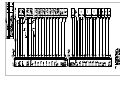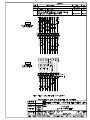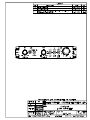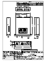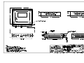
1
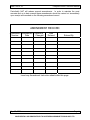
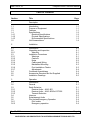
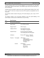
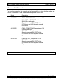
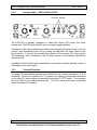
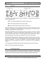
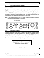
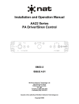
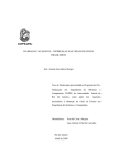
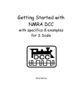
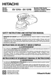
SM21
AA12
Compact Audio Controller
INSTALLATION AND OPERATION MANUAL
REV 4.10 September 9, 2004
Northern Airborne Technology Ltd.
1925 Kirschner Road
Kelowna BC, Canada.
V1Y 4N7
Telephone (250) 763-2232
Facsimile (250) 762-3374
Copyright 2004 by Northern Airborne Technology
CONFIDENTIAL AND PROPRIETARY TO NORTHERN AIRBORNE TECHNOLOGY LTD.
SM21 Rev.4.10
Compact Audio Controller Manual
Periodically NAT will release manual amendments. In order to maintain the most
accurate and up to date manual these amendments should be carried out immediately
upon receipt and recorded on the following amendment record.
AMENDMENT RECORD
Amendment Amendment
Number
Date
Section(s)
Changed
Date
Entered
Entered By
Insert any Amendment Instruction sheets after this page.
Sep 09, 2004
Page ii
ENG-FORM: 820-0109.DOT
CONFIDENTIAL AND PROPRIETARY TO NORTHERN AIRBORNE TECHNOLOGY LTD.
SM21 Rev.4.10
Compact Audio Controller Manual
Table of Contents
Section
Title
1
Description
1.1
1.2
1.3
1.4
1.4.1
1.4.2
1.4.3
1.5
Introduction
Purpose of Equipment
Features
Specifications
Electrical Specifications
Physical Specifications
Environmental Specifications
Unit Nomenclature
2
Installation
2.1
2.2
2.2.1
2.3
2.3.1
2.3.2
2.3.3
2.3.4
2.3.5
2.3.6
2.3.7
2.4
2.5
2.6
Introduction
Unpacking and Inspection
Warranty
Installation Procedures
Warnings
Cautions
Notes
Cabling and Wiring
Mechanical Mounting
Post-Installation Checks
Adjustments
Continued Airworthiness
Accessories Required But Not Supplied
Installation Drawings
3
Operation
3.1
3.2
3.3
3.3.1
3.3.2
3.3.3
3.4
3.5
3.6
3.6.1
3.6.2
Introduction
General
Radio Selection
Receive Audio – AA12-001
Receive Audio – AA12-002/AA12T-002
Transmit Selection
Intercom
Entertainment Audio
Pilot Isolate/Emergency Operation
Pilot Isolate
Emergency operation
Sep 09, 2004
Page
1-1
1-1
1-1
1-2
1-2
1-3
1-3
1-4
2-1
2-1
2-1
2-1
2-1
2-2
2-2
2-2
2-3
2-3
2-4
2-4
2-4
2-5
3-1
3-1
3-1
3-1
3-2
3-2
3-3
3-3
3-4
3-4
3-4
Page iii
ENG-FORM: 820-0109.DOT
CONFIDENTIAL AND PROPRIETARY TO NORTHERN AIRBORNE TECHNOLOGY LTD.
SM21 Rev. 4.10
AA12 Compact Audio Controller Manual
Section 1 Description
1.1
Introduction
This manual contains information on the AA12 Compact Audio Controller. All derivative
products will be covered by manual supplements, which can be obtained from NAT as
required.
Information in this section consists of purpose of equipment, features and specifications.
1.2
Purpose of Equipment
The AA12 is a compact audio controller that provides full boom microphone (MIC)
support and high performance audio for up to six crew positions with VOX, LIVE and
KEYED ICS capability. Boom MIC control is provided for pilot and copilot transmit
capability, with the pilot retaining priority. Muting of the entertainment and/or intercom
audio is accomplished during the various operational modes, providing improved
intelligibility of the audio delivered to the user.
The very small size and extensive radio and intercom functions make this an excellent
choice for many installations. The AA12 is intended for use in situations where radio
selection, audio performance and size are all critical elements.
The audio characteristics of the AA12 are derived directly from the AA80 family, and the
AA12 delivers the same reliable performance. The compact ‘radio select’ functions
provide all the necessary capability for most general aviation and light commercial
operations, with up to four transceivers and four receivers (depending on model).
1.3
Features
The AA12 system employs NAT's unique audio processing, which reduces noise and
tailors the frequency response to produce clean, crisp audio under difficult conditions. This
results in better on-board communication and greatly reduced noise fatigue for the pilot.
Two crew positions have full TX/RX/ICS capability and four are RX/ICS only. PILOT
ISO operation is provided, along with fail passive switching for the Pilot. Front panel
annunciation provides indication of TX and ICS operations. A fully illuminated front
panel is provided for low light operations.
Over voltage and reverse voltage protection circuits ensure operability in severe aircraft
environments.
Sep 9, 2004
Page 1-1
ENG-FORM: 800-0107.DOT
CONFIDENTIAL AND PROPRIETARY TO NORTHERN AIRBORNE TECHNOLOGY LTD.
AA12 Compact Audio Controller Manual
SM21 Rev. 4.10
The AA12 features NAT's ICS TIE LINE, allowing it to be connected to any other NAT
audio product with the same feature, and a MUSIC input, with the music muted by TX,
RX or ICS activity.
Internal control is provided for radio receive level, artificial transmit sidetone level, music
level, and ATC mute level. Intercom level and VOX squelch are adjustable from the
front panel.
ICS operation allows transmit during any ICS mode simply by use of any TX PTT
switch.
The different models of the unit permit variations of the front panel labeling of the
inputs/outputs, and the option of either Dzus or tray mounting.
1.4
Specifications
1.4.1
Electrical Specifications
Input Power:
14 or 28 Vdc nominal
Supply Current:
250 mA (max)
Lighting Current:
60 mA @ 28 Vdc typical
120 mA @ 14 Vdc typical
Headset Power:
60 mW typical/150 Ω Headset
Total output power 320 mW typical.
Indicators:
Bi-color LED: Green = Transmit
Orange = Intercom
Controls:
Page 1-2
Front panel:
ICS Volume
VOX Threshold
ISO/NORM Mode Select
RX Audio Select
TX Select
Internal:
ATC Muting
Sidetone (Artificial)
RX Volume
Music Level
Sep 9, 2004
ENG-FORM: 800-0107.DOT
CONFIDENTIAL AND PROPRIETARY TO NORTHERN AIRBORNE TECHNOLOGY LTD.
SM21 Rev. 4.10
1.4.2
AA12 Compact Audio Controller Manual
Inputs:
6 Standard HI Z MICs
(250 mVrms for full output)
1 Music (3 Vp-p, 600 Ω input Z)
7 Radio (2.5 Vrms, 1 kΩ input Z)
1 ICS Key (ground seeking)
1 ICS Tie Line (ICS expansion)
2 TX Keys (ground seeking)
1 Direct Audio
Outputs:
6 HI Z Headsets (150–600 Ω)
4 Transmitter MIC/Key/Lo
Physical Specifications
1.4.3
Height:
1.1” (28.5 mm)
Length:
5.8” (146.1 mm) behind panel
Width:
5.8” (146.1 mm) in front of panel
4.9” (124.5 mm) behind panel
Weight:
1.0 lb (450 g)
Mounting:
AA12 - Panel mount, Dzus fasteners (4)
AA12T - Tray Mount
Environmental Specifications
Operating Temperature:
-40 °C to +70 °C
Storage Temperature:
-55 °C to +85 °C
Altitude:
25,000’
Humidity:
95% Non-condensing
Sep 9, 2004
Page 1-3
ENG-FORM: 800-0107.DOT
CONFIDENTIAL AND PROPRIETARY TO NORTHERN AIRBORNE TECHNOLOGY LTD.
AA12 Compact Audio Controller Manual
1.5
SM21 Rev. 4.10
Unit Nomenclature
The models covered by this manual are the base units from which all other models are
derived. For details of other available models, please contact NAT.
Model
Description
AA12-001
COM1, COM2, COM3 Transceivers + PA
NAV, ADF and DME/MKR switches
28 Vdc Blue-white lights
Supports standard NAT ICS Tie Line
ICS Volume and VOX Squelch controls
Dzus mount
AA12-002
COM1, COM2, COM3 Transceivers + PA
4 unswitched inputs
28 Vdc Blue-white lights
Supports standard NAT ICS Tie Line
ICS Volume and VOX Squelch controls
Dzus mount
AA12T-002
COM, FM, AUX Transceivers + PA
28 Vdc Blue-white lights
Supports standard NAT ICS Tie Line
ICS Volume and VOX Squelch controls
Tray mount
End of section 1
Page 1-4
Sep 9, 2004
ENG-FORM: 800-0107.DOT
CONFIDENTIAL AND PROPRIETARY TO NORTHERN AIRBORNE TECHNOLOGY LTD.
SM21 Rev. 4.10
AA12 Compact Audio Controller Manual
Section 2 Installation
2.1
Introduction
Information in this section consists of: unpacking and inspection procedures, installation
procedures, post-installation checks, and installation drawings.
2.2
Unpacking and Inspection
Unpack the equipment carefully and locate the warranty card. Inspect the unit visually
for damage due to shipping and report all such claims immediately to the carrier
involved. Note that each unit should have the following:
- AA12 Compact Audio Controller
- Operator’s Manual
- Warranty Card
- Release certification
Verify that all items are present before proceeding and report any shortage immediately
to your supplier.
2.2.1
Warranty
Complete the warranty card information and send it to NAT when the installation is
complete. If you fail to complete the warranty card, the warranty is effective from the
date of shipment from NAT.
Note: An appropriately rated facility, e.g. Certified Aircraft Repair Station, must install
this equipment in accordance with applicable regulations. NAT Ltd’s warranty is not
valid unless an authorized NAT Dealer installs the equipment. Failure to follow any of
the installation instructions, or installation by a non-certified individual or agency will
void the warranty, and may result in a non-airworthy installation.
2.3
Installation Procedures
2.3.1
Warnings
Do not bundle any lines from this unit with transmitter coax lines. Do not bundle any
audio or DC power lines from this unit with 400 Hz synchro wiring or AC power lines.
Do not position this unit next to any device with a strong alternating magnetic field such
as an inverter, motor or blower, or significant audio interference will result.
Sep 9, 2004
Page 2-1
ENG-FORM: 805-0106.DOT
CONFIDENTIAL AND PROPRIETARY TO NORTHERN AIRBORNE TECHNOLOGY LTD.
AA12 Compact Audio Controller Manual
2.3.2
SM21 Rev. 4.10
Cautions
In all installations, use shielded cable exactly as shown and ground as indicated.
Significant problems could result from not following these guidelines.
Shield and route the microphone (MIC) and ICS tie lines used in the AA12 installation
appropriately. Not doing this can result in poor performance of the aircraft audio system.
The operation of the VOX intercom can be severely degraded by mixing different
manufacturer's microphones in the aircraft intercom system. NAT recommends that all
microphones be identical for optimum performance of the ICS VOX intercom
All audio installations can be seriously degraded by incorrect wiring and shielding, and
may result in abnormal cross-talk, hum and ground-loop noise. Be especially careful
with all MIC wiring and Tie Line wiring, as these lines carry the lowest level signals in
the aircraft.
All MIC and headset jacks should be electrically isolated from the airframe or significant
ground loop noise may result.
2.3.3
Notes
Audio performance can be impaired by the introduction of airframe electrical noise at
the headset jack locations. For best results, all headset jacks should be fully isolated
from the airframe.
2.3.4
Cabling and Wiring
All unshielded wire should be MIL-W-22759 or equivalent. For shielded wire
applications, use Tefzel MIL-C-27500 or Mil-M81044 single conductor and shielded wire
with solder sleeves (for shield terminations) to make the most compact and easily
terminated interconnect. Follow the wiring diagrams in Section 2.4 as required.
Allow 3 inches from the end of the wire to the shield termination to allow the hood to be
easily installed. Note that the hood is a “clamshell” hood, and is installed after the
wiring is complete.
All wiring should be at least 22 AWG except power and ground lines which should be at
least 20 AWG. Ensure that all ground connections are clean and well secured.
Page 2-2
Sep 9, 2004
ENG-FORM: 805-0106.DOT
CONFIDENTIAL AND PROPRIETARY TO NORTHERN AIRBORNE TECHNOLOGY LTD.
SM21 Rev. 4.10
2.3.5
AA12 Compact Audio Controller Manual
Mechanical Mounting
For the standard AA12 units, mounting is accomplished in a standard Dzus rack or rail
assembly with a clearance opening of 5 inches, a full width dimension of 5.75 inches,
and a total of 1.125 inches of rail height. Verify that adequate rear cable clearance is
left when planning console installations.
The AA12T variants are tray-mounted units. The required cutout dimensions are given
on drawing AA12T\IKC\922-0 at the end of this section.
2.3.6
Post-Installation Checks
If any preset requires adjustment, be sure this is carried out before the aircraft leaves,
and that the unit and its mating connector are secured before departure. Make all
required log book entries, electrical load, weight and balance amendments and other
paperwork as required by your local regulatory agency.
2.3.6.1
Voltage/resistance checks
Check the following:
Do not attach the AA12 until the following conditions are met:
P101, pin <1> for +14/28 Vdc relative to ground.
P101, pin <14> for continuity to ground (less than 0.5 Ω).
P102, pin <5> for +14/28 Vdc Lights relative to ground.
P102, pin <17> for continuity to ground (less than 0.5 Ω).
Review the installation and perform continuity checks from the AA12 to the applicable
source/destination connections that are interfaced to the unit.
2.3.6.2
Power On checks
Check the following:
Install the AA12 and power up the systems.
Turn on the Audio Controller.
Verify normal operation of all intercom and radio functions, including NORMAL and ISO
operations from the pilot position. For more information refer to Section 3.0 for specific
operation details.
Sep 9, 2004
Page 2-3
ENG-FORM: 805-0106.DOT
CONFIDENTIAL AND PROPRIETARY TO NORTHERN AIRBORNE TECHNOLOGY LTD.
AA12 Compact Audio Controller Manual
2.3.7
SM21 Rev. 4.10
Adjustments
The unit is shipped from the factory with all internal adjustments set to the normal test
levels. Once installed in the aircraft, it may be desirable to change some of these
settings to best suit the local operating environment. The internal adjustments that can
be varied are located along the left side of the unit and are as follows:
ATC Adjusts the trigger point for music muting from an incoming radio source. Fully
CCW will disable the music input. Fully CW will disable the ATC MUTE capability for
the music.
S/T Adjusts level of internally generated artificial sidetone. Should be used only if
sidetone is not produced by existing radios. Normally set to OFF (fully CCW).
RX
Adjusts level of receive audio from radio equipment. Should be balanced for
adequate level in both InterVOX and PIL ISO modes of operation, when monitored from
the pilot position.
MUSIC
mid range.
Adjusts level of external music source (Walkman, etc.). Typically set to
Upon satisfactory completion of all performance checks, make the required log
entries and complete the necessary Regulatory Agency paperwork before
releasing the aircraft for service.
2.4
Continued Airworthiness
Maintenance of the AA12 is ‘on condition’ only. Periodic maintenance of this product is
not required.
2.5
Accessories Required But Not Supplied
Installation kit p/n D25P25SL-IKC is required to complete the installation. The kit
consists of one D25SL-IKC 25-pin D-min Female Crimp Kit, and one D25PL-IKC 25-pin
D-min Male Crimp Kit. These consist of the following:
D25SL-IKC
Quantity
Description
NAT Part #
1
25
1*
1*
1
D-min 25 Socket Housing
MS Crimp Socket
Jack Screw Set
Lock Clip Set
25 Pin Connector Hood
20-21-025
20-26-901
20-27-002
20-27-004
20-29-026
Page 2-4
Sep 9, 2004
ENG-FORM: 805-0106.DOT
CONFIDENTIAL AND PROPRIETARY TO NORTHERN AIRBORNE TECHNOLOGY LTD.
SM21 Rev. 4.10
AA12 Compact Audio Controller Manual
D25PL-IKC
Quantity
Description
NAT Part #
1
25
1*
1*
1
D-min 25 Pin Housing
MS Crimp Pin
Jack Screw Set
Lock Clip Set
25 Pin Connector Hood
20-11-025
20-26-891
20-27-002
20-27-004
20-29-026
* Use as required.
2.6
Installation Drawings
DRAWING
REV.
DESCRIPTION
TYPE
AA12\001\403-0
1.10
Compact Audio Controller
Interconnect
AA12\001\405-0
1.12
Compact Audio Controller
Connector Map
AA12\001\905-0
1.12
Compact Audio Controller
Faceplate
AA12\001\922-0
1.10
Compact Audio Controller
Mechanical Installation
AA12\002\403-0
1.00
Compact Audio Controller
Interconnect
AA12\002\403-1
1.00
Compact Audio Controller
Interconnect
AA12\002\405-0
1.00
Compact Audio Controller
Connector Map
AA12\002\905-0
1.01
Compact Audio Controller
Faceplate
AA12\002\922-0
1.00
Compact Audio Controller
Mechanical Installation
Use AA12\002\403-0
1.00
Compact Audio Controller
Interconnect
Use AA12\002\405-0
1.00
Compact Audio Controller
Connector Map
Use AA12\002\905-0
1.01
Compact Audio Controller
Faceplate
Use AA12\001\922-0
1.10
Compact Audio Controller
Mechanical Installation
AA12T\IKC\922-0
1.00
AA12T Tray Assembly
Mechanical Installation
AA12-001
AA12-002
AA12T-002
Section 2 ends after these Drawings
Sep 9, 2004
Page 2-5
ENG-FORM: 805-0106.DOT
CONFIDENTIAL AND PROPRIETARY TO NORTHERN AIRBORNE TECHNOLOGY LTD.
Confidential and Proprietary to NAT
Confidential and Proprietary to NAT
SM21 Rev. 4.10
AA12 Compact Audio Controller Manual
Section 3 Operation
3.1
Introduction
Information in this section consists of the functional and operational procedures for the
AA12 Compact Audio Controller, and is applicable to the AA12-001, the AA12-002 and
the AA12T-002 unless otherwise noted.
3.2
General
The AA12 is a compact audio controller that provides full boom microphone (MIC)
support and high performance audio for up to six crew positions with VOX, LIVE and
KEYED ICS capability. Boom MIC control is provided for pilot and copilot transmit
capability, with the pilot retaining priority. Muting of the entertainment and/or intercom
audio is accomplished during the various operational modes, providing improved
intelligibility of the audio delivered to the user.
3.3
Radio Selection
3.3.1
Receive Audio – AA12-001
RX Select Switches
Annunciator
TX Select Switch
The AA12-001 is typically configured to select the receive (RX) audio from three
transceivers and up to four additional receivers. The RX select switches are centre-off
toggle switches.
Receiver audio can be selected by setting the applicable RX select switch to the down
position, and transceiver audio can be selected by setting the applicable RX select
switch to the up position, or as a function of the transmit (TX) select switch. The
transceiver that is selected by the TX select switch is automatically selected for receive
as well.
An additional Direct Audio input (unswitched) is provided for airframe warning, rad alt, or
other high priority audio signal.
Sep 9, 2004
Page 3-1
ENG-FORM: 806-0106.DOT
CONFIDENTIAL AND PROPRIETARY TO NORTHERN AIRBORNE TECHNOLOGY LTD.
AA12 Compact Audio Controller Manual
3.3.2
SM21 Rev. 4.10
Receive Audio – AA12-002/AA12T-002
RX Select Switches
The AA12-002 is typically configured to select the receive (RX) audio from three
transceivers. The RX select switches are two-position toggle switches.
Transceiver audio can be selected by setting the applicable RX select switch to the up
position, and deselected (turned off) by setting the applicable RX select switch to the
down position. It can also be selected as a function of the transmit (TX) select switch.
The transceiver that is selected by the TX select switch is automatically selected for
receive as well.
An additional Direct Audio input (unswitched) is provided for airframe warning, rad alt, or
other high priority audio signal.
3.3.3
Transmit Selection
The rotary TX select switch provides radio selection for up to three transceivers (1, 2, 3)
and a PA. The AA12 is activated for TX operation by selecting the desired transceiver
on the rotary TX select switch and pressing the external TX PTT switch. This connects
the active MIC to the selected transceiver. The front panel annunciator illuminates
green to indicate TX operation.
Page 3-2
Sep 9, 2004
ENG-FORM: 806-0106.DOT
CONFIDENTIAL AND PROPRIETARY TO NORTHERN AIRBORNE TECHNOLOGY LTD.
SM21 Rev. 4.10
3.4
AA12 Compact Audio Controller Manual
Intercom
ICS Volume Control
VOX Squelch Control
The AA12 provides three modes of intercom operation, as selected by the position of
the VOX Squelch control:
LIVE VOX Squelch positioned fully counter-clockwise (ccw)
VOX VOX Squelch positioned in the active range
MAX (keyed) VOX Squelch positioned fully clockwise (cw)
When the VOX Squelch control is adjusted to the fully ccw direction, the AA12 is in LIVE
ICS mode. The front panel annunciator illuminates orange and any sound picked up by
the MIC(s) is transferred over the ICS system.
When the VOX Squelch control is adjusted to the fully cw direction, the AA12 is in MAX
(keyed) ICS mode. The front panel annunciator remains dark and no sound is picked
up by the MIC(s) unless keyed. The MAX (keyed) ICS mode should be used in
environments where it is impractical or impossible to use LIVE or VOX modes.
When the VOX Squelch control is adjusted to any position other than fully ccw or fully
cw the AA12 is in VOX ICS mode. The annunciator can be used as a guide to properly
set the VOX Squelch. To set the VOX Squelch, from the ccw position of the VOX
Squelch control, slowly advance the control in a cw direction until the annunciator
turns off.
The front panel ICS VOLUME control controls the headset volume for all ICS modes.
Note: ICS is muted during transmit operations.
3.5
Entertainment Audio
The AA12 has a rear MUSIC input that allows signals from a Walkman or Discman type
device to be introduced into the aircraft audio system. This input is muted during
transmit functions, when the intercom is active, and during reception of radio audio.
Sep 9, 2004
Page 3-3
ENG-FORM: 806-0106.DOT
CONFIDENTIAL AND PROPRIETARY TO NORTHERN AIRBORNE TECHNOLOGY LTD.
AA12 Compact Audio Controller Manual
3.6
Pilot Isolate/Emergency Operation
3.6.1
Pilot Isolate
SM21 Rev. 4.10
The Pilot Isolate switch is a red, two-position toggle switch. This switch can be set to
NORM for normal use. However, the AA12 provides split bus operation, allowing the
pilot to be removed from the intercom and entertainment channels. By setting the
switch to PILOT ISO, the pilot is connected directly to the radios, leaving the copilot and
passengers to continue to use the intercom and hear entertainment, but not be
interrupted by the pilot or any incoming radio traffic. The green annunciator does not
illuminate for the pilot transmit operations in the PILOT ISO mode.
Note: In this mode, the copilot's MIC is not locked out and transmission is possible,
although incoming radio audio is not received.
Pilot Isolate Switch
3.6.2
Emergency operation
If the AA12 loses power for any reason, it changes to the Power Fail mode and the pilot
is connected directly to the radios for EMERGENCY operation. The external TX PTT
switch still functions in this mode. This mode is similar to the PILOT ISO mode except
that all copilot and passenger functions are lost since they depend on external power.
The front panel annunciator failing to light under any condition indicates a power failure.
CAUTION:
The pilot should confirm that all aspects of
EMERGENCY operation are working before
accepting the aircraft into service.
End of section 3
Page 3-4
Sep 9, 2004
ENG-FORM: 806-0106.DOT
CONFIDENTIAL AND PROPRIETARY TO NORTHERN AIRBORNE TECHNOLOGY LTD.